Download - Atlas Copco Tools Talk Tps Manual
User guide
TPS ControlAtlas Copco Industrial Technique AB
9836 5819 01Edition 1.2
2014-03

Copyright Atlas Copco Industrial Technique AB
Note! This manual can be altered without further notice.
For further information log in to Atlas Copco www.atlascopco.com
ContentsTPS Control1 Introduction ............................................................................................................5
1.1 Safety and operating instructions ................................................................................51.2 System overview .........................................................................................................51.3 TPS controller .............................................................................................................7
1.3.1 User Interface ................................................................................................................................8
1.3.2 Connections ...................................................................................................................................9
1.4 ToolsTalk TPS ...........................................................................................................132 Setup ......................................................................................................................15
2.1 Starting TPS ..............................................................................................................152.2 Setting up TPS ..........................................................................................................15
2.2.1 Setting up system parameters .....................................................................................................15
2.2.2 Setting up input and output parameters .......................................................................................15
2.2.3 Setting up encoder parameters ....................................................................................................16
2.2.4 Setting up start parameters ..........................................................................................................20
2.3 Connecting TPS to tool control systems ...................................................................202.3.1 Connecting to Power Focus 4000 ................................................................................................20
2.3.2 Connecting to Power Focus 600 ..................................................................................................23
2.3.3 Connecting to Tensor DS Drive D312 or DL Drive D313 .............................................................25
2.3.4 Connecting to MicroTorque G4 ....................................................................................................27
2.3.5 Connecting to MicroTorque Focus 400 ........................................................................................29
2.3.6 Connecting to EBL RE-Drive .......................................................................................................31
2.3.7 Connecting to air tools .................................................................................................................33
2.4 Installing an I/O extension board ...............................................................................343 Operation ..............................................................................................................39
3.1 Quick guide ...............................................................................................................393.2 Job handling ..............................................................................................................39
3.2.1 Creating new job ..........................................................................................................................40
3.2.2 Starting existing job ......................................................................................................................41
3.2.3 Changing existing job ...................................................................................................................42
4 Maintenance ..........................................................................................................454.1 Firmware updates .....................................................................................................45
4.1.1 Initiating firmware update from ToolsTalk TPS .............................................................................45
4.1.2 Initiating firmware update with an executable file ........................................................................47
39836 5819 01
Table of content
5 Reference ..............................................................................................................495.1 Parameters ................................................................................................................49
5.1.1 System parameter ........................................................................................................................49
5.1.2 Input configuration .......................................................................................................................51
5.1.3 Output configuration .....................................................................................................................53
5.1.4 Sequence .....................................................................................................................................54
5.1.5 Position ........................................................................................................................................56
5.1.6 Air option parameter ....................................................................................................................57
5.1.7 Barcode input ...............................................................................................................................57
5.1.8 Service .........................................................................................................................................59
5.2 I/O configuration ........................................................................................................605.2.1 Communication between TPS and Power Focus ........................................................................60
5.2.2 Communication between TPS and Tensor DS/DL Drive .............................................................60
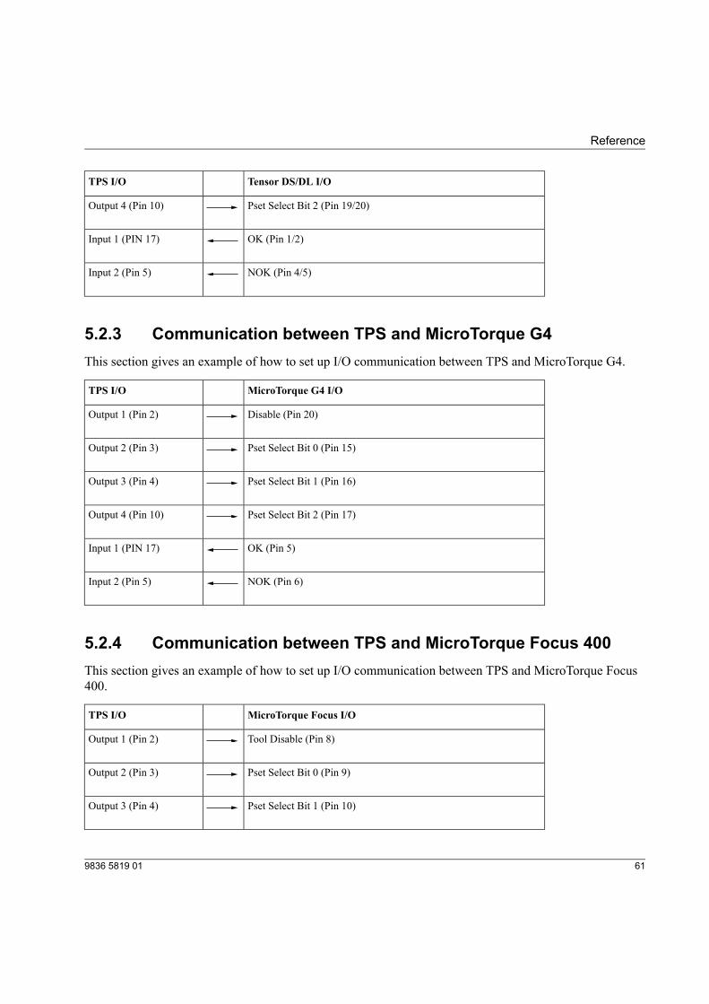
5.2.3 Communication between TPS and MicroTorque G4 ....................................................................61
5.2.4 Communication between TPS and MicroTorque Focus 400 ........................................................61
5.2.5 Communication between TPS and EBL RE-Drive .......................................................................62
5.3 Licence handling .......................................................................................................625.4 Pneumatic function ....................................................................................................63
5.4.1 Licensed function .........................................................................................................................63
5.4.2 Pneumatic monitoring and controlling ..........................................................................................63
5.4.3 Setting up TPS in a pneumatic system ........................................................................................65
5.4.4 Programming pressure sensors ...................................................................................................66
5.4.5 Troubleshooting ...........................................................................................................................67
5.5 Barcode function .......................................................................................................685.5.1 Licensed function .........................................................................................................................68
5.5.2 Description ...................................................................................................................................68
5.5.3 Barcode definition parameters .....................................................................................................69
5.6 Reporting function .....................................................................................................715.6.1 Licensed function .........................................................................................................................71
5.6.2 Description ...................................................................................................................................71
5.6.3 Procedure ....................................................................................................................................72
5.7 Printout ......................................................................................................................72
9836 5819 014
Table of content

1 Introduction
1.1 Safety and operating instructionsTWARNING Read all warnings and all instructions.The safety and operating instructions as described in the Atlas Copco Product instructions that is includedin the delivery of the systemmust be read and complied. Ensure that you read and understand all instructions.Failure to follow all the instructions may result in electric shock, fire and/or serious personal injury. Alllocally legislated safety regulations with regard to installation, operation and maintenance must be adheredto at all times. Refer installation and servicing to qualified personnel only.
Save all instructions for future reference.
Contact your Atlas Copco representative if questions regarding the safety and operating instructions arise.
1.2 System overviewThis user guide describes how to install, configure and use the Tool Positioning System (TPS) Control.
TPS Control is used for controlling and monitoring the tightening sequences and positioning operations fora variety of pneumatic and electronic tools. The TPS Control system is designed for the modern assemblyindustry with high demands on quality and production efficiency, and offers full modularity through thecombination of different hardware and software.
59836 5819 01
Introduction
F1
ESC MENU
INFO
START NOK RESET
VAL
OK
F2 F3
J04: JOB.MOTOR P1
Cycle: 1
1
RESET
2 3 4
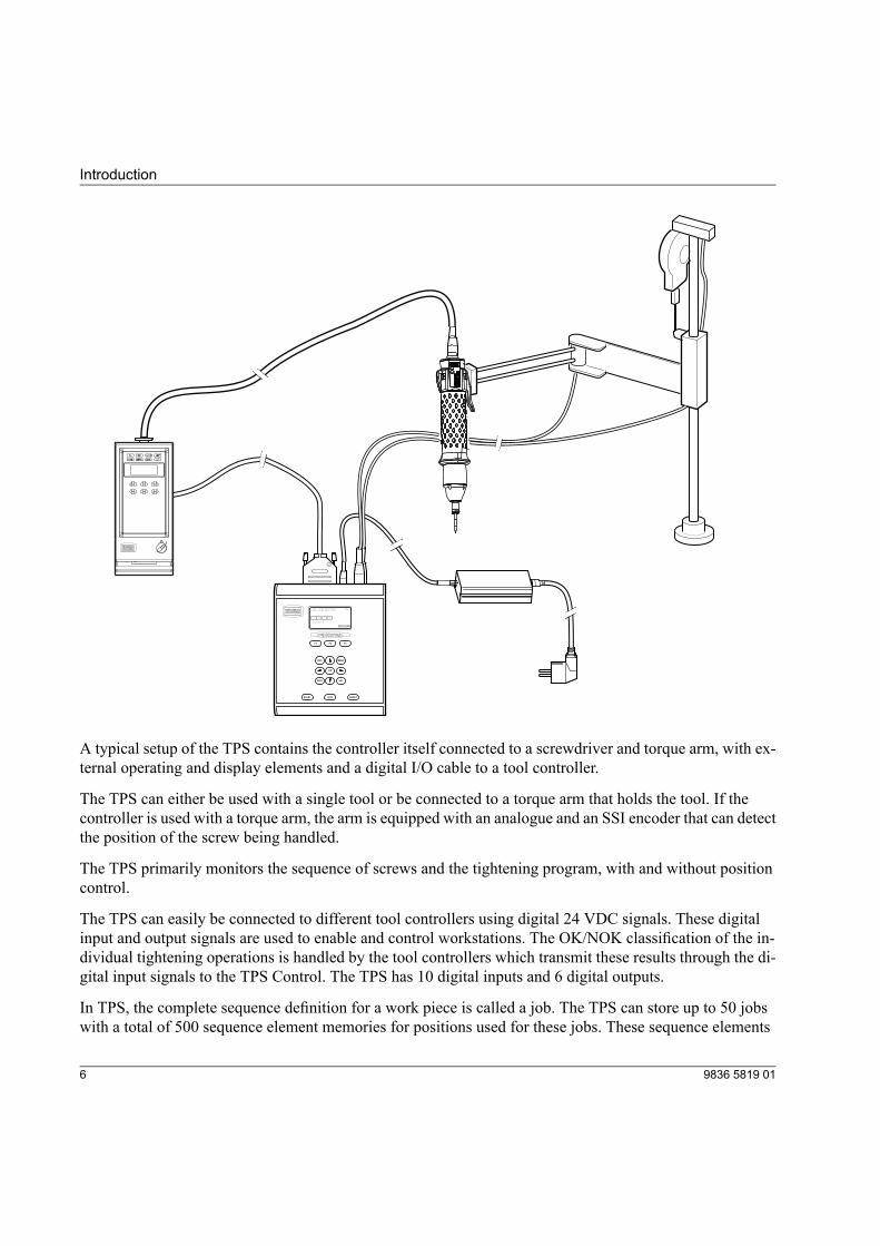
A typical setup of the TPS contains the controller itself connected to a screwdriver and torque arm, with ex-ternal operating and display elements and a digital I/O cable to a tool controller.
The TPS can either be used with a single tool or be connected to a torque arm that holds the tool. If thecontroller is used with a torque arm, the arm is equipped with an analogue and an SSI encoder that can detectthe position of the screw being handled.
The TPS primarily monitors the sequence of screws and the tightening program, with and without positioncontrol.
The TPS can easily be connected to different tool controllers using digital 24 VDC signals. These digitalinput and output signals are used to enable and control workstations. The OK/NOK classification of the in-dividual tightening operations is handled by the tool controllers which transmit these results through the di-gital input signals to the TPS Control. The TPS has 10 digital inputs and 6 digital outputs.
In TPS, the complete sequence definition for a work piece is called a job. The TPS can store up to 50 jobswith a total of 500 sequence element memories for positions used for these jobs. These sequence elements
9836 5819 016
Introduction
can be freely allocated to the 50 supported jobs. Each position within a job can be assigned to a specific Pset,or several positions can be assigned to the same Pset. Psets are configured in the ToolsTalk software, whichcontains the complete set of parameters that control the tightening process.
TPS Control can also handle additional functions, such as input queries defined for specific positions andexternal starting signals and output signals used in clamping procedures.
TPS Control can either be powered with an external power supply unit or through an external power signalfrom the tool controller. The external power supply unit and cord are ordered separately. Note that an externalpower supply unit is required for air tools, MicroTorque and EBL RE-Drive.
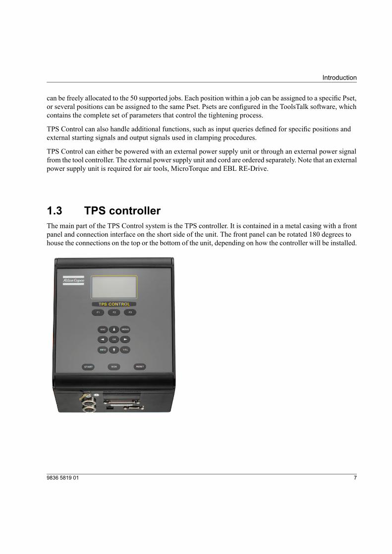
1.3 TPS controllerThe main part of the TPS Control system is the TPS controller. It is contained in a metal casing with a frontpanel and connection interface on the short side of the unit. The front panel can be rotated 180 degrees tohouse the connections on the top or the bottom of the unit, depending on how the controller will be installed.
79836 5819 01
Introduction
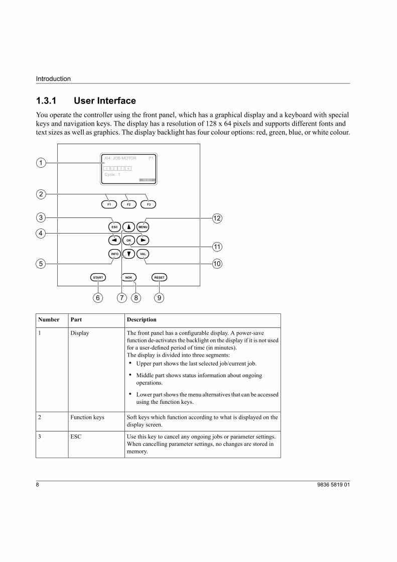
1.3.1 User InterfaceYou operate the controller using the front panel, which has a graphical display and a keyboard with specialkeys and navigation keys. The display has a resolution of 128 x 64 pixels and supports different fonts andtext sizes as well as graphics. The display backlight has four colour options: red, green, blue, or white colour.
F1
ESC MENU
INFO
START NOK RESET
VAL
OK
F2 F3
J04: JOB.MOTOR P1
Cycle: 1
1
RESET
2 3 4
1
2
3
4
5
9
10
11
12
86 7
DescriptionPartNumber
The front panel has a configurable display. A power-savefunction de-activates the backlight on the display if it is not usedfor a user-defined period of time (in minutes).
Display1
The display is divided into three segments:• Upper part shows the last selected job/current job.
• Middle part shows status information about ongoingoperations.
• Lower part shows themenu alternatives that can be accessedusing the function keys.
Soft keys which function according to what is displayed on thedisplay screen.
Function keys2
Use this key to cancel any ongoing jobs or parameter settings.When cancelling parameter settings, no changes are stored inmemory.
ESC3
9836 5819 018
Introduction
DescriptionPartNumber
Use these keys to display parameter options or to create/removepositions when programming new jobs.
Left/Right arrow key4
Press this key to get information about the TPS Control deviceID, firmware version and activated licensed functions.
INFO5
Use this key to start selected job.START6
When in parameter list, use these keys to go up or down in thelist to select a desired parameter.
Up/DownArrow keys7
For selected parameter, use the up/down arrow keys to changethe options of the parameter.
Use this key to release the tool after a position has resulted inNOK state and the tool is disabled. This is only used if parameterNOK acknowledge has been set to ON.
NOK8
Use this key to stop the ongoing job during any time of theprocedure
RESET9
Use this key to validate and store all changed parameters inmemory
VAL10
Use this key to open the list with possible options for a selectedparameter or confirm the selected option for the parameter.
OK11
Use this key to enter the setup menu parametersMENU12
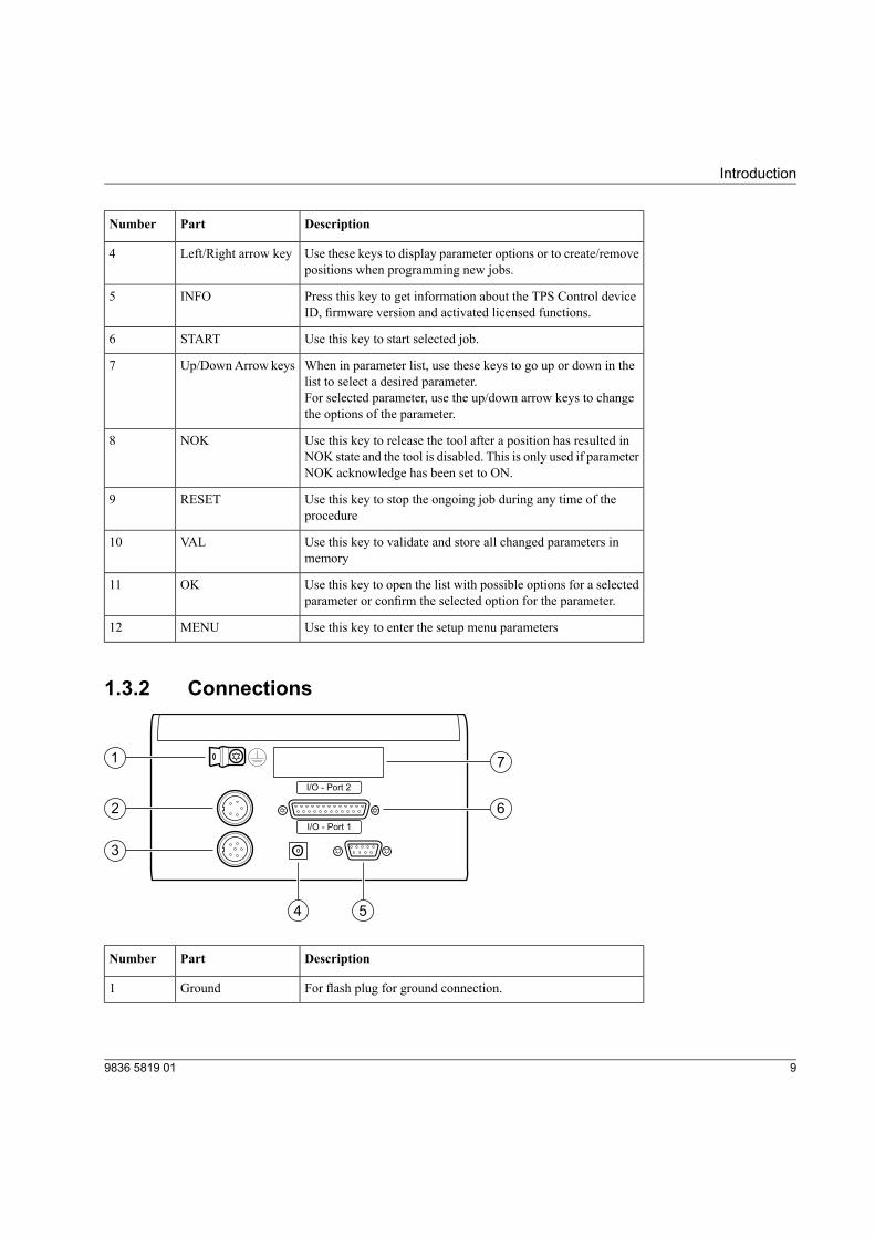
1.3.2 Connections
I/O - Port 2
I/O - Port 1
1
2
3
4 5
6
7
DescriptionPartNumber
For flash plug for ground connection.Ground1
99836 5819 01
Introduction
DescriptionPartNumber
For 5-pin flange socket (Binder, Series 680) connected to theanalogue encoder on the torque arm
Analogue encoderinterface
2
For 7-pin flange socket (binder, Series 680) connected to theangle encoder on the torque arm
SSI encoder interface3
For connection to the 24 VDC power supply unit, 5.5 mm socketwith 2.1 mm center pin
Power supply4
For 9-pin Sub-D socket connected to the external equipment, forexample Barcode scanner or PC
RS-232C serialinterface
5
For 25-pin Sub-D socket connected to the tool controller.Digital I/O connectionI/O Port 1
6
Not used.I/O Port 27
1.3.2.1 Ground connectionA 6.3 mm flash plug used for ground connection. This connection must be linked to the protective groundfor safe operation of the TPS Control.
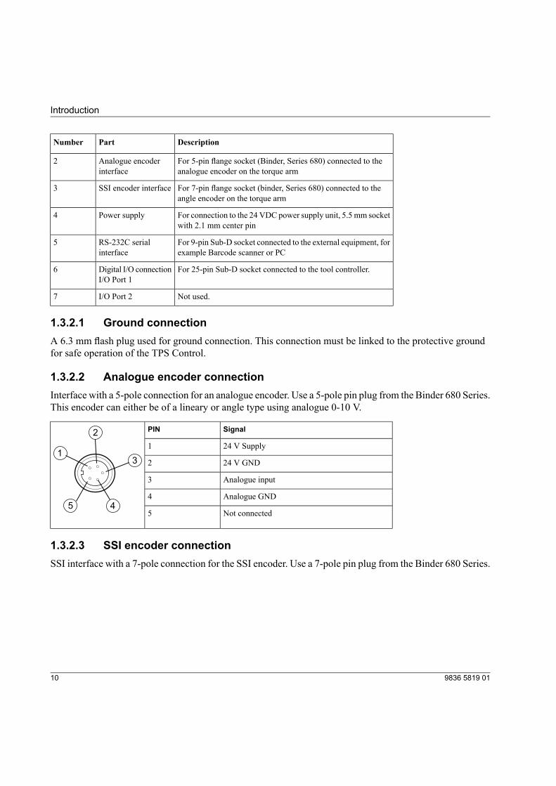
1.3.2.2 Analogue encoder connectionInterface with a 5-pole connection for an analogue encoder. Use a 5-pole pin plug from the Binder 680 Series.This encoder can either be of a lineary or angle type using analogue 0-10 V.
SignalPIN
1
2
3
45
24 V Supply1
24 V GND2
Analogue input3
Analogue GND4
Not connected5
1.3.2.3 SSI encoder connectionSSI interface with a 7-pole connection for the SSI encoder. Use a 7-pole pin plug from the Binder 680 Series.
9836 5819 0110
Introduction
SignalPIN
1
2
3
4
56
7
24 V Supply1
Clock +2
Clock -3
Data -4
Data +5
Not connected6
24 V GND7
1.3.2.4 Power supplyThe TPS Control is powered by an external 24-volt power supply unit. The external power supply unit canbe ordered as an accessory from Atlas Copco.
As an alternative, the unit can be supplied with 24 VDC from an external power signal through the I/O plug.
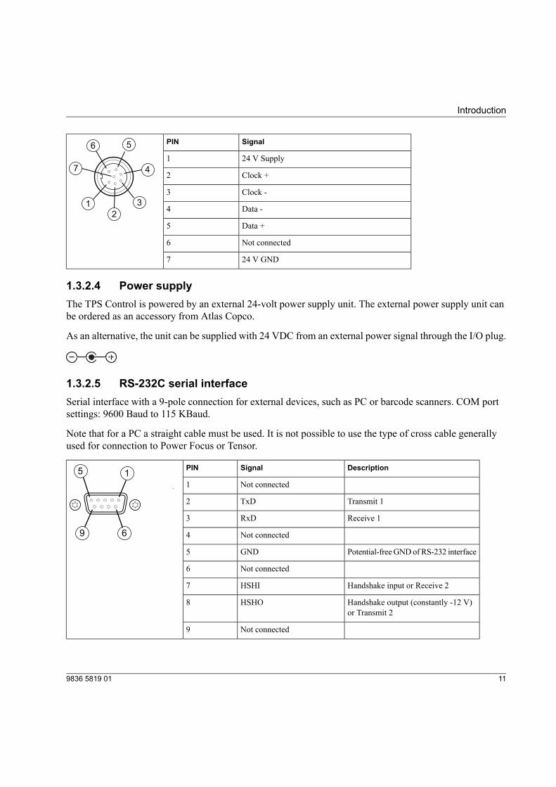
1.3.2.5 RS-232C serial interfaceSerial interface with a 9-pole connection for external devices, such as PC or barcode scanners. COM portsettings: 9600 Baud to 115 KBaud.
Note that for a PC a straight cable must be used. It is not possible to use the type of cross cable generallyused for connection to Power Focus or Tensor.
DescriptionSignalPIN15
69
Not connected1
Transmit 1TxD2
Receive 1RxD3
Not connected4
Potential-freeGNDof RS-232 interfaceGND5
Not connected6
Handshake input or Receive 2HSHI7
Handshake output (constantly -12 V)or Transmit 2
HSHO8
Not connected9
119836 5819 01
Introduction
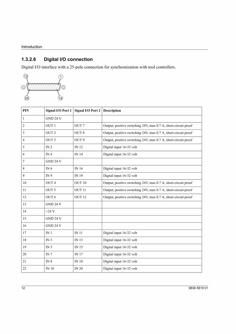
1.3.2.6 Digital I/O connectionDigital I/O interface with a 25-pole connection for synchronization with tool controllers.
113
1425
DescriptionSignal I/O Port 2Signal I/O Port 1PIN
GND 24 V1
Output, positive switching 24V, max 0.7 A, short-circuit proofOUT 7OUT 12
Output, positive switching 24V, max 0.7 A, short-circuit proofOUT 8OUT 23
Output, positive switching 24V, max 0.7 A, short-circuit proofOUT 9OUT 34
Digital input 16-32 voltIN 12IN 25
Digital input 16-32 voltIN 14IN 46
GND 24 V7
Digital input 16-32 voltIN 16IN 68
Digital input 16-32 voltIN 19IN 99
Output, positive switching 24V, max 0.7 A, short-circuit proofOUT 10OUT 410
Output, positive switching 24V, max 0.7 A, short-circuit proofOUT 11OUT 511
Output, positive switching 24V, max 0.7 A, short-circuit proofOUT 12OUT 612
GND 24 V13
+24 V14
GND 24 V15
GND 24 V16
Digital input 16-32 voltIN 11IN 117
Digital input 16-32 voltIN 13IN 318
Digital input 16-32 voltIN 15IN 519
Digital input 16-32 voltIN 17IN 720
Digital input 16-32 voltIN 18IN 821
Digital input 16-32 voltIN 20IN 1022
9836 5819 0112
Introduction
DescriptionSignal I/O Port 2Signal I/O Port 1PIN
GND 24 V23
GND 24 V24
Not connected25
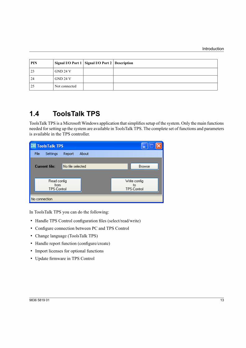
1.4 ToolsTalk TPSToolsTalk TPS is aMicrosoftWindows application that simplifies setup of the system. Only themain functionsneeded for setting up the system are available in ToolsTalk TPS. The complete set of functions and parametersis available in the TPS controller.
In ToolsTalk TPS you can do the following:
• Handle TPS Control configuration files (select/read/write)
• Configure connection between PC and TPS Control
• Change language (ToolsTalk TPS)
• Handle report function (configure/create)
• Import licenses for optional functions
• Update firmware in TPS Control
139836 5819 01
Introduction

2 Setup
2.1 Starting TPS1. Connect cables and ground connection according to section 1.3, TPS Controller.
2. Switch on the power. The controller starts up immediately.
2.2 Setting up TPS
2.2.1 Setting up system parametersThis section describes how to set up general system parameters in TPS.
1. Press MENU.2. Press SETUP.3. The default language is English. If you want to change the language, go to Service and press OK to enter
the menu.
4. Select the appropriate language in User language. Confirm your selection with OK. Possible languagesare English, German or French.
5. Press VAL to change to the selected language.6. Go to System parameter and press OK to enter the menu.
7. Set Special functions to ON to view advanced programming functions. Press OK.
8. Enter values for additional parameters. The parameters and options are described in detail in sectionSystem Parameters.
9. Press VAL to confirm changes or ESC to quit without making any changes.
2.2.2 Setting up input and output parametersThis section describes how to set up the input signals and output signals in TPS for communication with thetool controller. Note that the input signals in the tool controller correspond to the output signals for TPS
159836 5819 01
Setup
control, and the relays in the tool controller correspond to the input signals in TPS Control. For a completeparameter list, see section Parameters, Input Configuration and Output Configuration.
1. Go to Input configuration.2. Set the required inputs corresponding to the relays set in ToolsTalk. See section Connect TPS to tool
control systems, for an example configuration.
3. Press VAL to confirm changes or ESC to quit without making any changes.
4. Go to Output Configuration.5. Set the required outputs corresponding to the input signals set in ToolsTalk. See section Connect TPS to
tool control systems, for an example configuration.
6. Press VAL to confirm changes or ESC to quit without making any changes.
2.2.3 Setting up encoder parametersThis section describes how to set the position parameters related to the analogue and SSI encoders on thetorque arm that must be calibrated before any tightening operations can be created. For a complete list ofposition parameters, see section 5.1.5, Position.
The parameters to set are as follows:
• SSI Interface parameters
• SSI coding
• SSI factor
• SSI resolution
• Length
• Length 1 (L1)
• Length 2 (L2)
The calculations of L1 and L2 differ, depending on what type of torque arm will be used.
The following arm types can be used together with TPS:
• Angle/Linear
• Linear/Linear
• Angle/Angle A (for arm types with an horizontal arm mounted to the left, 180 degrees analogue encodermounted on the top of the arm)
• Angle/Angle B (for arm types with 360 degrees analogue encoder)
9836 5819 0116
Setup
• Angle/Angle C (for arm types with an horizontal armmounted to the right, 180 degrees analogue encodermounted on the bottom of the arm)
Note! The Rotation stop kit must be kept intact on the torque arm to ensure that the analogue and SSI encoderwill work properly. For more information on different arm types, see the applicable PI.
2.2.3.1 Setting up SSI InterfaceSee section Position to set up the parameters for SSI interface.
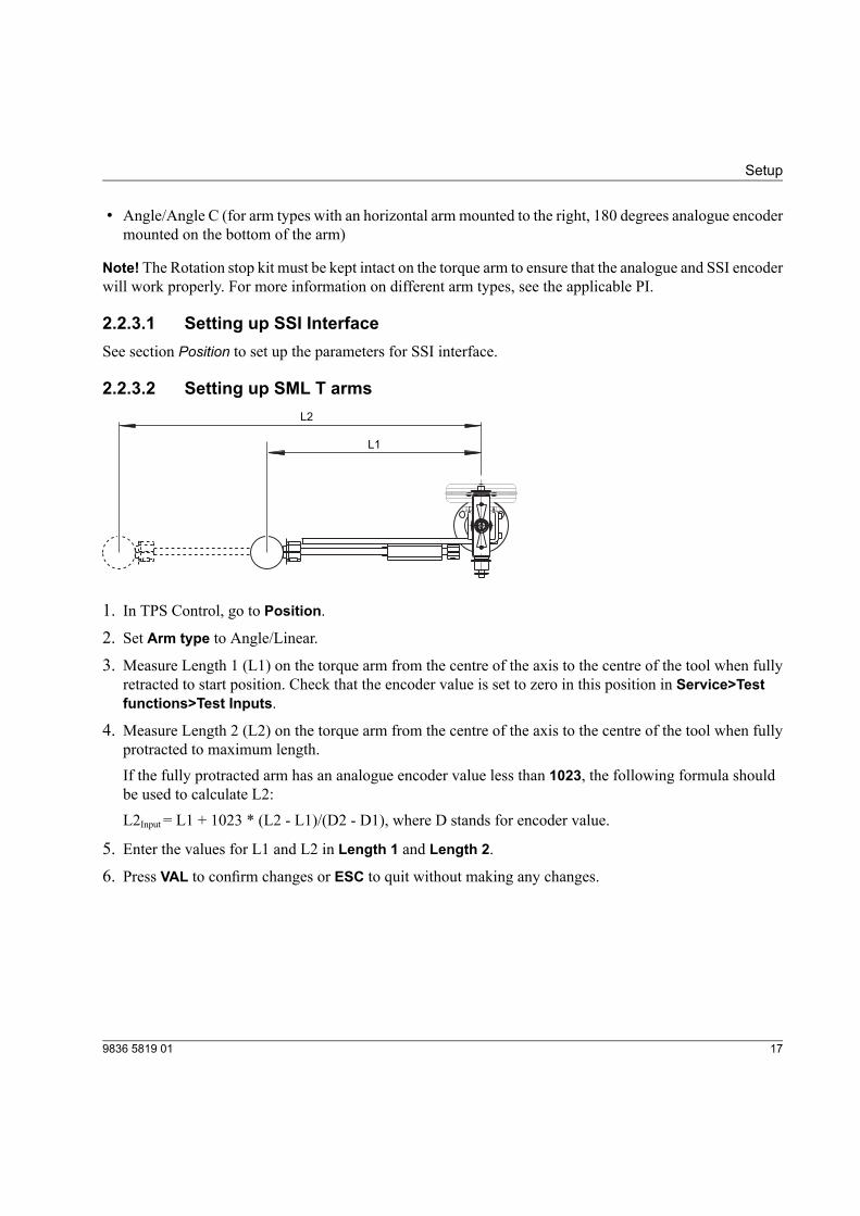
2.2.3.2 Setting up SML T armsL2
L1
1. In TPS Control, go to Position.2. Set Arm type to Angle/Linear.
3. Measure Length 1 (L1) on the torque arm from the centre of the axis to the centre of the tool when fullyretracted to start position. Check that the encoder value is set to zero in this position in Service>Testfunctions>Test Inputs.
4. Measure Length 2 (L2) on the torque arm from the centre of the axis to the centre of the tool when fullyprotracted to maximum length.If the fully protracted arm has an analogue encoder value less than 1023, the following formula shouldbe used to calculate L2:L2Input= L1 + 1023 * (L2 - L1)/(D2 - D1), where D stands for encoder value.
5. Enter the values for L1 and L2 in Length 1 and Length 2.
6. Press VAL to confirm changes or ESC to quit without making any changes.
179836 5819 01
Setup

2.2.3.3 Setting up SMS T arms
L2
L1
The figure above shows an SMS T arm from above with horizontal arm mounted to the left (angle/angle A).
1. In TPS Control, go to Position.2. Set Arm type to one of the following angle/angle values:
• Angle/Angle A (SMST, position from above: horizontal armmounted to the left, 180-degree analogueencoder mounted on top of the torque arm)
• Angle/Angle B (Positioning arm with 360-degree analogue encoder)
• Angle/Angle C (SMST, position from above: horizontal armmounted to the right, 180-degree analogueencoder mounted on bottom of the torque arm)
For more information on how to mount the positioning encoder on either the top or the bottom of thetorque arm, see the applicable torque arm instructions.
3. Measure Length 1 (L1) from the centre of the axis to the centre of the elbow when fully retracted to startposition.
4. Measure Length 2 (L2) from the centre of the elbow to the centre of the tool when fully protracted tomaximum length.
5. Enter the values for L1 and L2 in Length 1 and Length 2.
6. Press VAL to confirm changes or ESC to quit without making any changes.
9836 5819 0118
Setup
7. Go to Service>Test functions>Test inputs to check that the fully retracted arm has an analogue encodervalue of 100.For information on how to set the encoder value to 100, see the applicable torque arm instructions.
2.2.3.4 Setting up SMC POSI L arms1. In TPS Control, go to Position.2. Set Arm type to Linear/Linear.
3. Set Length 1 (L1) to 300.
4. Set Length 2 (L2) to 2000.
5. Set SSI coding to binary.6. Set SSI resolution to 24, SSI factor to 1 and SSI divider to 2.7. Press VAL to confirm changes or ESC to quit without making any changes.
See section Position for more information on how to set up the parameters for SSI interface.
2.2.3.5 Setting up SMC POSI LA arms1. In TPS Control, go to Position.2. Set Arm type to Angle/Linear 2.
3. Set Length 1 (L1) to 1056.
4. Set Length 2 (L2) to 4332,7.
5. Set SSI coding to binary.6. Set SSI resolution to 25, SSI factor to 1 and SSI divider to 4.7. Set a value for SSI code by length 0 by following the instruction below.
8. Press VAL to confirm changes or ESC to quit without making any changes.
How to retrieve the correct value for SSI code by length 0:
1. Go to TPS menu setup->service->Test functions->Test inputs.
2. By changing the arm linear position, the code for SSI sensor changes accordingly.
3. Change the arm linear position to the minimum arm length, to retrieve the correct code value to use inSSI code by length 0.
See section Position for more information on how to set up the parameters for SSI interface.
199836 5819 01
Setup
2.2.4 Setting up start parametersThis section describes how to set parameters required to start jobs with the TPS controller.
To set up start parameters controlled by external devices, see section Sequence.
1. Go to System Parameter.
2. In Job Selection, select Keyboard.
3. Go to Sequence.4. Set start signal as follows:
• Set to Edge if you want to start the job each time by pressing Start on the TPS controller.
• Set to Level to start the job the first time by pressing Start on TPS controller. After that the job isstarted automatically.
2.3 Connecting TPS to tool control systems
2.3.1 Connecting to Power Focus 4000This section describes how to configure Power Focus 4000 and TPS Control to set up communication betweenthe controllers. Power Focus has four relay contacts (outputs) and four inputs that can be used for commu-nication with TPS. All inputs and outputs can be configured using the ToolsTalk software. For a completeinstruction of PF ToolsTalk, see the applicable Power Focus user guide.
Note! This section describes an example of how to configure the tool controller and TPS. Depending on thetype of operation you may need to set the inputs and outputs to other values.
1. Check that the digital I/O cable is connected to the TPS and the Power Focus.
2. Check that a PC with the ToolsTalk PF software installed is connected to the Power Focus.
In ToolsTalk PF
1. Depending on how Power Focus is connected to the PC, make sure it is visible in eitherPFMap>EthernetConnected or PF Map>Serial.
9836 5819 0120
Setup
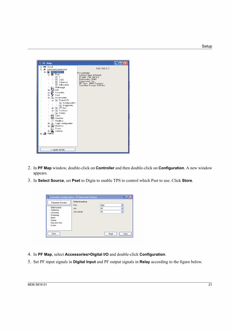
2. In PF Mapwindow, double-click on Controller and then double-click on Configuration. A new windowappears.
3. In Select Source, set Pset to Digin to enable TPS to control which Pset to use. Click Store.
4. In PF Map, select Accessories>Digital I/O and double-click Configuration.
5. Set PF input signals in Digital Input and PF output signals in Relay according to the figure below.
219836 5819 01
Setup
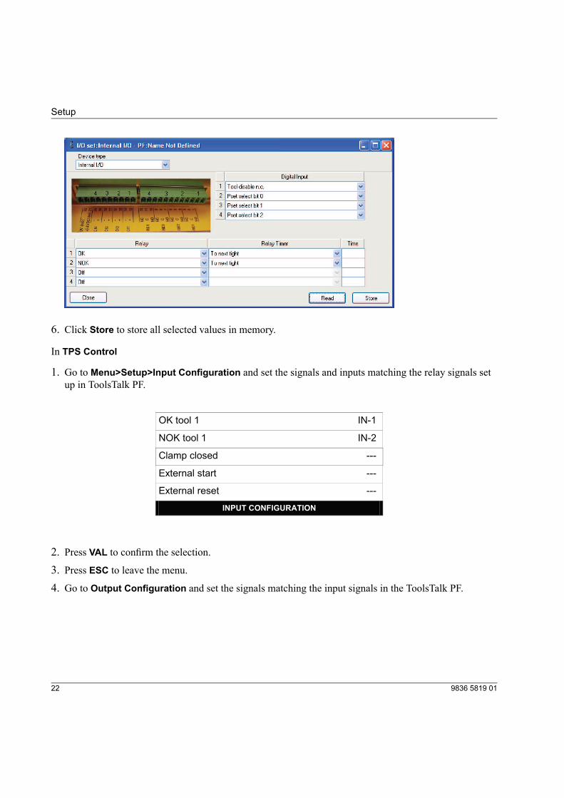
6. Click Store to store all selected values in memory.
In TPS Control
1. Go to Menu>Setup>Input Configuration and set the signals and inputs matching the relay signals setup in ToolsTalk PF.
-1
-2
Cl
OK tool 1 IN
NOK tool 1 IN
amp closed ---
External start ---
---
INPUT CONFIGURATION
External reset
2. Press VAL to confirm the selection.
3. Press ESC to leave the menu.
4. Go to Output Configuration and set the signals matching the input signals in the ToolsTalk PF.
9836 5819 0122
Setup
able OU -1
-2
-3
-4
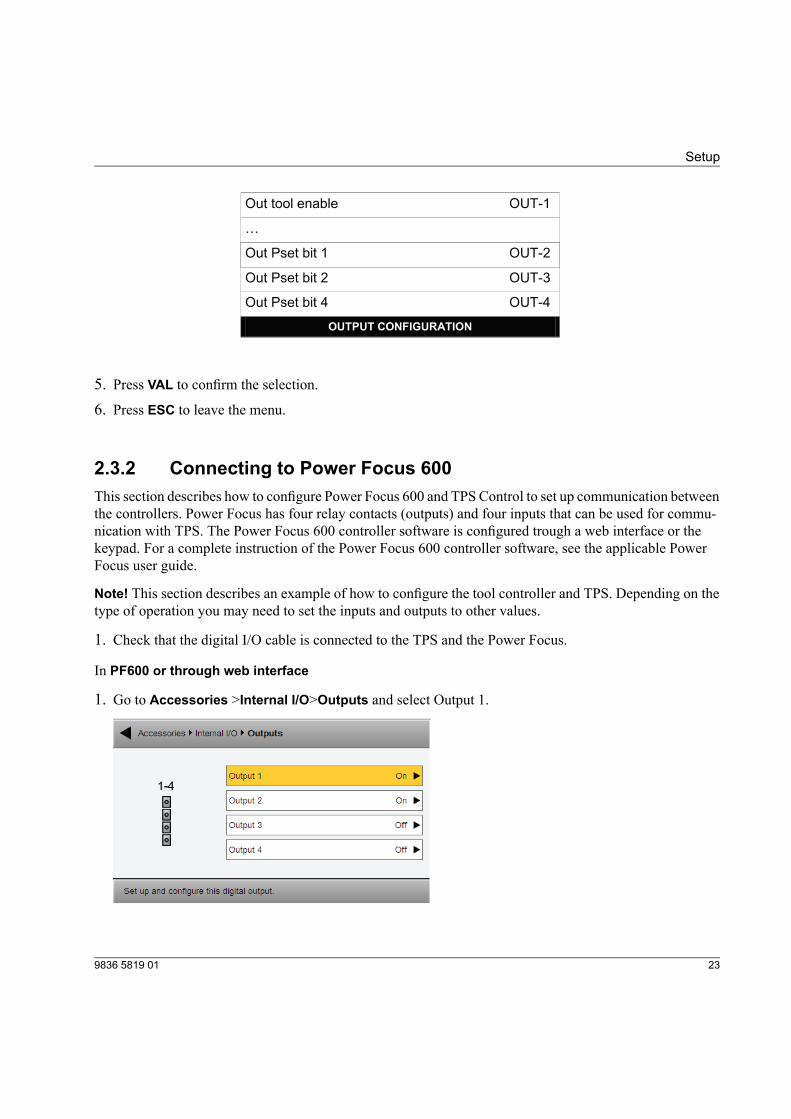
Out tool en T
…
Out Pset bit 1 OUT
Out Pset bit 2 OUT
Out Pset bit 4 OUT
OUTPUT CONFIGURATION
5. Press VAL to confirm the selection.
6. Press ESC to leave the menu.
2.3.2 Connecting to Power Focus 600This section describes how to configure Power Focus 600 and TPS Control to set up communication betweenthe controllers. Power Focus has four relay contacts (outputs) and four inputs that can be used for commu-nication with TPS. The Power Focus 600 controller software is configured trough a web interface or thekeypad. For a complete instruction of the Power Focus 600 controller software, see the applicable PowerFocus user guide.
Note! This section describes an example of how to configure the tool controller and TPS. Depending on thetype of operation you may need to set the inputs and outputs to other values.
1. Check that the digital I/O cable is connected to the TPS and the Power Focus.
In PF600 or through web interface
1. Go to Accessories >Internal I/O>Outputs and select Output 1.
239836 5819 01
Setup
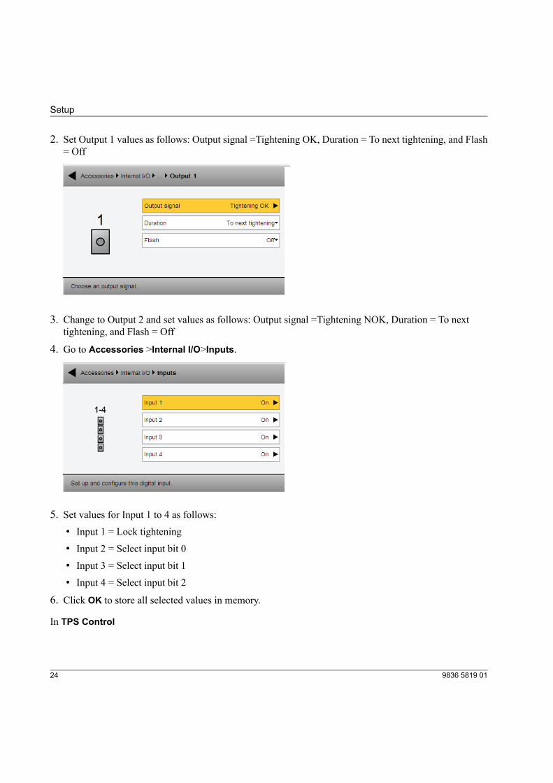
2. Set Output 1 values as follows: Output signal =Tightening OK, Duration = To next tightening, and Flash= Off
3. Change to Output 2 and set values as follows: Output signal =Tightening NOK, Duration = To nexttightening, and Flash = Off
4. Go to Accessories >Internal I/O>Inputs.
5. Set values for Input 1 to 4 as follows:• Input 1 = Lock tightening
• Input 2 = Select input bit 0
• Input 3 = Select input bit 1
• Input 4 = Select input bit 2
6. Click OK to store all selected values in memory.
In TPS Control
9836 5819 0124
Setup
1. Go to Menu>Setup>Input Configuration and set the signals and inputs matching the output signals setup in PF.
-1
-2
Cl
OK tool 1 IN
NOK tool 1 IN
amp closed ---
External start ---
---
INPUT CONFIGURATION
External reset
2. Press VAL to confirm the selection.
3. Press ESC to leave the menu.
4. Go to Output Configuration and set the signals matching the input signals set up in PF.
-1
-2
-3
-4
Out tool disable OUT
…
Out Pset bit 1 OUT
Out Pset bit 2 OUT
Out Pset bit 4 OUT
OUTPUT CONFIGURATION
5. Press VAL to confirm the selection.
6. Press ESC to leave the menu.
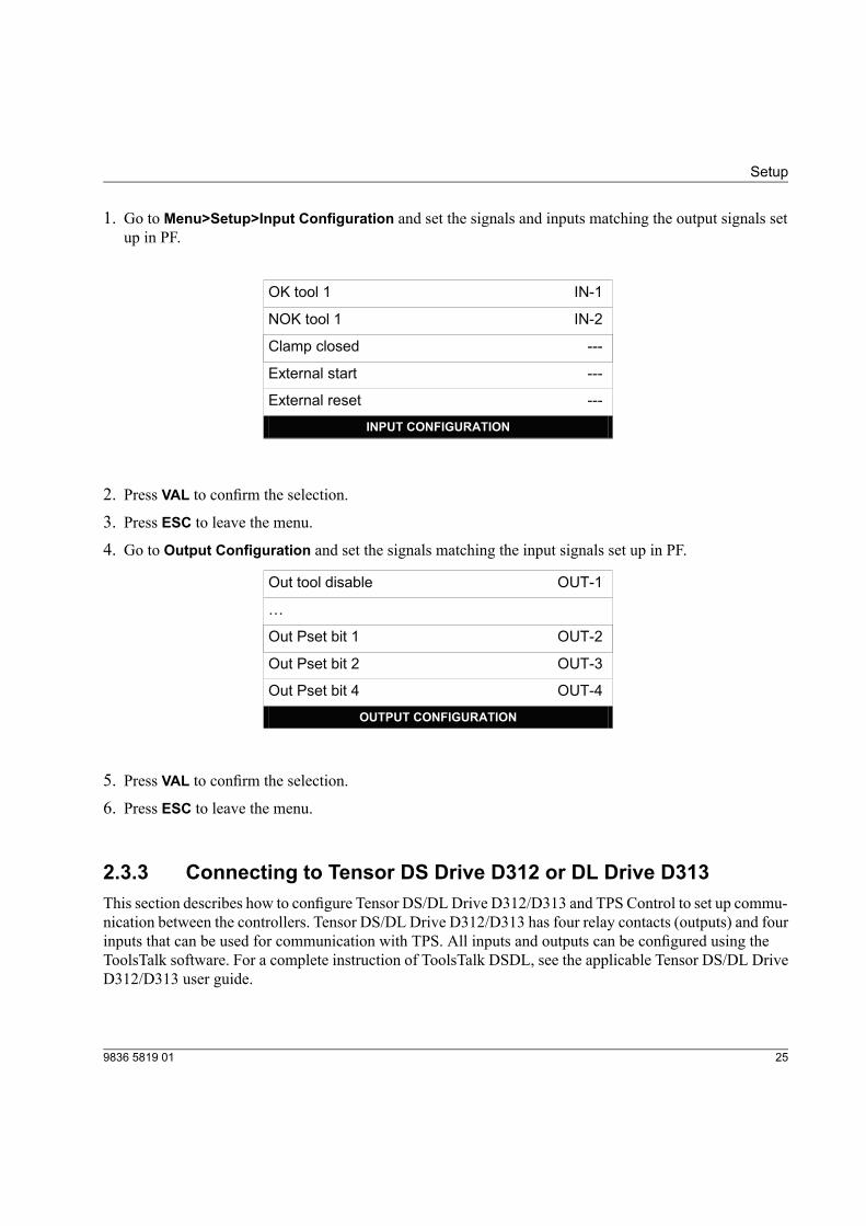
2.3.3 Connecting to Tensor DS Drive D312 or DL Drive D313This section describes how to configure Tensor DS/DLDrive D312/D313 and TPS Control to set up commu-nication between the controllers. Tensor DS/DL Drive D312/D313 has four relay contacts (outputs) and fourinputs that can be used for communication with TPS. All inputs and outputs can be configured using theToolsTalk software. For a complete instruction of ToolsTalk DSDL, see the applicable Tensor DS/DL DriveD312/D313 user guide.
259836 5819 01
Setup
Note! This section describes an example of how to configure the tool controller and TPS. Depending on thetype of operation you may need to set the inputs and outputs to other values.
1. Check that the digital I/O cable is connected to the TPS and Tensor.
2. Check that a PC with the ToolsTalk software installed is connected to Tensor.
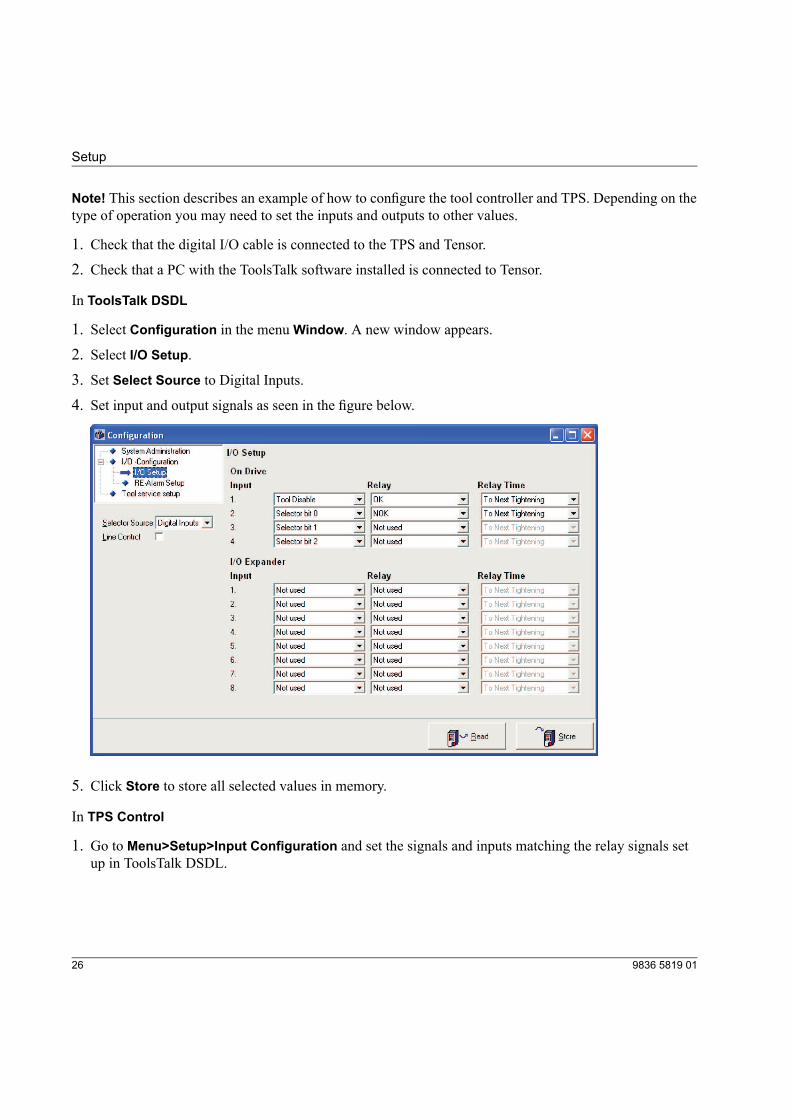
In ToolsTalk DSDL
1. Select Configuration in the menuWindow. A new window appears.
2. Select I/O Setup.
3. Set Select Source to Digital Inputs.4. Set input and output signals as seen in the figure below.
5. Click Store to store all selected values in memory.
In TPS Control
1. Go to Menu>Setup>Input Configuration and set the signals and inputs matching the relay signals setup in ToolsTalk DSDL.
9836 5819 0126
Setup
-1
-2
Cl
OK tool 1 IN
NOK tool 1 IN
amp closed ---
External start ---
---
INPUT CONFIGURATION
External reset
2. Press VAL to confirm the selection.
3. Press ESC to leave the menu.
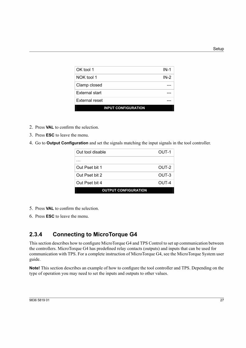
4. Go to Output Configuration and set the signals matching the input signals in the tool controller.
-1
-2
-3
-4
Out tool disable OUT
…
Out Pset bit 1 OUT
Out Pset bit 2 OUT
Out Pset bit 4 OUT
OUTPUT CONFIGURATION
5. Press VAL to confirm the selection.
6. Press ESC to leave the menu.
2.3.4 Connecting to MicroTorque G4This section describes how to configureMicroTorque G4 and TPS Control to set up communication betweenthe controllers. MicroTorque G4 has predefined relay contacts (outputs) and inputs that can be used forcommunication with TPS. For a complete instruction of MicroTorque G4, see the MicroTorque System userguide.
Note! This section describes an example of how to configure the tool controller and TPS. Depending on thetype of operation you may need to set the inputs and outputs to other values.
279836 5819 01
Setup
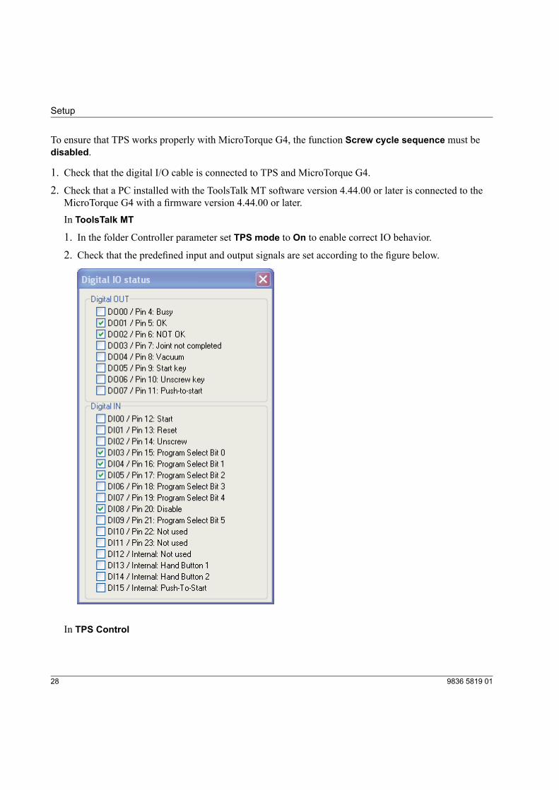
To ensure that TPS works properly with MicroTorque G4, the function Screw cycle sequence must bedisabled.
1. Check that the digital I/O cable is connected to TPS and MicroTorque G4.
2. Check that a PC installed with the ToolsTalk MT software version 4.44.00 or later is connected to theMicroTorque G4 with a firmware version 4.44.00 or later.In ToolsTalk MT
1. In the folder Controller parameter set TPS mode to On to enable correct IO behavior.
2. Check that the predefined input and output signals are set according to the figure below.
In TPS Control
9836 5819 0128
Setup
1. Go to Menu>Setup>Input Configuration and set the signals and inputs matching the relay signalsset up in ToolsTalk MT.
-1
-2
Cl
OK tool 1 IN
NOK tool 1 IN
amp closed ---
External start ---
---
INPUT CONFIGURATION
External reset
2. Press VAL to confirm the selection.
3. Press ESC to leave the menu.
4. Go to Output Configuration and set the signals matching the input signals in the tool controller.
OU -1
-2
-3
-4
Out tool disable T
…
Out Pset bit 1 OUT
Out Pset bit 2 OUT
Out Pset bit 4 OUT
OUTPUT CONFIGURATION
5. Press VAL to confirm the selection.
6. Press ESC to leave the menu.
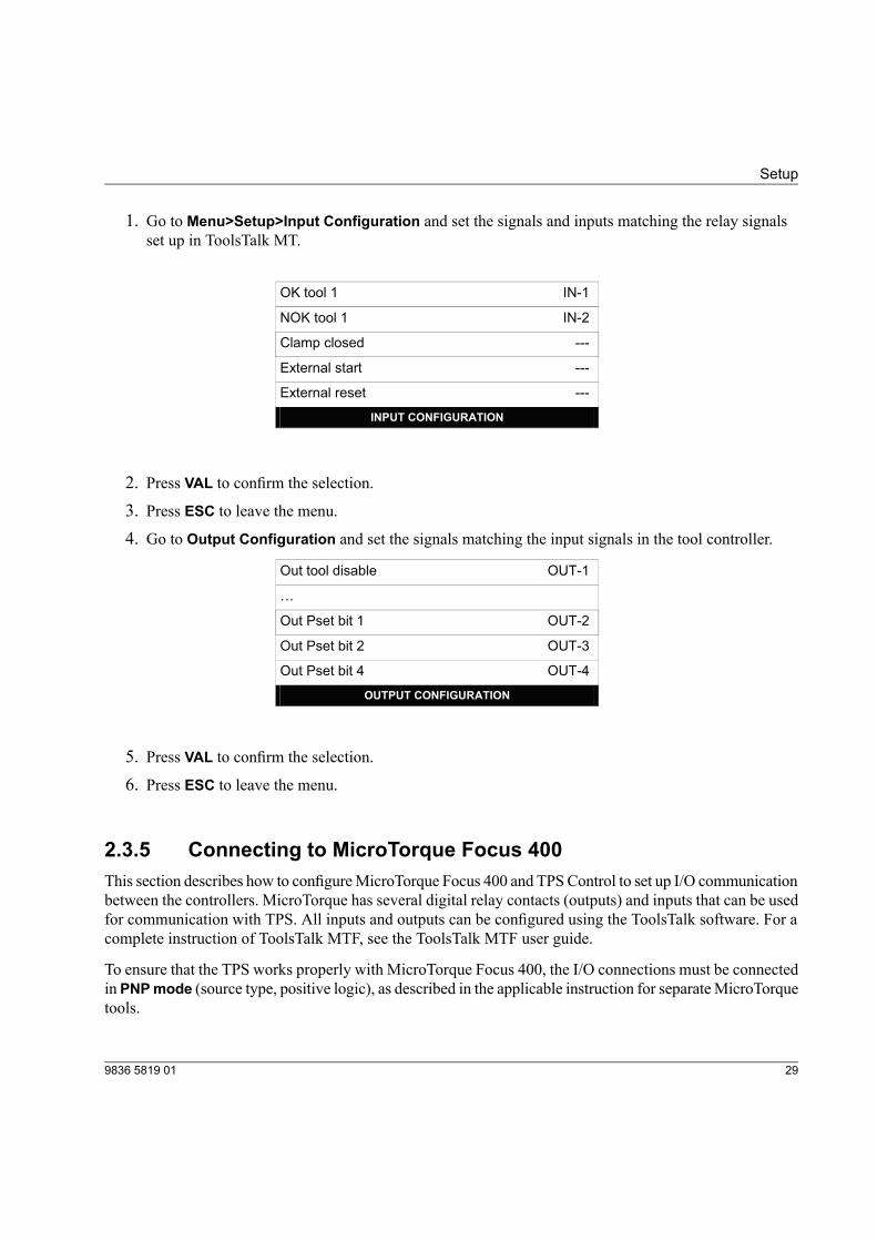
2.3.5 Connecting to MicroTorque Focus 400This section describes how to configureMicroTorque Focus 400 and TPSControl to set up I/O communicationbetween the controllers. MicroTorque has several digital relay contacts (outputs) and inputs that can be usedfor communication with TPS. All inputs and outputs can be configured using the ToolsTalk software. For acomplete instruction of ToolsTalk MTF, see the ToolsTalk MTF user guide.
To ensure that the TPS works properly with MicroTorque Focus 400, the I/O connections must be connectedin PNPmode (source type, positive logic), as described in the applicable instruction for separateMicroTorquetools.
299836 5819 01
Setup
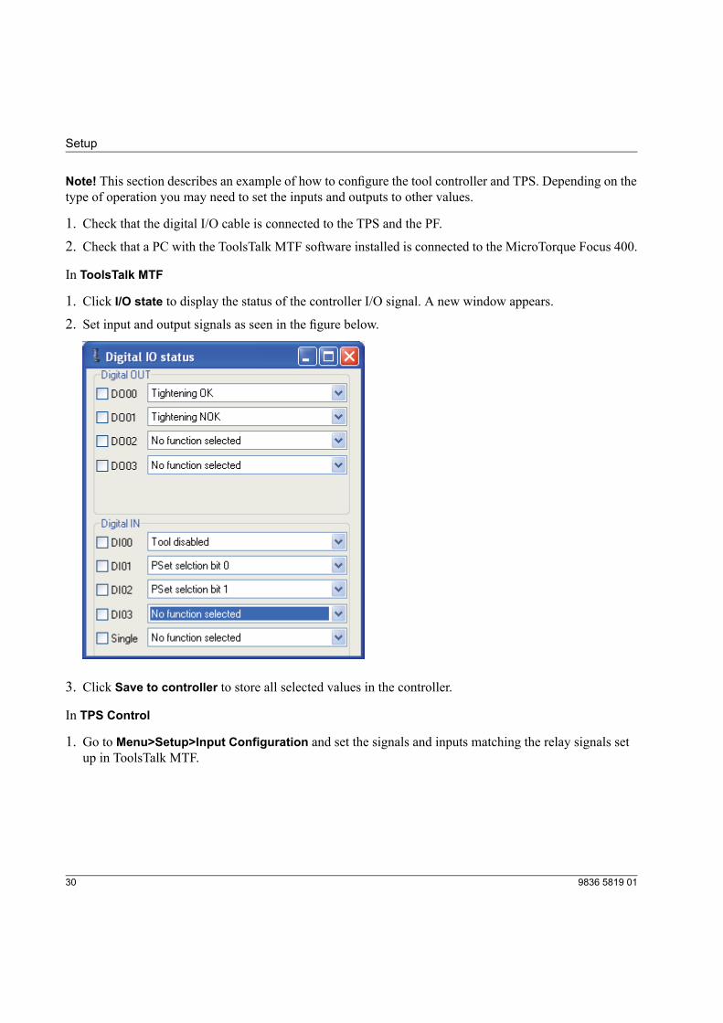
Note! This section describes an example of how to configure the tool controller and TPS. Depending on thetype of operation you may need to set the inputs and outputs to other values.
1. Check that the digital I/O cable is connected to the TPS and the PF.
2. Check that a PC with the ToolsTalk MTF software installed is connected to the MicroTorque Focus 400.
In ToolsTalk MTF
1. Click I/O state to display the status of the controller I/O signal. A new window appears.
2. Set input and output signals as seen in the figure below.
3. Click Save to controller to store all selected values in the controller.
In TPS Control
1. Go to Menu>Setup>Input Configuration and set the signals and inputs matching the relay signals setup in ToolsTalk MTF.
9836 5819 0130
Setup
-1
-2
Cl
OK tool 1 IN
NOK tool 1 IN
amp closed ---
External start ---
---
INPUT CONFIGURATION
External reset
2. Press VAL to confirm the selection.
3. Press ESC to leave the menu.
4. Go to Output Configuration and set the signals matching the input signals in the tool controller.
OU -1
-2
-3
Out tool disable T
…
Out Pset bit 1 OUT
Out Pset bit 2 OUT
Out Pset bit 4 ---
OUTPUT CONFIGURATION
5. Press VAL to confirm the selection.
6. Press ESC to leave the menu.
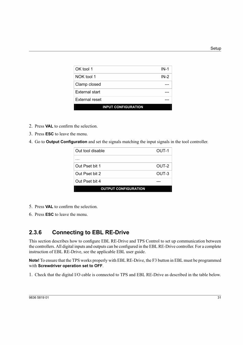
2.3.6 Connecting to EBL RE-DriveThis section describes how to configure EBL RE-Drive and TPS Control to set up communication betweenthe controllers. All digital inputs and outputs can be configured in the EBLRE-Drive controller. For a completeinstruction of EBL RE-Drive, see the applicable EBL user guide.
Note!To ensure that the TPSworks properly with EBLRE-Drive, the F3 button in EBLmust be programmedwith Screwdriver operation set to OFF.
1. Check that the digital I/O cable is connected to TPS and EBL RE-Drive as described in the table below.
319836 5819 01
Setup
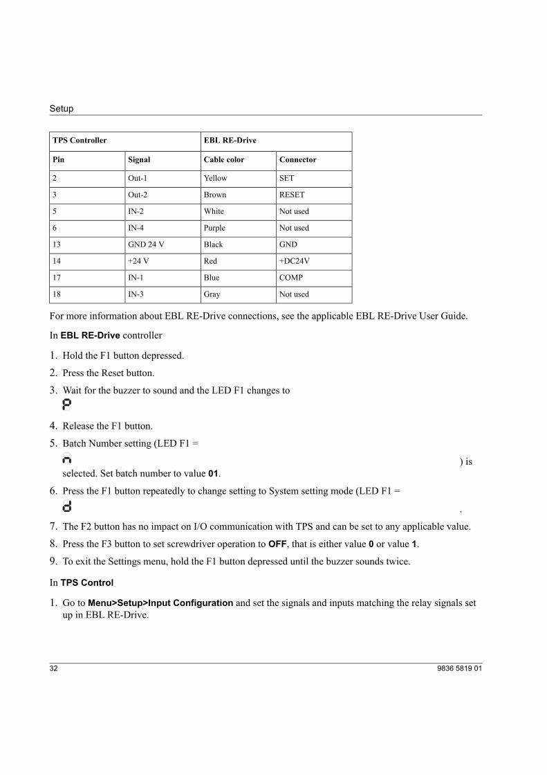
EBL RE-DriveTPS Controller
ConnectorCable colorSignalPin
SETYellowOut-12
RESETBrownOut-23
Not usedWhiteIN-25
Not usedPurpleIN-46
GNDBlackGND 24 V13
+DC24VRed+24 V14
COMPBlueIN-117
Not usedGrayIN-318
For more information about EBL RE-Drive connections, see the applicable EBL RE-Drive User Guide.
In EBL RE-Drive controller
1. Hold the F1 button depressed.2. Press the Reset button.3. Wait for the buzzer to sound and the LED F1 changes to
4. Release the F1 button.5. Batch Number setting (LED F1 =
) isselected. Set batch number to value 01.
6. Press the F1 button repeatedly to change setting to System setting mode (LED F1 =
.
7. The F2 button has no impact on I/O communication with TPS and can be set to any applicable value.
8. Press the F3 button to set screwdriver operation to OFF, that is either value 0 or value 1.9. To exit the Settings menu, hold the F1 button depressed until the buzzer sounds twice.
In TPS Control
1. Go to Menu>Setup>Input Configuration and set the signals and inputs matching the relay signals setup in EBL RE-Drive.
9836 5819 0132
Setup
-1
---
Cl
OK tool 1 IN
NOK tool 1
amp closed ---
External start ---
---
INPUT CONFIGURATION
External reset
2. Press VAL to confirm the selection.
3. Press ESC to leave the menu.
4. Go to Output Configuration and set the signals matching the input signals in the tool controller.
OU -1
Out tool enable T
Out tool disable
Out Pset bit 1 ---
Out Pset bit 2 ---
Out Pset bit 4 ---
OUTPUT CONFIGURATION
OUT-2
5. Press VAL to confirm the selection.
6. Press ESC to leave the menu.
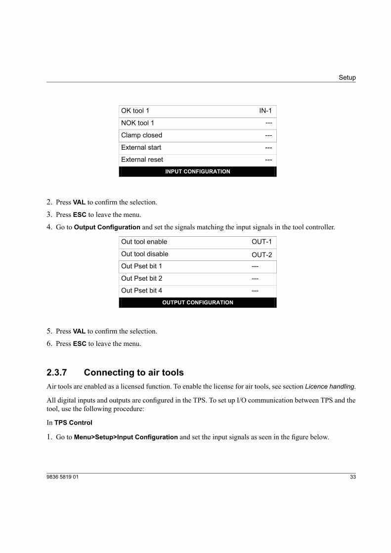
2.3.7 Connecting to air toolsAir tools are enabled as a licensed function. To enable the license for air tools, see section Licence handling.
All digital inputs and outputs are configured in the TPS. To set up I/O communication between TPS and thetool, use the following procedure:
In TPS Control
1. Go to Menu>Setup>Input Configuration and set the input signals as seen in the figure below.
339836 5819 01
Setup
IN-2
Signal clutch 1
Clamp closed
---
---
INPUT CONFIGURATION
External start
---
External reset
Signal trigger 1 IN-1
2. Press VAL to confirm the selection.
3. Press ESC to leave the menu.
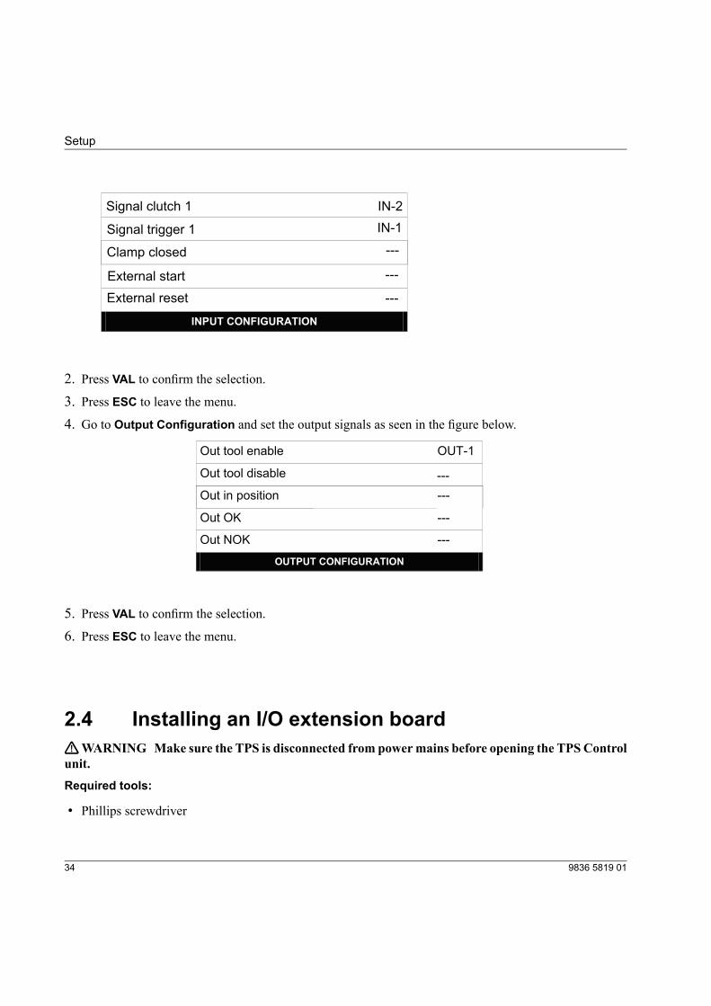
4. Go to Output Configuration and set the output signals as seen in the figure below.
able OU -1
Out tool en T
Out tool disable
Out in position ---
Out OK ---
Out NOK ---
OUTPUT CONFIGURATION
---
5. Press VAL to confirm the selection.
6. Press ESC to leave the menu.
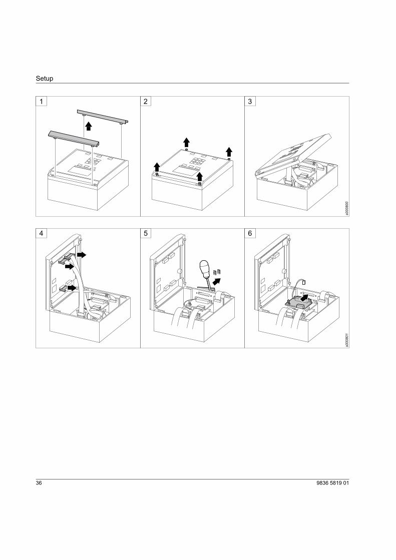
2.4 Installing an I/O extension boardTWARNING Make sure the TPS is disconnected from powermains before opening the TPSControlunit.Required tools:
• Phillips screwdriver
9836 5819 0134
Setup

• Slotted screwdriver
• Allen key
Installation procedure:
1. Remove the protective strips carefully from the front panel.
2. Using a Phillips screwdriver, unscrew the screws on the front panel.
3. Lift the front panel carefully to open the controller casing.4. Disconnect the cables from the connectors on the main board situated inside the front panel.
5. Remove the plastic cover from I/O port 2 with a slotted screwdriver. Make sure that no parts of the plasticcover, including the metal clips holding the plastic cover, are left inside the controller casing.
6. Connect the additional I/O board into the empty slot for I/O port 2.
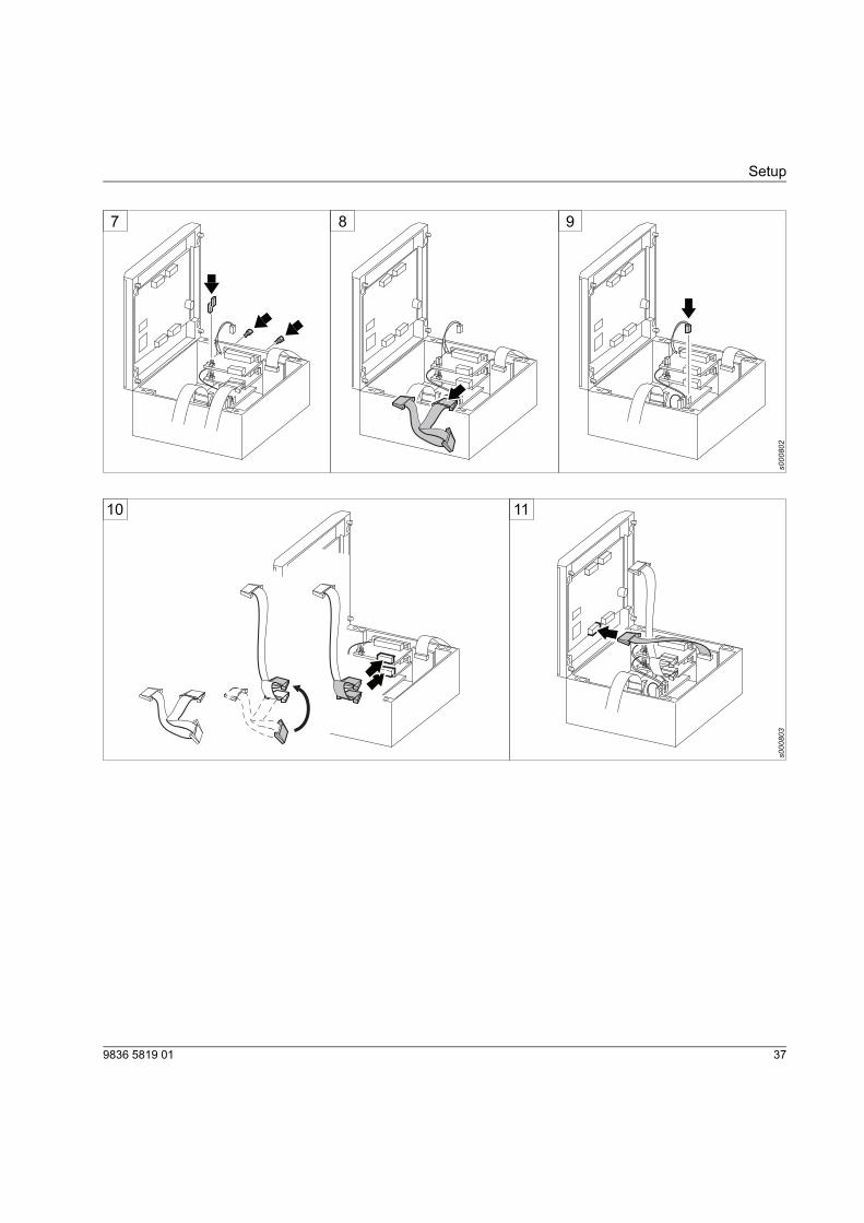
7. Fasten the board with the bolts, using an Allen key from the outside.When using the additional I/O board as an I/O extension board, make sure the board is equipped withjumpers (in closed position).
8. Disconnect the flat band cable from the original I/O board for easier connection of the additional I/Oboard.
9. Connect the paired cable from the additional I/O board into the available slots on the connector on thelower board.
10. Connect the flat band cable between the two I/O boards.
11. Connect the flat band cable from the side-mounted encoder board to the connector on top of the mainboard.
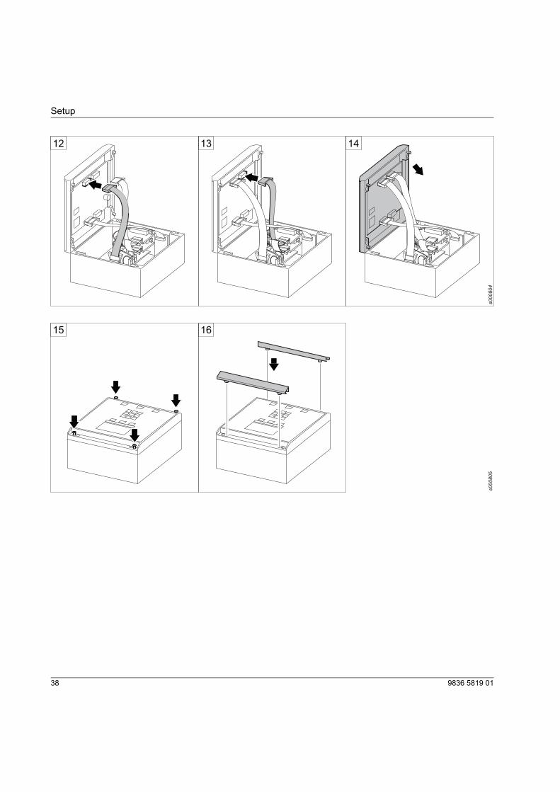
12. Connect the flat band cable from the lower board to the rightmost connector on the main board.
13. Connect the flat band cable from the I/O boards to the leftmost connector on the main board.
14. Put the front panel back in the controller casing.15. Tighten the front panel with the screws.16. Put the protective strips back on the front panel.
359836 5819 01
Setup
1 2 3
s000800
s000801
4 5 6
9836 5819 0136
Setup
s000802
7 8 9
s000803
10 11
379836 5819 01
Setup
s000804
12 13 14
s000805
15 16
9836 5819 0138
Setup
3 Operation
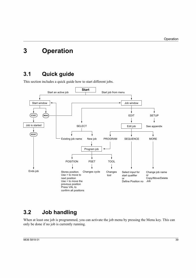
3.1 Quick guideThis section includes a quick guide how to start different jobs.
Stores position. Use > to move to
next position Use < to move the previous position Press VAL to
confirm all positions
Start
Start window
Job is started
Ends job
Start an active job
Job window
Edit job
Program job
See appendix
New job PROGRAM SEQUENCE MOREExisting job name
Start job from menu
SELECT
EDIT SETUPMENUSTART
RESET
POSITION PSET TOOL
Changes cycle Changes
tool
Select input for
start qualifieror Define Position no
Change job nameorCopy/Move/Delete Job
3.2 Job handlingWhen at least one job is programmed, you can activate the job menu by pressing the Menu key. This canonly be done if no job is currently running.
399836 5819 01
Operation
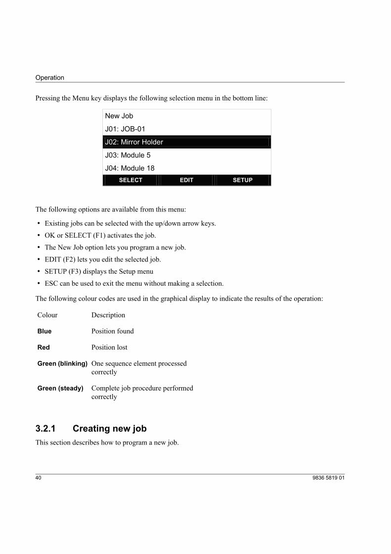
Pressing the Menu key displays the following selection menu in the bottom line:
-01
New Job
J01: JOB
J02: Mirror Holder
J03: Module 5
J04: Module 18
SELECT EDIT SETUP
The following options are available from this menu:
• Existing jobs can be selected with the up/down arrow keys.
• OK or SELECT (F1) activates the job.
• The New Job option lets you program a new job.
• EDIT (F2) lets you edit the selected job.
• SETUP (F3) displays the Setup menu
• ESC can be used to exit the menu without making a selection.
The following colour codes are used in the graphical display to indicate the results of the operation:
DescriptionColour
Position foundBlue
Position lostRed
One sequence element processedcorrectly
Green (blinking)
Complete job procedure performedcorrectly
Green (steady)
3.2.1 Creating new jobThis section describes how to program a new job.
9836 5819 0140
Operation
1. Select New Job to program a new job. The position programming window will appear. Position 1 isautomatically enabled.
2. Position the tool on the work piece where you want to program position 1. Press POSITION (F1) to storethe position in memory. The inverted box indicates that the position is stored.
3. By default, Pset 1 is always suggested for the first position.If Output Pset Selection setup parameters have already been set, you can change the Pset with the Psetkeys.Use Pset to enter the Pset number that should be transmitted to the screwdriver controller for this position.
4. Press the Right Arrow key to program the next position. The value for Pset is always copied from theprevious position but can be changed when necessary.
5. Repeat steps 2-4 for all positions you want to program. When finished, press VAL to confirm the pro-grammed positions.
If you want to delete a position during the programming procedure, press the Left Arrow key. The box withthe position will be removed.
3.2.2 Starting existing jobThis section describes how to start an already selected job or select and start an existing job from the jobmenu.
The display shows the previously selected job or, if a job is activated by an external device, the job currentlyselected through the relevant inputs.
1. To select this job, press START (F1). The job can also be started after an external start signal if the con-troller is connected to any external devices. See section 5.1, Parameters, for more details.If you want to change the job, press MENU and select any of the available jobs with the up/down arrowkeys. Press OK or SELECTto activate the job.
2. Position the tool in position 1. The LED backlight will remain white or flash green and white until theposition is reached, depending on the results of the previous tightening operation position. As soon as theposition is reached, the LED backlight will change to blue and the output enabling the screwdriver willbe activated.
3. Perform the operation for this position.
4. If the screwdriver transmits an OK signal, the position is marked as processed (the corresponding boxturns black) and the LED backlight will change to flashing green and white.Note! For EBL RE-Drive, you need to retract the tool from the current position before moving to the nextposition.
419836 5819 01
Operation
5. Move the tool to the next position. As soon as the next position is reached, the backlight will revert toblue.
6. Repeat steps 4-7 until all positions have been processed.7. When the tightening operation is completed, the box symbol indicates this by changing colour.
If you have set the parameter Enable Backstep to ON, a Back button will show as soon as at least one positionhas been completed. The Back button is used to enable a repetition of a tightening operation, even in theevent of an OK result.
If you want to stop the tightening operation, press the RESET button. Press Yes at the question Really cancelthe job?. The procedure will stop and the LED backlight will change to red. The procedure will be displayedas NOK and the operation can be restarted by pressing the START button.
If the screwdriver transmits an NOK signal, the backlight will change to red and the tool will be disabled.The next step in the procedure depends on how the unit is configured in regards to the parameters AcknowledgeNOK and NOK Max Count.
NOK acknowledgement not required: If NOK does not require an acknowledgement, the operator can imme-diately repeat the tightening operation for this screw; however, the tool must first have left the position ofthe current screw before the same screw is released again for processing. If the NOK Max Count parameteris set to any value except 0 (zero), the operator can only start the number of repeated attempts set in theparameter value. If the number is exceeded, a signal is issued and the Pset must be reset.
NOK acknowledgement required: The operator must press the NOK key on the device or, if accordinglyconfigured, activate the external Acknowledge NOK input signal (for example, with a key switch). The pos-ition will be released for repeated processing after this acknowledgement has been signalled. If NOK acknow-ledge is activated, the NOK Max Counter parameter will not be evaluated.
In both cases, the operations can be cancelled with the Reset button.
3.2.3 Changing existing jobThe EDIT menu lets you process an already-existing job. The following functions can be executed with ajob in this area:
9836 5819 0142
Operation
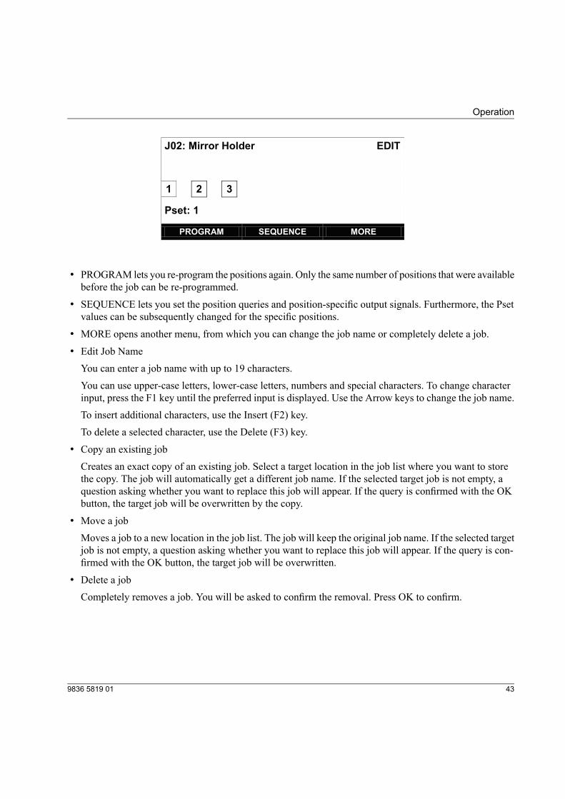
J02: Mirror Holder EDIT
1 2 3
Pset: 1
PROGRAM SEQUENCE MORE
• PROGRAM lets you re-program the positions again. Only the same number of positions that were availablebefore the job can be re-programmed.
• SEQUENCE lets you set the position queries and position-specific output signals. Furthermore, the Psetvalues can be subsequently changed for the specific positions.
• MORE opens another menu, from which you can change the job name or completely delete a job.
• Edit Job NameYou can enter a job name with up to 19 characters.You can use upper-case letters, lower-case letters, numbers and special characters. To change characterinput, press the F1 key until the preferred input is displayed. Use the Arrow keys to change the job name.To insert additional characters, use the Insert (F2) key.To delete a selected character, use the Delete (F3) key.
• Copy an existing jobCreates an exact copy of an existing job. Select a target location in the job list where you want to storethe copy. The job will automatically get a different job name. If the selected target job is not empty, aquestion asking whether you want to replace this job will appear. If the query is confirmed with the OKbutton, the target job will be overwritten by the copy.
• Move a jobMoves a job to a new location in the job list. The job will keep the original job name. If the selected targetjob is not empty, a question asking whether you want to replace this job will appear. If the query is con-firmed with the OK button, the target job will be overwritten.
• Delete a jobCompletely removes a job. You will be asked to confirm the removal. Press OK to confirm.
439836 5819 01
Operation

4 Maintenance
4.1 Firmware updatesTPS Control provides two different options for updating the firmware in the TPS controller:
• Initiating firmware update from ToolsTalk TPS
• Initiating firmware update with an executable file
Both options requires connection between the TPS controller and a PC through the serial interface. Note thatthis function deletes the existing firmware in the TPS controller. The TPS controller cannot be operatedwithout a matching update file.
Only trained personnel should update the firmware.
4.1.1 Initiating firmware update from ToolsTalk TPST NOTICE! Do not switch off the power during the firmware update! If you do, it may damage the unit.1. Connect TPS and the PC with a straight serial cable. Make sure the TPS controller is turned on.
2. Start ToolsTalk TPS on the PC by either double-clicking on the icon on the desktop or clicking Startmenu>All programs>Atlas Copco Tools AB>ToolsTalk TPS.
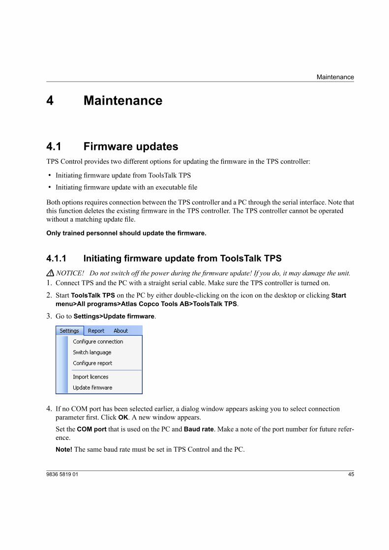
3. Go to Settings>Update firmware.
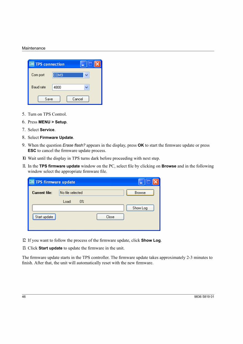
4. If no COM port has been selected earlier, a dialog window appears asking you to select connectionparameter first. Click OK. A new window appears.Set the COM port that is used on the PC and Baud rate. Make a note of the port number for future refer-ence.Note! The same baud rate must be set in TPS Control and the PC.
459836 5819 01
Maintenance
5. Turn on TPS Control.6. Press MENU > Setup.
7. Select Service.8. Select Firmware Update.
9. When the question Erase flash? appears in the display, press OK to start the firmware update or pressESC to cancel the firmware update process.
10. Wait until the display in TPS turns dark before proceeding with next step.
11. In the TPS firmware update window on the PC, select file by clicking on Browse and in the followingwindow select the appropriate firmware file.
12. If you want to follow the process of the firmware update, click Show Log.
13. Click Start update to update the firmware in the unit.
The firmware update starts in the TPS controller. The firmware update takes approximately 2-3 minutes tofinish. After that, the unit will automatically reset with the new firmware.
9836 5819 0146
Maintenance

4.1.2 Initiating firmware update with an executable fileT NOTICE! Do not switch off the power during the firmware update! If you do, it may damage the unit.1. Store the files blprog.exe and TPS-Control-V500.hex in the same directory on the PC.2. Connect TPS and the PC with a serial cable.
3. Identify the COM port that is used on the PC. Make a note of the port number for future reference.
4. Turn on TPS Control.5. Press MENU > Setup.
6. Select Service.7. Select Firmware Update.
8. When the question Erase flash? appears in the display, press OK to start the firmware update or pressESC to cancel the firmware update process.
9. Wait until the display in TPS turns dark before proceeding with next step.
10. Double-click on the executable file named blprog.exe.11. Enter the number of the COM port you are using.
12. When the program asks for what files to program, either press enter if there is only one hex file or, if thereare multiple hex files, enter the full names of all of them.
The firmware update starts. It will take 2-3 minutes to finish updating. After that, the unit will automaticallyreset with the new firmware.
479836 5819 01
Maintenance

5 Reference
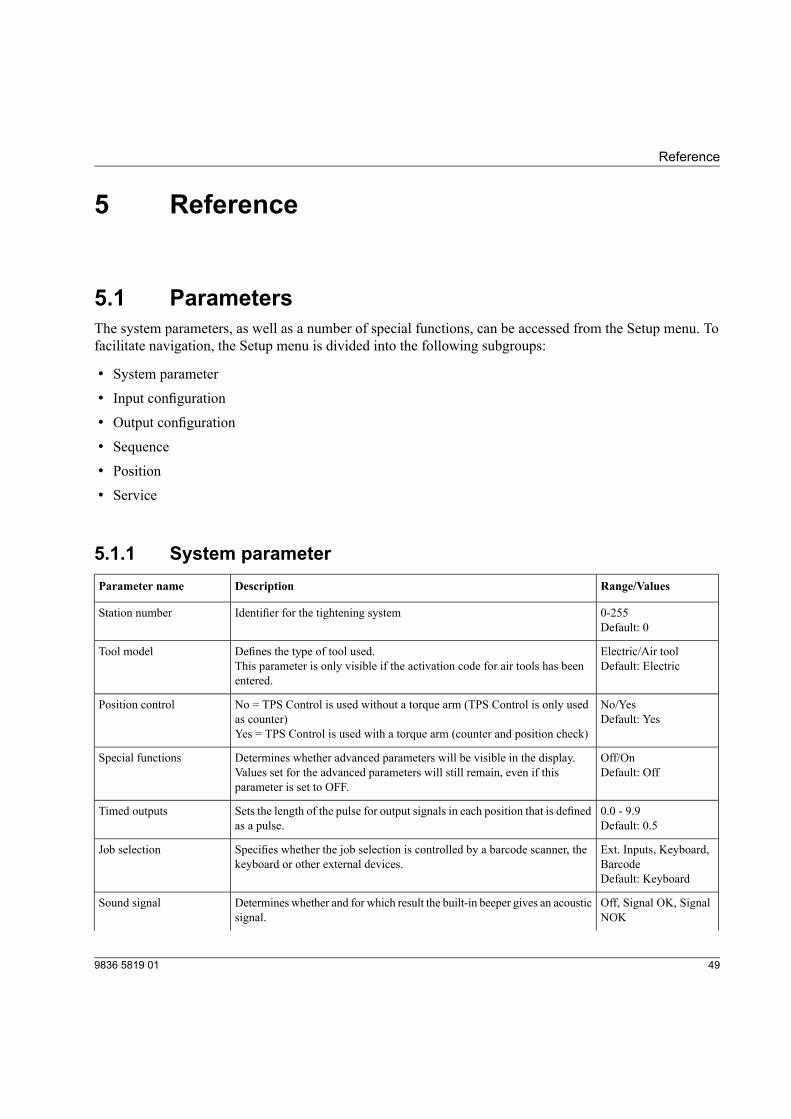
5.1 ParametersThe system parameters, as well as a number of special functions, can be accessed from the Setup menu. Tofacilitate navigation, the Setup menu is divided into the following subgroups:
• System parameter
• Input configuration
• Output configuration
• Sequence
• Position
• Service
5.1.1 System parameterRange/ValuesDescriptionParameter name
0-255Identifier for the tightening systemStation numberDefault: 0
Electric/Air toolDefines the type of tool used.Tool modelDefault: ElectricThis parameter is only visible if the activation code for air tools has been
entered.
No/YesNo = TPS Control is used without a torque arm (TPS Control is only usedas counter)
Position controlDefault: Yes
Yes = TPS Control is used with a torque arm (counter and position check)
Off/OnDetermines whether advanced parameters will be visible in the display.Values set for the advanced parameters will still remain, even if thisparameter is set to OFF.
Special functionsDefault: Off
0.0 - 9.9Sets the length of the pulse for output signals in each position that is definedas a pulse.
Timed outputsDefault: 0.5
Ext. Inputs, Keyboard,Barcode
Specifies whether the job selection is controlled by a barcode scanner, thekeyboard or other external devices.
Job selection
Default: Keyboard
Off, Signal OK, SignalNOK
Determines whether and for which result the built-in beeper gives an acousticsignal.
Sound signal
499836 5819 01
Reference
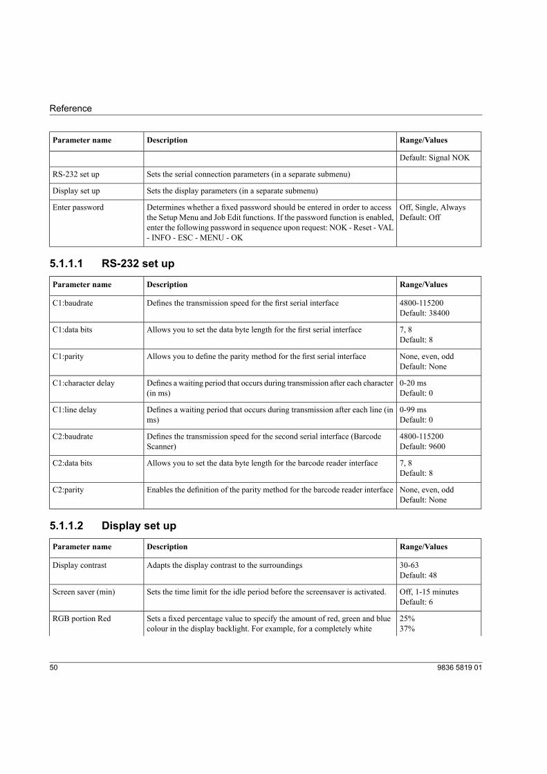
Range/ValuesDescriptionParameter name
Default: Signal NOK
Sets the serial connection parameters (in a separate submenu)RS-232 set up
Sets the display parameters (in a separate submenu)Display set up
Off, Single, AlwaysDetermines whether a fixed password should be entered in order to accessthe Setup Menu and Job Edit functions. If the password function is enabled,
Enter passwordDefault: Off
enter the following password in sequence upon request: NOK - Reset - VAL- INFO - ESC - MENU - OK
5.1.1.1 RS-232 set up
Range/ValuesDescriptionParameter name
4800-115200Defines the transmission speed for the first serial interfaceC1:baudrateDefault: 38400
7, 8Allows you to set the data byte length for the first serial interfaceC1:data bitsDefault: 8
None, even, oddAllows you to define the parity method for the first serial interfaceC1:parityDefault: None
0-20 msDefines a waiting period that occurs during transmission after each character(in ms)
C1:character delayDefault: 0
0-99 msDefines a waiting period that occurs during transmission after each line (inms)
C1:line delayDefault: 0
4800-115200Defines the transmission speed for the second serial interface (BarcodeScanner)
C2:baudrateDefault: 9600
7, 8Allows you to set the data byte length for the barcode reader interfaceC2:data bitsDefault: 8
None, even, oddEnables the definition of the parity method for the barcode reader interfaceC2:parityDefault: None
5.1.1.2 Display set up
Range/ValuesDescriptionParameter name
30-63Adapts the display contrast to the surroundingsDisplay contrastDefault: 48
Off, 1-15 minutesSets the time limit for the idle period before the screensaver is activated.Screen saver (min)Default: 6
25%Sets a fixed percentage value to specify the amount of red, green and bluecolour in the display backlight. For example, for a completely white
RGB portion Red37%
9836 5819 0150
Reference
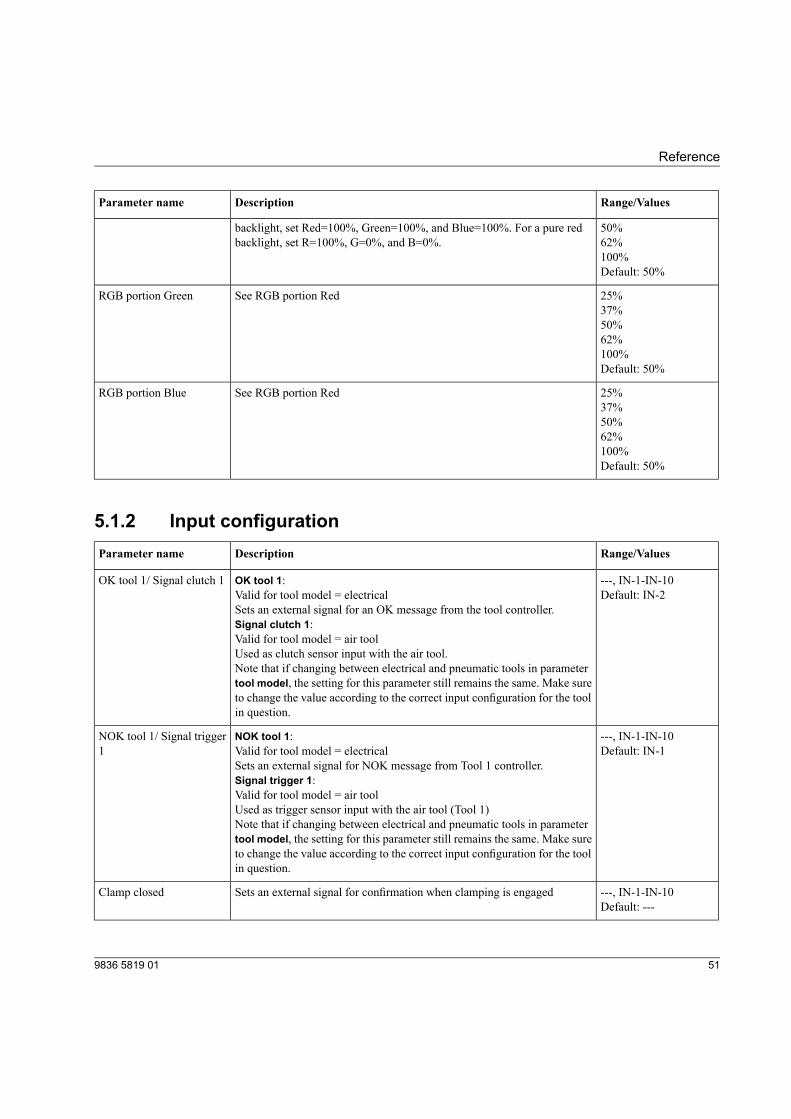
Range/ValuesDescriptionParameter name
50%backlight, set Red=100%, Green=100%, and Blue=100%. For a pure redbacklight, set R=100%, G=0%, and B=0%. 62%
100%Default: 50%
25%See RGB portion RedRGB portion Green37%50%62%100%Default: 50%
25%See RGB portion RedRGB portion Blue37%50%62%100%Default: 50%
5.1.2 Input configurationRange/ValuesDescriptionParameter name
---, IN-1-IN-10OK tool 1:OK tool 1/ Signal clutch 1Default: IN-2Valid for tool model = electrical
Sets an external signal for an OK message from the tool controller.Signal clutch 1:Valid for tool model = air toolUsed as clutch sensor input with the air tool.Note that if changing between electrical and pneumatic tools in parametertool model, the setting for this parameter still remains the same. Make sureto change the value according to the correct input configuration for the toolin question.
---, IN-1-IN-10NOK tool 1:NOK tool 1/ Signal trigger1 Default: IN-1Valid for tool model = electrical
Sets an external signal for NOK message from Tool 1 controller.Signal trigger 1:Valid for tool model = air toolUsed as trigger sensor input with the air tool (Tool 1)Note that if changing between electrical and pneumatic tools in parametertool model, the setting for this parameter still remains the same. Make sureto change the value according to the correct input configuration for the toolin question.
---, IN-1-IN-10Sets an external signal for confirmation when clamping is engagedClamp closedDefault: ---
519836 5819 01
Reference
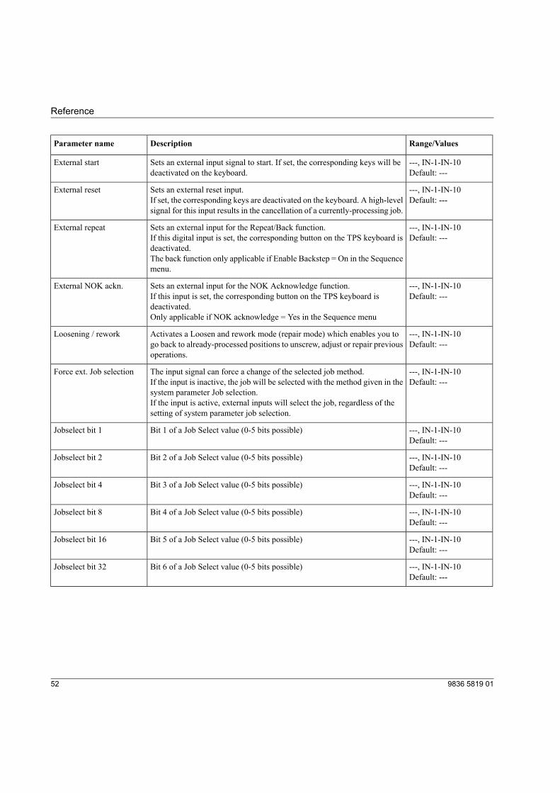
Range/ValuesDescriptionParameter name
---, IN-1-IN-10Sets an external input signal to start. If set, the corresponding keys will bedeactivated on the keyboard.
External startDefault: ---
---, IN-1-IN-10Sets an external reset input.External resetDefault: ---If set, the corresponding keys are deactivated on the keyboard. A high-level
signal for this input results in the cancellation of a currently-processing job.
---, IN-1-IN-10Sets an external input for the Repeat/Back function.External repeatDefault: ---If this digital input is set, the corresponding button on the TPS keyboard is
deactivated.The back function only applicable if Enable Backstep = On in the Sequencemenu.
---, IN-1-IN-10Sets an external input for the NOK Acknowledge function.External NOK ackn.Default: ---If this input is set, the corresponding button on the TPS keyboard is
deactivated.Only applicable if NOK acknowledge = Yes in the Sequence menu
---, IN-1-IN-10Activates a Loosen and rework mode (repair mode) which enables you togo back to already-processed positions to unscrew, adjust or repair previousoperations.
Loosening / reworkDefault: ---
---, IN-1-IN-10The input signal can force a change of the selected job method.Force ext. Job selectionDefault: ---If the input is inactive, the job will be selected with the method given in the
system parameter Job selection.If the input is active, external inputs will select the job, regardless of thesetting of system parameter job selection.
---, IN-1-IN-10Bit 1 of a Job Select value (0-5 bits possible)Jobselect bit 1Default: ---
---, IN-1-IN-10Bit 2 of a Job Select value (0-5 bits possible)Jobselect bit 2Default: ---
---, IN-1-IN-10Bit 3 of a Job Select value (0-5 bits possible)Jobselect bit 4Default: ---
---, IN-1-IN-10Bit 4 of a Job Select value (0-5 bits possible)Jobselect bit 8Default: ---
---, IN-1-IN-10Bit 5 of a Job Select value (0-5 bits possible)Jobselect bit 16Default: ---
---, IN-1-IN-10Bit 6 of a Job Select value (0-5 bits possible)Jobselect bit 32Default: ---
9836 5819 0152
Reference
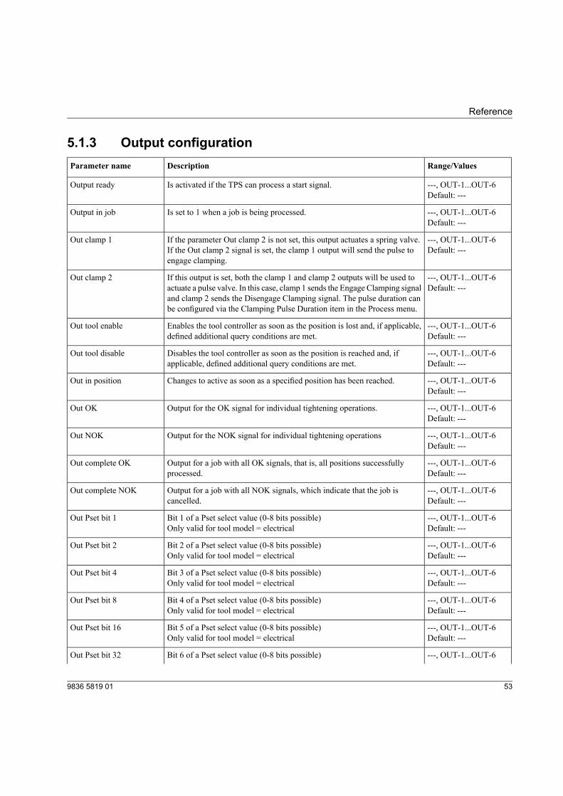
5.1.3 Output configurationRange/ValuesDescriptionParameter name
---, OUT-1...OUT-6Is activated if the TPS can process a start signal.Output readyDefault: ---
---, OUT-1...OUT-6Is set to 1 when a job is being processed.Output in jobDefault: ---
---, OUT-1...OUT-6If the parameter Out clamp 2 is not set, this output actuates a spring valve.If the Out clamp 2 signal is set, the clamp 1 output will send the pulse toengage clamping.
Out clamp 1Default: ---
---, OUT-1...OUT-6If this output is set, both the clamp 1 and clamp 2 outputs will be used toactuate a pulse valve. In this case, clamp 1 sends the Engage Clamping signal
Out clamp 2Default: ---
and clamp 2 sends the Disengage Clamping signal. The pulse duration canbe configured via the Clamping Pulse Duration item in the Process menu.
---, OUT-1...OUT-6Enables the tool controller as soon as the position is lost and, if applicable,defined additional query conditions are met.
Out tool enableDefault: ---
---, OUT-1...OUT-6Disables the tool controller as soon as the position is reached and, ifapplicable, defined additional query conditions are met.
Out tool disableDefault: ---
---, OUT-1...OUT-6Changes to active as soon as a specified position has been reached.Out in positionDefault: ---
---, OUT-1...OUT-6Output for the OK signal for individual tightening operations.Out OKDefault: ---
---, OUT-1...OUT-6Output for the NOK signal for individual tightening operationsOut NOKDefault: ---
---, OUT-1...OUT-6Output for a job with all OK signals, that is, all positions successfullyprocessed.
Out complete OKDefault: ---
---, OUT-1...OUT-6Output for a job with all NOK signals, which indicate that the job iscancelled.
Out complete NOKDefault: ---
---, OUT-1...OUT-6Bit 1 of a Pset select value (0-8 bits possible)Out Pset bit 1Default: ---Only valid for tool model = electrical
---, OUT-1...OUT-6Bit 2 of a Pset select value (0-8 bits possible)Out Pset bit 2Default: ---Only valid for tool model = electrical
---, OUT-1...OUT-6Bit 3 of a Pset select value (0-8 bits possible)Out Pset bit 4Default: ---Only valid for tool model = electrical
---, OUT-1...OUT-6Bit 4 of a Pset select value (0-8 bits possible)Out Pset bit 8Default: ---Only valid for tool model = electrical
---, OUT-1...OUT-6Bit 5 of a Pset select value (0-8 bits possible)Out Pset bit 16Default: ---Only valid for tool model = electrical
---, OUT-1...OUT-6Bit 6 of a Pset select value (0-8 bits possible)Out Pset bit 32
539836 5819 01
Reference
Range/ValuesDescriptionParameter name
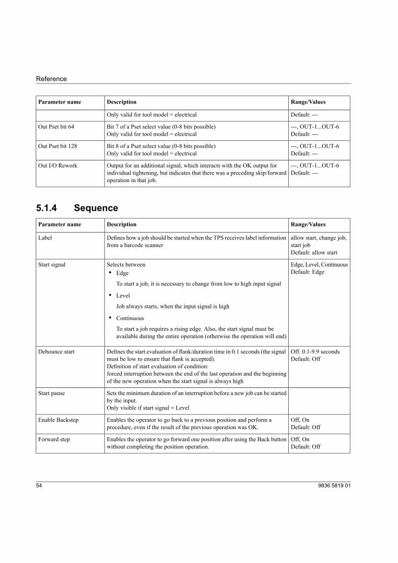
Default: ---Only valid for tool model = electrical
---, OUT-1...OUT-6Bit 7 of a Pset select value (0-8 bits possible)Out Pset bit 64Default: ---Only valid for tool model = electrical
---, OUT-1...OUT-6Bit 8 of a Pset select value (0-8 bits possible)Out Pset bit 128Default: ---Only valid for tool model = electrical
---, OUT-1...OUT-6Output for an additional signal, which interacts with the OK output forindividual tightening, but indicates that there was a preceding skip/forwardoperation in that job.
Out I/O ReworkDefault: ---
5.1.4 SequenceRange/ValuesDescriptionParameter name
allow start, change job,start job
Defines how a job should be started when the TPS receives label informationfrom a barcode scanner
Label
Default: allow start
Edge, Level, ContinuousSelects betweenStart signalDefault: Edge• Edge
To start a job, it is necessary to change from low to high input signal
• Level
Job always starts, when the input signal is high
• Continuous
To start a job requires a rising edge. Also, the start signal must beavailable during the entire operation (otherwise the operation will end)
Off. 0.1-9.9 secondsDefines the start evaluation of flank/duration time in 0.1 seconds (the signalmust be low to ensure that flank is accepted).
Debounce startDefault: Off
Definition of start evaluation of condition:forced interruption between the end of the last operation and the beginningof the new operation when the start signal is always high
Sets the minimum duration of an interruption before a new job can be startedby the input.
Start pause
Only visible if start signal = Level
Off, OnEnables the operator to go back to a previous position and perform aprocedure, even if the result of the previous operation was OK.
Enable BackstepDefault: Off
Off, OnEnables the operator to go forward one position after using the Back buttonwithout completing the position operation.
Forward stepDefault: Off
9836 5819 0154
Reference
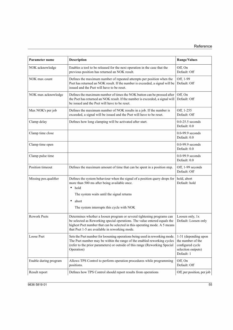
Range/ValuesDescriptionParameter name
Off, OnEnables a tool to be released for the next operation in the case that theprevious position has returned an NOK result.
NOK acknowledgeDefault: Off
Off, 1-99Defines the maximum number of repeated attempts per position when thePset has returned an NOK result. If the number is exceeded, a signal will beissued and the Pset will have to be reset.
NOK max countDefault: Off
Off, OnDefines the maximum number of times the NOK button can be pressed afterthe Pset has returned an NOK result. If the number is exceeded, a signal willbe issued and the Pset will have to be reset.
NOK max acknowledgeDefault: Off
Off, 1-255Defines the maximum number of NOK results in a job. If the number isexceeded, a signal will be issued and the Pset will have to be reset.
Max NOK's per jobDefault: Off
0.0-25.5 secondsDefines how long clamping will be activated after start.Clamp delayDefault: 0.0
0.0-99.9 secondsClamp time closeDefault: 0.0
0.0-99.9 secondsClamp time openDefault: 0.0
0.0-99.9 secondsClamp pulse timeDefault: 0.0
Off, 1-99 secondsDefines the maximum amount of time that can be spent in a position step.Position timeoutDefault: Off
hold, abortDefines the system behaviour when the signal of a position query drops formore than 500 ms after being available once.
Missing pos.qualifierDefault: hold
• hold
The system waits until the signal returns
• abort
The system interrupts this cycle with NOK
Loosen only, 1xDetermines whether a loosen program or several tightening programs canbe selected as Reworking special operations. The value entered equals the
Rework PsetsDefault: Loosen only
highest Pset number that can be selected in this operating mode. A 5 meansthat Pset 1-5 are available in reworking mode.
1-31 (depending uponthe number of the
Sets the Pset number for loosening operations being used in reworkingmode.The Pset number may be within the range of the enabled reworking cycles
Loose Pset
configured cycleselection outputs)
(refer to the prior parameters) or outside of this range (Reworking SpecialOperation)
Default: 1
Off, OnAllows TPS Control to perform operation procedures while programmingpositions.
Enable during programDefault: Off
Off, per position, per jobDefines how TPS Control should report results from operationsResult report
559836 5819 01
Reference
Range/ValuesDescriptionParameter name
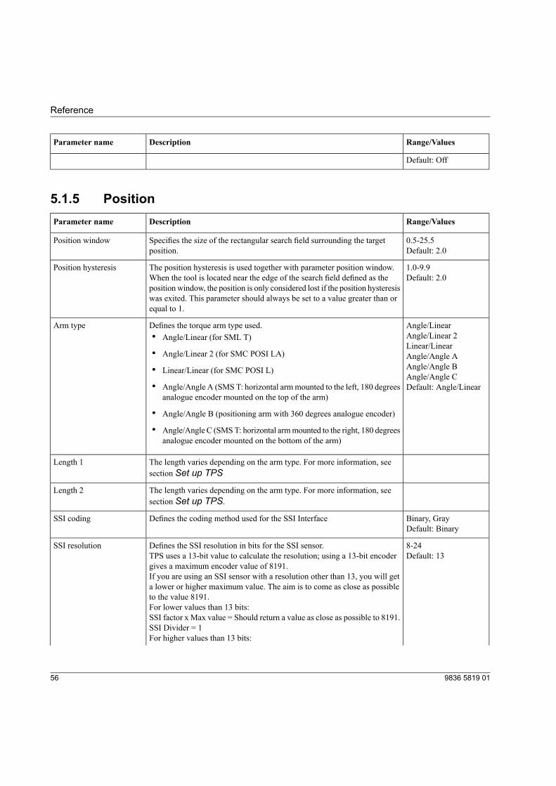
Default: Off
5.1.5 PositionRange/ValuesDescriptionParameter name
0.5-25.5Specifies the size of the rectangular search field surrounding the targetposition.
Position windowDefault: 2.0
1.0-9.9The position hysteresis is used together with parameter position window.When the tool is located near the edge of the search field defined as the
Position hysteresisDefault: 2.0
position window, the position is only considered lost if the position hysteresiswas exited. This parameter should always be set to a value greater than orequal to 1.
Angle/LinearDefines the torque arm type used.Arm typeAngle/Linear 2• Angle/Linear (for SML T)Linear/Linear
• Angle/Linear 2 (for SMC POSI LA) Angle/Angle AAngle/Angle B• Linear/Linear (for SMC POSI L)Angle/Angle C
• Angle/Angle A (SMS T: horizontal armmounted to the left, 180 degreesanalogue encoder mounted on the top of the arm)
Default: Angle/Linear
• Angle/Angle B (positioning arm with 360 degrees analogue encoder)
• Angle/Angle C (SMST: horizontal armmounted to the right, 180 degreesanalogue encoder mounted on the bottom of the arm)
The length varies depending on the arm type. For more information, seesection Set up TPS
Length 1
The length varies depending on the arm type. For more information, seesection Set up TPS.
Length 2
Binary, GrayDefines the coding method used for the SSI InterfaceSSI codingDefault: Binary
8-24Defines the SSI resolution in bits for the SSI sensor.SSI resolutionDefault: 13TPS uses a 13-bit value to calculate the resolution; using a 13-bit encoder
gives a maximum encoder value of 8191.If you are using an SSI sensor with a resolution other than 13, you will geta lower or higher maximum value. The aim is to come as close as possibleto the value 8191.For lower values than 13 bits:SSI factor x Max value = Should return a value as close as possible to 8191.SSI Divider = 1For higher values than 13 bits:
9836 5819 0156
Reference
Range/ValuesDescriptionParameter name
SSI factor = 1Max value / SSI Divider = Should return a value as close as possible to 8191.
1-99See SSI resolution for explanationSSI factorDefault: 1
1, 2, 4, 8, 16, 32, 64,128
See SSI resolution for explanationSSI Divider
Default: 1
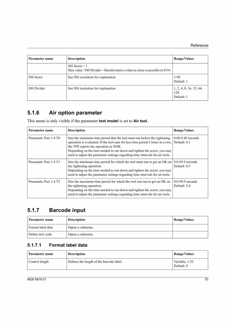
5.1.6 Air option parameterThis menu is only visible if the parameter tool model is set to Air tool..
Range/ValuesDescriptionParameter name
0.00-0.40 secondsSets the minimum time period that the tool must run before the tighteningoperation is evaluated. If the tool runs for less time period 2 times in a row,the TPS reports the operation as NOK.
Pneumatic Pset 1-4 T0Default: 0.1
Depending on the time needed to run down and tighten the screw, you mayneed to adjust the parameter settings regarding time intervals for air tools.
0.0-99.9 secondsSets the minimum time period for which the tool must run to get an OK onthe tightening operation.
Pneumatic Pset 1-4 T1Default: 0.5
Depending on the time needed to run down and tighten the screw, you mayneed to adjust the parameter settings regarding time intervals for air tools.
0.0-99.9 secondsSets the maximum time period for which the tool can run to get an OK onthe tightening operation.
Pneumatic Pset 1-4 T2Default: 2.0
Depending on the time needed to run down and tighten the screw, you mayneed to adjust the parameter settings regarding time intervals for air tools.
5.1.7 Barcode inputRange/ValuesDescriptionParameter name
Opens a submenu.Format label data
Opens a submenu.Define new code
5.1.7.1 Format label data
Range/ValuesDescriptionParameter name
Variable, 1-53Defines the length of the barcode label.Control lengthDefault: 8
579836 5819 01
Reference
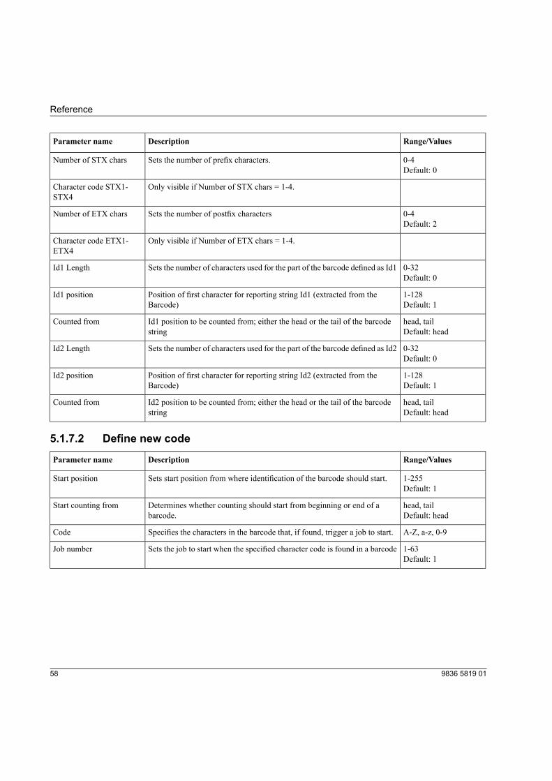
Range/ValuesDescriptionParameter name
0-4Sets the number of prefix characters.Number of STX charsDefault: 0
Only visible if Number of STX chars = 1-4.Character code STX1-STX4
0-4Sets the number of postfix charactersNumber of ETX charsDefault: 2
Only visible if Number of ETX chars = 1-4.Character code ETX1-ETX4
0-32Sets the number of characters used for the part of the barcode defined as Id1Id1 LengthDefault: 0
1-128Position of first character for reporting string Id1 (extracted from theBarcode)
Id1 positionDefault: 1
head, tailId1 position to be counted from; either the head or the tail of the barcodestring
Counted fromDefault: head
0-32Sets the number of characters used for the part of the barcode defined as Id2Id2 LengthDefault: 0
1-128Position of first character for reporting string Id2 (extracted from theBarcode)
Id2 positionDefault: 1
head, tailId2 position to be counted from; either the head or the tail of the barcodestring
Counted fromDefault: head
5.1.7.2 Define new code
Range/ValuesDescriptionParameter name
1-255Sets start position from where identification of the barcode should start.Start positionDefault: 1
head, tailDetermines whether counting should start from beginning or end of abarcode.
Start counting fromDefault: head
A-Z, a-z, 0-9Specifies the characters in the barcode that, if found, trigger a job to start.Code
1-63Sets the job to start when the specified character code is found in a barcodeJob numberDefault: 1
9836 5819 0158
Reference
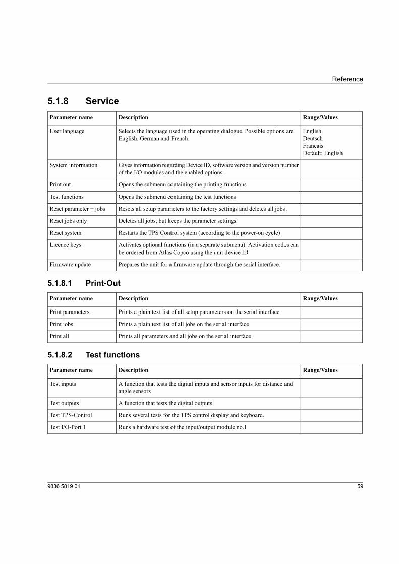
5.1.8 ServiceRange/ValuesDescriptionParameter name
EnglishSelects the language used in the operating dialogue. Possible options areEnglish, German and French.
User languageDeutschFrancaisDefault: English
Gives information regardingDevice ID, software version and version numberof the I/O modules and the enabled options
System information
Opens the submenu containing the printing functionsPrint out
Opens the submenu containing the test functionsTest functions
Resets all setup parameters to the factory settings and deletes all jobs.Reset parameter + jobs
Deletes all jobs, but keeps the parameter settings.Reset jobs only
Restarts the TPS Control system (according to the power-on cycle)Reset system
Activates optional functions (in a separate submenu). Activation codes canbe ordered from Atlas Copco using the unit device ID
Licence keys
Prepares the unit for a firmware update through the serial interface.Firmware update
5.1.8.1 Print-Out
Range/ValuesDescriptionParameter name
Prints a plain text list of all setup parameters on the serial interfacePrint parameters
Prints a plain text list of all jobs on the serial interfacePrint jobs
Prints all parameters and all jobs on the serial interfacePrint all
5.1.8.2 Test functions
Range/ValuesDescriptionParameter name
A function that tests the digital inputs and sensor inputs for distance andangle sensors
Test inputs
A function that tests the digital outputsTest outputs
Runs several tests for the TPS control display and keyboard.Test TPS-Control
Runs a hardware test of the input/output module no.1Test I/O-Port 1
599836 5819 01
Reference
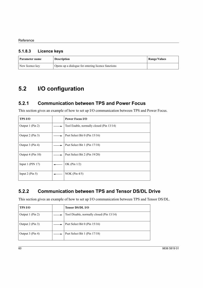
5.1.8.3 Licence keys
Range/ValuesDescriptionParameter name
Opens up a dialogue for entering licence functionsNew licence key
5.2 I/O configuration
5.2.1 Communication between TPS and Power FocusThis section gives an example of how to set up I/O communication between TPS and Power Focus.
Power Focus I/OTPS I/O
Tool Enable, normally closed (Pin 13/14)Output 1 (Pin 2)
Pset Select Bit 0 (Pin 15/16)Output 2 (Pin 3)
Pset Select Bit 1 (Pin 17/18)Output 3 (Pin 4)
Pset Select Bit 2 (Pin 19/20)Output 4 (Pin 10)
OK (Pin 1/2)Input 1 (PIN 17)
NOK (Pin 4/5)Input 2 (Pin 5)
5.2.2 Communication between TPS and Tensor DS/DL DriveThis section gives an example of how to set up I/O communication between TPS and Tensor DS/DL.
Tensor DS/DL I/OTPS I/O
Tool Disable, normally closed (Pin 13/14)Output 1 (Pin 2)
Pset Select Bit 0 (Pin 15/16)Output 2 (Pin 3)
Pset Select Bit 1 (Pin 17/18)Output 3 (Pin 4)
9836 5819 0160
Reference
Tensor DS/DL I/OTPS I/O
Pset Select Bit 2 (Pin 19/20)Output 4 (Pin 10)
OK (Pin 1/2)Input 1 (PIN 17)
NOK (Pin 4/5)Input 2 (Pin 5)
5.2.3 Communication between TPS and MicroTorque G4This section gives an example of how to set up I/O communication between TPS and MicroTorque G4.
MicroTorque G4 I/OTPS I/O
Disable (Pin 20)Output 1 (Pin 2)
Pset Select Bit 0 (Pin 15)Output 2 (Pin 3)
Pset Select Bit 1 (Pin 16)Output 3 (Pin 4)
Pset Select Bit 2 (Pin 17)Output 4 (Pin 10)
OK (Pin 5)Input 1 (PIN 17)
NOK (Pin 6)Input 2 (Pin 5)
5.2.4 Communication between TPS and MicroTorque Focus 400This section gives an example of how to set up I/O communication between TPS and MicroTorque Focus400.
MicroTorque Focus I/OTPS I/O
Tool Disable (Pin 8)Output 1 (Pin 2)
Pset Select Bit 0 (Pin 9)Output 2 (Pin 3)
Pset Select Bit 1 (Pin 10)Output 3 (Pin 4)
619836 5819 01
Reference
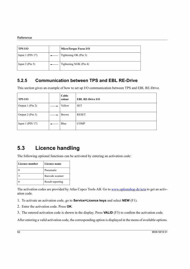
MicroTorque Focus I/OTPS I/O
Tightening OK (Pin 3)Input 1 (PIN 17)
Tightening NOK (Pin 4)Input 2 (Pin 5)
5.2.5 Communication between TPS and EBL RE-DriveThis section gives an example of how to set up I/O communication between TPS and EBL RE-Drive.
EBL RE-Drive I/OCablecolourTPS I/O
SETYellowOutput 1 (Pin 2)
RESETBrownOutput 2 (Pin 3)
COMPBlueInput 1 (PIN 17)
5.3 Licence handlingThe following optional functions can be activated by entering an activation code:
Licence nameLicence number
Pneumatic0
Barcode scanner3
Result reporting6
The activation codes are provided by Atlas Copco Tools AB. Go to www.optionshop.de/acta to get an activ-ation code.
1. To activate an activation code, go to Service>Licence keys and select NEW (F1).
2. Enter the activation code. Press OK.3. The entered activation code is shown in the display. Press VALID (F3) to confirm the activation code.
After entering a valid activation code, the corresponding option is displayed in the menu of available options.
9836 5819 0162
Reference
Any available option can be temporarily deactivated by placing the bar cursor on the appropriate option withthe up/down arrow keys and pressing ON-OFF (F2). A [--] flag appears beside a deactivated option. Repeatingthe process reactivates the option.
DELETE completely removes the option. To re-enable the option, the enabling code must be re-entered.
To see which licensed functions have been activated, go to Service>System information.The parameterOptions lists the available licence numbers.
5.4 Pneumatic functionTPS Control can be used with a pneumatic system for evaluating the OK/NOK for each individual tighteningoperation. This is done using a double sensor system (with digital inputs) connected to the air tool. In additionto positioning, TPS Control counts all correct tightenings in a batch and detects for example premature shut-off, stripped threads and wrong screw length.
To set up I/O communication between TPS and the air tool, see section Connect TPS to tool control systems.
5.4.1 Licensed functionThe pneumatic function is an optional licensed function. To activate the licence for air tools, see section Li-cence handling.
5.4.2 Pneumatic monitoring and controllingAir tools with reporting functionality are equipped with a pneumatic signal output that indicates which phaseof the tightening cycle the tool has reached, by means of variations in air pressure (see figure below). Thepneumatic signal is located between the start valve and the shutoff valve of the driver and is carried througha small signal tube to two external pressure sensors. The pressure sensors produce digital signals used forcontrolling the air supply to the tool using a magnetic valve.
For TPS Control to function properly with air tools, it requires a stable air-line system without too muchpressure fluctuations. You must therefore install a pressure gauge as close as possible to the TPS pneumaticsystem and for an optimal air signal, make sure the air cable length is no more than two meters.
To get significant pressure value difference between different tightening sequences, make sure that there areno leakages in the couplings and tubes.
639836 5819 01
Reference
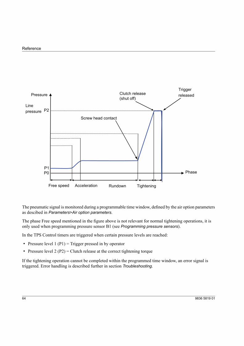
Pressure
Line
pressure
Rundown
Clutch release
(shut off)
Trigger
released
Screw head contact
Tightening
Free speed Acceleration
Phase
P2
P1
P0
The pneumatic signal is monitored during a programmable time window, defined by the air option parametersas descibed in Parameters>Air option parameters.
The phase Free speed mentioned in the figure above is not relevant for normal tightening operations, it isonly used when programming pressure sensor B1 (see Programming pressure sensors).
In the TPS Control timers are triggered when certain pressure levels are reached:
• Pressure level 1 (P1) = Trigger pressed in by operator
• Pressure level 2 (P2) = Clutch release at the correct tightening torque
If the tightening operation cannot be completed within the programmed time window, an error signal istriggered. Error handling is described further in section Troubleshooting.
9836 5819 0164
Reference
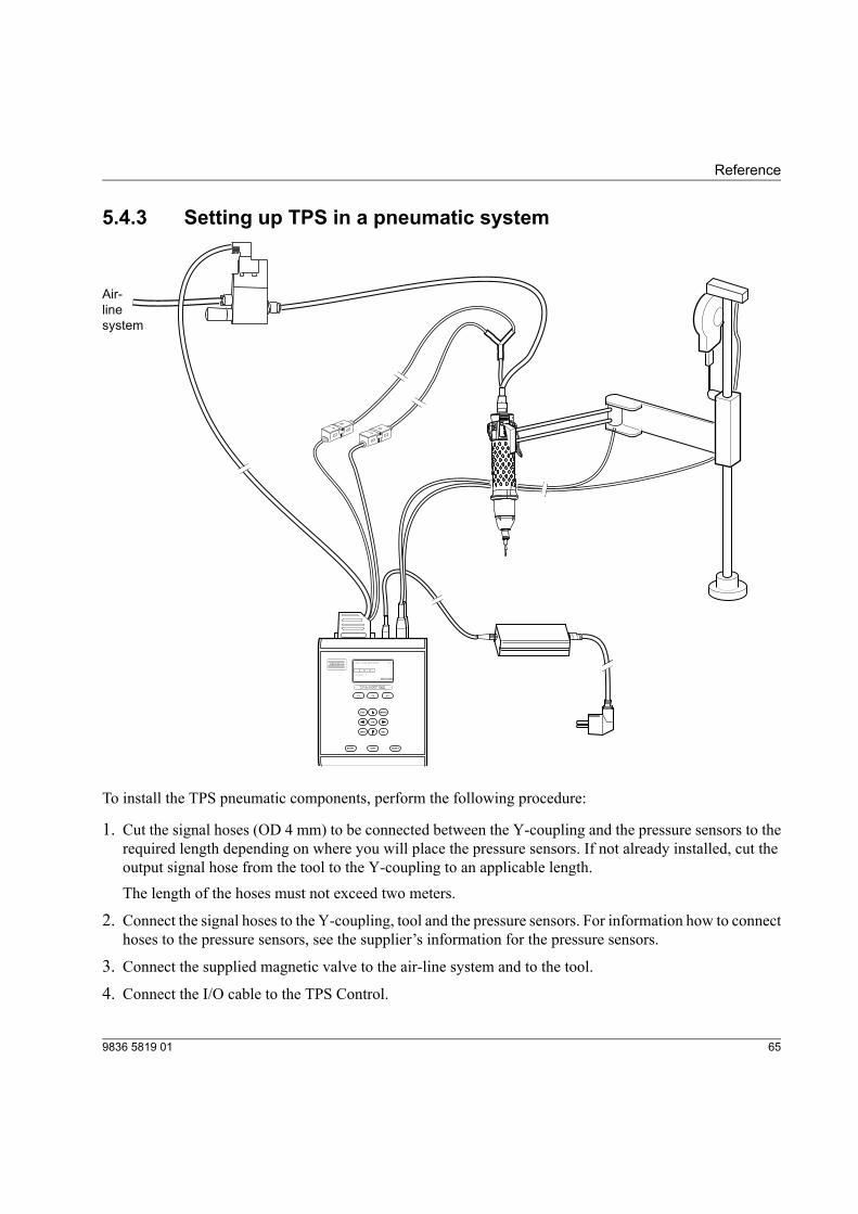
5.4.3 Setting up TPS in a pneumatic system
Edit
Edit
Air-
line
system
F1
ESC MENU
INFO
START NOK RESET
VAL
OK
F2 F3
J04: JOB.MOTOR P1
Cycle: 1
1
RESET
2 3 4
To install the TPS pneumatic components, perform the following procedure:
1. Cut the signal hoses (OD 4 mm) to be connected between the Y-coupling and the pressure sensors to therequired length depending on where you will place the pressure sensors. If not already installed, cut theoutput signal hose from the tool to the Y-coupling to an applicable length.The length of the hoses must not exceed two meters.
2. Connect the signal hoses to the Y-coupling, tool and the pressure sensors. For information how to connecthoses to the pressure sensors, see the supplier’s information for the pressure sensors.
3. Connect the supplied magnetic valve to the air-line system and to the tool.
4. Connect the I/O cable to the TPS Control.
659836 5819 01
Reference
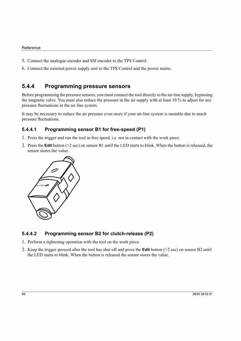
5. Connect the analogue encoder and SSI encoder to the TPS Control.6. Connect the external power supply unit to the TPS Control and the power mains.
5.4.4 Programming pressure sensorsBefore programming the pressure sensors, youmust connect the tool directly to the air-line supply, bypassingthe magnetic valve. You must also reduce the pressure in the air supply with at least 10 % to adjust for anypressure fluctuations in the air line system.
It may be necessary to reduce the air pressure even more if your air-line system is unstable due to muchpressure fluctuations.
5.4.4.1 Programming sensor B1 for free-speed (P1)1. Press the trigger and run the tool in free speed, i.e. not in contact with the work piece.2. Press the Edit button (>2 sec) on sensor B1 until the LED starts to blink. When the button is released, the
sensor stores the value.
Edit
5.4.4.2 Programming sensor B2 for clutch-release (P2)1. Perform a tightening operation with the tool on the work piece.
2. Keep the trigger pressed after the tool has shut off and press the Edit button (>2 sec) on sensor B2 untilthe LED starts to blink. When the button is released the sensor stores the value.
9836 5819 0166
Reference
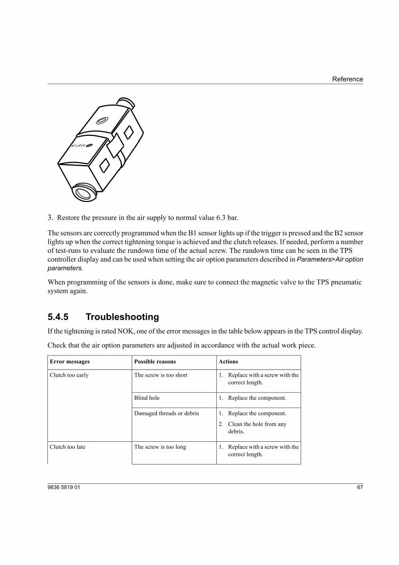
Edit
3. Restore the pressure in the air supply to normal value 6.3 bar.
The sensors are correctly programmedwhen the B1 sensor lights up if the trigger is pressed and the B2 sensorlights up when the correct tightening torque is achieved and the clutch releases. If needed, perform a numberof test-runs to evaluate the rundown time of the actual screw. The rundown time can be seen in the TPScontroller display and can be used when setting the air option parameters described in Parameters>Air optionparameters.
When programming of the sensors is done, make sure to connect the magnetic valve to the TPS pneumaticsystem again.
5.4.5 TroubleshootingIf the tightening is rated NOK, one of the error messages in the table below appears in the TPS control display.
Check that the air option parameters are adjusted in accordance with the actual work piece.
ActionsPossible reasonsError messages
The screw is too shortClutch too early 1. Replace with a screwwith thecorrect length.
Blind hole 1. Replace the component.
Damaged threads or debris 1. Replace the component.
2. Clean the hole from anydebris.
The screw is too longClutch too late 1. Replace with a screwwith thecorrect length.
679836 5819 01
Reference
ActionsPossible reasonsError messages
Damaged or worn threads 1. Replace faulty screw orcomponent.
Missing joint components, suchas a washer
1. Add the missing component
Trigger pressed twiceunintentionally
No clutch operation 1. Release trigger.
2. In TPS Control, press Resetto end operation
Trigger is released before correcttightening torque is achieved
1. In TPS Control, press Resetto end operation
5.5 Barcode function
5.5.1 Licensed functionThe barcode function is an optional licensed function. To activate the licence for air tools, see section Licencehandling.
5.5.2 DescriptionThe barcode function extends the TPS Control by connecting a barcode scanner to a second serial interfaceand carrying out the job selection with the read-in barcode.
The TPS Control has two RS-232 serial ports to connect the unit to a PC and a barcode reader. Since bothRS-232 interfaces are available on the same Sub-D 9-pin connector, a Y-cable adapter must be used if thebarcode scanner and the PC connection are to be used at the same time. For more information about cables,see the TPS instructions.
The barcode function allows TPS to read a barcode string with up to 255 characters using the scanner. Toensure secure identification of the start and end of a code, there are different parameters to set up the usedlabel format. The system can handle labels with a fixed length or a variable length.
The actual label characters can be prefixed or suffixed by additional STX or ETX character sequences. Theprefix can contain up to 4 characters (STX1-STX4). The postfix can also contain up to 4 characters (ETX1-ETX4). Prefix and postfix can both be omitted. The individual characters should be entered with their ASCII
9836 5819 0168
Reference

code. In case of a variable control length, an ETX sequence must be defined, so that the end of the label datacan be detected.
With many scanners, the STX sequence is empty and the ETX sequence consists of a CR-LF (Carriage Return,Line Feed) sequence. The CR, for example, has the ASCII code 13 and the LF the ASCII code 10.
The connected barcode scanner sends the read-in label automatically to the TPS Control.
For example, suppose you scan a label with variable length, no prefix and one postfix character (CR, carriagereturn = 13 decimal).
This will be transmitted by the scanner as
6159326580:10D1762186<CR>
The CR character is not part of the barcode, but is instead generated by the scanner. Typically, the scannercan be set up to have specific prefix and/or postfix characters.
If the first part of the barcode string (6159326580) is the part type, this could be used for selecting a specificjob. To specify jobs to different barcodes you will have to setup a barcode definition in the TPS system.
5.5.3 Barcode definition parametersThe system must be told which labels initiate a particular job. The entry of these numbers is carried out inthe parameter menu under the menu item Barcode input. Upon selecting this menu, the following windowappears:
699836 5819 01
Reference
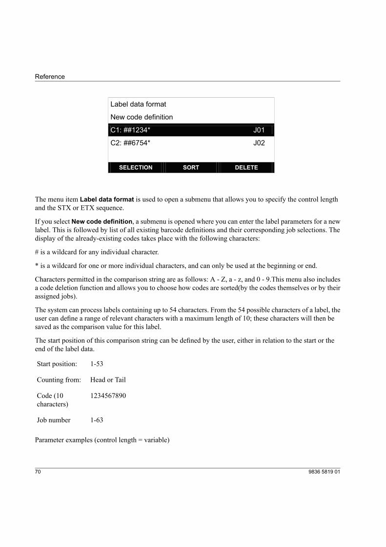
Label data format
New code definition
C1: ##1234* J01
C2: ##6754* J02
SELECTION SORT DELETE
The menu item Label data format is used to open a submenu that allows you to specify the control lengthand the STX or ETX sequence.
If you select New code definition, a submenu is opened where you can enter the label parameters for a newlabel. This is followed by list of all existing barcode definitions and their corresponding job selections. Thedisplay of the already-existing codes takes place with the following characters:
# is a wildcard for any individual character.
* is a wildcard for one or more individual characters, and can only be used at the beginning or end.
Characters permitted in the comparison string are as follows: A - Z, a - z, and 0 - 9.This menu also includesa code deletion function and allows you to choose how codes are sorted(by the codes themselves or by theirassigned jobs).
The system can process labels containing up to 54 characters. From the 54 possible characters of a label, theuser can define a range of relevant characters with a maximum length of 10; these characters will then besaved as the comparison value for this label.
The start position of this comparison string can be defined by the user, either in relation to the start or theend of the label data.
1-53Start position:
Head or TailCounting from:
1234567890Code (10characters)
1-63Job number
Parameter examples (control length = variable)
9836 5819 0170
Reference
Start position 1, counting from head Code: 123 Job number: 10
With these parameters, all labels starting with the characters 123 would select Job 10. Display in overviewmenu: Cx: 123*
Start position 4, counting from head, Code: 78, Job number: 3
With these parameters, all labels with a 7 as the 4th character and an 8 as the 5th character would select Job3.
Display in overview menu: Cx: ###78*
Depending on whether the system is equipped with or uses Start/end sequence processing, the label musteither be read in before the start (without Start sequence use), or at the end of the start sequence so that thesystem can select the assigned job.
By setting the parameter Label in the menu Sequence it can be determined whether a new label must beread in for every start, or if the previous job selection will continue when starting without a new label.
A read-in label will be shown in the display of the TPS Control if it cannot be processed. A total of 200 labelscan be used in TPS Control.
All label data can also be printed out with the Print function.
5.6 Reporting function
5.6.1 Licensed functionThe result reporting function is an optional licensed function and is activated with an activation code. SectionLicence handling describes how to activate licensed functions.
5.6.2 DescriptionYou can select between the following result reports:
• Position reportGives a result for every tightening position. If a Job has five tightening positions, a separate report foreach position is generated as well as a result report for the complete job.
• Job reportGives one result report for the complete job.
719836 5819 01
Reference
5.6.3 ProcedureTo activate result reporting, perform the following procedure:
1. Press Setup>Sequence.2. Select parameter Result Report and press OK.3. Select if to activate a position report or job report. To deactivate function, select option Off.4. Press VAL to confirm the selected option.
5.7 Printout1. Connect TPS Control to a PC using the RS-232 interface.
2. In TPS Control, go to RS-232 setup and set parameter C1:baudrate.Note! The same baud rate must be used in TPS Control and the PC.
3. On the PC, select All programs>Accessories>Communications>HyperTerminal from the start menu.A new window will appear.
4. Enter a name for the communication with TPS and click OK. A new window will appear.
5. Click Cancel. The HyperTerminal window will appear.
6. Click Call in the HyperTerminal window. A new window will appear.
9836 5819 0172
Reference
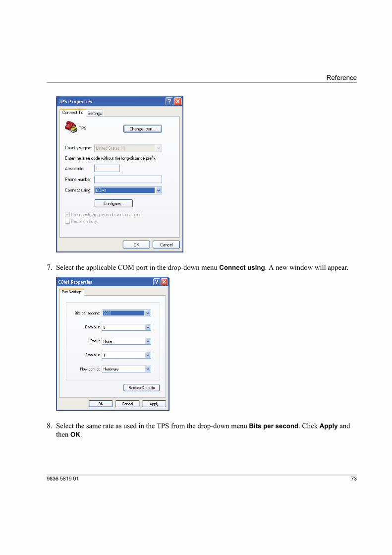
7. Select the applicable COM port in the drop-down menu Connect using. A new window will appear.
8. Select the same rate as used in the TPS from the drop-down menu Bits per second. Click Apply andthen OK.
739836 5819 01
Reference
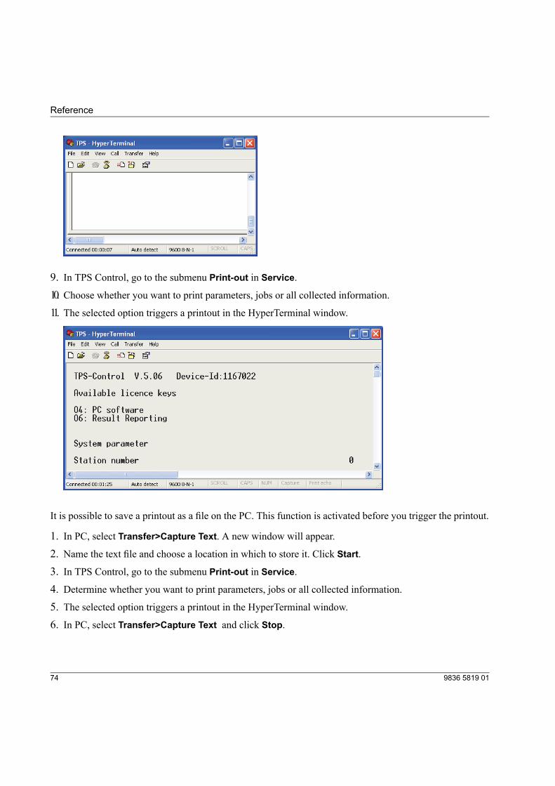
9. In TPS Control, go to the submenu Print-out in Service.10. Choose whether you want to print parameters, jobs or all collected information.11. The selected option triggers a printout in the HyperTerminal window.
It is possible to save a printout as a file on the PC. This function is activated before you trigger the printout.
1. In PC, select Transfer>Capture Text. A new window will appear.
2. Name the text file and choose a location in which to store it. Click Start.3. In TPS Control, go to the submenu Print-out in Service.4. Determine whether you want to print parameters, jobs or all collected information.5. The selected option triggers a printout in the HyperTerminal window.6. In PC, select Transfer>Capture Text and click Stop.
9836 5819 0174
Reference


9836 5819 01Edition 1.22014-03
www.atlascopco.com


