1628
Abstract An accurate coupled field piezoelectric beam finite element formu-lation is presented. The formulation is based on First-order Shear Deformation Theory (FSDT) with layerwise electric potential. An appropriate through-thickness electric potential distribution is derived using electrostatic equilibrium equations, unlike conven-tional FSDT based formulations which use assumed independent layerwise linear potential distribution. The derived quadratic potential consists of a coupled term which takes care of induced potential and the associated change in stiffness, without bringing in any additional electrical degrees of freedom. It is shown that the effects of induced potential are significant when piezoelectric material dominates the structure configuration. The accurate results as predicted by a refined 2D simulation are achieved with only single layer modeling of piezolayer by present formulation. It is shown that the conventional formulations require sublayers in modeling, to reproduce the results of similar accuracy. Sublayers add additional degrees of freedom in the conventional formulations and hence increase computational cost. The accuracy of the pre-sent formulation has been verified by comparing results obtained from numerical simulation of test problems with those obtained by conventional formulations with sublayers and ANSYS 2D simula-tions. Keywords Piezoelectric, Beam, Finite elements, Coupled field, Variational formulation, Induced potential
An accurate novel coupled f ie ld Timoshenko piezoelec-tr ic beam finite element with induced potential effects
1 INTRODUCTION
Piezoelectric smart structures have a unique capability to control their behaviour, by virtue of elec-tromechanical coupling present in them (Crawley and de Luis, 1987). Piezoelectric material present in the smart structure can be used either as sensor to get the quantitative information about the subjected environment or as an actuator to implement corrective action (Chee et al., 1999). Due to
Litesh N Sulbhewara, *
P. Raveendranathb
aResearch Scholar - Department of Aerospace Engineering, Indian Institute of Space Science and Techology, Thiruvananthapuram, India. bAdjunct Professor - Department of Aerospa-ce Engineering, Indian Institute of Space Science and Techology, Thiruvananthapuram, India. *Author Email: [email protected]

L. N. Sulbhewar et al./ Accuarate modelling of smart beams 1629
Latin American Journal of Solids and Structures 11 (2014) 1628-1650
the high reliability of piezoelectric smart structures, they have become the integral part of static shape and vibration control technology. Piezoelectric smart beams are widely used in modern con-trol technology (Benjeddou et al., 1997; 2000). Accurate numerical modeling of piezoelectric beams plays an important role in the design of these control systems (Chee et al., 1999).
Many mathematical models are available in the literature, to analyze piezoelectric beams. The very early analytical model given by Crawley and de Luis (1987) was based on uniform strain and Euler-Bernoulli beam theory, to study the effectiveness of piezoelectric material in controlling static and dynamic behaviour of beams. Closed form solutions for axial strain, curvature and natural fre-quencies based on Euler-Bernoulli beam theory have been provided by Abramovich and Pletner (1997). Plate and beam elements based on classical laminate theory, given by Hwang and Park (1993) and Bendary et al. (2010) can be used for static and dynamic analyses of thin smart beams. However, all these models based on classical theory neglect transverse shear and hence are inade-quate for shorter and thick beams (Benjeddou et al., 1999). Zhang and Sun (1996) proposed a clas-sical Sandwich Beam Theory (SBT) based analytical solution in which the thick core is modeled as Timoshenko beam and the relatively thin faces as Euler-Bernoulli beam. Based on SBT, Raja et al. (2002) proposed beam finite element to study the behaviour of piezoelectric smart beams. However, these SBT based models are insignificant for thick and short piezoelectric smart beams with thick piezoelectric face layers as SBT neglects shear effect in faces. Tzou and Tseng (1991) proposed a non-conforming hexahedron piezoelectric finite element by adding internal degrees of freedom to the original eight node hexahedron solid element (Tzou and Tseng, 1988), to give improved perfor-mance in thin structural analysis. Tzou and Ye (1996) developed a new laminated quadratic C0
piezoelastic triangular shell finite element using layerwise constant shear angle theory. Robbins and Reddy (1991) proposed two Equivalent Single Layer (ESL, Euler-Bernoulli and Timoshenko) and two Layerwise (one with constant while other with layerwise linear transverse deflection through the thickness) models for integrated smart beams, which considered strain induced by piezoelectric material as applied strain. These models are without electrical degrees of freedom. Saravanos and Heyliger (1995) used the same layerwise models with electrical degrees of freedom. Donthireddy and Chandrashekhara (1996) used layerwise theory with constant through-thickness transverse deflec-tion for parametric study of laminated beams with piezoelectric actuators. First-order Shear Defor-mation Theory (FSDT) based analytical closed form solutions given by Abramovich (1998), Sun and Huang (2000) and finite elements proposed by Shen (1995), Narayanan and Balamurugan (2003), Neto et al. (2009), Rathi and Khan (2012) can be used for static and dynamic analyses of surface mounted extension mode smart beams. ESL-FSDT and Higher-order Shear Deformation Theory (HSDT) based analytical solutions have been proposed by Aldraihem and Khdeir (2000) and Khdeir and Aldraihem (2001) for actuation of these extension mode beams. Also, HSDT based finite elements have been used by Peng et al. (1998), Chee et al. (1999) and Elshafei and Alraiess (2013) for static and dynamic analyses of these beams.
All the formulations mentioned above, used assumed layerwise linear through-thickness distribu-tion of electric potential which is actually nonlinear due to induced potential effects (Benjeddou et al., 1997; Plagianakos and Saravanos, 2005; Rachmadani et al., 2005; Kapuria and Hagedorn, 2007). The induced potential increases stiffness of the piezoelectric structure. To take care of this nonlinear part, either sublayers are to be added in mathematical modeling of the piezoelectric

1630 L. N. Sulbhewar et al./ Accuarate modelling of smart beams
Latin American Journal of Solids and Structures 11 (2014) 1628-1650
layer (Rachmadani et al., 2005; Chee et al., 1999) and/or higher order approximation has to be applied for through-thickness potential (Plagianakos and Saravanos, 2005; Kapuria and Hage-dorn, 2007). But, the addition of sublayers and/or use of higher order polynomial approximation introduce additional electric potential degrees of freedom in the model, thus making it computa-tionally expensive. Benjeddou et al. (1997, 2000), in their SBT based beam finite element, have derived coupled field quadratic expression for through-thickness distribution of electric potential based on Euler-Bernoulli beam theory. The higher order term in the derived expression depends on bending rotation. However, this field is inadequate where the shear effect is dominant.
In this work, an ESL-FSDT based piezoelectric extension mode beam finite element with layerwise coupled higher order through-thickness distribution of electric potential is presented. The appropriate through-thickness electric potential consistent with FSDT is derived from the electrostatic equilibrium equations. The higher order nonlinear term present in the derived ex-pression depends on bending rotation (θ ) of the beam and does not add any extra electrical de-grees of freedom in the formulation. The results obtained are compared with conventional ESL-FSDT formulations with layerwise assumed linear potential (with and without sublayers in mod-eling) and ANSYS 2D finite element simulations. The numerical results show the importance of considering induced potential effects in the modeling. The efficiency and accuracy of the present formulation over the conventional formulations have been proved by the comparison of numerical results of test problems. 2 THEORETICAL FORMULATION
The formulation is based on ESL-FSDT for a mechanical field with layerwise electric potential. Consider the general multilayered extension mode piezoelectric smart beam as shown in Figure 1. The layer can be of conventional/composite/piezoelectric material with isotropic/specially ortho-tropic properties. The layers are assumed to be perfectly bonded to each other. Mechanical and electrical quantities are assumed to be small enough to apply linear theories of elasticity and piezoe-lectricity. Assumptions of beam theory apply.

L. N. Sulbhewar et al./ Accuarate modelling of smart beams 1631
Latin American Journal of Solids and Structures 11 (2014) 1628-1650
Figure 1 Geometry of a general multilayered extension mode piezoelectric smart beam.
2.1 Mechanical displacements and strains
The displacement fields in longitudinal and transverse directions for FSDT are given as:
u(x,z) = u0(x)+ zθ (x) (1)
w(x,z) = w0(x) (2) where the mid-plane sub-functions u0 and w0 denote axial and transverse displacements, respec-tively. θ is the section rotation of the beam. Dimensions b and h denote the width and total thickness of the structure.
Axial and shear strains are found by usual strain-displacement relations as:
ε x (x,z) = ∂u(x,z)
∂x= u0
' (x)+ zθ ' (x) (3)
γ xz (x,z) = ∂u(x,z)
∂z+ ∂w(x,z)
∂x= θ (x)+ w0
' (x) (4)
where ( )' denotes
ddx
.
z
u0,w0
x
n
2 1
i
w
h hp
Piezoelectric mate-rial
θ
L

1632 L. N. Sulbhewar et al./ Accuarate modelling of smart beams
Latin American Journal of Solids and Structures 11 (2014) 1628-1650
2.2 Electric potential and electric field
The layerwise potential distribution is assumed as shown in Figure 1. The two-dimensional electric potential of ith piezoelectric layer ϕi(x,z) takes the value of φi+1 and φi at the top and bottom faces, respectively. The electric field in transverse direction can be derived as (Benjeddou et al., 1997):
Ez
i = −∂ϕi(x,z)
∂z (5)
3 REDUCED CONSTITUTIVE RELATIONS
The piezoelectric material with isotropic/specially orthotropic properties with axes of material symmetry parallel to beam axes is considered here. For extension mode beams, transversely poled piezoelectric material layer is subjected to transverse electric field. The elastic, piezoelectric and dielectric constants are denoted by
Cij ,ekj (i, j = 1.....6)
and ∈k (k = 1,2,3) , respectively. Coupled
constitutive equations for such a material are given as:
σ x
σ y
σ z
τ yz
τ xz
τ xy
Dx
Dy
Dz
⎡
⎣
⎢⎢⎢⎢⎢⎢⎢⎢⎢⎢⎢⎢⎢⎢
⎤
⎦
⎥⎥⎥⎥⎥⎥⎥⎥⎥⎥⎥⎥⎥⎥
=
C11 C12 C13 0 0 0 0 0 −e31
C12 C22 C23 0 0 0 0 0 −e32
C13 C23 C33 0 0 0 0 0 −e33
0 0 0 C44 0 0 0 −e24 0
0 0 0 0 C55 0 −e15 0 0
0 0 0 0 0 C66 0 0 0
0 0 0 0 e15 0 ∈1 0 0
0 0 0 e24 0 0 0 ∈2 0
e31 e32 e33 0 0 0 0 0 ∈3
⎡
⎣
⎢⎢⎢⎢⎢⎢⎢⎢⎢⎢⎢⎢⎢⎢⎢⎢⎢⎢⎢⎢⎢⎢⎢⎢⎢⎢⎢
⎤
⎦
⎥⎥⎥⎥⎥⎥⎥⎥⎥⎥⎥⎥⎥⎥⎥⎥⎥⎥⎥⎥⎥⎥⎥⎥⎥⎥⎥
ε x
ε y
ε z
γ yz
γ xz
γ xy
Ex
Ey
Ez
⎡
⎣
⎢⎢⎢⎢⎢⎢⎢⎢⎢⎢⎢⎢⎢⎢
⎤
⎦
⎥⎥⎥⎥⎥⎥⎥⎥⎥⎥⎥⎥⎥⎥
(6)

L. N. Sulbhewar et al./ Accuarate modelling of smart beams 1633
Latin American Journal of Solids and Structures 11 (2014) 1628-1650
where σ ,τ ,ε ,γ , D and E denote normal stress (N/m2), shear stress (N/m2), normal strain, shear strain, electric displacement (C/m2) and electric field (V/m), respectively.
For a one-dimensional beam, plane stress condition exists and also width in y-direction is stress-free. Hence we can set
σ z =σ y = τ yz = τ xy = γ yz = γ xy = 0 , while
ε z ≠ 0; ε y ≠ 0 . Also, for electric
fields, we can assume Ex = Ey = 0 . Only the coupling between longitudinal displacement and
transverse electric filed is considered here. Using these conditions in constitutive equation (6), we get:
σ x
τ xz
Dz
⎡
⎣
⎢⎢⎢
⎤
⎦
⎥⎥⎥=
!Q11 0 − !e31
0 !Q55 0
!e31 0 !∈3
⎡
⎣
⎢⎢⎢⎢⎢
⎤
⎦
⎥⎥⎥⎥⎥
ε x
γ xz
Ez
⎡
⎣
⎢⎢⎢
⎤
⎦
⎥⎥⎥ (7)
where !Q11 = Q11 − Q12
2 Q22( ), !Q55 = Q55 and Qij = Cij −
Ci3 C j3
C33
⎛
⎝⎜
⎞
⎠⎟ (i, j = 1,2,4,5,6) ;
!e31 = e31 − e32
Q12Q22
⎛
⎝⎜⎞
⎠⎟ and e3i = e3i − e33 Ci3 C33( ) (i = 1,2) ;
!∈3=∈3 + e32
2 Q22( ) and ∈3=∈3 + e33
2 C33( ) . 4 DERIVATION OF ELECTRIC POTENTIAL CONSISTENT WITH FSDT
For the free volumic charge density assumption, the electrostatic equilibrium equation of thi piezoe-lectric layer reduces to:
∂Dzi
∂z= 0 (8)
as
Dx = Dy = 0
from equation (7).
Using equations (3), (5), (7) and (8), we get:
∂2ϕi
∂z2 =!e31
i
!∈3i θ
' (9)
On solving equation (9), we have:
1634 L. N. Sulbhewar et al./ Accuarate modelling of smart beams
Latin American Journal of Solids and Structures 11 (2014) 1628-1650
ϕi(x,z) =
!e31i
!∈3i
z2
2θ ' (x)+C1(x) z +C2 (10)
where C1 and C2 are the constants to be obtained from boundary conditions for ϕ(x,z) in z-
direction. For ith piezolayer boundary conditions are
ϕ(z=zi+1) = φi+1 and
ϕ(z=zi )
= φi . After solving
equation (10) and simplifying, we get:
ϕi(x,z) =ϕi(x)+
z − zihi
⎛
⎝⎜⎞
⎠⎟!ϕi(x)−
!e31i
!∈3i
hi2
81−
4(z − zi )2
hi2
⎛
⎝⎜
⎞
⎠⎟θ ' (x) (11)
where ϕi = (φi+1 +φi ) / 2; !ϕi = (φi+1 −φi ); and zi = (zi+1 + zi ) / 2 .
Form equation (11), it is clear that, electric potential consistent with FSDT mechanical field is quadratic in transverse direction. The first two terms which describe the linear part i.e. ϕi and !ϕi
are the average and difference of potential on top and bottom faces of ith piezolayer, respectively.
The third term which is coupled quadratic denotes the contribution of bending deformation to the potential. The quadratic term constitutes the ‘induced potential’. This derived field is different from that given by Benjeddou et al. (1997), which is based on Euler-Bernoulli beam theory and hence not suitable for beams where the shear effect is dominant. The coefficient of the induced potential term depends on geometric and material properties of the piezoelectric layer. Smart beams with thick piezolayers show considerable shear contribution to the induced potential.
The transverse electric field can be derived from equation (11) as:
Ez
i = −∂ϕi(x,z)
∂z= −!ϕi(x)
hi−!e31
i
!∈3i
(z − zi )θ' (x) (12)
5 VARIATIONAL FORMULATION
Hamilton’s principle is used to formulate piezoelectric smart beam. It is expressed as (Chee et al., 1999):
δ (K − H +W )dt =
t1
t2
∫ (δ K −δ H +δW )dt = 0t1
t2
∫ (13)
where, K =kinetic energy, H =potential energy and W =external work.

L. N. Sulbhewar et al./ Accuarate modelling of smart beams 1635
Latin American Journal of Solids and Structures 11 (2014) 1628-1650
5.1 Variation of potential energy
For the jth
conventional material layer the variation of mechanical strain energy is given as (Chee et al., 1999):
δ H j = (σ x
j δε xj +τ xz
j δγ xzj )dV
V∫ (14)
The electromechanical energy variation for the thi piezoelectric layer is given as (Chee et al.,
1999):
δ Hi = (σ x
i δε xi +τ xz
i δγ xzi − Dz
i δ Ezi )dV
V∫ (15)
Substituting the values of axial strain ( ε x ), shear strain ( γ xz ), transverse electric field ( Ez ),
from equations (3), (4), (12) and using them along with constitutive relations from equation (7) in equations (14) and (15), the total potential energy variation of the piezoelectric smart beam can be written as:
δ H dt =t1
t2
∫
δu0' !Q11
k I0k( )u0
' + !Q11k I1
k +( !e31
i )2
!∈3i
I1i − I0
i zi( )⎡
⎣⎢⎢
⎤
⎦⎥⎥θ ' +
!e31i I0
i
hi
⎛
⎝⎜
⎞
⎠⎟ !ϕi
⎛
⎝⎜⎜
⎞
⎠⎟⎟
+δθ '
!Q11k I1
k +( !e31
i )2
!∈3i
I1i − I0
i zi( )⎡
⎣⎢⎢
⎤
⎦⎥⎥u0
' + !Q11k I2
k +( !e31
i )2
!∈3i
I2i − I0
i zi2( )⎡
⎣⎢⎢
⎤
⎦⎥⎥θ '
+!e31
i I0i zi
hi
⎛
⎝⎜
⎞
⎠⎟ !ϕi
⎛
⎝
⎜⎜⎜⎜⎜
⎞
⎠
⎟⎟⎟⎟⎟
+δθ !Q55k I0
k( ) θ + w0'( )⎡
⎣⎤⎦ +δw0
' !Q55k I0
k( ) θ + w0'( )⎡
⎣⎤⎦ +
+δ !ϕi!e31
i I0i
hi
⎛
⎝⎜
⎞
⎠⎟ u0
' +!e31
i I0i zi
hi
⎛
⎝⎜
⎞
⎠⎟θ ' −
!∈3i I0
i
hi2
⎛
⎝⎜
⎞
⎠⎟ !ϕi
⎛
⎝⎜⎜
⎞
⎠⎟⎟
⎧
⎨
⎪⎪⎪⎪⎪⎪⎪⎪
⎩
⎪⎪⎪⎪⎪⎪⎪⎪
⎫
⎬
⎪⎪⎪⎪⎪⎪⎪⎪
⎭
⎪⎪⎪⎪⎪⎪⎪⎪
dx dtx∫
t1
t2
∫ (16)
where i =(1…….number of piezoelectric layers in beam) and k =(1…..number of total layers in
beams) and Iq
k = bzk+1
q+1 − zkq+1
q +1.
From equation (16), it is clear that the induced potential changes the stiffness of the piezoelectric smart beam.
1636 L. N. Sulbhewar et al./ Accuarate modelling of smart beams
Latin American Journal of Solids and Structures 11 (2014) 1628-1650
5.2 Variation of kinetic energy
Total kinetic energy of the beam is given as:
K = 1
2b ρk
zk
zk+1
∫x∫ !u2 + !w2( )dz dx (17)
where ρk =volumic mass density of k th
layer in kgm−3 and k =(1…..number of total layers in
beams). Substituting values of u and w from equations (1) and (2) and applying variation, to de-rive at:
δ K dt = −ρk
t1
t2
∫ δu0 I0k !!u0 + I1
k !!θ( ) +δθ I1k !!u0 + I2
k !!θ( ) +δw0 I0k !!w0( ){ }
x∫
t1
t2
∫ dx dt (18)
where .( ) denotes ∂ ∂t .
5.3 Variation of work of external forces
Total virtual work of the structure can be defined as product of virtual displacements with forces for the mechanical work and the product of the virtual electric potential with the charges for the electrical work. The variation of total work done by external mechanical and electrical loading is given by (Chee et al., 1999):
δW dt =t1
t2
∫δufu
V +δwfwV( )dV + δufu
S +δwfwS( )dS
S∫
V∫ +
δufuC +δwfw
C( )− δϕ q0 dSϕSϕ∫∑
⎧
⎨⎪⎪
⎩⎪⎪
⎫
⎬⎪⎪
⎭⎪⎪
t1
t2
∫ dt (19)
in which f
V , f S , f C are volume, surface and point forces, respectively. q0 and Sϕ are the charge
density and area on which charge is applied. 6 FINITE ELEMENT FORMULATION Using the variational formulation described above, the finite element description of the problem can be developed. The two-noded beam element considered here is based on ESL-FSDT with layerwise electric potential in transverse direction. For the finite element formulation degrees of freedom con-sist of three mechanical ( u0,θ ,w0 ) and layerwise electrical variables !ϕi where ( i =1…..number of
piezoelectric layers). From the variational formulation it is clear that all variables are C0 continu-
ous, hence are modeled with standard Lagrange shape functions:

L. N. Sulbhewar et al./ Accuarate modelling of smart beams 1637
Latin American Journal of Solids and Structures 11 (2014) 1628-1650
2 2
0 01 1
2 2
0 01 1
( ) ; ( ) ;
( ) ; ( ) ;
jj j j
j j
j jj i j i
j j
u N u N
w N w N
ξ θ ξ θ
ξ ϕ ξ ϕ
= =
= =
⎫= = ⎪
⎪⎬⎪= = ⎪⎭
∑ ∑
∑ ∑% % (20)
where N1 =
1−ξ2
and N2 =
1+ξ2
; ξ is generalized (local) coordinate while x is global coordinate
along the length of beam. The transformation between ξ and x is given as
ξ = 2(x − x1) (x2 − x1)−1 and (x2 − x1) = l , length of beam element. So, each element will have
three mechanical and i electrical degrees of freedom per node namely u0,θ ,w0, !ϕi{ } .
Now the variation on basic mechanical and electrical variables can be transferred to nodal degrees of freedom. Substituting equation (20) in equations (16), (18), (19) and using them in equation (13), the following discretized form of model can be obtained:
M⎡⎣ ⎤⎦ 0
0 0
⎡
⎣⎢⎢
⎤
⎦⎥⎥
!!U{ }!!Φ{ }
⎡
⎣⎢⎢
⎤
⎦⎥⎥+
Kuu⎡⎣ ⎤⎦ Kuϕ⎡⎣
⎤⎦
Kϕu⎡⎣
⎤⎦ Kϕϕ
⎡⎣
⎤⎦
⎡
⎣
⎢⎢⎢
⎤
⎦
⎥⎥⎥
U{ }Φ{ }
⎡
⎣⎢⎢
⎤
⎦⎥⎥=
F{ }Q{ }
⎡
⎣⎢⎢
⎤
⎦⎥⎥ (21)
where M is mass matrix,
Kuϕ , Kuϕ , Kϕu , Kϕϕ are global stiffness sub-matrices. U ,Φ are the global
mechanical displacement and electric potential degrees of freedom vector, respectively. F and Qare global mechanical and electrical force vectors, respectively. Now the general formulation has been converted to matrix equation which can be solved according to electrical conditions (open/closed circuit), configuration (actuator/sensor) and type of analysis (static/dynamic). 7 NUMERICAL EXAMPLES AND DISCUSSIONS
The developed formulation has been coded in MATLAB environment. The numerical experiments for validation are carried out for static (actuation/sensing) and modal analyses. The effect of in-duced potential on static and modal behaviour of smart structure is studied. The present formula-tion is validated by comparing the test results with those from conventional formulation and 2D ANSYS FE simulations. For ANSYS simulations, PLANE 223 elements are used for modeling pie-zoelectric layer and PLANE 183 elements for conventional material. The finite elements available in the literature which employ ESL- FSDT with layerwise linear electric potential (LP) distribution like Narayanan and Balamurugan, (2003) are designated here as FSDT-LP. For the purpose of comparing the accuracy of results, FSDT-LP results with no sublayers and with a sufficient num-ber of sublayers per piezoelectric physical layer (four sublayers/piezolayer) are considered. The present formulation employing ESL-FSDT with layerwise consistent potential is designated as
1638 L. N. Sulbhewar et al./ Accuarate modelling of smart beams
Latin American Journal of Solids and Structures 11 (2014) 1628-1650
FSDT-CP. The present HSDT-CP element models the piezoelectric physical layer as a single lay-er and does not employ sublayers.
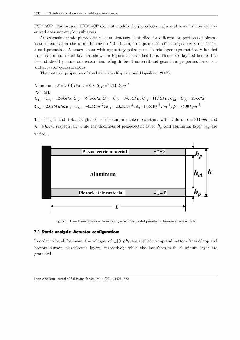
An extension mode piezoelectric beam structure is studied for different proportions of piezoe-lectric material in the total thickness of the beam, to capture the effect of geometry on the in-duced potential. A smart beam with oppositely poled piezoelectric layers symmetrically bonded to the aluminum host layer as shown in Figure 2, is studied here. This three layered bender has been studied by numerous researchers using different material and geometric properties for sensor and actuator configurations.
The material properties of the beam are (Kapuria and Hagedorn, 2007): Aluminum: E = 70.3GPa;ν = 0.345; ρ = 2710 kgm−3 PZT 5H:
C11 = C22 = 126GPa; C12 = 79.5GPa; C13 = C23 = 84.1GPa; C33 = 117GPa; C44 = C55 = 23GPa;
C66 = 23.25GPa; e31 = e32 = −6.5Cm−2 ; e33 = 23.3Cm−2 ; ∈3= 1.3×10⁻⁸ Fm−1; ρ = 7500kgm−3 The length and total height of the beam are taken constant with values 100L mm= and10h mm= , respectively while the thickness of piezoelectric layer ph and aluminum layer alh are
varied.
Figure 2 Three layered cantilever beam with symmetrically bonded piezoelectric layers in extension mode. 7.1 Static analysis: Actuator configuration:
In order to bend the beam, the voltages of 10volts± are applied to top and bottom faces of top and bottom surface piezoelectric layers, respectively while the interfaces with aluminum layer are grounded.
hp
hal
L
Aluminum
Piezoelectric material
hp
h
P
P Piezoelectric material

L. N. Sulbhewar et al./ Accuarate modelling of smart beams 1639
Latin American Journal of Solids and Structures 11 (2014) 1628-1650
Figure 3 Actuator configuration: Variation of tip deflection of three layered cantilever with thickness ratio.
The results obtained by present FSDT-CP and FSDT-LP of (Narayanan and Balamurugan, 2003) are compared for various thickness ratios
r = 2hp h( ) . The results for tip deflection of the
cantilever, plotted in Figure 3, show that FSDT-CP results closely match with ANSYS 2D simula-tion results for all regimes of thickness ratios. A refined mesh of 100x40 elements has been used for obtaining converged 2D analysis results. It is observed that FSDT-LP solutions deviate considera-bly from actual solutions when the piezoelectric material dominates the structure. It shows the inadequacy of FSDT-LP to take care of higher order through-thickness electric potential distribu-tion. In order to yield accurate results FSDT- LP demands sublayers in modelling of each piezoelec-tric layer. This obsevation is in consistent with findings of Rachmadini et al. (2005) which empha-size on the dicretization of the piezoelectric layer in the transverse direction to get accurate results.
Also, the variation of error (%) in tip deflection with thickness ratio, due to use of FSDT-LP with single layer modeling of piezoelectric layer is plotted in Figure 4.
Figure 4 Actuator configuration: Variation of error (%) in tip deflection of three layered cantilever smart beam with thickness ratio due
to use of FSDT-LP.

1640 L. N. Sulbhewar et al./ Accuarate modelling of smart beams
Latin American Journal of Solids and Structures 11 (2014) 1628-1650
Figure 5 Bimorph cantilever in actuator configuration.
Figure 4 shows that as we move from a beam of purely core material to piezoelectric material, the error (%) increases significantly being highest for bimorph (r=1). Hence, the bimorph configu-ration shown in Figure 5 is chosen for further detailed investigation.
Table 1 shows the results for the tip deflection of the bimorph configuration for different num-bers of sublayers in modeling with FSDT-LP. As seen from results, only sublayered model gives the accurate prediction of tip deflection as of FSDT-CP and ANSYS 2D results.
Table 1 Actuator configuration: Tip deflection of the bimorph cantilever ( h = 10mm; L = 100mm )
Formulation Tip deflection ( µm )
ANSYS 2D 0.790 FSDT CP 0.790 FSDT LP No sublayers 0.824 2 sublayers/layer 0.798 4 sublayers/layer 0.792
Figure 6 shows the comparison of transverse deflection results obtained with FSDT-CP, FSDT-
LP and ANSYS 2D simulation for the bimorph. For ANSYS 2D simulation a mesh size of 100x5 per layer is used to model the bimorph. FSDT CP results match closely with ANSYS 2D simulation while FSDT-LP results can only be improved by the addition of sublayers.
As shown in Figure 7, the through-thickness distribution of electric potential is nonlinear and
present FSDT-CP captures the accurate behaviour without any sublayers unlike FSDT-LP.
z
V=±10 volts
L
h P
x P
hp
hp

L. N. Sulbhewar et al./ Accuarate modelling of smart beams 1641
Latin American Journal of Solids and Structures 11 (2014) 1628-1650
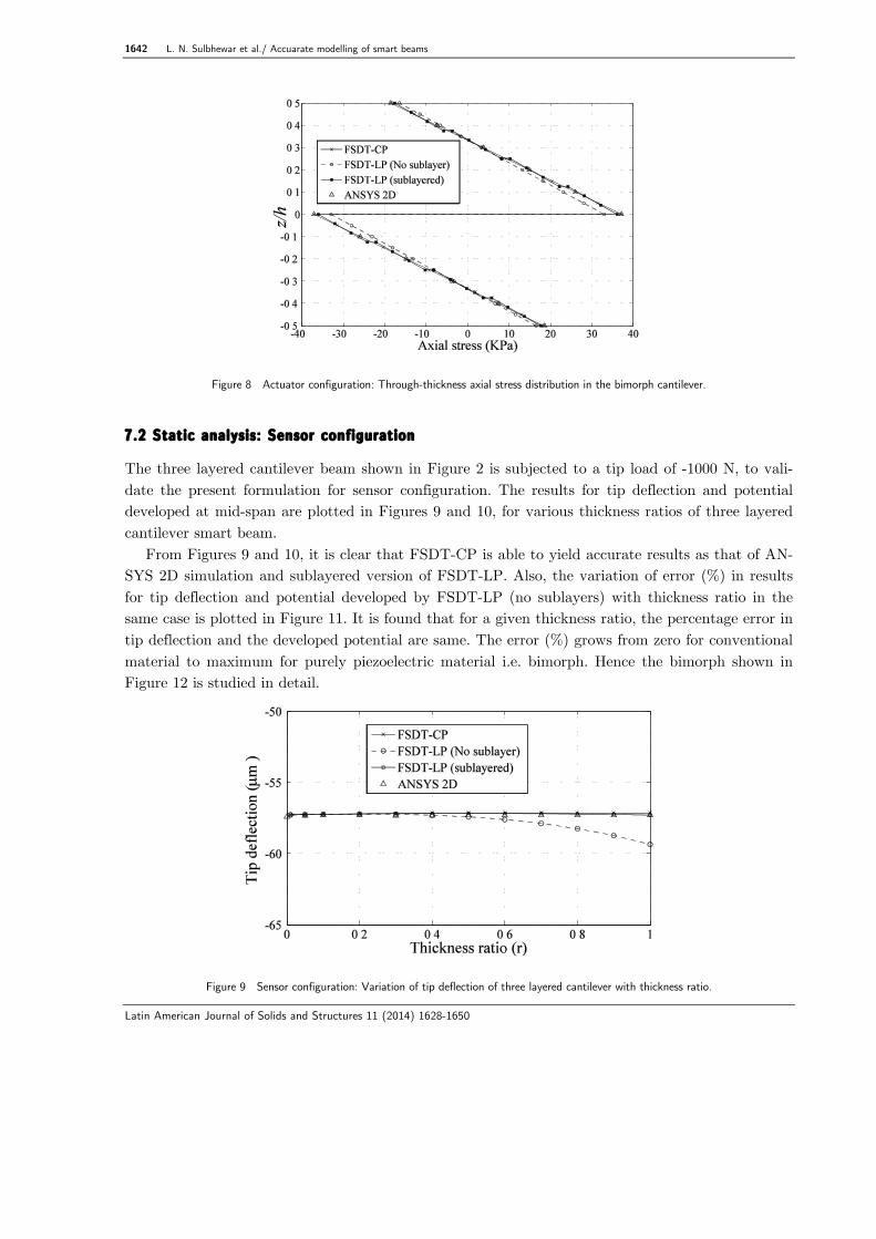
The axial stress developed in the bimorph cantilever is plotted in Figure 8, which is discontinuous and maximum at the interface. It is seen that FSDT-LP under predicts the maximum value and requires sublayers to reach the actual value as predicted by FSDT-CP and ANSYS 2D simulation.
Figure 6 Actuator configuration: Transverse deflection of the bimorph cantilever along the length.
Figure 7 Actuator configuration: Through-thickness potential distribution of the bimorph cantilever.
1642 L. N. Sulbhewar et al./ Accuarate modelling of smart beams
Latin American Journal of Solids and Structures 11 (2014) 1628-1650
Figure 8 Actuator configuration: Through-thickness axial stress distribution in the bimorph cantilever.
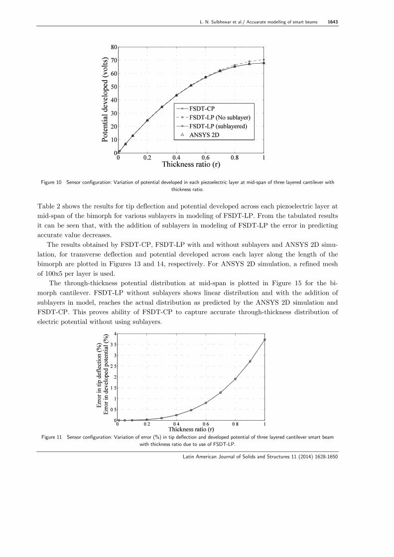
7.2 Static analysis: Sensor configuration
The three layered cantilever beam shown in Figure 2 is subjected to a tip load of -1000 N, to vali-date the present formulation for sensor configuration. The results for tip deflection and potential developed at mid-span are plotted in Figures 9 and 10, for various thickness ratios of three layered cantilever smart beam.
From Figures 9 and 10, it is clear that FSDT-CP is able to yield accurate results as that of AN-SYS 2D simulation and sublayered version of FSDT-LP. Also, the variation of error (%) in results for tip deflection and potential developed by FSDT-LP (no sublayers) with thickness ratio in the same case is plotted in Figure 11. It is found that for a given thickness ratio, the percentage error in tip deflection and the developed potential are same. The error (%) grows from zero for conventional material to maximum for purely piezoelectric material i.e. bimorph. Hence the bimorph shown in Figure 12 is studied in detail.
Figure 9 Sensor configuration: Variation of tip deflection of three layered cantilever with thickness ratio.
L. N. Sulbhewar et al./ Accuarate modelling of smart beams 1643
Latin American Journal of Solids and Structures 11 (2014) 1628-1650
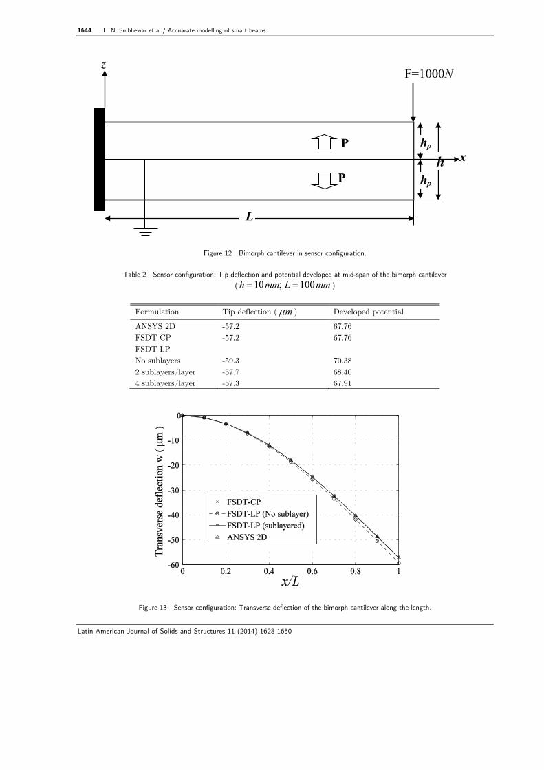
Figure 10 Sensor configuration: Variation of potential developed in each piezoelectric layer at mid-span of three layered cantilever with thickness ratio.
Table 2 shows the results for tip deflection and potential developed across each piezoelectric layer at mid-span of the bimorph for various sublayers in modeling of FSDT-LP. From the tabulated results it can be seen that, with the addition of sublayers in modeling of FSDT-LP the error in predicting accurate value decreases.
The results obtained by FSDT-CP, FSDT-LP with and without sublayers and ANSYS 2D simu-lation, for transverse deflection and potential developed across each layer along the length of the bimorph are plotted in Figures 13 and 14, respectively. For ANSYS 2D simulation, a refined mesh of 100x5 per layer is used.
The through-thickness potential distribution at mid-span is plotted in Figure 15 for the bi-morph cantilever. FSDT-LP without sublayers shows linear distribution and with the addition of sublayers in model, reaches the actual distribution as predicted by the ANSYS 2D simulation and FSDT-CP. This proves ability of FSDT-CP to capture accurate through-thickness distribution of electric potential without using sublayers.
Figure 11 Sensor configuration: Variation of error (%) in tip deflection and developed potential of three layered cantilever smart beam
with thickness ratio due to use of FSDT-LP.
1644 L. N. Sulbhewar et al./ Accuarate modelling of smart beams
Latin American Journal of Solids and Structures 11 (2014) 1628-1650
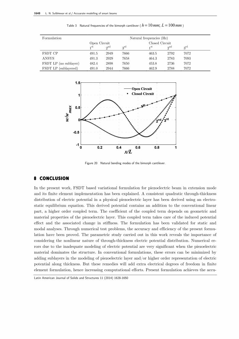
Figure 12 Bimorph cantilever in sensor configuration.
Table 2 Sensor configuration: Tip deflection and potential developed at mid-span of the bimorph cantilever ( h = 10mm; L = 100mm )
Formulation Tip deflection ( mµ ) Developed potential
ANSYS 2D -57.2 67.76 FSDT CP -57.2 67.76 FSDT LP No sublayers -59.3 70.38 2 sublayers/layer -57.7 68.40 4 sublayers/layer -57.3 67.91
Figure 13 Sensor configuration: Transverse deflection of the bimorph cantilever along the length.
z
L
h P
x
P
hp
hp
F=1000N

L. N. Sulbhewar et al./ Accuarate modelling of smart beams 1645
Latin American Journal of Solids and Structures 11 (2014) 1628-1650
Figure 14 Sensor configuration: Developed potential across each piezoelectric layer of the bimorph cantilever along the length.
The through-thickness axial stress distribution at the root of the bimorph has been plotted in Figure 16. As seen from the plot, FSDT-LP under predicts the maximum value developed at the top and bottom surfaces and shows discontinuity of the stress profile at the interface. These defi-ciencies are removed by sublayered model which approaches the actual distribution as predicted by FSDT-CP and ANSYS 2D simulation.
Figure 15 Sensor configuration: Through-thickness potential distribution at mid-span of the bimorph cantilever.

1646 L. N. Sulbhewar et al./ Accuarate modelling of smart beams
Latin American Journal of Solids and Structures 11 (2014) 1628-1650
Figure 16 Sensor configuration: Through-thickness axial stress distribution at the root of the bimorph cantilever.
7.3 Modal analysis
The FSDT-CP is validated here for its accuracy to predict the natural frequencies of piezoelectric extension mode smart beams. The numerical experiments are carried out for open and closed cir-cuit electrical boundary conditions. The three layered cantilever beam shown in Figure 2 is evaluat-ed here. For closed boundary condition, both top and bottom faces of each piezoelectric layer are grounded while for open circuit condition only interfaces with aluminum layer are grounded and the other faces are left free.
The variation of first natural frequencies with thickness ratio for the three layered cantilever beam in open and closed circuit electrical conditions are plotted in Figures 17 and 18, respectively. Present FSDT-CP gives accurate predictions of natural frequencies. The deterioration of accuracy of FSDT-LP (without sublayers) results with thickness ratio is evident from Figure 19.
Figure 17 Variation of first natural frequency of three layered cantilevered smart beam with thickness ratio in open circuit electrical boundary condition.

L. N. Sulbhewar et al./ Accuarate modelling of smart beams 1647
Latin American Journal of Solids and Structures 11 (2014) 1628-1650
Figure 18 Variation of first natural frequency of three layered cantilevered smart beam with thickness ratio in closed circuit electrical boundary condition.
As seen from Figure 19, the maximum error occurs when the beam is made up of purely piezoe-
lectric material i.e. bimorph. The first three natural frequencies for the bimorph cantilever in both electrical boundary conditions obtained by FSDT-CP, FSDT-LP with and without sublayers and ANSYS 2D simulation are tabulated in Table 3. As seen from the results, the FSDT-CP yields ac-curate natural frequencies without sublayers, unlike FSDT-LP. The first three natural bending modes for the bimorph are plotted in Figure 20.
Figure 19 Variation of error (%) in first natural frequency of three layered cantilever smart beam with thickness ratio due to use of FSDT
LP.
1648 L. N. Sulbhewar et al./ Accuarate modelling of smart beams
Latin American Journal of Solids and Structures 11 (2014) 1628-1650
Table 3 Natural frequencies of the bimorph cantilever ( h = 10mm; L = 100mm )
Formulation Natural frequencies (Hz) Open Circuit Closed Circuit 1st 2nd 3rd 1st 2nd 3rd FSDT CP 491.5 2949 7666 463.5 2792 7072 ANSYS 491.3 2929 7658 464.3 2783 7093 FSDT LP (no sublayer) 482.4 2898 7650 453.8 2736 7072 FSDT LP (sublayered) 491.0 2944 7666 462.9 2788 7072
Figure 20 Natural bending modes of the bimorph cantilever.
8 CONCLUSION
In the present work, FSDT based variational formulation for piezoelectric beam in extension mode and its finite element implementation has been explained. A consistent quadratic through-thickness distribution of electric potential in a physical piezoelectric layer has been derived using an electro-static equilibrium equation. This derived potential contains an addition to the conventional linear part, a higher order coupled term. The coefficient of the coupled term depends on geometric and material properties of the piezoelectric layer. This coupled term takes care of the induced potential effect and the associated change in stiffness. The formulation has been validated for static and modal analyses. Through numerical test problems, the accuracy and efficiency of the present formu-lation have been proved. The parametric study carried out in this work reveals the importance of considering the nonlinear nature of through-thickness electric potential distribution. Numerical er-rors due to the inadequate modeling of electric potential are very significant when the piezoelectric material dominates the structure. In conventional formulations, these errors can be minimized by adding sublayers in the modeling of piezoelectric layer and/or higher order representation of electric potential along thickness. But these remedies will add extra electrical degrees of freedom in finite element formulation, hence increasing computational efforts. Present formulation achieves the accu-
L. N. Sulbhewar et al./ Accuarate modelling of smart beams 1649
Latin American Journal of Solids and Structures 11 (2014) 1628-1650
racy of a 2D finite element without bringing in any additional degrees of freedom with the help of coupled field representation of electric potential. This novel work provides an efficient way to re-duce the 2D piezoelectric finite element to a truly 1D beam element, without sacrificing accuracy. References
Abramovich, H., Pletner, B. (1997). Actuation and sensing of piezolaminated sandwich type structures, Com-posite Structures 38: 17-27.
Abramovich, H. (1998). Deflection control of laminated composite beams with piezoceramic layers - closed form solutions, Composite Structures 43: 217-231.
Aldraihem, O.J., Khdeir, A.A. (2000). Smart beams with extension and thickness-shear piezoelectric actuators, Smart Materials and Structures 9: 1-9.
Bendary, I.M., Elshafei M.A., Riad, A.M. (2010) Finite Element Model of Smart Beams with Distributed Pie-zoelectric Actuators, J. Intelligent Material Systems and Structures 21:747-758.
Benjeddou, A., Trindade, M.A., Ohayon, R. (1997). A unified beam finite element model for extension and shear piezoelectric actuation mechanisms, J. Intelligent Material Systems and Structures 8: 1012-1025.
Benjeddou, A., Trindade, M.A., Ohayon, R. (2000). Piezoelectric actuation mechanisms for intelligent sand-wich structures, Smart Materials and Structures 9: 328-335.
Chee, C.Y.K., Tong, L., Steven, G.P. (1999). A mixed model for composite beams with piezoelectric actuators and sensors, Smart Materials and Structures 8: 417-432.
Crawley, E.F., de Luis, J. (1987). Use of piezoelectric actuators as elements of intelligent structures, AIAA J. 25: 1373-1385.
Donthireddy, P., Chandrashekhara, K. (1996). Modeling and shape control of composite beams with embedded piezoelectric actuators, Composite Structures 35: 237-244.
Elshafei, M.A., Alraiess, F. (2013). Modeling and analysis of smart piezoelectric beams using simple higher or-der shear deformation theory, Smart Materials and Structures 22: 35006-35019.
Hwang, W.S., Park, H.C. (1993). Finite element modeling of piezoelectric sensors and actuators, AIAA J. 31: 930-937.
Kapuria, S., Hagedorn, P. (2007). Unified efficient layerwise theory for smart beams with segmented exten-sion/shear mode, piezoelectric actuators and sensors, J. Mechanics of Materials and Structures 2: 1267-1298.
Khdeir, A.A., Aldraihem, O.J. (2001). Deflection analysis of beams with extension and shear piezoelectric pat-ches using discontinuity functions, Smart Materials and Structures 10: 212-220.
Narayanan, S., Balamurugan, V. (2003). Finite element modelling of piezolaminated smart structures for acti-ve vibration control with distributed sensors and actuators, J. Sound and Vibration 262: 529–562.
Neto, M.A., Yu, W., Roy, S. (2009). Two finite elements for general composite beams with piezoelectric actua-tors and sensors, Finite Elements in Analysis and Design 45: 295-304.
Peng, X.Q., Lam, K.Y., Liu G.R. (1998). Active vibration control of composite beams with piezoelectrics: A finite element model with third order theory, J. Sound and Vibration 209: 635-650.
Plagianakos, T.S., Saravanos, D.A. (2005). Coupled high-order shear layerwise analysis of adaptive sandwich piezoelectric composite beams, AIAA J. 43: 885-894.
Rachmadini, Y., Lee, S., Park H.C., Yoon, K.J., Goo, N.S. (2005). The effect of electro-mechanical coupling stiffness on the through-the-thickness electric potential distribution of piezoelectric actuators, Smart Materials and Structures 14: 754-758.

1650 L. N. Sulbhewar et al./ Accuarate modelling of smart beams
Latin American Journal of Solids and Structures 11 (2014) 1628-1650
Raja, S., Pratap, G., Sinha, P.K. (2002). Active vibration control of composite sandwich beams with piezoelec-tric extension-bending and shear actuators, Smart Materials and Structures 11: 63-71.
Robbins, D.H., Reddy, J.N. (1991). Analysis of piezoelectrically actuated beams using a layer-wise displace-ment theory, Computers and Structures 41: 265–279.
Rathi, V., Khan, A.H., (2012). Vibration attenuation and shape control of surface mounted, embedded smart beam, Latin American Journal of Solids and Structures 9: 401-424.
Saravanos, D.A., Heyliger, P.R. (1995). Coupled layerwise analysis of composite beams with embedded piezo-electric sensors and actuators, J. Intelligent Material Systems and Structures 6: 350-363.
Shen, M.H.H. (1995). A new modeling technique for piezoelectrically actuated beams, Computers and Structu-res 57: 361-366.
Sun, B., Huang, D. (2000). Analytical vibration suppression analysis of composite beams with piezoelectric la-minae, Smart Materials and Structures 9: 751-760.
Tzou, H.S., Tseng, C.I. (1988). Active vibration control of distributed parameter systems by finite element method, Computers in Engineering 3: 599-604.
Tzou, H.S., Tseng, C.I. (1991). Distributed vibration control and identification of coupled elastic/piezoelectric systems: finite element formulations and applications, Mechanical Systems and Signal Processing 5: 215-231.
Tzou, H.S., Ye, R. (1996). Analysis of piezoelastic structures with laminated piezoelectric triangle shell ele-ments, AIAA J. 34: 110-115.
Zhang, X.D., Sun, C.T. (1996). Formulation of an adaptive sandwich beam, Smart Materials and Structures 5: 814-823.


