
IIInnnpppuuuttt /// OOOuuutttpppuuuttt:::
AAA WWWhhhiiittteee PPPaaapppeeerrr
III///OOO TTTeeeccchhhnnnooolllooogggyyy SSSeeerrriiieeesss SSSyyysssttteeemmm zzz
jjjkkkeeettt tttnnneeerrr@@@uuusss... iiibbbmmm...cccooommm
NNNooovvveeemmmbbbeeerrr 222000000777

IIInnnpppuuuttt /// OOOuuutttpppuuuttt::: AAA WWWhhhiiittteee PPPaaapppeeerrr Much of the mainframe’s distinction leading to its success was founded on its I/O Architecture. The I/O model and its design implementation was an initial engineering idea which pioneered the unprecedented throughput this platform has today. An Abstract from the 1964 System/360 Architecture Announcement: An input/output system offering new degrees of concurrent operation, compatible channel operation, data rates approaching 5,000,000 characters/second, integrated design of hardware and software, a new low-cost, multiple-channel package sharing main-frame hardware, new provisions for device status information, and a standard channel interface between central processing unit and input/output devices. At the time an advanced concept was to ensure input/output (I/O) devices made systems specifically useful for given applications. A general method was needed for using I/0 devices differing in data rate, access, and function.
During this era, the new design was speculation, although from this point forward, IBM’s mainframe systems and its modern lineage succeeded beyond the imaginable dreams of the people who designed and built its introductory models. It changed the fortunes of our clients and of IBM, and to this day carries an extraordinary portion of the world’s workload. Most important, IBM continues to be motivated by the aspiration to make a difference in the world, and to shape global businesses with mainframe innovation. This paper attempts to briefly describe I/O anatomy and its implementation. Basics The terms “input” and “output” are used to describe the transfer of data between I/O devices and main storage. An operation involving this kind of transfer is referred to as an I/O operation. The facilities used to control I/O operations are collectively called the channel subsystem, (I/O devices and their control units attach to the channel subsystem.) The channel subsystem1 directs the flow of information between I/O devices and main storage. It relieves CPUs of the task of communicating directly with I/O devices and permits data processing to proceed concurrently with I/O processing. The channel subsystem uses one or more channel paths using a Channel Path ID (CHPID) as the communication link in managing the flow of information to or from I/O devices. 1. As part of I/O processing, the channel subsystem also performs a path-management operation by testing for channel-
path availability, chooses an available channel path, and initiates the performance of the I/O operation by the device.
At the time this photograph was taken at the System/360 announcement in Poughkeepsie on April 7 1964, the sage of what Fortune magazine writer T. A. Wise would later call IBM’s $5,000,000,000 gamble was well under way.
Tom Watson, Jr. at the System/360 press conference.

Illustration of I/O component relationship
Within the channel subsystem are subchannels. One subchannel is provided for and dedicated to each I/O device accessible to the program through the channel subsystem. Each subchannel provides information concerning the associated I/O device and its attachment to the channel subsystem. The subchannel also provides information concerning I/O operations and other functions involving the associated I/O device. The subchannel is the means by which the channel subsystem provides information about associated I/O devices to CPUs, which obtain this information by executing I/O instructions. The actual number of subchannels provided depends on the model and the configuration, although a system can support in the millions. I/O devices are attached through control units to the channel subsystem by means of channel paths. Control units may be attached to the channel subsystem by more than one channel path, and an I/O device may be attached to more than one control unit. In all, an individual I/O device may be accessible to the channel subsystem by as many as eight different channel paths via a subchannel, depending on the model and the configuration. The total number of channel paths provided by a channel subsystem depends on the model and the configuration. The current maximum is 0-255 (256). The performance of a channel subsystem depends on its use and on the system model in which it is implemented. Channel paths are provided with different data-transfer capabilities, and an I/O device designed to transfer data only at a specific rate (a magnetic-tape unit or a disk storage, for example) can operate only on a channel path that can accommodate at least this data rate. The channel subsystem contains common facilities for the control of I/O operations. When these facilities are provided in the form of separate, autonomous equipment designed specifically to control I/O devices, I/O operations are completely overlapped with the activity in CPUs. The only main-storage cycles required by the channel subsystem during I/O operations are those needed to transfer data and control information to or from the final locations in main storage, along with those cycles that may be required for the channel subsystem to access the subchannels when they are implemented as part of non-addressable main storage. These cycles do not delay CPU programs, except when both the CPU and the channel subsystem concurrently attempt to reference the same main-storage area.
Main MEMORY Tape
@@
==
Control Units Disk
Channel Path (CHPID)
* Channels are the communication path from the CSS to the control units and I/O devices * Channel Path Identifier (CHPID) is a value assigned to each channel path uniquely identifying that path * Control Units provide the logical capabilities to operate and control an I/O Device * Subchannels provide the logical appearance of a
device to the program and contains the information for sustaining an I/O
* Devices provides the external storage medium between the processing systems and its environment.
Subchannels
Printer
Channel Subsystem (CSS)
Channels
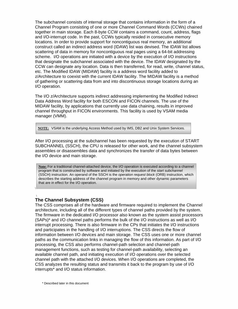
The subchannel consists of internal storage that contains information in the form of a Channel Program consisting of one or more Channel Command Words (CCWs) chained together in main storage. Each 8-byte CCW contains a command, count, address, flags and I/O-interrupt code. In the past, CCWs typically resided in consecutive memory locations. In order to provide support for noncontiguous real memory, an additional construct called an indirect address word (IDAW) list was devised. The IDAW list allows scattering of data in memory for noncontiguous real pages using a 64-bit addressing scheme. I/O operations are initiated with a device by the execution of I/O instructions that designate the subchannel associated with the device. The IDAW designated by the CCW can designate any location. Data is then transferred, for read, write, channel status, etc. The Modified IDAW (MIDAW) facility is a address word facility added to z/Architecture to coexist with the current IDAW facility. The MIDAW facility is a method of gathering or scattering data from and into discontinuous storage locations during an I/O operation. The I/O z/Architecture supports indirect addressing implementing the Modified Indirect Data Address Word facility for both ESCON and FICON channels. The use of the MIDAW facility, by applications that currently use data chaining, results in improved channel throughput in FICON environments. This facility is used by VSAM media manager (VMM).
After I/O processing at the subchannel has been requested by the execution of START SUBCHANNEL (SSCH), the CPU is released for other work, and the channel subsystem assembles or disassembles data and synchronizes the transfer of data bytes between the I/O device and main storage.
\ \
The Channel Subsystem (CSS) The CSS comprises all of the hardware and firmware required to implement the Channel architecture, including all of the different types of channel paths provided by the system. The firmware in the dedicated I/O processor also known as the system assist processors (SAPs)* and I/O channel paths performs the bulk of the I/O instructions as well as I/O interrupt processing. There is also firmware in the CPs that initiates the I/O instructions and participates in the handling of I/O interruptions. The CSS directs the flow of information between I/O devices and main storage. The CSS uses one or more channel paths as the communication links in managing the flow of this information. As part of I/O processing, the CSS also performs channel-path selection and channel-path management functions, such as testing for channel-path availability, selecting an available channel path, and initiating execution of I/O operations over the selected channel path with the attached I/O devices. When I/O operations are completed, the CSS analyzes the resulting status and transmits it back to the program by use of I/O interrupts* and I/O status information.
* Described later in this document
Note: For a traditional channel-attached device, the I/O operation is executed according to a channel program that is constructed by software and initiated by the execution of the start subchannel (SSCH) instruction. An operand of the SSCH is the operation request block (ORB) instruction, which describes the starting address of the channel program in memory and other dynamic parameters that are in effect for the I/O operation.
NOTE: VSAM is the underlying Access Method used by IMS, DB2 and Unix System Services.
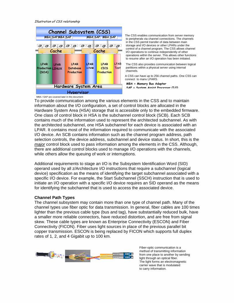
Illustration of CSS relationship
MBA / SAP are covered later in this document
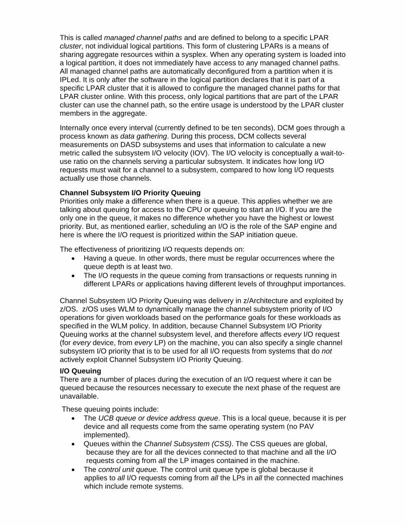
To provide communication among the various elements in the CSS and to maintain information about the I/O configuration, a set of control blocks are allocated in the Hardware System Area (HSA) storage that is accessible only to the embedded firmware. One class of control block in HSA is the subchannel control block (SCB). Each SCB contains much of the information used to represent the architected subchannel. As with the architected subchannel, one HSA subchannel for each device is associated with an LPAR. It contains most of the information required to communicate with the associated I/O device. An SCB contains information such as the channel program address, path selection controls, the device address, subchannel and device status. In short, this is the major control block used to pass information among the elements in the CSS. Although, there are additional control blocks used to manage I/O operations with the channels, while others allow the queuing of work or interruptions. Additional requirements to stage an I/O is the Subsystem Identification Word (SID) operand used by all z/Architecture I/O instructions that require a subchannel (logical device) specification as the means of identifying the target subchannel associated with a specific I/O device. For example, the Start Subchannel (SSCH) instruction that is used to initiate an I/O operation with a specific I/O device requires an SID operand as the means for identifying the subchannel that is used to access the associated device. Channel Path Types The channel subsystem may contain more than one type of channel path. Many of the channel types use fiber optic for data transmission. In general, fiber cables are 100 times lighter than the previous cable type (bus and tag), have substantially reduced bulk, have a smaller more reliable connectors, have reduced distortion, and are free from signal skew. These cable types are known as Enterprise Connectivity (ESCON) and Fiber Connectivity (FICON). Fiber uses light sources in place of the previous parallel bit copper transmission. ESCON is being replaced by FICON which supports full duplex rates of 1, 2, and 4 Gigabit up to 100 km.
Fiber-optic communication is a method of transmitting information from one place to another by sendinglight through an optical fiber. The light forms an electromagnetic carrier wave that is modulated to carry information.
Channel Subsystem (CSS)
LPAR Production
(SOA)
LPAR LINUX
LPAR Database Production
LPAR z/VM
LPAR CICS
Production
LPARTest
The CSS enables communication from server memory to peripherals via channel connections. The channels in the CSS permit transfer of data between main storage and I/O devices or other LPARs under the control of a channel program. The CSS allows channel I/O operations to continue independently of other operations within the server. This allows other functions to resume after an I/O operation has been initiated. The CSS also provides communication between logical partitions within a physical server using internal channels.
A CSS can have up to 256 channel paths. One CSS can connect to many LPARS.
Cache
MBA SAP
CP CP CP CP CP CP CP CP CP CP CP CP
MBA SAP MBA SAP MBA SAP
Cache
MBA = Memory Bus Adapter SAP = System Assist Processor (I/OHardware System Area
((HSA)Hypervisor

Here are a few distinguishing features between these two channel types:
* FICON improves distance solutions by a factor of 10 * FICON provides up to twenty times greater bandwidth per channel * FICON supports 16 times as many devices
* FICON uses fiber more efficiently * FICON provides greater configuration flexibility * FICON provides relief for “channel constrained” systems
i.e. FICON delivers up to 2688 ESCON equivalent channels on an z9 EC, with the maximum number of 336 FICON channels (448MHz).
Another channel type is the IBM Open Systems Adapter (OSA) which is an integrated hardware feature that allows the Z platform to provide industry-standard connectivity directly to clients on local area networks (LANs) and wide area networks (WANs). With OSA, Z is an open systems platform that brings mainframe resources directly to its attached networks.
Other channels types are hipersockets which allows a seamless network connection between LPAR images within a single machine and coupling facility links used for connecting systems providing resource and data sharing functionality.
Sharing Channels Channels can be shared within a CSS via the Multiple Image Facility (MIF) and across CSSs using Spanned Channels. I/O sharing was already possible in a pre-MIF ESCON environment, where multiple systems could share control units, devices, and common links through ESCON device features. Under this situation, channel assignment to an LPAR, however was more ‘static’. Channels could only be defined as reconfigurable, enabling them to be administratively removed from one logical partition (LPAR) and attached to another. They were dedicated to one logical partition at a particular time and could not be shared by other logical partitions. With MIF, the server’s channel subsystem provides channel path sharing by extending the logical access capability of the channel architecture to logical partitions.
MIF provides the same communication between logical partitions and I/O devices, but using fewer physical channels, and therefore, fewer ports and possible control unit link interfaces. Also, manual reassignment of channels between logical partitions to handle different workloads is no longer necessary, which improves reliability, availability and less costly not needing to acquire additional channel cards.
Control Unit
LPAR 1 LPAR 2 LPAR 3
ControlUnit
LPAR 1 LPAR 2 LPAR 3
M I F
With MIF, the channel subsystem provides channel path sharing by extending the logical access capability of the ESCON / FICON architecture to logical partitions.
Pre-MIF

Using MIF, each LPAR has its own view of a shared channel (logical channel path image) and each control unit connected to the shared channel (subsystem image).
The allocation of additional channels when adding new logical partitions or for availability reasons is no longer required, and elimination of under utilized channels is possible. MIF eases system and configuration management tasks such as enabling disaster backup solutions, consolidating applications, and providing migration, test, and other special environments. Moreover, MIF improves system configuration flexibility, especially in handling greater numbers of logical partitions, through easier access to control units and reduced operational complexity. Channel Subsystem Images Before we describe Spanned Channels, let’s discuss multiple channel subsystems. The mainframe can support more than one Channel Subsystem. The multiple-channel-subsystem (MCSS) architecture was introduced with the z990 family and its intentions were to design, and support efforts focused on expanding upon the z platform existing multiple-image facility (MIF) in order to:
1) Minimize the changes necessary to provide greater I/O capacity, 2) Build upon and increase the MIF channel-sharing capabilities, 3) Ensure backward compatibility with previous mainframe computing environments. Each Logical CSS (LCSS) may have from 1 to 256 channels and may in turn be configured with 1 to 15 logical partitions (LPARs). At the time of this writing up to four LCSS were available on an Enterprise Class machine (On a Business Class depending on the model up to two). The LCSS uses virtualization in order to share channel between the CSS’.
In order to achieve the necessary increase in the total I/O capacity, several z/Architecture constraints had to be addressed and redefined in a manner that minimizes their impact on providing more than 256 channels and associated I/O devices on the z platform operating systems.
Specifically, the architecturally defined channel-path identification number (mentioned earlier) known as the channel-path identifier (CHPID), had to be maintained without change. The CHPID value is defined as an 8-bit binary number resulting in a range of unique CHPID values from 0 to 255, therefore, a maximum of 256 channel paths were possible on previous S/370, S/390, and early z/Architecture-class systems. Since the inception pioneering of the S/370 XA channel-subsystem architecture in the late 1970s, this 8-bit CHPID has been maintained without change because of its pervasive use in the z/OS and z/VM operating systems. For example, the CHPID value is maintained in many internal programming control blocks, is displayed in various operator messages, and is the object of various system commands, programming interfaces, etc., all of which would have to be redesigned if the CHPID value was increased to more than an 8-bit number in order to accommodate more than 256 channel paths.
Note: Under the present z/Architecture the mainframe theoretically can support up to 256 CSS’.
Note: It is still possible to define dedicated channels.

To accommodate more than 256 channel paths an additional level of channel-addressing indirection was created that allows more than 256 physical channel paths to be installed and uniquely identified without changing the legacy 8-bit CHPID value and the corresponding programming dependencies on the CHPID. This new channel-path-identification value, called the physical-channel identifier (PCHID), is a 16-bit binary number ranging from 0 to 65,279, which uniquely identifies each physically installed channel path. With the current mainframe platform, a maximum of 1024 external channel paths (i.e., ESCON, FICON, OSA) and 48 internal channel paths (e.g., Internal Coupling and IQDIO hiperlinks) are each assigned a unique PCHID. The PCHID value is transparent to the programs operating in each LPAR. Correspondingly, both of these I/O configuration management programs are enhanced to provide the controls necessary to associate the PCHID value of each channel path with its corresponding CHPID values. Therefore, a PCHIP reflects the physical location of a channel type interface based on the I/O cage location, slot number and port number.
CHPIDs are not pre-assigned on mainframe servers. It is the user responsibility to assign the CHPID numbers through the use of the CHPID Mapping Tool (CMT) or directly with the Hardware Configuration Definition (HCD)2. Assigning CHPIDs means that the CHPID number is associated with a physical channel port location (PCHID) and a LCSS. The CHPID number range is still from ‘00’ to ‘FF’ and must be unique within an LCSS. Having said this, the same CHIPD number can be used by multiple LCSS’.
The Physical Channel Identifier (PCHID) Summary Report lists the PCHIDs defined in the Input Output Configuration Data Set (IOCDS) as well as the channel paths that cannot have PCHIDs. The IOCDS is loaded into the Hardware System Area described earlier. The IOCDS is output from an Input Output Definition File (IODF)3. The device configuration is loaded at Power On Reset (POR) when the machine is turned on.
2. HCD is a special TSO/ISPF application used to configure mainframe hardware 3. The I/O definition file (IODF) is a VSAM linear data set that is built and maintained by HCD.
Up to28 I/O Feature Slots
An I/O Cage in the mainframe houses different types of
channels in the form of circuit cards
I/O cards
OSA ESCON FICON FICON OSA
I/O SLOT 1 2 3 4 5 … … … …
110 111 112
120
122
123 124
125 126
127
121
Illustration
140 150
141 151
160 161 162
I/O PORTS
PCHIDs

For each channel path, the report shows the following:
* PCHID number associated with the channel path * CHPID number of the channel path * Channel path type * Control Unit number associated with the channel path * CSS IDs to which the channel path has access * Any configuration discrepancy or comment for the channel path.
Sample PCHID Report
Each logical CSS is called a channel-subsystem image, and each image is identified by a unique 8-bit binary number ranging from 0 to 254, called the channel-subsystem-image identifier (CSSID), resulting in an architecture maximum of 256 channel subsystem images per central processor complex (CPC) footprint. Additionally, each CSS image may be configured with a maximum of 256 unique channel paths, called a channel-path set (CPS). This results in an architecture maximum of 64K physical channel paths for a given CPC footprint.
z/OS LINUX Database
LPAR Hipervisor
LPAR 1
LPAR 2
LPAR 3
H S A
Physically machine
attached hardware
configuration device
LAN attached hardware
configuration devices
Describes the configuration for several LPAR’s Hardware
The Input Output Configuration Program used to compile an I/O environment
Feature Code(Channel Type)

Each channel-subsystem image is also structured to provide its own z/Architecture MIF. In this case, each MIF is identified by a value or number known as an Image ID (IID) providing the replication of both channel-path and subchannel controls. This allows each of the logical partitions that are configured to a given channel subsystem image to have its own set of I/O controls in order to dynamically access and share up to 256 physical channel paths and up to 64K physical I/O devices. The physical devices are mapped to logical device structures defined in a Multiple Subchannel Set (MSS). MSS will be discussed shortly. illustration
Spanned channels Channel paths are called “spanned” channel paths when they allow the channel paths and their attached I/O devices to be dynamically and transparently shared by programs operating in LPARs which are configured to different channel-subsystem images, that is, they span multiple channel-subsystem images. Correspondingly, each configured LPAR is assigned to an appropriately defined CSS image in order to accommodate the I/O connectivity requirements of the operating system and associated application programs that are executed in each of the configured LPARs. Illustration of Spanned Channels
LPAR 1
LPAR 2 LPAR 3 LPAR 4 H S A
z/OS LINUX Database z/VM
LPAR Hipervisor
IID 3 within
CSSID 4
IID 6 within
CSSID 1
IDD 3 within
CSSID 1 IID14 within
CSSID3 IID=3
IID=6CSSID 1
IID=3 CSSID 4
IID=14 CSSID 3
CSSID 254IID=254
ChannelSubsystem
***
MCSS
Partition 1
Partition 2
Partition14
Partition16
Partition17
Partition15
CSS
MIF-1 MIF-2 MIF-F
. . .
Partition18
Partition 60
CSS
MIF-1 MIF-2 MIF-F . . . MIF-3

In summary, each configured mainframe LPAR is assigned to an appropriately defined CSS image in order to accommodate the I/O connectivity requirements of the operating system and associated application programs that are executed in each of the configured LPARs. The MIF provides for intra-CSS LPAR channel sharing and the Spanned Channels provide for inter-CSS LPAR channel sharing. Parallel Access Volumes Before we describe Multiple Channel Sets (MSS) we’ll define functionality within the Enterprise Storage Subsystem called Parallel Access Volumes (PAV). This feature is incorporated into defining MSS. In the past, due to device circuitry and storage architecture, any single device located amongst the DASD farm used one hardware address. Therefore, only one I/O request at a time could access data on that disk. The other I/O requests targeted for that device were queued waiting for their turn. This had very severe performance impact which could easily back up in to the overall mainframe workload. In other words, before PAV was available, the operating system allowed only one request at a time for each volume identified within the IOCDS containing a hardware address. Thus, when there was an active I/O to a disk volume, its hardware address was flagged “busy”. Introducing Parallel Access Volumes, in place of one hardware address there are multiple addresses associated with the same logical volume and each such address is associated with a corresponding subchannel known as a PAV Alias. Thus, a PAV disk is represented by a base address and possibly one or more aliases. Because the mainframe I/O architecture permits a unit address and its associated subchannel within a Channel Subsystem to handle only a single request at a time, PAV supports multiple concurrent I/O requests from the same system against the same logical volume. Using this technology virtually eliminates I/O queuing to a device allowing multiple requests breaking the serialization to a volume. Greater throughput is achieved transparent to the executing applications.
The PAV Aliases can also be workload managed. As hhhooottt I/O begins to occur on a different disk device the aliases can be dynamically migrated to that disk ensuring applications meet their service level objectives. This is performed through a policy or rule based management by system administrators. There can be a mixture of both static and dynamic PAV devices depending on business needs.
I/O
I/O
I/O
Applications
1
2
3
4
IO Queue
IO QueueApplications
1
2
3
4
with Alias’

Multiple Subchannel Sets The multiple subchannel sets (MSS) functionality was introduced with the System z9 and should not be confused with multiple channel subsystems (MCSS). In most cases a subchannel represents an addressable device. For example, a disk control unit with 40 drives uses 40 subchannels. An addressable device is associated with a specific device number. Subchannel numbers (including their implied path information to a device) are limited to four hexadecimal digits by hardware and software architectures. Four hexadecimal digits provide 64 K addresses, known as a set. IBM reserved 256 subchannels for system use, leaving 63.75 K subchannels for general use with the current mainframe implementation. The Parallel Access Volume (PAV) feature has made this limitation of subchannels a problem for larger installations. A single disk drive (with PAV) often consumes at least four subchannels. Because the use of four hexadecimal digits for subchannels (and device numbers corresponding to subchannels) is architected in a number of places, it was difficult to remove this constraint. Simply expanding the field would break too many system programs. A solution was devised and allowed sets of subchannels (“addresses”) incorporating a current implementation of two sets. Each set provides 64 K addresses. Subchannel set 0, the first set, still reserves subchannels for IBM use although the number of reserved subchannels (256) on the System z9 is less than earlier servers (1024). Subchannel set 1 provides a full range of 64 K subchannels on a System z9. In principle, subchannels in either set could be used for any device addressing purpose. However, the current implementation (in z/OS) restricts subchannel set 1 to disk alias subchannels. Subchannel set 0 may be used for base addresses and for alias addresses.
The System Assist Processor (SAP) The mainframe uses an asynchronous processor called the System Assist Processor (SAP) which is architected into the I/O design dedicated to drive the mainframe’s channel subsystem(s). This is an I/O Processor (IOP) running special Licensed Internal Code (LIC) and takes responsibility during the execution of an I/O operation. The SAP relieves the OS (and consequently, general CP involvement) during the setup of an I/O operation. It does the scheduling of an I/O, that is, it finds an available channel path to the device and guarantees that the I/O operation starts. SAP, however, is not in charge of the movement between main storage and the channel.
Mainframe Logical Channel Subsystem
Subchannls
Subchannel Set 0
Subchannel Set 1
63.75K 64K devices devices
SET 0 SET 1

A SAP processes the Start-Subchannel (SSCH) instruction and locates a subchannel or logical device in its work queue. The requests in this queue are processed based upon the I/O Priority assigned either by the Workload Manager policy or by the hardware, then tries to locate an available channel that succeeds in connecting to a control unit, then starts the I/O operation. The SAP uses information in the subchannel to determine which channels and control units can be used to reach the target device. The SAP serves a very critical role in the mainframe’s ability to executing thousands of I/Os at any moment in time executing up to 100,000 I/Os per second. Each model mainframe comes with a default number of SAP engines, although more SAPs can be added through special licensing.
Memory Bus Adapter A Memory Bus Adapter (MBA) is a card designed to provide the path for data between memory and the I/O channels using Self-Timed Interconnect (STI) cables. An MBA uses an STI to gather and send data. The MBA card is hot-pluggable. Up to 32 MBA cards are available for a high-end machine.
The self-timed interface (STI) was first introduced with the third generation of S/390 CMOS servers (G3) and devised to satisfy the increasing I/O bandwidth requirements. As the performance of the processors increased, it became apparent that in order for IBM to be successful with its line of early CMOS servers, bandwidth and connectivity of the I/O subsystem had to scale along with the processor. STI was developed to satisfy those requirements.
Each STI has a bidirectional bandwidth of 2.7 GBps for I/O and 2.0 GBps for ICB-4s and STI-3 extender cards. When populated with 16 STIs, each book containing the CPUs Multi Chip Module (MCM) has a maximum bandwidth of 43.2 GBps.
I/O Interrupts I/O interruptions provide a means for the CPU to change its state in response to conditions that occur at I/O devices or subchannels. These conditions can be caused by the program, by the channel subsystem, or by an external event at the device. When an I/O operation is requested by a program executing a task to the channel subsystem, it calls the input/output supervisor (IOS) through a system Supervisor Call (SVC 0) instruction, the SVC then passes control to IOS. In z/Architecture, the I/O operation is not handled by the CP executing z/OS code, but by the SAP engine mentioned earlier.
When an I/O operation or sequence of I/O operations are initiated, the channel subsystem and the device generate status conditions. The generation of these conditions can be brought to the attention of the program by means of an I/O interruption. The status conditions, as well as an address and a count indicating the extent of the operation sequence are presented to the program in the form of a subchannel-status word (SCSW) parameter. The SCSW is stored in an interruption-response block (IRB) during the execution of TEST SUBCHANNEL to see whether the channel is clear of the I/O operation.
Book Card Layout Fan out from memory to I/O Adapters
MBA MBA
MBA MBA MBA MBA MBA MBA
MBA

Normally an I/O operation is performed until the device signals primary interruption status. Primary interruption status can be signaled during initiation of an I/O operation. Now, how does Channel Subsystem and the CP become aware that the I/O operation handled by the channel is finished? This is handled through an I/O interrupt triggered by the channel. See I/O scenario later in this document. Dynamic Channel path Management In the past, LPAR to channel mapping was static and required a reconfiguration of the LPAR in order to adjust resources to changing workload. This was unwieldy since workloads change during the day and channel utilization at any point was either under or over utilized. Overall, this affected the entire operation of the machine burdening hardware cost with equipment not used or applications experiencing decreased throughput. This also required skill personnel to analyze reports to attempt some form of resource balancing adequate enough to achieve daily service levels. During month end or year end processing further analysis and reconfiguration needed to be assessed. In these instances where application’s workload spiked additional channel cards were likely purchased to meet the infrequent demands and in the absence of high demand, channels went unused. Dynamic channel path management (DCM) allows Channels to dynamically change channel path definitions to attached DASD control units in response to changing workloads, moving channel resources to the control units as required. When combined with WLM and hardware components, DCM moves the channel resources to control units that are being used by business-critical workloads to help them meet their service level objectives. This also enhances availability as well as maximizing overall hardware usage. This Intelligent Resource Director feature also complements PAV when moving dynamic aliases to high utilized devices as workload changes. Illustration – when workload increases greater bandwidth is obtained using DCM
During system initialization, DCM builds tables that represent the physical I/O topology. These tables include entries for each channel, ESCON or FICON director, and DASD control unit that is physically attached to and accessible by this system. The topology tables are used by DCM to determine what potential paths exist that DCM could add to a control unit in order to help it achieve its bandwidth requirements.
mainframe
@ @
LPAR LPAR LPAR LPARSOA LINUX DB OLTP
DCM Cluster mainframe
@ @
LPAR LPAR LPAR LPAR SOA LINUX DB OLTP
DCM Cluster
Channels
Control Control Units Unit Channels
move dynamically
Disks Disks
This is called managed channel paths and are defined to belong to a specific LPAR cluster, not individual logical partitions. This form of clustering LPARs is a means of sharing aggregate resources within a sysplex. When any operating system is loaded into a logical partition, it does not immediately have access to any managed channel paths. All managed channel paths are automatically deconfigured from a partition when it is IPLed. It is only after the software in the logical partition declares that it is part of a specific LPAR cluster that it is allowed to configure the managed channel paths for that LPAR cluster online. With this process, only logical partitions that are part of the LPAR cluster can use the channel path, so the entire usage is understood by the LPAR cluster members in the aggregate. Internally once every interval (currently defined to be ten seconds), DCM goes through a process known as data gathering. During this process, DCM collects several measurements on DASD subsystems and uses that information to calculate a new metric called the subsystem I/O velocity (IOV). The I/O velocity is conceptually a wait-to-use ratio on the channels serving a particular subsystem. It indicates how long I/O requests must wait for a channel to a subsystem, compared to how long I/O requests actually use those channels. Channel Subsystem I/O Priority Queuing Priorities only make a difference when there is a queue. This applies whether we are talking about queuing for access to the CPU or queuing to start an I/O. If you are the only one in the queue, it makes no difference whether you have the highest or lowest priority. But, as mentioned earlier, scheduling an I/O is the role of the SAP engine and here is where the I/O request is prioritized within the SAP initiation queue. The effectiveness of prioritizing I/O requests depends on:
• Having a queue. In other words, there must be regular occurrences where the queue depth is at least two.
• The I/O requests in the queue coming from transactions or requests running in different LPARs or applications having different levels of throughput importances.
Channel Subsystem I/O Priority Queuing was delivery in z/Architecture and exploited by z/OS. z/OS uses WLM to dynamically manage the channel subsystem priority of I/O operations for given workloads based on the performance goals for these workloads as specified in the WLM policy. In addition, because Channel Subsystem I/O Priority Queuing works at the channel subsystem level, and therefore affects every I/O request (for every device, from every LP) on the machine, you can also specify a single channel subsystem I/O priority that is to be used for all I/O requests from systems that do not actively exploit Channel Subsystem I/O Priority Queuing.
I/O Queuing There are a number of places during the execution of an I/O request where it can be queued because the resources necessary to execute the next phase of the request are unavailable.
These queuing points include: • The UCB queue or device address queue. This is a local queue, because it is per
device and all requests come from the same operating system (no PAV implemented).
• Queues within the Channel Subsystem (CSS). The CSS queues are global, because they are for all the devices connected to that machine and all the I/O requests coming from all the LP images contained in the machine.
• The control unit queue. The control unit queue type is global because it applies to all I/O requests coming from all the LPs in all the connected machines which include remote systems.

In summary, features described as designed within the mainframe’s architecture solve problems where I/O delays can affect a business’ ability to meet customer demand reflecting directly to the organization’s bottom line revenue. From the introduction of the System/360’s multiplex channels to today’s multiple channel subsystems and channel management capability, IBM continues to be inspired by the objective to make a difference in the world shaping global businesses with mainframe innovation. An I/O scenario
1. The user program begins an I/O operation by issuing an OPEN instruction and requesting either input or output of data using an I/O instruction like GET, PUT, READ, or WRITE, and specifying a target I/O device. An I/O macro instruction invokes an access method that interprets the I/O request and determines which system resources are needed to satisfy the request. NOTE:
The user program could bypass the access method, but it would then need to consider many details of the I/O operation, such as the physical characteristics of the device. The program would also have to create a channel program composed of instructions for the channel subsystem, and invoke the EXCP processor, an IOS driver, to handle the next phase of the I/O process. By using an access method, a user program maintains device independence.
2. There are several MVS access methods, each of which offers different functions to the user program. The selection of an access method depends on how the program plans to access the data (randomly, or sequentially, for example) and the data set organization (sequential, PDS, VSAM, and so on). 3. To request the movement of data, either the access method or the user program presents information about the operation to the EXCP processor by issuing the EXCP macro instruction. EXCP translates the information (CCW Command Chain Addresses and CCW Data Addresses) into a format acceptable to the channel subsystem, fixes the pages containing the CCWs and the data buffers, validity-checks the extents, and invokes the I/O Supervisor (IOS) within the Channel Subsystem (CSS). 4. IOS places the request for I/O on the SAP queue for the chosen I/O device in the UCB (this is the unit control block and represents the device address) and issues the Start Subchannel (SSCH) instruction to send the request to the channel subsystem. At this point, the central processor can continue with other work until the channel subsystem indicates, with an I/O interrupt, that the I/O operation has completed. 5. The channel subsystem selects a channel path to initiate the I/O operation between the channel and control unit or device, and this controls the movement of data between the channel and processor storage.
User Appl
Program
Access Method
I/ODrivers
SAP Channels Control Unit
Device
General CP Channel Subsystem
Writes and-or Reads
Depends on File organization
(PDS, VSAM, QSAM)
Initiates an Execute ChannelProgram (EXCP)
Hand-offCCW
Created
I/O placedon queue(SSCH)
CHPID selected Controller verifies device availability and connects to the device
Data access1 2 3 4 5 6 7
Data is placed in output buffer
Controller disconnects from device
UCB
CSS signalsI/O Interruptcompletion
14 13 12 11 10 9 8 Verifies I/O status
EXCP posts back to Access
Method
Dispatcher is notified from Access Method
User pgm receives data and redispatched

6. A control unit or fiber director is selected from the I/O Configuration Dataset (IOCDS) that can access the device(s) where the requested data resides. 7. The connection to the device last as long as necessary for the device’s positional sensor to reach the track (disk area) where the data is located. 8. The data is placed in an available buffer from the controller’s buffer pool and compiled into the appropriate frames (data grams) in order to be transfer back to the channel subsystem. 9. Once the data is transfer back to the controller, it disconnects for the next I/O freeing its buffer and returning it to the pool. 10. When the I/O operation is complete, the channel subsystem signals completion by generating an I/O interrupt which is handled by a special system routine called the First Level Interrupt Handler (FLIH). There are six different types of interrupts within z/OS where I/O is one of them. 11. SAP processes the interruption by determining the status of the I/O operation (successful or otherwise) from the channel subsystem using a Test Subchannel (TSCH) instruction. 12. EXCP indicates that I/O is complete by posting status to the access method and calling the z/OS task dispatcher. 13. When appropriate, the dispatcher reactivates the access method. 14. The access method returns control to the user program for redispatch by the z task dispatcher to continue its processing restoring the Program Status Word (PSW) of the next executable instruction within the application module that issued the I/O. - - - - -


