Leonardo
A Visual Aid for Artists and Others with Retinitis Pigmentosa ('Tunnel Vision')Author(s): Ian E. Gordon and Ewart JohnsSource: Leonardo, Vol. 17, No. 3 (1984), pp. 202-204Published by: The MIT PressStable URL: http://www.jstor.org/stable/1575192 .
Accessed: 12/06/2014 22:47
Your use of the JSTOR archive indicates your acceptance of the Terms & Conditions of Use, available at .http://www.jstor.org/page/info/about/policies/terms.jsp
.JSTOR is a not-for-profit service that helps scholars, researchers, and students discover, use, and build upon a wide range ofcontent in a trusted digital archive. We use information technology and tools to increase productivity and facilitate new formsof scholarship. For more information about JSTOR, please contact [email protected].
.
The MIT Press and Leonardo are collaborating with JSTOR to digitize, preserve and extend access toLeonardo.
http://www.jstor.org
This content downloaded from 91.229.248.152 on Thu, 12 Jun 2014 22:47:27 PMAll use subject to JSTOR Terms and Conditions
A Visual Aid for Artists and Others with
Retinitis Pigmentosa ('Tunnel Vision')
Ian E. Gordon and Ewart Johns
Abstract-Tunnel vision resulting from retinitis pigmentosa is a severe handicap for artists, designers and draughtsmen. Composition and the interpretation of depicted material is difficult because only a portion of the material is visible at a time. Collaboration between an experimental psychologist and a practising artist afflicted with tunnel vision has produced two useful ways of effectively reducing the size of visual material, permitting more of it to be seen at a glance. One method uses a video camera and monitor; the other, a less expensive and optically superior method, uses two plane mirrors.
Retinitis pigmentosa is the name given to a group of hereditary diseases of the eye. The diseases vary in patterns of symp- toms, but all lead to a gradual and irreversible collapse of the visual field. In a common form, a region of blindness develops in a ring around the central fovea of the eye. The blindness spreads outwards to the periphery of the retina, while at the same time moving more slowly inwards. The progressive degen- eration of the retina causes gradually worsening 'tunnel vision', although many victims of the disease retain a degree of useful central vision until late in life. In the U.K. alone at least 20,000 families have at least one victim of retinitis pigmentosa. This is probably a con- servative estimate, as the initial loss of vision may be gradual and go unreported. Tunnel vision may also arise from other diseases of the eye, such as glaucoma.
One of the present authors, Ewart Johns, is a practising artist who suffers from retinitis pigmentosa. The current size of his visual field is approximately 12 degrees (this is equivalent to the angle subtended by the large 'O's in the word 'Leonardo' on the front cover of this journal when viewed from a distance of 12 cm). This article describes two devices that may lessen the degree of disability experienced by artists affected by a restricted field of vision.
When drawing, painting, or looking at illustrated material, a person with tunnel vision experiences one major difficulty: only a small portion of a viewed surface or object is visible at a time. It is therefore extremely difficult to control the balance
Ian E. Gordon is a lecturer. Department of Psychology, Washington Singer Laboratories, University of Exeter, Exeter EX4 4QG, U.K. Ewart Johns is an artist. Department of Psychology, Washington Singer Laboratories, University of Exeter, Exeter EX4 4QG, U.K. (Received 26 January 1984)
of a composition. Similarly, it is often difficult to grasp the overall meaning of a depiction when reading illustrated material.
It is obvious that the handicap of tunnel vision would be lessened if the item being viewed could be reduced in angular size, so that more of it would fall within the narrow cone of vision. A simple tactic, used by Ewart Johns, is to move away from the work surface to view it from a distance. Unfortunately, this slows one down and also requires a fair amount of studio space. Reversed bino- culars reduce, but create a disturbing impression of increased distance. Looking over a shoulder through a curved mirror has proved a valuable aid to composition, but the inevitable distortion and left-right reversal are troublesome. A fresnel lens can produce reduction, but definition is degraded.
Our experiments in a laboratory setting have suggested two further methods of reducing the size of objects in the visual field and have helped Ewart Johns overcome some of the problems imposed by his tunnel vision.
VIDEO SYSTEM
A colour video camera, mounted above and behind the seated person, is focused on the working surface. Ahead, at eye level, is a colour monitor. Suitable adjustment of a zoom lens affords considerable manipulation of image size. Ewart Johns has been able to draw with some success by looking not at his work (except when checking fine detail), but at the monitor. The subjective effect of this arrangement is powerful: within a very short time one's hand and the work surface feel as though they have shifted to the monitor screen. It is then possible to work directly from the video image; neither the spatial shift nor the size reduction is in any way disturbing [1].
Unfortunately, the video arrangement has certain disadvantages. The first of
these is cost. Most people would be unable to afford the equipment needed. In addition, the video image is not free from some colour bias, and resolution is imperfect. Despite these drawbacks, artists, designers and others suffering from tunnel vision might receive some benefit from an arrangement such as we have described. Fortunately, our experi- ence with video has led to a simpler, inexpensive solution to the problem.
THE MIRROR SYSTEM
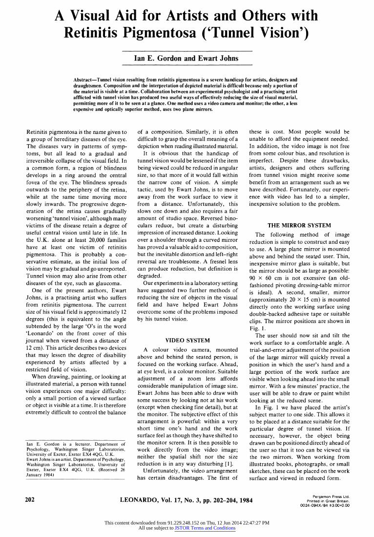
The following method of image reduction is simple to construct and easy to use. A large plane mirror is mounted above and behind the seated user. Thin, inexpensive mirror glass is suitable, but the mirror should be as large as possible: 90 x 60 cm is not excessive (an old- fashioned pivoting dressing-table mirror is ideal). A second, smaller, mirror
(approximately 20 X 15 cm) is mounted directly onto the working surface using double-backed adhesive tape or suitable
clips. The mirror positions are shown in
Fig. 1. The user should now sit and tilt the
work surface to a comfortable angle. A trial-and-error adjustment of the position of the large mirror will quickly reveal a
position in which the user's hand and a large portion of the work surface are visible when looking ahead into the small mirror. With a few minutes' practice, the user will be able to draw or paint whilst looking at the reduced scene.
In Fig. 1 we have placed the artist's subject matter to one side. This allows it to be placed at a distance suitable for the particular degree of tunnel vision. If necessary, however, the object being drawn can be positioned directly ahead of the user so that it too can be viewed via the two mirrors. When working from illustrated books, photographs, or small sketches, these can be placed on the work surface and viewed in reduced form.
LEONARDO, Vol. 17, No. 3, pp. 202-204, 1984 Pergamon Press Ltd.
Printed in Great Britain. 0024-094X/84 $3.00+0.00
202
This content downloaded from 91.229.248.152 on Thu, 12 Jun 2014 22:47:27 PMAll use subject to JSTOR Terms and Conditions
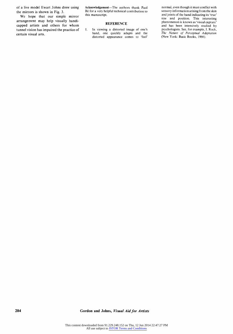
reduction factor R of the object size ho to the final image size hi is approximated by the equation
R= h _ + 2dm R- _ Ih- de
The explanatory optical diagrams are a slightly simplified depiction of the actual working system: in practice the mirrors are slightly offset to prevent the user's head from blocking the image.
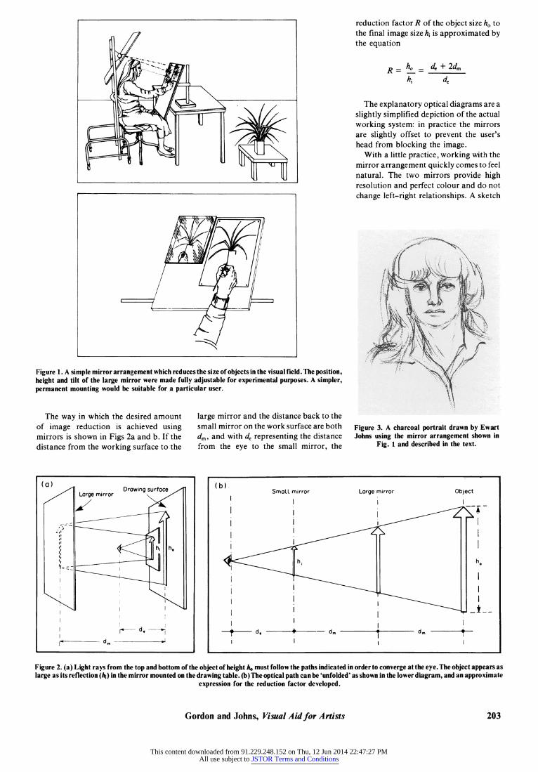
With a little practice, working with the mirror arrangement quickly comes to feel natural. The two mirrors provide high resolution and perfect colour and do not change left-right relationships. A sketch
Figure 1. A simple mirror arrangement which reduces the size of objects in the visual field. The position, height and tilt of the large mirror were made fully adjustable for experimental purposes. A simpler, permanent mounting would be suitable for a particular user.
The way in which the desired amount of image reduction is achieved using mirrors is shown in Figs 2a and b. If the distance from the working surface to the
large mirror and the distance back to the small mirror on the work surface are both d,, and with de representing the distance from the eye to the small mirror, the
Figure 3. A charcoal portrait drawn by Ewart Johns using the mirror arrangement shown in
Fig. 1 and described in the text.
(a) (b) (b)
SmalL mirror
I I
i I
I .
I
i I
i I - d. + dm + d.
I I
Figure 2. (a) Light rays from the top and bottom of the object of height ho must follow the paths indicated in order to converge at the eye. The object appears as large as its reflection (A) in the mirror mounted on the drawing table. (b)The optical path can be 'unfolded' as shown in the lower diagram, and an approximate
expression for the reduction factor developed.
Gordon and Johns, Visual Aid for Artists
Large mirror
I
Object I
(a)
I l I
d m !
I1 de ..Il
203
This content downloaded from 91.229.248.152 on Thu, 12 Jun 2014 22:47:27 PMAll use subject to JSTOR Terms and Conditions
of a live model Ewart Johns drew using the mirrors is shown in Fig. 3.
We hope that our simple mirror
arrangement may help visually handi-
capped artists and others for whom tunnel vision has impaired the practice of certain visual arts.
Acknowledgement-The authors thank Paul Re for a very helpful technical contribution to this manuscript.
REFERENCE
1. In viewing a distorted image of one's hand, one quickly adapts and the distorted appearance comes to 'feel'
normal, even though it must conflict with sensory information arising from the skin and joints of the hand indicating its 'true' size and position. This interesting phenomenon is known as 'visual capture' and has been intensively studied by psychologists. See, for example, I. Rock, The Nature of Perceptual Adaptation (New York: Basic Books, 1966).
Gordon and Johns, Visual Aid for Artists 204
This content downloaded from 91.229.248.152 on Thu, 12 Jun 2014 22:47:27 PMAll use subject to JSTOR Terms and Conditions


