double block & bleed -...
TRANSCRIPT

DOUBLE BLOCK& BLEED
PLUG VALVES

Galli&Cassina is aprominent ItalianCompany mainlyinvolved in themanufacture of acomplete range ofLubricated Plug Valves.The company is
located in Solaro nearMilan (Italy) withextensive offices andworkshop covering
a12.000 sq.mt. areaincluding 5.000 sq.mt.of covered space.
years the companygradually directed itsproduction towardsthe newly bornChemical industry; itwas the first in Italy toproduce valves instainless steeland other new materialcooperating with thedemand of the mostimportant chemicalCompanies.
It was not possibleto expand the Milanfactory any more whichwas built in 1930 andenlarged after thesecond world war.For this reason in 1991Galli&Cassina movedto a new factory inSolaro (Milan) with avery modern plantequipment, verycomfortable for theworkers.After 30 years of
experience in chemicalvalves, Galli&Cassinastarted the productionof Plug Valves in theOil&Gas businessbecoming one of themost significantsuppliers for allInternational Gas&OilCompanies all over theworld.Its sales activity
MILANO
BERGAMOBRESCIA
BOLOGNA
GENOVA
TORINO
MALPENSA
A1
A2
A7
A8
A4
Galli&Cassina Profile
Galli&Cassina wasestablished in1919, andit is one of the oldestItalian companies stillinvolved in themanufacturing of valves.At this early stage thebusiness activity wasconcentrated in theproduction of valves fordomestic and industrialpurposes.After the first ten

covers most of thecontinents with aleading and growingpresence in Europe,Middle East, North &South America and FarEast resulting in a salesand service networkwithsubsidiaries, branchoffices and distributors,acquiring a reputationon high qualityworkmanship as wellas on the reliability ofits products.Special care is due
to the development inevery aspect of theCompany’smanagement,complying with thecontinuous changes,requested by theevolution of theInternational markets.The proved
technical, productive,
Galli&Cassina’sQuality AssuranceSystem ISO 9001- 2000 has beenassessed,approved andcertified by Lloyd’sRegister, while the API
6D and 6Amonogramhave beencertified byAPI (AmericanPetroleum
Institute) - Washington(U.S.A.).Nowadays
Galli&Cassina is proudto celebrate its 90years, presence in theworld of the valvemarket.Galli&Cassina’s
historical backgroundand experience allowthe Company to offerstrong professionalismand a comprehensiverange service.That will surely
guarantee results inthe future.
and financialcapabilities combinedwith the experience ofhuman resources arethe result ofGalli&Cassinareputation all over theworld.
Double Block 5-10_Layout 1 23/10/12 09.59 Pagina 3

4
IndexCompany Profile 2-3Index 4
Galli&Cassina ProductsProduct Identification System 6Special Features Coating overlay 7Material Selection Guide 8Applicable Standard-Specification 9Standard Features 10Plug PTFE Antifriction TreatmentSpecial Features Coating & Overlay 10ANSI Class 150 (PN 20) 11ANSI Class 300 (PN 50) 12ANSI Class 600 (PN 100) 13ANSI Class 900 (PN 150) 14ANSI Class 1500 (PN 250) 15ANSI Class 2500 (PN 420) 16API 6A-2000-3000-5000-10000 17Hydraulic Pressure Test Duration 18and Pressure Test Tables inAccordance with API598 & API 6DQuality Assurance Programme 19Quality Assurance System 20
Engineering DataLubricantsClimax Hydraulic Gun N. 1699 21Climax Lubricants 22Fire Safe Test & Available test 23Temperature Conversion Table 24Pressure/Temperature Rating 25according to ASME B16.34-1996Chemical and Mechanical Requirements 26-27Forged/ bar Materials for Body, Plug, Cover and Stem ComponentsChemical and Mechanical Requirements 28-29Cast Materials for Body, Plug andCover ComponentsQualification of other Size 30Valves - API 6FAQualification of other Pressure Rating Valves
The data reported in this catalogue referto the International Standards applicableat the time of its issue date.Galli&Cassina reserves the right to modifyits products without any obligation to notify,provide or install such modification onproducts previously or subsequently sold.However Galli&Cassina will use the bestafford to keep the customers informedof any changes made.
Double Block 5-10_Layout 1 23/10/12 09.59 Pagina 4

5
Double Block & Bleed Plug Valve
Three -dimensional CAD systemand the Finite Element Modelling allowthe optimization of every stepof valve’s design:
• FEM stress calculation of the pressurecontaining parts (A)
• Raw Casting design• Final Assembly Design Check
A
Double Block 5-10_Layout 1 23/10/12 10.00 Pagina 5

6
Introduction
Product Indentification SystemIdentification numbers here shown are used tp describe essential features of Galli&Cassina valves
Example: 200 DRR06R0001
• 1” 025 • 6” 150 • 16” 400• 11/2 040 • 8” 200 • 18” 450
200 Size • 2” 050 • 10” 250 • 20” 500• 3” 080 • 12” 300• 4” 100 • 14” 350
D Valve Type • D Double Block & Bleed
R Pattern • R Reduce bore• F Full bore
Valve • C Lever • A Actuator (Pneumatic or gas overoil)R Operator • R Gear • B Bare Stem
Type • E Gear with Electric Motor
API 6DValves API 6AValvesWorking • 150 01 • 300 03 • 2000 20 • 3000 30
06 Pressure • 400 04 • 600 06 • 5000 50 • 10000 00Class • 900 09 • 1500 15 • 15000 1K
• 2500 25
R Valve End • R RF Flange • J Ring Joint Flange
Connections • W Butt Weld • C Clamp• B Butt Weld by flange • N Pups
0001 Internal Material • According to client’s materialsIndentification (TRIM) • requirement
The Code used as sample above (200 DRR06R 0001) identifies a: DN 200 (8”) - Double Block & Bleed Valve -Reduce bore - Gear Operator - ANSI 600 - Flanged RF ends connections - Standard carbon steel materials,suitable for ambient and high temperature service.
Galli & Cassina is proud to announce a NEW DOUBLEBLOCK & BLEED plug valve series. The addition of this API-6D compliant design is another major contribution Galli &Cassina’s Plug valve line.The Double Block and Bleed valves present similar featuresas the Galli & Cassina “Single Plug” series.These are marketed with Reduced or Full bore, full conduit,pig-able design.All plug valves are with Standard or Pressure balanced plugs.The Double Block and Bleed valve is developed to meet theindustry demand for an alternate to other design where theservice often develop problems with leakage in the seatingareas. These problems are eliminated with the DBB valveas the plug valve does not have conventional seats as ingate or ball valves.The DBB valve offers two plugs in one body, but maintainthe face-to-face as per API-6D.Therefore it is possible to replace other valves with API-6Df-f dimensions. An added feature is the substantiallyreduced weight compared to a conventional where threeindividual valves are installed to obtain the same feature.
Applications are mainly in the O & G sector where specialfeatures often are required, due to severe operatingconditions.According to API-6D these valves must warrant “Zero-leakage” at maximum differential across the valve.The transportation of Hydrocarbon gasses or Crude Oilwhich may contain H2S, CO2 or other contaminants oftencreate serious corrosion problems in valves. For thisreason Galli & Cassina offer a wide range of specialtymaterials in accordance with NACE or special customerrequirements.To resolve the industry problems with corrosion, erosionand abrasive services under severe operating conditionsGalli & Cassina offer an extensive range of “hard facematerials” as Stellite, Inconel and Tungsten Carbide andothers as Duplex, 6Mo or Nickel alloy.The hard facing is applied in the Galli & Cassina factoryusing own automatic welding robot’s and under strictcontrol of the R&D and QA Department. Galli & Cassina is aISO 9001 approved facility and hold API-6A and API-6D(with monogram) approvals.
Double Block 5-10_Layout 1 23/10/12 10.00 Pagina 6

7
Hardfacing
Galli & Cassina’sresearching, developmentand investment inhardfacing materialsagainst corrosion orabrasion attack, incooperation withspecialized companiesand external laboratories,have given the right
Electroless NickelPlating
The transport of wethydrocarbon gasescontaminated withhydrogen sulphide, carbondioxide or other similarfluids containingappreciable level ofsulphur, can create variouscorrosion problems tosome component in plugvalves.These environments arenot always recognizedunder service conditions,therefore in order to obtaina high quality corrosion
experience to apply inown workshop byautomatic welding robotmachines all kind ofoverlay (Stellite, Inconel,Duplex, 6MO, Nickel alloyand Tungsten Carbide) oneach component of thevalve directly. Theseperformance areespecially highlighted incase of severe operating
conditions. Moreover,higher hardness valuesgreater than 1100 HV/70HRC) compared tostandard hardfacing(Stellite 6, with 37-40HRC hardness) provide avery good abrasion &wear resistance. All theoverlay applications arecontrolled by NDE test,such as LP UT PMI and
thickness check,witnessed by G&C QualityControl inspectors orcustomer’s inspectorsupon request.The improvement of thewelding quality canguarantee an highperformance of G&C plugvalves in Off-Shore/On-Shore Petrochemical andDrilling applications.
Tungsten CarbideCoating
A series of metal carbidecoatings (WC+Ni, Cr or
WC+Co or WC+Co, Cr),usually known as TungstenCarbide (TCC) allows toachieve higher performancein terms of valve working life.
These performances arespecially highlighted in caseof severe operatingconditions. Moreover, higherhardness values (greater
than 1100 HV / 70 HRC)compared to standardhardfacing (Stellite 6, 37 - 40HRC) provide a very goodabrasion & wear resistance.
resistant, all the materialfor each component of thevalves, are selected inaccordance with therequirements of NACE-Std.MR-01-75 Latest Edition.Moreover the use of anelectroless nickel platingon plug surface providesmore corrosion protectionto hydrogen sulphidecrack-resistant base metal.Standard ENP is inaccordance with ASTMB733 Std with a minimun0.003” (76 Microns)thickness, unless otherwisespecified in the customer’sspecification.
Figure A
UPPER HOLE
LOWERHOLE
Standard Features: the Pressure Balance SystemThe operating system ofPressure Balanced PlugValves (shown in Fig.A)consist in the pressureequalization between theport area and thetop/bottom of the plugwith two holes.The upper hole connectsthe plug port area with thetop of the plug, while thelower maintains thepressure equalizationbetween the port area andthe bottom of the plug. ThePressure Balance Systemensure line pressure actson the plug to reduce thevalve torque and avoid thepossibility of plug seizure,even after a prolongedtime in the open or closedposition.The tapered shape of the
plug guarantees that theforce created by linepressure pushes the plugagainst the body seat. Asdifferential pressureincrease so does thesealing capability of thePressure Balanced PlugValve. Thanks to pressurebalance feature, and to theintegral metal to metaldesign, Plug Valve canalways be opened againstthe maximum deltapi.No by-pass is necessary topreserve seat integrity.Periodic lubricantinjection, and seatadjustment can be carriedout when the Plug Valve isunder full pressure. Onlysevere seat damage willcause a reduction of valvesealing.
Special Features: Coating & Overlay
Double Block 5-10_Layout 1 23/10/12 10.00 Pagina 7
8
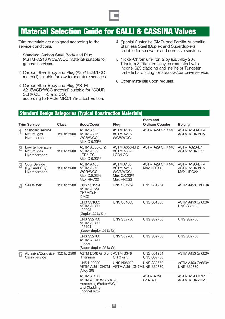
Stem andTrim Service Class Body/Cover Plug Oldham Coupler Bolting
Standard service ASTM A105 ASTM A105 ASTM A29 Gr. 4140 ASTM A193-B7MNatural gas 150 to 2500 ASTM A216 ASTM A216 ASTM A194-2HMHydrocarbons WCB/WCC WCB/WCC
Max C 0.25%
Low temperature ASTM A350-LF2 ASTM A350-LF2 ASTM A29 Gr. 4140 ASTM A320-L7Natural gas 150 to 2500 ASTM A352 ASTM A352- ASTM A194 Gr.7Hydrocarbons LCB/LCC LCB/LCC
Max C 0.23%
Sour Service ASTM A105 ASTM A105 ASTM A29 Gr. 4140 ASTM A193-B7M(H2S and CO2) 150 to 2500 ASTM A216 ASTM A216 Max HRC22 ASTM A194-2HMHydrocarbons WCB/WCC WCB/WCC MAX HRC22
Max C.0.23% Max C.0.23%Max HRC22 Max HRC22
Sea Water 150 to 2500 UNS S31254 UNS S31254 UNS S31254 ASTM A453 Gr.660AASTM A 351CK3MCuN(6MO)
UNS S31803 UNS S31803 UNS S31803 ASTM A453 Gr.660AASTM A 890 UNS S32760J92205(Duplex 22% Cr)
UNS S32750 UNS S32750 UNS S32750 UNS S32760ASTM A 890J93404(Super duplex 25% Cr)
UNS S32760 UNS S32760 UNS S32760 UNS S32760ASTM A 890J93380(Super duplex 25% Cr)
Abrasive/Corrosive 150 to 2500 ASTM B348 Gr 3 or 5ASTM B348 UNS S31254 ASTM A453 Gr.660ASlurry service (Titanium) GR 3 or 5 UNS S32760
UNS N08020 UNS N08020 UNS S32750 ASTM A453 Gr.660AASTM A351CN7M ASTMA351CN7MUNS S32760 UNS S32760(Alloy 20)
ASTM A 105 ASTM A 29 ASTM A193 B7MASTM A 216 WCB/WCC Gr 4140 ASTM A194 2HMHardfacing (Stellite/WC)and Cladding(Inconel 625)
Standard Design Categories (Typical Construction Materials)
Trim materials are designed according to theservice conditions.
1 Standard Carbon Steel Body and Plug.(ASTM-A216 WCB/WCC material) suitable forgeneral services.
2 Carbon Steel Body and Plug (A352 LCB/LCCmaterial) suitable for low temperature services.
3 Carbon Steel Body and Plug (ASTMA216WCB/WCC material) suitable for “SOURSERVICE”(H2S and CO2)according to NACE-MR.01.75/Latest Edition.
Material Selection Guide for GALLI & CASSINA Valves4 Special Austenitic (6MO) and Ferritic-AusteniticStainless Steel (Duplex and Superduplex)suitable for sea water and corrosive services.
5 Nickel-Chromium-Iron alloy (i.e. Alloy 20), Titanium & Titanium alloy, carbon steel withInconel 625 cladding and stellite or Tungstencarbide hardfacing for abrasive/corrosive service.
6 Other materials upon request.
Double Block 5-10_Layout 1 23/10/12 10.00 Pagina 8

9
Applicable Standard-Specification
API 6A Specification for wellhead and christmas tree equipment.
API 6D Specification for PipelineValves.
API 6FA Specification for Fire Testfor Valves.
API RP6F Recommended - Practicefor Fire Test for Valves.
API 598 Valve Inspection and Testing.
API 599 Steel Plug Valves Flangedor Butt Welding Ends.
ASME/ANSI B 16.5 Pipe Flanges and Flanged Fittings.
ASME/ANSI B 16.10 Face-to-Face and End-to-End Dimensions of Valves.
ASME/ANSI B 16.25 Buttwelding Ends.
ASME/ANSI B 16.34 Valves-Flanged, threated and Welding Ends.
ASME/ANSI B 31.3 Chemical Plant and Petroleum Refinery Piping.
ASME/ANSI B 31.4 Liquid Trasportation Systemfor Liquid Petroleum Gas.
ASME/ANSI B 31.8 Gas Transmission and Distribution Piping System.
ASME Boiler and Pressure VesselSECTION VIII - DIV.1 & 2
ASME Boiler and Pressure VesselSection V.
ASNT-TC-1A Reccommended Practicefor Personnel Qualificationand Certification in Non destructive Testing.
BS 1504 Specification for SteelCasting for Pressure Purposes.
BS 2080 Face to Face - Centre to Face- End to End - Steell Valves.
BS 5353 Specification for SteelPlug Valves.
BS 6755 part 1 Testing of Valves (Spec. for Production Pressure Testing Requirements).
BS 6755 part 2 Testing of valves (Spec. for Fire Safe Testing Requirements).
CSA Z 245. 15 Canadian StandardAssociation.
MSS-SP6 Standard Finish for contactFace of Pipe Flanges.
MSS-SP25 Standard Marking Systemfor Valves.
MSS-SP44 Steel Pipe Line Flanges.
MSS-SP53 Quality Standard for SteelCasting-Magnetic ParticleExamination Method.
MSS-SP54 Quality Standard for SteelCasting-Radiographic Examination Method.
MSS-SP55 Quality Standard for Steel Casting Visual Method.
MSS-SP61 Pressure Testing of SteelValves.
NACE Std. MR 01.75 National Association ofLatest Edition Corrosion Engineers.
ASTM American Society forTesting and Materials.
Lubricated Plug Valves are designed to use with most refining services according to API 599 or BS 5353norms whichever is applicable. API 6D norm aims to standardize the materials as well as instructions tomanufacture valves suitable for energy transportation in the pipelines.
Double Block 5-10_Layout 1 23/10/12 10.00 Pagina 9

10
s The purpose of the above test is to prove that Galli&Cassinaantifriction treatment made on plug surface, is guaranteedeven after 30,000 cycles (open/closed position).
Carbon Steel plugs aresubjected to the followingtreatments:A) Case hardening.B) Antifriction treatment.The case hardening hasthe purpose to increase
Plug with PTFEAntifriction treatment.
Plug without PTFEAntifriction treatment.
Plug with PTFEAntifriction treatment.
Plug without PTFEAntifriction treatment.
Standard Features: Plug PTFE Antifriction Treatmentonly the hardness of theplug surface which issubjected to wearing,keeping at the sametime the mechanicalproperties of the basematerial unchanged.
Consequently the basematerial has moretoughness and resistanceagainst impacts.The Antifrictiontreatment is basicallycarried out on the plug
to obtain the followingadvantages:
– Low friction betweenplug and body.
– Low torque.– Wear resistance.– Resistance to seizure.
Double Block 5-10_Layout 1 23/10/12 10.00 Pagina 10

11
ANSI Class 150 (PN 20)
Face To FaceRF B 267 343 432 546 622 661 762 889 991 1092 1194
RTJ B 279 355 445 558 635 674 774 902 1004 1104 1209
Flange Diameter O 152 191 229 279 343 406 483 533 597 635 699
Flange Thickness C 16 19 24 26 29 30 32 35 37 40 43
Top of Stem toCenter Line E 180 220 240 250 – – – – – – –Body Cap toCenter Line F 120 165 180 210 270 320 365 380 400 420 470Center Line Valveto CL Operator T – – – 280 320 370 420 420 420 450 500Handwheel Diameter G – – – 560 560 560 560 500 700 700 700Lenght of Wrench L 450 500 750 – – – – – – – –Size of Bleed ConnectionMSS SP 45 1/2” 1/2” 1/2” 1/2” 3/4” 3/4” 3/4” 1” 1” 1” 1”
Size NPS 2 3 4 6 8 10 12 14 16 18 20DN 50 80 100 150 200 250 300 350 400 450 500
Other size upon request
Double Block 5-10_Layout 1 23/10/12 10.00 Pagina 11

12
ANSI Class 300 (PN 50)
Face To Face * * * * *RF B 283 387 457 559 686 826 864 889 991 1092 1194
RTJ B 298 403 473 575 702 841 881 905 1006 1108 1213
Flange Diameter O 165 210 254 318 381 445 521 584 648 711 775
Flange Thickness C 22 29 32 37 42 48 51 54 58 61 64
Top of Stem toCenter Line E 180 220 240 – – – – – – – –Body Cap toCenter Line F 120 165 180 220 285 320 380 400 430 460 510Center Line Valveto CL Operator T – – – – 330 370 430 445 450 490 540Handwheel Diameter G – – – 560 560 560 700 700 700 700 800Lenght of Wrench L 500 750 750 – – – – – – – –Size of Bleed ConnectionMSS SP 45 1/2” 1/2” 1/2” 1/2” 3/4” 3/4” 3/4” 1” 1” 1” 1”
Size NPS 2 3 4 6 8 10 12 14 16 18 20DN 50 80 100 150 200 250 300 350 400 450 500
* Face to face not in accordance with API 6D - ASME B16.10Other size upon request
Double Block 5-10_Layout 1 23/10/12 10.00 Pagina 12

13
ANSI Class 600 (PN 100)
Face To FaceRF B 292 356 432 559 660 787 838 889 991 1092 1194
RTJ B 295 359 435 562 664 791 841 892 994 1095 1200
BW B 292 356 432 559 660 787 838 889 991 1092 1194
Flange Diameter O 165 210 273 356 419 508 559 603 686 743 813
Flange Thickness C 26 32 38 48 56 64 67 70 77 83 89
Top of Stem toCenter Line E 180 220 240 – – – – – – – –Body Cap toCenter Line F 120 165 180 250 300 320 390 412 455 480 520Center Line Valveto CL Operator T – – 280 295 350 380 420 565 650 680 700Handwheel Diameter G – – 560 560 700 800 800 800 800 800 800Lenght of Wrench L 500 750 1000 – – – – – – – –Size of Bleed ConnectionMSS SP 45 1/2” 1/2” 1/2” 1/2” 3/4” 3/4” 3/4” 1” 1” 1” 1”
Size NPS 2 3 4 6 8 10 12 14 16 18 20DN 50 80 100 150 200 250 300 350 400 450 500
Other size upon request
Double Block 5-10_Layout 1 23/10/12 10.00 Pagina 13

14
ANSI Class 900 (PN 150)
Face To Face *RF B 368 381 457 610 737 838 965 1029 1130 1219 1321
RTJ B 371 384 460 613 740 841 968 1038 1140 1232 1334
BW B 368 381 457 610 737 838 965 1029 1130 1219 1321
Flange Diameter O 216 242 292 381 470 546 610 642 705 787 857
Flange Thickness C 38 38 45 56 64 70 80 86 89 102 108
Top of Stem toCenter Line E 180 220 – – – – – – – – –Body Cap toCenter Line F 130 180 190 200 270 350 380 430 470 485 500Center Line Valveto CL Operator T – – 250 260 335 380 450 495 590 595 600Handwheel Diameter G – – 560 560 560 700 700 700 800 800 800Lenght of Wrench L 500 750 – – – – – – – – –Size of Bleed ConnectionMSS SP 45 1/2” 1/2” 1/2” 1/2” 3/4” 3/4” 3/4” 1” 1” 1” 1”
Size NPS 2 3 4 6 8 10 12 14 16 18 20DN 50 80 100 150 200 250 300 350 400 450 500
* Face to face not in accordance with API 6D - ASME B16.10Other size upon request
Double Block 5-10_Layout 1 23/10/12 10.00 Pagina 14

15
ANSI Class 1500 (PN 250)
Face To Face *RF B 368 470 546 705 832 991 1130 1257 1384 1537 1664
RTJ B 371 473 549 711 841 1000 1146 1276 1406 1559 1686
BW B 368 470 546 705 832 991 1130 1257 1384 1537 1664
Flange Diameter O 216 267 311 394 483 584 673 749 825 914 984
Flange Thickness C 38 48 54 83 92 108 124 133 146 162 178
Top of Stem toCenter Line E 210 235 – – – – – – – – –Body Cap toCenter Line F 180 190 200 225 280 390 440 490 530 545 560Center Line Valveto CL Operator T – – 250 265 370 400 530 580 610 630 640Handwheel Diameter G – – 560 560 700 700 700 800 800 800 800Lenght of Wrench L 750 1000 – – – – – – – – –Size of Bleed ConnectionMSS SP 45 1/2” 1/2” 1/2” 1/2” 3/4” 3/4” 3/4” 1” 1” 1” 1”
Size NPS 2 3 4 6 8 10 12 14 16 18 20DN 50 80 100 150 200 250 300 350 400 450 500
* Face to face not in accordance with API 6D - ASME B16.10Other size upon request
Double Block 5-10_Layout 1 23/10/12 10.00 Pagina 15
16
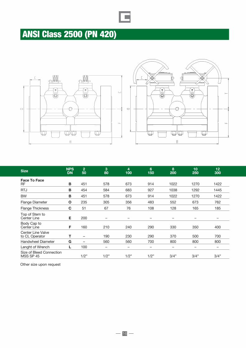
ANSI Class 2500 (PN 420)
Face To FaceRF B 451 578 673 914 1022 1270 1422
RTJ B 454 584 683 927 1038 1292 1445
BW B 451 578 673 914 1022 1270 1422
Flange Diameter O 235 305 356 483 552 673 762
Flange Thickness C 51 67 76 108 128 165 185
Top of Stem toCenter Line E 200 – – – – – –Body Cap toCenter Line F 160 210 240 290 330 350 400Center Line Valveto CL Operator T – 190 230 290 370 500 700Handwheel Diameter G – 560 560 700 800 800 800Lenght of Wrench L 100 – – – – – –Size of Bleed ConnectionMSS SP 45 1/2” 1/2” 1/2” 1/2” 3/4” 3/4” 3/4”
Size NPS 2 3 4 6 8 10 12DN 50 80 100 150 200 250 300
Other size upon request
Double Block 5-10_Layout 1 23/10/12 10.00 Pagina 16

17
API 6A - 2000 - 3000 - 5000 - 10000
Face To FaceRTJ B 295 333 359 435 562 371 422 384 460 613
Flange Diameter O 165 190 210 273 356 216 245 241 292 381
Flange Thickness C 26 29 32 38 48 38 42 38 45 56
Top of Stem to Center Line E 180 180 220 – – 180 180 218 – –Body Cap to Center Line F 120 120 150 170 200 150 130 170 175 200Center Line Valve to CL Operator T – – – 270 280 – – – 270 260Handwheel Diameter G – – – 560 560 – – – 560 560Lenght of Wrench L 500 750 1000 – – 750 750 1000 – –Size of Bleed ConnectionMSS SP 45 1/2” 1/2” 1/2” 1/2” 3/4” 1/2” 1/2” 1/2” 1/2” 3/4”
Size NPS 21/16 29/16 31/8 41/16 71/16 21/16 29/16 31/8 41/16 71/16DN 52 65 79 103 179 52 65 78 103 179
API 2000 - Reduced API 3000 - Reduced
Face To FaceRTJ B 371 422 473 549 711 – – – – – – – –
Flange Diameter O 216 245 267 311 394 188 200 232 270 316 357 480 480
Flange Thickness C 38 42 48 54 83 37 38 45 51 62 70 92 92
Top of Stem to Center Line E 180 210 218 – – 190 – – – – – – –Body Cap to Center Line F 150 180 220 175 225 – 152 172 192 220 270 305 305Center Line Valveto CL Operator T – – 270 270 265 205 210 220 230 248 350 390 390Handwheel Diameter G – – 2580 560 710 – – – 710 710 710 800 800Lenght of Wrench L 750 1000 – – – 450 750 1000 – – – – –Size of Bleed ConnectionMSS SP 45 1/2” 1/2” 1/2” 3/4” 1” 1/2” 1/2” 1/2” 1/2” 3/4” 1” 1” 1”
Size NPS 21/16 29/16 31/8 41/16 71/16 113/16 21/16 29/16 31/16 41/16 51/8 71/16x63/8 71/16DN 52 65 79 103 179 46 52 65 78 103 130 179x162 179
API 5000 - Reduced API 10000 - Full Bore
API 10000 - FULL BOREUPON REQUEST
SIZE: 1 13/16” UP TO 7 1/16”
Double Block 5-10_Layout 1 23/10/12 10.00 Pagina 17

18
15 - 50 1/2 - 2 15 sec. 15 sec.65 - 150 2 1/2 - 6 60 sec. 60 sec.200 - 300 8 - 12 120 sec. 120 sec.350 and over 14 and over 300 sec. 120 sec.
Valve Size Test DurationDN (mm) NPS (Inches) Shell Seat (1)
Valve Size Test DurationDN (mm) NPS (Inches) Shell Seat (1)
API 598 API 6D / ISO 14313
(1) Duration applicable also for the pneumatic seat test (5.5 bar / 80 psi).
15 - 100 1/2 - 4 2 min. 2 min.150 - 250 6 - 10 5 min. 5 min.300 - 450 12 - 18 15 min. 5 min.500 and over 20 and over 30 min. 5 min.
Hydraulic Pressure Test Duration In accordance with API 6D and API 598
ASME B16.34 Group Material 1.1
(A 105; A 216 WCB; A 350 LF2)Working Pressures by Classes, psig (Bar)
150 PN20 300 PN50 600 PN100 900 PN150 1500 PN250 2500 PN420Working pressure rating 285 (20) 740 (51) 1480 (102) 2220 (153) 3705 (255) 6170 (425)Hydraulic body test 450 (31) 1125 (78) 2225 (153) 3350 (231) 5575 (384) 9275 (640)Hydraulic seat test 314 (22) 814 (56) 1628 (112) 2442 (168) 4076 (281) 6787 (468)
ASME B16.34 Group Material 1.2 and 2.8
(A 350 LF6; A 216 WCC; A 352 LCC; A182 F44/ F51; UNS S31803/S31254/S32750; A 351 Gr. CK3MCuN / CE8MN/ CD4MCu / CD3MWCuN)
Working Pressures by Classes, psig (Bar)150 PN20 300 PN50 600 PN100 900 PN150 1500 PN250 2500 PN420
Working pressure rating 290 (20) 750 (52) 1500 (103) 2250 (155) 3750 (259) 6250 (431)Hydraulic body test 450 (31) 1125 (78) 2250 (155) 3375 (233) 5625 (388) 9375 (646)Hydraulic seat test 319 (22) 825 (57) 1650 (114) 2475 (171) 4125 (284) 6875 (474)
ASME B16.34 Group Material 1.3
(A 352 LCB) Working Pressures by Classes, psig (Bar)150 PN20 300 PN50 600 PN100 900 PN150 1500 PN250 2500 PN420
Working pressure rating 265 (18) 695 (48) 1390 ( 96) 2085 (144) 3470 (239) 5785 (399)Hydraulic body test 400 (28) 1050 (72) 2100 (145) 3150 (217) 5225 (360) 8700 (600)Hydraulic seat test 292 (20) 765 (53) 1529 (105) 2294 (158) 3817 (263) 6364 (439)
ASME B16.34 Group Material 2.1 and 2.2
(A 182 F304; A 479 Gr. 304; A 351 CF3; A 351 CF8; A 182 F316; A 479 Gr. 316; A 351 CF3M)
Working Pressures by Classes, psig (Bar)150 PN20 300 PN50 600 PN100 900 PN150 1500 PN250 2500 PN420
Working pressure rating 275 (19) 720 (50) 1440 (99) 2160 (149) 3600 (248) 6000 (414)Hydraulic body test 425 (29) 1100 (76) 2175 (150) 3250 (224) 5400 (372) 9000 (621)Hydraulic seat test 303 (21) 792 (55) 1584 (109) 2376 (164) 3960 (273) 6600 (455)
ASME B16.34 Group Material 2.3
(A 182 F304/F316L; A 479 Gr.304/316L) Working Pressures by Classes, psig (Bar)150 PN20 300 PN50 600 PN100 900 PN150 1500 PN250 2500 PN420
Working pressure rating 230 (16) 600 (41) 1200 ( 83) 1800 (124) 3000 (207) 5000 (345)Hydraulic body test 350 (24) 900 (62) 1800 (124) 2700 (186) 4500 (310) 7500 (517)Hydraulic seat test 253 (17) 660 (46) 1320 ( 91) 1980 (137) 3300 (228) 5500 (379)
Working High PressurePressure Body Seat Gas TestRating Up to13 5/8” From 16 3/4” Body & Seat
Bar psi Bar psi Bar psi Bar psi Bar psi138 2000 276 4000 207 3000 138 2000 138 2000207 3000 415 6000 310 4500 207 3000 207 3000345 5000 517 7500 517 7500 345 5000 345 5000690 10000 1035 15000 1035 15000 690 10000 690 100001035 15000 1550 22500 1550 22500 1035 15000 1035 150001380 20000 2070 30000 1380 20000 1380 20000
Pressure Test Tables in Accordance with API598 & API 6D
Pressure Test Tables in Accordance with API6A
Double Block 5-10_Layout 1 23/10/12 10.00 Pagina 18

Quality Assurance Programme
Double Block 5-10_Layout 1 23/10/12 10.00 Pagina 19

20
Quality Assurance DevelopmentSince 1981 Galli&Cassinais authorized to use themonograms of AmericanPetroleum Institute (licence N. 6D - 0049.1)(licence N. 6A - 0520).As a guarantee andcertification of the QualityAssurance Program implemented, Galli&Cassina has thequality system issued byLloyd’s Register certifyingthat Galli&Cassina Quality System conforms to the European StandardISO 9001: 2000, API Spec.Q1, and is always subjectby internal/ external auditto be in compliance with
the customerrequirements.In addition Galli&CassinaPlug Valves are incompliancewith CEPressureEquipmentDirective PEDN. 97/23/ECand ATEX (N. 94/9 /EC) for productsintended for use inpotentiallyexplosiveatmospheres.
Quality Assurance System
QUALITY
ASSURANCE
MANUAL
GALLI&CASSINAPlugValves.
Customer ServiceGalli&Cassina’s CustomerService is always willing toassist the customer with a prompt response to“service” requests. Full after sales servicesassistance can be offeredeither at our workshop or on site testing,spare parts supply;
Training programs,on operation and safety;Final-Documentation.
After 90 years ofmanufacturing experienceand latest technology,Galli&Cassina QualityAssurance System hasbeen assessed, approvedand certified against thefollowing quality assurancestandards: ISO 9001-Vision 2000 and API Q1.Rigorous procedures andinternal audits guaranteethat the Quality System isimplemented at all stages,starting from incoming rawmaterials, production,inspection, assembly, final
test, packing andshipping.Every product is designedand manufactured toconform to uniformlyhigh standards. These standards areassured by a qualitymanagement systemwhich includes ISO 9001certification and testing ofall products prior toshipment. Advanceddesign, durableconstruction materials andrigid manufacturing standard provide valves
you can rely on for yearsof trouble-freeperformance. Since itsbeginning in 1919,Galli&Cassina hasmaintained itscommitmentto quality product andsatisfied customers.Our focus on productvariety, technicalexpertise andcompany supportremains constant,
from drawing board touser satisfaction, ourcommitment is continuous.
Double Block 5-10_Layout 1 23/10/12 10.00 Pagina 20

Climax Hydraulic Gun No.1699
21
Galli&Cassina Plug Valves canbe provided with aspecial automatic lubricant pump tofacilitatelubricationmaintenance service.The automaticpump modeldepends on the si-ze of valve and itsnumber ofopen/closed cycles enables
us to calculate theconsumption of the lubricant grease during the operating service. The automaticpumps are available either electric or pneumatic motortype at the following operatingtemperature range:-20 to 40°C.
Automatic Lubrication
Galli&Cassina PlugValves can use differenttypes of Climax lubricantgrease suitable forvarious services.The operating conditionsmust be specified atenquiry stage enablingus to advise which typeof sealant is suitable.The lubricant grease isavailable as a spare partitem and can be orderedas:
• Cartridges (suitablefor hydraulic gunpump).
• Drums (suitable forpneumatic pump).For the selection ofthe correct lubricant,Galli&Cassina staff isalways available at thecustomer’s request torecommend thesuitable lubricant.
This specially designed,high pressure handgun,light in weight (appr.16lbs.)is more rugged thanconventional types andmeets exacting demandsof plug valve sealants. Built for servicing plug valves, all parts aremachined with minutyeaccuracy.The polished hardenedsteel piston is perfectlyfitted in the high pressurebarrel to provide absolutesmoothness of operation.The CLIMAX 1699 is self-priming and can be usedin any position. Becauseof its hydraulic principle,this gun exerts morepressure than any otherportable gun.This gun is equippedwith a CLIMAX 1699Button Head Coupler forconnection to the buttonhead sealant fitting in theshank of the valve.This coupler has abuilt - in feature whichlocks it to fitting when thegun is under positivepressure. The coupler cannot beconnected to or separatedfrom the fitting withthe gun under pressure. This pressure may berelieved by a turn of theby-pass valve on the gun. The by-pass valveshould not be closed to apoint where it is jammedinto its seat, nor should itbe opened tight againstthe stop.
gun from injury if theoperator were to
continue to pump after thegun had beendepleted of valvesealant.Also, to preventdamage to the valveand sealant gun, in the
event of sealant cloggingthe system or the operatorpumping too fast, aCLIMAX 15000 psi gaugeis optional equipment.This accessory indicatesthe point at which sufficientsealant pressure has beendeveloped within thevalve. The gauge also indicatesvalve adjustment andother services required.The CLIMAX 0-15000 psigauge is the highestquality, most reliableglycerin filled gaugeavailable.The one piece die castbrass case and heavy dutybourdon tube andmovement enable thegauge to stand up to theshock and vibrationencountered on the mostdemanding applications.The CLIMAX gauge alsofeatures a rubber gaugeprotector.A carrying case for theCLIMAX Model 1699 isoptional.Refer to the part list foravailable options.Note: Gun shown is a1699-S model completewith hose assembly,gauge, tee and “Z” swivel.
The valve should be closedfirmly, but no tightly.It is not necessary to openthe valve past one full turn. Due to “built - in” safety features, the CLIMAX 1699
provides the maximumsafety to both the valveand the gun itself.The hydraulic system ofthe gun is equipped witha relief fitting to protect the
Lubricants
Double Block 5-10_Layout 1 23/10/12 10.00 Pagina 21

22
Lubricant Type Color Temp. Range Principal Unsuitableand No. Available From To Services For
220 Stick Clear -75 to 250 °F Very cold service for Aromatic,Bulk -59 to 121 °C pipe lines, compressor Solvents.
stations, gasoline plants and crude oilproduction fields.For Liquid Service.
262 Stick -85 to 250 °F Same as above-Gas LPG-65 to 121 °C Service.
400 Stick Red -20 to 450 °F Acids and Caustics. LiquidBulk -29 to 232 °C Hydrocarbons.
600 Stick Tan -20 to 500 °F General gas and LPGBulk Brown -29 to 260 °C general Hydrocarbons
service.
650 Stick Blue-Green -40 to 500 °F Hydrocarbon and Aromatic,Bulk -40 to 260 °C L.P.G. service Alkalies
Solvents.
711 Stick White 32 to 400 °F Aviation gasoline, Jet 100% Benzine.Bulk 0 to 204 °C fuel, fuel blends of
Alkylate.
750 Stick Black 0 to 600 °F Asphalt hot oil service Aromatic, Bulk -18 to 316 °C Salt brine, high Alkalies
temperature steam. Solvents.
800 Stick White -20 to 450 °F Butane, Butadiene, AlkaliesBulk -29 to 232 °C Carbon Tetrachloride,
Ethane, Propane.
900 Stick Black -20 to 650 °F Natural gas, AlkaliesBulk -29 to 343 °C petrochemical
plants, rubberplants, and hotHydrocarbonsservice.
901 Stick Black -30 to 300 °F Cold weather, AlkaliesBulk -34 to 149 °C Hydrocarbon
lubricant.
950 Stick Amber -40 to 300 °F Propylenes, Benzenes AlkaliesBulk -40 to 149 °C Toulene, Butadiene,
Xylenes, Styrene, Cumenes
1034-MT Stick Cream -20 to 400 °F Liquid and gaseous. AlkaliesBulk -29 to 204 °C Aliphatic hydrocarbon
service. (wet or dry natural gas)
Climax Lubricants
Double Block 5-10_Layout 1 23/10/12 10.00 Pagina 22

23
Fire Safe Test
Available TestsType of Test Applicable Standards Performance
X AND GAMMA RAYS ANSI B16.34 - Annex-B 100% all butt welding endsASME VIII - Div.1 - MSS - SP 54 and body.ASTM E446 - E186 - E280
DYE PENETRANT ASME V - art.6 and 24 - ASTM E142 100% All butt welding endsANSI B16.34 - Annex-DMSS-SP-93
MAGNETIC - PARTICLES ASME V - art.7 and 25 100% of all valves(Dry and wet) ANSI B16.34 - Annex C - MSS - SP 53
ULTRASONIC ASME V - art.4 and 23 Upon customer requestASME VIII - Div.1 - ASTM - A388
VISUAL AND DIMENSIONAL MSS - SP 55 100% of rough and finishedANSI B16.5 - B16.10 machined componentsAPI 6D - (Table 4.2) and assembled valves
HARDNESS NACE - MR.01.75 Latest Edition 100% of wetted components
HYDROSTATIC AND API - 6D - API 598 100% of all valvesPNEUMATIC BS 6755 - Part.1 - MSS - SP 61
OPERATION TORQUE API - 6D Upon customer request
HIGH PRESSURE CLOSURE API - 598 - Par. 4-5 Upon customer request
POSITIVE MATERIAL ASTM A751 100% of pressure containingIDENTIFICATION components
All Galli&Cassina’s PlugValves have been testedagainst fire resistence,according to API - 6FAand BS 6755 - Part 2standards andwitnessed byinternational third party.
Metal to Metal Seat,diaphragm sealing aswell as the stem sealingcompound with graphiteguarantees a highreliability performanceof our Plug Valves whilein exposure to Fire Testconditions.
Double Block 5-10_Layout 1 23/10/12 10.00 Pagina 23

24
Temperature Conversion Table
-273 -459.4 43.3 110 230.0-268 -450 46.1 115 239.0-240 -400 48.9 120 248.0-212 -350 54.4 130 266.0-184 -300 60.0 140 284.0-157 -250 -418 65.6 150 302.0-129 -200 -328 71.1 160 320.0-101 -150 -238 76.7 170 338.0- 73 -100 -148 82.2 180 356.0- 45.6 - 50 - 58.0 87.8 190 374.0- 42.8 - 45 - 49.0 93.3 200 392.0- 40.0 - 40 - 40.0 98.9 210 410.0- 37.2 - 35 - 31.0 104.4 220 428.0- 34.4 - 30 22.0 110.0 230 446.0- 31.7 - 25 - 13.0 115.6 240 464.0- 28.9 - 20 - 4.0 121.0 250 482.0- 26.1 - 15 5.0 149.0 300 572.0- 23.2 - 10 14.0 177.0 350 662.0- 20.6 - 5 23.0 204.0 400 752.0- 17.8 0 32.0 232.0 450 842.0- 15.0 5 41.0 260.0 500 932.0- 12.2 10 50.0 288.0 550 1022.0- 9.4 15 59.0 316.0 600 1112.0- 6.7 20 68.0 343.0 650 1202.0- 3.9 25 77.0 371.0 700 1292.0- 1.1 30 86.0 399.0 750 1382.00 32 89.6 427.0 800 1472.07.7 35 95.0 454.0 850 1562.04.4 40 104.0 482.0 900 1652.07.2 45 113.0 510.0 950 1742.010.0 50 122.0 538.0 1000 1832.012.8 55 131.0 566.0 1050 1922.015.6 60 140.0 593.0 1100 2012.018.3 65 149.0 621.0 1150 2102.021.1 70 158.0 649.0 1200 2192.023.9 75 167.0 677.0 1250 2282.026.7 80 176.0 704.0 1300 2372.029.4 85 185.0 732.0 1350 2462.032.2 90 194.0 762.0 1400 2552.035.0 95 203.0 788.0 1450 2642.037.8 100 212.0 816.0 1500 2732.040.6 105 221.0
°C °F °C °F
NOTE: The temperature to be converted is the figure in the yellow column.To obtain a reading in °C use left column; for conversion to °F use the right column.
°F = 9 °C+325
°C = 5 (°F-32)9
Double Block 5-10_Layout 1 23/10/12 10.00 Pagina 24

25
Pressure/TemperatureRatingAccording to ASME B16.34-2009
Temperature Working Pressures by Classes, psig (Bar)°F (°C) 150 300 600 900 1500 2500
-20 to 10 (-29 to 38) 285 (20) 740 (51) 1.480 (102) 2.220 (153) 3.705 (255) 6.170 (425)200 ( 93) 260 (18) 680 (47) 1.360 ( 94) 2.035 (140) 3.395 (234) 5.655 (390)300 (149) 230 (16) 655 (45) 1.310 ( 90) 1.965 (135) 3.270 (225) 5.450 (377)400 (204) 200 (14) 635 (44) 1.265 ( 87) 1.900 (131) 3.170 (219) 5.280 (364)500 (260) 170 (12) 605 (42) 1.205 ( 83) 1.810 (125) 3.015 (208) 5.025 (346)600 (316) 140 (10) 570 (39) 1.135 ( 78) 1.650 (114) 2.840 (196) 4.730 (326)650 (343) 125 ( 9) 550 (38) 1.100 ( 76) 1.650 (114) 2.745 (189) 4.575 (315)700 (371) 110 ( 8) 530 (37) 1.060 ( 73) 1.590 (110) 2.665 (184) 4.425 (305)
Temperature Working Pressures by Classes, psig (Bar)°F (°C) 150 300 600 900 1500 2500
-20 to 10 (-29 to 38) 265 (18) 695 (48) 1.395 (96) 2.090 (144) 3.480 (240) 5.805 (400)200 ( 93) 255 (18) 655 (45) 1.320 (91) 1.980 (137) 3.300 (228) 5.505 (380)300 (149) 230 (16) 640 (44) 1.275 (88) 1.915 (132) 3.190 (220) 5.315 (366)400 (204) 200 (14) 615 (42) 1.230 (85) 1.845 (127) 3.075 (212) 5.125 (353)500 (260) 170 (12) 585 (40) 1.175 (81) 1.760 (121) 2.930 (202) 4.885 (337)600 (316) 140 (10) 550 (38) 1.105 (76) 1.655 (114) 2.755 (190) 4.595 (317)650 (343) 125 ( 9) 535 (37) 1.065 (73) 1.600 (110) 2.665 (184) 4.440 (306)700 (371) 110 ( 8) 510 (35) 1.025 (71) 1.535 (106) 2.560 (177) 4.270 (294)
Material: ASTM A 105, ASTM A 216 Gr. WCB, ASTM A 350 Gr. LF2 (Table 2-1.1)
Material: ASTM A 216 Gr. WCC, ASTM A 352 Gr. LCC/LC2/LC3 (Table 2-1.2)
Material: ASTM A 352 Gr. LCB (Table 2-1.3)
Material: ASTM A182 Gr. F316/F316H,ASTM A 479 Gr. 316/316H, ASTM A 351Gr.CF3M/CF8M (Table 2-2.2)
Temperature Working Pressures by Classes, psig (Bar)°F (°C) 150 300 600 900 1500 2500
-20 to 10 (-29 to 38) 290 (20) 750 (52) 1.500 (103) 2.250 (155) 3.750 (259) 6.250 (431)200 ( 93) 260 (18) 750 (52) 1.500 (103) 2.250 (155) 3.750 (259) 5.250 (431)300 (149) 230 (16) 730 (50) 1.455 (100) 2.185 (151) 3.640 (251) 6.070 (419)400 (204) 200 (14) 705 (49) 1.410 ( 97) 2.110 (145) 3.520 (243) 5.865 (404)500 (260) 170 (12) 665 (46) 1.330 ( 92) 1.995 (138) 3.325 (229) 5.540 (382)600 (316) 140 (10) 605 (42) 1.210 ( 83) 1.815 (125) 3.025 (209) 5.040 (348)650 (343) 125 ( 9) 590 (41) 1.175 ( 81) 1.765 (122) 2.940 (203) 4.905 (338)700 (371) 110 ( 8) 555 (38) 1.110 ( 77) 1.705 (118) 2.775 (191) 4.630 (319)
Temperature Working Pressures by Classes, psig (Bar)°F (°C) 150 300 600 900 1500 2500
-20 to 10 (-29 to 38) 275 (19) 720 (50) 1.440 (99) 2.160 (149) 3.600 (248) 6.000 (414)200 ( 93) 235 (16) 620 (43) 1.240 (85) 1.860 (128) 3.095 (213) 5.160 (356)300 (149) 215 (15) 560 (39) 1.120 (77) 1.680 (116) 2.795 (193) 4.660 (321)400 (204) 195 (13) 515 (36) 1.025 (71) 1.540 (106) 2.570 (177) 4.280 (295)500 (260) 170 (12) 480 (33) 955 (66) 1.435 ( 99) 2.390 (165) 3.980 (274)600 (316) 140 (10) 450 (31) 900 (62) 1.355 ( 93) 2.255 (155) 3.760 (259)650 (343) 125 ( 9) 440 (30) 885 (61) 1.325 ( 91) 2.210 (152) 3.680 (254)700 (371) 110 ( 8) 435 (30) 870 (60) 1.305 ( 90) 2.170 (150) 3.620 (250)
Double Block 5-10_Layout 1 23/10/12 10.00 Pagina 25

26
(1) For each reduction of 0,01% below the specibed maximun carbon content, an increase of 0,06% Mnabove the specified maximun will be pemmitted up to a maximun of 1,35%.
(2) Cu + Ni + Cr + Mo ≤1,00%
Composition % (Maximum Percent Unless Range is Given)
CarbonSteel
Low Alloy
Martensitic
AusteniticStainlessSteel
Agehardened SS
Titanium
NickelAlloy
AusteniticFerritic
Stainless Steel
ASTM Standard Nominal (UNS designation) Composition C Mn P S Si
A 105 (1) (2) (3) 0,35 0,60 - 1,05 0,035 0,040 0,10-0,35
A 350 LF1 (2) (3) 0,30 0,60-1,35 0,035 0,040 0,15-0,30
A 350 LF2 (2) (3) 0,30 0,60 - 1,35 0,035 0,040 0,15- 0,30
A 350 LF3 (3) 0,20 0,90 0,035 0,040 0,20-0,35
A 29 Gr.4140 0,38 - 0,43 0,75 - 1,00 0,035 0,040 0,15- 0,35
A 29 Gr.4340 0,38-0,43 0,60-0,80 0,035 0,040 0,15-0,35
A 182 F1 (UNS K12822) C-Mo 0,28 0,60-0,90 0,045 0,045 0,15-0,35
A 182 F2 (UNS K12122) 0,5Cr-0,5Mo 0,05-0,21 0,30-0,80 0,040 0,040 0,10-0,60
A 182 F5a (UNS K42544) 5Cr 0,25 0,60 0,040 0,030 0,50
A 182 F9 (UNS K90941) 9Cr 0,15 0,30-0,60 0,030 0,030 0,50-1,00
A 182 F11 CL.3 (UNS K11572) 1,25Cr-0,5Mo 0,10-0,20 0,30-0,80 0,040 0,040 0,50-1,00
A 182 F12 CL.2 (UNS K11564) 1Cr-0,5Mo 0,10-0,20 0,30-0,80 0,040 0,040 0,10-0,60
A 182 F22 CL.3 (UNS K21590) Cr-Mo 0,05-0,15 0,30-0,60 0,040 0,040 0,50
A182 F6a CL.2 (UNS S41000) 13Cr 0,15 1,00 0,040 0,030 1,00
A 182 F6NM (UNS S41500) 13Cr-4Ni 0,05 0,5-1,0 0,030 0,030 0,60
A 182 F304 (4) (UNS S30400) 18Cr-8Ni 0,08 2,00 0,045 0,030 1,00
A 182 F304H (4) (UNS S30409) 18Cr-8Ni 0,04-0,10 2,00 0,045 0,030 1,00
A 182 F304L (4) (UNS S30403) 18Cr-8Ni 0,035 2,00 0,045 0,030 1,00
A 182 F316 (4) (UNS S31600) 18Cr-10Ni-Mo 0,08 2,00 0,045 0,030 1,00
A 182 F316H (4) (UNS S31609) 18Cr-10Ni-Mo 0,04-0,10 2,00 0,045 0,030 1,00
A 182 F316L (4) (UNS S31603) 18Cr-10Ni-Mo 0,030 2,00 0,045 0,030 1,00
A 182 F310 (UNS S31000) 25Cr-20Ni 0,25 2,00 0,045 0,030 1,00
A 182 F44 (UNS S31254) 20Cr-18Ni-6Mo 0,020 1,00 0,030 0,010 0,80
B 462- UNS N08020 (ALLOY 20) 29Ni-20Ni-3Cu-2Mo 0,07 2,00 0,045 0,035 1,00
A 182 F51 (UNS S31803) 22Cr-5Ni 0,030 2,00 0,030 0,020 1,00
A 182 F53 (UNS S32750) 25Cr-7Ni-4Mo 0,030 1,20 0,035 0,020 0,80
A 182 F55 (UNS S32760) (5) 25Cr-7Ni-3,5Mo 0,030 1,00 0,030 0,010 1,00
A 564 Gr 630 H900 (UNS S17400) 16Cr-4Ni-4Cu 0,07 1,00 0,040 0,030 1,00
A 564 Gr 630 H1150M (UNS S17400) 16Cr-4Ni-4Cu 0,07 1,00 0,040 0,030 1,00
B 348 Gr.3 (Unalloyed Titanium) Ti 0,08 Ti=Balance H=0,015 Fe=0,30 O=0,35
B 348 Gr.5 (Titanium Alloy) 6Al-4V 0,08 Ti=Balance H=0,015 Fe=0,40 O=0,20
B 564-UNS N06625 (INCONEL 625) 60Ni-22Cr-9Mo-3,5Cb 0,10 0,5 0,015 0,015 0,5
B 564-UNS N08825 (INCONEL 825) 0,05 1,0 0,03 0,5
Chemical and Mechanical Requirements - Forged / bar
Double Block 5-10_Layout 1 23/10/12 10.00 Pagina 26

27
Mechanical Properties
(3) Cr + Mo ≤ 0,32%(4) Maximum nitrogen content of 0,10%(5) Pitting Resistance Equivalent Number (PREN) = Cr + 3,3Mo + 16N ≤ 40 .
Tensile Yield Reduction Others Strengh Strengh Elongation of area Cr Mo Ni Cu V Elements min, ksi (MPa) min, ksi (MPa) min% min%
0,30 0,12 0,40 0,40 0,08 Cb = 0,02 70 (485) 36 (250) 22 30
0,30 0,12 0,40 0,40 0,08 Cb=0,02 60 (415) 30 (205) 25 38
0,30 0,12 0,40 0,40 0,08 Cb=0,02 70 (485) 36 (250) 22 30
0,30 0,12 3,3 - 3,7 0,40 0,03 Cb=0,02 70 (485) 37,5 (260) 22 35
0,80-1,10 0,15-0,25 - - - - 100 (690) 75 (520) 20 50
0,70-0,90 0,20-0,30 1,65-2,00 - - - 115 (790) 96 (660) 16 45
- 0,44-0,65 - - - - 70 (485) 40 (275) 20 30
0,50-0,81 0,44-0,65 - - - - 70 (485) 40 (275) 20 30
4,0-6,0 0,44-0,65 0,50 - - - 90 (620) 65 (450) 22 50
8,0-10,0 0,90-1,10 - - - - 85 (585) 55 (380) 20 40
1,00-1,50 0,44-0,65 - - - - 75 (515) 45 (310) 20 30
0,80-1,25 0,44-0,65 - - - - 70 (485) 40 (275) 20 30
2,00-2,50 0,87-1,13 - - - - 75 (515) 45 (310) 20 30
11,5-13,5 - 0,50 - - - 85 (585) 55 (380) 18 35
11,5-14,0 0,5-1,0 3,5-5,5 - - - 115 (790) 90 (620) 15 45
18,0-20,0 - 8,0-11,0 - - - 75 (515) 30 (205) 30 50
18,0-20,0 - 8,0-11,0 - - - 75 (515) 30 (205) 30 50
18,0-20,0 - 8,0-13,0 - - - 70 (485) 25 (170) 30 50
16,0-18,0 2,00-3,00 10,0-14,0 - - - 75 (515) 30 (205) 30 50
16,0-18,0 2,00-3,00 10,0-14,0 - - - 75 (515) 30 (205) 30 50
16,0-18,0 2,00-3,00 10,0-15,0 - - - 70 (485) 25 (170) 30 50
19,0-22,0 - 24.0-26,0 - - - 75 (515) 30 (205) 30 50
19,5-20,5 6,0-6,5 17,5-18,5 0,5-1,0 - N=0,18-0,22 94 (650) 44 (300) 35 50
19,00-21,00 2,00-3,00 32,00-38,00 3,00-4,00 - - 80 (551) 35 (241) 30 50
21,0-23,0 2,5-3,5 4,5-6,5 - - N=0,08-0,20 90 (620) 65 (450) 25 45
24,0-26,0 3,0-5,0 6,0-8,0 0,5 - N=0,24-0,32 116 (800) 80 (550) 15 -
24,0-26,0 3,0-4,0 6,0-8,0 0,50-1,00 N=0,20-0,30 W=0,50-1,00 109 (750) 80 (550) 25 45
15,0-17,5 - 3,00-5,00 3,00-5,00 - - 190 (1.310) 170 (1.170) 10 40
15,0-17,5 - 3,00-5,00 3,00-5,00 - - 115 (795) 75 (515) 18 55
- - - - - N=0,05 65 (450) 55 (380) 18 30
Al=5,5-6,75 - - - 3,5-4,5 N=0,05 130 (895) 120 (828) 10 25
20,0-23,0 8,0-10,0 58,0Min Ta+Cb=3,15-4,15 Ti=0,4 Fe=5,0Al=0,4 110 (758) 50 (345) 25 -
19,5-23,5 2,5-3,5 38,0-46,0 1,5-3,0 Ti=0,6-1,2 Fe=22,0Al=0,2 85 (586) 35 (241) 30 -
Materials for Body, Plug, Cover and Stem Components
Double Block 5-10_Layout 1 23/10/12 10.00 Pagina 27

28
(1) Grade CF8C shall have a columbium content of not less than 8 times the carbon content but not over 1,00%(2) For each reduction of 0,01% below the specibed maximun carbon content, and increase of 0,04% Mn above
the specified maximun will be pemmitted up to a maximun of: 1,28% for WCB and LCB; 1,40% for WCC andLCC.
Composition % (Maximum Percent Unless Range is Given)
ASTM Standard Nominal (UNS designation) Composition C Mn P S Si
A 216 WCB (2) 0,30 1,00 0,04 0,045 0,60
A 216 WCC (2) 0,25 1,20 0,04 0,045 0,60
A 352 LCB (UNS J03003) (2) 0,30 1,00 0,04 0,045 0,60
A 352 LCC (UNS J02505) (2) 0,25 1,20 0,04 0,045 0,60
A 352 LC3 (UNS J31550) 3,5Ni 0,15 0,50-0,80 0,04 0,045 0,60
A 487 Gr4Q 4-C Ni-Cr-Mo 0,03 1,00 0,04 0,045 0,80
A 217 WC1 C-Mo 0,25 0,50-0,80 0,04 0,045 0,60
A 217 WC6 Cr-Mo 0,05-0,20 0,50-0,80 0,04 0,045 0,60
A 217 WC9 Cr-Mo 0,05-0,18 0,40-0,70 0,04 0,045 0,60
A 217 C5 Cr-Mo 0,20 0,40-0,70 0,04 0,045 0,75
A 217 C12 Cr-Mo 0,20 0,35-0,65 0,04 0,045 1,00
A 217 CA15 (UNS J91150) 13Cr 0,15 1,00 0,04 0,04 1,50
A 487 CA6NM (UNS J91540) 13Cr-4Ni 0,06 1,00 0,04 0,03 1,00
A 351 CF3 (UNS J92500) 18Cr-8Ni 0,03 1,50 0,04 0,04 2,00
A 351 CF3M (UNS J92800) 16Cr-12Ni-2Mo 0,03 1,50 0,04 0,04 1,50
A 351 CF8 (UNS J92600) 18Cr-8Ni 0,08 1,50 0,04 0,04 2,00
A 351 CF8C (UNS 92710) (1) 18Cr-10Ni-2Co 0,08 1,50 0,04 0,04 2,00
A 351 CF8M (UNS J92900) 16Cr-12Ni-2Mo 0,08 1,50 0,04 0,04 1,50
A 351 CN7M (UNS N08007) 29Ni-20Cr-3Cu-2Mo 0,07 1,50 0,04 0,04 1,50
A 351 CK3MCuN (UNS J93254) (3) 20Cr-18Ni-6Mo-N 0,025 1,20 1,00 0,010 0,045
A 890 CD3MN (UNS J92205) 22Cr-5Ni-Mo-N 0,03 1,50 0,04 0,020 1,00
A 890 CE3MN (UNS J93404) (3) 25Cr-7Ni-Mo-N 0,03 1,50 0,04 0,04 1,00
A 890 CD3MWCuN (UNS J93380)(3) 25Cr-7Ni-Mo-N 0,03 1,00 0,030 0,025 1,00
A 193 B7 and B7M (5) Cr-Mo 0,37-0,49 0,65-1,10 0,035 0,040 0,15-0,35
A 193 B16 Cr-Mo-V 0,36-0,47 0,45-0,70 0,035 0,040 0,15-0,35
A 193 B8M CL.2 18Cr-10Ni-2Mo 0,08 2,00 0,045 0,030 1,00
A 320 L43 Ni-Cr-Mo 0,38-0,43 0,60-0,85 0,035 0,040 0,15-0,35
A 320 L7 and L7M (5) Cr-Mo 0,38-0,48 0,75-1,00 0,035 0,04 0,15-0,35
A 453 Gr 660A 0,08 2,00 0,040 0,030 1,00
A 194 2H/2HM C min 0,40 1,00 0,040 0,050 0,40
A 194 4 C-Mo 0,40-0,50 0,70-0,90 0,035 0,040 0,15-0,35
A 194 7/7M Cr-Mo 0,37-0,49 0,65-1,10 0,035 0,040 0,15-0,35
A 194 8M 18Cr-10Ni-2Mo 0,08 2,00 0,045 0,030 1,00
CarbonSteel
Low Alloy
Martensitic
AustenicStainlessSteel
Cast AusteniticFerritic (Duplex)Stainless Steel
Stud
Nut
Chemical and Mechanical Requirements - Cast Materials
Chemical and Mechanical RequirementsBolting Materials
Double Block 5-10_Layout 1 23/10/12 10.00 Pagina 28

29
Mechanical Properties
(3) Pitting Resistance Equivalent Number (PREN) = Cr + 3,3Mo + 16N ≤ 40.(4) For 3/4” (M20) and under: 110/(760), 95/(655) 15; over 3/4” (M20) up to 1” (M24): 100/(690), 80/(550), 20 over 1” M24 up to 1.25”
(M30) 95/(655), 65/(450), 25 over 1.25” (M30) up to 1.5” (M36): 90/(620), 50/(345), 30.(5) For B7M and L7M grades, a minimum carbon content of 0,28% is permitted, provided that the required tensile properties are met in
the section size involved.
Tensile Yield Reduction Strengh Strengh Elongation of area Cr Mo Ni Cu V W min, ksi (MPa) min, ksi (MPa) min% min%
0,50 0,20 0,50 0,30 0,03 - 70 (485) 36 (250) 22 35
0,50 0,20 0,50 0,30 0,03 - 70 (485) 40 (275) 22 35
0,50 0,20 0,50 0,30 0,03 - 65 (450) 35 (240) 24 35
0,50 0,20 0,50 - 0,03 - 70 (485) 40 (275) 22 35
0,30-0,60 3,00-4,00 - - - 7 (485) 40 (275) 24 35
0,40-0,80 0,15-0,30 0,4-0,80 0,50 0,03 0,10 90 (620) 60 (415) 18 35
0,35 0,45-0,65 - 0,50 - 0,10 65 (450) 35 (240) 24 35
1,00-1,50 0,45-0,65 0,50 0,50 - 0,10 70 (485) 40 (275) 20 35
2,00-2,75 0,90-1,20 0,50 0,50 - 0,10 70 (485) 40 (275) 20 35
4,00-6,50 0,45-0,65 0,50 0,50 - 0,10 90 (620) 60 (415) 18 35
8,00-10,00 0,90-1,20 0,50 0,50 - 0,10 90 (620) 60 (415) 18 35
11,50-14,00 0,50 1,00 - - - 90 (620) 65 (450) 18 30
11,5-14,0 0,4-1,0 3,5-4,5 0,50 0,05 0,10 100 (690) 75 (515) 17 35
17,00-21,00 0,50 8,00-12,00 - - - 70 (485) 30 (206) 35 -
17,00-21,00 2,00-3,00 9,00-13,00 - - - 70 (485) 30 (206) 30 -
18,00-21,00 0,50 8,00-11,00 - - - 70 (485) 30 (206) 35 -
18,00-21,00 0,50 9,00-12,00 - - - 70 (485) 30 (206) 30 -
18,00-21,00 2,00-3,00 9,00-12,00 - - - 70 (485) 30 (206) 30 -
19,0-22,0 2,0-3,0 27,5-30,5 3,0-4,0 - - 62 (425) 25 (170) 35 -
19,5-20,5 6,0-7,0 17,5-19,5 0,50-1,00 - N=0,18-0,24 80 (550) 38 (260) 35 -
21,0-23,5 2,5-3,5 4,5-6,5 1,00 - N=0,10-0,30 90 (620) 60 (415) 25 -
24,0-26,0 4,0-5,0 6,0-8,0 - - N=0,10-0,30 100 (690) 75 (515) 18 -
24,0-26,0 3,0-4,0 6,5-8,5 0,5-1,0 N=0,20-0,3 0,5-1,0 100 (690) 65 (450) 25 -
0,75-1,20 0,15-0,25 - - - - 125/100 (860/690) 105/80 (720/550) 16/18 50
0,80-1,15 0,50-0,65 - - 0,25-0,35 Al=0,015 125 (860) 105 (725) 18 50
16,0-18,0 2,00-3,00 10,0-14,0 - - - 100 (690) 80 (550) (4) 45
0,70-0,90 0,20-0,30 1,65-2,00 - - - 125 (860) 105 (725) 16 50
0,80-1,10 0,15-0,25 - - - - 125/100 (860/690) 105/80 (725/550) 16 50
13,5-16,0 1,00-1,50 24,0-27,0 - 0,10-0,50 B=0,001-0,01 130 (895) 85 (585) 15 18Ti=1,90-2,35
- - - - - - - - - - - -
- 0,20-0,30 - - - - - - - - - -
0,75-1,20 0,15-0,25 - - - - - - - - - -
A 16,0-18,0 2,00-3,00 10,0-14,0 - - - - - - - - -
for Body, Plug and Cover Components
(Body / Plug)
Double Block 5-10_Layout 1 23/10/12 10.00 Pagina 29
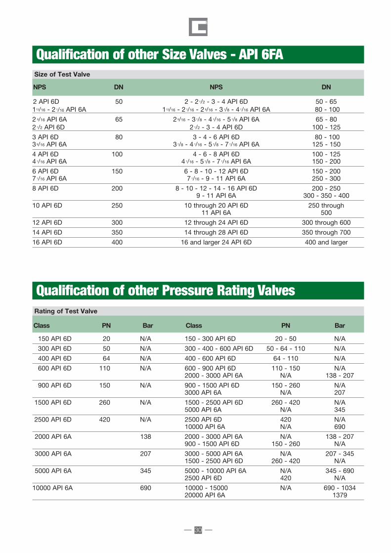
30
Size of Test Valve
Rating of Test Valve
Class PN Bar Class PN Bar
150 API 6D 20 N/A 150 - 300 API 6D 20 - 50 N/A
300 API 6D 50 N/A 300 - 400 - 600 API 6D 50 - 64 - 110 N/A
400 API 6D 64 N/A 400 - 600 API 6D 64 - 110 N/A
600 API 6D 110 N/A 600 - 900 API 6D 110 - 150 N/A2000 - 3000 API 6A N/A 138 - 207
900 API 6D 150 N/A 900 - 1500 API 6D 150 - 260 N/A3000 API 6A N/A 207
1500 API 6D 260 N/A 1500 - 2500 API 6D 260 - 420 N/A5000 API 6A N/A 345
2500 API 6D 420 N/A 2500 API 6D 420 N/A10000 API 6A N/A 690
2000 API 6A 138 2000 - 3000 API 6A N/A 138 - 207900 - 1500 API 6D 150 - 260 N/A
3000 API 6A 207 3000 - 5000 API 6A N/A 207 - 3451500 - 2500 API 6D 260 - 420 N/A
5000 API 6A 345 5000 - 10000 API 6A N/A 345 - 6902500 API 6D 420 N/A
10000 API 6A 690 10000 - 15000 N/A 690 - 103420000 API 6A 1379
NPS DN NPS DN
2 API 6D 50 2 - 2 1/2 - 3 - 4 API 6D 50 - 65 113/16 - 2 1/16 API 6A 113/16 - 2 1/16 - 2 9/16 - 3 1/8 - 4 1/16 API 6A 80 - 100
2 9/16 API 6A 65 29/16 - 3 1/8 - 4 1/16 - 5 1/8 API 6A 65 - 8021/2 API 6D 21/2 - 3 - 4 API 6D 100 - 125
3 API 6D 80 3 - 4 - 6 API 6D 80 - 100 3 9/16 API 6A 31/8 - 4 1/16 - 5 1/8 - 7 1/16 API 6A 125 - 150
4 API 6D 100 4 - 6 - 8 API 6D 100 - 125 4 1/16 API 6A 41/16 - 5 1/8 - 7 1/16 API 6A 150 - 200
6 API 6D 150 6 - 8 - 10 - 12 API 6D 150 - 200 7 1/16 API 6A 71/16 - 9 - 11 API 6A 250 - 300
8 API 6D 200 8 - 10 - 12 - 14 - 16 API 6D 200 - 250 9 - 11 API 6A 300 - 350 - 400
10 API 6D 250 10 through 20 API 6D 250 through 11 API 6A 500
12 API 6D 300 12 through 24 API 6D 300 through 600
14 API 6D 350 14 through 28 API 6D 350 through 700
16 API 6D 400 16 and larger 24 API 6D 400 and larger
Qualification of other Size Valves - API 6FA
Qualification of other Pressure Rating Valves
Double Block 5-10_Layout 1 23/10/12 10.00 Pagina 30

Our productsare being used inthemost importantPlants and GasPipelines all overthe world.
Galli&Cassina PlugValves are used in themost importanthydrocarbon plants andgas pipelines all over theworld.For over 70 years
Galli&Cassina has beencommitted to provideservice to the end-userswith a full range ofproducts ensuring totalcustomer’s satisfaction.
Galli&Cassina isrepresented by salesoffices worldwide andyou are requested tocontact our main officein Italy for more details.
GALLI&CASSINA in the World

G&C DBB-10.2012
Office and Workshop:GALLI & CASSINA S.p.A.
Via Drizza, 30/32 • 20020 SOLARO (MILANO) ItalyPhone: +39.02.96799632/3 • Telefax: +39.02.96799699http://www.gallicassina.it • E-mail: [email protected]