dosimetric calibration of an annular60co gamma-ray source
TRANSCRIPT
Journal of Radioanalytical and Nuclear Chemistry, Articles, Vol. 185, No. 1 (1994) 101-108
DOSIMETRIC CALIBRATION OF AN ANNULAR 6~ GAMMA-RAY SOURCE
S. MILIANIC, D. RA~EM, M. RANOGAJEC-KOMOR
Ruder Bo~kovid lnstitute, 41000 Zagreb, Bijeni~ka c. 54, P.O. Box 1016 (Croatia)
(Received May 26, 1994)
Precise dosimetric calibration of the radiation field of the Gammacell irradiator has been carded out. For measuring spatial dose distribution a cavity ionization chamber in conjuction with a Fanner dosimeter and CaF 2 thermoluminescent dosimeters were used. The results make possible thecalculation of doses received by samples of different sizes and shapes.
Dosimetry is an essential part of experimental design of radiation research experiments. Uniform irradiation of an object is usually required. This can be accomplished by rotating an object in a unilaterally incident field, or by placing an object in a uniform radiation field. Approximately uniform radiation field is obtained inside an annular cavity formed by arranging source pencils along the periphery of a cylinder. The most popular version of this design of irradiator is the Gammacell by Atomic Energy of Canada Limited. The isodose curves inside the irradiation chamber as supplied by the producer I or published in the literature 2,3 are usually separated from each other by 5% or larger intervals. However, in some instances a more detailed mapping of the field depending on the shape and size of irradiated samples is desirable. Also, there are no data in the literature about transit dose (the dose absorbed during the movement of the sample chamber to and from the irradiation position). This dose has to be taken into consideration at doses lower than 10 Gy, i.e., for the majority of experiments in radiobiology because its contribution may be significant.
The aim of this work was a precise dosimetric calibration of the radiation field inside the GammaceU irradiator to enable more precise determination of radiation doses absorbed by samples of different sizes and shapes. This is a continuation of our efforts to publish, for the benefit of the users of our irradiation services, the detailed results of the absorbed dose mapping of various irradiation facilities available at the Radiation Chemistry and Dosimetry Laboratory of the Ruder Bo~ovid Institute.
Previous accounts include the description of two home-made closed type irradiation facilities with manual introduction of samples. The older facility 4 is out of function now. The other nne is still in use as an irradiation facility, and partly serves as a reference irradiator, providing traceability to previous calibrations. 5
Elsevier Science S. A., Lausanne Akadgmiai Kiad6, Budapest
S. MILJANI~et al.: DOSIMETRIC CALIBRATION
A cavity ionization chamber in conjuction with a Farmer dosimeter and CaF 2 thermoluminescent dosimeters (TLD) were used for measurements of spatial dose distribution. The values of transit doses were determined by an ionization chamber~ Also, the uniformity of the radiation field at a radius of 3.6 cm was determined by simultaneous irradiation of several types of chemical dosimeters: Fricke dosimeter, 6 the ethanoFch!orobenzene (ECB) ~ and DL-M4 dosimeter~o ~
Experiment[
Description of gamma-irradiation facility: Gammacell irradiator, Model 220 ~ is a self-contained type of irradiation facility. The unit consists of an annular cage holding the source, surrounded by a lead shielding with a long cylindrical drawer free to move vertically inside both the source and shield. The drawer contains the chamber in which the samples are placed~
The 6~ source consists of 48 linear source elements equidistantly spaced in a stainless steel rack to form a cylindrical shell or annulus, with a diameter of 20.9 cm, measured between the centers of opposing elements. Each linear element consists of a welded stainless steel pencil filled with 6~ in the form of metallic cobalt. Interna~ dimensions of each pencil are 1 cm diameter and 20.3 cm length.
The drawer is centrally located in the radiation shield and is power driven vertically through the center of the source. The material to be inadiated is placed in the sample chamber, then lowered to the irradiation position i.e. the sample chamber is then in the center of the source.
The sample chamber is a hollow, thin-walled cylinder constructed of anodized aluminium. The inside dimensions are 15.2 cm in diameter by 20.6 cm high. A removable door allows acces to the chamber. The sample holder which can be placed into the chamber, consists of a round base plate (13.2 cm diameter) with three vertical rods (17.55 cm high) fixed syrmnetricaUy near the rim of the plate. Other round plates can be slipped upon the rods and fixed at different heights from the base plate. Irradiations in "standard geometry" are performed with plates having 12 holes placed symmetrically at a radius of 3.6 cm so that centers of the holes are 1.9 cm apart. The lower plate has smaller holes so that the test tubes or similar samples rest on it, while being fixed in vertical position by the upper plate with larger holes.
Dosimetric measurements included the determination of absorbed dose distribution vertically along the axis of the sample chamber and at a radius of 3.6 cm, horizontal dose distribution at different heights from the chamber bottom, homogeneity of radiation field at different heights by simultaneous irradiation of dosimeters at a radius of 3.6 cm, and the dose absorbed by samples during their movement to and from the irradiation position.
102
S. MILJANIt~et al.: DOSIMETRIC CALIBRATION
Methods of dosimetry
Ionization chamber: Dosimetric measurements were performed with an ionization chamber type 2581 and a Farmer Dosimeter type 2570 (NE Technology Limited, England). The chamber has a sensitive volume of 0.56 cm 3, outer and inner electrodes are made from Shonka A-150 tissue-equivalent plastic. The build-up cap (outside diameter 1.86 cm), which is used for 6~ gammas, is made from Lucentine (polystyrene-equivalent plastic). Reference point when the build up-cap is on should be
taken as the intersection of the plane through the line engraved on the cap (2 cm from the bottom) and the axis (marked with a dot). Dose is specified as absorbed dose to water (measured in free air). The chamber was calibrated by direct comparison against a National Physics Laboratory NPL Calibrated Secondary Standard Therapy Level Exposure Meter type 2560 and a 0.3 cm 3 thimble ionization chamber type 2561 in a standard radiation beam.
Measurements were performed at different heights from the bottom of the sample chamber along the axis of the chamber and at a radius of 3.6 cm. For each position the
ionization chamber was lowered at least ten times into the irradiation position and time of irradiation was measured by a stop-watch. From linear regression of measured data as a function of time, the slope of the least-squares line gives the dose rate, and y-intercept the transit dose (absorbed during the movement to the irradiation position and from it).
Thermoluminescent dosimetry: Due to their small size (0.45 cm dia x 0.05 cm
thickness), thermoluminescent detectors make possible the measurements of dose distribution inside the sample chamber in truly minute increments of space, where the
measurements with other systems'would give only space averages. CaF 2 : Mn detectors, produced by the Jo~.ef Stefan Institute, Ljubljana, 9 were selected for this purpose. The detectors have good dosimetric characteristics (reproducibility, individual sensitivity,
fading and better sensitivity than other types of TLDs). l~ The detectors were encapsulated in 0.01 cm polyethylene foils placed in 0.35 cm thick rubber holders to ensure electronic equilibrium. Outer dimensions of the holder were: 2.0 cm length, 1.1 cm width and approximately 1 cm thickness. For determination of vertical dose distribution, previously individually calibrated detectors were attached at different heights to the wooden stand placed in the axis of the sample chamber. For horizontal dose distribution, detectors were placed on a round plate at different radii. The readings were taken with a Toledo 654 (Pitman) reader.
Chemical dosimetry systems: For determination of the uniformity of the field for 12 irradiation positions placed radially at a radius of 3.6 cm, ferrous sulfate (Fricke) 6 dosimetric solutions, ethanol-chlorobenzene (ECB) 7 and DL-M4 dosimeters 8 were used.
Fricke dosimeters were irradiated in Pyrex glass test tubes (1.6 cm o. d. • 7.5 cm height) containing 5 cm 3 solution. Twelve Fricke dosimeters were irradiated at a single
t03
s. MILJANI(~et al.: DOSIMETRIC CALIBRATION
height, whereby the active volume of the dosimeter spanned the heights between 4.1 and
7.6 cm in the irradiation chamber (center at h = 5.9 cm). Five irradiations at this height were made.
ECB dosimeters were irradiated in Pyrex glass test tubes (the same as for Fricke
dosimeters) at different heights, so that the horizontal plane through the middle of the
dosimetric solution was Successively occupying the heights of 6.4, 7.3, 8.1 8.6 and
9.6 cm. There was one irradiation at each height.
Twelve DL-M4 dosimeters were irradiated at a single height, with the center
at h = 9.0 cm (active volume of the dosimeter spanning 10 cm between 4.0 and
14.0 cm). Six irradiations of DL-M4 dosimeters were made .
The mean value of the dose rate and the corresponding standard deviation were
calculated for each radial position. In case of ECB dosimeters, the data of all runs at
various heights were averaged, while in the case of Fricke and DL-M4 the averages for different runs at the single heights were used.
Results
The results of vertical dose distribution measured with ionization chamber and TL
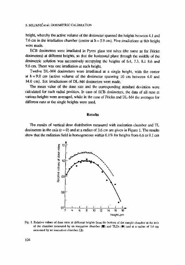
dosimeters in the axis (r = 0) and at a radius of 3.6 cm are given in Figure 1. The results
show that the radiation field is homogeneous within 0.1% for heights from 6.6 to 9.1 cm
A 1.1
0.8
0.5 I I I I I I ~ I I , 4 6 8 I0 12 14 16 18
Height ,crn
Fig. I. Relative values of dose rates at different heights from the bottom of tile sample chamber at the axis of the chamber measured by an ionization chamber (I) and TLDs (0) and at a radius of 3.6 cm measured by an ionization chamber (121)
104
o
>o
"6
i
1.2
1.1
1.0
0.9
S. MIUANI(~et al.: DOSIMETRIC CALIBRATION
a) h = 4.1cm /
/ 4
y = 0 . 9 5 3 . 0 . 0 1 9 x * 0 . 0 0 2 x z R = 0.98 I r f I i I / I
2 4 6 8 Radius ,c m
.~ 1.2
~.o
0.!
b) h =5.5 cm j
y =0.974 +0.019x +0.002x 2 R=0.99 i I i I l I i t i p
2 4 6 o Radius, cm
1.2
1.1
>~ ~.0
y =0.998 § 0.O08x + 0.OO4x 2 R ,,0.99
0.91 l I i I I I I I -0 2 4 6 8
Radius ~cm
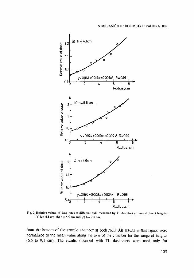
Fig. 2. Relative values of dose rates at different radii measured by TL detectors at three different heights: (a) h = 4.1 cm, (b) h = 5.5 cm and (c) h = 7.8 cm
from the bottom of the sample chamber at both radii. All results in this figure were normalized to the mean value along the axis of the chamber for this range of heights (6.6 to 9.1 cm). The results obtained with TL dosimeters were used only for
105
S. MILIANI~et al.: DOSIMETRIC CALIBRATION
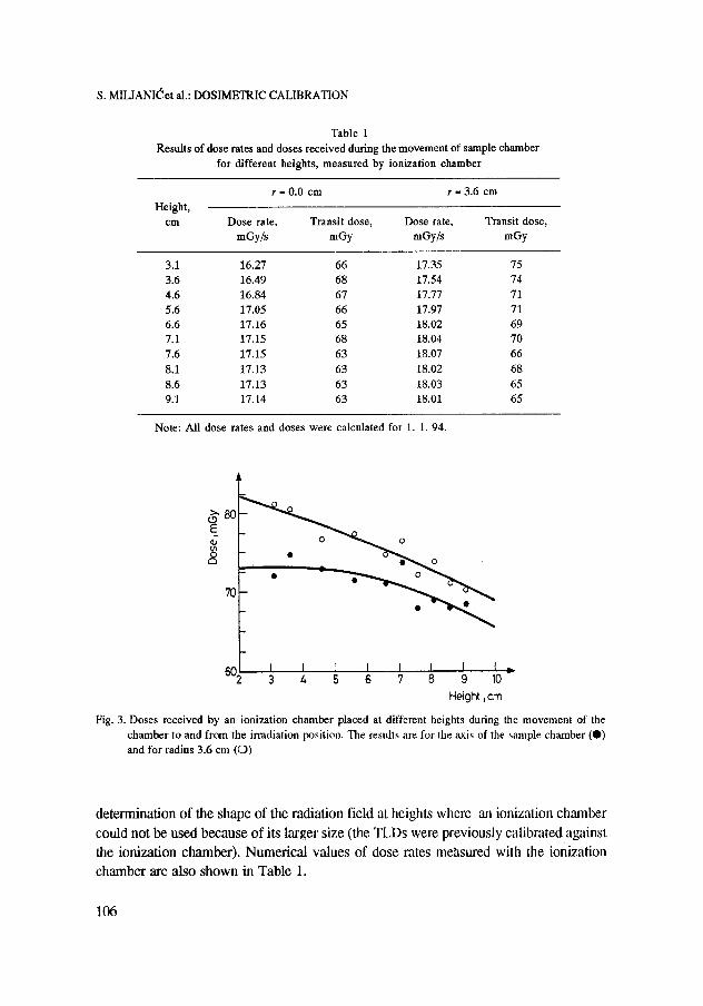
Table 1 Results of dose rates and doses received during the movement of sample chamber
for different heights, measured by ionization ehamber
r s 0.0 cm r - 3.6 cm
Height, cm Dose rate, Transit dose, Dose rate, Transit dose,
mGy/s mGy mGy/s mGy
3.1 16.27 66 17.35 75 3.6 16.49 68 17.54 74 4.6 16.84 67 17.77 71 5.6 17.05 66 17.97 71 6.6 17.16 65 18.02 69 7.1 17.15 68 18.04 70 7.6 17.15 63 18.07 66 8.1 17.13 63 18.02 68 8.6 17.13 63 18.03 65 9.1 17.14 63 18.01 65
Note: All dose rates and doses were calculated for 1. 1.94.
~ 8 0 E
713
02 I I [ I I I I I 3 4 5 6 7 8 9 10-
Height, cm
Fig. 3. Doses received by an ionization chamber placed at different heights during the movement of the chamber to and from the irradiation position. The results are for the axis of tile sample chamber (0) and for radius 3.6 cm (O)
determination of the shape of the radiation field at heights where an ionization chamber could not be used because of its larger size (the TLDs were previously calibrated against the ionization chamber). Numerical values of dose rates measured with the ionization chamber are also shown in Table 1.
106
S. MILJANI(~ et al.: DOSIMETRIC CALIBRATION
The results of horizontal dose distribution measured with TL detectors are shown in
Fig. 2. The distributions were measured at three different heights from the bottom of the sample chamber: 4.1, 5.5 and 7.8 cm, respectively. Each point is a mean value of 3 irradiations. The curves drawn throught the experimental points were obtained by a least-squares fit to a quadratic equation. The doses were normalized to the dose value measured at a height of 7.8 cm in the axis of the chamber.
i
I
I
.20.6cm
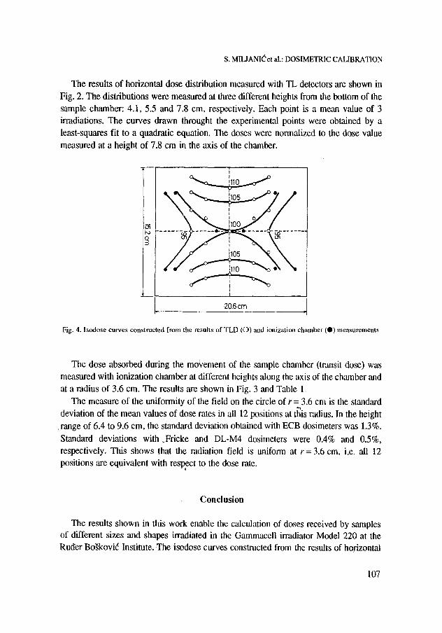
Fig. 4. lsodose curves constructed from the results of TLD (C)) and ionization chamber ( I ) measurements
The dose absorbed during the mo~,ement of the sample chamber (transit dose) was measured with ionization chamber at different heights along the axis of the chamber and at a radius of 3.6 cm. The results are shown in Fig. 3 and Table 1.
The measure of the uniformity of the field on the circle of r = 3.6 cm is the standard deviation of the mean values of dose rates in all 12 positions at this radius. In the height
range of 6.4 to 9.6 cm, the standard deviation obtained with ECB dosimeters was 1.3%.
Standard deviations with .Fricke and DL-M4 dosimeters were 0.4% and 0.5%, respectively. This shows that the radiation field is uniform at r= 3.6 cm, i.e. all 12 positions are equivalent with respect to the dose rate.
Conclusion
The results shown in this work enable the calculation of doses received by samples of different sizes and shapes irradiated in the Gammaceli irmdiator Model 220 at the Ruder Bo~kovi6 Institute. The isodose curves constructed from the results of horizontal
107
s. MILJANIt~et al.: DOSIMETRIC CALIBRATION
and vertical dose distr ibut ions are shown in Fig. 4. These data together with those from
Table 1 enable prec ise calculat ion of doses in every specific case. It is recommended to
irradiate samples at heights from 6.6 to 9.1 cm from the chamber bottom, in which
region the dose rates are approximate ly homogeneous.
References
1. Atomic Energy of Canada Limited, Gammacell 220 Research Irradiator, Specifications Number JS300, Ottawa, 1981.
2. O. A. CURZIO, H. O. QUARANTA, Int. J. Appl. Radiation Isotopes, 33 (1982) 1. 3. H. O. QUARANTA, O. A. CURZIO, Int. J. Al~Pl. Radiation Isotopes, 35 (1984) 65. 4. I. DVORNIK, V. POSAVEC-LUKIN, S. ZILIC, Tehnika, 20 (1965) 2252. (in Croatian with summary in
English) 5. D. RA~EM, Lj. ANDELI(~, I. DVORNIK, High-Dose Dosimetry, Proc. IAEA Symp., IAEA, Vienna, 1985,
p. 143. 6. H. FRICKE, E. J. HART, Radiation Dosimetry, Vol. 2,, Academic Press, New York, 1965, p. 167. 7. I. DVORNIK, Manual on Radiation Dosimetry, Marcel Dekker, New York, 1970, p. 345. 8. D. RA~EM, S. MILJANIC, I. DVORNIK, Ionizing Radiation Protection and Dosimetry, G. PAIC (Ed.),
CRC Press, Boca Raton. 1988, p. 156. 9. F. DRt~AR, G. DRAZI(~, U. MIKLAVZIC," v Proc. 12th Yugoslav Symp. on Radiat. Protection, Yugoslav
Society on Radiat. Protection, Ohrid, 1983, p. 389. 10. M. RANOGAJEC-KOMOR, M. OSVAY, Radiat. Protect. Dosim., 17 (1986) 379.
108