doppler lidar developments - aerospacelab-journal.org · ity, since an agile filter is required to...
TRANSCRIPT
Issue 12 - December 2016 - Doppler LIDAR Developments for Aeronautics AL12-08 1
Testing in Aerospace Research
2 /Rf V λ∆ = , where RV is the so-called radial wind speed (speed projected on the laser line of sight) and λ is the laser wavelength. Doppler LIDARs analyze the frequency of the backscattered signal to obtain the air speed.
This paper deals with wind LIDAR developments at ONERA for aero-nautics applications. Most developments imply Doppler LIDARs, except for long-range clear air turbulence detection. In a first part, we focus briefly on high-altitude wind speed measurements. Such appli-cations have a high potential for in-flight aeronautics, but technologi-cal issues make these developments very challenging. In a second part, we present Coherent Doppler LIDAR, which is the mainstream technology for wind speed measurement from a ground station or from low and medium altitude aircraft.
Direct Detection Doppler LIDAR
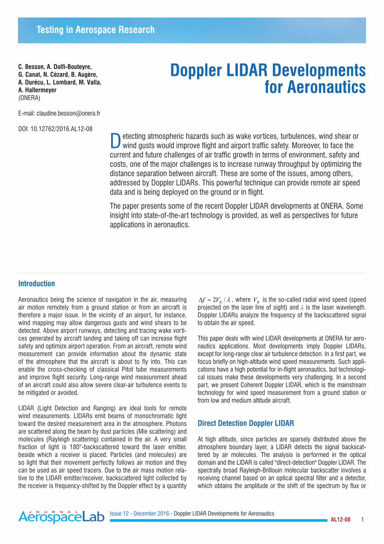
At high altitude, since particles are sparsely distributed above the atmosphere boundary layer, a LIDAR detects the signal backscat-tered by air molecules. The analysis is performed in the optical domain and the LIDAR is called "direct-detection" Doppler LIDAR. The spectrally broad Rayleigh-Brillouin molecular backscatter involves a receiving channel based on an optical spectral filter and a detector, which obtains the amplitude or the shift of the spectrum by flux or
Introduction
Aeronautics being the science of navigation in the air, measuring air motion remotely from a ground station or from an aircraft is therefore a major issue. In the vicinity of an airport, for instance, wind mapping may allow dangerous gusts and wind shears to be detected. Above airport runways, detecting and tracing wake vorti-ces generated by aircraft landing and taking off can increase flight safety and optimize airport operation. From an aircraft, remote wind measurement can provide information about the dynamic state of the atmosphere that the aircraft is about to fly into. This can enable the cross-checking of classical Pitot tube measurements and improve flight security. Long-range wind measurement ahead of an aircraft could also allow severe clear-air turbulence events to be mitigated or avoided.
LIDAR (Light Detection and Ranging) are ideal tools for remote wind measurements. LIDARs emit beams of monochromatic light toward the desired measurement area in the atmosphere. Photons are scattered along the beam by dust particles (Mie scattering) and molecules (Rayleigh scattering) contained in the air. A very small fraction of light is 180°-backscattered toward the laser emitter, beside which a receiver is placed. Particles (and molecules) are so light that their movement perfectly follows air motion and they can be used as air speed tracers. Due to the air mass motion rela-tive to the LIDAR emitter/receiver, backscattered light collected by the receiver is frequency-shifted by the Doppler effect by a quantity
Doppler LIDAR Developments for Aeronautics
C. Besson, A. Dolfi-Bouteyre, G. Canat, N. Cézard, B. Augère, A. Durécu, L. Lombard, M. Valla, A. Hallermeyer(ONERA)
E-mail: [email protected]
DOI: 10.12762/2016.AL12-08
Detecting atmospheric hazards such as wake vortices, turbulences, wind shear or wind gusts would improve flight and airport traffic safety. Moreover, to face the
current and future challenges of air traffic growth in terms of environment, safety and costs, one of the major challenges is to increase runway throughput by optimizing the distance separation between aircraft. These are some of the issues, among others, addressed by Doppler LIDARs. This powerful technique can provide remote air speed data and is being deployed on the ground or in flight.
The paper presents some of the recent Doppler LIDAR developments at ONERA. Some insight into state-of-the-art technology is provided, as well as perspectives for future applications in aeronautics.
Issue 12 - December 2016 - Doppler LIDAR Developments for Aeronautics AL12-08 2
fringe pattern analysis (see Figure 1). Such systems generally require medium linewidth (<1 GHz) monomode lasers emitting at small wavelengths (UV or visible), since the backscattered signal decreases as λ4 (λ being the LIDAR wavelength) [13].
For atmospheric science applications, Direct Detection Doppler LIDARs are used for studies in connection with climate issues, for example, aerosol transport characterization and stratosphere/tropo-sphere mixing layer observations. Such LIDARs have long been devel-oped by atmosphere science laboratories such as LATMOS, which was a pioneer of the technology in France (see for example [6][16][22]). Ground-based direct Detection Doppler LIDARs for high-altitude observations require high-power laser (>100 mJ/pulse), large tele-scopes (~1m). In France these systems are installed at the Obser-vatoire de Haute-Provence and the Observatoire du Maido (Reunion Island). These high-performance tools will soon be supplemented by a space-based Direct Detection Doppler LIDAR called ALADIN (Atmo-spheric Laser Doppler Instrument). ALADIN is the LIDAR payload of the ADM-Aeolus mission, a program launched 15 years ago by ESA. It will provide direct measurements of global wind fields from space. The purpose of the mission is to demonstrate improvements in numerical weather prediction and climate models. The LIDAR oper-ates in the UV (355 nm) [45]. The optical receiver combines a "Mie" channel (Fizeau interferometer analyzing winds from low-altitude aerosols and clouds) and a "Rayleigh" channel (double edge Fabry-Perot interferometer analyzing air molecules). The system is currently being qualified and should be launched in 2017.
In the field of aeronautics, airborne Direct Detection Doppler LIDARs are tested to evaluate the possibility of short-range turbulence detec-tion and mitigation. ONERA has built a short-range ground prototype demonstrating the feasibility of robust and daytime measurements with a Michelson fringe-imaging technique for Doppler analysis [14]. Similar developments have been made and promoted until their dem-onstration in flight throughout the EU project AWIATOR [48] [56], which used the Fabry-Perot fringe-imaging technique.
Another strong concern calling for Direct Detection LIDARs in aero-nautics is the long-range detection of clear air turbulences (CAT). Aircraft experience turbulence when they encounter a vertical airflow that varies on the horizontal length scales in the range of 30 m to 2 km for large commercial aircraft. Vertical airflow on these scales is associated with two distinct physical mechanisms: wave breaking caused by shear instabilities in clear air (Kelvin-Helmholtz instability) and convective updraughts and downdraughts in and around clouds and thunder storms. Clear-air turbulences are difficult to observe because of their relatively low occurrence. The physical phenom-enon has been, up to now, poorly understood and they are not well predicted. ONERA has been involved in two projects aimed at col-lecting and analyzing turbulence data: the MMEDTAC project [27] aimed at acquiring turbulence data with the LATMOS ground-based Rayleigh LIDAR located at the Observatoire de Haute-Provence. The DELICAT project involved a Rayleigh LIDAR assembled by the DLR/IPA, installed on board the NLR Citation aircraft for in-flight data acquisition [36]. Both of these projects were based on measur-ing the density fluctuations that are linked to strong vertical winds in atmospheric layers with high stability, rather than measuring the wind speed itself. It must be noted that, with this method, the atmosphere stability characterized by the Brunt-Väisälä frequency is assumed to be constant at the scale of measurement. The principle is to measure the amplitude fluctuations of the LIDAR signal due to a fluctuation in the molecule contribution to the backscattered signal. Particle contribution must thus be rejected, to avoid interference and spurious detections. Flying the system onboard adds extra complex-ity, since an agile filter is required to remove Mie scattering that is Doppler shifted by the varying aircraft speed. Particle signal rejection was performed by an optical filter based on polarization separation, which assumes that at the flight test altitude (30,000ft) particles are essentially polarizing ice crystals and ashes. CAT detection was con-sidered to be positive only in areas with a low-level particle signal. The estimation of relative fluctuations of the backscatter signal is assumed to not be modified in the presence of low-level particle scattering due to a well-mixed aerosol layer, the ratio between aero-sol and molecular backscattering remaining constant inside this layer. Although it was not possible to ensure that the atmosphere was totally free from aerosols, both projects enabled likely CAT data to be collected. New algorithms performing CAT retrieval have been developed for these two systems and will be used for future work on CAT characterization [28].
Rayleigh LIDAR involves cumbersome lasers and optics and complex key technology (e.g., agile filters), which explains why the technique is still at the level of demonstration for airborne sensors. Technology maturation is necessary to comply with aeronautics size and con-sumption constrains. However, since it relies on molecule scattering, Rayleigh LIDAR would be a reliable concept for operational sensors to detect atmospheric hazards at any altitude with reasonably easy certification procedures.
High power coherent Doppler LIDAR
Unlike direct detection LIDARs, coherent detection LIDAR rely solely on the presence of particles. Particles are dense in the lower atmo-sphere, i.e., from the ground up to a few kilometers, especially in the atmospheric boundary layer. At low altitudes, remote sensing of the air speed is also an important issue. Indeed, during land-ing and take-off, a minimal distance separation between aircraft is
air speed
Rayleigh spectrumν
νν
T ρ α
Mie spectrum
Laser
Optical spectrum analyzer
ur
Tρα
ru
Detected spectrum properties
•Central frequency (Doppler effect) air speed ur
•Rayleigh broadening temperature T•Rayleigh signal energy air density ρ•Mie signal energy mixing ratio α
Figure 1 – Direct detection Rayleigh-Mie LIDAR principle
Issue 12 - December 2016 - Doppler LIDAR Developments for Aeronautics AL12-08 3
necessary, in order to avoid the risk of encountering the wake vortex from a preceding aircraft. Wake vortices are two coherent counter-rotating flows created behind the aircraft wings and they induce a potentially dangerous rolling moment to the following aircraft. ICAO wake turbulence separation minima defined forty years ago are being redefined, in order to take into account airport traffic increase. Indeed, the strength and lifetime of wake vortices vary a lot with weather con-ditions. Their dissipation rate varies depending on the atmospheric turbulence level. They can also be transported out of the way towards incoming traffic by cross-winds. Other air disturbances, such as wind gusts or rapid change of the incoming wind direction, are also detri-mental to the airport traffic flow. Thus, anticipating these phenomena in the vicinity of airports is key information for air traffic optimization and safety.
Wake vortex locations and trajectories, wind turbulence level or wind maps can be used during certification or flight tests. They can be pro-vided by long range-range resolved Doppler LIDAR or Radar, which measure the wind speed with a high spatial resolution [31][54]. Such sensors have been evaluated for airport safety and re-categorization purposes within the framework of various projects, such as CREDOS, FIDELIO, SESAR or UFO [19][20][55].
Not only airport safety, but also flight tests of new air vehicles, manned or unmanned, could benefit from accurate knowledge of air dynamics disturbances in the vicinity of airports. Due to recent progress in fiber lasers and amplifiers, 1.5 µm fiber LIDAR technology is becoming a serious candidate for lightweight, compact, eye-safe airborne sys-tems. Demonstrators have been developed and flight-tested for new avionics or certification aids [3][51].
In this chapter, we review recent LIDAR achievements at ONERA and report on performance and field test results for two types of coherent Doppler LIDARs: ground based range resolved LIDAR and an airborne true air speed sensor.
In coherent detection LIDAR, the spectrally narrow Mie backscatter from aerosols and cloud particles is analyzed via the mixing of the backscattered signal and a reference wave (local oscillator) to pro-duce a radio frequency beat note, which can be temporally analyzed with a standard photodiode. The mixing also enhances the detection sensitivity, thanks to the optical product of the signal beam and the reference beam, and enables very low signal amplification. Compared to the direct detection LIDAR, the receiving channel of the coherent detection LIDAR is much simpler.
Although the technology has been used for decades, over the last ten years a renewed interest has arisen thanks to the availability of fiber components developed for the telecommunication market. Indeed, LIDAR based on fiber technology are low-cost and resilient to vibrat-ing environments. When emitting around 1.5 µm, they can benefit from telecom industry components with a large market at competi-tive costs and increased reliability. They offer simplified maintenance procedures compared to free-space technology and enable compact system designs. It is thus well suited to on-the-field operation for other domains besides aeronautics, such as defense, security or space [5][9][18].
Range-resolved wind LIDAR
Range resolution can be achieved with frequency modulation (FMCW) or pulsed emission. Whatever the technique, the fiber laser architec-ture based on a Master Oscillator Fiber Power Amplifier (MOFPA) offers the advantage of versatility: FMCW emission, pulse shape, duration, repetition rate and frequency characteristics can be varied from pulse to pulse at 100s of kHz rates. This unique "smart pulse" feature provides multifunction capability and perspectives for appli-cations, such as pilot aid, with simultaneous ranging and ground velocity measurement or anemometry and velocity, gas detection with multi-wavelength DIAL LIDAR (DIfferential Absorption LIDAR), simultaneous DIAL-Doppler LIDARs, etc.
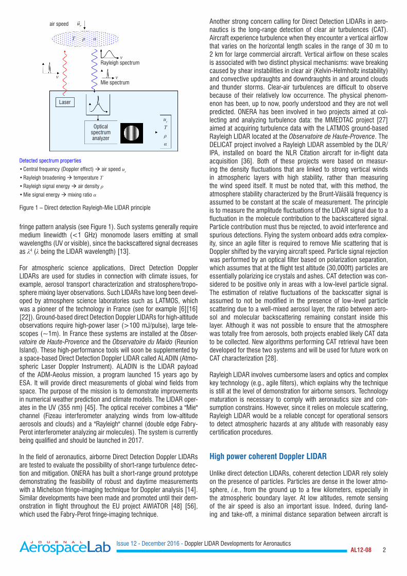
A typical coherent fiber LIDAR set up is depicted in Figure 2. The master oscillator is a continuous laser diode. Its output is split using a 50/50 fiber coupler. The transmitter channel goes through an acousto-optic modulator (AOM), which shapes the pulse and even-tually sets an intermediate frequency (IF). It is then amplified through a fiber pre-amplification stage and a filter (BPF) and a booster stage. At the output of the booster stage, the beam is polarized, quasi-single mode, and its temporal shape is optimized for efficient coherent detection. A passive fiber pigtail (1) is used to connect to the polarization beam splitter (PBS). The polarization beam splitter enables the transmitter channel and the receiver channel to circulate thanks to a quarter wave plate. Up to the beam splitter, all compo-nents are fibered. At that point, for high-peak-power emissions, a Brillouin effect may occur in fibers and free space optics are used (Paragraph 2 elaborates on the Brillouin effect). At the telescope output, the signal beam is emitted into the atmosphere boundary layer. The signal backscattered from natural aerosols is coupled to the fiber-beam splitter pigtail (2) and mixed with the local oscillator using a fiber coupler. The electric signal of the photodetector (DET)
1545 nm CW laser
Pulse generator
Preamp Booster
Sig. Processing
50/50
90/10
AOMPBS
12
Quarter waveplate Backscattering
aerosolsBPF
DET
Figure 2 – MOFPA coherent fiber LIDAR setup
Issue 12 - December 2016 - Doppler LIDAR Developments for Aeronautics AL12-08 4
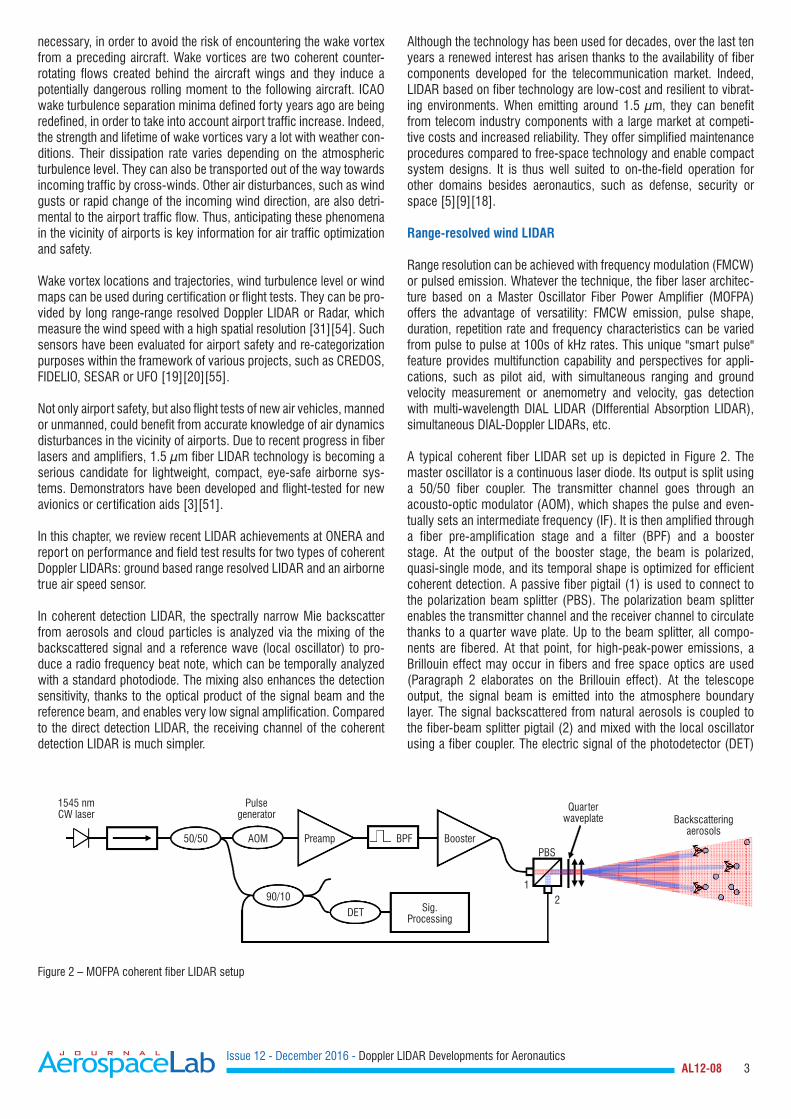
is digitized and processed in real time. The detected signal is split into temporal (or spatial) bins, which are Fourier transformed (see Figure 3). The maximum frequency of the spectrum fc is estimated with a suitable algorithm (maximum, centroid, etc.). Each bin is thus defined by its spatial coordinates and its central frequency enabling, for example, wind map reconstructions.
Most systems emit at around 1545 nm, which corresponds to high gain in erbium doped fibers and a good atmospheric transmission. The monostatic set-up (single pupil for transmitter and receiver chan-nels) sketched here is convenient for small-size scanning systems.
Wake vortex monitoring
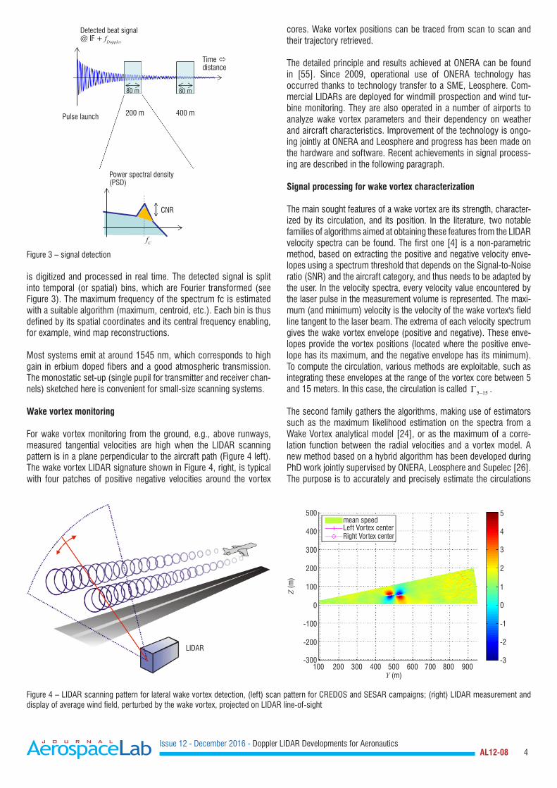
For wake vortex monitoring from the ground, e.g., above runways, measured tangential velocities are high when the LIDAR scanning pattern is in a plane perpendicular to the aircraft path (Figure 4 left). The wake vortex LIDAR signature shown in Figure 4, right, is typical with four patches of positive negative velocities around the vortex
cores. Wake vortex positions can be traced from scan to scan and their trajectory retrieved.
The detailed principle and results achieved at ONERA can be found in [55]. Since 2009, operational use of ONERA technology has occurred thanks to technology transfer to a SME, Leosphere. Com-mercial LIDARs are deployed for windmill prospection and wind tur-bine monitoring. They are also operated in a number of airports to analyze wake vortex parameters and their dependency on weather and aircraft characteristics. Improvement of the technology is ongo-ing jointly at ONERA and Leosphere and progress has been made on the hardware and software. Recent achievements in signal process-ing are described in the following paragraph.
Signal processing for wake vortex characterization
The main sought features of a wake vortex are its strength, character-ized by its circulation, and its position. In the literature, two notable families of algorithms aimed at obtaining these features from the LIDAR velocity spectra can be found. The first one [4] is a non-parametric method, based on extracting the positive and negative velocity enve-lopes using a spectrum threshold that depends on the Signal-to-Noise ratio (SNR) and the aircraft category, and thus needs to be adapted by the user. In the velocity spectra, every velocity value encountered by the laser pulse in the measurement volume is represented. The maxi-mum (and minimum) velocity is the velocity of the wake vortex's field line tangent to the laser beam. The extrema of each velocity spectrum gives the wake vortex envelope (positive and negative). These enve-lopes provide the vortex positions (located where the positive enve-lope has its maximum, and the negative envelope has its minimum). To compute the circulation, various methods are exploitable, such as integrating these envelopes at the range of the vortex core between 5 and 15 meters. In this case, the circulation is called 5 15−Γ .
The second family gathers the algorithms, making use of estimators such as the maximum likelihood estimation on the spectra from a Wake Vortex analytical model [24], or as the maximum of a corre-lation function between the radial velocities and a vortex model. A new method based on a hybrid algorithm has been developed during PhD work jointly supervised by ONERA, Leosphere and Supelec [26]. The purpose is to accurately and precisely estimate the circulations
Detected beat signal@ IF + fDoppler
Time distance
80 m
400 m200 mPulse launch
Power spectral density (PSD)
CNR
fC
80 m
Figure 3 – signal detection
LIDAR
500
400
300
200
100
0
-100
-200
-300100 200
mean speedLeft Vortex centerRight Vortex center
300 400 500Y (m)
Z (m
)
600
5
4
3
2
1
0
-1
-2
-3700 800 900
Figure 4 – LIDAR scanning pattern for lateral wake vortex detection, (left) scan pattern for CREDOS and SESAR campaigns; (right) LIDAR measurement and display of average wind field, perturbed by the wake vortex, projected on LIDAR line-of-sight
Issue 12 - December 2016 - Doppler LIDAR Developments for Aeronautics AL12-08 5
with a processing time as short as possible, so as to make this algo-rithm exploitable for operational projects. This is why a method has been set up to evaluate its precision and its robustness. The results of tests on simulated scenarios of different aircraft vortices and different weather conditions show that this algorithm is able to precisely locate wake vortices and to accurately estimate their circulation: the root mean square error is below 5%. In order to model the complex old vortex in the ground effect, large eddy simulations performed by UCL have been used. In this case, the error reaches 20%.
High spectral brilliance all fibered sources and SBS mitigation
The assets of fiber lasers are their high efficiency enabling a wall plug effi-ciency of 10% to 15%; their size – the volume of a coherent 2 W fiber laser is the size of a thick book – and their reliability due to spliced connectors.
ONERA has developed specific know-how in high-peak power, nar-row linewidth pulsed fiber lasers and amplifiers. The additional laser power provides increased coherent LIDAR capability in the range and scanning of large areas, as well as better system resistance to adverse weather conditions.
In order to reach long ranges within a short acquisition time, coher-ent wind LIDARs require high-power (~kW), narrow-linewidth (few MHz) pulsed laser sources with nearly Fourier transform lim-ited pulse duration (~1 µs). Eyesafe, all-fiber laser sources based on MOPFA (master oscillator, power fiber amplifier) architecture offer many advantages over bulk sources, such as low sensitivity to vibra-tions, efficiency and versatility. In the MOFPA coherent fiber LIDAR set up shown in Figure 2, the pulses are amplified in a sequence of fiber amplifier stages with increasing pump power and core size, which are separated by isolators and band-pass filters. MOFPA designers seek fibers with low numerical aperture (NA), which is favorable to single-mode guiding and low amplified spontaneous emission (ASE), in order to achieve high system efficiency.
Narrow linewidth pulsed MOPFA are usually limited in peak power by nonlinear effects arising in the fiber, such as Stimulated Brillouin Scattering (SBS) to a few 10s-100s Watts in standard fibers [7]. In standard single-mode fibers, the SBS threshold is reached when the peak power length product reaches about 80 W.m. The high-power density generates acoustic waves in the fiber core, which acts as a grating. The light transmitted by the fiber saturates, and part of this
light is backscattered by the grating. In fiber amplifiers, the backscat-tered light may be amplified in the active fiber generating high-peak-power backscattered pulses potentially harmful for upstream compo-nents [33].
The strength of the Brillouin nonlinearities in a fiber can be quantified by the intensity length product:
( ) ( )0
L
B effB
eff eff
P z dzg P L L
B gA A
= =∫
(1)
where gB is a Brillouin gain, L is the fiber length, Aeff is the effective area of the fundamental mode, ( )P z is the signal power distribution along the fiber, and Leff is the effective length. For a passive fiber the effective length is equal to the fiber length and for an active fiber the effective length depends on the fiber gain along the fiber [30]. From (1) it appears that there are three ways to act on the nonlinearities.
Increase in the mode area
The first way is to increase the fundamental mode effective area. Large-Mode-Area (LMA) fibers, with a large core diameter and low numerical aperture (NA) may be used to increase the mode area, but the fiber tends to guide higher-order transverse modes degrading the beam quality. A good spatial quality is crucial for many applications. For instance, in a coherent detection LIDAR when the beam quality factor M² equals 1.7 we expect the Carrier-to-Noise Ratio (CNR) to decrease by 3 dB [12]. The most efficient doped fibers today are based on the Erbium-Ytterbium codoping of phosphosilicate glasses. This composition has two important limitations. First, the core refrac-tive index is quite large and special pedestal structures are needed to reduce the NA to 0.09 and limit the proportion of higher-order trans-verse modes. A second limitation is that the core itself is usually inho-mogeous with a central dip in the refractive index profile resulting in a poor beam spatial quality.
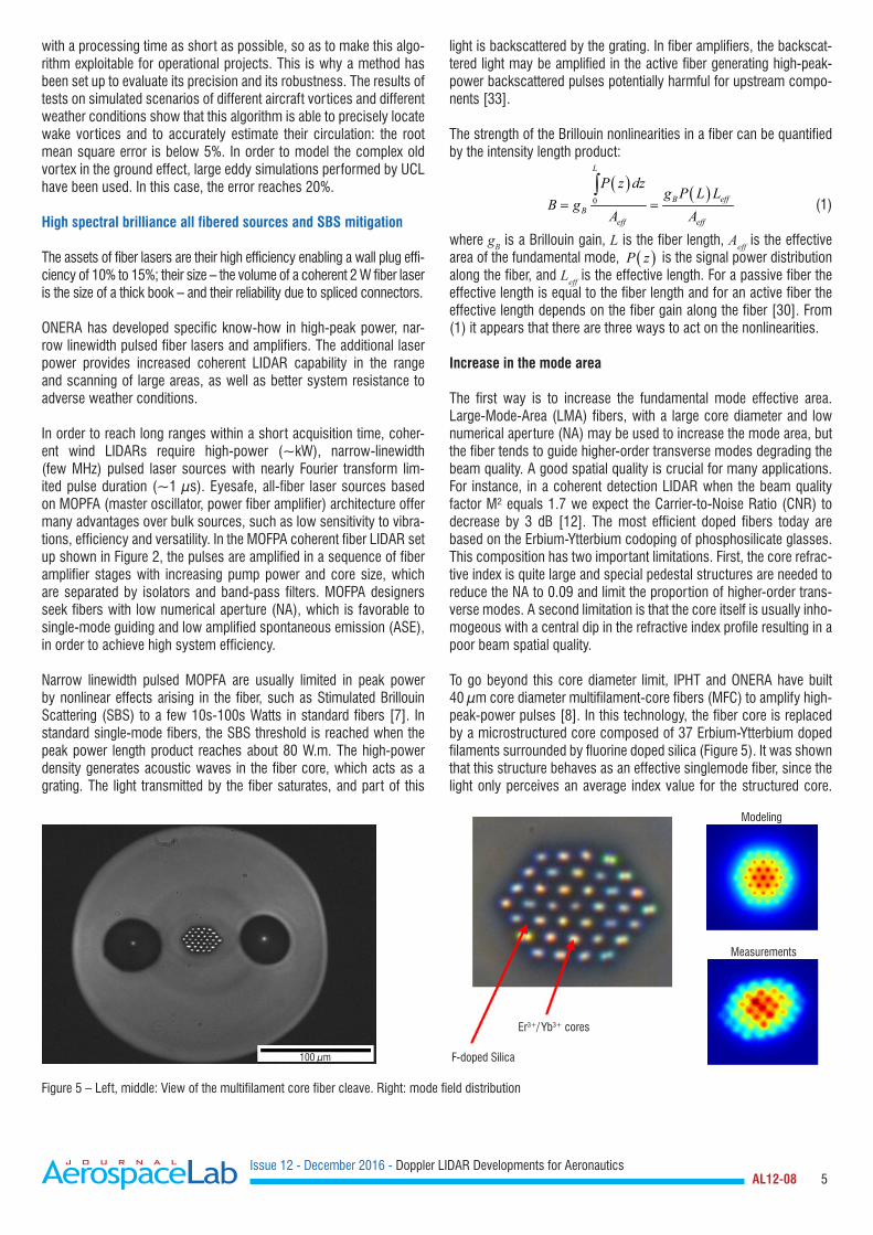
To go beyond this core diameter limit, IPHT and ONERA have built 40 µm core diameter multifilament-core fibers (MFC) to amplify high-peak-power pulses [8]. In this technology, the fiber core is replaced by a microstructured core composed of 37 Erbium-Ytterbium doped filaments surrounded by fluorine doped silica (Figure 5). It was shown that this structure behaves as an effective singlemode fiber, since the light only perceives an average index value for the structured core.
100 µm
Er3+/ Yb3+ cores
F-doped Silica
Modeling
Measurements
Figure 5 – Left, middle: View of the multifilament core fiber cleave. Right: mode field distribution
Issue 12 - December 2016 - Doppler LIDAR Developments for Aeronautics AL12-08 6
Pulses with 940 W peak power, 1 µs duration and 1 MHz laser linewidth were achieved. The beam quality is good with M²~1.3. However, this laser setup was not all-fiber and MFC fiber fabrication and integration in all-fiber lasers systems are challenging.
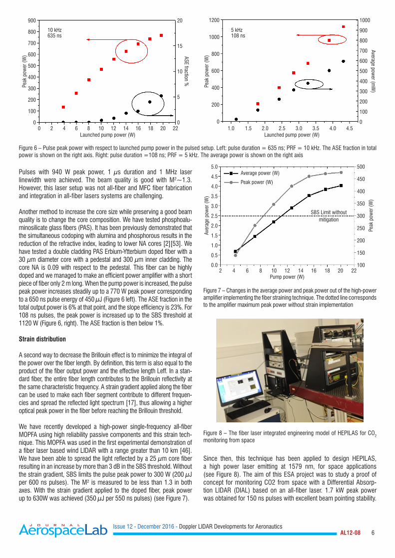
Another method to increase the core size while preserving a good beam quality is to change the core composition. We have tested phosphoalu-minosilicate glass fibers (PAS). It has been previously demonstrated that the simultaneous codoping with alumina and phosphorous results in the reduction of the refractive index, leading to lower NA cores [2][53]. We have tested a double cladding PAS Erbium-Ytterbium doped fiber with a 30 µm diameter core with a pedestal and 300 µm inner cladding. The core NA is 0.09 with respect to the pedestal. This fiber can be highly doped and we managed to make an efficient power amplifier with a short piece of fiber only 2 m long. When the pump power is increased, the pulse peak power increases steadily up to a 770 W peak power corresponding to a 650 ns pulse energy of 450 µJ (Figure 6 left). The ASE fraction in the total output power is 6% at that point, and the slope efficiency is 23%. For 108 ns pulses, the peak power is increased up to the SBS threshold at 1120 W (Figure 6, right). The ASE fraction is then below 1%.
Strain distribution
A second way to decrease the Brillouin effect is to minimize the integral of the power over the fiber length. By definition, this term is also equal to the product of the fiber output power and the effective length Leff. In a stan-dard fiber, the entire fiber length contributes to the Brillouin reflectivity at the same characteristic frequency. A strain gradient applied along the fiber can be used to make each fiber segment contribute to different frequen-cies and spread the reflected light spectrum [17], thus allowing a higher optical peak power in the fiber before reaching the Brillouin threshold.
We have recently developed a high-power single-frequency all-fiber MOPFA using high reliability passive components and this strain tech-nique. This MOPFA was used in the first experimental demonstration of a fiber laser based wind LIDAR with a range greater than 10 km [46]. We have been able to spread the light reflected by a 25 µm core fiber resulting in an increase by more than 3 dB in the SBS threshold. Without the strain gradient, SBS limits the pulse peak power to 300 W (200 µJ per 600 ns pulses). The M² is measured to be less than 1.3 in both axes. With the strain gradient applied to the doped fiber, peak power up to 630W was achieved (350 µJ per 550 ns pulses) (see Figure 7).
Since then, this technique has been applied to design HEPILAS, a high power laser emitting at 1579 nm, for space applications (see Figure 8). The aim of this ESA project was to study a proof of concept for monitoring CO2 from space with a Differential Absorp-tion LIDAR (DIAL) based on an all-fiber laser. 1.7 kW peak power was obtained for 150 ns pulses with excellent beam pointing stability.
900
800
700
600
500
400
300
200
100
0
20
15
10
5
0
10 kHz635 ns
0 2 4 6 8 10Launched pump power (W)
12 14 16 18 20 22
Peak
pow
er (W
) ASE fraction %
1000
900
800
700
600
500
400
300
200
100
0
1200
1000
800
600
400
200
0
Launched pump power (W)1.0 1.5 2.0 2.5 3.0 3.5 4.0 4.5
Average power (m
W)
Peak
pow
er (W
)
5 kHz108 ns
Figure 6 – Pulse peak power with respect to launched pump power in the pulsed setup. Left: pulse duration = 635 ns; PRF = 10 kHz. The ASE fraction in total power is shown on the right axis. Right: pulse duration =108 ns; PRF = 5 kHz. The average power is shown on the right axis
2 4 6 8 10 12Pump power (W)
14 16 18 20 22
Average power (W)
Peak power (W)
SBS Limit without mitigation
Aver
age
pow
er (W
)
Peak
pow
er (W
)
5.0
4.5
4.0
3.5
3.0
2.5
2.0
1.5
1.0
0.5
0.0
500
450
400
350
300
250
200
150
100
Figure 7 – Changes in the average power and peak power out of the high-power amplifier implementing the fiber straining technique. The dotted line corresponds to the amplifier maximum peak power without strain implementation
Figure 8 – The fiber laser integrated engineering model of HEPILAS for CO2 monitoring from space
Issue 12 - December 2016 - Doppler LIDAR Developments for Aeronautics AL12-08 7
A factor of 3 gain was obtained with a modest value of strain, thereby ensuring that the fiber lifetime was compatible with a 5 year duration space mission. The laser was also designed to withstand 10 kRad radiation, thanks to iXfiber radhard active fiber [10].
Coherent combination
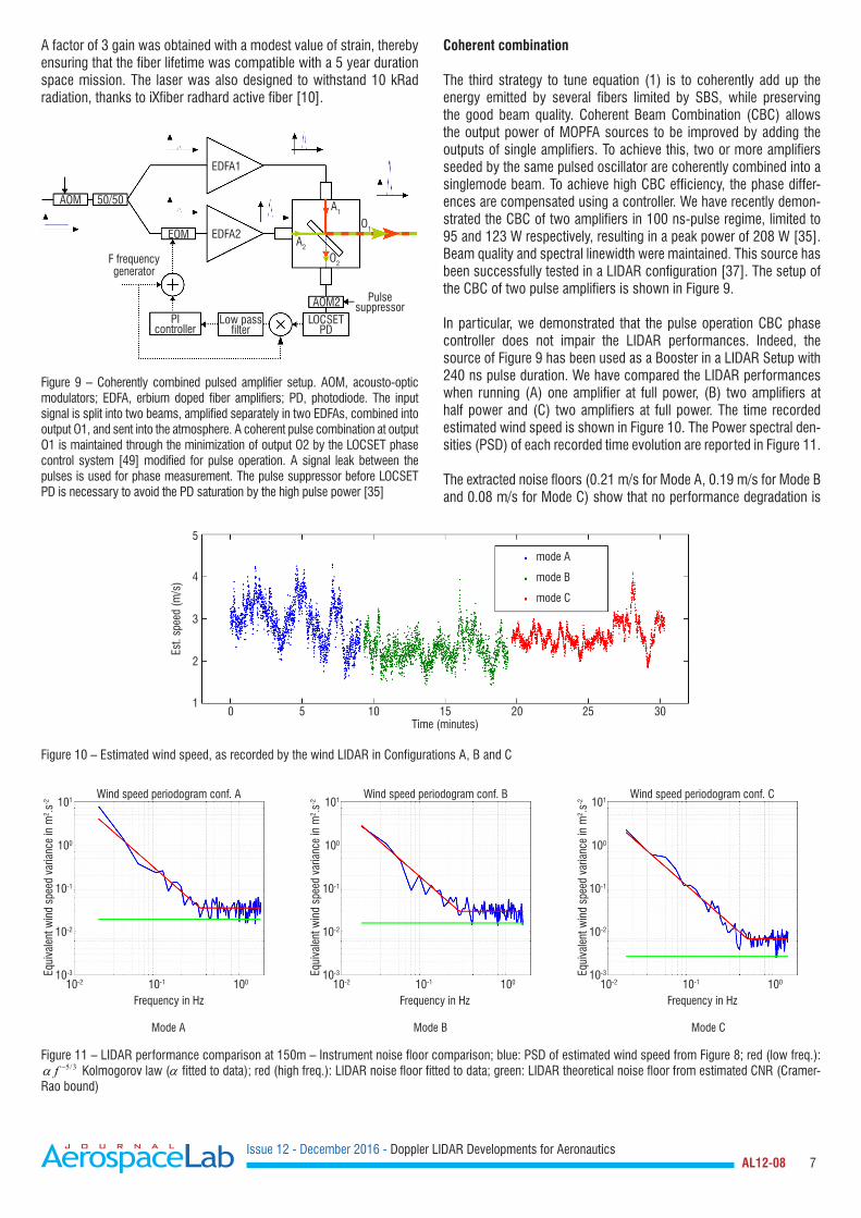
The third strategy to tune equation (1) is to coherently add up the energy emitted by several fibers limited by SBS, while preserving the good beam quality. Coherent Beam Combination (CBC) allows the output power of MOPFA sources to be improved by adding the outputs of single amplifiers. To achieve this, two or more amplifiers seeded by the same pulsed oscillator are coherently combined into a singlemode beam. To achieve high CBC efficiency, the phase differ-ences are compensated using a controller. We have recently demon-strated the CBC of two amplifiers in 100 ns-pulse regime, limited to 95 and 123 W respectively, resulting in a peak power of 208 W [35]. Beam quality and spectral linewidth were maintained. This source has been successfully tested in a LIDAR configuration [37]. The setup of the CBC of two pulse amplifiers is shown in Figure 9.
In particular, we demonstrated that the pulse operation CBC phase controller does not impair the LIDAR performances. Indeed, the source of Figure 9 has been used as a Booster in a LIDAR Setup with 240 ns pulse duration. We have compared the LIDAR performances when running (A) one amplifier at full power, (B) two amplifiers at half power and (C) two amplifiers at full power. The time recorded estimated wind speed is shown in Figure 10. The Power spectral den-sities (PSD) of each recorded time evolution are reported in Figure 11.
The extracted noise floors (0.21 m/s for Mode A, 0.19 m/s for Mode B and 0.08 m/s for Mode C) show that no performance degradation is
50/50AOM
EOM
AOM2 Pulse suppressor
O2
O1
A2
A1
EDFA1
EDFA2
F frequency generator
PI controller
Low pass filter
LOCSET PD
Figure 9 – Coherently combined pulsed amplifier setup. AOM, acousto-optic modulators; EDFA, erbium doped fiber amplifiers; PD, photodiode. The input signal is split into two beams, amplified separately in two EDFAs, combined into output O1, and sent into the atmosphere. A coherent pulse combination at output O1 is maintained through the minimization of output O2 by the LOCSET phase control system [49] modified for pulse operation. A signal leak between the pulses is used for phase measurement. The pulse suppressor before LOCSET PD is necessary to avoid the PD saturation by the high pulse power [35]
mode A
mode B
mode C
Time (minutes)
5
4
3
2
10 5 10 15 20 25 30
Est.
spee
d (m
/s)
Figure 10 – Estimated wind speed, as recorded by the wind LIDAR in Configurations A, B and C
Wind speed periodogram conf. A
Frequency in Hz
101
100
10-1
10-2
10-3
10-2 10-1 100
Equi
vale
nt w
ind
spee
d va
rianc
e in
m2 .s
-2
Frequency in Hz
101
100
10-1
10-2
10-2 10-1 10010-3Eq
uiva
lent
win
d sp
eed
varia
nce
in m
2 .s-2
Wind speed periodogram conf. B
Frequency in Hz
101
100
10-1
10-2
10-2 10-1 10010-3Eq
uiva
lent
win
d sp
eed
varia
nce
in m
2 .s-2
Wind speed periodogram conf. C
Mode A Mode B Mode C
Figure 11 – LIDAR performance comparison at 150m – Instrument noise floor comparison; blue: PSD of estimated wind speed from Figure 8; red (low freq.): 5/3fα − Kolmogorov law (α fitted to data); red (high freq.): LIDAR noise floor fitted to data; green: LIDAR theoretical noise floor from estimated CNR (Cramer-
Rao bound)
Issue 12 - December 2016 - Doppler LIDAR Developments for Aeronautics AL12-08 8
measured when using CBC. When both amplifiers are run at full power, the expected LIDAR performance improvement is reached. In all cases, the LIDAR performance is very close to its optimum value, given by the Cramer-Rao bound. These results show the compatibility of coher-ent beam combination with coherent wind LIDAR. Potentially, tens to hundreds of those amplifiers can be combined by this technique.
Long-range LIDAR measurements
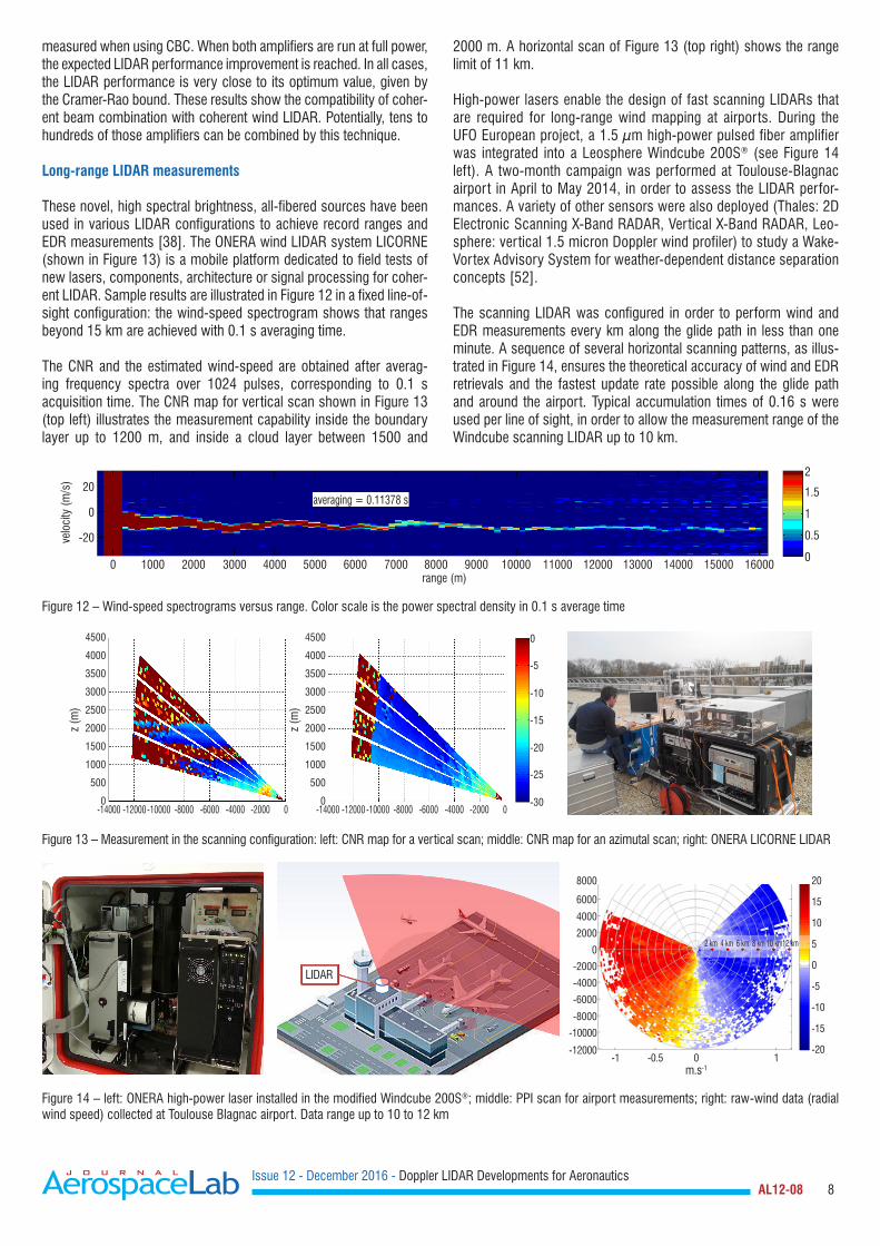
These novel, high spectral brightness, all-fibered sources have been used in various LIDAR configurations to achieve record ranges and EDR measurements [38]. The ONERA wind LIDAR system LICORNE (shown in Figure 13) is a mobile platform dedicated to field tests of new lasers, components, architecture or signal processing for coher-ent LIDAR. Sample results are illustrated in Figure 12 in a fixed line-of-sight configuration: the wind-speed spectrogram shows that ranges beyond 15 km are achieved with 0.1 s averaging time.
The CNR and the estimated wind-speed are obtained after averag-ing frequency spectra over 1024 pulses, corresponding to 0.1 s acquisition time. The CNR map for vertical scan shown in Figure 13 (top left) illustrates the measurement capability inside the boundary layer up to 1200 m, and inside a cloud layer between 1500 and
2000 m. A horizontal scan of Figure 13 (top right) shows the range limit of 11 km.
High-power lasers enable the design of fast scanning LIDARs that are required for long-range wind mapping at airports. During the UFO European project, a 1.5 µm high-power pulsed fiber amplifier was integrated into a Leosphere Windcube 200S® (see Figure 14 left). A two-month campaign was performed at Toulouse-Blagnac airport in April to May 2014, in order to assess the LIDAR perfor-mances. A variety of other sensors were also deployed (Thales: 2D Electronic Scanning X-Band RADAR, Vertical X-Band RADAR, Leo-sphere: vertical 1.5 micron Doppler wind profiler) to study a Wake-Vortex Advisory System for weather-dependent distance separation concepts [52].
The scanning LIDAR was configured in order to perform wind and EDR measurements every km along the glide path in less than one minute. A sequence of several horizontal scanning patterns, as illus-trated in Figure 14, ensures the theoretical accuracy of wind and EDR retrievals and the fastest update rate possible along the glide path and around the airport. Typical accumulation times of 0.16 s were used per line of sight, in order to allow the measurement range of the Windcube scanning LIDAR up to 10 km.
20
0
-20
0 1000 2000 3000 4000 5000 6000 7000 8000range (m)
averaging = 0.11378 s
velo
city
(m/s
)
9000 10000 11000 12000 13000 14000 15000 16000
2
1.5
1
0.5
0
Figure 12 – Wind-speed spectrograms versus range. Color scale is the power spectral density in 0.1 s average time
4500
4000
3500
3000
2500
2000
1500
1000
500
0
4500
4000
3500
3000
2500
2000
1500
1000
500
0
z (m
)
-14000 -14000-12000 -12000-10000 -10000-8000 -8000-6000 -6000-4000 -4000-2000 -20000 0
0
-5
-10
-15
-20
-25
-30
z (m
)
Figure 13 – Measurement in the scanning configuration: left: CNR map for a vertical scan; middle: CNR map for an azimutal scan; right: ONERA LICORNE LIDAR
LIDAR
8000
6000
4000
2000
0
-2000
-4000
-6000
-8000
-10000
-12000-1 -0.5 0
m.s-1
20
15
10
5
0
-5
-10
-15
-201
2 km 4 km 6 km 8 km 10 km12 km
Figure 14 – left: ONERA high-power laser installed in the modified Windcube 200S®; middle: PPI scan for airport measurements; right: raw-wind data (radial wind speed) collected at Toulouse Blagnac airport. Data range up to 10 to 12 km
Issue 12 - December 2016 - Doppler LIDAR Developments for Aeronautics AL12-08 9
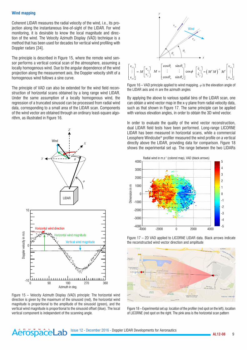
Wind mapping
Coherent LIDAR measures the radial velocity of the wind, i.e., its pro-jection along the instantaneous line-of-sight of the LIDAR. For wind monitoring, it is desirable to know the local magnitude and direc-tion of the wind. The Velocity Azimuth Display (VAD) technique is a method that has been used for decades for vertical wind profiling with Doppler radars [34].
The principle is described in Figure 15, where the remote wind sen-sor performs a vertical conical scan of the atmosphere, assuming a locally homogenous wind. Due to the angular dependence of the wind projection along the measurement axis, the Doppler velocity shift of a homogenous wind follows a sine curve. The principle of VAD can also be extended for the wind field recon-struction of horizontal scans obtained by a long range wind LIDAR. Under the same assumption of a locally homogenous wind, the regression of a truncated sinusoid can be processed from radial wind data, corresponding to a small area of the LIDAR scan. Components of the wind vector are obtained through an ordinary least-square algo-rithm, as illustrated in Figure 16.
By applying the above to various spatial bins of the LIDAR scan, one can obtain a wind vector map in the x-y plane from radial velocity data, such as that shown in Figure 17. The same principle can be applied with various elevation angles, in order to obtain the 3D wind vector.
In order to evaluate the quality of the wind vector reconstruction, dual LIDAR field tests have been performed. Long-range LICORNE LIDAR has been measured in horizontal scans, while a commercial Leosphere Windcube® profiler measured the wind profile on a vertical directly above the LIDAR, providing data for comparison. Figure 18 shows the experimental set up. The range between the two LIDARs
Z
X
θ
φ
Y
Wind
LIDAR
10
Horizontal wind direction
Horizontal wind magnitude
Vertical wind magnitude0
-100 90 180
Azimuth in deg.
Dopp
ler v
eloci
ty in
m/s
270 360
Figure 15 – Velocity Azimuth Display (VAD) principle: The horizontal wind direction is given by the maximum of the sinusoid (red), the horizontal wind magnitude is proportional to the amplitude of the sinusoid (green), and the vertical wind magnitude is proportional to the sinusoid offset (blue). The local vertical component is independent of the scanning angle.
y
xθn
θ1
vrn
vr1
Wind
( )1
1ˆˆ
rx t t
yrn
vv
M M Mv
v
−
=
1 1cos sincos
cos sinn n
Mθ θ
φθ θ
=
1rx
yrn
vv
Mv
v
=
Figure 16 – VAD principle applied to wind mapping. φ is the elevation angle of the LIDAR axis and θi are the azimuth angles
4000
3000
2000
1000
0
-1000
-2000
-3000
-4000
5
4
3
2
1
0
-1
-2
-3
-4
-5
Radial wind in m.s-1 (colored map), VAD (black arrows)
Dim
ensi
on in
m
-4000 -2000 2000 40000
Figure 17 – 2D VAD applied to LICORNE LIDAR data. Black arrows indicate the reconstructed wind vector direction and amplitude
Figure 18 – Experimental set up: location of the profiler (red spot on the left), location of LICORNE (red spot on the right. The pink area is the horizontal scan pattern
Issue 12 - December 2016 - Doppler LIDAR Developments for Aeronautics AL12-08 10
was 2100 meters. The LICORNE horizontal scan pattern covered +/-15°. Given the necessary elevation angle of 15° (in order to avoid trees around ONERA), the horizontal scan pattern was 540 meters above the wind profiler location.
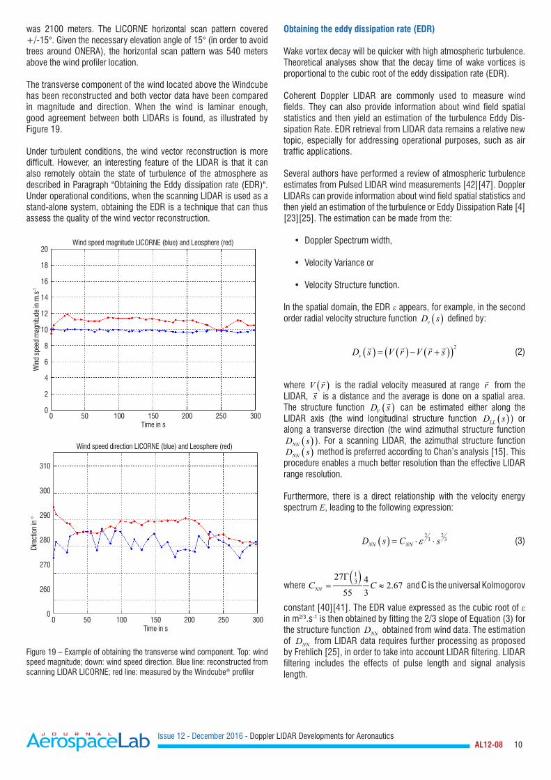
The transverse component of the wind located above the Windcube has been reconstructed and both vector data have been compared in magnitude and direction. When the wind is laminar enough, good agreement between both LIDARs is found, as illustrated by Figure 19.
Under turbulent conditions, the wind vector reconstruction is more difficult. However, an interesting feature of the LIDAR is that it can also remotely obtain the state of turbulence of the atmosphere as described in Paragraph "Obtaining the Eddy dissipation rate (EDR)". Under operational conditions, when the scanning LIDAR is used as a stand-alone system, obtaining the EDR is a technique that can thus assess the quality of the wind vector reconstruction.
Obtaining the eddy dissipation rate (EDR)
Wake vortex decay will be quicker with high atmospheric turbulence. Theoretical analyses show that the decay time of wake vortices is proportional to the cubic root of the eddy dissipation rate (EDR).
Coherent Doppler LIDAR are commonly used to measure wind fields. They can also provide information about wind field spatial statistics and then yield an estimation of the turbulence Eddy Dis-sipation Rate. EDR retrieval from LIDAR data remains a relative new topic, especially for addressing operational purposes, such as air traffic applications.
Several authors have performed a review of atmospheric turbulence estimates from Pulsed LIDAR wind measurements [42][47]. Doppler LIDARs can provide information about wind field spatial statistics and then yield an estimation of the turbulence or Eddy Dissipation Rate [4][23][25]. The estimation can be made from the:
• Doppler Spectrum width,
• Velocity Variance or
• Velocity Structure function.
In the spatial domain, the EDR ε appears, for example, in the second order radial velocity structure function ( )vD s defined by:
( ) ( ) ( )( )2vD s V r V r s= − +
(2)
where ( )V r is the radial velocity measured at range r from the LIDAR, s is a distance and the average is done on a spatial area. The structure function ( )VD s can be estimated either along the LIDAR axis (the wind longitudinal structure function ( )LLD s ) or along a transverse direction (the wind azimuthal structure function
( )NND s ). For a scanning LIDAR, the azimuthal structure function ( )NND s method is preferred according to Chan’s analysis [15]. This
procedure enables a much better resolution than the effective LIDAR range resolution.
Furthermore, there is a direct relationship with the velocity energy spectrum E, leading to the following expression:
( )2 2
3 3NN NND s C sε= ⋅ ⋅ (3)
where ( )1
327 4 2.67
55 3NNC CΓ
= ≈ and C is the universal Kolmogorov
constant [40][41]. The EDR value expressed as the cubic root of ε in m2/3.s-1 is then obtained by fitting the 2/3 slope of Equation (3) for the structure function ( )NND s obtained from wind data. The estimation of ( )NND s from LIDAR data requires further processing as proposed by Frehlich [25], in order to take into account LIDAR filtering. LIDAR filtering includes the effects of pulse length and signal analysis length.
20
18
16
14
12
10
8
6
4
2
0
Wind speed magnitude LICORNE (blue) and Leosphere (red)
Win
d sp
eed
mag
nitu
de in
m.s
-1
0 50 100 150Time in s
200 250 300
310
300
290
280
270
260
0
Dire
ctio
n in
°
0 50 100 150Time in s
200 250 300
Wind speed direction LICORNE (blue) and Leosphere (red)
Figure 19 – Example of obtaining the transverse wind component. Top: wind speed magnitude; down: wind speed direction. Blue line: reconstructed from scanning LIDAR LICORNE; red line: measured by the Windcube® profiler
Issue 12 - December 2016 - Doppler LIDAR Developments for Aeronautics AL12-08 11
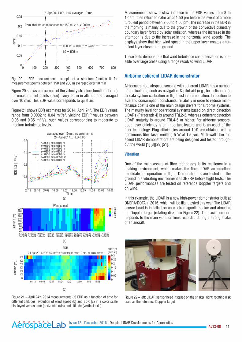
Figure 20 shows an example of the velocity structure function fit (red) for measurement points (blue) every 50 m in altitude and averaged over 10 min. This EDR value corresponds to quiet air.
Figure 21 shows EDR estimates for 2014, April 24th. The EDR values range from 0.0002 to 0.04 m-2/s3, yielding EDR1/3 values between 0.06 and 0.35 m-2/3/s, such values corresponding to moderate to medium turbulence levels.
Measurements show a slow increase in the EDR values from 8 to 12 am, then return to calm air at 1:50 pm before the event of a more turbulent period between 2:00 to 4:00 pm. The increase in the EDR in the morning is mainly due to the growth of the convective planetary boundary layer forced by solar radiation, whereas the increase in the afternoon is due to the increase in the horizontal wind speeds. The displays show that high wind speed in the upper layer creates a tur-bulent layer close to the ground.
These tests demonstrate that wind turbulence characterization is pos-sible over large areas using a range resolved wind LIDAR.
Airborne coherent LIDAR demonstrator
Airborne remote airspeed sensing with coherent LIDAR has a number of applications, such as navigation & pilot aid (e.g., for helicopters), air data system calibration or flight test instrumentation. In addition to size and consumption constraints, reliability in order to reduce main-tenance cost is one of the main design drivers for airborne systems. The maturity level for operational systems based on direct detection LIDARs (Paragraph 4) is around TRL2-3, whereas coherent detection LIDAR maturity is around TRL4-5 or higher. For airborne sensors, good laser efficiency is an important feature and is an asset of the fiber technology. Plug efficiencies around 10% are obtained with a continuous fiber laser emitting 5 W at 1.5 µm. Multi-watt fiber air-speed LIDAR demonstrators are being designed and tested through-out the world [1][3][29][51].
Vibration
One of the main assets of fiber technology is its resilience in a shaking environment, which makes the fiber LIDAR an excellent candidate for operation in flight. Demonstrators are tested on the ground in a vibrating environment at ONERA before flight tests. The LIDAR performances are tested on reference Doppler targets and on wind.
In this example, the LIDAR is a new high-power demonstrator built at ONERA/DOTA in 2016, which will be flight tested this year. The LIDAR sensor head is installed on an electromagnetic shaker and aimed at the Doppler target (rotating disk, see Figure 22). The excitation cor-responds to the main vibration lines recorded during a strong shake of an aircraft.
0.25
Azimuthal structure fonction for 150 m < h < 200m
EDR 1/3 = 0.0476 m 2/3.s-1
L0 = 505 m
15-Apr-2014 09:14:47 averaged 10 mn
0.2
0.15
0.1
0.05
00 100 200 300 400
m
m²/s
²
500 600 700 800
Fig. 20 – EDR measurement: example of a structure function fit for measurement points between 150 and 200 m averaged over 10 min
z=0050 m to 0100 mz=0100 m to 0150 mz=0150 m to 0200 mz=0200 m to 0250 mz=0250 m to 0300 mz=0300 m to 03500 mz=0350 m to 0400 m
0.4
0.3
0.2
0.1
007:12 08:10 09:09 10:08 11:07
Time12:06 13:05 14:04 15:03 16:02
averaged over 10 mn, no error terms24-Apr-2014... : EDR 1/3
EDR
1/3
(m2/
3 .s-1)
(a)
Wind speed220200180160140120100806040
-12-10-8-6-4-2-0
Wind speed
08:00:0014/04/24
07:00:0014/04/24
09:00:0014/04/24
10:00:0014/04/24
11:00:0014/04/24
12:00:0014/04/24
13:00:0014/04/24
14:00:0014/04/24
15:00:0014/04/24
16:00:0014/04/24
altit
ude
(m)
(b)
35030025020015010050
0.30.250.20.150.10.050
08:12 09:09 10:07 11:04 12:01 12:59 13:56 14:53
EDR 1/3(m2/3.s-1)
altit
ude
(m)
EDR
24-Apr-2014. EDR 1/3 (m2/3.s-1) averaged over 10 mn. no error terms
(c)
Figure 21 – April 24th, 2014 measurements.(a) EDR as a function of time for different altitudes; evolution of wind speed (b) and EDR (c) in a color scale displayed versus time (horizontal axis) and altitude (vertical axis)
Figure 22 – left: LIDAR sensor head installed on the shaker; right: rotating disk used as the reference Doppler target
Issue 12 - December 2016 - Doppler LIDAR Developments for Aeronautics AL12-08 12
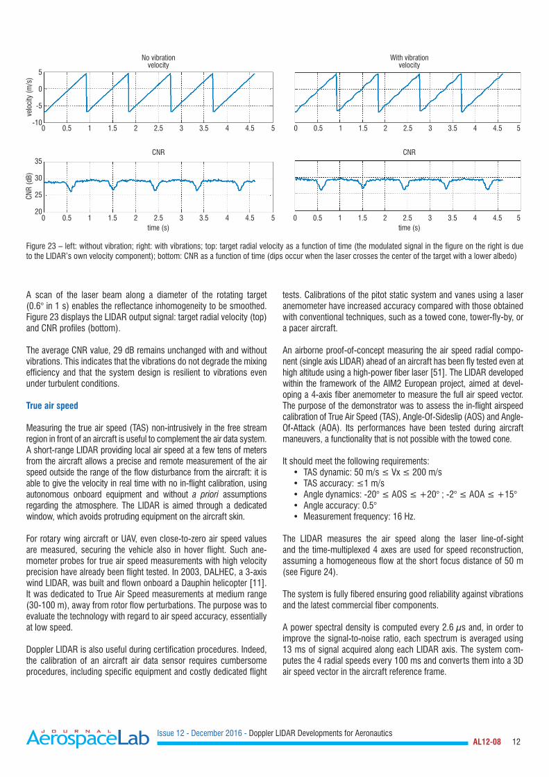
A scan of the laser beam along a diameter of the rotating target (0.6° in 1 s) enables the reflectance inhomogeneity to be smoothed. Figure 23 displays the LIDAR output signal: target radial velocity (top) and CNR profiles (bottom).
The average CNR value, 29 dB remains unchanged with and without vibrations. This indicates that the vibrations do not degrade the mixing efficiency and that the system design is resilient to vibrations even under turbulent conditions.
True air speed
Measuring the true air speed (TAS) non-intrusively in the free stream region in front of an aircraft is useful to complement the air data system. A short-range LIDAR providing local air speed at a few tens of meters from the aircraft allows a precise and remote measurement of the air speed outside the range of the flow disturbance from the aircraft: it is able to give the velocity in real time with no in-flight calibration, using autonomous onboard equipment and without a priori assumptions regarding the atmosphere. The LIDAR is aimed through a dedicated window, which avoids protruding equipment on the aircraft skin.
For rotary wing aircraft or UAV, even close-to-zero air speed values are measured, securing the vehicle also in hover flight. Such ane-mometer probes for true air speed measurements with high velocity precision have already been flight tested. In 2003, DALHEC, a 3-axis wind LIDAR, was built and flown onboard a Dauphin helicopter [11]. It was dedicated to True Air Speed measurements at medium range (30-100 m), away from rotor flow perturbations. The purpose was to evaluate the technology with regard to air speed accuracy, essentially at low speed.
Doppler LIDAR is also useful during certification procedures. Indeed, the calibration of an aircraft air data sensor requires cumbersome procedures, including specific equipment and costly dedicated flight
tests. Calibrations of the pitot static system and vanes using a laser anemometer have increased accuracy compared with those obtained with conventional techniques, such as a towed cone, tower-fly-by, or a pacer aircraft.
An airborne proof-of-concept measuring the air speed radial compo-nent (single axis LIDAR) ahead of an aircraft has been fly tested even at high altitude using a high-power fiber laser [51]. The LIDAR developed within the framework of the AIM2 European project, aimed at devel-oping a 4-axis fiber anemometer to measure the full air speed vector. The purpose of the demonstrator was to assess the in-flight airspeed calibration of True Air Speed (TAS), Angle-Of-Sideslip (AOS) and Angle-Of-Attack (AOA). Its performances have been tested during aircraft maneuvers, a functionality that is not possible with the towed cone.
It should meet the following requirements: • TASdynamic:50m/s≤Vx≤200m/s• TASaccuracy:≤1m/s• Angledynamics:-20°≤AOS≤+20°;-2°≤AOA≤+15°• Angle accuracy: 0.5°• Measurement frequency: 16 Hz.
The LIDAR measures the air speed along the laser line-of-sight and the time-multiplexed 4 axes are used for speed reconstruction, assuming a homogeneous flow at the short focus distance of 50 m (see Figure 24).
The system is fully fibered ensuring good reliability against vibrations and the latest commercial fiber components.
A power spectral density is computed every 2.6 µs and, in order to improve the signal-to-noise ratio, each spectrum is averaged using 13 ms of signal acquired along each LIDAR axis. The system com-putes the 4 radial speeds every 100 ms and converts them into a 3D air speed vector in the aircraft reference frame.
No vibrationvelocity
velo
city
(m/s
)
0 0
0 0
0.5 0.5
0.5 0.5
1 1
1 1
1.5 1.5
1.5 1.5
2 2
2 2
2.5 2.5
2.5 2.5
3 3
3 3
3.5 3.5
3.5 3.5
4 4
4 4
4.5 4.5
4.5 4.5
5 5
5 5
CNR
(dB)
5
0
-5
-10
35
30
25
20
CNR
time (s)
With vibrationvelocity
CNR
time (s)
Figure 23 – left: without vibration; right: with vibrations; top: target radial velocity as a function of time (the modulated signal in the figure on the right is due to the LIDAR’s own velocity component); bottom: CNR as a function of time (dips occur when the laser crosses the center of the target with a lower albedo)
Issue 12 - December 2016 - Doppler LIDAR Developments for Aeronautics AL12-08 13
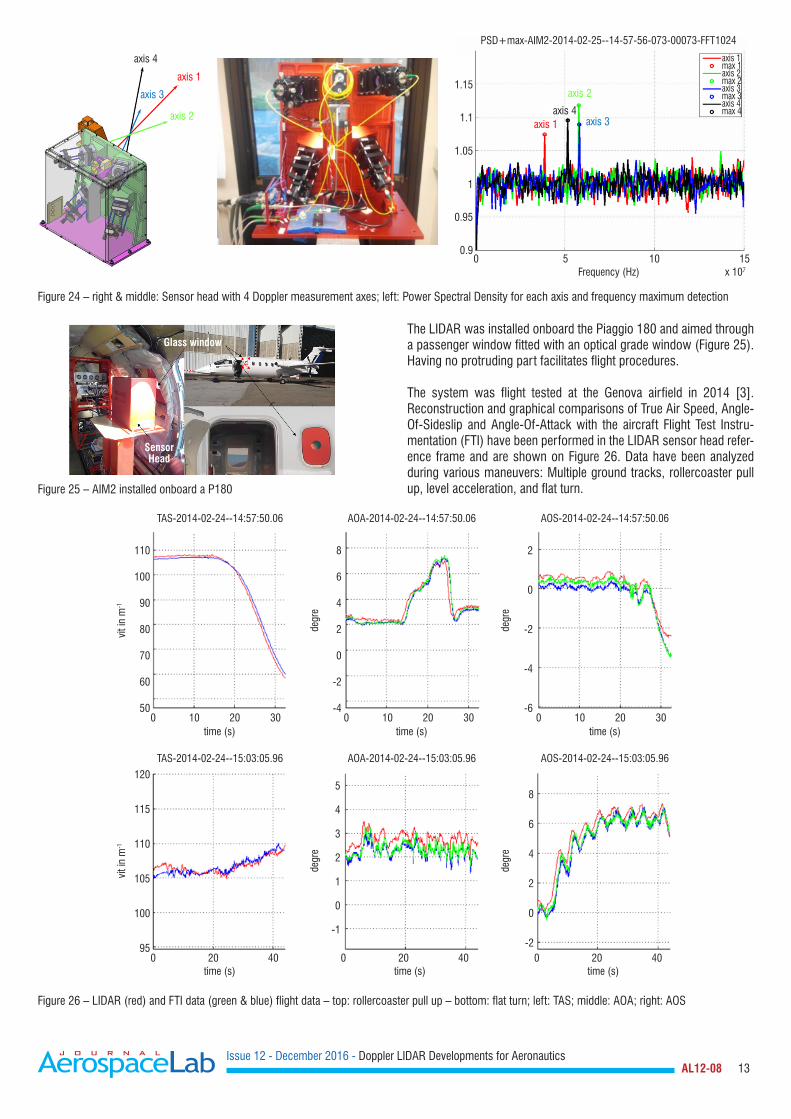
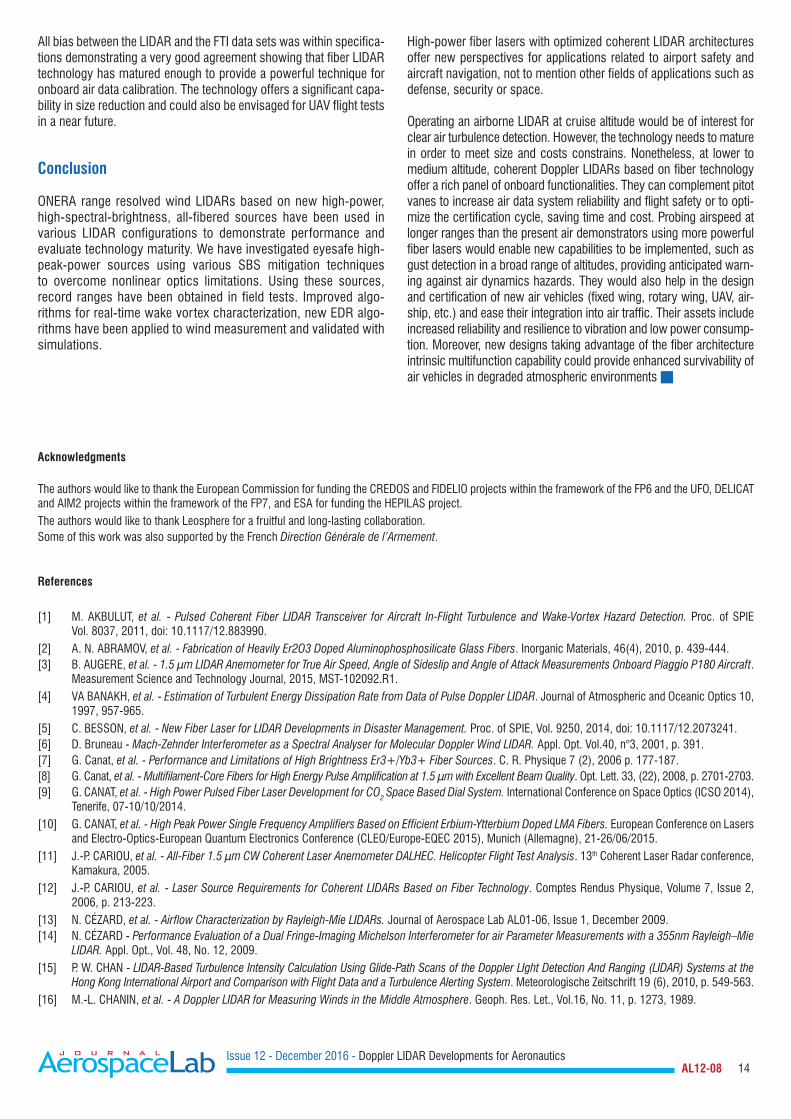
The LIDAR was installed onboard the Piaggio 180 and aimed through a passenger window fitted with an optical grade window (Figure 25). Having no protruding part facilitates flight procedures.
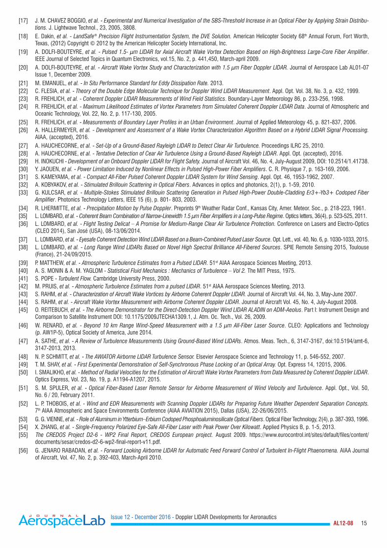
The system was flight tested at the Genova airfield in 2014 [3]. Reconstruction and graphical comparisons of True Air Speed, Angle-Of-Sideslip and Angle-Of-Attack with the aircraft Flight Test Instru-mentation (FTI) have been performed in the LIDAR sensor head refer-ence frame and are shown on Figure 26. Data have been analyzed during various maneuvers: Multiple ground tracks, rollercoaster pull up, level acceleration, and flat turn.
Glass window
Sensor Head
Figure 25 – AIM2 installed onboard a P180
axis 4
axis 1
axis 3
axis 2
axis 4axis 1 axis 3
axis 2
PSD+max-AIM2-2014-02-25--14-57-56-073-00073-FFT1024
1.15
1.1
1.05
1
0.95
0.90 5
Frequency (Hz) x 107
10 15
axis 1
axis 2
axis 3
axis 4
max 1
max 2
max 3
max 4
Figure 24 – right & middle: Sensor head with 4 Doppler measurement axes; left: Power Spectral Density for each axis and frequency maximum detection
TAS-2014-02-24--14:57:50.06
110
100
90
80
70
60
50
8
6
4
2
0
-2
-4
2
0
-2
-4
-60 0 010
vit i
n m
-1
time (s) time (s) time (s)
degr
e
degr
e
10 1020 20 2030 30 30
AOA-2014-02-24--14:57:50.06 AOS-2014-02-24--14:57:50.06
120
115
110
105
100
95
5
4
3
2
1
0
-1
8
6
4
2
0
-20 0 020 20 2040 40 40
vit i
n m
-1
time (s) time (s) time (s)
degr
e
degr
e
TAS-2014-02-24--15:03:05.96 AOA-2014-02-24--15:03:05.96 AOS-2014-02-24--15:03:05.96
Figure 26 – LIDAR (red) and FTI data (green & blue) flight data – top: rollercoaster pull up – bottom: flat turn; left: TAS; middle: AOA; right: AOS
Issue 12 - December 2016 - Doppler LIDAR Developments for Aeronautics AL12-08 14
All bias between the LIDAR and the FTI data sets was within specifica-tions demonstrating a very good agreement showing that fiber LIDAR technology has matured enough to provide a powerful technique for onboard air data calibration. The technology offers a significant capa-bility in size reduction and could also be envisaged for UAV flight tests in a near future.
Conclusion
ONERA range resolved wind LIDARs based on new high-power, high-spectral-brightness, all-fibered sources have been used in various LIDAR configurations to demonstrate performance and evaluate technology maturity. We have investigated eyesafe high-peak-power sources using various SBS mitigation techniques to overcome nonlinear optics limitations. Using these sources, record ranges have been obtained in field tests. Improved algo-rithms for real-time wake vortex characterization, new EDR algo-rithms have been applied to wind measurement and validated with simulations.
High-power fiber lasers with optimized coherent LIDAR architectures offer new perspectives for applications related to airport safety and aircraft navigation, not to mention other fields of applications such as defense, security or space.
Operating an airborne LIDAR at cruise altitude would be of interest for clear air turbulence detection. However, the technology needs to mature in order to meet size and costs constrains. Nonetheless, at lower to medium altitude, coherent Doppler LIDARs based on fiber technology offer a rich panel of onboard functionalities. They can complement pitot vanes to increase air data system reliability and flight safety or to opti-mize the certification cycle, saving time and cost. Probing airspeed at longer ranges than the present air demonstrators using more powerful fiber lasers would enable new capabilities to be implemented, such as gust detection in a broad range of altitudes, providing anticipated warn-ing against air dynamics hazards. They would also help in the design and certification of new air vehicles (fixed wing, rotary wing, UAV, air-ship, etc.) and ease their integration into air traffic. Their assets include increased reliability and resilience to vibration and low power consump-tion. Moreover, new designs taking advantage of the fiber architecture intrinsic multifunction capability could provide enhanced survivability of air vehicles in degraded atmospheric environments
Acknowledgments
The authors would like to thank the European Commission for funding the CREDOS and FIDELIO projects within the framework of the FP6 and the UFO, DELICAT and AIM2 projects within the framework of the FP7, and ESA for funding the HEPILAS project.The authors would like to thank Leosphere for a fruitful and long-lasting collaboration. Some of this work was also supported by the French Direction Générale de l’Armement.
References
[1] M. AKBULUT, et al. - Pulsed Coherent Fiber LIDAR Transceiver for Aircraft In-Flight Turbulence and Wake-Vortex Hazard Detection. Proc. of SPIE Vol. 8037, 2011, doi: 10.1117/12.883990.
[2] A. N. ABRAMOV, et al. - Fabrication of Heavily Er2O3 Doped Aluminophosphosilicate Glass Fibers. Inorganic Materials, 46(4), 2010, p. 439-444. [3] B. AUGERE, et al. - 1.5 µm LIDAR Anemometer for True Air Speed, Angle of Sideslip and Angle of Attack Measurements Onboard Piaggio P180 Aircraft.
Measurement Science and Technology Journal, 2015, MST-102092.R1.[4] VA BANAKH, et al. - Estimation of Turbulent Energy Dissipation Rate from Data of Pulse Doppler LIDAR. Journal of Atmospheric and Oceanic Optics 10,
1997, 957-965.[5] C. BESSON, et al. - New Fiber Laser for LIDAR Developments in Disaster Management. Proc. of SPIE, Vol. 9250, 2014, doi: 10.1117/12.2073241.[6] D. Bruneau - Mach-Zehnder Interferometer as a Spectral Analyser for Molecular Doppler Wind LIDAR. Appl. Opt. Vol.40, n°3, 2001, p. 391.[7] G. Canat, et al. - Performance and Limitations of High Brightness Er3+/Yb3+ Fiber Sources. C. R. Physique 7 (2), 2006 p. 177-187.[8] G. Canat, et al. - Multifilament-Core Fibers for High Energy Pulse Amplification at 1.5 µm with Excellent Beam Quality. Opt. Lett. 33, (22), 2008, p. 2701-2703.[9] G. CANAT, et al. - High Power Pulsed Fiber Laser Development for CO2 Space Based Dial System. International Conference on Space Optics (ICSO 2014),
Tenerife, 07-10/10/2014.[10] G. CANAT, et al. - High Peak Power Single Frequency Amplifiers Based on Efficient Erbium-Ytterbium Doped LMA Fibers. European Conference on Lasers
and Electro-Optics-European Quantum Electronics Conference (CLEO/Europe-EQEC 2015), Munich (Allemagne), 21-26/06/2015.[11] J.-P. CARIOU, et al. - All-Fiber 1.5 µm CW Coherent Laser Anemometer DALHEC. Helicopter Flight Test Analysis. 13th Coherent Laser Radar conference,
Kamakura, 2005.[12] J.-P. CARIOU, et al. - Laser Source Requirements for Coherent LIDARs Based on Fiber Technology. Comptes Rendus Physique, Volume 7, Issue 2,
2006, p. 213-223.[13] N. CézARD, et al. - Airflow Characterization by Rayleigh-Mie LIDARs. Journal of Aerospace Lab AL01-06, Issue 1, December 2009.[14] N. CézARD - Performance Evaluation of a Dual Fringe-Imaging Michelson Interferometer for air Parameter Measurements with a 355nm Rayleigh–Mie
LIDAR. Appl. Opt., Vol. 48, No. 12, 2009.[15] P. W. CHAN - LIDAR-Based Turbulence Intensity Calculation Using Glide-Path Scans of the Doppler LIght Detection And Ranging (LIDAR) Systems at the
Hong Kong International Airport and Comparison with Flight Data and a Turbulence Alerting System. Meteorologische zeitschrift 19 (6), 2010, p. 549-563.[16] M.-L. CHANIN, et al. - A Doppler LIDAR for Measuring Winds in the Middle Atmosphere. Geoph. Res. Let., Vol.16, No. 11, p. 1273, 1989.
Issue 12 - December 2016 - Doppler LIDAR Developments for Aeronautics AL12-08 15
[17] J. M. CHAVEz BOGGIO, et al. - Experimental and Numerical Investigation of the SBS-Threshold Increase in an Optical Fiber by Applying Strain Distribu-tions. J. Lightwave Technol., 23, 2005, 3808.
[18] E. Dakin, et al. - LandSafe® Precision Flight Instrumentation System, the DVE Solution. American Helicopter Society 68th Annual Forum, Fort Worth, Texas, (2012) Copyright © 2012 by the American Helicopter Society International, Inc.
[19] A. DOLFI-BOUTEYRE, et al. - Pulsed 1.5- µm LIDAR for Axial Aircraft Wake Vortex Detection Based on High-Brightness Large-Core Fiber Amplifier. IEEE Journal of Selected Topics in Quantum Electronics, vol.15, No. 2, p. 441,450, March-april 2009.
[20] A. DOLFI-BOUTEYRE, et al. - Aircraft Wake Vortex Study and Characterization with 1.5 µm Fiber Doppler LIDAR. Journal of Aerospace Lab AL01-07 Issue 1, December 2009.
[21] M. EMANUEL, et al. - In Situ Performance Standard for Eddy Dissipation Rate. 2013.[22] C. FLESIA, et al. - Theory of the Double Edge Molecular Technique for Doppler Wind LIDAR Measurement. Appl. Opt. Vol. 38, No. 3, p. 432, 1999.[23] R. FREHLICH, et al. - Coherent Doppler LIDAR Measurements of Wind Field Statistics. Boundary-Layer Meteorology 86, p. 233-256, 1998.[24] R. FREHLICH, et al. - Maximum Likelihood Estimates of Vortex Parameters from Simulated Coherent Doppler LIDAR Data. Journal of Atmospheric and
Oceanic Technology, Vol. 22, No. 2, p. 117-130, 2005.[25] R. FREHLICH, et al. - Measurements of Boundary Layer Profiles in an Urban Environment. Journal of Applied Meteorology 45, p. 821-837, 2006.[26] A. HALLERMEYER, et al. - Development and Assessment of a Wake Vortex Characterization Algorithm Based on a Hybrid LIDAR Signal Processing.
AIAA, (accepted), 2016.[27] A. HAUCHECORNE, et al. - Set-Up of a Ground-Based Rayleigh LIDAR to Detect Clear Air Turbulence. Proceedings ILRC 25, 2010.[28] A. HAUCHECORNE, et al. - Tentative Detection of Cear Air Turbulence Using a Ground-Based Rayleigh LIDAR. Appl. Opt. (accepted), 2016.[29] H. INOKUCHI - Development of an Onboard Doppler LIDAR for Flight Safety. Journal of Aircraft Vol. 46, No. 4, July-August 2009, DOI: 10.2514/1.41738.[30] Y. JAOUEN, et al. - Power Limitation Induced by Nonlinear Effects in Pulsed High-Power Fiber Amplifiers. C. R. Physique 7, p. 163-169, 2006.[31] S. KAMEYAMA, et al. - Compact All-Fiber Pulsed Coherent Doppler LIDAR System for Wind Sensing. Appl. Opt. 46, 1953-1962, 2007.[32] A. KOBYAKOV, et al. - Stimulated Brillouin Scattering in Optical Fibers. Advances in optics and photonics, 2(1), p. 1-59, 2010.[33] G. KULCSAR, et al. - Multiple-Stokes Stimulated Brillouin Scattering Generation in Pulsed High-Power Double-Cladding Er3+-Yb3+ Codoped Fiber
Amplifier. Photonics Technology Letters, IEEE 15 (6), p. 801- 803, 2003.[34] R. LHERMITTE, et al. - Precipitation Motion by Pulse Doppler. Preprints 9th Weather Radar Conf., Kansas City, Amer. Meteor. Soc., p. 218-223, 1961.[35] L. LOMBARD, et al. - Coherent Beam Combination of Narrow-Linewidth 1.5 µm Fiber Amplifiers in a Long-Pulse Regime. Optics letters, 36(4), p. 523-525, 2011.[36] L. LOMBARD, et al. - Flight Testing Delicat – A Promise for Medium-Range Clear Air Turbulence Protection. Conference on Lasers and Electro-Optics
(CLEO 2014), San José (USA), 08-13/06/2014.[37] L. LOMBARD, et al. - Eyesafe Coherent Detection Wind LIDAR Based on a Beam-Combined Pulsed Laser Source. Opt. Lett., vol. 40, No. 6, p. 1030-1033, 2015.[38] L. LOMBARD, et al. - Long Range Wind LIDARs Based on Novel High Spectral Brilliance All-Fibered Sources. SPIE Remote Sensing 2015, Toulouse
(France), 21-24/09/2015.[39] P. MATTHEW, et al. - Atmospheric Turbulence Estimates from a Pulsed LIDAR. 51st AIAA Aerospace Sciences Meeting, 2013.[40] A. S. MONIN & A. M. YAGLOM - Statistical Fluid Mechanics : Mechanics of Turbulence – Vol 2. The MIT Press, 1975.[41] S. POPE - Turbulent Flow. Cambridge University Press, 2000.[42] M. PRUIS, et al. - Atmospheric Turbulence Estimates from a pulsed LIDAR. 51st AIAA Aerospace Sciences Meeting, 2013.[43] S. RAHM, et al. - Characterization of Aircraft Wake Vortices by Airborne Coherent Doppler LIDAR. Journal of Aircraft Vol. 44, No. 3, May-June 2007.[44] S. RAHM, et al. - Aircraft Wake Vortex Measurement with Airborne Coherent Doppler LIDAR. Journal of Aircraft Vol. 45, No. 4, July-August 2008.[45] O. REITEBUCH, et al. - The Airborne Demonstrator for the Direct-Detection Doppler Wind LIDAR ALADIN on ADM-Aeolus. Part I: Instrument Design and
Comparison to Satellite Instrument DOI: 10.1175/2009JTECHA1309.1, J. Atm. Oc. Tech., Vol. 26, 2009.[46] W. RENARD, et al. - Beyond 10 km Range Wind-Speed Measurement with a 1.5 µm All-Fiber Laser Source. CLEO: Applications and Technology
(p. AW1P-5), Optical Society of America, June 2014.[47] A. SATHE, et al. - A Review of Turbulence Measurements Using Ground-Based Wind LIDARs. Atmos. Meas. Tech., 6, 3147-3167, doi:10.5194/amt-6,
3147-2013, 2013.[48] N. P. SCHMITT, et al. - The AWIATOR Airborne LIDAR Turbulence Sensor. Elsevier Aerospace Science and Technology 11, p. 546-552, 2007.[49] T. M. SHAY, et al. - First Experimental Demonstration of Self-Synchronous Phase Locking of an Optical Array. Opt. Express 14, 12015, 2006.[50] I. SMALIKHO, et al. - Method of Radial Velocities for the Estimation of Aircraft Wake Vortex Parameters from Data Measured by Coherent Doppler LIDAR.
Optics Express, Vol. 23, No. 19, p. A1194-A1207, 2015.[51] S. M. SPULER, et al. - Optical Fiber-Based Laser Remote Sensor for Airborne Measurement of Wind Velocity and Turbulence. Appl. Opt., Vol. 50,
No. 6 / 20, February 2011.[52] L. P. THOBOIS, et al. - Wind and EDR Measurements with Scanning Doppler LIDARs for Preparing Future Weather Dependent Separation Concepts.
7th AIAA Atmospheric and Space Environments Conference (AIAA AVIATION 2015), Dallas (USA), 22-26/06/2015.[53] G. G. VIENNE, et al. - Role of Aluminum in Ytterbium–Erbium Codoped Phosphoaluminosilicate Optical Fibers. Optical Fiber Technology, 2(4), p. 387-393, 1996.[54] X. zHANG, et al. - Single-Frequency Polarized Eye-Safe All-Fiber Laser with Peak Power Over Kilowatt. Applied Physics B, p. 1-5, 2013.[55] The CREDOS Project D2-6 - WP2 Final Report, CREDOS European project. August 2009. https://www.eurocontrol.int/sites/default/files/content/
documents/sesar/credos-d2-6-wp2-final-report-v11.pdf.[56] G. JENARO RABADAN, et al. - Forward Looking Airborne LIDAR for Automatic Feed Forward Control of Turbulent In-Flight Phaenomena. AIAA Journal
of Aircraft, Vol. 47, No. 2, p. 392-403, March-April 2010.

Issue 12 - December 2016 - Doppler LIDAR Developments for Aeronautics AL12-08 16
AUTHORS
Claudine Besson received her PhD degree in physics from the Optics Graduate School, Paris, France in 1989. She is currently a senior scientist and research group leader at ONERA, the French Aerospace Lab. Her current research interests are fiber lasers and LIght Detection And Ranging systems (LIDAR).
Agnès Dolfi-Bouteyre graduated from the Ecole Superieure d'Optique, Orsay, (1986) and received a PhD degree in Physics from the University of Paris XI (1990). She joined ONERA in 1990, where she has been involved in laser and lidar system development for defense and aerospace. Her current areas of
interest and specialization are: lidar, coherent lidar, atmospheric turbulence measurement, aircraft wake-vortex detection and lidar signal processing .
Guillaume Canat graduated from the Ecole Polytechnique (2000), Telecom Paristech (2002) and holds a PhD in physics (2006). He has been working at ONERA, the French aerospace lab, from 2005-2016. His research topics include fiber lasers, non-linear effects, and lidars. He is the author or coauthor of
more than 25 papers and 80 international communications.
Nicolas Cézard was born in 1980. He obtained a MSc in Pho-tonics and microwaves in 2004 and a PhD in Physics at Ecole Polytechnique in 2008. He works as a senior scientist in the Laser and Lidar group of the Optics Department at ONERA, the French Aerospace Lab. He is in charge of the development of a
new lidar system for the remote measurement of winds and gas species.
Beatrice Augere is a senior research scientist at the Office National d' Étude et Recherche Aérospatiale (ONERA). She has a PhD in non-linear optics (1988). Since obtaining her degree, her research and development activities have been related to laser remote sensing (Lidar) for various applications in de-
fense, security, aeronautics and space. She authored or co-authored more than 20 conference or journal papers. She has managed projects involving large budgets and various partners from industry or academic institutes. She has a wide experience in field testing and supervised Lidar campaigns, in numerous European projects, such as IWAKE, AWIATOR, CREDOS, FIDELIO, SESAR, AIM, and AIM2. She has been involved in measurements by Lidar for more than 20 years, with a special emphasis on coherent Lidar for various applications, such as true air speed measurements, vibration measurements, and vortex detection.
Anne Durécu is a researcher working in the DOTA department at ONERA. She graduated from the Institut National des Télé-communications in 2001 and received a PhD in Optics in 2005 from the Université de Limoges. After 3 years in the Research Department of Alcatel, where her research activities focused
on non-linear effects in optical fibers, she joined ONERA. Since 2005, she has been working on fiber laser development for lidar applications and also on the applications of lasers on the battle field (laser weapons, laser-dazzling of im-aging systems).
Laurent Lombard graduated from the Institut d'Optique in 2001 and obtained a PhD in optics from Université Paris XI in 2005 on high power fiber amplifier and wavefront techniques. He is now with ONERA and works on new lidar architectures for aircraft safety and wind measurement, as well as power scaling by
beam combination and nonlinear effect mitigation of high-power laser sources.
Matthieu Valla was born in France in 1976, and received the engineering and PhD degree from Telecom Paristech (Paris, France) in 2001 and 2005. He is currently working as a research engineer at ONERA since 2002, in the field of coherent Doppler Lidar for anemometry, vibrometry and wind field retrieval.
Alexandre Hallermeyer received his Engineering degree from ENSEEIHT (École Nationale Supérieure d'Électronique, Électro-technique, Informatique, Hydraulique et Télécommunications) INP-Toulouse in 2013 and is currently doing a PhD thesis on LIDAR signal processing for the characterization of Wake Vortices.