doorways to future - rci, inc.rci-online.org/wp-content/uploads/2007-cts-proceedings-french.pdf ·...
TRANSCRIPT
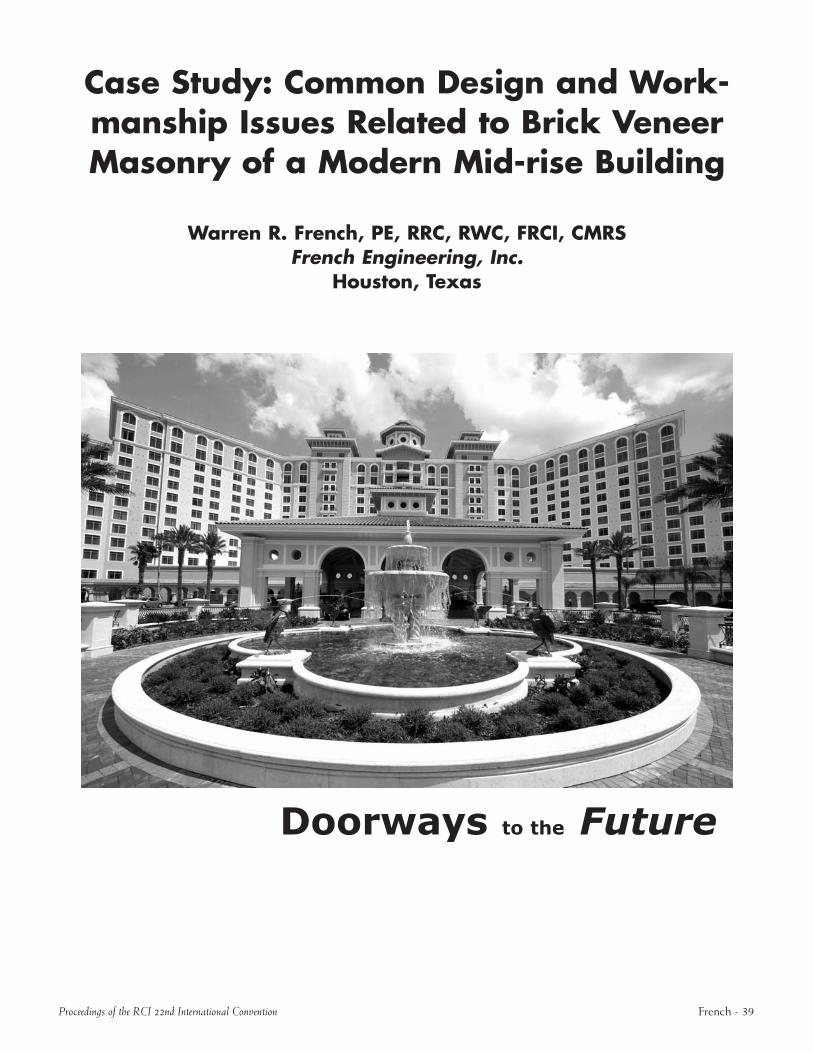
Case Study: Common Design and Workmanship Issues Related to Brick Veneer Masonry of a Modern Midrise Building
Warren R. French, PE, RRC, RWC, FRCI, CMRS French Engineering, Inc.
Houston, Texas
Doorways to the Future
Proceedings of the RCI 22nd International Convention French 39
ABSTRACT At the time of our investigation, the 100,000squarefoot, 12story, multifamily residential building had been constructed for only about four years. It consisted of a castinplace concrete structural frame and posttensioned floor slabs, with coldformed metal framing utilized as the wall infills. The metal studs had been covered with a gypsum sheathing and a #15 felt weather barrier, utilizing a 2inch air space or cavity and nominal 4inchthick brick veneer. The fenestration included a complex arrangement of four different colors of brick, as well as white cast stone elements at copings and periodic masonry string courses. In addition, the building included a threestory mansard composed of standing seam sheet metal roofing with a slight radiused configuration. Additional architectural elements included vertical notches and offsets, aluminumandglass curtain walls, and private balconies and terraces. Terraces and balconies were provided with a fluidapplied deck coating as a waterproofing application.
It is intended that this paper will present the results of observations made and testing conducted at the site over a period of months. This paper will derive specific conclusions related to the conditions encountered at this project and how these anomalies detrimentally affected the cladding system’s performance. Recommendations will be developed that could strengthen the original design and construction in order that these failures may be avoided in the future.
SPEAKER
WARREN R. FRENCH,PE, RRC, RWC, CCS is president of French Engineering, Inc. in Houston, Texas. Mr. French has over 30 years experience in design, engineering, and construction of commercial, industrial, and institutional buildings for both domestic and international projects. Special experience and abilities include analysis, design, testing, and inspection of all types of construction assemblies intended to resist moisture migration within buildings. Areas of expertise include all types of roofing systems, belowgrade and plazatype waterproofing, building sealants, wall cladding systems, plaster, EIFS, and all types of curtain walls.
Warren is a professional member of RCI, CSI, ASE, ASTM, the PostTensioning Institute, and the International Concrete Repair Institute. He has been a speaker at numerous conferences, symposiums, and national organization meetings, as well as presenting several inhouse seminars for major corporations and design firms, including Hilton Hotels Corporation, Marriott Corporation, Trammel Crow, and HKS Architects.
French 40 Proceedings of the RCI 22nd International Convention
Case Study: Common Design and Workmanship Issues Related to Brick Veneer Masonry of a Modern Midrise Building
INTRODUCTION AND BACK GROUND
This paper will present the findings of a forensic investigation conducted on a 12story, multifamily residential building recently constructed in New Orleans, Louisiana. We were retained by the owner’s representatives to assist in determining a cause for the interior water infiltration being experienced, as well as to develop a plan for cladding system remediation and renovation.
BUILDING DESCRIPTION
General Building
At the time of our investigation, the 100,000sqft, 12story, multifamily residential building that is the subject of this presentation had been constructed for only about four years. The building contains 118 one, two, and threebedroom apartments and 30,000 sq ft of common areas such as a library, craft room, multipurpose auditorium, an exercise center, dining room, private dining room, and business center.
It consists of a castinplace concrete structural frame and posttensioned floor slabs with coldformed metal framing utilized as the wall infills. The metal studs had been covered with gypsum sheathing and a #15 felt weather barrier, utilizing a 2inch air space or cavity and nominal 4inchthick brick veneer. The fenestration included a complex arrangement of four different colors of brick as well as white cast stone elements at copings and periodic masonry string courses.
Proceedings of the RCI 22nd International Convention
In addition, the building included a threestory mansard composed of standing seam sheet metal roofing with a slight radiused configuration. Additional architectural elements included vertical notches and offsets, a l um inum and glass curtain walls, and private balconies and terraces. Terraces and balconies were provided with a fluidapplied deck coating as a waterproofing application.
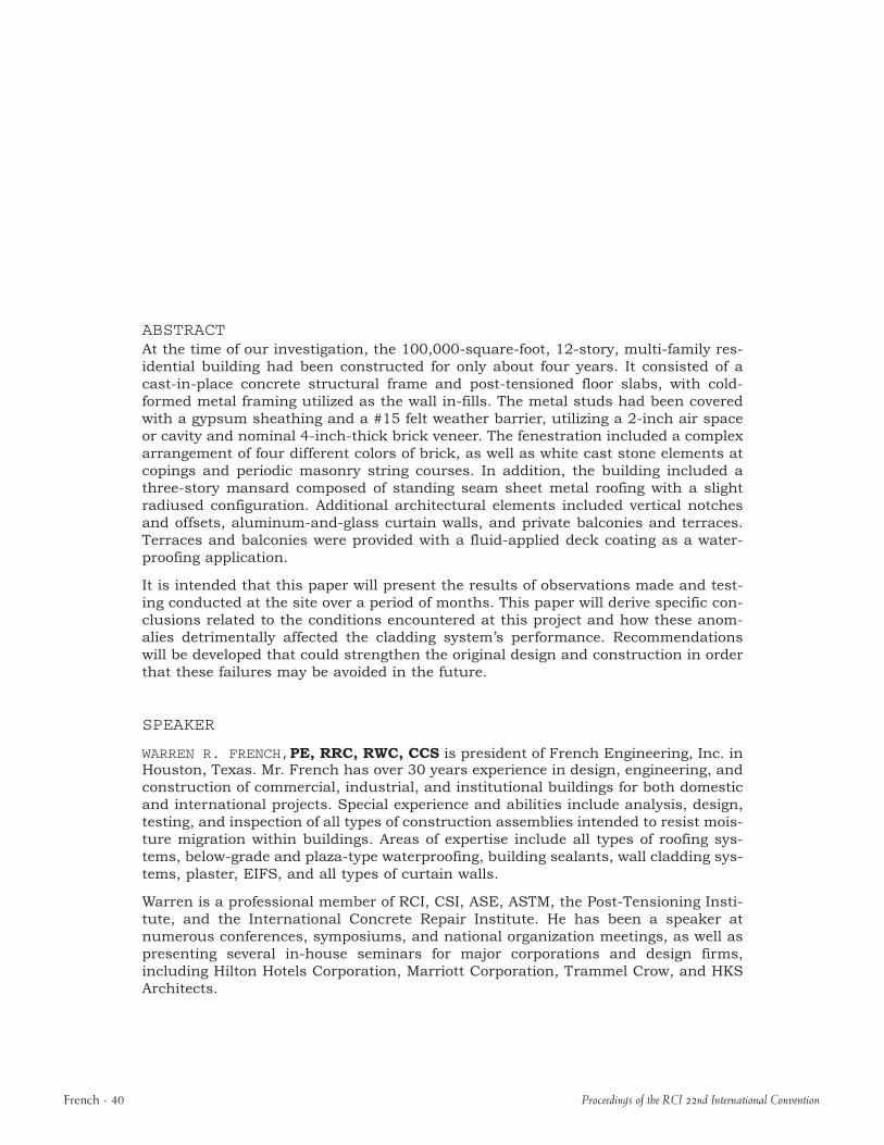
The east and west elevations are comprised primarily of brick veneer cladding up to the 11th floor level with one, two, and threepane punched windows installed approximately two feet below the top of slab at each floor level. The east and west elevations have recessed rectangular unit balconies and radiused unit balconies that protrude outward from the building between the fifth and twelfth floor levels. Storefront windows, arched storefront windows, and glass block windows are provided at the first floor. A prefinished metal mansard with one and twopane bay windows comprise the building perimeter at the 11th and 12th floor levels. A large open balcony
Figure 1 – Typical elevation showing intri-cate masonry.
deck exists along the west elevation at the second floor level.
A discontinuous building expansion joint traverses the building in the eastwest direction near the center of the building. The north and south elevations are clad with building finishes similar to those described at the east and west elevations. There is a gazebo structure adjacent to the northeast corner of the porte cochere and there is another gazebo struc
French 41
ture on the south elevation at the roof level. The north and south elevations also have a curtain wall that extends between the 5th and 12thfloor levels. Precast concrete copings accent the perimeter lower roof parapet walls, the balcony terrace handrail walls, and the handrail walls at the recessed unit balconies and the radiused unit balconies. Continuous painted steel handrails mounted on small masonry walls were provided at all balcony areas.
Precast concrete pavers were installed over rigid insulation and a concrete topping slab with a liquidapplied waterproofing deck coating at the unit balconies at the fifth floor level located on the north and south building elevations. Concrete pavers were also installed at the second floor balcony deck that extends along a portion of the west elevation. The remaining exterior balconies have a waterproofing deck coating applied to a concrete topping slab that slopes downward away from the building.
Exterior Wall Cladding Assemblies
Exterior wall cladding assemblies were comprised of brick masonry veneer installed on steel shelf angles that were attached to the underlying concrete slab at each floor. Brick ties were designed to be utilized at wall locations to provide additional lateral support. Elastomeric sealants have been installed at horizontal joints where shelf angles were occurring, at vertical construction joints of the brick veneer masonry cladding, and at window perimeters. Existing brick veneer masonry cladding is the original cladding system installed at this project.
The original brick masonry veneer was an elaborate mixture of four differently colored brick with different shapes installed in various bond patterns and brick
French 42
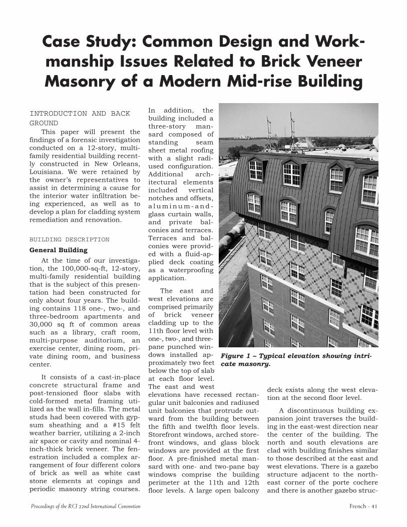
orientations, along with precast concrete copings to form corbels and accent bands along all building elevations. The brick masonry between the first and eighth floor levels was primarily red and installed in a running bond pattern. Wh i t e c o l o r e d brick and precast concrete copings were used to form a corbel accent band at the second floor level. Whitecolored brick was also used as an accent band at the ninth floor level. White, precast concrete was used to accent the edge of all balconies. Bricks of various colors were installed at the ninth and tenth floors Figure 2 – Cracks in brick veneer at corner. levels in a vertical stack bond pattern with colors aligned to form large running accent diamonds. The brick veneer masonry is typically supported by galvanized shelf angles at each floor level and galvanized steel lintels were provided at window and door heads.
Brief History
The property management for this facility indicated the building was completed and turned over to them for occupancy in 1998. The building envelope ostensibly remained relatively dry until Tropical Storm Bertha and Hurricane Isidore passed through the New Orleans, Louisiana, area in August and September 2002, respectively. The building owner furnished our firm with markedup floor plans that depict a total
of 22 locations between floor levels one and 11 where water intrusion problems were occurring and have resulted in considerable damage to the interior building finishes. Moisture damage at ten of these locations had required mold remediation.
Since these storms, the water intrusion had caused an ongoing operations problem and the building owner notified the architect and the general contractor to investigate and correct these problems. Initially, the general contractor responded in a timely manner and implemented certain limited repair attempts. However, the water intrusion continued throughout the project due to inadequate repairs, which as of our involvement had not corrected
Proceedings of the RCI 22nd International Convention
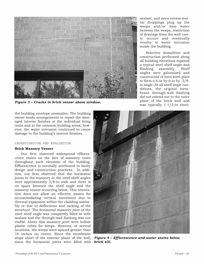
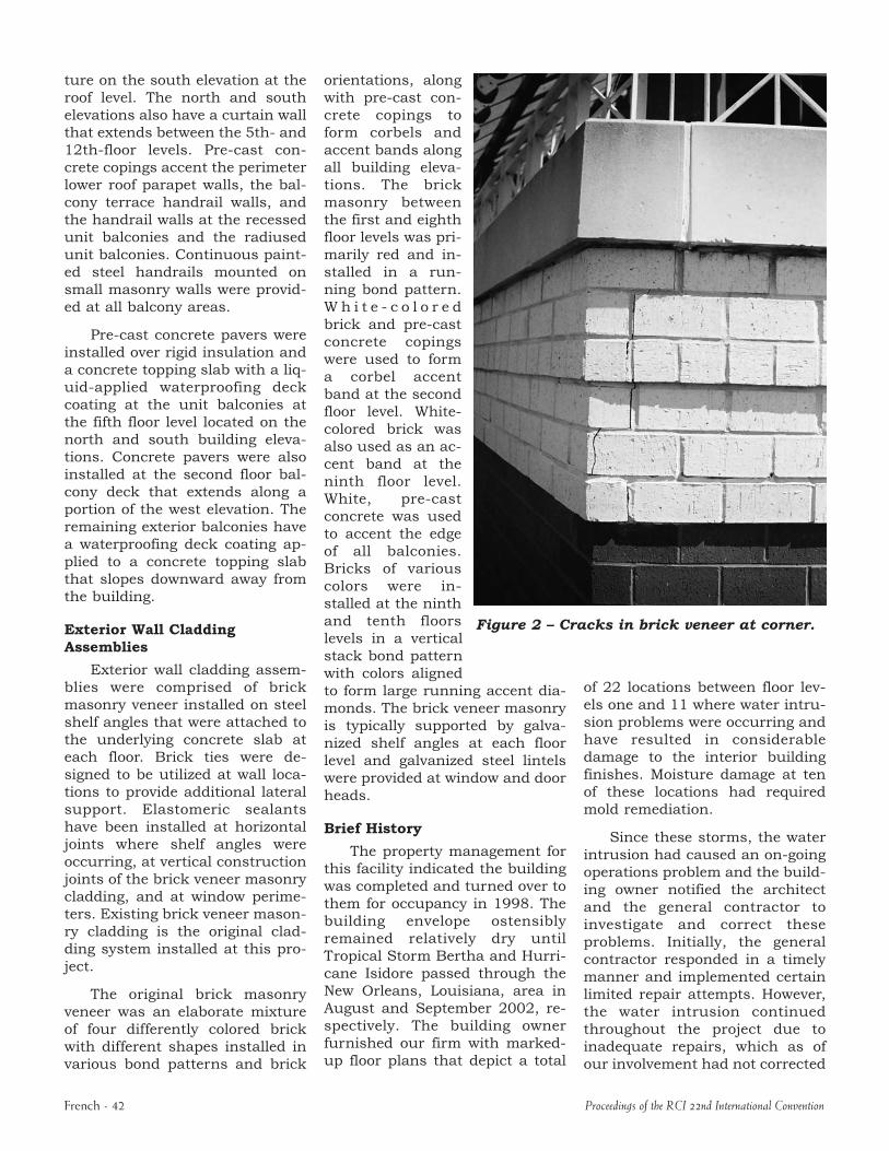
Figure 3 – Cracks in brick veneer above window.
the building envelope anomalies. The building owner made arrangements to repair the damaged interior finishes at the individual living units and at the common building areas; however, the water intrusion continued to cause damage to the building’s interior finishes.
INVESTIGATION AND EVALUATION
Brick Masonry Veneer
Our firm observed widespread efflorescence stains on the face of masonry units throughout each elevation of the building. Efflorescence is normally attributed to faulty design and construction practices. In addition, our firm observed that the horizontal joints in the masonry at the steel shelf angles were approximately 3/8in wide and there is no space between the shelf angle and the masonry veneer occurring below. This orientation does not allow an effective means for accommodating vertical movement due to thermal expansion within the cladding assembly or due to deflections and racking of the structure. The horizontal masonry joint at the steel shelf angle was completely filled in with sealant and the throughwall flashing was not visible. Above this masonry joint were hollow plastic tubes for weeps. However, at several locations, the weeps were spaced greater than 16 inches on center. Since the membrane stops short of the exterior plane of the wall, since the horizontal joints were filled with
sealant, and since excess mortar droppings plug up the weeps and/or dam water between the weeps, restriction of drainage from the wall cavity occurs and eventually results in water intrusion inside the building.
Selective demolition and construction performed along all building elevations exposed a typical steel shelf angle and flashing assembly. Shelf angles were galvanized and constructed of bent steel plate to form a 6in by 6in by 3/8in angle. At all shelf angle conditions, the original membrane throughwall flashing did not extend out to the outer plane of the brick wall and was typically 11/2in short.
Figure 4 – Efflorescence and water stains below brick sill.
Proceedings of the RCI 22nd International Convention French 43
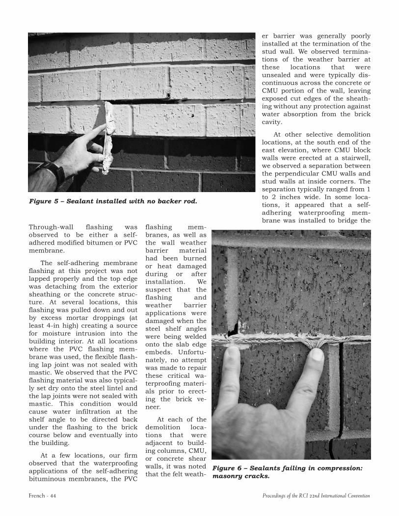
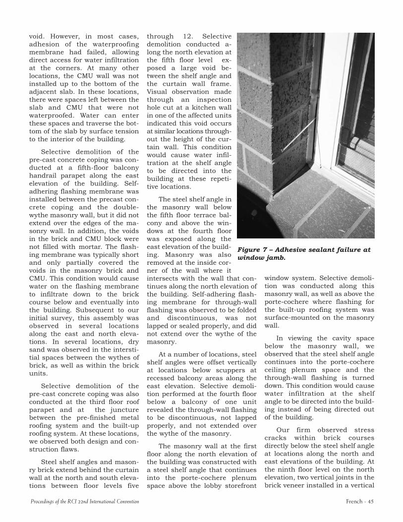
Figure 5 – Sealant installed with no backer rod.
Throughwall flashing was observed to be either a selfadhered modified bitumen or PVC membrane.
The selfadhering membrane flashing at this project was not lapped properly and the top edge was detaching from the exterior sheathing or the concrete structure. At several locations, this flashing was pulled down and out by excess mortar droppings (at least 4in high) creating a source for moisture intrusion into the building interior. At all locations where the PVC flashing membrane was used, the flexible flashing lap joint was not sealed with mastic. We observed that the PVC flashing material was also typically set dry onto the steel lintel and the lap joints were not sealed with mastic. This condition would cause water infiltration at the shelf angle to be directed back under the flashing to the brick course below and eventually into the building.
At a few locations, our firm observed that the waterproofing applications of the selfadhering bituminous membranes, the PVC
flashing membranes, as well as the wall weather barrier material had been burned or heat damaged during or after installation. We suspect that the flashing and weather barrier applications were damaged when the steel shelf angles were being welded onto the slab edge embeds. Unfortunately, no attempt was made to repair these critical waterproofing materials prior to erecting the brick veneer.
At each of the demolition locations that were adjacent to building columns, CMU, or concrete shear walls, it was noted that the felt weath
er barrier was generally poorly installed at the termination of the stud wall. We observed terminations of the weather barrier at these locations that were unsealed and were typically discontinuous across the concrete or CMU portion of the wall, leaving exposed cut edges of the sheathing without any protection against water absorption from the brick cavity.
At other selective demolition locations, at the south end of the east elevation, where CMU block walls were erected at a stairwell, we observed a separation between the perpendicular CMU walls and stud walls at inside corners. The separation typically ranged from 1 to 2 inches wide. In some locations, it appeared that a selfadhering waterproofing membrane was installed to bridge the
Figure 6 – Sealants failing in compression: masonry cracks.
French 44 Proceedings of the RCI 22nd International Convention
void. However, in most cases, adhesion of the waterproofing membrane had failed, allowing direct access for water infiltration at the corners. At many other locations, the CMU wall was not installed up to the bottom of the adjacent slab. In these locations, there were spaces left between the slab and CMU that were not waterproofed. Water can enter these spaces and traverse the bottom of the slab by surface tension to the interior of the building.
Selective demolition of the precast concrete coping was conducted at a fifthfloor balcony handrail parapet along the east elevation of the building. Selfadhering flashing membrane was installed between the precast concrete coping and the doublewythe masonry wall, but it did not extend over the edges of the masonry wall. In addition, the voids in the brick and CMU block were not filled with mortar. The flashing membrane was typically short and only partially covered the voids in the masonry brick and CMU. This condition would cause water on the flashing membrane to infiltrate down to the brick course below and eventually into the building. Subsequent to our initial survey, this assembly was observed in several locations along the east and north elevations. In several locations, dry sand was observed in the interstitial spaces between the wythes of brick, as well as within the brick units.
Selective demolition of the precast concrete coping was also conducted at the third floor roof parapet and at the juncture between the prefinished metal roofing system and the builtup roofing system. At these locations, we observed both design and construction flaws.
Steel shelf angles and masonry brick extend behind the curtain wall at the north and south elevations between floor levels five
Proceedings of the RCI 22nd International Convention
through 12. Selective demolition conducted along the north elevation at the fifth floor level exposed a large void between the shelf angle and the curtain wall frame. Visual observation made through an inspection hole cut at a kitchen wall in one of the affected units indicated this void occurs at similar locations throughout the height of the curtain wall. This condition would cause water infiltration at the shelf angle to be directed into the building at these repetitive locations.
The steel shelf angle in the masonry wall below the fifth floor terrace balcony and above the windows at the fourth floor was exposed along the east elevation of the building. Masonry was also
Figure 7 – Adhesive sealant failure at window jamb.
removed at the inside corner of the wall where it intersects with the wall that continues along the north elevation of the building. Selfadhering flashing membrane for throughwall flashing was observed to be folded and discontinuous, was not lapped or sealed properly, and did not extend over the wythe of the masonry.
At a number of locations, steel shelf angles were offset vertically at locations below scuppers at recessed balcony areas along the east elevation. Selective demolition performed at the fourth floor below a balcony of one unit revealed the throughwall flashing to be discontinuous, not lapped properly, and not extended over the wythe of the masonry.
The masonry wall at the first floor along the north elevation of the building was constructed with a steel shelf angle that continues into the portecochere plenum space above the lobby storefront
window system. Selective demolition was conducted along this masonry wall, as well as above the portecochere where flashing for the builtup roofing system was surfacemounted on the masonry wall.
In viewing the cavity space below the masonry wall, we observed that the steel shelf angle continues into the portecochere ceiling plenum space and the throughwall flashing is turned down. This condition would cause water infiltration at the shelf angle to be directed into the building instead of being directed out of the building.
Our firm observed stress cracks within brick courses directly below the steel shelf angle at locations along the north and east elevations of the building. At the ninth floor level on the north elevation, two vertical joints in the brick veneer installed in a vertical
French 45
stack bond were repaired with sealants due to an opening in the mortar joint. Additional stress cracks, similarly repaired with sealant, were also observed at the south end of the east elevation, on lower floors where the brick is in a running bond. This cracking and displacement is normally caused by excessive compressive loads being imposed on individual brick masonry units without adequate joint relief below the shelf angle or due to the lack of a shelf angle.
Brick Veneer Wall Ties
During the investigation and renovation at this project, we observed and documented numerous anomalies associated with the brick veneer wall tie selection and installation. Brick ties are intended to provide lateral support for masonry veneer assemblies. Omitting or improperly installing brick ties on highrise buildings can be detrimental to the structural integrity of the cladding system, especially in areas affected by hurricane force winds.
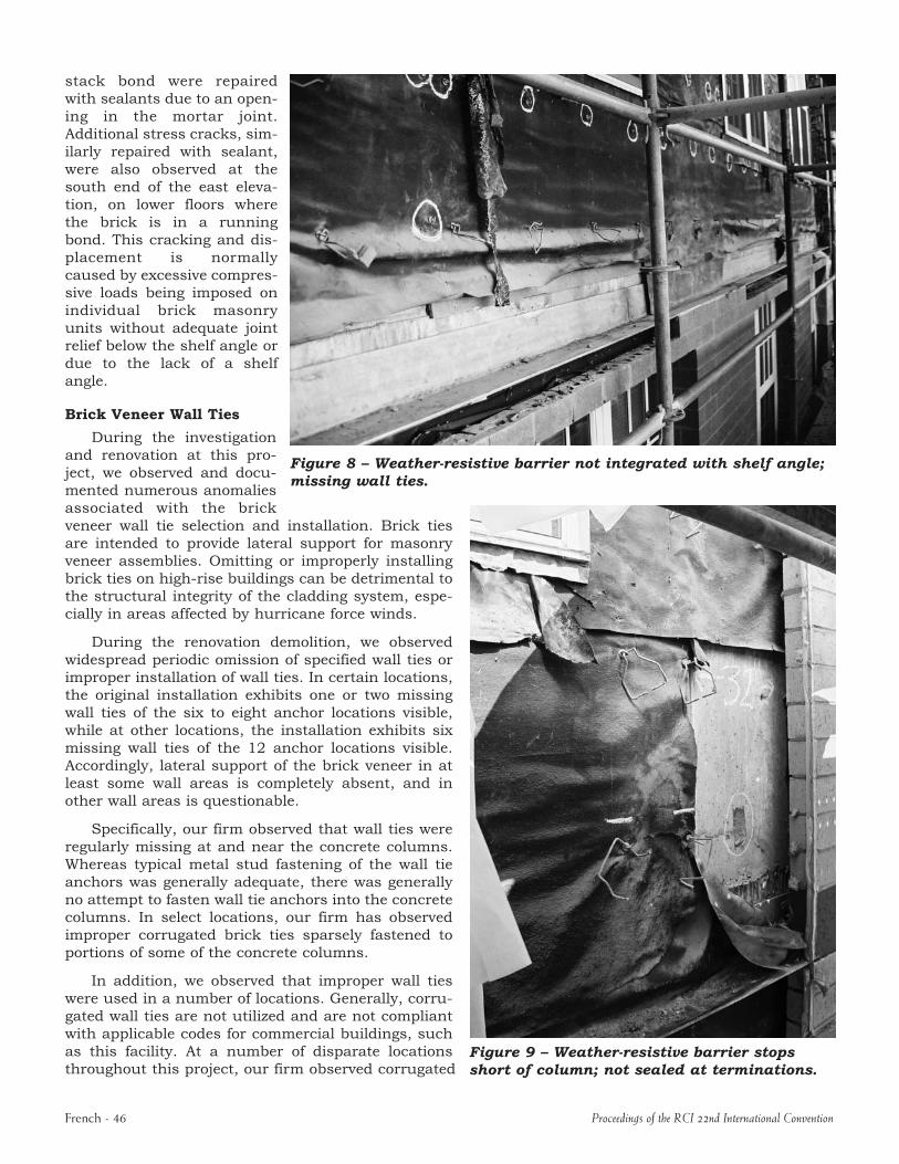
During the renovation demolition, we observed widespread periodic omission of specified wall ties or improper installation of wall ties. In certain locations, the original installation exhibits one or two missing wall ties of the six to eight anchor locations visible, while at other locations, the installation exhibits six missing wall ties of the 12 anchor locations visible. Accordingly, lateral support of the brick veneer in at least some wall areas is completely absent, and in other wall areas is questionable.
Specifically, our firm observed that wall ties were regularly missing at and near the concrete columns. Whereas typical metal stud fastening of the wall tie anchors was generally adequate, there was generally no attempt to fasten wall tie anchors into the concrete columns. In select locations, our firm has observed improper corrugated brick ties sparsely fastened to portions of some of the concrete columns.
In addition, we observed that improper wall ties were used in a number of locations. Generally, corrugated wall ties are not utilized and are not compliant with applicable codes for commercial buildings, such as this facility. At a number of disparate locations throughout this project, our firm observed corrugated
Figure 8 – Weather-resistive barrier not integrated with shelf angle; missing wall ties.
Figure 9 – Weather-resistive barrier stops short of column; not sealed at terminations.
French 46 Proceedings of the RCI 22nd International Convention
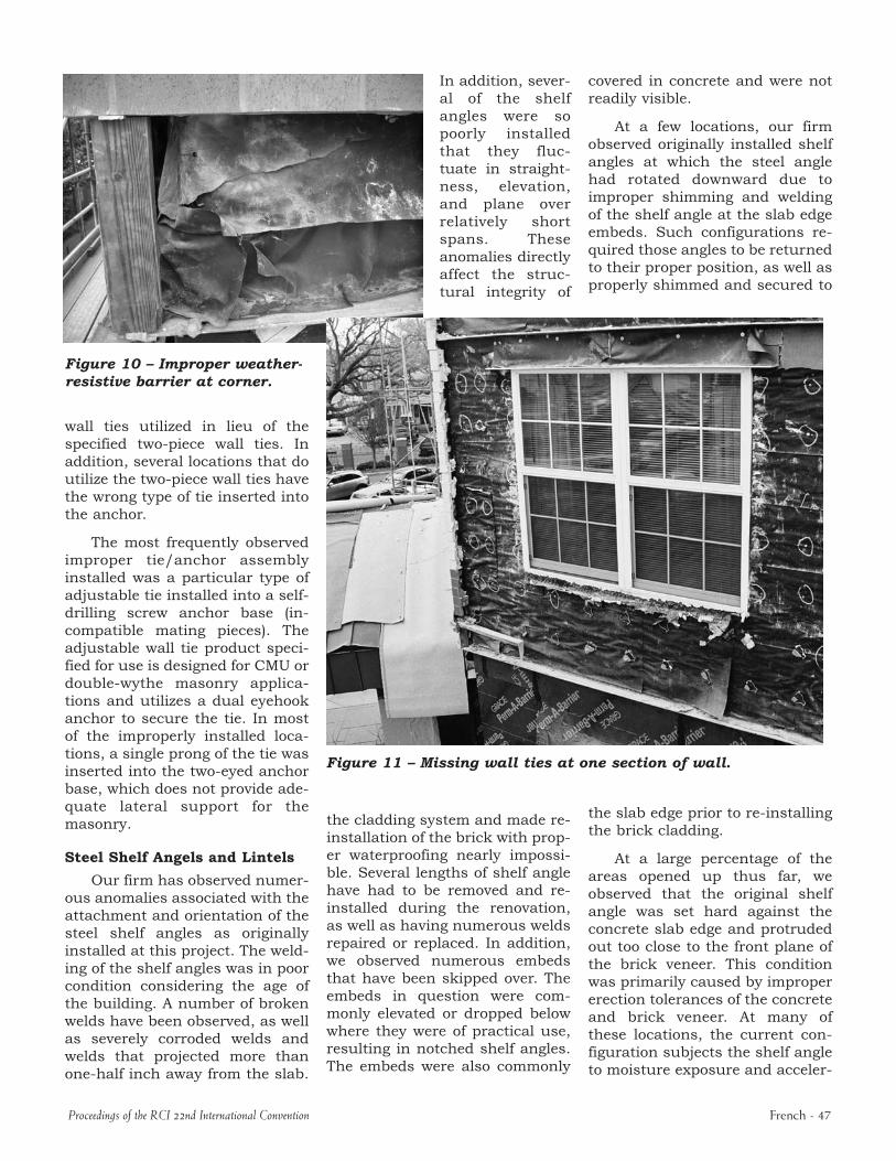
Figure 10 – Improper weather-resistive barrier at corner.
In addition, several of the shelf angles were so poorly installed that they fluctuate in straightness, elevation, and plane over relatively short spans. These anomalies directly affect the structural integrity of
wall ties utilized in lieu of the specified twopiece wall ties. In addition, several locations that do utilize the twopiece wall ties have the wrong type of tie inserted into the anchor.
The most frequently observed improper tie/anchor assembly installed was a particular type of adjustable tie installed into a selfdrilling screw anchor base (incompatible mating pieces). The adjustable wall tie product specified for use is designed for CMU or doublewythe masonry applications and utilizes a dual eyehook anchor to secure the tie. In most of the improperly installed locations, a single prong of the tie was inserted into the twoeyed anchor base, which does not provide adequate lateral support for the masonry.
Steel Shelf Angels and Lintels
Our firm has observed numerous anomalies associated with the attachment and orientation of the steel shelf angles as originally installed at this project. The welding of the shelf angles was in poor condition considering the age of the building. A number of broken welds have been observed, as well as severely corroded welds and welds that projected more than onehalf inch away from the slab.
Proceedings of the RCI 22nd International Convention
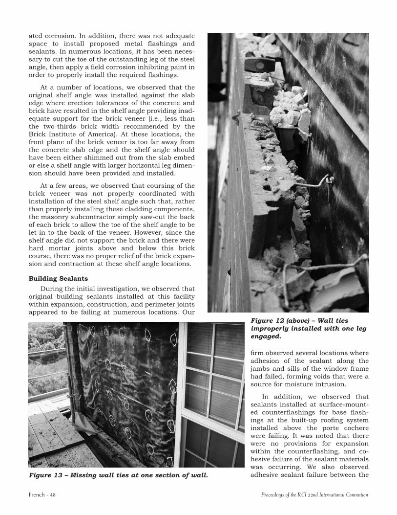
Figure 11 – Missing wall ties at one section of wall.
the cladding system and made reinstallation of the brick with proper waterproofing nearly impossible. Several lengths of shelf angle have had to be removed and reinstalled during the renovation, as well as having numerous welds repaired or replaced. In addition, we observed numerous embeds that have been skipped over. The embeds in question were commonly elevated or dropped below where they were of practical use, resulting in notched shelf angles. The embeds were also commonly
covered in concrete and were not readily visible.
At a few locations, our firm observed originally installed shelf angles at which the steel angle had rotated downward due to improper shimming and welding of the shelf angle at the slab edge embeds. Such configurations required those angles to be returned to their proper position, as well as properly shimmed and secured to
the slab edge prior to reinstalling the brick cladding.
At a large percentage of the areas opened up thus far, we observed that the original shelf angle was set hard against the concrete slab edge and protruded out too close to the front plane of the brick veneer. This condition was primarily caused by improper erection tolerances of the concrete and brick veneer. At many of these locations, the current configuration subjects the shelf angle to moisture exposure and acceler
French 47
ated corrosion. In addition, there was not adequate space to install proposed metal flashings and sealants. In numerous locations, it has been necessary to cut the toe of the outstanding leg of the steel angle, then apply a field corrosion inhibiting paint in order to properly install the required flashings.
At a number of locations, we observed that the original shelf angle was installed against the slab edge where erection tolerances of the concrete and brick have resulted in the shelf angle providing inadequate support for the brick veneer (i.e., less than the twothirds brick width recommended by the Brick Institute of America). At these locations, the front plane of the brick veneer is too far away from the concrete slab edge and the shelf angle should have been either shimmed out from the slab embed or else a shelf angle with larger horizontal leg dimension should have been provided and installed.
At a few areas, we observed that coursing of the brick veneer was not properly coordinated with installation of the steel shelf angle such that, rather than properly installing these cladding components, the masonry subcontractor simply sawcut the back of each brick to allow the toe of the shelf angle to be letin to the back of the veneer. However, since the shelf angle did not support the brick and there were hard mortar joints above and below this brick course, there was no proper relief of the brick expansion and contraction at these shelf angle locations.
Building Sealants
During the initial investigation, we observed that original building sealants installed at this facility within expansion, construction, and perimeter joints appeared to be failing at numerous locations. Our
Figure 13 – Missing wall ties at one section of wall.
Figure 12 (above) – Wall ties improperly installed with one leg engaged.
firm observed several locations where adhesion of the sealant along the jambs and sills of the window frame had failed, forming voids that were a source for moisture intrusion.
In addition, we observed that sealants installed at surfacemounted counterflashings for base flashings at the builtup roofing system installed above the porte cochere were failing. It was noted that there were no provisions for expansion within the counterflashing, and cohesive failure of the sealant materials was occurring. We also observed adhesive sealant failure between the
French 48 Proceedings of the RCI 22nd International Convention
metal scupper and masonry at several unit balcony locations.
Windows, Storefronts, and End Wall Curtain Walls
Field leak testing performed on punched windows along the east and north elevation proved inconclusive due to the fact that no visual indication of water intrusion through the window assembly was observed on the interior of the building. Prior to leak testing, the juncture between the window frame and the masonry was tapedoff to isolate the window assembly. In our opinion, the field leak testing results give evidence to the fact that previous leaks were more than likely associated with sealant failures and brick cladding deficiencies, such as throughwall flashing, improper steel shelf angles, and the lack of end dam flashing at steel shelf angles and lintels.
Our firm observed numerous windows at all building elevations where the sealant was failing and a source for moisture intrusion. AAMA 501.2 field leak testing performed on a punched window at the north elevation (where sealant adhesive failure exists along the window jambs and sill) resulted in immediate water intrusion to the interior. Selective demolition was performed and revealed that the flanged edge of the typical window frame had not been provided with sufficient thickness to leave an adequate bonding surface for sealants. We also observed that the selfadhering window head flashing was pulled down by mortar droppings and there were no end dams within that flashing as recommended by BIA. The selfadhering windowsill flashing was folded up to form end dams, but the length of flashing was not turned up along the inside face of the window frame to complete the end dam. Also, the windowsill flashing did not extend to the outer plane of the brick veneer and could divert water to the brick
Proceedings of the RCI 22nd International Convention
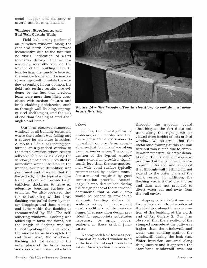
Figure 14 – Shelf angle offset in elevation; no end dam at mem-brane flashing.
below.
During the investigation of problems, our firm observed that the window frame extrusions do not exhibit or provide an acceptable sealant bond surface along their perimeter edges. The configuration of the typical window frame extrusion provided significantly less than the onequarterinchwide bond surface typically recommended by sealant manufacturers and required by good construction practice. Accordingly, it was determined during the design phase of the renovation documents that a caulk stop would be needed to provide an adequate bonding surface for sealants along the jambs and head conditions of the window frame. The renovation design provided for appropriate substrates necessary to apply proper sealants at these critical junctures.
A spray rack leak test was performed at an arched window head at the first floor along the east elevation. An inspection hole was cut
through the gypsum board sheathing at the furredout column along the right jamb (as viewed from inside) of this arched window. We observed that the metal stud framing at this column furrout was rusted due to chronic water exposure. Selective demolition of the brick veneer was also performed at the window headtocolumn interface and revealed that throughwall flashing did not extend to the outer plane of the brick veneer. In addition, the flashing was installed dry and an end dam was not provided to divert water out and away from the wall cavity.
A spray rack leak test was performed on a storefront window at the first floor along the west elevation of the building at the north end of Art Gallery 2. Our firm observed that the elevation of the stamped concrete at the patio was higher than the windowsill and water was ponding against the windowsill during the leak test. Water intrusion occurred along this juncture and it appeared the storefront windowsill was not
French 49
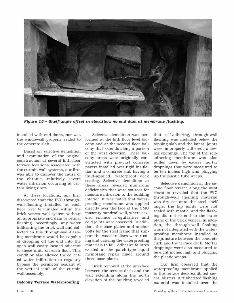
Figure 15 – Shelf angle offset in elevation; no end dam at membrane flashing.
installed with end dams, nor was the windowsill properly sealed to the concrete slab.
Based on selective demolition and examination of the original construction at several fifth floor terrace locations associated with the curtain wall systems, our firm was able to discover the cause of the chronic, relatively severe water intrusion occurring at certain living units.
At these locations, our firm discovered that the PVC throughwallflashing installed at each floor level terminated within the brick veneer wall system without an appropriate end dam or return flashing. Accordingly, any water infiltrating the brick wall and collected on this throughwallflashing membrane would be capable of dropping off the end into the open wall cavity located adjacent to these units on each floor. This condition also allowed the collected water infiltration to regularly bypass the perimeter sealant at the vertical jamb of the curtain wall assembly.
Balcony Terrace Waterproofing
French 50
Selective demolition was performed at the fifth floor level balcony and at the second floor balcony that extends along a portion of the west elevation. These balcony areas were originally constructed with precast concrete pavers installed over rigid insulation and a concrete slab having a fluidapplied, waterproof deck coating. Selective demolition at these areas revealed numerous deficiencies that were sources for moisture intrusion to the building interior. It was noted that waterproofing membrane was applied directly over the face of the CMU masonry handrail wall, where several surface irregularities and cold joints were observed. In addition, the base plates and anchor bolts for the steel frame that support the wood trellises were rusting and causing the waterproofing materials to fail. Adhesive failures existed at the patchtype liquid membrane repair made around these base plates.
Brick removed at the interface between the terrace deck and the wall extending along the north elevation of the building revealed
that selfadhering, throughwall flashing was installed below the topping slab and the lateral joints were improperly adhered, allowing openings. The top of the selfadhering membrane was also pulled down by excess mortar droppings that were measured to be ten inches high and plugging up the plastic tube weeps.
Selective demolition at the second floor terrace along the west elevation revealed that the PVC throughwall flashing material was dry set onto the steel shelf angle, the lap joints were not sealed with mastic, and the flashing did not extend to the outer plane of the brick veneer. In addition, the throughwall flashing was not integrated with the waterproofing membrane installed at the juncture between the concrete curb and the terrace deck. Mortar droppings were also measured to be eight inches high and plugging the plastic weeps.
Our firm observed that the waterproofing membrane applied to the terrace deck exhibited several blisters. A rubberized flashing material was installed over the
Proceedings of the RCI 22nd International Convention
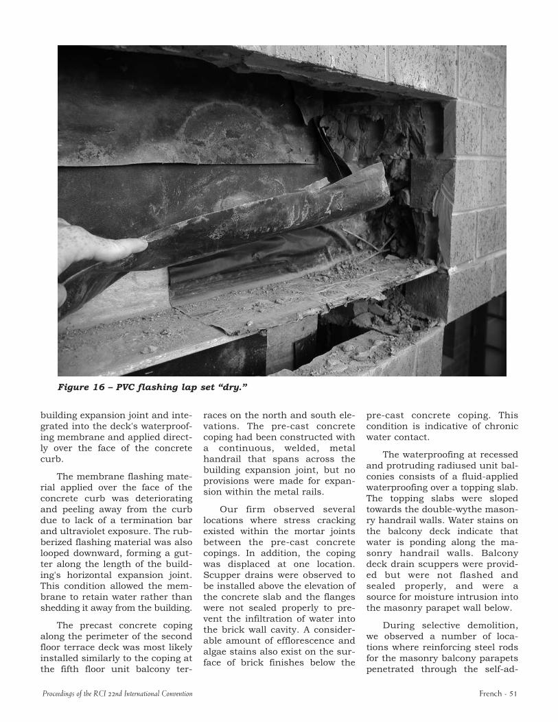
Figure 16 – PVC flashing lap set “dry.”
building expansion joint and integrated into the deck's waterproofing membrane and applied directly over the face of the concrete curb.
The membrane flashing material applied over the face of the concrete curb was deteriorating and peeling away from the curb due to lack of a termination bar and ultraviolet exposure. The rubberized flashing material was also looped downward, forming a gutter along the length of the building's horizontal expansion joint. This condition allowed the membrane to retain water rather than shedding it away from the building.
The precast concrete coping along the perimeter of the second floor terrace deck was most likely installed similarly to the coping at the fifth floor unit balcony ter
Proceedings of the RCI 22nd International Convention
races on the north and south elevations. The precast concrete coping had been constructed with a continuous, welded, metal handrail that spans across the building expansion joint, but no provisions were made for expansion within the metal rails.
Our firm observed several locations where stress cracking existed within the mortar joints between the precast concrete copings. In addition, the coping was displaced at one location. Scupper drains were observed to be installed above the elevation of the concrete slab and the flanges were not sealed properly to prevent the infiltration of water into the brick wall cavity. A considerable amount of efflorescence and algae stains also exist on the surface of brick finishes below the
precast concrete coping. This condition is indicative of chronic water contact.
The waterproofing at recessed and protruding radiused unit balconies consists of a fluidapplied waterproofing over a topping slab. The topping slabs were sloped towards the doublewythe masonry handrail walls. Water stains on the balcony deck indicate that water is ponding along the masonry handrail walls. Balcony deck drain scuppers were provided but were not flashed and sealed properly, and were a source for moisture intrusion into the masonry parapet wall below.
During selective demolition, we observed a number of locations where reinforcing steel rods for the masonry balcony parapets penetrated through the selfad
French 51
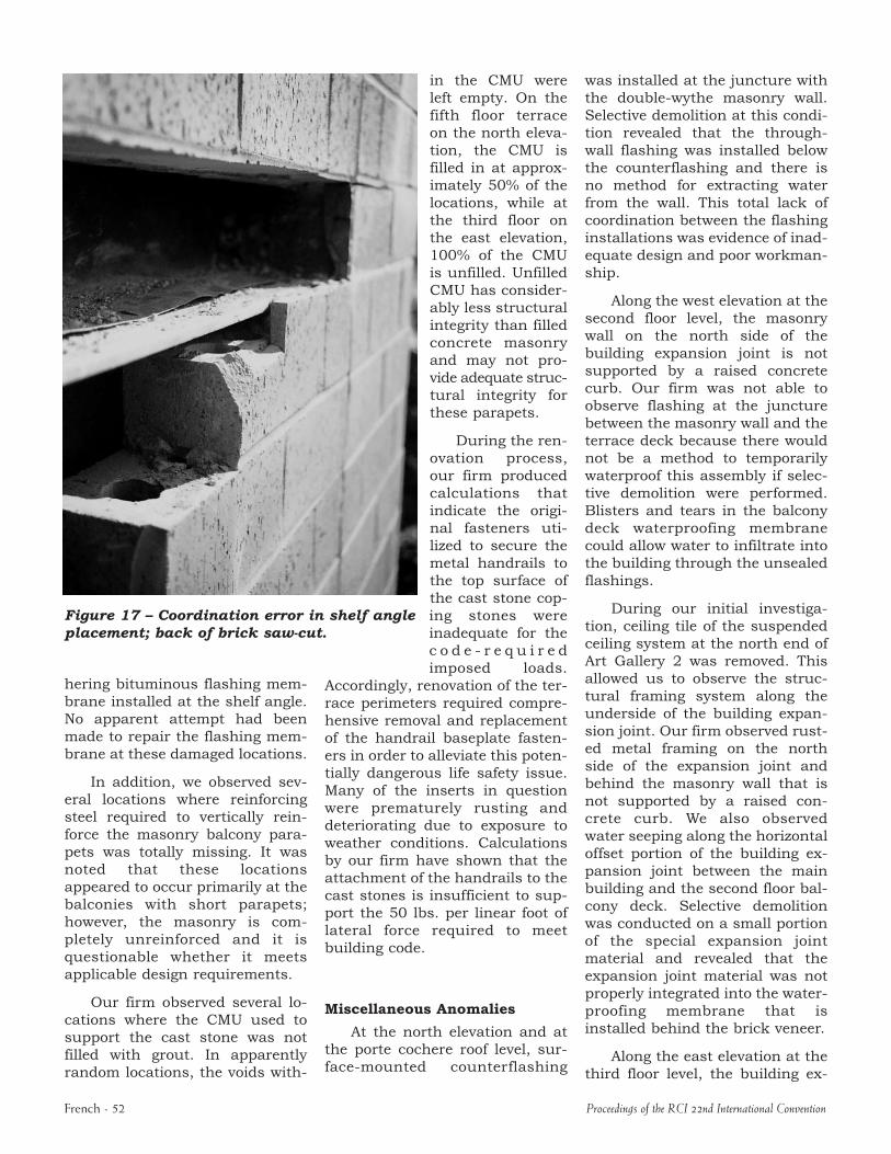
Figure 17 – Coordination error in shelf angle placement; back of brick saw-cut.
in the CMU were left empty. On the fifth floor terrace on the north elevation, the CMU is filled in at approximately 50% of the locations, while at the third floor on the east elevation, 100% of the CMU is unfilled. Unfilled CMU has considerably less structural integrity than filled concrete masonry and may not provide adequate structural integrity for these parapets.
During the renovation process, our firm produced calculations that indicate the original fasteners utilized to secure the metal handrails to the top surface of the cast stone coping stones were inadequate for the c o d e r e q u i r e d imposed loads.
Accordingly, renovation of the terrace perimeters required comprehensive removal and replacement of the handrail baseplate fasteners in order to alleviate this potentially dangerous life safety issue. Many of the inserts in question were prematurely rusting and deteriorating due to exposure to weather conditions. Calculations by our firm have shown that the attachment of the handrails to the cast stones is insufficient to support the 50 lbs. per linear foot of lateral force required to meet building code.
Miscellaneous Anomalies
At the north elevation and at the porte cochere roof level, surfacemounted counterflashing
hering bituminous flashing membrane installed at the shelf angle. No apparent attempt had been made to repair the flashing membrane at these damaged locations.
In addition, we observed several locations where reinforcing steel required to vertically reinforce the masonry balcony parapets was totally missing. It was noted that these locations appeared to occur primarily at the balconies with short parapets; however, the masonry is completely unreinforced and it is questionable whether it meets applicable design requirements.
Our firm observed several locations where the CMU used to support the cast stone was not filled with grout. In apparently random locations, the voids with
French 52
was installed at the juncture with the doublewythe masonry wall. Selective demolition at this condition revealed that the throughwall flashing was installed below the counterflashing and there is no method for extracting water from the wall. This total lack of coordination between the flashing installations was evidence of inadequate design and poor workmanship.
Along the west elevation at the second floor level, the masonry wall on the north side of the building expansion joint is not supported by a raised concrete curb. Our firm was not able to observe flashing at the juncture between the masonry wall and the terrace deck because there would not be a method to temporarily waterproof this assembly if selective demolition were performed. Blisters and tears in the balcony deck waterproofing membrane could allow water to infiltrate into the building through the unsealed flashings.
During our initial investigation, ceiling tile of the suspended ceiling system at the north end of Art Gallery 2 was removed. This allowed us to observe the structural framing system along the underside of the building expansion joint. Our firm observed rusted metal framing on the north side of the expansion joint and behind the masonry wall that is not supported by a raised concrete curb. We also observed water seeping along the horizontal offset portion of the building expansion joint between the main building and the second floor balcony deck. Selective demolition was conducted on a small portion of the special expansion joint material and revealed that the expansion joint material was not properly integrated into the waterproofing membrane that is installed behind the brick veneer.
Along the east elevation at the third floor level, the building ex
Proceedings of the RCI 22nd International Convention
pansion joint is horizontally offset in the northsouth direction between the masonry wall and the metal roofing system. Our firm observed that no provisions for expansion in either the longitudinal or traverse directions were designed or constructed for the prefinished metal roof system that traverses the building expansion joint along the east elevation at the third floor level. The prefinished metal roofing system was observed to be oil canning and was installed directly under the precast concrete coping. Our firm observed water ponding on the metal roof and along the inside face of the precast concrete coping due to the lack of adequate slope for positive drainage towards scuppers. Also, thermal expansion in the prefinished metal roofing system is causing the seams to separate and buckle at various locations.
Our firm observed several scuppers at unit balconies that were not installed and flashed properly. Voids exist between the flanges of the metal scupper and masonry and were a point source for moisture intrusion. A recessed balcony condition that we viewed at one of the units also exhibited water ponding stains along the length of the handrail parapet wall due to the lack of adequate slope towards the scupper.
We observed that the elevation of stamped concrete at the patio on the west side of the building was higher than the building slab at the storefront window system. Water was ponding against the storefront windowsill and infiltrating the building.
There were numerous locations where trash of various kinds was found within the wall cavity, including empty masonry cement paper bags, Visqueen, and miscellaneous construction debris. Although not detrimental to the wall cladding itself, these cellulose materials will absorb and retain
Proceedings of the RCI 22nd International Convention
water within the wall, provide a food source for termites, and should not have been stashed behind the veneer during the original construction.
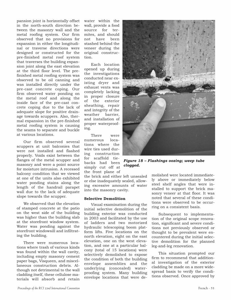
Each location opened up during the investigations conducted near existing dryer and exhaust vents was completely lacking in proper closure of the exterior sheathing, repair and integrity of the weather barrier, and installation of proper waterproofing.
There were numerous locations where the wire ties used during construction for scaffold tiebacks had been simply cut off at the front plane of the brick and either left unsealed or else inadequately sealed, allowing excessive amounts of water into the masonry cavity.
Selective Demolition
Visual examination during the initial selective demolition of the building exterior was conducted in 2003 and facilitated by the use of ladders and two motorized hydraulic telescoping boom platform lifts. Five locations on the north elevation, eight on the east elevation, one on the west elevation, and one at a particular balcony (total of 15 locations) were selectively demolished to expose the condition of both the building envelope assemblies and the underlying (concealed) waterproofing system. Many building envelope locations that were de
Figure 18 – Flashings oozing; weep tube clogged.
molished were located immediately above or immediately below steel shelf angles that were installed to support the brick masonry veneer at that floor. It was noted that several of these conditions were observed to be occurring on a consistent basis.
Subsequent to implementation of the original scope renovation, significant and severe conditions not previously observed or thought to be prevalent were encountered during the initial selective demolition for the planned legandleg renovation.
This situation prompted our firm to recommend that additional investigation of the exterior cladding be made on a more widespread basis to verify the conditions observed. Once approved by
French 53
the building owner, we performed limited selective demolition openings at all elevations of the building on an additional 49 locations occurring at various floor levels. These additional investigations were facilitated by the use of frame scaffolding and motorized hydraulic telescoping boom platform lifts. Documentation of the conditions observed at those locations was made by field notes, sketches, and photographs.
In general, the conditions revealed at these additional study locations were repetitive and consistent with the observations made at the initial legandleg selective demolition areas that prompted the study. Specifically, our firm observed: 1) significant and widespread wall areas where appropriate brick veneer ties had been omitted or improperly installed, 2) unsealed penetrations through the exterior sheathing at the drainage cavity, 3) improper installation of shelf angle flashing membranes, 4) inconsistent and discontinuous shelfangle flashing, 5) flexible electrical conduit located within the brick veneer drainage cavity, and 6) unsupported or improperly supported steel shelf angles.
An analysis of the results from the initial selective demolition related to the legandleg renovation, as well as the additional investigation of these 49 locations, ultimately led to a recommendation by our firm that the entire exterior brick cladding be completely removed and replaced.
This recommendation was approved by the building owner and a change order was written to increase the scope of work to a
French 54
c om p r e h e n s i v e cladding renovation. Additional materials were ordered and the comprehensive cladding renovation was begun in earnest during December of 2004.
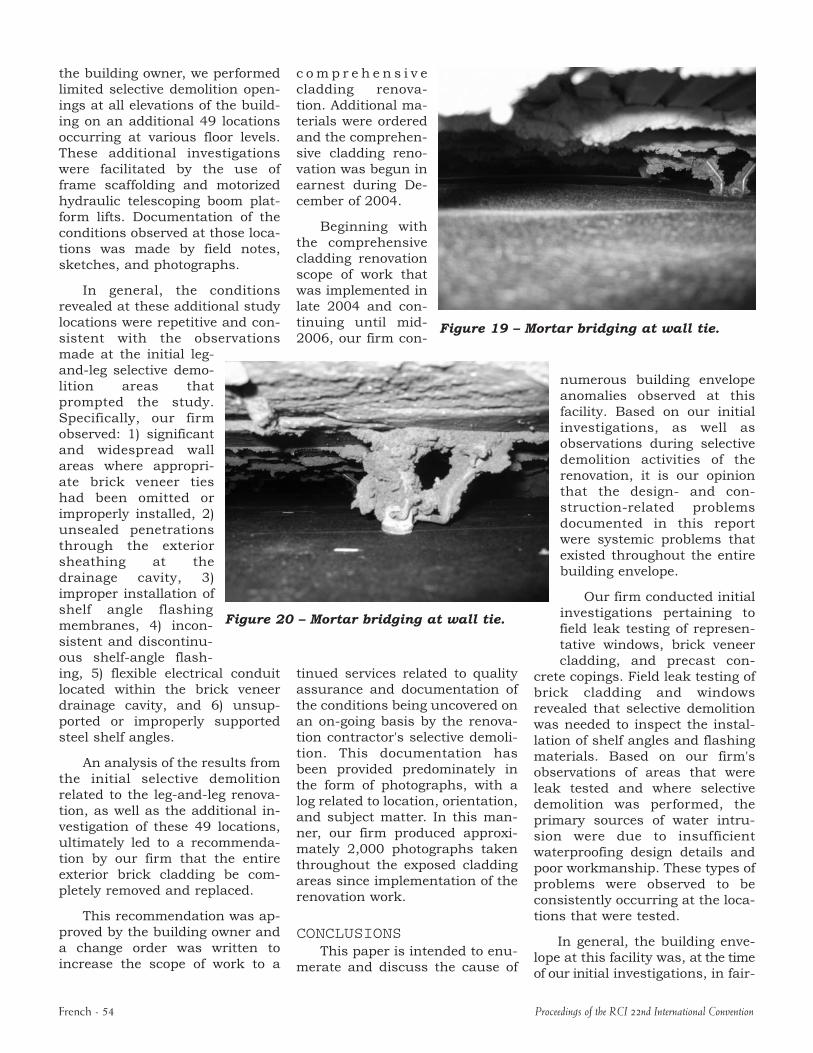
Beginning with the comprehensive cladding renovation scope of work that was implemented in late 2004 and continuing until mid Figure 19 – Mortar bridging at wall tie. 2006, our firm con
Figure 20 – Mortar bridging at wall tie.
tinued services related to quality assurance and documentation of the conditions being uncovered on an ongoing basis by the renovation contractor's selective demolition. This documentation has been provided predominately in the form of photographs, with a log related to location, orientation, and subject matter. In this manner, our firm produced approximately 2,000 photographs taken throughout the exposed cladding areas since implementation of the renovation work.
CONCLUSIONS This paper is intended to enu
merate and discuss the cause of
numerous building envelope anomalies observed at this facility. Based on our initial investigations, as well as observations during selective demolition activities of the renovation, it is our opinion that the design and constructionrelated problems documented in this report were systemic problems that existed throughout the entire building envelope.
Our firm conducted initial investigations pertaining to field leak testing of representative windows, brick veneer cladding, and precast con
crete copings. Field leak testing of brick cladding and windows revealed that selective demolition was needed to inspect the installation of shelf angles and flashing materials. Based on our firm's observations of areas that were leak tested and where selective demolition was performed, the primary sources of water intrusion were due to insufficient waterproofing design details and poor workmanship. These types of problems were observed to be consistently occurring at the locations that were tested.
In general, the building envelope at this facility was, at the time of our initial investigations, in fair
Proceedings of the RCI 22nd International Convention
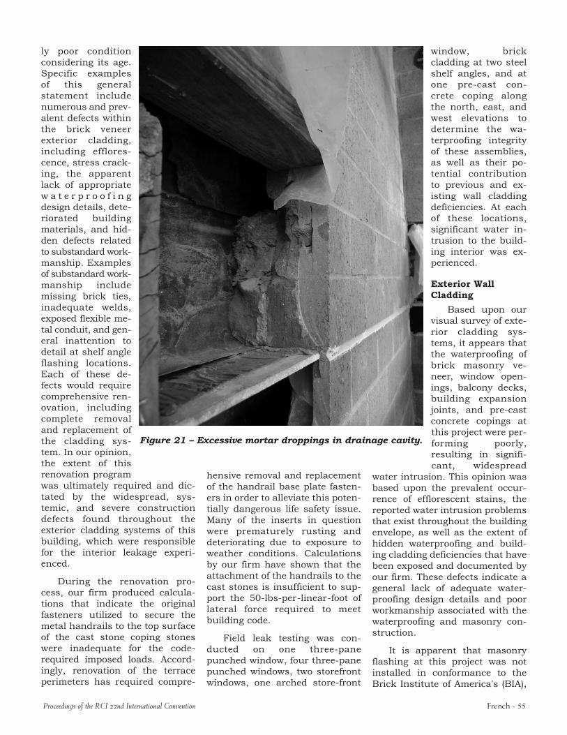
Figure 21 – Excessive mortar droppings in drainage cavity.
ly poor condition considering its age. Specific examples of this general statement include numerous and prevalent defects within the brick veneer exterior cladding, including efflorescence, stress cracking, the apparent lack of appropriate w a t e r p r o o f i n g design details, deteriorated building materials, and hidden defects related to substandard workmanship. Examples of substandard workmanship include missing brick ties, inadequate welds, exposed flexible metal conduit, and general inattention to detail at shelf angle flashing locations. Each of these defects would require comprehensive renovation, including complete removal and replacement of the cladding system. In our opinion, the extent of this renovation program was ultimately required and dictated by the widespread, systemic, and severe construction defects found throughout the exterior cladding systems of this building, which were responsible for the interior leakage experienced.
During the renovation process, our firm produced calculations that indicate the original fasteners utilized to secure the metal handrails to the top surface of the cast stone coping stones were inadequate for the coderequired imposed loads. Accordingly, renovation of the terrace perimeters has required compre
Proceedings of the RCI 22nd International Convention
hensive removal and replacement of the handrail base plate fasteners in order to alleviate this potentially dangerous life safety issue. Many of the inserts in question were prematurely rusting and deteriorating due to exposure to weather conditions. Calculations by our firm have shown that the attachment of the handrails to the cast stones is insufficient to support the 50lbsperlinearfoot of lateral force required to meet building code.
Field leak testing was conducted on one threepane punched window, four threepane punched windows, two storefront windows, one arched storefront
window, brick cladding at two steel shelf angles, and at one precast concrete coping along the north, east, and west elevations to determine the waterproofing integrity of these assemblies, as well as their potential contribution to previous and existing wall cladding deficiencies. At each of these locations, significant water intrusion to the building interior was experienced.
Exterior Wall Cladding
Based upon our visual survey of exterior cladding systems, it appears that the waterproofing of brick masonry veneer, window openings, balcony decks, building expansion joints, and precast concrete copings at this project were performing poorly, resulting in significant, widespread
water intrusion. This opinion was based upon the prevalent occurrence of efflorescent stains, the reported water intrusion problems that exist throughout the building envelope, as well as the extent of hidden waterproofing and building cladding deficiencies that have been exposed and documented by our firm. These defects indicate a general lack of adequate waterproofing design details and poor workmanship associated with the waterproofing and masonry construction.
It is apparent that masonry flashing at this project was not installed in conformance to the Brick Institute of America's (BIA),
French 55
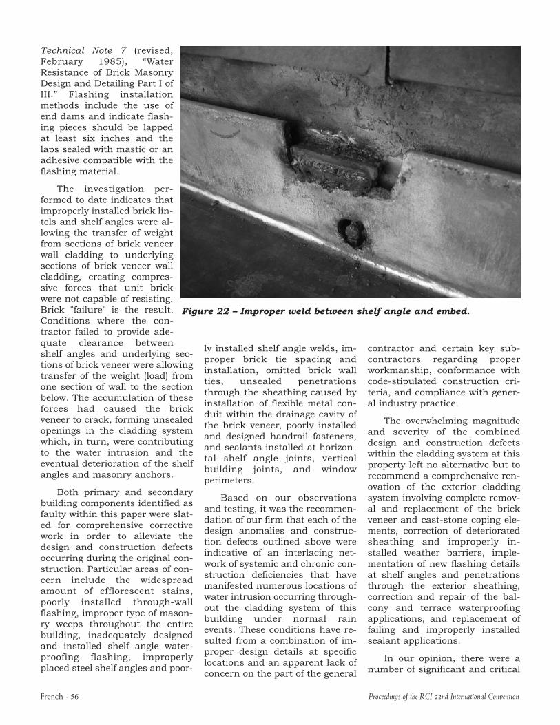
Figure 22 – Improper weld between shelf angle and embed.
Technical Note 7 (revised, February 1985), “Water Resistance of Brick Masonry Design and Detailing Part I of III.” Flashing installation methods include the use of end dams and indicate flashing pieces should be lapped at least six inches and the laps sealed with mastic or an adhesive compatible with the flashing material.
The investigation performed to date indicates that improperly installed brick lintels and shelf angles were allowing the transfer of weight from sections of brick veneer wall cladding to underlying sections of brick veneer wall cladding, creating compressive forces that unit brick were not capable of resisting. Brick "failure" is the result. Conditions where the contractor failed to provide adequate clearance between shelf angles and underlying sections of brick veneer were allowing transfer of the weight (load) from one section of wall to the section below. The accumulation of these forces had caused the brick veneer to crack, forming unsealed openings in the cladding system which, in turn, were contributing to the water intrusion and the eventual deterioration of the shelf angles and masonry anchors.
Both primary and secondary building components identified as faulty within this paper were slated for comprehensive corrective work in order to alleviate the design and construction defects occurring during the original construction. Particular areas of concern include the widespread amount of efflorescent stains, poorly installed throughwall flashing, improper type of masonry weeps throughout the entire building, inadequately designed and installed shelf angle waterproofing flashing, improperly placed steel shelf angles and poor
French 56
ly installed shelf angle welds, improper brick tie spacing and installation, omitted brick wall ties, unsealed penetrations through the sheathing caused by installation of flexible metal conduit within the drainage cavity of the brick veneer, poorly installed and designed handrail fasteners, and sealants installed at horizontal shelf angle joints, vertical building joints, and window perimeters.
Based on our observations and testing, it was the recommendation of our firm that each of the design anomalies and construction defects outlined above were indicative of an interlacing network of systemic and chronic construction deficiencies that have manifested numerous locations of water intrusion occurring throughout the cladding system of this building under normal rain events. These conditions have resulted from a combination of improper design details at specific locations and an apparent lack of concern on the part of the general
contractor and certain key subcontractors regarding proper workmanship, conformance with codestipulated construction criteria, and compliance with general industry practice.
The overwhelming magnitude and severity of the combined design and construction defects within the cladding system at this property left no alternative but to recommend a comprehensive renovation of the exterior cladding system involving complete removal and replacement of the brick veneer and caststone coping elements, correction of deteriorated sheathing and improperly installed weather barriers, implementation of new flashing details at shelf angles and penetrations through the exterior sheathing, correction and repair of the balcony and terrace waterproofing applications, and replacement of failing and improperly installed sealant applications.
In our opinion, there were a number of significant and critical
Proceedings of the RCI 22nd International Convention
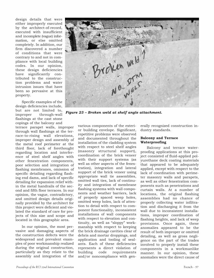
Figure 23 – Broken weld at shelf angle attachment.
design details that were either improperly executed by the architectofrecord, executed with insufficient and incomplete (vague) information, or else omitted completely. In addition, our firm discovered a number of conditions that were contrary to and not in compliance with local building codes. In our opinion, these design deficiencies have significantly contributed to the construction problems and water intrusion issues that have been so pervasive at this property.
Specific examples of the design deficiencies include, but are not limited to, improper throughwall flashings at the cast stone copings of the balcony and terrace parapet walls, improper through wall flashings at the terracetorising wall elevations, improper design and assembly of the metal roof perimeter at the third floor, lack of forethought regarding location and interference of steel shelf angles with other fenestration components, poor selection and integration of flashing membranes, omission of specific detailing regarding flashing end dams, and lack of specific detailing for expansion relief within the metal handrails of the second and fifth floor terraces. In our opinion, the vague, contradictory, and omitted design details originally provided by the architect for this project were deficient and violated the standard of care for projects of this size and scope and located in this geographic area.
In our opinion, the most pervasive and damaging aspects of the construction defects were the widespread and prevalent examples of poor workmanship realized during the original construction, particularly as they relate to the assembly and integration of the
Proceedings of the RCI 22nd International Convention
various components of the exterior building envelope. Significant, repetitive problems were observed and documented throughout the installation of the cladding system with respect to steel shelf angles (masonry structural support), coordination of the brick veneer with their support systems (as well as other aspects of the fenestration), integration and lateral support of the brick veneer using appropriate wall tie assemblies, omitted wall ties, lack of continuity and integration of membrane flashing systems with wall components and weather barriers, lack of properly spaced weep holes, omitted weep holes, lack of attention to detail with respect to component functionality, inconsistent installations of wall components with respect to elevation and continuity, as well as “sloppy” workmanship with respect to keeping the brick drainage cavities clear of debris and mortar droppings, and application and tooling of sealants. Each of these deficiencies represents a direct violation of building code requirements and/or noncompliance with gen
erally recognized construction industry standards.
Balcony and Terrace Waterproofing
Balcony and terrace waterproofing applications at this project consisted of fluidapplied polyurethane deck coating materials that appeared to be adequately applied, except with respect to the lack of coordination with perimeter masonry walls and parapets, as well as other fenestration components such as penetrations and curtain walls. At a number of locations, the original flashing assemblies had no chance of properly collecting water infiltration and discharging it from the wall due to inconsistent installations, improper coordination of flashing heights, and lack of weep provisions. Once again, these anomalies appeared to be the result of both improper or omitted detailing, as well as gross negligence on the part of the trades involved to properly install these components in a workmanlike manner. In our opinion, these anomalies were the direct cause of
French 57
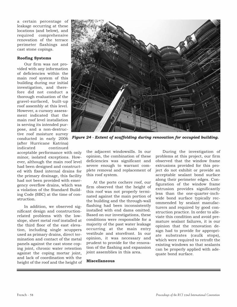
Figure 24 - Extent of scaffolding during renovation for occupied building.
a certain percentage of leakage occurring at these locations (and below), and required comprehensive renovation of the terrace perimeter flashings and cast stone copings.
Roofing Systems
Our firm was not provided with any information of deficiencies within the main roof system of this building during our initial investigation, and therefore did not conduct a thorough evaluation of the gravelsurfaced, builtup roof assembly at this level. However, a cursory assessment indicated that the main roof level installation is serving its intended purpose, and a nondestructive roof moisture survey conducted in early 2006 (after Hurricane Katrina) indicated continued acceptable performance with only minor, isolated exceptions. However, although the main roof level had been designed and constructed with fixed internal drains for the primary drainage, this facility had not been provided with emergency overflow drains, which was a violation of the Standard Building Code (SBC) at the time of construction.
In addition, we observed significant design and constructionrelated problems with the lowslope, sheet metal roof installed at the third floor of the east elevation, including single scuppers used as primary drains, direct termination and contact of the metal panels against the cast stone coping joint, chronic water retention against the coping mortar joint, and lack of coordination with the height of the roof and the height of
the adjacent windowsills. In our opinion, the combination of these deficiencies was significant and severe enough to warrant complete removal and replacement of this roof system.
At the porte cochere roof, our firm observed that the height of this roof was not properly terminated against the main portion of the building and the throughwall flashing had been inconsistently installed with end dams omitted. Based on our investigations, these conditions were responsible for a majority of the past water leakage occurring at the main entry vestibule and storefront. In our opinion, it was necessary and prudent to provide for the renovation of the flashing and expansion joint assemblies in this area.
Miscellaneous
During the investigation of problems at this project, our firm observed that the window frame extrusions provided for this project do not exhibit or provide an acceptable sealant bond surface along their perimeter edges. Configuration of the window frame extrusion provides significantly less than the onequarterinchwide bond surface typically recommended by sealant manufacturers and required by good construction practice. In order to alleviate this condition and avoid premature sealant failures, it is our opinion that the renovation design had to provide for appropriate substrates (caulk stops), which were required to retrofit the existing windows so that sealants can be properly applied with adequate bond surface.
French 58 Proceedings of the RCI 22nd International Convention