domestic product failures – case studies · materials engineering ... death directly attributable...
TRANSCRIPT

Engineering Failure Analysis 12 (2005) 784–807
www.elsevier.com/locate/engfailanal
Domestic product failures – Case studies
C. Gagg *
Materials Engineering Department, The Open University, Milton Keynes, Buckinghamshire, Walton Hall MK7 6AA, UK
Received 12 July 2004; accepted 12 December 2004
Available online 13 April 2005
Abstract
Every year in the UK more than 4000 people die in accidents in and around the home and nearly three million turn
up at accident and emergency departments seeking treatment. Intrinsic in this number are many incidents of injury or
death directly attributable to poor product design or manufacture of domestic products. In and around the home, com-
modities that dominate so much of every-day life are becoming more numerous and complex and could be mooted as an
argument for such dire statistics. Moreover, society in general is becoming more litigious. These converging trends are
responsible for an increasing significance of product liability. When property is damaged, personal injury sustained or
loss of life occurs there is an understandable need to determine where any fault may lie. The forensic (or failure) engi-
neer will glean relevant information through meticulous investigation and a reverse engineering process. Reconstructing
the failure will uncover any inherent defect in product design, manufacturing, incorrect installation or maintenance.
However, product failure can also be attributable to careless use or abuse by the individual, rather than to any specific
defect or design shortcoming being inherent within a product. Ultimately the outcome of any investigation will be a
sound finding and a conclusion that clearly describes what happened and why. To illustrate typical failure modes that
are currently emerging in the home-based UK market, a range of domestic product failures are presented from the
author�s forensic casebook.
� 2005 Elsevier Ltd. All rights reserved.
Keywords: Domestic products; Failure; Reverse engineering; case studies
1. Introduction
Road accident statistics in the UK make alarming reading, with 3400 deaths, 38,000 serious injuries and
279,000 slight injuries in the year 2000 alone [1]. However, these figures pale when comparing statistics for
accidents in and around the home and garden. Every year in the UK 4300 people die, 168,300 suffer serious
1350-6307/$ - see front matter � 2005 Elsevier Ltd. All rights reserved.
doi:10.1016/j.engfailanal.2004.12.004
* Tel.: +44 1908 652 869; fax: +44 1909 653 858.
E-mail address: [email protected].

C. Gagg / Engineering Failure Analysis 12 (2005) 784–807 785
injury and approximately 2.9 million attend accident and emergency units for injuries sustained in home
accidents [2–4]. Inherent within this number there are many incidents of injury or death that can be directly
attributed to poor product design or manufacture. The relationship between unsafe products and injury is
unclear, but it has been suggested that the proportion could be as high as one in four of all home and leisure
accidents being attributed to faulty products [5]. With increased UK interest in home improvements (DIY)and leisure time pursuits, it is not unreasonable to assume that there will be little or no improvement of such
statistics in the short term.
Manufacturers generally operate rigorous quality control procedures at the manufacturing stage. It is,
therefore, unusual for faulty products to enter service. However, on occasion faulty goods do manage to
slip through the most rigorous of checks and enter service as domestic equipment in people�s homes or
as apparatus for sporting and leisure pursuits. Once in everyday use these products can contribute to
and sometimes cause accidents, usually on the first occasion they are exposed to a heavy loading. Human
nature being what it is, the injured party will look for some blame for their misadventure, more often thannot resort to litigation for compensation.
The picture is further complicated by an area of product reliability that is causing increased concern – that
of the imported domestic device, sporting goods or hand tools. A survey carried out by the Suffolk Trading
Standards Department [6–8] found around 10% of imported products checked by them, were unsafe.
In this review, the cases presented will follow the failure of domestic goods, hand tools and sporting
equipment from the author�s forensic casebook. However, it must be emphasised that individual failures
can and often do emanate from careless use or abuse by the individual, rather than be attributable to
any specific defects that may be inbuilt within a product. This is adequately illustrated by the first case –a domestic step-ladder accident.
2. Case 1: step ladders
Statistics show that every year, many people fall from steps or ladders causing on average 50 deaths in
the UK, 1000 serious injuries and 40,000 hospital visits. The Association of British Insurers has stated that
612 Billion a year is lost in the UK through accidents, and of these 25% are as a result of falls from height.Step-ladders provide a free-standing means of access, but they necessitate careful use. They are not de-
signed for any degree of side loading and are relatively easily overturned. The most common cause of acci-
dent stems from over-reaching, causing the steps to topple sideways. However, human nature being what it
is, the individual will always look for someone or something else to blame for any misfortune. It is now
commonplace for the ladder accident �victim� to seek redress from the manufacturer, retail outlet or the
Courts of Law. However, from experience it can be safely stated that almost all step-ladder accidents
are caused by human error, not by unexpectedly �collapsing� or otherwise failing from an inherent fault.
A typical case that will illustrate characteristic step-ladder accidents concerned a middle-aged man whowas standing on the top platform of a four tread step-ladder. He was reaching into a cupboard, located
above his bedroom door, to retrieve suitcases for a forthcoming holiday. He had almost finished the task,
and was stretching to get to the last case at the back of the cupboard. Suddenly and without warning the
right leg was alleged to have collapsed, throwing the man to the ground. He sustained a leg fracture which
entailed accident and emergency treatment, with resultant loss of earnings and his holiday. He immediately
instigated legal proceedings against the manufacturer for marketing a product that was unfit for service.
The types of alloy used for the manufacture of a lightweight step/extension ladder should have a tensile
strength in the range 200–310 MPa (BS:2037:1994) As hardness of an aluminium alloy will give a directindication of tensile strength, results of Vickers hardness testing of the sample produced values between
85.7 and 89.6 Hv, equating to a tensile strength of 274–287 MPa. Therefore, the material from which the
legs were made conformed to the requirements of alloys set down in BS:2037 and fell within the range

Fig. 1. Lightweight aluminium step ladder in question. Note: inward bend on both stiles.
786 C. Gagg / Engineering Failure Analysis 12 (2005) 784–807
of specified strength. There was no evidence to suggest that the stiles were inherently weak or likely to fail.
The construction of this ladder conformed to BS:2037 1994, so the cause of failure in this instance must
have been due to the load applied at the time of the collapse.
As loads acting on the treads and platform would tend to splay the legs outwards, it would be reasonableto assume that the type of bending observed in this failure (i.e., both legs bent inwards) would reflect a de-
gree of misuse (Fig. 1).
An explanation for the features observed is that the steps were sound up to the moment of an incident
such as over reaching, which caused the step-ladder to topple sideways. Subsequently, the right leg was sub-
jected to a shock loading whilst in a near horizontal position to the ground (Fig. 2) This shock loading was
almost certainly generated by a falling body, causing severe damage to the right stile and at the same time,
minor damage to the left stile of the step-ladder. There are no grounds to support any allegation of material
or manufacturing fault or that the ladder was unfit for service immediately prior to the accident. Therefore,it can be said with confidence that an incident such as described was the cause of the damage rather than the
damage being the cause of this incident.
3. Case 2: club hammer
A workman was using a club hammer to break up old reinforced concrete garage panels when a sliver
flew from the head, causing an eye injury to the man. It was surgically removed sometime later at a localhospital. The hammer bore no manufacturers name, or British Standard kitemark. It was an imported tool
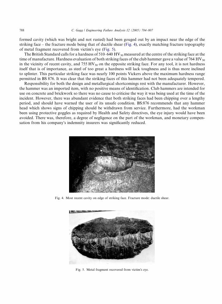
and had the general look of a well used item (Fig. 3).
The striking faces were square edged, with no evidence of ever having any 45� chamfering at the time of
manufacture, as required by BS876:1995; Hand Hammers. The purpose of a chamfer is to minimise the risk
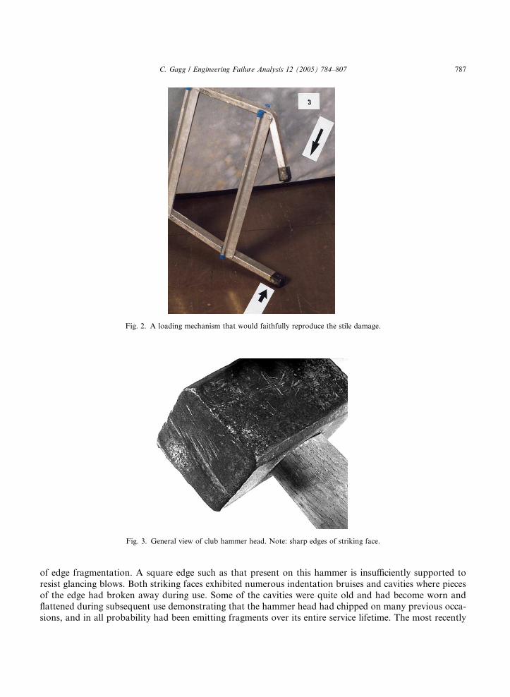
Fig. 3. General view of club hammer head. Note: sharp edges of striking face.
Fig. 2. A loading mechanism that would faithfully reproduce the stile damage.
C. Gagg / Engineering Failure Analysis 12 (2005) 784–807 787
of edge fragmentation. A square edge such as that present on this hammer is insufficiently supported to
resist glancing blows. Both striking faces exhibited numerous indentation bruises and cavities where pieces
of the edge had broken away during use. Some of the cavities were quite old and had become worn and
flattened during subsequent use demonstrating that the hammer head had chipped on many previous occa-
sions, and in all probability had been emitting fragments over its entire service lifetime. The most recently
788 C. Gagg / Engineering Failure Analysis 12 (2005) 784–807
formed cavity (which was bright and not rusted) had been gouged out by an impact near the edge of the
striking face – the fracture mode being that of ductile shear (Fig. 4), exactly matching fracture topography
of metal fragment recovered from victim�s eye (Fig. 5).
The British Standard calls for a hardness of 510–640 HV30measured at the centre of the striking face at the
time of manufacture. Hardness evaluation of both striking faces of the club hammer gave a value of 764 HV30
in the vicinity of recent cavity, and 755 HV30 on the opposite striking face. For any tool, it is not hardness
itself that is of importance, as steel of too great a hardness will lack toughness and is thus more inclined
to splinter. This particular striking face was nearly 100 points Vickers above the maximum hardness range
permitted in BS 876. It was clear that the striking faces of this hammer had not been adequately tempered.
Responsibility for both the design and metallurgical shortcomings rest with the manufacturer. However,
the hammer was an imported item, with no positive means of identification. Club hammers are intended for
use on concrete and brickwork so there was no cause to criticise the way it was being used at the time of the
incident. However, there was abundant evidence that both striking faces had been chipping over a lengthyperiod, and should have warned the user of its unsafe condition. BS:876 recommends that any hammer
head which shows signs of chipping should be withdrawn from service. Furthermore, had the workman
been using protective goggles as required by Health and Safety directives, the eye injury would have been
avoided. There was, therefore, a degree of negligence on the part of the workman, and monetary compen-
sation from his company�s indemnity insurers was significantly reduced.
Fig. 4. Most recent cavity on edge of striking face. Fracture mode: ductile shear.
Fig. 5. Metal fragment recovered from victim�s eye.

C. Gagg / Engineering Failure Analysis 12 (2005) 784–807 789
4. Case 3: crankpin from a bicycle
A 20-year-old cyclist was pedalling up an incline when the left pedal broke without warning, causing the
rider to be thrown into a ditch causing head, leg and arm injuries. The cycle was some 3 years old, had been
properly maintained and had not been involved in any previous accident. The injured rider was a keen cy-clist and had used the machine regularly, covering 35–50 miles most weekends and 8–10 miles most eve-
nings. All maintenance had been carried out by the retailer from whom the cycle had been purchased.
At the time of his accident, the cyclist weighed 9 st 12 lbs and was 5 0900 tall. He was absolutely certain
the left pedal had come off while he was standing on it to keep his speed up the incline. Furthermore, there
was no kerb at the side of the road which might have caught against the machine whilst he was riding.
The broken left pedal was part of a �cotterless� crank (Fig. 6a), a design which is located onto a square
section on the end of the crankpin and held by a screw. Light abrasion marks were noticed near the top of
the crank, but were of recent origin and consistent with the metal having contacted the road surface after ithad broken off. No damage could be found on the crank or the pedal that would suggest any kind of impact
of sufficient magnitude to fracture the crankpin. Both pedals were rigid and completely undamaged apart
from light abrasions on the outside of the spindle caps, commensurate with 3 years service. Microscopic
study of the ball bearing tracks on the crankpin revealed no evidence of indentation, such as would have
occurred if any substantial impact force had been transmitted from the pedal crank to the frame bearings
(Fig. 6b). Any major impacting force transmitted from the pedal or lower part of the crank to the crankpin
would have been expected to bend the crank out of line, but there was no evidence of any such damage. It
was concluded that the crankpin cannot have broken instantaneously as a result of some externally appliedmechanical overload force.
Two features were significant; first, there was a rim approximately 1 mm deep extending round the
periphery which showed that the component had been case hardened. This is a conventional method of treat-
ing cycle parts to achieve wear resistance and strength, so there is nothing unusual about this discontinuity
in the fracture surface. The second feature was significant in relation to the mode of failure and is revealed by
the path the fracture takes across the section. In Fig. 7 it can be seen that the fracture is at 90� to the axis of
the crankpin on the sides of the square adjacent to the corner identified �A�, whereas it follows helical pathsterminating in a cusp at the opposite corner marked �B�. this is interpreted as a progressive fracture whichstarted along the edge to the right of �A� and progressed in a series of jumps to finish at the corner �B�. Therehad been a significant change in the stressing system when the fracture reached the midway position, where
the path changes from 90� to the surface to the helical route, and this was associated with the crack front
bending forces which had initiated the cracking and directed its path up to this stage.
Fig. 6. Broken end of crank. Arrow points to region where cracking initiated. Note helical cusp at opposite side, where fracture
terminated (a); closer view of crankpin. Note the absence of any damage to the ball tracks (arrowed, bright areas at raised shoulders)
which would have been produced by major impact (b).

Fig. 7. View of fracture, with region of initiation marked �A� and cusp where helical fractures terminated marked �B�.
790 C. Gagg / Engineering Failure Analysis 12 (2005) 784–807
There was no evidence to suggest this failure was related in any way to the manner in which the cycle had
been maintained or that it was caused by mechanical abuse or a result of accidental or impact damage. The
crankpin had failed by a fatigue mechanism. A crack had initiated along one edge of the square and had
been spreading across the section over a period of time until it had reached the stage when all that was re-
quired to break it completely was a slightly higher than average force on the pedal, but one at a level that
had been withstood satisfactorily on many previous occasions before the cracking had spread so far. The
circumstances at the time of the accident are, therefore, of little significance, since failure was inevitablesooner or later; all that was required as an extra hard push on the pedal. The path indicated the pedal
was near the bottom of its travel when it finally broke off and this would have caused the rider to fall to
the left hand side of the machine. There would have been no warning or externally visible sign of the
impending failure. The fatigue crack would have appeared as a fine, hairline mark on the surface, but this
would not have been visible without removing the crank and, even then, it would have required someone
with specialist knowledge to recognise its significance.
Failure of a crankpin such as described is unusual and suggests there was some kind of weakness stemming
from material or manufacturing fault to cause failure. Accordingly the broken end was removed from thepedal crank and sectioned so that metallographic examination and microhardness tests could be carried out.
The polished longitudinal section was scanned for possible alloying elements on a scanning electron
microscope using EDAX technique. The results indicated the material was a plain carbon steel which con-
tained no intentional alloying addition, the principal elements reported being:
Silicon
0.2% Chromium 0.04%Manganese
0.73% Nickel 0.53%Molybdenum
0.16%Longitudinal and transverse sections were prepared, the former being selected so as to include both the
initiating and the terminating regions of the fracture. Etched microsections, illustrated in Figs. 8–10, re-
vealed a structural abnormality resulting from the case hardening heat treatment process. Case hardening
is commonly applied to develop wear and fatigue resistance in engineering components and is widely usedfor cycle parts. It is the high hardness of the case which gives the wear resistance and the martensitic trans-
formation produces compressive stress in the case which generally improves the fatigue resistance.
Fig. 8(a) shows an etched longitudinal section of the entire cross-section of the crankpin within 4–5 mm
of the fracture and Fig. 8(b) the same specimen at the fractured edge. Features normally observed in a cor-

C. Gagg / Engineering Failure Analysis 12 (2005) 784–807 791
rectly case hardened component would comprise the martesitic case and a mixed structure of ferrite and low
carbon martensite in the core (which would extend to the screw threads of the centre hole in the crankpin).
The depth of the case is 0.6 mm in this section. Of particular significance is the difference between the frac-
tured edges on opposite sides of the crankpin; that in Fig. 8(b), where the fracture initiated, is fairly smooth
and featureless whereas that of the opposite edge, where it terminated, is rough and irregular. These fea-tures confirm that the failure had occurred in a fatigue mode.
Fig. 8(a) and (b), the region where the fracture initiated, exhibit similar microstructures to the above,
except for one very significant feature of the case, which in these photomicrographs, is seen along the
top of the photographs. In Fig. 8(a) a mottled band can be seen parallel with and just below the outer sur-
face and this continues into the fracture, Fig. 8(b), though, becoming slightly less distinct. This same region
is illustrated at higher magnifications in Fig. 9. The dark areas are �pearlite�, which should not be present in
a correctly hardened case, and reveal that the quenching rate at this surface was too slow when the crankpin
was quenched to harden the carburised case. In the lower illustration of Fig. 9 the magnification has beenincreased to show the presence of cementite network outlining grain boundaries between the pearlite col-
onies. At the fracture surface these have opened out into crack and it is considered these were the initiation
sites of the fatigue cracking.
A transverse section taken 8 mm further away from the fracture, towards the pedal end, is illustrated in
Fig. 10. This shows the outer part of the case to be completely pearlitic, indicating the quenching rate was
even slower in this region than closer to the fracture. Beneath this mottled structure at the outside is the
featureless, white etching band of martensite, which merges into the duplex structure of the core towards
the bottom of the photograph.Vikers hardness tests were undertaken on the martensitic and pearlite bands. Values were in the range of
900–950 and 780–820 Hv, respectively. A line survey consisting of 12 equal intercepts from the surface to
1.5 mm into the core, carried out on the section illustrated in Fig. 8, produced a gradient which fell steeply
from 950 Hv at the extreme surface to 802 Hv at 0.1 mm into the case, thereafter rose to 940 Hv again at
0.3 mm and remained at this level to 0.6 mm, before gradually falling to 434 Hv at 1.5 mm in the core. The
softer zone in the case corresponded to the position of the band of pearlite appearing in Fig. 8.
The conclusions to metallurgical results revealed that the steel from which the crankpin was made was
of suitable quality for case hardening by carburising, but the structure produced by quenching was notuniform throughout the case, inasmuch that the cooling rate during the quench had not been sufficiently
Fig. 8. Etched cross-section extending from outer surface to threaded hole, taken a short distance from fracture initiation (a).
Magnification 29·: the right hand micrograph is of the same section as (a) but includes the fracture surface at the right side, and at
slightly higher magnification (b). Magnification 36·.
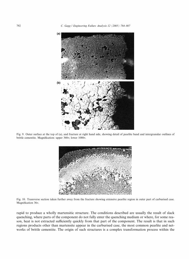
Fig. 10. Transverse section taken further away from the fracture showing extensive pearlite region in outer part of carburised case.
Magnification 36·.
Fig. 9. Outer surface at the top of (a), and fracture at right hand side, showing detail of pearlite band and intergranular outlines of
brittle cementite. Magnification: upper 360·; lower 1080·.
792 C. Gagg / Engineering Failure Analysis 12 (2005) 784–807
rapid to produce a wholly martensitic structure. The conditions described are usually the result of slack
quenching, where parts of the component do not fully enter the quenching medium or where, for some rea-son, heat is not extracted sufficiently quickly from that part of the component. The result is that in such
regions products other than martensite appear in the carburised case, the most common pearlite and net-
works of brittle cementite. The origin of such structures is a complex transformation process within the

C. Gagg / Engineering Failure Analysis 12 (2005) 784–807 793
steel and an additional factor is slight decarburisation which tends to occur during the second stage of the
case hardening process.
As a consequence of the incorrect microstructure, brittle intergranular networks of cementite were pro-
duced in the case and these eventually developed into fatigue cracks in service. An additional factor would
be an uneven distribution of internal compressive stress in the surface layers. The formation of pearlite re-duced the volume increase associated with the transformation, with the consequence that the case was less
able to resist the service loadings applied to the crankpin. Additionally, the intergranular networks of
cementite could develop into cracks under high loadings. Both of these mechanical effects would have sub-
stantially reduced the fatigue resistance of this part of the crankpin.
The metallurgical fault described above was introduced at the time of manufacture and the cracking
most probably initiated soon after the cycle was first ridden. Shortly before the pedal crank finally broke
away the crack had extended only half way across the crankpin section, but the final, mainly torsional
development had been rapid and could easily have occurred during the one ride on the day of the accident.However, the fracture does not exhibit the usual appearance of a long developing fatigue failure and it
could be that the cracks did not start to grow appreciably until the cyclist had developed the muscular
strength and technique which enabled him to apply sufficient force to the pedals. It is interesting to note
that the cracking initiated on the surface of the crankpin that only came under high stress towards the bot-
tom of the pedal�s rotation. In this respect it is significant that the cyclist stated he was standing on the ped-
als to gain speed up a slight incline when the pedal broke away, which is the same action that would have
applied the forces necessary to initiate the cracking earlier in the crankpin�s service. No blame for this acci-
dent could be attached to the cyclist, and there was no evidence that he did anything more than ride thecycle normally and have it maintained by the retailer. The crankpin was not cracked when the cycle was
purchased and it would have required specialists skills to have detected the developing fatigue crack shortly
before the final failure and, even then, only if the pedal cranks had been removed and the exposed parts of
the crankpin carefully cleaned and inspected. Furthermore, the defective structure in the crankpin was
localised within the hardened case and could only have been detected by destructive metallurgical exami-
nation such as described above.
5. Case 4: failed guard from a hand grinder
A guard that was providing protection around the cutting disc of a heavy-duty industrial angle grinder,
failed in service. The failure and instantaneous jamming caused the disc to burst which in turn inflicted se-
vere injury to the legs and arm of the operative.
The guard in question was an integral safety feature mounted on the grinder. It had been fabricated by
cold forming sheet steel stock, followed by a spot welding operation to join three component parts into a
safety guard for use around the cutting disc of a hand grinder (Fig. 11(a)).The component parts comprised a back and front section along with a clamping strap, the assembled
guard having an approximate diameter of some 24.5 cm, height of 12 cm and maximum depth of 3.5 cm.
A black resistant powder coating had been applied as a decorative finish.
Simple visual observation of the product in question revealed greatly differing bend radii, with an abso-
lute minimum being observed at the point of fracture. Measurement revealed the larger bend (point 1 on
Fig. 11(b)) had an internal radius of 4 mm, whereas the internal radius at the point of fracture (point 2 on
Photograph 1b) was approximately 1 mm. Material gauge (thickness) was �2.0 mm, this being a direct met-
ric replacement for the Imperial 14 SWG.Under magnification, the fracture was found to have initiated at the site of the smallest bend radius –
more specifically, on the tensile surface of this radius. Closer inspection of the fracture surface revealed
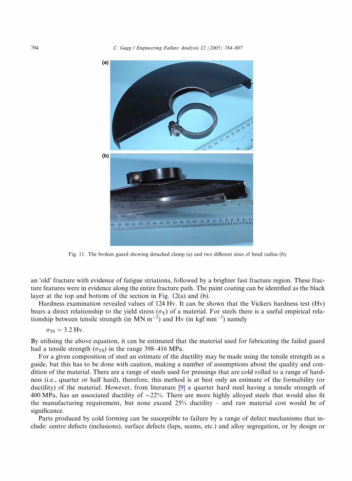
Fig. 11. The broken guard showing detached clamp (a) and two different sizes of bend radius (b).
794 C. Gagg / Engineering Failure Analysis 12 (2005) 784–807
an �old� fracture with evidence of fatigue striations, followed by a brighter fast fracture region. These frac-
ture features were in evidence along the entire fracture path. The paint coating can be identified as the black
layer at the top and bottom of the section in Fig. 12(a) and (b).Hardness examination revealed values of 124 Hv. It can be shown that the Vickers hardness test (Hv)
bears a direct relationship to the yield stress (rY) of a material. For steels there is a useful empirical rela-
tionship between tensile strength (in MN m�2) and Hv (in kgf mm�2) namely
rTS ¼ 3:2 Hv:
By utilising the above equation, it can be estimated that the material used for fabricating the failed guard
had a tensile strength (rTS) in the range 398–416 MPa.For a given composition of steel an estimate of the ductility may be made using the tensile strength as a
guide, but this has to be done with caution, making a number of assumptions about the quality and con-
dition of the material. There are a range of steels used for pressings that are cold rolled to a range of hard-
ness (i.e., quarter or half hard), therefore, this method is at best only an estimate of the formability (or
ductility) of the material. However, from literature [9] a quarter hard steel having a tensile strength of
400 MPa, has an associated ductility of �22%. There are more highly alloyed steels that would also fit
the manufacturing requirement, but none exceed 25% ductility – and raw material cost would be of
significance.Parts produced by cold forming can be susceptible to failure by a range of defect mechanisms that in-
clude: centre defects (inclusions), surface defects (laps, seams, etc.) and alloy segregation, or by design or

Fig. 12. Fracture surface showing older crack with fatigue striations as dark area at top, with newer brighter fast fracture region at
bottom.
C. Gagg / Engineering Failure Analysis 12 (2005) 784–807 795
manufacturing shortcomings such as: grain deformation, corner thinning, strain hardening, orange-peel de-
fect, lack of generous fillets, or sharp radii. Microstructural observation revealed a clean (minimal inclu-
sions) structure that did not exhibit a highly directional grain shape. Therefore, attention became
focused on design or manufacturing for the answer to this failure.
Cold forming must be performed within the boundary set by the material and tooling used. It is obvi-ously essential to exceed the strength or elastic limits of a given material during any deformation process.
Care must, therefore, be taken to ensure that material specifications are accurately and realistically specified
in order to provide a product that will fulfil desired expectations. Conversely, design of tooling should be
such that the process operation does not exceed any mechanical capability of the material in use. Designing
a cold-formed process that operates at the extreme limit of any material will lead to an unacceptably high
level of parts failure due to inevitable variations that can occur between batches of stock material.
Knowing that the maximum ductility a steel stock material could be expected to exhibit is <25% and, in
any cold forming operation, it is ductility (strain to failure) that is paramount. Simple engineering calcula-tions can, therefore, be employed to assess strains associated with the bending operation on the artefact in
question. Results of such calculations are presented at the end of this case study and show that maximum
bending strains for the large (unbroken) radius observed on the guard, were approximately 20%. Although
at the high end of the material performance scale, the strains generated are within the material specification.
However, when considering the bend formed at the smaller (broken) radius, calculations show that bending
strains are up to some 50% – two times that of the ductility of the material.
At the point of manufacture the operation of bending alone had caused a crack in the outer (tensile) face
of the bend. This would almost certainly have gone unnoticed and subsequent paint finishing would with-out doubt hide any visual evidence of the defect. Powder coating paint system was such that ingress into
any existing defect would not be expected, i.e., it would �bridge� any pre-existing crack.
Having entered service with a pre-existing crack, it was only a matter of time before vibration forces
(exacerbated by the shearing action of the clamping strap upon the crack defect) propagated the crack
to final failure, the actual failure mode being one of low cycle fatigue initiated by the pre-existence of a
crack that had been introduced during manufacture. Observation of the fracture surface gave confidence
to these findings. It would be expected that similar failures of this product would occur. The material simply
�ran out� of ductility during the forming operation. As such the failure is directly attributable to a manu-

796 C. Gagg / Engineering Failure Analysis 12 (2005) 784–807
facturing fault where the crack that led directly to component failure, had been ‘‘manufactured in’’. When
considering litigation, it can confidently be said that failure of this type would most certainly be foreseeable.
Strain calculations [9,10]
From [2]: Longitudinal strain in fibre
ex ¼ðRþ yÞdh� Rdh
Rdh:
Therefore,
ex ¼yR;
where y is the distance from neutral axis and R is the radius of curvature of neutral axis for this particular
configuration, y = ymax is the distance to outer fibre.
1.0 mmy max
For the large radius at point (A) on figure 11b:2 mm R = 4.0 mm+1.0 mm = 5.0 mm
‘R’ and, for the smaller (broken) radius, (B)on figure 11b:
R = 1.0 mm+1.0 mm = 2.0 mm
neutral axies
At position (A) on Photograph 2, the inside radius of bend was 4 mm; therefore, strain at the outsidesurface was
ex ¼ymax
R¼ 1:0� 10�3
5:0� 10�3¼ 0:20 or 20% strain:
At position (B) on Fig. 11(b), the inside radius of bend was 1 mm, and here the strain at the outer material
surface was
ex ¼ðRþ yÞdh� Rdh
Rdh¼ 1:0� 10�3
2:0� 10�3¼ 0:50 or 50% strain:
6. Case 5: cistern handle failure
A toilet cistern-flushing handle failed after being in service for a period in excess of 5 years. The handle
and boss had been manufactured in zinc by a pressure die casting route and subsequently chromium plated
for aesthetic reasons. The product was of a type that had been mass-produced for the cheaper end of
the market, and just prior to failure a somewhat ample female had been attempting to flush her toilet by
pushing down heavily onto the handle. Lime-scale build-up had been causing increased difficulty with
her ability to flush her cistern by use of light pressure on the handle. At the instant of failure, the femalewas giving a heavy push, using the heel of her right hand and leaning down heavily. The handle broke and
C. Gagg / Engineering Failure Analysis 12 (2005) 784–807 797
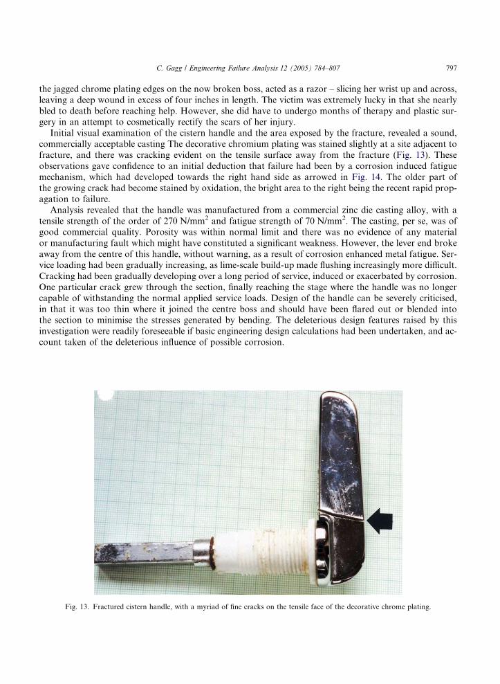
the jagged chrome plating edges on the now broken boss, acted as a razor – slicing her wrist up and across,
leaving a deep wound in excess of four inches in length. The victim was extremely lucky in that she nearly
bled to death before reaching help. However, she did have to undergo months of therapy and plastic sur-
gery in an attempt to cosmetically rectify the scars of her injury.
Initial visual examination of the cistern handle and the area exposed by the fracture, revealed a sound,commercially acceptable casting The decorative chromium plating was stained slightly at a site adjacent to
fracture, and there was cracking evident on the tensile surface away from the fracture (Fig. 13). These
observations gave confidence to an initial deduction that failure had been by a corrosion induced fatigue
mechanism, which had developed towards the right hand side as arrowed in Fig. 14. The older part of
the growing crack had become stained by oxidation, the bright area to the right being the recent rapid prop-
agation to failure.
Analysis revealed that the handle was manufactured from a commercial zinc die casting alloy, with a
tensile strength of the order of 270 N/mm2 and fatigue strength of 70 N/mm2. The casting, per se, was ofgood commercial quality. Porosity was within normal limit and there was no evidence of any material
or manufacturing fault which might have constituted a significant weakness. However, the lever end broke
away from the centre of this handle, without warning, as a result of corrosion enhanced metal fatigue. Ser-
vice loading had been gradually increasing, as lime-scale build-up made flushing increasingly more difficult.
Cracking had been gradually developing over a long period of service, induced or exacerbated by corrosion.
One particular crack grew through the section, finally reaching the stage where the handle was no longer
capable of withstanding the normal applied service loads. Design of the handle can be severely criticised,
in that it was too thin where it joined the centre boss and should have been flared out or blended intothe section to minimise the stresses generated by bending. The deleterious design features raised by this
investigation were readily foreseeable if basic engineering design calculations had been undertaken, and ac-
count taken of the deleterious influence of possible corrosion.
Fig. 13. Fractured cistern handle, with a myriad of fine cracks on the tensile face of the decorative chrome plating.

Fig. 14. Fracture surface, showing oxidation staining of older part of the fracture, with the bright (recent) rapid growth to failure on
the right.
Fig. 15. Fractured end of handle, showing additional cracking (arrowed) and corrosion on external nickel plating.
798 C. Gagg / Engineering Failure Analysis 12 (2005) 784–807

Fig. 16. Fracture surface of the handle, showing corrosion staining on inside of pivot hole.
C. Gagg / Engineering Failure Analysis 12 (2005) 784–807 799
6.1. Cause of window handle failure
A similar failure came to light when a lady in a wheelchair suffered bad cuts to her hand and arm whenclosing her window. The handle mechanism was exceptionally stiff, requiring a good deal of effort to close it
properly. At the instant of failure, the lady was giving the handle a forceful tug, when the handle gave way,
causing her to lose balance and fall forward in her wheel chair. In trying to save herself from falling out of
the chair, her hand went through the glass, causing extensive injury to her hand and arm.
Again, the handle was a plated zinc die casting, and observation showed corrosion and cracking away
from the fracture site (Fig. 15). Corrosion staining was also present on the inside of the pivot hole (Fig. 16).
The fracture surface contained striations, indicative of fatigue. Therefore, the failure mechanism was also
one of corrosion assisted fatigue. The design of handle could not be criticised, in that its casting quality,plating and section were within limit. However, observation of the lock mechanism and hinges showed that
their had been little or no lubricant applied to relevant parts, causing increasing difficulty in both opening
and closing the window unit. This continually increasing service loading leading to ultimate failure – en-
hanced and assisted by the influence of corrosion. As the housing unit was owned and run by a local council
for disabled tenants, they were held liable for injury, and made a settlement of £8500.
7. Case 6: failure of skateboard truck bracket
A young man had an accident whilst riding his skateboard through a purpose built pipe. The board itself
was supposedly of a professional variety, fully capable of sustaining loading generated by the rider under-
taking high impact stunts and jumps. He had just completed a jumping manoeuvre when the aluminium

800 C. Gagg / Engineering Failure Analysis 12 (2005) 784–807
truck bracket on his board broke under landing shock. The ensuing crash left the rider with a broken right
leg, along with wrist and arm injuries.
In a post accident statement, the injured rider stated that the skateboard had only been in use for
approximately three weeks prior to failure. However, simple observation revealed pronounced scuffing
of both the leading and trailing edges of the deck, indicative of a well used artefact. Nevertheless, other thanthe fractured axle truck, there was no indication of abuse or lack of maintenance of the skateboard.
The truck assembly had been manufactured in an aluminium casting alloy by a pressure die casting
route. In the course of visual examination, it was noted that a displacement of some 25� had been imparted
to the forward axial truck (Fig. 17(a) and (b)) and a section of the bearing lug had broken free and assumed
lost. Mechanical damage was visible on the action bolt retaining nut and washer. Prior to removal of the
nut and washer, the tension in the action bolt was assessed by comparison with that of the rear wheel unit.
Observed differences between the number of threads visible on the respective action bolts, suggested that
the front wheel unit was set at a somewhat softer setting than the rear unit. Removal of the nut from the actionbolt revealed the bearing surfaces of the cushion pads, and pronounced scuffing/abrasion of the pads was
noted.
On removal of the truck assembly, the size and extent of the missing section was clearly seen (Fig. 17(b)),
with the fracture propagating through the truck web and bearing boss. Score markings, made at the time of
failure by the retaining washer and nut from the action bolt were not the result of a fretting abrasion that
would suggest a reversed cycling (fatigue) mechanism. The score markings had continued onto the fracture
Fig. 17. General view of the broken skateboard truck bracket (a) and (b), along with a sketch of skateboard parts (c).

C. Gagg / Engineering Failure Analysis 12 (2005) 784–807 801
surface of the web and at one point had traversed almost the width of the web. Closer examination of the
boss �T� section revealed an overload fracture with a large trapped gas pocket in the rim area that was an
internal defect. Inspection of the web fracture surface again revealed an overload failure, with the addition
of rod (or finger) like artefacts that were consistent with discrete metal flow lines, caused by streams of mol-
ten metal failing to merge during the casting process (Fig. 18). Metallographic examination, of a sectionfrom the fracture surface at the boss web established the presence of gas porosity caused by entrapped
air, discernable flow stream lines and voids caused by poor filling, all being associated with incorrect metal
temperature.
British Standard BS 5715:1993 specified a schedule of dynamic and endurance test procedures aimed spe-
cifically at eliminating failure of components as a contributory factor to skateboarding accidents. The stan-
dard was intended to help distinguish between acceptable and unacceptable skateboards in terms of their
design safety. However, any design standard would not be capable of detecting random manufacturing
faults. Furthermore, the skateboard in question did not carry a standard marking, making it doubtful asto whether any mechanical evaluation had been undertaken on the board or component design.
Steering of a skateboard is effected by the rider shifting his weight on the board, with the degree of
‘‘steering softness’’ being a variable factor that would be selected by the individual rider. Softest steering
will be achieved when the action bolt is unscrewed so that the cushion is just relieved of any pressure from
it, whereas the hardest steering will be achieved when the action bolt is fully tightened so that the cushion is
subjected to maximum pressure from it. From observations made above, it was determined that the front
wheel unit was set for a somewhat softer ride than the rear. Under normal circumstances, this condition
may not be noticeable by a rider. However, it would mean that any lateral shock loading to the axle duringnormal use would be more readily transmitted to the truck boss rather than being partially absorbed by the
cushions and action bolt. Setting for steering softness would be gauged by individual �feel�. By this charac-
teristic alone, steering setting can be considered as an arbitrary parameter, with no correct or incorrect
setting.
Fig. 18. Web fracture surface displaying distinct metal flow lines.

802 C. Gagg / Engineering Failure Analysis 12 (2005) 784–807
The broken aluminium truck bracket had been manufactured in an aluminium alloy, through a die cast-
ing route. The very nature of the process of casting dictates that a degree of trapped gas voiding should be
expected in any cast component, even under the most rigorous of casting techniques. However, when voids
form in small or narrow sections, the cross-sectional area would be seriously reduced, resulting in a de-
creased load bearing capacity at that point. Observation, of the boss �T� section fracture surface, revealedjust such a void in one of the two smaller arms of the �T�. This void would not only compromise the max-
imum design load capability of the truck boss, but would also act as an internal stress raiser, further exac-
erbating the situation. Then again, it must be underlined that surface stress raisers are more damaging.
Fig. 19. Longitudinal (a) and transverse (b) optical micrograph of unfused flowlines.
C. Gagg / Engineering Failure Analysis 12 (2005) 784–807 803
To avoid internal defects within a casting, care must be exercised when considering the fluidity, alloy
system and temperature of the melt. If the molten charge starts to chill off too quickly during filling, discrete
metal flow lines will form, caused by streams of molten metal failing to merge. This is a common defect in
aluminium castings that can lead to planes of weakness within the internal structure and at the casting sur-
face. Defects of this nature tend to be more prevalent during the early stages of a casting run. Indeed thisphenomenon is recognised by industry, as it is common practice to scrap the first few components of any
run prior to the dies heating up to running temperature. This practice is undertaken to reduce or minimise
the risk of producing castings with such structural flaws.
Metallographic sectioning gave confidence to the unfused flow stream observation of the fracture sur-
face. Microstructures show individual metal streams and voids with associated flow lines where metal failed
to merge and interdiffuse, all introducing weakening defects within the truck casting (Fig. 19(a) and (b)). In
addition, a large gas-porosity cavity and areas of porosity – caused by entrapped air – were observed as
undesirable defects in the aluminium alloy die casting. It could be argued that these microstructures hadbeen determined from one specific area (the fractured web), however surface defects observed in and around
the truck boss gave confidence that similar structural defects would be present throughout the casting. In
addition to temperature and fluidity mentioned above, these defects may well have been influenced by
incorrect die lubricant or incorrect injection and back pressure. However, the cause is of no significance,
as the outcome was the production of an undesirable truck casting with inbuilt defects that considerably
weakened final artefact.
During a routine run on a skateboarding pipe, and under normal skateboarding stresses, failure of the
skateboard truck occurred by an overload mechanism in and around the structurally weakened boss andweb region. Loading, from the rider and board contacting the rolling surface of the skateboard pipe after
a manoeuvre, may well have caused failure. Equally, failure loading may have emanated from dynamic con-
tact with the pipe lip, curb or other such raised objects in and around the pipe. However, both such inci-
dents are normal everyday events for a skateboard and rider. The root cause of failure of the aluminium
skateboard truck was its inability to sustain normal and everyday �in-service� loading.Immediately prior to a court hearing, insurers acting on behalf of the manufacturer reached agreement
with the skateboard rider, who received fair compensation for his injuries.
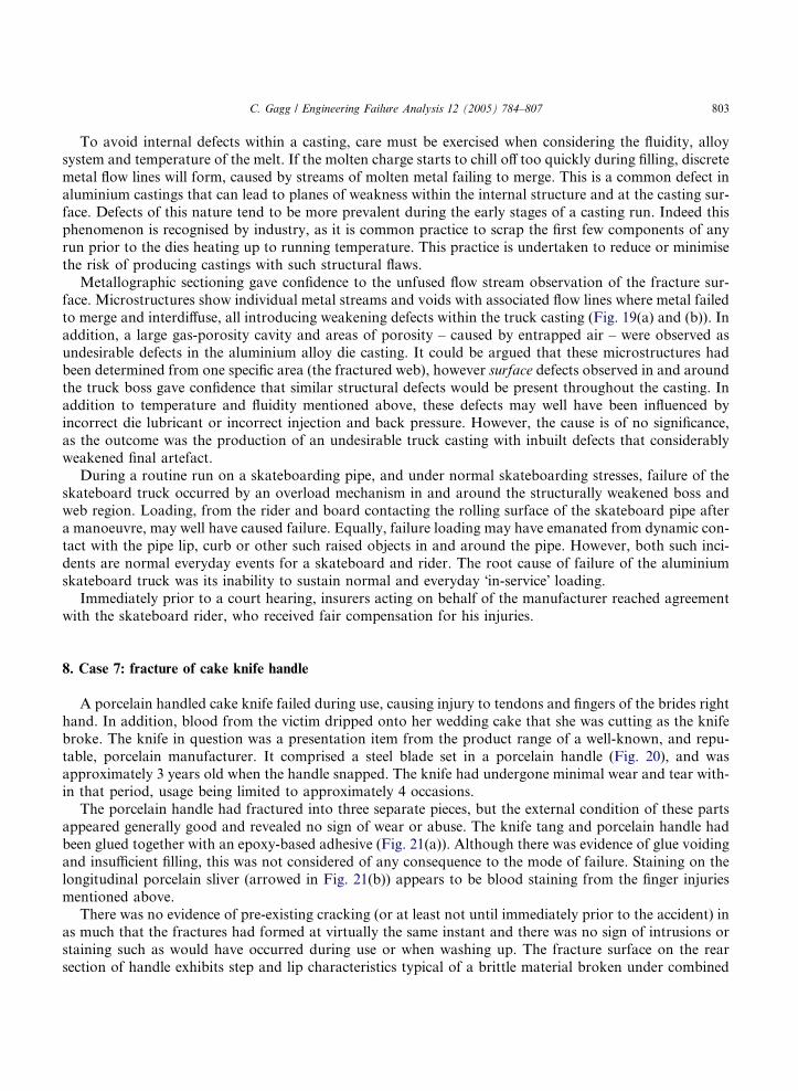
8. Case 7: fracture of cake knife handle
A porcelain handled cake knife failed during use, causing injury to tendons and fingers of the brides right
hand. In addition, blood from the victim dripped onto her wedding cake that she was cutting as the knife
broke. The knife in question was a presentation item from the product range of a well-known, and repu-
table, porcelain manufacturer. It comprised a steel blade set in a porcelain handle (Fig. 20), and was
approximately 3 years old when the handle snapped. The knife had undergone minimal wear and tear with-in that period, usage being limited to approximately 4 occasions.
The porcelain handle had fractured into three separate pieces, but the external condition of these parts
appeared generally good and revealed no sign of wear or abuse. The knife tang and porcelain handle had
been glued together with an epoxy-based adhesive (Fig. 21(a)). Although there was evidence of glue voiding
and insufficient filling, this was not considered of any consequence to the mode of failure. Staining on the
longitudinal porcelain sliver (arrowed in Fig. 21(b)) appears to be blood staining from the finger injuries
mentioned above.
There was no evidence of pre-existing cracking (or at least not until immediately prior to the accident) inas much that the fractures had formed at virtually the same instant and there was no sign of intrusions or
staining such as would have occurred during use or when washing up. The fracture surface on the rear
section of handle exhibits step and lip characteristics typical of a brittle material broken under combined

Fig. 20. General view of the broken knife handle. Note: transverse fracture occurred some two thirds along the length of handle.
Fig. 21. Fracture surface, showing intact thin glue line, end of tang and incomplete glue filling (a). Longitudinal sliver in place, note
blood staining, arrowed (b).
804 C. Gagg / Engineering Failure Analysis 12 (2005) 784–807

C. Gagg / Engineering Failure Analysis 12 (2005) 784–807 805
bending and torsional overload. The handle snapped under heavy pressure applied at the end of the handle,
and was consistent with cutting and twisting action of the blade. There was no evidence of any pre-existing
material fault in the handle that could account for undue weakness.
Although in excess of three years old, the cake knife had experienced little in the way of a ‘‘service life’’.
There was no visible evidence of pre-existing cracks that might indicate a high degree of wear and tear fromexcessive use or from accidental impact (i.e., dropping onto a table or hard floor). The condition of the
knife was such that it appeared to have been stored in its presentation box.
The failure was due to overload, and no evidence was found to suggest a contributory material defect or
flaw. However, criticism can be levelled at the design and manufacture on the grounds of tang length to
handle length and the way this particular tang had been set inside the handle. It will be seen (Fig. 21) that
fracture occurred exactly at the end of the tang, some two thirds the way along the length of the porcelain
handle (Fig. 20). The rear unsupported half of the handle becoming in effect, a cantilever beam operated by
two people (cutting a wedding cake). This action would increase the operating forces (or effort) involved ifthe icing were hard.
When designing an article like a knife, attention has to be paid to the regions where bending moments
are produced, and are greatest. These would be the regions most vulnerable to gross overload failure; in this
instance where the tang of the knife ends within the hollow handle section (the fixed end of a cantilever
beam). Potentially high bending moments at that point could have been easily countered by extending
the metal tang almost to the end of the hole in the handle, an additional 35 mm. Such extension of the tang
would have provided much greater mechanical support for the handle and in addition would move the can-
tilever effect towards the end – where any bending stress applied during cutting would be almost zero. Itwould thus have been practically impossible to break the handle as actually occurred, no matter how great
the hand pressure.
The external condition of the cake knife appeared to be in good condition with little or no sign of �in-service� wear or abuse. Failure was due to a combined bending and torsional overload mechanism that ex-
ceeded the strength of the porcelain, with no evidence found to suggest a contributory material defect or
flaw. Design of the handle can be criticised in that the ratio of tang to handle length allowed a cantilever
effect to occur at the point of maximum bending in the handle section. Design features of this nature are
readily foreseeable from knowledge of basic engineering mechanics and materials principles. The unfortu-nate consequences of this breakage could have been avoided if the metal tang had extended almost the full
length of the handle and if the end of the tang had not been directly in contact with the side of the hole in
the porcelain. More importantly, the use of brittle materials (including brittle polymers) for knife handles
should be avoided if at all possible.
9. Case 8: cycle accident
A car struck a wooden post after knocking a cyclist off of his bicycle. However, the driver of the vehicle
did not stop, he just drove on – a typical �hit and run� accident. A witness saw the car drive off but was
unable to get the vehicle registration number. Nevertheless, the witness was able to provide a detailed
description of make, colour, etc. of the suspect vehicle. A vehicle matching the description was located
sometime later, and a sliver of wood was found inside one of its headlights where the lens glass had broken.
The vehicle owner claimed that he had run into his own wooden fence, hence the damage to his vehicle
and the wood within its headlight. However, comparative observation on a scanning electron microscope
(SEM) revealed a different story. A sample taken from the suspects fence proved the wood to be birch(micrograph (a) in Fig. 22), whereas the sliver recovered from inside his headlight was pine (micrograph
(b) in Fig. 22). Samples from the post that had been struck at the accident scene showed that it was also
pine.

Fig. 22. SEM micrographs of specimens of (a) Birch, taken from a suspect�s wooden fence, and (b) pine that was recovered from inside
a headlight of the suspect car. The pine structure being an exact match with that of the post that was struck during a �hit-and-run� roadtraffic accident.
806 C. Gagg / Engineering Failure Analysis 12 (2005) 784–807
Thus a simple comparison of respective microstructures revealed that the suspect vehicle was the one in-
volved in the hit and run incident. If further proof were required, chemical analysis of the paint work would
have been instigated. This proved unnecessary as the vehicle owner confessed when confronted with the
SEM evidence.1
1 A few days after the accident, the cyclist died from his injuries.

C. Gagg / Engineering Failure Analysis 12 (2005) 784–807 807
References
[1] Road accidents Great Britain:2000. The casualty report, Department for Transport, Local Government and the Regions, the
Stationery office – London; 2001, ISBN: 0-11-552303-0.
[2] Mortality statistics: cause: England and Wales, Office for National Statistics, the Stationery office – London; 2002, Series DH2,
No. 27, ISBN: 1-85774-477-2.
[3] Registrar General for Scotland, Annual Report: 2000, General Register Office for Scotland, Edinburgh; 2001, ISBN: 1-874451-62-
1.
[4] Registrar General for Northern Ireland, Annual Report: 2000, The Stationery Office, London; 2001, ISBN: 0-337-08542-0.
[5] Home accident surveillance system (HASS), 1999 data, DTI, London.
[6] Product design trends, DTI, London; 1989.
[7] Research on the pattern and trends in home accidents, DTI, London, October; 1999.
[8] Successful health and safety management, HSG65, HSE books; 1998, ISBN 0 7176 1276 7.
[9] Smithells metals reference book, 7th ed. Butterworth Heinemann; 1992, ISBN: 0 7506 1020 4.
[10] Deformations in pure bending, Mechanics of engineering materials, Benham, Crawford and Armstrong, Publisher Longman;
1996. p. 133–4.