doe fundamentals handbook - mait4us -...
TRANSCRIPT
DOE-HDBK-1011/1-92JUNE 1992
DOE FUNDAMENTALS HANDBOOKELECTRICAL SCIENCEVolume 1 of 4
U.S. Department of Energy FSC-6910Washington, D.C. 20585
Distribution Statement A. Approved for public release; distribution is unlimited.
This document has been reproduced directly from the best available copy.
Available to DOE and DOE contractors from the Office of Scientific and Technical Information.P. O. Box 62, Oak Ridge, TN 37831; (615) 576-8401.
Available to the public from the National Technical Information Service, U.S. Department ofCommerce, 5285 Port Royal Rd., Springfield, VA 22161.
Order No. DE92019785
ELECTRICAL SCIENCE
Rev. 0 ES
ABSTRACT
The Electrical Science Fundamentals Handbook was developed to assist nuclear facilityoperating contractors provide operators, maintenance personnel, and the technical staff withthe necessary fundamentals training to ensure a basic understanding of electrical theory,terminology, and application. The handbook includes information on alternating current (AC)and direct current (DC) theory, circuits, motors, and generators; AC power and reactivecomponents; batteries; AC and DC voltage regulators; transformers; and electrical testinstruments and measuring devices. This information will provide personnel with a foundationfor understanding the basic operation of various types of DOE nuclear facility electricalequipment.
Key Words: Training Material, Magnetism, DC Theory, DC Circuits, Batteries, DCGenerators, DC Motors, AC Theory, AC Power, AC Generators, Voltage Regulators, ACMotors, Transformers, Test Instruments, Electrical Distribution

ELECTRICAL SCIENCE
Rev. 0 ES
FOREWORD
The Department of Energy (DOE) Fundamentals Handbooks consist of ten academicsubjects, which include Mathematics; Classical Physics; Thermodynamics, Heat Transfer, andFluid Flow; Instrumentation and Control; Electrical Science; Material Science; MechanicalScience; Chemistry; Engineering Symbology, Prints, and Drawings; and Nuclear Physics andReactor Theory. The handbooks are provided as an aid to DOE nuclear facility contractors.
These handbooks were first published as Reactor Operator Fundamentals Manuals in1985 for use by DOE category A reactors. The subject areas, subject matter content, and levelof detail of the Reactor Operator Fundamentals Manuals were determined from several sources.DOE Category A reactor training managers determined which materials should be included, andserved as a primary reference in the initial development phase. Training guidelines from thecommercial nuclear power industry, results of job and task analyses, and independent input fromcontractors and operations-oriented personnel were all considered and included to some degreein developing the text material and learning objectives.
The DOE Fundamentals Handbooks represent the needs of various DOE nuclearfacilities' fundamental training requirements. To increase their applicability to nonreactor nuclearfacilities, the Reactor Operator Fundamentals Manual learning objectives were distributed to theNuclear Facility Training Coordination Program Steering Committee for review and comment.To update their reactor-specific content, DOE Category A reactor training managers alsoreviewed and commented on the content. On the basis of feedback from these sources,information that applied to two or more DOE nuclear facilities was considered generic and wasincluded. The final draft of each of the handbooks was then reviewed by these two groups. Thisapproach has resulted in revised modular handbooks that contain sufficient detail such that eachfacility may adjust the content to fit their specific needs.
Each handbook contains an abstract, a foreword, an overview, learning objectives, andtext material, and is divided into modules so that content and order may be modified byindividual DOE contractors to suit their specific training needs. Each subject area is supportedby a separate examination bank with an answer key.
The DOE Fundamentals Handbooks have been prepared for the Assistant Secretary forNuclear Energy, Office of Nuclear Safety Policy and Standards, by the DOE TrainingCoordination Program. This program is managed by EG&G Idaho, Inc.

ELECTRICAL SCIENCE
Rev. 0 ES
OVERVIEW
The Department of Energy Fundamentals Handbook entitled Electrical Science wasprepared as an information resource for personnel who are responsible for the operation of theDepartment's nuclear facilities. A basic understanding of electricity and electrical systems isnecessary for DOE nuclear facility operators, maintenance personnel, and the technical staff tosafely operate and maintain the facility and facility support systems. The information in thehandbook is presented to provide a foundation for applying engineering concepts to the job.This knowledge will help personnel more fully understand the impact that their actions may haveon the safe and reliable operation of facility components and systems.
The Electrical Science handbook consists of fifteen modules that are contained in fourvolumes. The following is a brief description of the information presented in each module of thehandbook.
Volume 1 of 4
Module 1 - Basic Electrical Theory
This module describes basic electrical concepts and introduces electricalterminology.
Module 2 - Basic DC Theory
This module describes the basic concepts of direct current (DC) electrical circuitsand discusses the associated terminology.
Volume 2 of 4
Module 3 - DC Circuits
This module introduces the rules associated with the reactive components ofinductance and capacitance and how they affect DC circuits.
Module 4 - Batteries
This module introduces batteries and describes the types of cells used, circuitarrangements, and associated hazards.

ELECTRICAL SCIENCE
Rev. 0 ES
Module 5 - DC Generators
This module describes the types of DC generators and their application in termsof voltage production and load characteristics.
Module 6 - DC Motors
This module describes the types of DC motors and includes discussions of speedcontrol, applications, and load characteristics.
Volume 3 of 4
Module 7 - Basic AC Theory
This module describes the basic concepts of alternating current (AC) electricalcircuits and discusses the associated terminology.
Module 8 - AC Reactive Components
This module describes inductance and capacitance and their effects on ACcircuits.
Module 9 - AC Power
This module presents power calculations for single-phase and three-phase ACcircuits and includes the power triangle concept.
Module 10 - AC Generators
This module describes the operating characteristics of AC generators andincludes terminology, methods of voltage production, and methods of parallelingAC generation sources.
Module 11 - Voltage Regulators
This module describes the basic operation and application of voltage regulators.Volume 4 of 4
Module 12 - AC Motors
This module explains the theory of operation of AC motors and discusses thevarious types of AC motors and their application.

ELECTRICAL SCIENCE
Rev. 0 ES
Module 13 - Transformers
This module introduces transformer theory and includes the types oftransformers, voltage/current relationships, and application.
Module 14 - Test Instruments and Measuring Devices
This module describes electrical measuring and test equipment and includes theparameters measured and the principles of operation of common instruments.
Module 15 - Electrical Distribution Systems
This module describes basic electrical distribution systems and includescharacteristics of system design to ensure personnel and equipment safety.
The information contained in this handbook is by no means all encompassing. An attemptto present the entire subject of electrical science would be impractical. However, the ElectricalScience handbook does present enough information to provide the reader with a fundamentalknowledge level sufficient to understand the advanced theoretical concepts presented in othersubject areas, and to better understand basic system and equipment operations.

Department of EnergyFundamentals Handbook
ELECTRICAL SCIENCEModule 1
Basic Electrical Theory

Basic Electrical Theory TABLE OF CONTENTS
TABLE OF CONTENTS
LIST OF FIGURES . . . . . . . . . . . . . . . . . . . . . . . . . . . . . . . . . . . . . . . . . . . . . . . . . . iv
LIST OF TABLES . . . . . . . . . . . . . . . . . . . . . . . . . . . . . . . . . . . . . . . . . . . . . . . . . . . vi
REFERENCES . . . . . . . . . . . . . . . . . . . . . . . . . . . . . . . . . . . . . . . . . . . . . . . . . . . . vii
OBJECTIVES . . . . . . . . . . . . . . . . . . . . . . . . . . . . . . . . . . . . . . . . . . . . . . . . . . . . .viii
ATOM AND ITS FORCES . . . . . . . . . . . . . . . . . . . . . . . . . . . . . . . . . . . . . . . . . . . . 1
The Atom . . . . . . . . . . . . . . . . . . . . . . . . . . . . . . . . . . . . . . . . . . . . . . . . . . . . 1Electrostatic Force. . . . . . . . . . . . . . . . . . . . . . . . . . . . . . . . . . . . . . . . . . . . . . 2The First Law of Electrostatics. . . . . . . . . . . . . . . . . . . . . . . . . . . . . . . . . . . . . 3Electrostatic Field . . . . . . . . . . . . . . . . . . . . . . . . . . . . . . . . . . . . . . . . . . . . . . 3Potential Difference. . . . . . . . . . . . . . . . . . . . . . . . . . . . . . . . . . . . . . . . . . . . . 5Free Electrons. . . . . . . . . . . . . . . . . . . . . . . . . . . . . . . . . . . . . . . . . . . . . . . . . 6Summary . . . . . . . . . . . . . . . . . . . . . . . . . . . . . . . . . . . . . . . . . . . . . . . . . . . . 8
ELECTRICAL TERMINOLOGY . . . . . . . . . . . . . . . . . . . . . . . . . . . . . . . . . . . . . . . . 9
Conductors. . . . . . . . . . . . . . . . . . . . . . . . . . . . . . . . . . . . . . . . . . . . . . . . . . . 9Insulators . . . . . . . . . . . . . . . . . . . . . . . . . . . . . . . . . . . . . . . . . . . . . . . . . . . . 9Resistors. . . . . . . . . . . . . . . . . . . . . . . . . . . . . . . . . . . . . . . . . . . . . . . . . . . . . 9Voltage . . . . . . . . . . . . . . . . . . . . . . . . . . . . . . . . . . . . . . . . . . . . . . . . . . . . 10Current. . . . . . . . . . . . . . . . . . . . . . . . . . . . . . . . . . . . . . . . . . . . . . . . . . . . . 10Real and Ideal Sources. . . . . . . . . . . . . . . . . . . . . . . . . . . . . . . . . . . . . . . . . . 12Summary . . . . . . . . . . . . . . . . . . . . . . . . . . . . . . . . . . . . . . . . . . . . . . . . . . . 12
UNITS OF ELECTRICAL MEASUREMENT. . . . . . . . . . . . . . . . . . . . . . . . . . . . . . . 13
System Internationale (SI) Metric System. . . . . . . . . . . . . . . . . . . . . . . . . . . . . 13Voltage . . . . . . . . . . . . . . . . . . . . . . . . . . . . . . . . . . . . . . . . . . . . . . . . . . . . 13Current. . . . . . . . . . . . . . . . . . . . . . . . . . . . . . . . . . . . . . . . . . . . . . . . . . . . . 14Resistance . . . . . . . . . . . . . . . . . . . . . . . . . . . . . . . . . . . . . . . . . . . . . . . . . . 14Ohm’s Law. . . . . . . . . . . . . . . . . . . . . . . . . . . . . . . . . . . . . . . . . . . . . . . . . . 14Conductance. . . . . . . . . . . . . . . . . . . . . . . . . . . . . . . . . . . . . . . . . . . . . . . . . 16Power . . . . . . . . . . . . . . . . . . . . . . . . . . . . . . . . . . . . . . . . . . . . . . . . . . . . . 16
Rev. 0 Page i ES-01
TABLE OF CONTENTS Basic Electrical Theory
TABLE OF CONTENTS (Cont.)
Inductance . . . . . . . . . . . . . . . . . . . . . . . . . . . . . . . . . . . . . . . . . . . . . . . . . . 17Capacitance . . . . . . . . . . . . . . . . . . . . . . . . . . . . . . . . . . . . . . . . . . . . . . . . . 17Summary . . . . . . . . . . . . . . . . . . . . . . . . . . . . . . . . . . . . . . . . . . . . . . . . . . . 18
METHODS OF PRODUCING VOLTAGE (ELECTRICITY). . . . . . . . . . . . . . . . . . . . 19
Electrochemistry . . . . . . . . . . . . . . . . . . . . . . . . . . . . . . . . . . . . . . . . . . . . . . 19Static Electricity . . . . . . . . . . . . . . . . . . . . . . . . . . . . . . . . . . . . . . . . . . . . . . 20Magnetic Induction . . . . . . . . . . . . . . . . . . . . . . . . . . . . . . . . . . . . . . . . . . . . 21Piezoelectric Effect . . . . . . . . . . . . . . . . . . . . . . . . . . . . . . . . . . . . . . . . . . . . 21Thermoelectricity. . . . . . . . . . . . . . . . . . . . . . . . . . . . . . . . . . . . . . . . . . . . . . 22Photoelectric Effect. . . . . . . . . . . . . . . . . . . . . . . . . . . . . . . . . . . . . . . . . . . . 23Thermionic Emission. . . . . . . . . . . . . . . . . . . . . . . . . . . . . . . . . . . . . . . . . . . 24Summary . . . . . . . . . . . . . . . . . . . . . . . . . . . . . . . . . . . . . . . . . . . . . . . . . . . 26
MAGNETISM . . . . . . . . . . . . . . . . . . . . . . . . . . . . . . . . . . . . . . . . . . . . . . . . . . . . . 27
Magnetism . . . . . . . . . . . . . . . . . . . . . . . . . . . . . . . . . . . . . . . . . . . . . . . . . . 27Magnetic Flux. . . . . . . . . . . . . . . . . . . . . . . . . . . . . . . . . . . . . . . . . . . . . . . . 29Magnetic Flux Density. . . . . . . . . . . . . . . . . . . . . . . . . . . . . . . . . . . . . . . . . . 29Magnetic Materials . . . . . . . . . . . . . . . . . . . . . . . . . . . . . . . . . . . . . . . . . . . . 30Electromagnetism. . . . . . . . . . . . . . . . . . . . . . . . . . . . . . . . . . . . . . . . . . . . . 31Polarity of a Single Conductor. . . . . . . . . . . . . . . . . . . . . . . . . . . . . . . . . . . . 31Magnetic Field and Polarity of a Coil. . . . . . . . . . . . . . . . . . . . . . . . . . . . . . . 32Magnetomotive Force. . . . . . . . . . . . . . . . . . . . . . . . . . . . . . . . . . . . . . . . . . . 33Field Intensity . . . . . . . . . . . . . . . . . . . . . . . . . . . . . . . . . . . . . . . . . . . . . . . . 34Reluctance . . . . . . . . . . . . . . . . . . . . . . . . . . . . . . . . . . . . . . . . . . . . . . . . . . 35Summary . . . . . . . . . . . . . . . . . . . . . . . . . . . . . . . . . . . . . . . . . . . . . . . . . . . 36
MAGNETIC CIRCUITS . . . . . . . . . . . . . . . . . . . . . . . . . . . . . . . . . . . . . . . . . . . . . . 37
Magnetic Circuits . . . . . . . . . . . . . . . . . . . . . . . . . . . . . . . . . . . . . . . . . . . . . 37BH Magnetization Curve. . . . . . . . . . . . . . . . . . . . . . . . . . . . . . . . . . . . . . . . 39Hysteresis. . . . . . . . . . . . . . . . . . . . . . . . . . . . . . . . . . . . . . . . . . . . . . . . . . . 40Magnetic Induction . . . . . . . . . . . . . . . . . . . . . . . . . . . . . . . . . . . . . . . . . . . . 41Faraday’s Law of Induced Voltage. . . . . . . . . . . . . . . . . . . . . . . . . . . . . . . . . 42Lenz’s Law. . . . . . . . . . . . . . . . . . . . . . . . . . . . . . . . . . . . . . . . . . . . . . . . . . 43Summary . . . . . . . . . . . . . . . . . . . . . . . . . . . . . . . . . . . . . . . . . . . . . . . . . . . 44
ES-01 Page ii Rev. 0
Basic Electrical Theory TABLE OF CONTENTS
TABLE OF CONTENTS (Cont.)
ELECTRICAL SYMBOLS . . . . . . . . . . . . . . . . . . . . . . . . . . . . . . . . . . . . . . . . . . . . 45
Symbols . . . . . . . . . . . . . . . . . . . . . . . . . . . . . . . . . . . . . . . . . . . . . . . . . . . . 45Summary . . . . . . . . . . . . . . . . . . . . . . . . . . . . . . . . . . . . . . . . . . . . . . . . . . . 47
APPENDIX A Metric System and Powers of Ten. . . . . . . . . . . . . . . . . . . . . . . . . . . A-1
Rev. 0 Page iii ES-01
LIST OF FIGURES Basic Electrical Theory
LIST OF FIGURES
Figure 1 The Atom. . . . . . . . . . . . . . . . . . . . . . . . . . . . . . . . . . . . . . . . . . . . . . . 1
Figure 2 The Carbon Atom. . . . . . . . . . . . . . . . . . . . . . . . . . . . . . . . . . . . . . . . . 2
Figure 3 Electrostatic Force. . . . . . . . . . . . . . . . . . . . . . . . . . . . . . . . . . . . . . . . . 2
Figure 4 Electrostatic Field. . . . . . . . . . . . . . . . . . . . . . . . . . . . . . . . . . . . . . . . . 3
Figure 5 Electrostatic Field Between Two Charges of Opposite Polarity. . . . . . . . . . 4
Figure 6 Electrostatic Field Between Two Charges of Like Polarity. . . . . . . . . . . . . 4
Figure 7 Potential Difference Between Two Charged Objects. . . . . . . . . . . . . . . . . 5
Figure 8 Energy Shells and Electron Quota. . . . . . . . . . . . . . . . . . . . . . . . . . . . . . 6
Figure 9 Electron Flow Through a Copper Wire with a Potential Difference. . . . . . 11
Figure 10 Potential Difference Across a Conductor Causes a Current to Flow. . . . . . 11
Figure 11 Voltaic Chemical Cell. . . . . . . . . . . . . . . . . . . . . . . . . . . . . . . . . . . . . 20
Figure 12 Static Electricity. . . . . . . . . . . . . . . . . . . . . . . . . . . . . . . . . . . . . . . . . 20
Figure 13 Generator - Electromagnetic Induction. . . . . . . . . . . . . . . . . . . . . . . . . . 21
Figure 14 Pressure Applied to Certain Crystals Produce an Electric Charge. . . . . . . 22
Figure 15 Heat Energy Causes Copper to Give up Electrons to Zinc. . . . . . . . . . . . 23
Figure 16 Producing Electricity from Light Using a Photovoltaic Cell. . . . . . . . . . . 24
Figure 17 Vacuum Tube Diode. . . . . . . . . . . . . . . . . . . . . . . . . . . . . . . . . . . . . . 25
Figure 18 Electron Spinning Around Nucleus Produces Magnetic Field. . . . . . . . . . 27
Figure 19 Magnetic Domains. . . . . . . . . . . . . . . . . . . . . . . . . . . . . . . . . . . . . . . 28
Figure 20 The Law of Magnetic Attraction and Repulsion. . . . . . . . . . . . . . . . . . . 28
ES-01 Page iv Rev. 0
Basic Electrical Theory LIST OF FIGURES
LIST OF FIGURES (Cont.)
Figure 21 The Magnetic Field Produced by Current in a Conductor. . . . . . . . . . . . . 31
Figure 22 Left-hand Rule for Current Carrying Conductors. . . . . . . . . . . . . . . . . . . 31
Figure 23 Left-hand Rule for Coils. . . . . . . . . . . . . . . . . . . . . . . . . . . . . . . . . . . 32
Figure 24 Left-hand Rule to Find North Pole of an Electromagnet. . . . . . . . . . . . . . 33
Figure 25 Different Physical Forms of Electromagnets. . . . . . . . . . . . . . . . . . . . . . 35
Figure 26 Magnetic Current with Closed Iron Path. . . . . . . . . . . . . . . . . . . . . . . . 38
Figure 27 Typical BH Curve for Two Types of Soft Iron. . . . . . . . . . . . . . . . . . . . 39
Figure 28 Hysteresis Loop for Magnetic Materials. . . . . . . . . . . . . . . . . . . . . . . . . 41
Figure 29 Induced EMF. . . . . . . . . . . . . . . . . . . . . . . . . . . . . . . . . . . . . . . . . . . 42
Figure 30 Electrical Symbols. . . . . . . . . . . . . . . . . . . . . . . . . . . . . . . . . . . . . . . . 46
Rev. 0 Page v ES-01
LIST OF TABLES Basic Electrical Theory
LIST OF TABLES
Table A-1 Base Units of the International Metric System. . . . . . . . . . . . . . . . . . . . A-1
Table A-2 Supplementary SI Units. . . . . . . . . . . . . . . . . . . . . . . . . . . . . . . . . . . . A-2
Table A-3 Derived SI Units. . . . . . . . . . . . . . . . . . . . . . . . . . . . . . . . . . . . . . . . . A-3
Table A-4 Metric Prefixes Used in Electricity. . . . . . . . . . . . . . . . . . . . . . . . . . . . A-4
Table A-5 Powers of 10. . . . . . . . . . . . . . . . . . . . . . . . . . . . . . . . . . . . . . . . . . . A-5
Table A-6 Metric Prefixes Expressed as Powers of 10. . . . . . . . . . . . . . . . . . . . . . A-8
ES-01 Page vi Rev. 0
Basic Electrical Theory REFERENCES
REFERENCES
Gussow, Milton, Schaum’s Outline Series, Basic Electricity, McGraw-Hill.
Academic Program for Nuclear Power Plant Personnel, Volume IV, Columbia, MD:General Physics Corporation, Library of Congress Card #A 326517, 1982.
Sienko and Plane, Chemical Principles and Properties, 2nd Edition, McGraw-Hill.
Academic Program for Nuclear Power Plant Personnel, Volume II, Columbia, MD:General Physics Corporation, Library of Congress Card #A 326517, 1982.
Nasar and Unnewehr, Electromechanics and Electric Machines, John Wiley and Sons.
Van Valkenburgh, Nooger, and Neville, Basic Electricity, Vol. 5, Hayden Book Company.
Exide Industrial Marketing Division, The Storage Battery, Lead-Acid Type, The ElectricStorage Battery Company.
Lister, Eugene C., Electric Circuits and Machines, 5th Edition, McGraw-Hill.
Croft, Carr, Watt, and Summers, American Electricians Handbook, 10th Edition, McGraw-Hill.
Mason, C. Russel, The Art and Science of Protective Relaying, John Wiley and Sons.
Mileaf, Harry, Electricity One - Seven, Revised 2nd Edition, Hayden Book Company.
Buban and Schmitt, Understanding Electricity and Electronics, 3rd Edition, McGraw-Hill.
Kidwell, Walter, Electrical Instruments and Measurements, McGraw-Hill.
Rev. 0 Page vii ES-01
OBJECTIVES Basic Electrical Theory
TERMINAL OBJECTIVE
1.0 Given a simple electrical circuit,APPLY basic electrical theory fundamental principlesto describe circuit operation.
ENABLING OBJECTIVES
1.1 DESCRIBE the following terms:a. Electrostatic forceb. Electrostatic fieldc. Potential differenced. Electromotive force (EMF)e. Ion charge
1.2 DEFINE the following terms:a. Conductorb. Insulatorc. Resistord. Electron current flowe. Conventional current flowf. Direct current (DC)g. Alternating current (AC)h. Ideal sourcei. Real source
1.3 DESCRIBE the following electrical parameters, including the unit of measurement andthe relationship to other parameters.a. Voltageb. Currentc. Resistanced. Conductancee. Powerf. Inductanceg. Capacitance
1.4 Given any two of the three component values of Ohm’s Law,DETERMINE theunknown component value.
ES-01 Page viii Rev. 0
Basic Electrical Theory OBJECTIVES
ENABLING OBJECTIVES (Cont.)
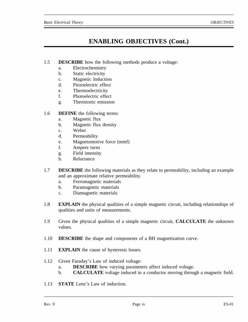
1.5 DESCRIBE how the following methods produce a voltage:a. Electrochemistryb. Static electricityc. Magnetic Inductiond. Piezoelectric effecte. Thermoelectricityf. Photoelectric effectg. Thermionic emission
1.6 DEFINE the following terms:a. Magnetic fluxb. Magnetic flux densityc. Weberd. Permeabilitye. Magnetomotive force (mmf)f. Ampere turnsg. Field intensityh. Reluctance
1.7 DESCRIBE the following materials as they relate to permeability, including an exampleand an approximate relative permeability.a. Ferromagnetic materialsb. Paramagnetic materialsc. Diamagnetic materials
1.8 EXPLAIN the physical qualities of a simple magnetic circuit, including relationships ofqualities and units of measurements.
1.9 Given the physical qualities of a simple magnetic circuit,CALCULATE the unknownvalues.
1.10 DESCRIBE the shape and components of a BH magnetization curve.
1.11 EXPLAIN the cause of hysteresis losses.
1.12 Given Faraday’s Law of induced voltage:a. DESCRIBE how varying parameters affect induced voltage.b. CALCULATE voltage induced in a conductor moving through a magnetic field.
1.13 STATE Lenz’s Law of induction.
Rev. 0 Page ix ES-01
OBJECTIVES Basic Electrical Theory
ENABLING OBJECTIVES (Cont.)
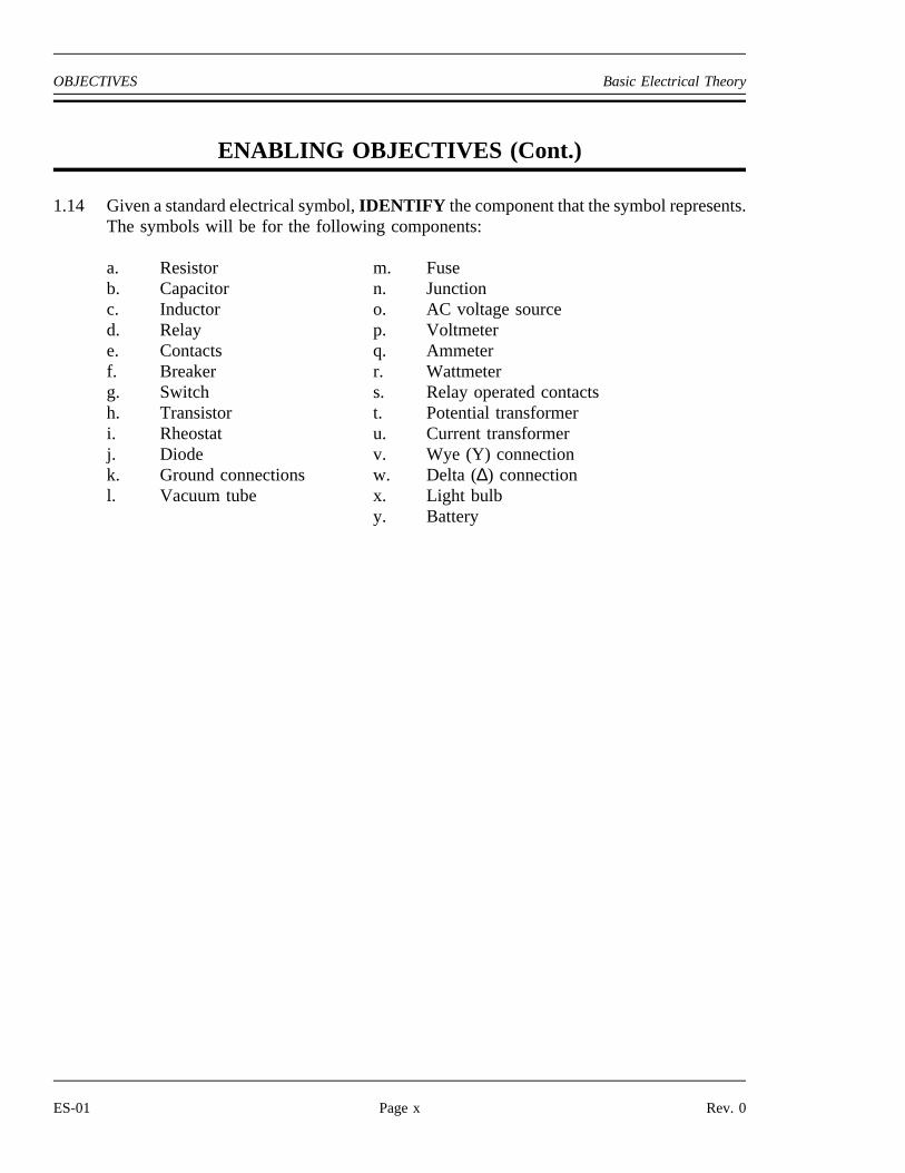
1.14 Given a standard electrical symbol,IDENTIFY the component that the symbol represents.The symbols will be for the following components:
a. Resistor m. Fuseb. Capacitor n. Junctionc. Inductor o. AC voltage sourced. Relay p. Voltmetere. Contacts q. Ammeterf. Breaker r. Wattmeterg. Switch s. Relay operated contactsh. Transistor t. Potential transformeri. Rheostat u. Current transformerj. Diode v. Wye (Y) connectionk. Ground connections w. Delta (∆) connectionl. Vacuum tube x. Light bulb
y. Battery
ES-01 Page x Rev. 0
Basic Electrical Theory ATOM AND ITS FORCES
ATOM AND ITS FORCES
What is electricity? Electricity is defined as "the flow of electrons through simplematerials and devices" or "that force which moves electrons." Scientists thinkelectricity is produced by very tiny particles called electrons and protons. Theseparticles are too small to be seen, but exist as subatomic particles in the atom.To understand how they exist, you must first understand the structure of the atom.
EO 1.1 DESCRIBE the following terms:a. Electrostatic forceb. Electrostatic fieldc. Potential differenced. Electromotive force (EMF)e. Ion charge
The Atom
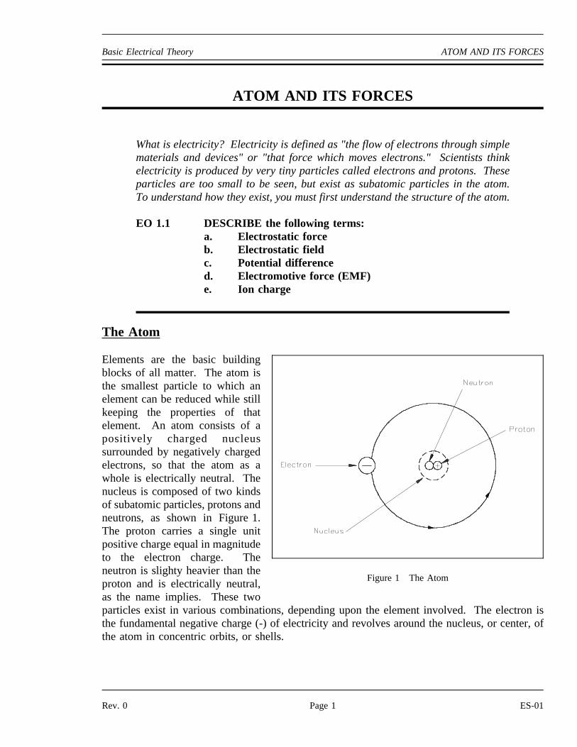
Elements are the basic building
Figure 1 The Atom
blocks of all matter. The atom isthe smallest particle to which anelement can be reduced while stillkeeping the properties of thatelement. An atom consists of apositively charged nucleussurrounded by negatively chargedelectrons, so that the atom as awhole is electrically neutral. Thenucleus is composed of two kindsof subatomic particles, protons andneutrons, as shown in Figure 1.The proton carries a single unitpositive charge equal in magnitudeto the electron charge. Theneutron is slighty heavier than theproton and is electrically neutral,as the name implies. These twoparticles exist in various combinations, depending upon the element involved. The electron isthe fundamental negative charge (-) of electricity and revolves around the nucleus, or center, ofthe atom in concentric orbits, or shells.
Rev. 0 Page 1 ES-01
ATOM AND ITS FORCES Basic Electrical Theory
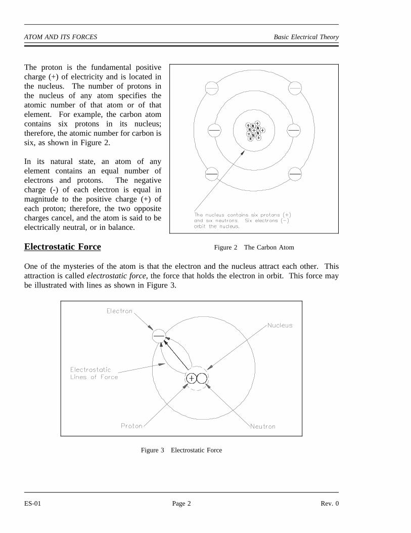
The proton is the fundamental positive
Figure 2 The Carbon Atom
charge (+) of electricity and is located inthe nucleus. The number of protons inthe nucleus of any atom specifies theatomic number of that atom or of thatelement. For example, the carbon atomcontains six protons in its nucleus;therefore, the atomic number for carbon issix, as shown in Figure 2.
In its natural state, an atom of anyelement contains an equal number ofelectrons and protons. The negativecharge (-) of each electron is equal inmagnitude to the positive charge (+) ofeach proton; therefore, the two oppositecharges cancel, and the atom is said to beelectrically neutral, or in balance.
Electrostatic Force
One of the mysteries of the atom is that the electron and the nucleus attract each other. Thisattraction is calledelectrostatic force, the force that holds the electron in orbit. This force maybe illustrated with lines as shown in Figure 3.
Figure 3 Electrostatic Force
ES-01 Page 2 Rev. 0
Basic Electrical Theory ATOM AND ITS FORCES
Without this electrostatic force, the electron, which is traveling at high speed, could not stay inits orbit. Bodies that attract each other in this way are called charged bodies. As mentionedpreviously, the electron has a negative charge, and the nucleus (due to the proton) has a positivecharge.
The First Law of Electrostatics
The negative charge of the electron is equal, but opposite to, the positive charge of the proton.These charges are referred to as electrostatic charges. In nature, unlike charges (like electronsand protons) attract each other, and like charges repel each other. These facts are known as theFirst Law of Electrostaticsand are sometimes referred to as the law of electrical charges. Thislaw should be remembered because it is one of the vital concepts in electricity.
Some atoms can lose electrons and others can gain electrons; thus, it is possible to transferelectrons from one object to another. When this occurs, the equal distribution of negative andpositive charges no longer exists. One object will contain an excess of electrons and becomenegatively charged, and the other will become deficient in electrons and become positivelycharged. These objects, which can contain billions of atoms, will then follow the same law ofelectrostatics as the electron and proton example shown above. The electrons that can movearound within an object are said to be free electrons and will be discussed in more detail in alater section. The greater the number of these free electrons an object contains, the greater itsnegative electric charge. Thus, the electric charge can be used as a measure of electrons.
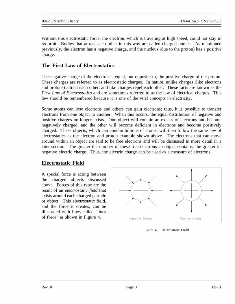
Electrostatic Field
Figure 4 Electrostatic Field
A special force is acting betweenthe charged objects discussedabove. Forces of this type are theresult of anelectrostatic fieldthatexists around each charged particleor object. This electrostatic field,and the force it creates, can beillustrated with lines called "linesof force" as shown in Figure 4.
Rev. 0 Page 3 ES-01
ATOM AND ITS FORCES Basic Electrical Theory
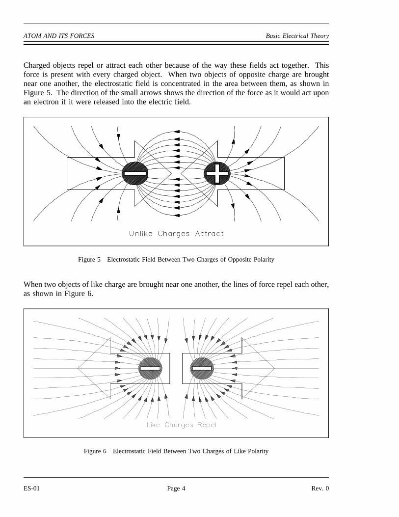
Charged objects repel or attract each other because of the way these fields act together. Thisforce is present with every charged object. When two objects of opposite charge are broughtnear one another, the electrostatic field is concentrated in the area between them, as shown inFigure 5. The direction of the small arrows shows the direction of the force as it would act uponan electron if it were released into the electric field.
When two objects of like charge are brought near one another, the lines of force repel each other,
Figure 5 Electrostatic Field Between Two Charges of Opposite Polarity
as shown in Figure 6.
Figure 6 Electrostatic Field Between Two Charges of Like Polarity
ES-01 Page 4 Rev. 0
Basic Electrical Theory ATOM AND ITS FORCES
The strength of the attraction or of the repulsion force depends upon two factors: (1) the amountof charge on each object, and (2) the distance between the objects. The greater the charge onthe objects, the greater the electrostatic field. The greater the distance between the objects, theweaker the electrostatic field between them, and vice versa. This leads us to the law ofelectrostatic attraction, commonly referred to as Coulomb’s Law of electrostatic charges, whichstates that the force of electrostatic attraction, or repulsion, is directly proportional to the productof the two charges and inversely proportional to the square of the distance between them asshown in Equation 1-1.
(1-1)F Kq1 q2
d2
where
F = force of electrostatic attraction or prepulsion (Newtons)K = constant of proportionality (Coulomb2/N-m2)q1 = charge of first particle (Coulombs)q2 = charge of second particle (Coulombs)d = distance between two particles (Meters)
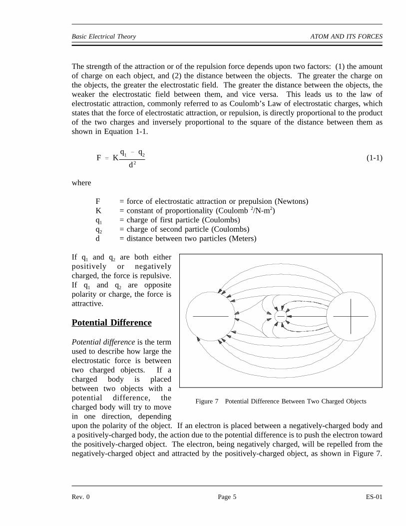
If q1 and q2 are both either
Figure 7 Potential Difference Between Two Charged Objects
positively or negativelycharged, the force is repulsive.If q1 and q2 are oppositepolarity or charge, the force isattractive.
Potential Difference
Potential differenceis the termused to describe how large theelectrostatic force is betweentwo charged objects. If acharged body is placedbetween two objects with apotential difference, thecharged body will try to movein one direction, dependingupon the polarity of the object. If an electron is placed between a negatively-charged body anda positively-charged body, the action due to the potential difference is to push the electron towardthe positively-charged object. The electron, being negatively charged, will be repelled from thenegatively-charged object and attracted by the positively-charged object, as shown in Figure 7.
Rev. 0 Page 5 ES-01
ATOM AND ITS FORCES Basic Electrical Theory
Due to the force of its electrostatic field, these electrical charges have the ability to do work bymoving another charged particle by attraction and/or repulsion. This ability to do work is called"potential"; therefore, if one charge is different from another, there is a potential differencebetween them. The sum of the potential differences of all charged particles in the electrostaticfield is referred to aselectromotive force(EMF).
The basic unit of measure of potential difference is the "volt." The symbol for potentialdifference is "V," indicating the ability to do the work of forcing electrons to move. Becausethe volt unit is used, potential difference is also called "voltage." The unit volt will be coveredin greater detail in the next chapter.
Free Electrons
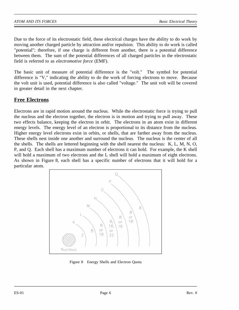
Electrons are in rapid motion around the nucleus. While the electrostatic force is trying to pullthe nucleus and the electron together, the electron is in motion and trying to pull away. Thesetwo effects balance, keeping the electron in orbit. The electrons in an atom exist in differentenergy levels. The energy level of an electron is proportional to its distance from the nucleus.Higher energy level electrons exist in orbits, or shells, that are farther away from the nucleus.These shells nest inside one another and surround the nucleus. The nucleus is the center of allthe shells. The shells are lettered beginning with the shell nearest the nucleus: K, L, M, N, O,P, and Q. Each shell has a maximum number of electrons it can hold. For example, the K shellwill hold a maximum of two electrons and the L shell will hold a maximum of eight electrons.As shown in Figure 8, each shell has a specific number of electrons that it will hold for aparticular atom.
Figure 8 Energy Shells and Electron Quota
ES-01 Page 6 Rev. 0
Basic Electrical Theory ATOM AND ITS FORCES
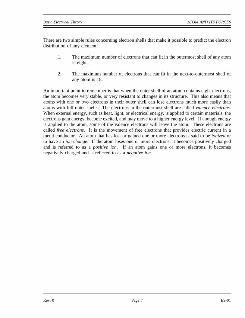
There are two simple rules concerning electron shells that make it possible to predict the electrondistribution of any element:
1. The maximum number of electrons that can fit in the outermost shell of any atomis eight.
2. The maximum number of electrons that can fit in the next-to-outermost shell ofany atom is 18.
An important point to remember is that when the outer shell of an atom contains eight electrons,the atom becomes very stable, or very resistant to changes in its structure. This also means thatatoms with one or two electrons in their outer shell can lose electrons much more easily thanatoms with full outer shells. The electrons in the outermost shell are calledvalence electrons.When external energy, such as heat, light, or electrical energy, is applied to certain materials, theelectrons gain energy, become excited, and may move to a higher energy level. If enough energyis applied to the atom, some of the valence electrons will leave the atom. These electrons arecalled free electrons. It is the movement of free electrons that provides electric current in ametal conductor. An atom that has lost or gained one or more electrons is said to beionizedorto have anion change. If the atom loses one or more electrons, it becomes positively chargedand is referred to as apositive ion. If an atom gains one or more electrons, it becomesnegatively charged and is referred to as anegative ion.
Rev. 0 Page 7 ES-01
ATOM AND ITS FORCES Basic Electrical Theory
Summary
The important information contained in this chapter is summarized below.
Forces Around Atoms Summary
Electrostatic Force - force that holds an electron in orbit around a nucleus
Electrostatic Field - force acting between charged objects that causesthem to repel or attract
Potential Difference - measures how large the electrostatic force isbetween two charged objects. According to Coulomb’s Law, chargedbodies attract or repel each other with a force that is directly proportionalto the product of their charges and is inversely proportional to the squareof the distance between them.
Electromotive Force (EMF) - sum of the potential differences of allcharged particles in an electrostatic field
Ion Charge - dependent on the loss or gain of free electrons (if an atomgains an electron - negative ion charge; if an atom loses an electron -positive ion charge)
ES-01 Page 8 Rev. 0
Basic Electrical Theory ELECTRICAL TERMINOLOGY
ELECTRICAL TERMINOLOGY
Knowledge of key electrical terminology is necessary to fully understandprinciples in electrical science.
EO 1.2 DEFINE the following terms:a. Conductorb. Insulatorc. Resistord. Electron current flowe. Conventional current flowf. Direct current (DC)g. Alternating current (AC)h. Ideal sourcei. Real source
Conductors
Conductorsare materials with electrons that are loosely bound to their atoms, or materials thatpermit free motion of a large number of electrons. Atoms with only one valence electron, suchas copper, silver, and gold, are examples of good conductors. Most metals are good conductors.
Insulators
Insulators, or nonconductors, are materials with electrons that are tightly bound to their atomsand require large amounts of energy to free them from the influence of the nucleus. The atomsof good insulators have their valence shells filled with eight electrons, which means they aremore than half filled. Any energy applied to such an atom will be distributed among a relativelylarge number of electrons. Examples of insulators are rubber, plastics, glass, and dry wood.
Resistors
Resistorsare made of materials that conduct electricity, but offer opposition to current flow.These types of materials are also calledsemiconductorsbecause they are neither good conductorsnor good insulators. Semiconductors have more than one or two electrons in their valence shells,but less than seven or eight. Examples of semiconductors are carbon, silicon, germanium, tin, andlead. Each has four valence electrons.
Rev. 0 Page 9 ES-01
ELECTRICAL TERMINOLOGY Basic Electrical Theory
Voltage
The basic unit of measure for potential difference is thevolt (symbol V), and, because the voltunit is used, potential difference is calledvoltage. An object’s electrical charge is determinedby the number of electrons that the object has gained or lost. Because such a large number ofelectrons move, a unit called the "coulomb" is used to indicate the charge. One coulomb is equalto 6.28 x 10¹⁸ (billion, billion) electrons. For example, if an object gains one coulomb ofnegative charge, it has gained 6,280,000,000,000,000,000 extra electrons. A volt is defined asa difference of potential causing one coulomb of current to do one joule of work. A volt is alsodefined as that amount of force required to force one ampere of current through one ohm ofresistance. The latter is the definition with which we will be most concerned in this module.
Current
The density of the atoms in copper wire is such that the valence orbits of the individual atomsoverlap, causing the electrons to move easily from one atom to the next. Free electrons can driftfrom one orbit to another in a random direction. When a potential difference is applied, thedirection of their movement is controlled. The strength of the potential difference applied at eachend of the wire determines how many electrons change from a random motion to a moredirectional path through the wire. The movement or flow of these electrons is calledelectroncurrent flowor just current.
To produce current, the electrons must be moved by a potential difference. The symbol forcurrent is (I). The basic measurement for current is the ampere (A). One ampere of current isdefined as the movement of one coulomb of charge past any given point of a conductor duringone second of time.
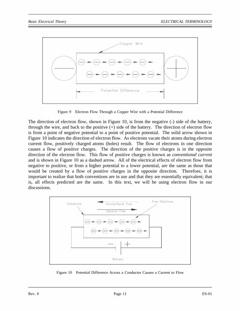
If a copper wire is placed between two charged objects that have a potential difference, all of thenegatively-charged free electrons will feel a force pushing them from the negative charge to thepositive charge. This force opposite to the conventional direction of the electrostatic lines offorce is shown in Figure 9.
ES-01 Page 10 Rev. 0
Basic Electrical Theory ELECTRICAL TERMINOLOGY
Figure 9 Electron Flow Through a Copper Wire with a Potential Difference
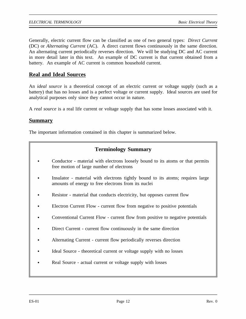
The direction of electron flow, shown in Figure 10, is from the negative (-) side of the battery,through the wire, and back to the positive (+) side of the battery. The direction of electron flowis from a point of negative potential to a point of positive potential. The solid arrow shown inFigure 10 indicates the direction of electron flow. As electrons vacate their atoms during electroncurrent flow, positively charged atoms (holes) result. The flow of electrons in one directioncauses a flow of positive charges. The direction of the positive charges is in the oppositedirection of the electron flow. This flow of positive charges is known asconventional currentand is shown in Figure 10 as a dashed arrow. All of the electrical effects of electron flow fromnegative to positive, or from a higher potential to a lower potential, are the same as those thatwould be created by a flow of positive charges in the opposite direction. Therefore, it isimportant to realize that both conventions are in use and that they are essentially equivalent; thatis, all effects predicted are the same. In this text, we will be using electron flow in ourdiscussions.
Figure 10 Potential Difference Across a Conductor Causes a Current to Flow
Rev. 0 Page 11 ES-01
ELECTRICAL TERMINOLOGY Basic Electrical Theory
Generally, electric current flow can be classified as one of two general types:Direct Current(DC) or Alternating Current(AC). A direct current flows continuously in the same direction.An alternating current periodically reverses direction. We will be studying DC and AC currentin more detail later in this text. An example of DC current is that current obtained from abattery. An example of AC current is common household current.
Real and Ideal Sources
An ideal sourceis a theoretical concept of an electric current or voltage supply (such as abattery) that has no losses and is a perfect voltage or current supply. Ideal sources are used foranalytical purposes only since they cannot occur in nature.
A real sourceis a real life current or voltage supply that has some losses associated with it.
Summary
The important information contained in this chapter is summarized below.
Terminology Summary
Conductor - material with electrons loosely bound to its atoms or that permitsfree motion of large number of electrons
Insulator - material with electrons tightly bound to its atoms; requires largeamounts of energy to free electrons from its nuclei
Resistor - material that conducts electricity, but opposes current flow
Electron Current Flow - current flow from negative to positive potentials
Conventional Current Flow - current flow from positive to negative potentials
Direct Current - current flow continuously in the same direction
Alternating Current - current flow periodically reverses direction
Ideal Source - theoretical current or voltage supply with no losses
Real Source - actual current or voltage supply with losses
ES-01 Page 12 Rev. 0
Basic Electrical Theory UNITS OF ELECTRICAL MEASUREMENT
UNITS OF ELECTRICAL MEASUREMENT
Using Ohm’s Law and the System Internationale (SI) Metric System, electricalmeasuring units can be derived.
EO 1.3 DESCRIBE the following electrical parameters, including theunit of measurement and the relationship to other parameters.a. Voltageb. Currentc. Resistanced. Conductancee. Powerf. Inductanceg. Capacitance
EO 1.4 Given any two of the three component values of Ohm’s Law,DETERMINE the unknown component value.
System Internationale (SI) Metric System
Electrical units of measurement are based on the International (metric) System, also known asthe SI System. Units of electrical measurement include the following:
AmpereVoltOhmSiemensWattHenryFarad
Appendix A provides more information concerning the metric system, metric prefixes, andpowers of 10 that are used in electrical measuring units.
Voltage
Voltage, electromotive force (emf), or potential difference, is described as the pressure or forcethat causes electrons to move in a conductor. In electrical formulas and equations, you will seevoltage symbolized with a capital E, while on laboratory equipment or schematic diagrams, thevoltage is often represented with a capital V.
Rev. 0 Page 13 ES-01
UNITS OF ELECTRICAL MEASUREMENT Basic Electrical Theory
Current
Electron current, or amperage, is described as the movement of free electrons through aconductor. In electrical formulas, current is symbolized with a capital I, while in the laboratoryor on schematic diagrams, it is common to use a capital A to indicate amps or amperage (amps).
Resistance
Now that we have discussed the concepts of voltage and current, we are ready to discuss a thirdkey concept called resistance.Resistanceis defined as the opposition to current flow. Theamount of opposition to current flow produced by a material depends upon the amount ofavailable free electrons it contains and the types of obstacles the electrons encounter as theyattempt to move through the material. Resistance is measured in ohms and is represented by thesymbol (R) in equations. One ohm is defined as that amount of resistance that will limit thecurrent in a conductor to one ampere when the potential difference (voltage) applied to theconductor is one volt. The shorthand notation for ohm is the Greek letter capital omega (Ω). Ifa voltage is applied to a conductor, current flows. The amount of current flow depends upon theresistance of the conductor. The lower the resistance, the higher the current flow for a givenamount of voltage. The higher the resistance, the lower the current flow.
Ohm’s Law
In 1827, George Simon Ohm discovered that there was a definite relationship between voltage,current, and resistance in an electrical circuit. Ohm’s Law defines this relationship and can bestated in three ways.
1. Applied voltage equals circuit current times the circuit resistance. Equation (1-2) is amathematical respresentation of this concept.
E = I x R or E = IR (1-2)
2. Current is equal to the applied voltage divided by the circuit resistance. Equation(1-3) is a mathematical representation of this concept.
(1-3)I ER
ES-01 Page 14 Rev. 0
Basic Electrical Theory UNITS OF ELECTRICAL MEASUREMENT
3. Resistance of a circuit is equal to the applied voltage divided by the circuit current.Equation (1-4) is a mathematical representation of this concept.
(1-4)R (or Ω) EI
where
I = current (A)
E = voltage (V)
R = resistance (Ω)
If any two of the component values are known, the third can be calculated.
Example 1: Given that I = 2 A, E = 12 V, find the circuit resistance.
Solution:
Since applied voltage and circuit current are known, use Ohm’s Law to solve forresistance.
R EI
R 12 V2 A
6 Ω
Example 2: Given E = 260 V and R = 240Ω, what current will flow through a circuit?
Solution:
Since applied voltage and resistance are known, use Ohm’s Law to solve forcurrent.
I ER
I 260 V240 Ω
1.083 A
Rev. 0 Page 15 ES-01
UNITS OF ELECTRICAL MEASUREMENT Basic Electrical Theory
Example 3: Find the applied voltage, when given circuit resistance of 100Ω and circuit currentof 0.5 amps.
Solution:
Since circuit resistance and circuit current are known, use Ohm’s Law to solve forapplied voltage.
E = IR
E = (0.5 A)(100Ω) = 50 V
Conductance
The word "reciprocal" is sometimes used to mean "the opposite of." The opposite, or reciprocal,of resistance is calledconductance. As described above, resistance is the opposition to currentflow. Since resistance and conductance are opposites, conductance can be defined as the abilityto conduct current. For example, if a wire has a high conductance, it will have low resistance,and vice-versa. Conductance is found by taking the reciprocal of the resistance. The unit usedto specify conductance is called "mho," which is ohm spelled backwards. The symbol for "mho"is the Greek letter omega inverted ( ). The symbol for conductance when used in a formula isG. Equation (1-5) is the mathematical representation of conductance obtained by relating thedefinition of conductance (1/R) to Ohm’s Law, Equation (1-4).
(1-5)G 1RESISTANCE
IE
Example: If a resistor (R) has five ohms, what will its conductance (G) be in mhos?
Solution:
G (or ) 1R
15
0.2
Power
Electricity is generally used to do some sort of work, such as turning a motor or generating heat.Specifically,poweris the rate at which work is done, or the rate at which heat is generated. Theunit commonly used to specify electric power is the watt. In equations, you will find powerabbreviated with the capital letter P, and watts, the units of measure for power, are abbreviatedwith the capital letter W. Power is also described as the current (I) in a circuit times thevoltage (E) across the circuit. Equation (1-6) is a mathematical representation of this concept.
P = I x E or P = IE (1-6)
ES-01 Page 16 Rev. 0
Basic Electrical Theory UNITS OF ELECTRICAL MEASUREMENT
Using Ohm’s Law for the value of voltage (E),
E = I x R
and using substitution laws,
P = I x ( I x R)
power can be described as the current (I) in a circuit squared times the resistance (R) of thecircuit. Equation (1-7) is the mathematical representation of this concept.
P = I2R (1-7)
Inductance
Inductanceis defined as the ability of a coil to store energy, induce a voltage in itself, andoppose changes in current flowing through it. The symbol used to indicate inductance inelectrical formulas and equations is a capital L. The units of measurement are called henries.The unit henry is abbreviated by using the capital letter H. One henry is the amount ofinductance (L) that permits one volt to be induced (VL) when the current through the coil changesat a rate of one ampere per second. Equation (1-8) is the mathematical representation of the rateof change in current through a coil per unit time.
(1-8)
∆I∆t
Equation (1-9) is the mathematical representation for the voltage VL induced in a coil withinductance L. The negative sign indicates that voltage induced opposes the change in currentthrough the coil per unit time (∆I/∆t).
(1-9)VL L
∆I∆t
Inductance will be studied in further detail later in this text.
Capacitance
Capacitanceis defined as the ability to store an electric charge and is symbolized by the capitalletter C. Capacitance (C), measured in farads, is equal to the amount of charge (Q) that can bestored in a device or capacitor divided by the voltage (E) applied across the device or capacitorplates when the charge was stored. Equation (1-10) is the mathematical representation forcapacitance.
(1-10)C QE
Rev. 0 Page 17 ES-01
UNITS OF ELECTRICAL MEASUREMENT Basic Electrical Theory
Summary
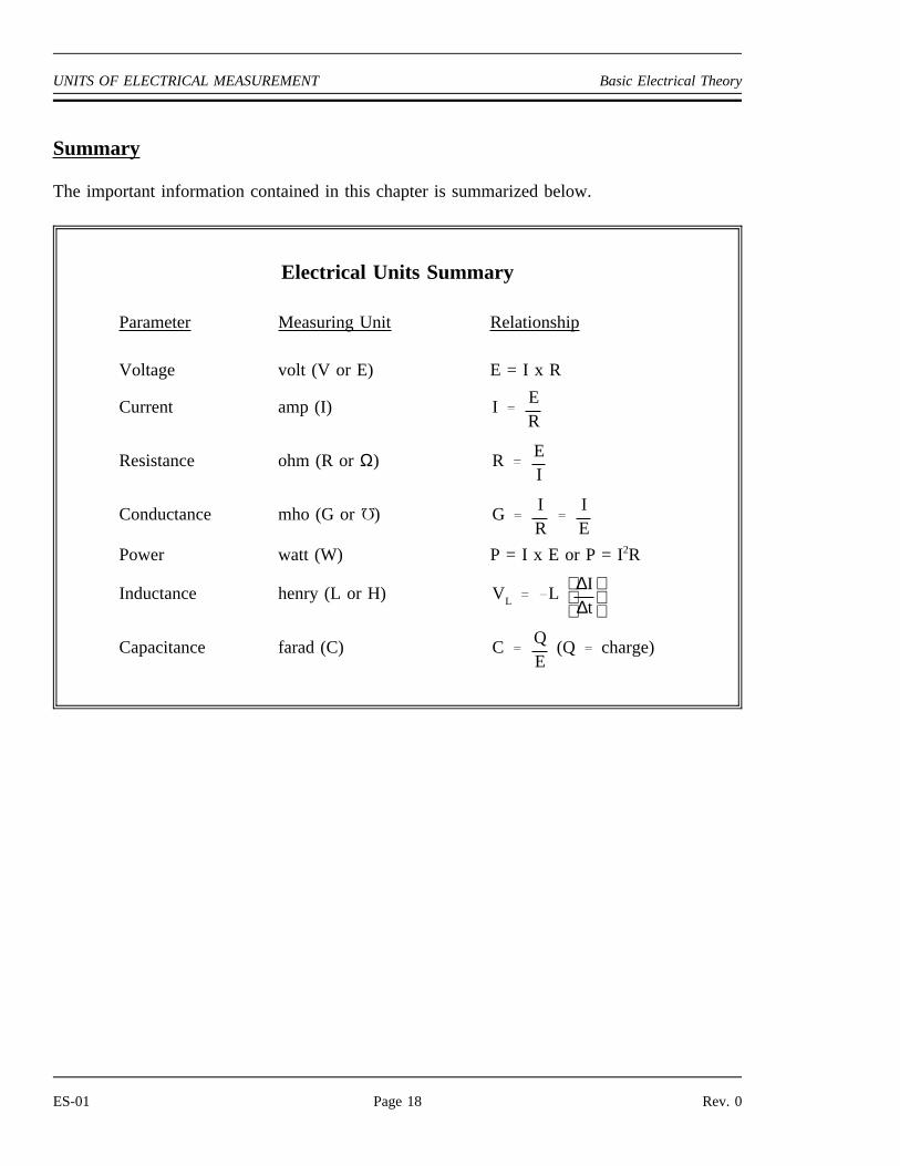
The important information contained in this chapter is summarized below.
Electrical Units Summary
Parameter Measuring Unit Relationship
Voltage volt (V or E) E = I x R
Current amp (I) I ER
Resistance ohm (R orΩ) R EI
Conductance mho (G or ) G IR
IE
Power watt (W) P = I x E or P = I2R
Inductance henry (L or H) VL L
∆I∆t
Capacitance farad (C) C QE
(Q charge)
ES-01 Page 18 Rev. 0
Basic Electrical Theory METHODS OF PRODUCING VOLTAGE (ELECTRICITY)
METHODS OF PRODUCING VOLTAGE (ELECTRICITY)
This section provides information on the following methods of producingelectricity:
ElectrochemistryStatic (friction)Induction (magnetism)Piezoelectric (pressure)Thermal (heat)LightThermionic emission
EO 1.5 DESCRIBE how the following methods produce a voltage:a. Electrochemistryb. Static electricityc. Magnetic inductiond. Piezoelectric effecte. Thermoelectricityf. Photoelectric effectg. Thermionic emission
Electrochemistry
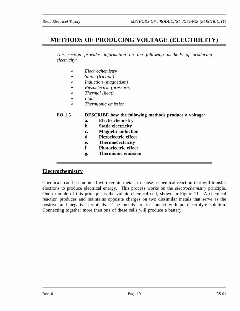
Chemicals can be combined with certain metals to cause a chemical reaction that will transferelectrons to produce electrical energy. This process works on theelectrochemistryprinciple.One example of this principle is the voltaic chemical cell, shown in Figure 11. A chemicalreaction produces and maintains opposite charges on two dissimilar metals that serve as thepositive and negative terminals. The metals are in contact with an electrolyte solution.Connecting together more than one of these cells will produce a battery.
Rev. 0 Page 19 ES-01
METHODS OF PRODUCING VOLTAGE (ELECTRICITY) Basic Electrical Theory
Figure 11 Voltaic Chemical Cell
Example: A battery can maintain a potential difference between its positive and negativeterminals by chemical action. Various types of cells and batteries will be studiedin more detail in Module 4, Batteries.
Static Electricity
Figure 12 Static Electricity
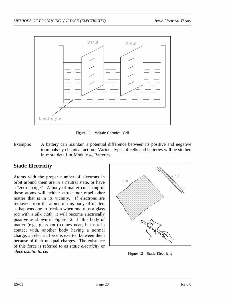
Atoms with the proper number of electrons inorbit around them are in a neutral state, or havea "zero charge." A body of matter consisting ofthese atoms will neither attract nor repel othermatter that is in its vicinity. If electrons areremoved from the atoms in this body of matter,as happens due to friction when one rubs a glassrod with a silk cloth, it will become electricallypositive as shown in Figure 12. If this body ofmatter (e.g., glass rod) comes near, but not incontact with, another body having a normalcharge, an electric force is exerted between thembecause of their unequal charges. The existenceof this force is referred to asstatic electricityorelectrostatic force.
ES-01 Page 20 Rev. 0
Basic Electrical Theory METHODS OF PRODUCING VOLTAGE (ELECTRICITY)
Example: Have you ever walked across a carpet and received a shock when you touched ametal door knob? Your shoe soles built up a charge by rubbing on the carpet, andthis charge was transferred to your body. Your body became positively chargedand, when you touched the zero-charged door knob, electrons were transferred toyour body until both you and the door knob had equal charges.
Magnetic Induction
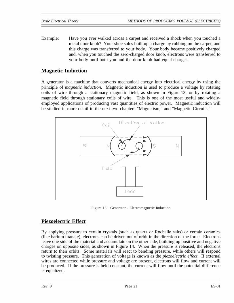
A generator is a machine that converts mechanical energy into electrical energy by using theprinciple of magnetic induction. Magnetic induction is used to produce a voltage by rotatingcoils of wire through a stationary magnetic field, as shown in Figure 13, or by rotating amagnetic field through stationary coils of wire. This is one of the most useful and widely-employed applications of producing vast quantities of electric power. Magnetic induction willbe studied in more detail in the next two chapters "Magnetism," and "Magnetic Circuits."
Figure 13 Generator - Electromagnetic Induction
Piezoelectric Effect
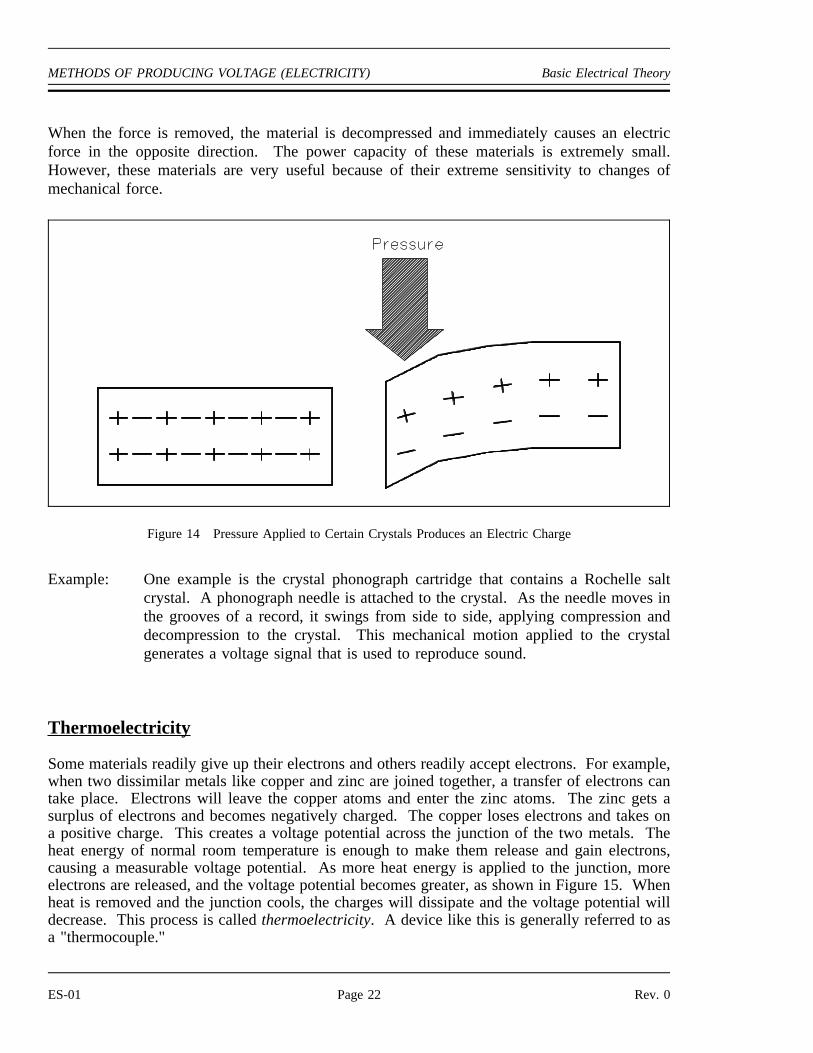
By applying pressure to certain crystals (such as quartz or Rochelle salts) or certain ceramics(like barium titanate), electrons can be driven out of orbit in the direction of the force. Electronsleave one side of the material and accumulate on the other side, building up positive and negativecharges on opposite sides, as shown in Figure 14. When the pressure is released, the electronsreturn to their orbits. Some materials will react to bending pressure, while others will respondto twisting pressure. This generation of voltage is known as thepiezoelectric effect. If externalwires are connected while pressure and voltage are present, electrons will flow and current willbe produced. If the pressure is held constant, the current will flow until the potential differenceis equalized.
Rev. 0 Page 21 ES-01
METHODS OF PRODUCING VOLTAGE (ELECTRICITY) Basic Electrical Theory
When the force is removed, the material is decompressed and immediately causes an electricforce in the opposite direction. The power capacity of these materials is extremely small.However, these materials are very useful because of their extreme sensitivity to changes ofmechanical force.
Example: One example is the crystal phonograph cartridge that contains a Rochelle salt
Figure 14 Pressure Applied to Certain Crystals Produces an Electric Charge
crystal. A phonograph needle is attached to the crystal. As the needle moves inthe grooves of a record, it swings from side to side, applying compression anddecompression to the crystal. This mechanical motion applied to the crystalgenerates a voltage signal that is used to reproduce sound.
Thermoelectricity
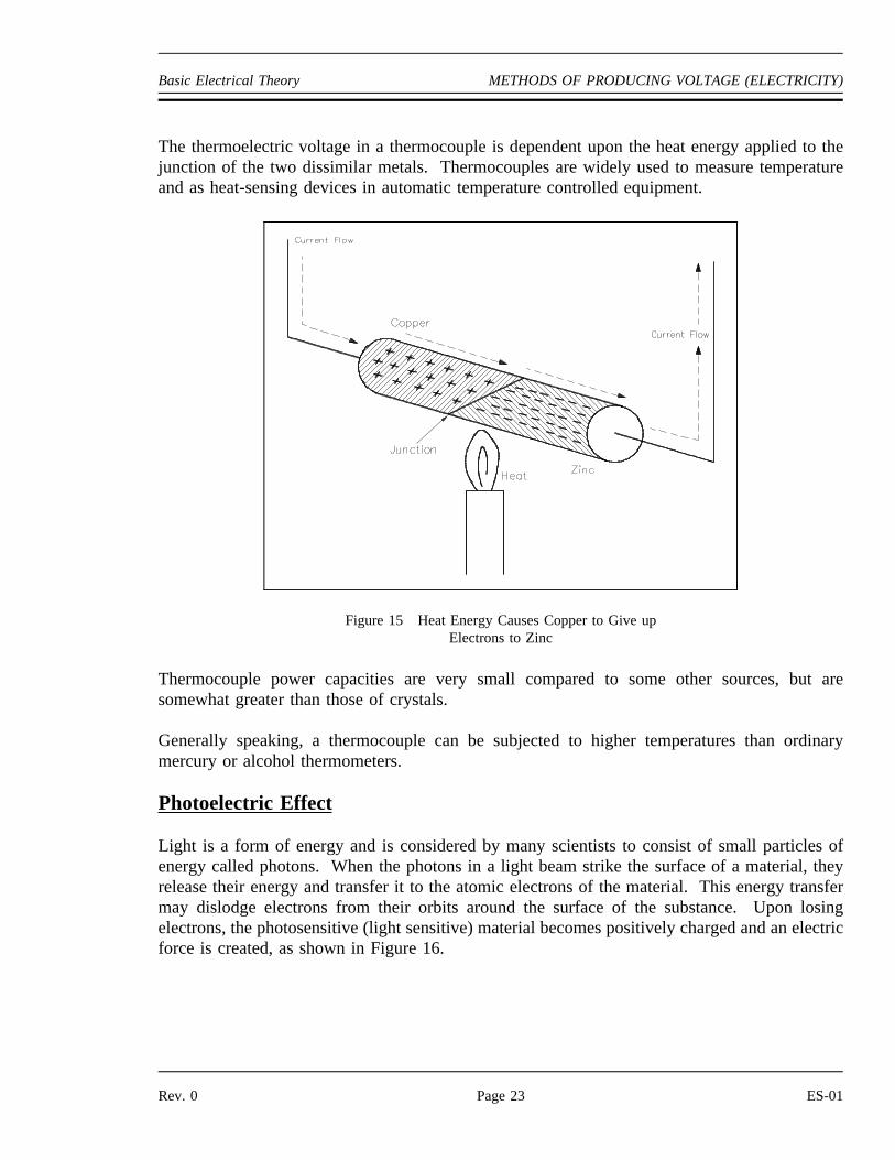
Some materials readily give up their electrons and others readily accept electrons. For example,when two dissimilar metals like copper and zinc are joined together, a transfer of electrons cantake place. Electrons will leave the copper atoms and enter the zinc atoms. The zinc gets asurplus of electrons and becomes negatively charged. The copper loses electrons and takes ona positive charge. This creates a voltage potential across the junction of the two metals. Theheat energy of normal room temperature is enough to make them release and gain electrons,causing a measurable voltage potential. As more heat energy is applied to the junction, moreelectrons are released, and the voltage potential becomes greater, as shown in Figure 15. Whenheat is removed and the junction cools, the charges will dissipate and the voltage potential willdecrease. This process is calledthermoelectricity. A device like this is generally referred to asa "thermocouple."
ES-01 Page 22 Rev. 0
Basic Electrical Theory METHODS OF PRODUCING VOLTAGE (ELECTRICITY)
The thermoelectric voltage in a thermocouple is dependent upon the heat energy applied to thejunction of the two dissimilar metals. Thermocouples are widely used to measure temperatureand as heat-sensing devices in automatic temperature controlled equipment.
Figure 15 Heat Energy Causes Copper to Give upElectrons to Zinc
Thermocouple power capacities are very small compared to some other sources, but aresomewhat greater than those of crystals.
Generally speaking, a thermocouple can be subjected to higher temperatures than ordinarymercury or alcohol thermometers.
Photoelectric Effect
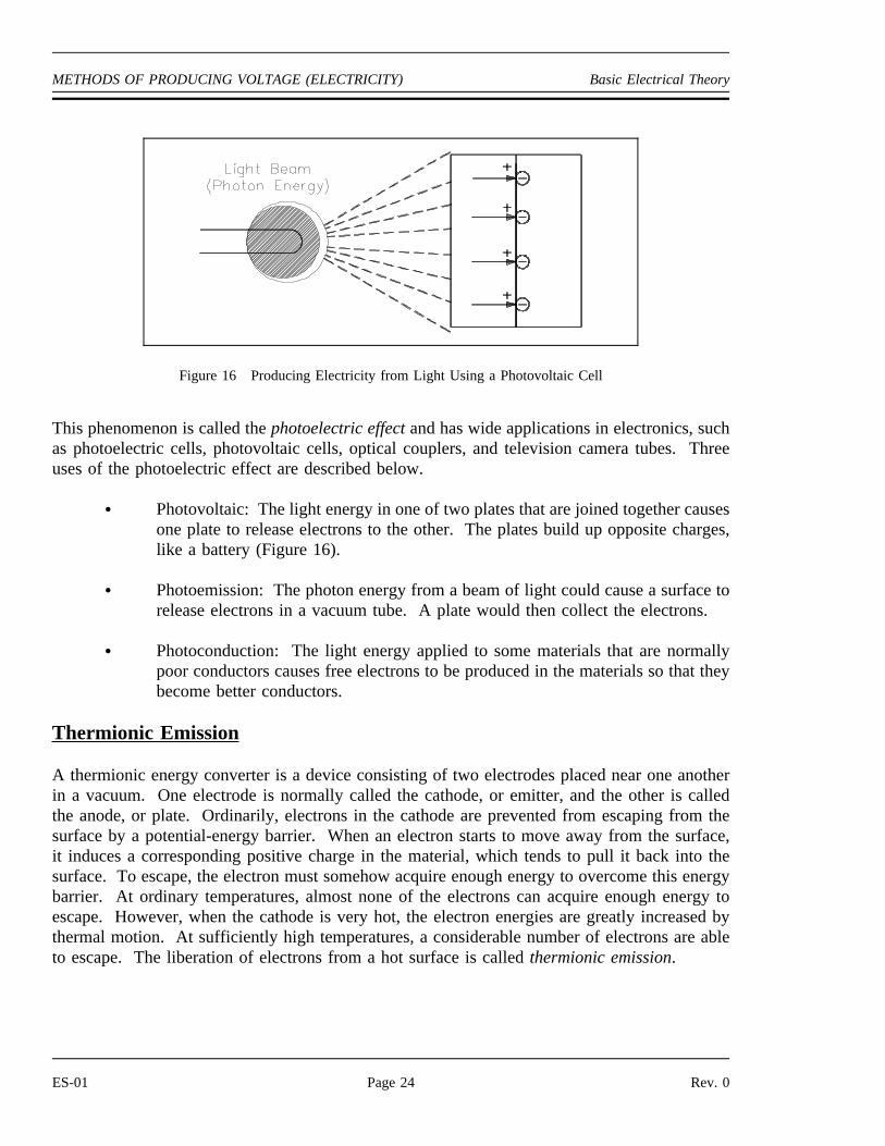
Light is a form of energy and is considered by many scientists to consist of small particles ofenergy called photons. When the photons in a light beam strike the surface of a material, theyrelease their energy and transfer it to the atomic electrons of the material. This energy transfermay dislodge electrons from their orbits around the surface of the substance. Upon losingelectrons, the photosensitive (light sensitive) material becomes positively charged and an electricforce is created, as shown in Figure 16.
Rev. 0 Page 23 ES-01
METHODS OF PRODUCING VOLTAGE (ELECTRICITY) Basic Electrical Theory
Figure 16 Producing Electricity from Light Using a Photovoltaic Cell
This phenomenon is called thephotoelectric effectand has wide applications in electronics, suchas photoelectric cells, photovoltaic cells, optical couplers, and television camera tubes. Threeuses of the photoelectric effect are described below.
Photovoltaic: The light energy in one of two plates that are joined together causesone plate to release electrons to the other. The plates build up opposite charges,like a battery (Figure 16).
Photoemission: The photon energy from a beam of light could cause a surface torelease electrons in a vacuum tube. A plate would then collect the electrons.
Photoconduction: The light energy applied to some materials that are normallypoor conductors causes free electrons to be produced in the materials so that theybecome better conductors.
Thermionic Emission
A thermionic energy converter is a device consisting of two electrodes placed near one anotherin a vacuum. One electrode is normally called the cathode, or emitter, and the other is calledthe anode, or plate. Ordinarily, electrons in the cathode are prevented from escaping from thesurface by a potential-energy barrier. When an electron starts to move away from the surface,it induces a corresponding positive charge in the material, which tends to pull it back into thesurface. To escape, the electron must somehow acquire enough energy to overcome this energybarrier. At ordinary temperatures, almost none of the electrons can acquire enough energy toescape. However, when the cathode is very hot, the electron energies are greatly increased bythermal motion. At sufficiently high temperatures, a considerable number of electrons are ableto escape. The liberation of electrons from a hot surface is calledthermionic emission.
ES-01 Page 24 Rev. 0
Basic Electrical Theory METHODS OF PRODUCING VOLTAGE (ELECTRICITY)
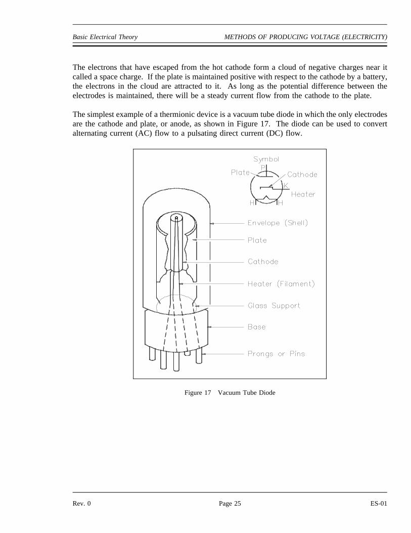
The electrons that have escaped from the hot cathode form a cloud of negative charges near itcalled a space charge. If the plate is maintained positive with respect to the cathode by a battery,the electrons in the cloud are attracted to it. As long as the potential difference between theelectrodes is maintained, there will be a steady current flow from the cathode to the plate.
The simplest example of a thermionic device is a vacuum tube diode in which the only electrodesare the cathode and plate, or anode, as shown in Figure 17. The diode can be used to convertalternating current (AC) flow to a pulsating direct current (DC) flow.
Figure 17 Vacuum Tube Diode
Rev. 0 Page 25 ES-01
METHODS OF PRODUCING VOLTAGE (ELECTRICITY) Basic Electrical Theory
Summary
The important information contained in this chapter is summarized below.
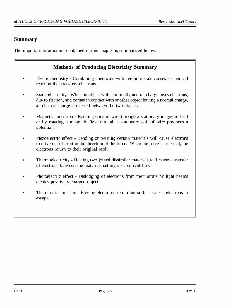
Methods of Producing Electricity Summary
Electrochemistry - Combining chemicals with certain metals causes a chemicalreaction that transfers electrons.
Static electricity - When an object with a normally neutral charge loses electrons,due to friction, and comes in contact with another object having a normal charge,an electric charge is exerted between the two objects.
Magnetic induction - Rotating coils of wire through a stationary magnetic fieldor by rotating a magnetic field through a stationary coil of wire produces apotential.
Piezoelectric effect - Bending or twisting certain materials will cause electronsto drive out of orbit in the direction of the force. When the force is released, theelectrons return to their original orbit.
Thermoelectricity - Heating two joined dissimilar materials will cause a transferof electrons between the materials setting up a current flow.
Photoelectric effect - Dislodging of electrons from their orbits by light beamscreates positively-charged objects.
Thermionic emission - Freeing electrons from a hot surface causes electrons toescape.
ES-01 Page 26 Rev. 0
Basic Electrical Theory MAGNETISM
MAGNETISM
Certain metals and metallic oxides have the ability to attract other metals. Thisproperty is called magnetism, and the materials which have this property arecalled magnets. Some magnets are found naturally while others must bemanufactured.
EO 1.6 DEFINE the following terms:a. Magnetic fluxb. Magnetic flux densityc. Weberd. Permeabilitye. Magnetomotive force (mmf)f. Ampere turnsg. Field intensityh. Reluctance
EO 1.7 DESCRIBE the following materials as they relate topermeability, including an example and an approximate relativepermeablity.a. Ferromagnetic materialsb. Paramagnetic materialsc. Diamagnetic materials
Magnetism
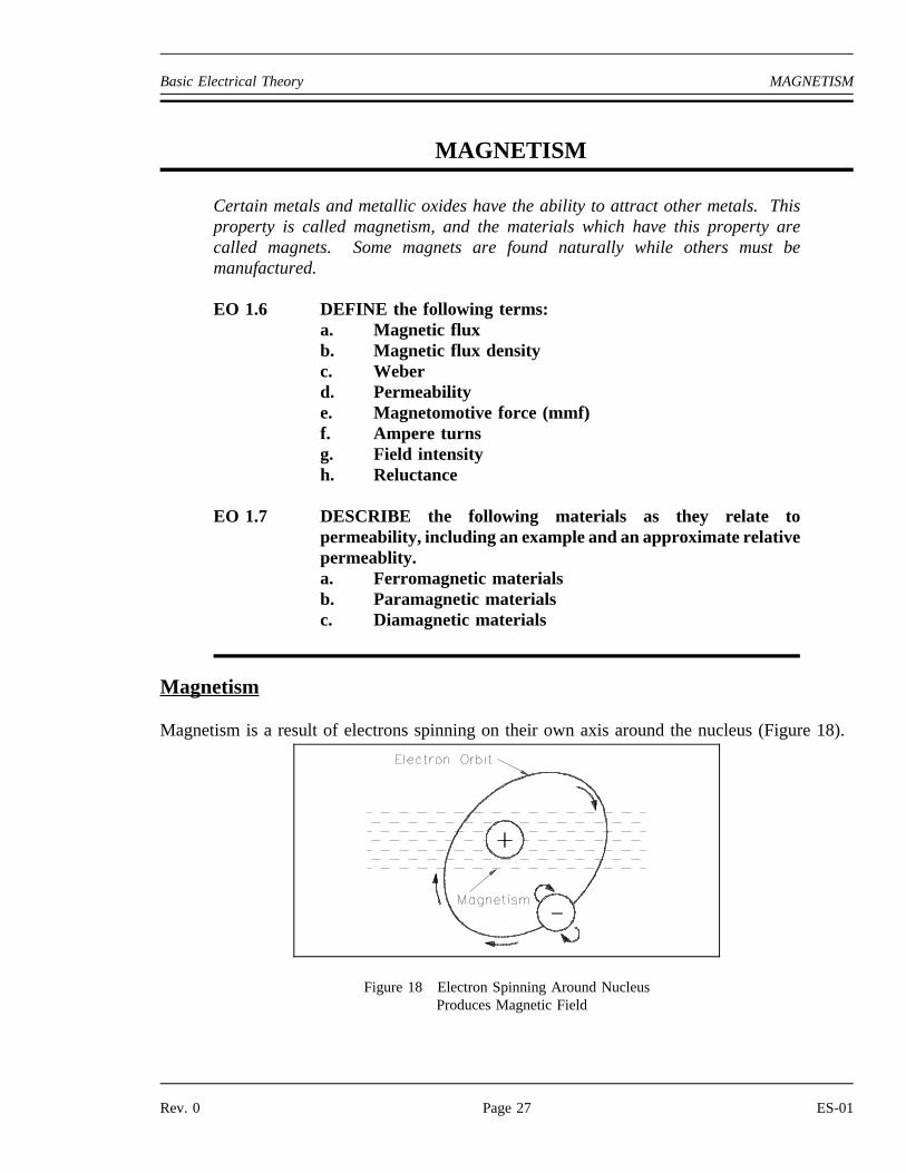
Magnetism is a result of electrons spinning on their own axis around the nucleus (Figure 18).
Figure 18 Electron Spinning Around NucleusProduces Magnetic Field
Rev. 0 Page 27 ES-01
MAGNETISM Basic Electrical Theory
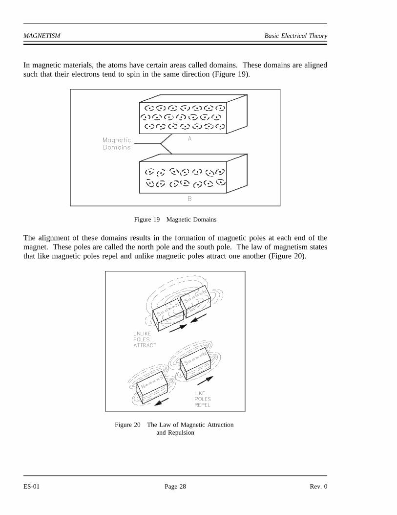
In magnetic materials, the atoms have certain areas called domains. These domains are alignedsuch that their electrons tend to spin in the same direction (Figure 19).
Figure 19 Magnetic Domains
The alignment of these domains results in the formation of magnetic poles at each end of themagnet. These poles are called the north pole and the south pole. The law of magnetism statesthat like magnetic poles repel and unlike magnetic poles attract one another (Figure 20).
Figure 20 The Law of Magnetic Attractionand Repulsion
ES-01 Page 28 Rev. 0
Basic Electrical Theory MAGNETISM
Magnetic Flux
The group of magnetic field lines emitted outward from the north pole of a magnet is calledmagnetic flux. The symbol for magnetic flux isΦ (phi).
The SI unit of magnetic flux is the weber (Wb). Oneweberis equal to 1 x 10⁸ magnetic fieldlines.
Example: If a magnetic flux (Φ) has 5,000 lines, find the number of webers.
Φ 5000 lines
1 x 10⁸ lines/Wb
5 x 10³
10850 x 10 6 Wb 50 µWb
Magnetic Flux Density
Magnetic flux densityis the amount of magnetic flux per unit area of a section, perpendicular tothe direction of flux. Equation (1-11) is the mathematical representation of magnetic fluxdensity.
(1-11)B ΦA
where
B = magnetic flux density in teslas (T)
Φ = magnetic flux in webers (Wb)
A = area in square meters (m2)
The result is that the SI unit for flux density is webers per square meter . One weber per
Wb
m2
square meter equals one tesla.
Rev. 0 Page 29 ES-01
MAGNETISM Basic Electrical Theory
Example: Find the flux density in teslas, when the flux is 800 µWb and the area is 0.004 m2.
Given: Φ = 800 µWb = 8 x 10⁻⁴ Wb
A = 0.0004 m2 = 4 x 10⁻⁴ m2
B ΦA
8 x 10 4 Wb
4 x 10 4 m22 Wb/m2
Magnetic Materials
Magnetic materialsare those materials that can be either attracted or repelled by a magnet andcan be magnetized themselves. The most commonly used magnetic materials are iron and steel.A permanent magnet is made of a very hard magnetic material, such as cobalt steel, that retainsits magnetism for long periods of time when the magnetizing field is removed. A temporarymagnet is a material that will not retain its magnetism when the field is removed.
Permeability(µ) refers to the ability of a material to concentrate magnetic lines of flux. Thosematerials that can be easily magnetized are considered to have a high permeability. Relativepermeability is the ratio of the permeability of a material to the permeability of a vacuum (µo).The symbol for relative permeability is µR (mu).
µR = where µo = 4π10-7H/m (1-12)µo
µo
Magnetic materials are classified as either magnetic or nonmagnetic based on the highly magneticproperties of iron. Because even weak magnetic materials may serve a useful purpose in someapplications, classification includes the three groups described below.
Ferromagnetic Materials: Some of the ferromagnetic materials used are iron, steel, nickel,cobalt, and the commercial alloys, alnico and peralloy. Ferrites are nonmagnetic, but have theferromagnetic properties of iron. Ferrites are made of ceramic material and have relativepermeabilities that range from 50 to 200. They are commonly used in the coils for RF (radiofrequency) transformers.
Paramagnetic Materials: These are materials such as aluminum, platinum, manganese, andchromium. These materials have a relative permeability of slightly more than one.
Diamagnetic Materials: These are materials such as bismuth, antimony, copper, zinc, mercury,gold, and silver. These materials have a relative permeability of less than one.
ES-01 Page 30 Rev. 0
Basic Electrical Theory MAGNETISM
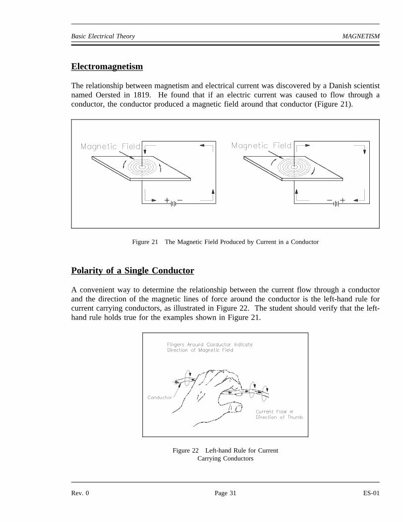
Electromagnetism
The relationship between magnetism and electrical current was discovered by a Danish scientistnamed Oersted in 1819. He found that if an electric current was caused to flow through aconductor, the conductor produced a magnetic field around that conductor (Figure 21).
Figure 21 The Magnetic Field Produced by Current in a Conductor
Polarity of a Single Conductor
A convenient way to determine the relationship between the current flow through a conductorand the direction of the magnetic lines of force around the conductor is the left-hand rule forcurrent carrying conductors, as illustrated in Figure 22. The student should verify that the left-hand rule holds true for the examples shown in Figure 21.
Figure 22 Left-hand Rule for CurrentCarrying Conductors
Rev. 0 Page 31 ES-01
MAGNETISM Basic Electrical Theory
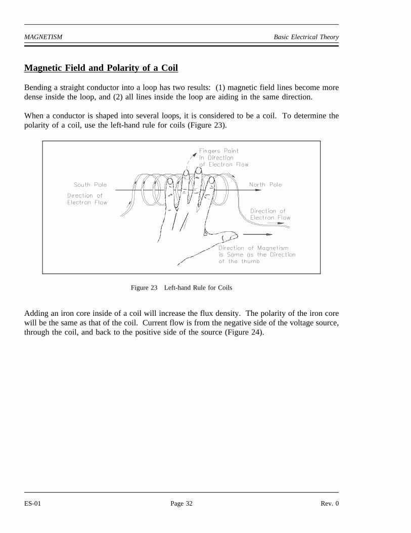
Magnetic Field and Polarity of a Coil
Bending a straight conductor into a loop has two results: (1) magnetic field lines become moredense inside the loop, and (2) all lines inside the loop are aiding in the same direction.
When a conductor is shaped into several loops, it is considered to be a coil. To determine thepolarity of a coil, use the left-hand rule for coils (Figure 23).
Figure 23 Left-hand Rule for Coils
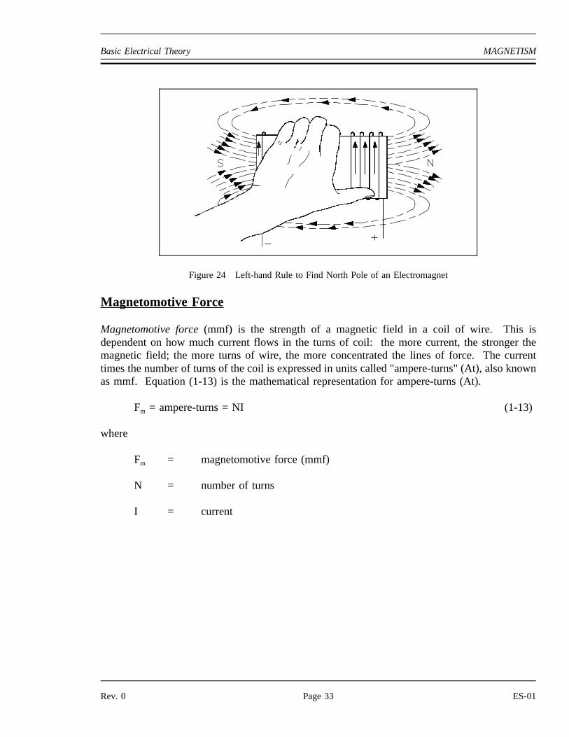
Adding an iron core inside of a coil will increase the flux density. The polarity of the iron corewill be the same as that of the coil. Current flow is from the negative side of the voltage source,through the coil, and back to the positive side of the source (Figure 24).
ES-01 Page 32 Rev. 0
Basic Electrical Theory MAGNETISM
Figure 24 Left-hand Rule to Find North Pole of an Electromagnet
Magnetomotive Force
Magnetomotive force(mmf) is the strength of a magnetic field in a coil of wire. This isdependent on how much current flows in the turns of coil: the more current, the stronger themagnetic field; the more turns of wire, the more concentrated the lines of force. The currenttimes the number of turns of the coil is expressed in units called "ampere-turns" (At), also knownas mmf. Equation (1-13) is the mathematical representation for ampere-turns (At).
Fm = ampere-turns = NI (1-13)
where
Fm = magnetomotive force (mmf)
N = number of turns
I = current
Rev. 0 Page 33 ES-01
MAGNETISM Basic Electrical Theory
Example: Calculate the ampere-turns for a coil with 1000 turns and a 5 mAcurrent.
N = 1000 turns and I = 5 mA
substitute
N = 1000 turns and I = 5 x 10⁻³
NI = 1000 (5 x 10⁻³) = 5 At
Field Intensity
When a coil with a certain number of ampere-turns is stretched to twice its length, the magneticfield intensity, or the concentration of its magnetic lines of force, will be half as great. Therefore,field intensity depends on the length of the coil. Equation (1-14) is the mathematicalrepresentation for field intensity, which is related to magnetomotive force as shown.
(1-14)HFM
LNIL
where
H = field intensity, Atm
NI = ampere-turns (At)
L = length between poles of coil (m)
FM = Magnetomotive force (mmf)
Example 1: Find field intensity of an 80 turn, 20 cm coil, with 6A of current.
Solution:
N = 80, I = 6A, and NI = 480 At
H 480 At0.2 m
2400 Atm
Example 2: If the same coil in Example 1 were to be stretched to 40 cm with wire length andcurrent remaining the same, find the new value of field intensity.
Solution:
N = 80, I = 6A, and NI = 480 At
H 480 At0.4 m
1200 Atm
ES-01 Page 34 Rev. 0
Basic Electrical Theory MAGNETISM
Example 3: The 20 cm coil used in Example 1 with the same current is now wound aroundan iron core 40 cm in length. Find the field intensity.
Solution:
N = 80, I = 6A, and NI = 480 At
H 480 At0.4 m
1200 Atm
Note that field intensity for Examples 2 and 3 is the same.
Figure 25 Different Physical Forms of Electromagnets
Reluctance
Opposition to the production of flux in a material is calledreluctance, which corresponds toresistance. The symbol for reluctance is R, and it has the units of ampere-turns per weber(At/wb).
Reluctance is related to magnetomotive force, mmf, and flux,Φ, by the relationship shown inequation (1-15).
(1-15)R mmfΦ
Reluctance is inversely proportional to permeability (µ). Iron cores have high permeability and,therefore, low reluctance. Air has a low permeability and, therefore, a high reluctance.
Rev. 0 Page 35 ES-01
MAGNETISM Basic Electrical Theory
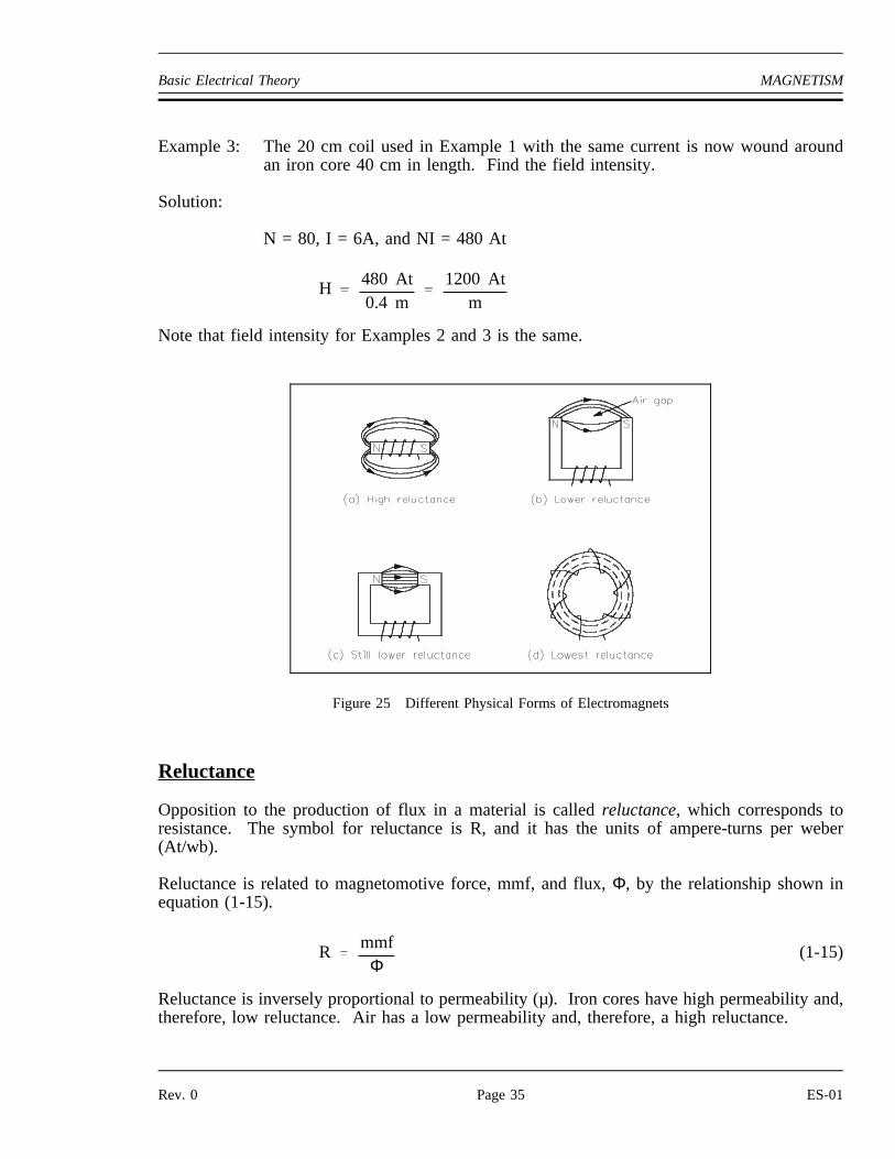
Generally, different types of materials have different values of reluctance (Figure 25). Air gapis the air space between two poles of a magnet. Since air has a very high reluctance, the sizeof the air gap affects the value of reluctance: the shorter the air gap, the stronger the field in thegap. Air is nonmagnetic and will not concentrate magnetic lines. The larger air gap onlyprovides space for the magnetic lines to spread out.
Summary
The important information contained in this chapter is summarized below.
Magnetism Summary
Magnetic flux - group of magnetic field lines that are emitted outward from thenorth pole of a magnet
Magnetic flux density - amount of magnetic flux per unit area of a section,perpendicular to the direction of the flux
Weber - measure of magnetic flux
Permeability - ability of a material to concentrate magnetic lines of flux
Ferromagnetic materials - iron, steel, nickel, cobalt, and commercial alloys withrelative permeability ranging from 50-200
Paramagnetic materials - aluminum, platinum, manganese, and chromium withrelative permeability of slightly more than one
Diamagnetic materials - bismuth, antimony, copper, zinc, mercury, gold, andsilver with relative permeability of less than one
Magnetomotive force (mmf) - strength of a magnetic field in a coil of wiredependent on current flowing through coil
Ampere turns - current flowing through a coil times the number of turns in thecoil
Field intensity - identifies the magnetic flux density per unit length of a coil
Reluctance - opposition to the production of flux in a material
ES-01 Page 36 Rev. 0
Basic Electrical Theory MAGNETIC CIRCUITS
MAGNETIC CIRCUITS
What is a magnetic circuit? To better understand magnetic circuits, a basicunderstanding of the physical qualities of magnetic circuits will be necessary.
EO 1.8 EXPLAIN the physical qualities of a simple magnetic circuit,including relationships of qualities and units of measurements.
EO 1.9 Given the physical qualities of a simple magnetic circuit,CALCULATE the unknown values.
EO 1.10 DESCRIBE the shape and components of a BH magnetizationcurve.
EO 1.11 EXPLAIN the cause of hysteresis losses.
EO 1.12 Given Faraday’s Law of induced voltage:a. DESCRIBE how varying parameters affect induced voltage.b. CALCULATE voltage induced in a conductor moving through
a magnetic field.
EO 1.13 STATE Lenz’s Law of induction.
Magnetic Circuits
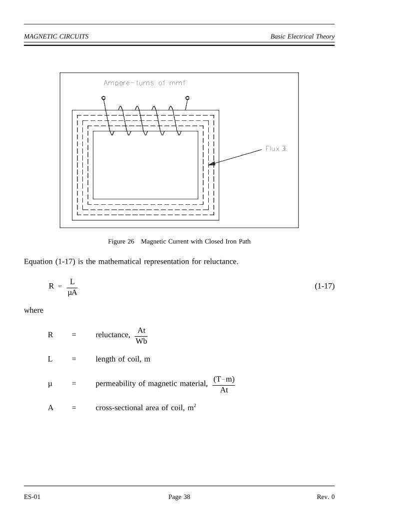
A magnetic circuit can be compared with an electric current in which EMF, or voltage, producesa current flow. The ampere-turns (NI), or the magnetomotive force (Fm or mmf), will producea magnetic fluxΦ (Figure 26). The mmf can be compared with EMF, and the flux (Φ) can becompared to current. Equation (1-16) is the mathematical representation of magnetomotive force
derived using Ohm’s Law, .I ER
Φ = (1-16)Fm
Rmmf
R
where
Φ = magnetic flux, Wb
Fm = magnetomotive force (mmf), At
R = reluctance, AtWb
Rev. 0 Page 37 ES-01
MAGNETIC CIRCUITS Basic Electrical Theory
Figure 26 Magnetic Current with Closed Iron Path
Equation (1-17) is the mathematical representation for reluctance.
(1-17)R LµA
where
R = reluctance, AtWb
L = length of coil, m
µ = permeability of magnetic material,(T m)At
A = cross-sectional area of coil, m2
ES-01 Page 38 Rev. 0
Basic Electrical Theory MAGNETIC CIRCUITS
Example: A coil has an mmf of 600 At, and a reluctance of 3 x 10⁶ At/Wb.Find the total fluxΦ.
Solution:
Φ mmfR
Φ 600At
3 x 10⁶ At/Wb200 x 106 Wb 200µWb
BH Magnetization Curve
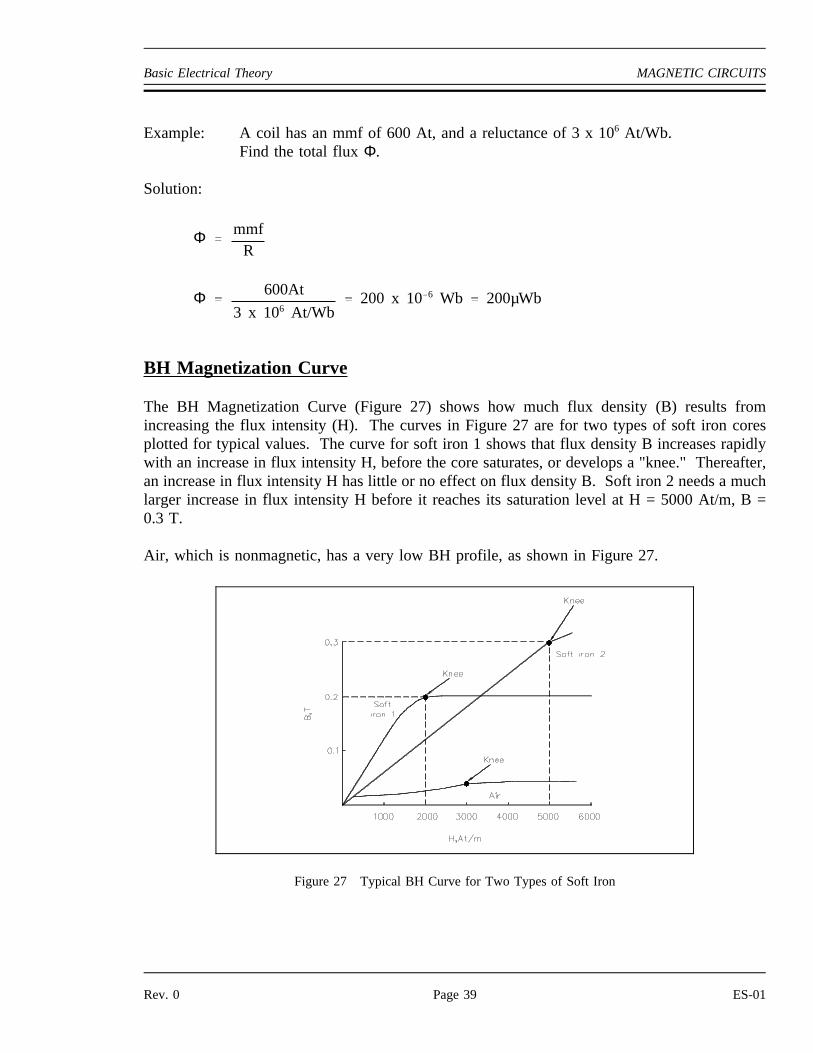
The BH Magnetization Curve (Figure 27) shows how much flux density (B) results fromincreasing the flux intensity (H). The curves in Figure 27 are for two types of soft iron coresplotted for typical values. The curve for soft iron 1 shows that flux density B increases rapidlywith an increase in flux intensity H, before the core saturates, or develops a "knee." Thereafter,an increase in flux intensity H has little or no effect on flux density B. Soft iron 2 needs a muchlarger increase in flux intensity H before it reaches its saturation level at H = 5000 At/m, B =0.3 T.
Air, which is nonmagnetic, has a very low BH profile, as shown in Figure 27.
Figure 27 Typical BH Curve for Two Types of Soft Iron
Rev. 0 Page 39 ES-01
MAGNETIC CIRCUITS Basic Electrical Theory
The permeability (µ) of a magnetic material is the ratio of B to H. Equation (1-18) is themathematical representation for magnetic material permeability.
(1-18)µ BH
The average value of permeability is measured where the saturation point, or knee, is firstestablished. Figure 27 shows that the normal or average permeability for the two irons asfollows.
µ soft iron 1 = = = 1 x 10⁻⁴BH
0.22000
(T m)At
µ soft iron 2 = = 6 x 10⁻⁵BH
0.35000
(T m )At
In SI units, the permeability of a vacuum is µo = 4 π x 10-7 H/m or 1.26 x 10⁻⁶ or T-m/At. Inorder to calculate permeability, the value of relative permeability µr must be multiplied by µo.Equation (1-18) is the mathematical representation for permeability.
µ = µr x µo (1-18)
Example: Find the permeability of a material that has a relative permeability of 100.
µ = µr x µo = 100 (1.26 x 10⁻⁶)
= 126 x 10-6 (T m)At
Hysteresis
When current in a coil reverses direction thousands of times per second, hysteresis can causeconsiderable loss of energy.Hysteresisis defined as "a lagging behind." The magnetic flux inan iron core lags behind the magnetizing force.
ES-01 Page 40 Rev. 0
Basic Electrical Theory MAGNETIC CIRCUITS
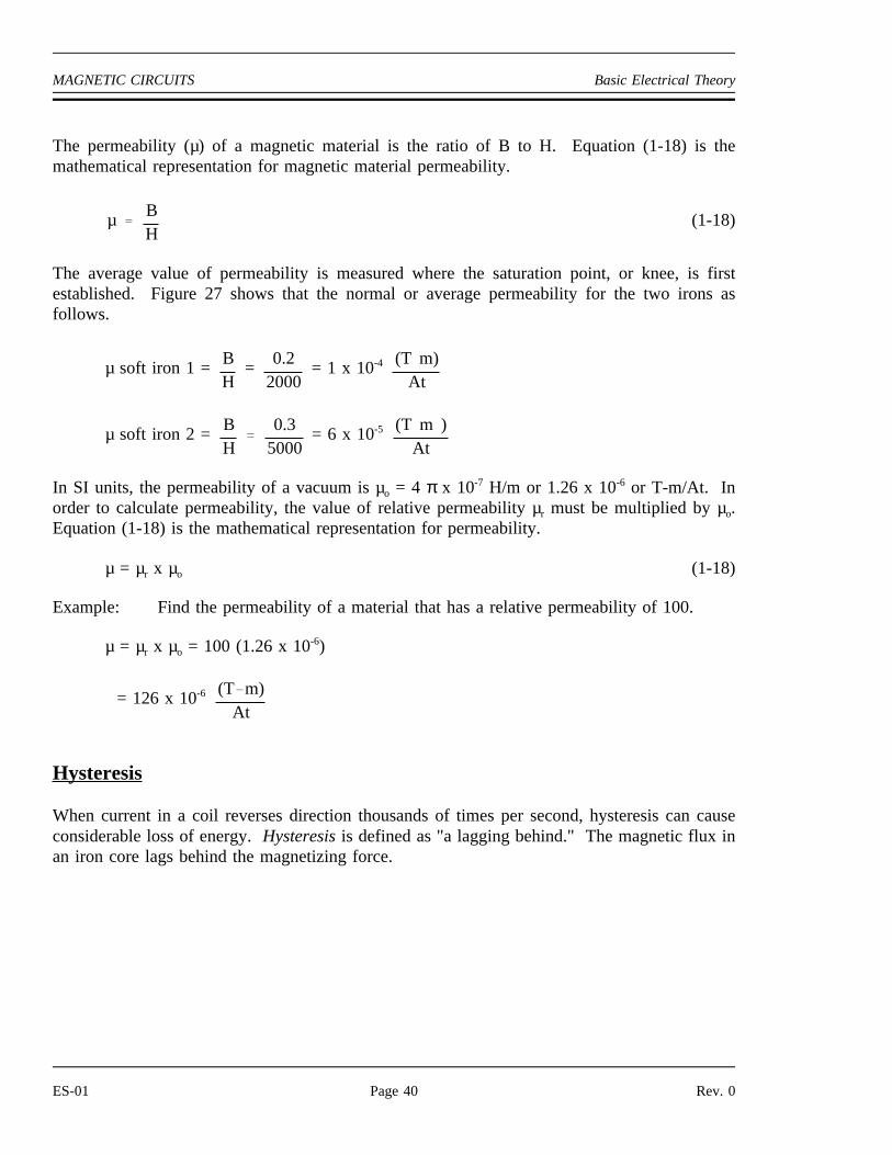
The hysteresis loop is a series of
Figure 28 Hysteresis Loop for Magnetic Materials
c u r v e s t h a t s h o w s t h echaracteristics of a magneticmaterial (Figure 28). Oppositedirections of current will result inopposite directions of fluxintensity shown as +H and -H.Opposite polarities are also shownfor flux density as +B or -B.Current starts at the center (zero)when unmagnetized. Positive Hvalues increase B to the saturationpoint, or +Bmax, as shown by thedashed line. Then H decreases tozero, but B drops to the value ofBr due to hysteresis. By reversingthe original current, H nowbecomes negative. B drops tozero and continues on to -Bmax. Asthe -H values decrease (lessnegative), B is reduced to -Br
when H is zero. With a positiveswing of current, H once againbecomes positive, producingsaturation at +Bmax. The hysteresisloop is completed. The loop doesnot return to zero because ofhysteresis.
The value of +Br or -Br, which is the flux density remaining after the magnetizing force is zero,is called theretentivityof that magnetic material. The value of -Hc, which is the force that mustbe applied in the reverse direction to reduce flux density to zero, is called thecoercive forceofthe material.
The greater the area inside the hysteresis loop, the larger the hysteresis losses.
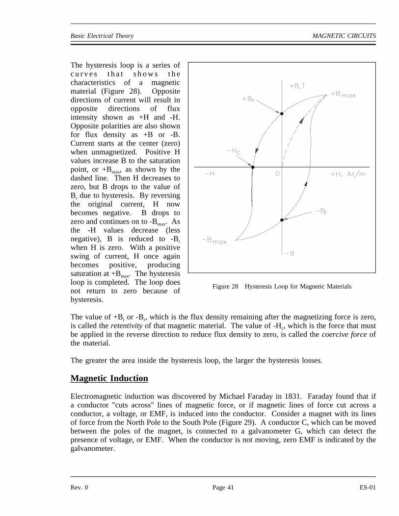
Magnetic Induction
Electromagnetic induction was discovered by Michael Faraday in 1831. Faraday found that ifa conductor "cuts across" lines of magnetic force, or if magnetic lines of force cut across aconductor, a voltage, or EMF, is induced into the conductor. Consider a magnet with its linesof force from the North Pole to the South Pole (Figure 29). A conductor C, which can be movedbetween the poles of the magnet, is connected to a galvanometer G, which can detect thepresence of voltage, or EMF. When the conductor is not moving, zero EMF is indicated by thegalvanometer.
Rev. 0 Page 41 ES-01
MAGNETIC CIRCUITS Basic Electrical Theory
If the conductor is moving outside the magnetic field at position 1, zero EMF is still indicatedby the galvanometer. When the conductor is moved to position 2, the lines of magnetic forcewill be cut by the conductor, and the galvanometer will deflect to point A. Moving theconductor to position 3 will cause the galvanometer to return to zero. By reversing the directionin which the conductor is moved (3 to 1), the same results are noticed, but of opposite polarity.If we hold the conductor stationary in the magnetic lines of force, at position 2, the galvanometerindicates zero. This fact shows that there must be relative motion between the conductor and themagnetic lines of force in order to induce an EMF.
Figure 29 Induced EMF
The most important application of relative motion is seen in electric generators. In a DCgenerator, electromagnets are arranged in a cylindrical housing. Conductors, in the form of coils,are rotated on a core such that the coils continually cut the magnetic lines of force. The resultis a voltage induced in each of the conductors. These conductors are connected in series, andthe induced voltages are added together to produce the generator’s output voltage.
Faraday’s Law of Induced Voltage
The magnitude of the induced voltage depends on two factors: (1) the number of turns of a coil,and (2) how fast the conductor cuts across the magnetic lines of force, or flux. Equation (1-20)is the mathematical representation for Faraday’s Law of Induced Voltage.
Vind = (1-20)N
∆Φ∆t
where
Vind = induced voltage, V
ES-01 Page 42 Rev. 0
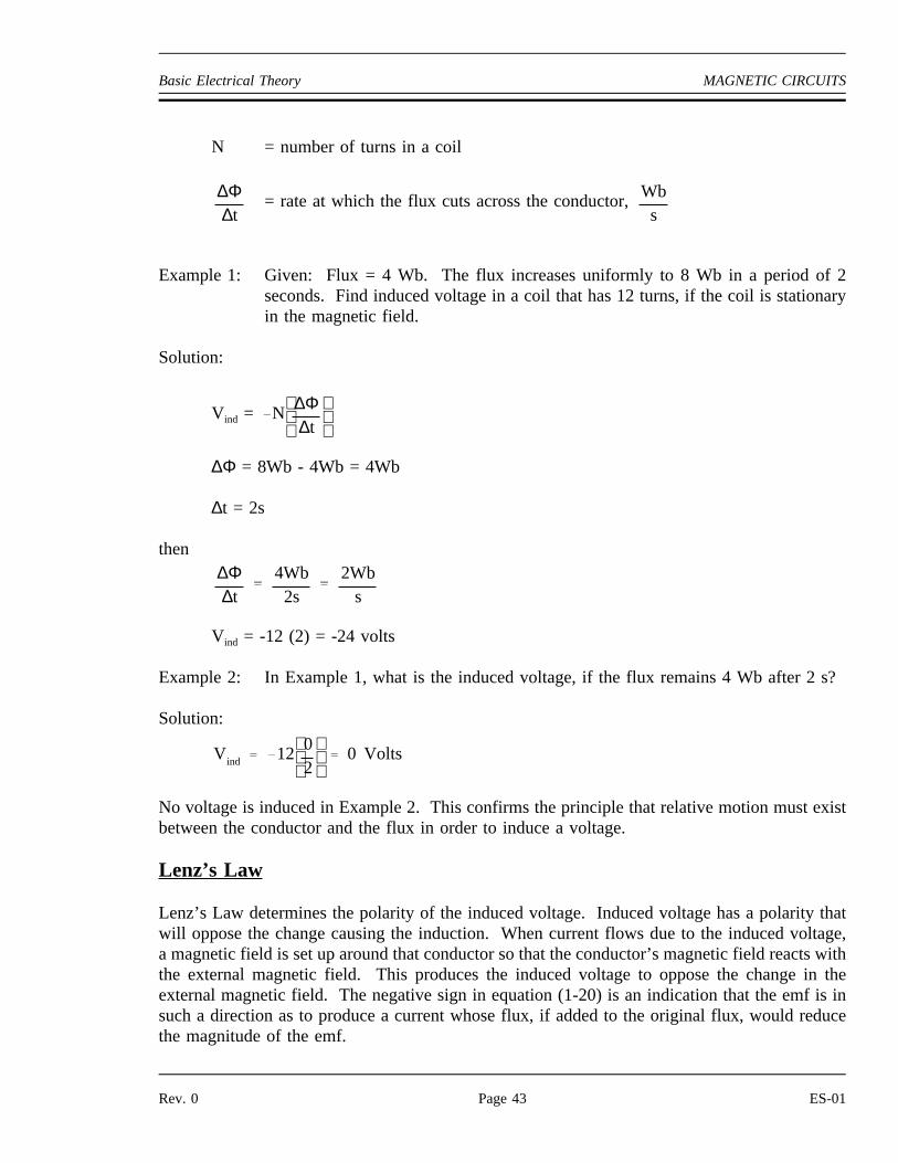
Basic Electrical Theory MAGNETIC CIRCUITS
N = number of turns in a coil
= rate at which the flux cuts across the conductor,∆Φ∆t
Wbs
Example 1: Given: Flux = 4 Wb. The flux increases uniformly to 8 Wb in a period of 2seconds. Find induced voltage in a coil that has 12 turns, if the coil is stationaryin the magnetic field.
Solution:
Vind = N
∆Φ∆t
∆Φ = 8Wb - 4Wb = 4Wb
∆t = 2s
then∆Φ∆t
4Wb2s
2Wbs
Vind = -12 (2) = -24 volts
Example 2: In Example 1, what is the induced voltage, if the flux remains 4 Wb after 2 s?
Solution:
Vind 12
02
0 Volts
No voltage is induced in Example 2. This confirms the principle that relative motion must existbetween the conductor and the flux in order to induce a voltage.
Lenz’s Law
Lenz’s Law determines the polarity of the induced voltage. Induced voltage has a polarity thatwill oppose the change causing the induction. When current flows due to the induced voltage,a magnetic field is set up around that conductor so that the conductor’s magnetic field reacts withthe external magnetic field. This produces the induced voltage to oppose the change in theexternal magnetic field. The negative sign in equation (1-20) is an indication that the emf is insuch a direction as to produce a current whose flux, if added to the original flux, would reducethe magnitude of the emf.
Rev. 0 Page 43 ES-01
MAGNETIC CIRCUITS Basic Electrical Theory
Summary
The important information contained in this chapter is summarized below.
Magnetic Circuits Summary
Simple magnetic circuit magnetic flux (Φ) is proportional to themagnetomotive force (Fm) and indirectly proportional to the reluctance (R)in a circuit.
Φ (Wb)Fm (At)
R
AtWb
A BH magnetization curve shows how much magnetic flux density (B)results from increasing magnetic flux intensity. The "knee" identifies thepoint where increasing flux intensity (H) results in a minimal increase influx density (B).
Hysteresis losses are caused by reversing current direction thousands oftimes in a coil.
Faraday’s Law of Induced Voltage depends on the number of turns of a coiland how fast the conductor cuts across the magnetic lines of force or flux.
Vind N ∆Φ∆t
Lenz’s Law states that an induced voltage will have a polarity that willoppose the magnetic field that caused the induced voltage.
ES-01 Page 44 Rev. 0
Basic Electrical Theory ELECTRICAL SYMBOLS
ELECTRICAL SYMBOLS
To read and interpret electrical system diagrams and schematics, one must bethoroughly familiar with the many symbols used. Once these symbols aremastered, most electrical diagrams and schematics will be understood withrelative ease.
EO 1.14 Given a standard electrical symbol, IDENTIFY the component that thesymbol represents. The symbols will be for the following components:
a. Resistor m. Fuseb. Capacitor n. Junctionc. Inductor o. AC voltage sourced. Relay p. Voltmetere. Contacts q. Ammeterf. Breaker r. Wattmeterg. Switch s. Relay operated contactsh. Transistor t. Potential transformeri. Rheostat u. Current transformerj. Diode v. Wye (Y) connectionk. Ground connections w. Delta (∆) connectionl. Vacuum tube x. Light bulb
y. Battery
Symbols
The symbols for the various electrical components that will appear on electrical diagrams andschematics are shown in Figure 30.
Rev. 0 Page 45 ES-01
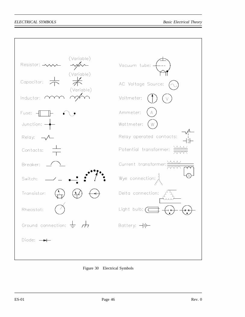
ELECTRICAL SYMBOLS Basic Electrical Theory
Figure 30 Electrical Symbols
ES-01 Page 46 Rev. 0
Basic Electrical Theory ELECTRICAL SYMBOLS
Summary
The important information contained in this chapter is summarized below.
Electrical Symbols Summary
To read and interpret electrical system diagrams and schematics, one must bethoroughly familiar with the many symbols used. Once these symbols aremastered, most electrical diagrams and schematics will be understood withrelative ease.
Rev. 0 Page 47 ES-01
ELECTRICAL SYMBOLS Basic Electrical Theory
Intentionally Left Blank
ES-01 Page 48 Rev. 0
Appendix AMetric System and Powers of Ten
BASIC ELECTRICAL THEORY

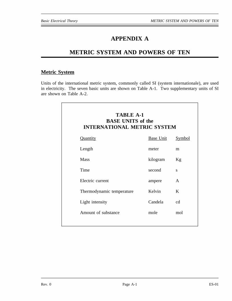
Basic Electrical Theory METRIC SYSTEM AND POWERS OF TEN
APPENDIX A
METRIC SYSTEM AND POWERS OF TEN
Metric System
Units of the international metric system, commonly called SI (system internationale), are usedin electricity. The seven basic units are shown on Table A-1. Two supplementary units of SIare shown on Table A-2.
TABLE A-1BASE UNITS of the
INTERNATIONAL METRIC SYSTEM
Quantity Base Unit Symbol
Length meter m
Mass kilogram Kg
Time second s
Electric current ampere A
Thermodynamic temperature Kelvin K
Light intensity Candela cd
Amount of substance mole mol
Rev. 0 Page A-1 ES-01
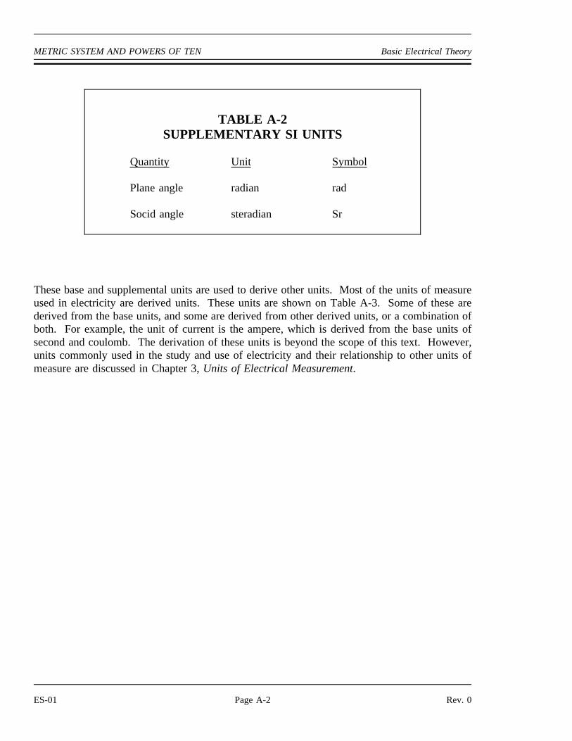
METRIC SYSTEM AND POWERS OF TEN Basic Electrical Theory
TABLE A-2SUPPLEMENTARY SI UNITS
Quantity Unit Symbol
Plane angle radian rad
Socid angle steradian Sr
These base and supplemental units are used to derive other units. Most of the units of measureused in electricity are derived units. These units are shown on Table A-3. Some of these arederived from the base units, and some are derived from other derived units, or a combination ofboth. For example, the unit of current is the ampere, which is derived from the base units ofsecond and coulomb. The derivation of these units is beyond the scope of this text. However,units commonly used in the study and use of electricity and their relationship to other units ofmeasure are discussed in Chapter 3,Units of Electrical Measurement.
ES-01 Page A-2 Rev. 0
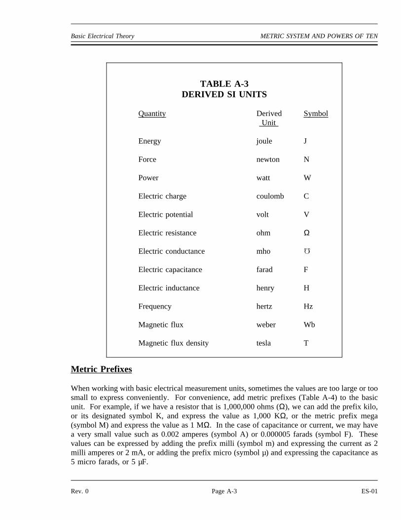
Basic Electrical Theory METRIC SYSTEM AND POWERS OF TEN
TABLE A-3DERIVED SI UNITS
Quantity Derived SymbolUnit
Energy joule J
Force newton N
Power watt W
Electric charge coulomb C
Electric potential volt V
Electric resistance ohm Ω
Electric conductance mho
Electric capacitance farad F
Electric inductance henry H
Frequency hertz Hz
Magnetic flux weber Wb
Magnetic flux density tesla T
Metric Prefixes
When working with basic electrical measurement units, sometimes the values are too large or toosmall to express conveniently. For convenience, add metric prefixes (Table A-4) to the basicunit. For example, if we have a resistor that is 1,000,000 ohms (Ω), we can add the prefix kilo,or its designated symbol K, and express the value as 1,000 KΩ, or the metric prefix mega(symbol M) and express the value as 1 MΩ. In the case of capacitance or current, we may havea very small value such as 0.002 amperes (symbol A) or 0.000005 farads (symbol F). Thesevalues can be expressed by adding the prefix milli (symbol m) and expressing the current as 2milli amperes or 2 mA, or adding the prefix micro (symbol µ) and expressing the capacitance as5 micro farads, or 5 µF.
Rev. 0 Page A-3 ES-01
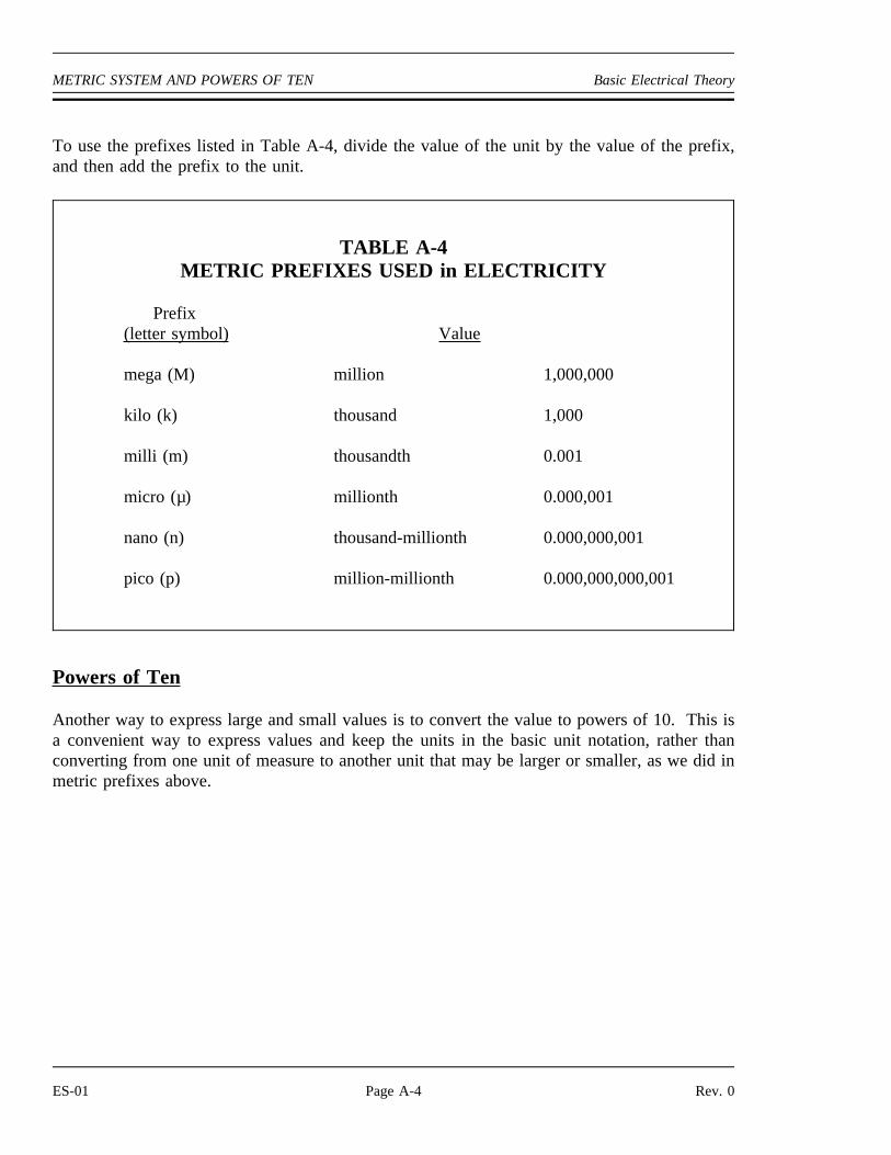
METRIC SYSTEM AND POWERS OF TEN Basic Electrical Theory
To use the prefixes listed in Table A-4, divide the value of the unit by the value of the prefix,and then add the prefix to the unit.
TABLE A-4METRIC PREFIXES USED in ELECTRICITY
Prefix(letter symbol) Value
mega (M) million 1,000,000
kilo (k) thousand 1,000
milli (m) thousandth 0.001
micro (µ) millionth 0.000,001
nano (n) thousand-millionth 0.000,000,001
pico (p) million-millionth 0.000,000,000,001
Powers of Ten
Another way to express large and small values is to convert the value to powers of 10. This isa convenient way to express values and keep the units in the basic unit notation, rather thanconverting from one unit of measure to another unit that may be larger or smaller, as we did inmetric prefixes above.
ES-01 Page A-4 Rev. 0
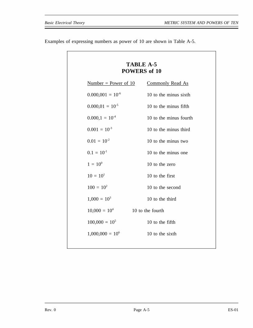
Basic Electrical Theory METRIC SYSTEM AND POWERS OF TEN
Examples of expressing numbers as power of 10 are shown in Table A-5.
TABLE A-5POWERS of 10
Number = Power of 10 Commonly Read As
0.000,001 = 10-6 10 to the minus sixth
0.000,01 = 10-5 10 to the minus fifth
0.000,1 = 10-4 10 to the minus fourth
0.001 = 10-3 10 to the minus third
0.01 = 10-2 10 to the minus two
0.1 = 10-1 10 to the minus one
1 = 100 10 to the zero
10 = 101 10 to the first
100 = 102 10 to the second
1,000 = 103 10 to the third
10,000 = 104 10 to the fourth
100,000 = 105 10 to the fifth
1,000,000 = 106 10 to the sixth
Rev. 0 Page A-5 ES-01
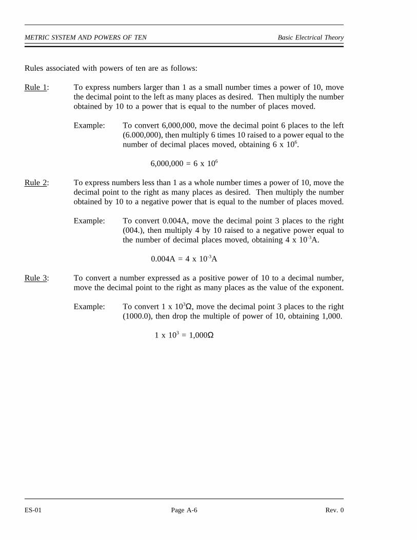
METRIC SYSTEM AND POWERS OF TEN Basic Electrical Theory
Rules associated with powers of ten are as follows:
Rule 1: To express numbers larger than 1 as a small number times a power of 10, movethe decimal point to the left as many places as desired. Then multiply the numberobtained by 10 to a power that is equal to the number of places moved.
Example: To convert 6,000,000, move the decimal point 6 places to the left(6.000,000), then multiply 6 times 10 raised to a power equal to thenumber of decimal places moved, obtaining 6 x 10⁶.
6,000,000 = 6 x 10⁶
Rule 2: To express numbers less than 1 as a whole number times a power of 10, move thedecimal point to the right as many places as desired. Then multiply the numberobtained by 10 to a negative power that is equal to the number of places moved.
Example: To convert 0.004A, move the decimal point 3 places to the right(004.), then multiply 4 by 10 raised to a negative power equal tothe number of decimal places moved, obtaining 4 x 10⁻³A.
0.004A = 4 x 10⁻³A
Rule 3: To convert a number expressed as a positive power of 10 to a decimal number,move the decimal point to the right as many places as the value of the exponent.
Example: To convert 1 x 10³Ω, move the decimal point 3 places to the right(1000.0), then drop the multiple of power of 10, obtaining 1,000.
1 x 103 = 1,000Ω
ES-01 Page A-6 Rev. 0
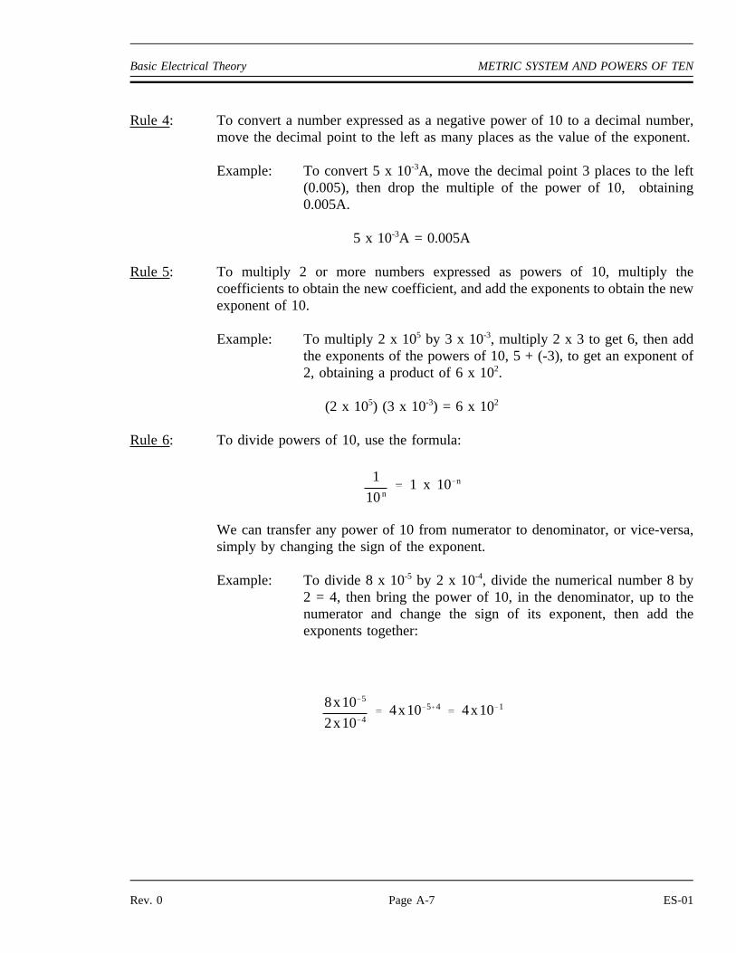
Basic Electrical Theory METRIC SYSTEM AND POWERS OF TEN
Rule 4: To convert a number expressed as a negative power of 10 to a decimal number,move the decimal point to the left as many places as the value of the exponent.
Example: To convert 5 x 10⁻³A, move the decimal point 3 places to the left(0.005), then drop the multiple of the power of 10, obtaining0.005A.
5 x 10⁻³A = 0.005A
Rule 5: To multiply 2 or more numbers expressed as powers of 10, multiply thecoefficients to obtain the new coefficient, and add the exponents to obtain the newexponent of 10.
Example: To multiply 2 x 105 by 3 x 10-3, multiply 2 x 3 to get 6, then addthe exponents of the powers of 10, 5 + (-3), to get an exponent of2, obtaining a product of 6 x 10².
(2 x 10⁵) (3 x 10⁻³) = 6 x 10²
Rule 6: To divide powers of 10, use the formula:
1
10n1 x 10 n
We can transfer any power of 10 from numerator to denominator, or vice-versa,simply by changing the sign of the exponent.
Example: To divide 8 x 10-5 by 2 x 10-4, divide the numerical number 8 by2 = 4, then bring the power of 10, in the denominator, up to thenumerator and change the sign of its exponent, then add theexponents together:
8x10 5
2x10 44x10 5 4 4x10 1
Rev. 0 Page A-7 ES-01
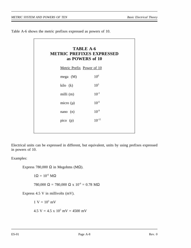
METRIC SYSTEM AND POWERS OF TEN Basic Electrical Theory
Table A-6 shows the metric prefixes expressed as powers of 10.
TABLE A-6METRIC PREFIXES EXPRESSED
as POWERS of 10
Metric Prefix Power of 10
mega (M) 106
kilo (k) 103
milli (m) 10-3
micro (µ) 10-6
nano (n) 10-9
pico (p) 10-12
Electrical units can be expressed in different, but equivalent, units by using prefixes expressedin powers of 10.
Examples:
Express 780,000Ω in Megohms (MΩ).
1Ω = 10-6 MΩ
780,000Ω = 780,000Ω x 10-6 = 0.78 MΩ
Express 4.5 V in millivolts (mV).
1 V = 103 mV
4.5 V = 4.5 x 10³ mV = 4500 mV
ES-01 Page A-8 Rev. 0
Basic Electrical Theory METRIC SYSTEM AND POWERS OF TEN
Express 0.015 A in milliamperes (mA).
1 A = 103 mA
0.015 A = 0.015 x 103 = 15 mA
Rev. 0 Page A-9 ES-01
METRIC SYSTEM AND POWERS OF TEN Basic Electrical Theory
Intentionally Left Blank
ES-01 Page A-10 Rev. 0
Department of EnergyFundamentals Handbook
ELECTRICAL SCIENCEModule 2
Basic DC Theory

Basic DC Theory TABLE OF CONTENTS
TABLE OF CONTENTS
LIST OF FIGURES . . . . . . . . . . . . . . . . . . . . . . . . . . . . . . . . . . . . . . . . . . . . . . . . . . iii
LIST OF TABLES . . . . . . . . . . . . . . . . . . . . . . . . . . . . . . . . . . . . . . . . . . . . . . . . . . . vi
REFERENCES . . . . . . . . . . . . . . . . . . . . . . . . . . . . . . . . . . . . . . . . . . . . . . . . . . . . vii
OBJECTIVES . . . . . . . . . . . . . . . . . . . . . . . . . . . . . . . . . . . . . . . . . . . . . . . . . . . . .viii
DC SOURCES . . . . . . . . . . . . . . . . . . . . . . . . . . . . . . . . . . . . . . . . . . . . . . . . . . . . . 1
Batteries. . . . . . . . . . . . . . . . . . . . . . . . . . . . . . . . . . . . . . . . . . . . . . . . . . . . . 1DC Generator. . . . . . . . . . . . . . . . . . . . . . . . . . . . . . . . . . . . . . . . . . . . . . . . . 2Thermocouples. . . . . . . . . . . . . . . . . . . . . . . . . . . . . . . . . . . . . . . . . . . . . . . . 3Rectifiers . . . . . . . . . . . . . . . . . . . . . . . . . . . . . . . . . . . . . . . . . . . . . . . . . . . . 5Forward Bias . . . . . . . . . . . . . . . . . . . . . . . . . . . . . . . . . . . . . . . . . . . . . . . . . 5Reverse Bias. . . . . . . . . . . . . . . . . . . . . . . . . . . . . . . . . . . . . . . . . . . . . . . . . . 7Half-Wave Rectifier Circuit . . . . . . . . . . . . . . . . . . . . . . . . . . . . . . . . . . . . . . . 8Full-Wave Rectifier Circuit. . . . . . . . . . . . . . . . . . . . . . . . . . . . . . . . . . . . . . . . 9Summary . . . . . . . . . . . . . . . . . . . . . . . . . . . . . . . . . . . . . . . . . . . . . . . . . . . 11
DC CIRCUIT TERMINOLOGY . . . . . . . . . . . . . . . . . . . . . . . . . . . . . . . . . . . . . . . . 12
Schematic Diagram. . . . . . . . . . . . . . . . . . . . . . . . . . . . . . . . . . . . . . . . . . . . 12One-Line Diagram. . . . . . . . . . . . . . . . . . . . . . . . . . . . . . . . . . . . . . . . . . . . . 13Block Diagram . . . . . . . . . . . . . . . . . . . . . . . . . . . . . . . . . . . . . . . . . . . . . . . 14Wiring Diagram . . . . . . . . . . . . . . . . . . . . . . . . . . . . . . . . . . . . . . . . . . . . . . 15Resistivity . . . . . . . . . . . . . . . . . . . . . . . . . . . . . . . . . . . . . . . . . . . . . . . . . . 16Temperature Coefficient of Resistance. . . . . . . . . . . . . . . . . . . . . . . . . . . . . . . 17Electric Circuit . . . . . . . . . . . . . . . . . . . . . . . . . . . . . . . . . . . . . . . . . . . . . . . 18Series Circuit . . . . . . . . . . . . . . . . . . . . . . . . . . . . . . . . . . . . . . . . . . . . . . . . 20Parallel Circuit . . . . . . . . . . . . . . . . . . . . . . . . . . . . . . . . . . . . . . . . . . . . . . . 21Equivalent Resistance. . . . . . . . . . . . . . . . . . . . . . . . . . . . . . . . . . . . . . . . . . . 21Summary . . . . . . . . . . . . . . . . . . . . . . . . . . . . . . . . . . . . . . . . . . . . . . . . . . . 22
BASIC DC CIRCUIT CALCULATIONS . . . . . . . . . . . . . . . . . . . . . . . . . . . . . . . . . . 23
Series Resistance. . . . . . . . . . . . . . . . . . . . . . . . . . . . . . . . . . . . . . . . . . . . . . 23Parallel Currents. . . . . . . . . . . . . . . . . . . . . . . . . . . . . . . . . . . . . . . . . . . . . . 29Resistance in Parallel. . . . . . . . . . . . . . . . . . . . . . . . . . . . . . . . . . . . . . . . . . . 32Simplified Formulas. . . . . . . . . . . . . . . . . . . . . . . . . . . . . . . . . . . . . . . . . . . . 34
Rev. 0 Page i ES-02
TABLE OF CONTENTS Basic DC Theory
TABLE OF CONTENTS (Cont.)
Voltage Divider . . . . . . . . . . . . . . . . . . . . . . . . . . . . . . . . . . . . . . . . . . . . . . . 36Current Division . . . . . . . . . . . . . . . . . . . . . . . . . . . . . . . . . . . . . . . . . . . . . . 38Summary . . . . . . . . . . . . . . . . . . . . . . . . . . . . . . . . . . . . . . . . . . . . . . . . . . . 39
VOLTAGE POLARITY AND CURRENT DIRECTION . . . . . . . . . . . . . . . . . . . . . . . 40
Conventional and Electron Flow. . . . . . . . . . . . . . . . . . . . . . . . . . . . . . . . . . . 40Polarities . . . . . . . . . . . . . . . . . . . . . . . . . . . . . . . . . . . . . . . . . . . . . . . . . . . 40Summary . . . . . . . . . . . . . . . . . . . . . . . . . . . . . . . . . . . . . . . . . . . . . . . . . . . 41
KIRCHHOFF’S LAWS . . . . . . . . . . . . . . . . . . . . . . . . . . . . . . . . . . . . . . . . . . . . . . 42
Kirchhoff’s Laws . . . . . . . . . . . . . . . . . . . . . . . . . . . . . . . . . . . . . . . . . . . . . . 42Kirchhoff’s Voltage Law . . . . . . . . . . . . . . . . . . . . . . . . . . . . . . . . . . . . . . . . 43Applying Kirchhoff’s Voltage Law . . . . . . . . . . . . . . . . . . . . . . . . . . . . . . . . . 44Kirchhoff’s Current Law . . . . . . . . . . . . . . . . . . . . . . . . . . . . . . . . . . . . . . . . 45Summary . . . . . . . . . . . . . . . . . . . . . . . . . . . . . . . . . . . . . . . . . . . . . . . . . . . 48
DC CIRCUIT ANALYSIS . . . . . . . . . . . . . . . . . . . . . . . . . . . . . . . . . . . . . . . . . . . . 49
Loop Equations. . . . . . . . . . . . . . . . . . . . . . . . . . . . . . . . . . . . . . . . . . . . . . . 49Node Equations. . . . . . . . . . . . . . . . . . . . . . . . . . . . . . . . . . . . . . . . . . . . . . . 54Series-Parallel Circuit Analysis. . . . . . . . . . . . . . . . . . . . . . . . . . . . . . . . . . . . 58Y and Delta Network Calculation. . . . . . . . . . . . . . . . . . . . . . . . . . . . . . . . . . 60Summary . . . . . . . . . . . . . . . . . . . . . . . . . . . . . . . . . . . . . . . . . . . . . . . . . . . 65
DC CIRCUIT FAULTS . . . . . . . . . . . . . . . . . . . . . . . . . . . . . . . . . . . . . . . . . . . . . . 66
Open Circuit (Series). . . . . . . . . . . . . . . . . . . . . . . . . . . . . . . . . . . . . . . . . . . 66Open Circuit (Parallel). . . . . . . . . . . . . . . . . . . . . . . . . . . . . . . . . . . . . . . . . . 67Short Circuit (Series). . . . . . . . . . . . . . . . . . . . . . . . . . . . . . . . . . . . . . . . . . . 68Short Circuit (Parallel). . . . . . . . . . . . . . . . . . . . . . . . . . . . . . . . . . . . . . . . . . 68Summary . . . . . . . . . . . . . . . . . . . . . . . . . . . . . . . . . . . . . . . . . . . . . . . . . . . 69
ES-02 Page ii Rev. 0
Basic DC Theory LIST OF FIGURES
LIST OF FIGURES
Figure 1 Basic Chemical Battery. . . . . . . . . . . . . . . . . . . . . . . . . . . . . . . . . . . . . . . . 2
Figure 2 Basic DC Generator. . . . . . . . . . . . . . . . . . . . . . . . . . . . . . . . . . . . . . . . . . 3
Figure 3 Production of a DC Voltage Using a Thermocouple. . . . . . . . . . . . . . . . . . . . 4
Figure 4 Forward-Biased Diode. . . . . . . . . . . . . . . . . . . . . . . . . . . . . . . . . . . . . . . . . 6
Figure 5 Reverse-Biased Diode. . . . . . . . . . . . . . . . . . . . . . . . . . . . . . . . . . . . . . . . . 7
Figure 6 Half-Wave Rectifier. . . . . . . . . . . . . . . . . . . . . . . . . . . . . . . . . . . . . . . . . . 8
Figure 7 Full-Wave Rectifier . . . . . . . . . . . . . . . . . . . . . . . . . . . . . . . . . . . . . . . . . . 9
Figure 8 Bridge Rectifier Circuit. . . . . . . . . . . . . . . . . . . . . . . . . . . . . . . . . . . . . . . 10
Figure 9 Schematic Diagram. . . . . . . . . . . . . . . . . . . . . . . . . . . . . . . . . . . . . . . . . . 13
Figure 10 One-Line Diagram. . . . . . . . . . . . . . . . . . . . . . . . . . . . . . . . . . . . . . . . . . 14
Figure 11 Block Diagram . . . . . . . . . . . . . . . . . . . . . . . . . . . . . . . . . . . . . . . . . . . . 15
Figure 12 Wiring Diagram. . . . . . . . . . . . . . . . . . . . . . . . . . . . . . . . . . . . . . . . . . . . 15
Figure 13 Closed Circuit. . . . . . . . . . . . . . . . . . . . . . . . . . . . . . . . . . . . . . . . . . . . . 19
Figure 14 Open Circuit. . . . . . . . . . . . . . . . . . . . . . . . . . . . . . . . . . . . . . . . . . . . . . 19
Figure 15 Short Circuit. . . . . . . . . . . . . . . . . . . . . . . . . . . . . . . . . . . . . . . . . . . . . . 20
Figure 16 Series Circuit. . . . . . . . . . . . . . . . . . . . . . . . . . . . . . . . . . . . . . . . . . . . . . 20
Figure 17 Parallel Circuit . . . . . . . . . . . . . . . . . . . . . . . . . . . . . . . . . . . . . . . . . . . . 21
Figure 18 Resistance in a Series Circuit. . . . . . . . . . . . . . . . . . . . . . . . . . . . . . . . . . 24
Figure 19 Voltage Drops in a Series Circuit. . . . . . . . . . . . . . . . . . . . . . . . . . . . . . . . 25
Figure 20 Voltage Total in a Series Circuit. . . . . . . . . . . . . . . . . . . . . . . . . . . . . . . . 26
Rev. 0 Page iii ES-02
LIST OF FIGURES Basic DC Theory
LIST OF FIGURES (Cont.)
Figure 21 Example 1 Series Circuit. . . . . . . . . . . . . . . . . . . . . . . . . . . . . . . . . . . . . 27
Figure 22 Example 2 Series Circuit. . . . . . . . . . . . . . . . . . . . . . . . . . . . . . . . . . . . . 28
Figure 23 Example 1 Parallel Circuit. . . . . . . . . . . . . . . . . . . . . . . . . . . . . . . . . . . . 30
Figure 24 Example 2 Parallel Circuit. . . . . . . . . . . . . . . . . . . . . . . . . . . . . . . . . . . . 30
Figure 25 Example 3 Parallel Circuit. . . . . . . . . . . . . . . . . . . . . . . . . . . . . . . . . . . . 31
Figure 26 Equivalent Resistance in a Parallel Circuit. . . . . . . . . . . . . . . . . . . . . . . . . 32
Figure 27 Total Resistance in a Parallel Circuit. . . . . . . . . . . . . . . . . . . . . . . . . . . . . 33
Figure 28 Example Parallel Circuit. . . . . . . . . . . . . . . . . . . . . . . . . . . . . . . . . . . . . . 36
Figure 29 Voltage Divider. . . . . . . . . . . . . . . . . . . . . . . . . . . . . . . . . . . . . . . . . . . . 37
Figure 30 Current Division Example Circuit. . . . . . . . . . . . . . . . . . . . . . . . . . . . . . . 38
Figure 31 Voltage Polarities. . . . . . . . . . . . . . . . . . . . . . . . . . . . . . . . . . . . . . . . . . . 41
Figure 32 Closed Loop. . . . . . . . . . . . . . . . . . . . . . . . . . . . . . . . . . . . . . . . . . . . . . 43
Figure 33 Using Kirchhoff’s Voltage Law to find Current with one Source. . . . . . . . . . 44
Figure 34 Using Kirchhoff’s Voltage Law to find Currentwith Multiple Battery Sources. . . . . . . . . . . . . . . . . . . . . . . . . . . . . . . . 45
Figure 35 Illustration of Kirchhoff’s Current Law. . . . . . . . . . . . . . . . . . . . . . . . . . . . 46
Figure 36 Using the Current Law. . . . . . . . . . . . . . . . . . . . . . . . . . . . . . . . . . . . . . . 47
Figure 37 Example Circuit for Loop Equations. . . . . . . . . . . . . . . . . . . . . . . . . . . . . 49
Figure 38 Assumed Direction of Current Flow. . . . . . . . . . . . . . . . . . . . . . . . . . . . . . 50
Figure 39 Marking Polarity . . . . . . . . . . . . . . . . . . . . . . . . . . . . . . . . . . . . . . . . . . . 50
Figure 40 Applying Voltage Law to Loop 1. . . . . . . . . . . . . . . . . . . . . . . . . . . . . . . 51
ES-02 Page iv Rev. 0
Basic DC Theory LIST OF FIGURES
LIST OF FIGURES (Cont.)
Figure 41 Applying Voltage Laws to Outer Loop. . . . . . . . . . . . . . . . . . . . . . . . . . . . 53
Figure 42 Applying Current Law to Junction. . . . . . . . . . . . . . . . . . . . . . . . . . . . . . . 54
Figure 43 Node Point. . . . . . . . . . . . . . . . . . . . . . . . . . . . . . . . . . . . . . . . . . . . . . . 55
Figure 44 Circuit for Node Analysis. . . . . . . . . . . . . . . . . . . . . . . . . . . . . . . . . . . . . 56
Figure 45 Node - Voltage Analysis. . . . . . . . . . . . . . . . . . . . . . . . . . . . . . . . . . . . . . 57
Figure 46 Redrawn Circuit Example. . . . . . . . . . . . . . . . . . . . . . . . . . . . . . . . . . . . . 59
Figure 47 T or Y Network. . . . . . . . . . . . . . . . . . . . . . . . . . . . . . . . . . . . . . . . . . . . 60
Figure 48 π (pi) or ∆ (delta) Network . . . . . . . . . . . . . . . . . . . . . . . . . . . . . . . . . . . . 61
Figure 49 Y -∆ Equivalent . . . . . . . . . . . . . . . . . . . . . . . . . . . . . . . . . . . . . . . . . . . 62
Figure 50 Bridge Circuit . . . . . . . . . . . . . . . . . . . . . . . . . . . . . . . . . . . . . . . . . . . . . 63
Figure 51 Y -∆ Redrawn Circuit . . . . . . . . . . . . . . . . . . . . . . . . . . . . . . . . . . . . . . . 64
Figure 52 Steps to Simplify Redrawn Circuit. . . . . . . . . . . . . . . . . . . . . . . . . . . . . . . 65
Figure 53 Open Series Circuit. . . . . . . . . . . . . . . . . . . . . . . . . . . . . . . . . . . . . . . . . 66
Figure 54 Open Parallel Circuit - Total. . . . . . . . . . . . . . . . . . . . . . . . . . . . . . . . . . . 67
Figure 55 Open Parallel Circuit - Branch. . . . . . . . . . . . . . . . . . . . . . . . . . . . . . . . . . 67
Figure 56 Shorted DC Circuit. . . . . . . . . . . . . . . . . . . . . . . . . . . . . . . . . . . . . . . . . 68
Figure 57 Shorted Parallel Circuit. . . . . . . . . . . . . . . . . . . . . . . . . . . . . . . . . . . . . . . 69
Rev. 0 Page v ES-02
LIST OF TABLES Basic DC Theory
LIST OF TABLES
Table 1 Properties of Conducting Materials. . . . . . . . . . . . . . . . . . . . . . . . . . . . . . . 17
Table 2 Temperature Coefficients for Various Materials. . . . . . . . . . . . . . . . . . . . . . . 18
ES-02 Page vi Rev. 0
Basic DC Theory REFERENCES
REFERENCES
Gussow, Milton, Schaum’s Outline Series, Basic Electricity, McGraw-Hill.
Academic Program for Nuclear Power Plant Personnel, Volume IV, Columbia, MD:General Physics Corporation, Library of Congress Card #A 326517, 1982.
Sienko and Plane, Chemical Principles and Properties, 2nd Edition, McGraw-Hill.
Academic Program for Nuclear Power Plant Personnel, Volume II, Columbia, MD:General Physics Corporation Library of Congress Card #A 326517, 1982.
Nasar and Unnewehr, Electromechanics and Electric Machines, John Wiley and Sons.
Van Valkenburgh, Nooger, and Neville, Basic Electricity, Vol. 5, Hayden BookCompany.
Exide Industrial Marketing Division, The Storage Battery, Lead-Acid Type, TheElectric Storage Battery Company.
Lister, Eugene C., Electric Circuits and Machines, 5th Edition, McGraw-Hill.
Croft, Carr, Watt, and Summers, American Electricians Handbook, 10th Edition,McGraw-Hill.
Mason, C. Russel, The Art and Science of Protective Relaying, John Wiley and Sons.
Mileaf, Harry, Electricity One - Seven, Revised 2nd Edition, Hayden Book Company.
Buban and Schmitt, Understanding Electricity and Electronics, 3rd Edition, McGraw-Hill.
Kidwell, Walter, Electrical Instruments and Measurements, McGraw-Hill.
Rev. 0 Page vii ES-02
OBJECTIVES Basic DC Theory
TERMINAL OBJECTIVE
1.0 Using the rules associated with basic DC circuit characteristics,ANALYZE variousDC circuits to find resistances, currents, and voltages at any given point within thecircuit.
ENABLING OBJECTIVES
1.1 LIST the four ways to produce a DC voltage.
1.2 STATE the purpose of a rectifier.
1.3 DESCRIBE the outputs of the following circuits:a. Half-wave bridge rectifierb. Full-wave bridge rectifier
1.4 Given a diagram,IDENTIFY it as one of the following types:a. Schematic diagramb. One-line diagramc. Block diagramd. Wiring diagram
1.5 DEFINE the following terms:a. Resistivityb. Temperature coefficient of resistancec. Closed circuitd. Open circuite. Short circuitf. Series circuitg. Parallel circuith. Equivalent resistance
1.6 Given a circuit,DETERMINE whether the circuit is an open circuit or a closedcircuit.
1.7 Given a circuit,CALCULATE total resistance for a series or parallel circuit.
1.8 DESCRIBE what is meant by the term "voltage divider."
1.9 DESCRIBE what is meant by the term "current division."
ES-02 Page viii Rev. 0
Basic DC Theory OBJECTIVES
ENABLING OBJECTIVES (Cont.)
1.10 DESCRIBE the difference between electron flow and conventional current flow.
1.11 Given a circuit showing current flows,IDENTIFY the polarity of the voltage drops inthe circuit.
1.12 STATE Kirchhoff’s voltage law.
1.13 STATE Kirchhoff’s current law.
1.14 Given a circuit,SOLVE problems for voltage and current using Kirchhoff’s laws.
1.15 Given a simple DC circuit,DETERMINE the equivalent resistance of series andparallel combinations of elements.
1.16 DESCRIBE the voltage and current effects of an open in a DC circuit.
1.17 DESCRIBE the voltage and current effects in a shorted DC circuit.
Rev. 0 Page ix ES-02
Basic DC Theory
Intentionally Left Blank
ES-02 Page x Rev. 0
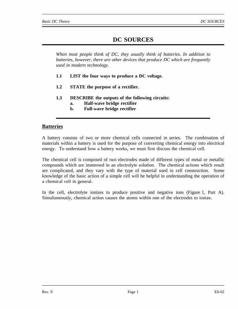
Basic DC Theory DC SOURCES
DC SOURCES
When most people think of DC, they usually think of batteries. In addition tobatteries, however, there are other devices that produce DC which are frequentlyused in modern technology.
1.1 LIST the four ways to produce a DC voltage.
1.2 STATE the purpose of a rectifier.
1.3 DESCRIBE the outputs of the following circuits:a. Half-wave bridge rectifierb. Full-wave bridge rectifier
Batteries
A battery consists of two or more chemical cells connected in series. The combination ofmaterials within a battery is used for the purpose of converting chemical energy into electricalenergy. To understand how a battery works, we must first discuss the chemical cell.
The chemical cell is composed of two electrodes made of different types of metal or metalliccompounds which are immersed in an electrolyte solution. The chemical actions which resultare complicated, and they vary with the type of material used in cell construction. Someknowledge of the basic action of a simple cell will be helpful in understanding the operation ofa chemical cell in general.
In the cell, electrolyte ionizes to produce positive and negative ions (Figure 1, Part A).Simultaneously, chemical action causes the atoms within one of the electrodes to ionize.
Rev. 0 Page 1 ES-02
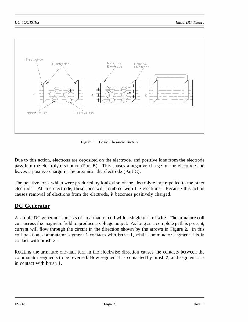
DC SOURCES Basic DC Theory
Figure 1 Basic Chemical Battery
Due to this action, electrons are deposited on the electrode, and positive ions from the electrodepass into the electrolyte solution (Part B). This causes a negative charge on the electrode andleaves a positive charge in the area near the electrode (Part C).
The positive ions, which were produced by ionization of the electrolyte, are repelled to the otherelectrode. At this electrode, these ions will combine with the electrons. Because this actioncauses removal of electrons from the electrode, it becomes positively charged.
DC Generator
A simple DC generator consists of an armature coil with a single turn of wire. The armature coilcuts across the magnetic field to produce a voltage output. As long as a complete path is present,current will flow through the circuit in the direction shown by the arrows in Figure 2. In thiscoil position, commutator segment 1 contacts with brush 1, while commutator segment 2 is incontact with brush 2.
Rotating the armature one-half turn in the clockwise direction causes the contacts between thecommutator segments to be reversed. Now segment 1 is contacted by brush 2, and segment 2 isin contact with brush 1.
ES-02 Page 2 Rev. 0
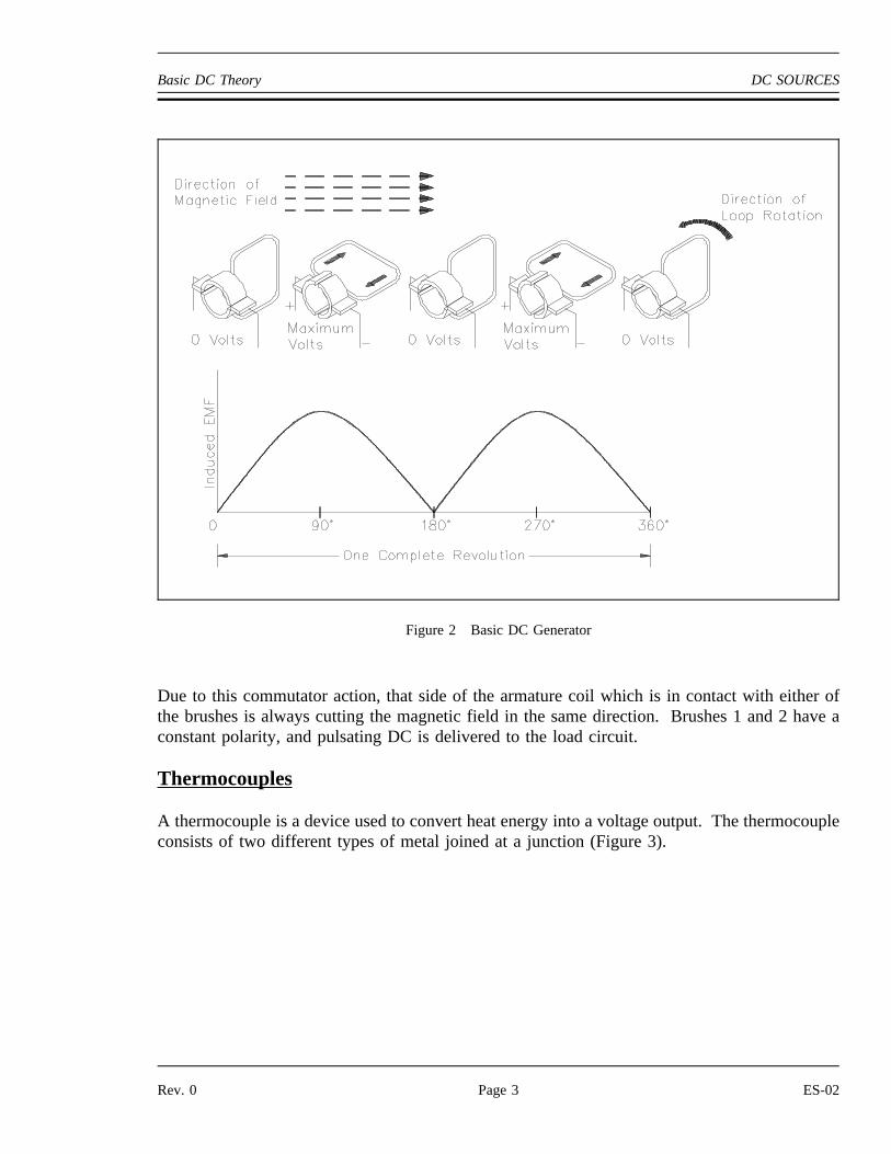
Basic DC Theory DC SOURCES
Figure 2 Basic DC Generator
Due to this commutator action, that side of the armature coil which is in contact with either ofthe brushes is always cutting the magnetic field in the same direction. Brushes 1 and 2 have aconstant polarity, and pulsating DC is delivered to the load circuit.
Thermocouples
A thermocouple is a device used to convert heat energy into a voltage output. The thermocoupleconsists of two different types of metal joined at a junction (Figure 3).
Rev. 0 Page 3 ES-02
DC SOURCES Basic DC Theory
Figure 3 Production of a DC Voltage Using a Thermocouple
ES-02 Page 4 Rev. 0
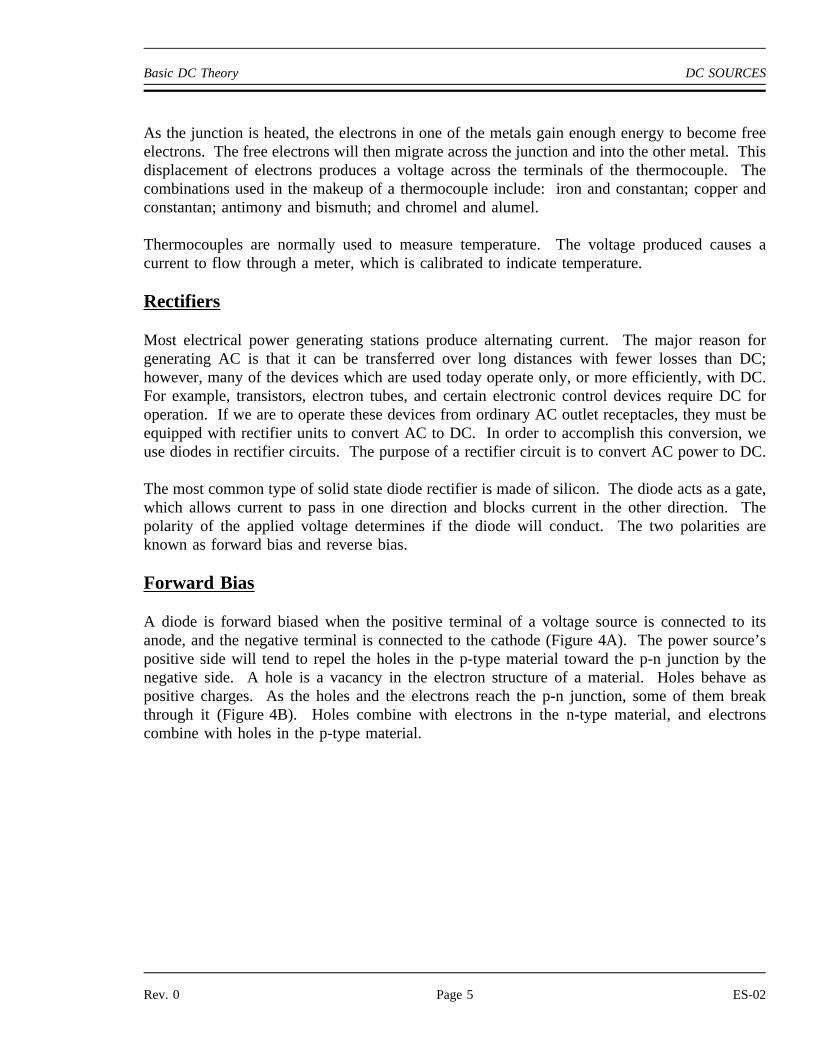
Basic DC Theory DC SOURCES
As the junction is heated, the electrons in one of the metals gain enough energy to become freeelectrons. The free electrons will then migrate across the junction and into the other metal. Thisdisplacement of electrons produces a voltage across the terminals of the thermocouple. Thecombinations used in the makeup of a thermocouple include: iron and constantan; copper andconstantan; antimony and bismuth; and chromel and alumel.
Thermocouples are normally used to measure temperature. The voltage produced causes acurrent to flow through a meter, which is calibrated to indicate temperature.
Rectifiers
Most electrical power generating stations produce alternating current. The major reason forgenerating AC is that it can be transferred over long distances with fewer losses than DC;however, many of the devices which are used today operate only, or more efficiently, with DC.For example, transistors, electron tubes, and certain electronic control devices require DC foroperation. If we are to operate these devices from ordinary AC outlet receptacles, they must beequipped with rectifier units to convert AC to DC. In order to accomplish this conversion, weuse diodes in rectifier circuits. The purpose of a rectifier circuit is to convert AC power to DC.
The most common type of solid state diode rectifier is made of silicon. The diode acts as a gate,which allows current to pass in one direction and blocks current in the other direction. Thepolarity of the applied voltage determines if the diode will conduct. The two polarities areknown as forward bias and reverse bias.
Forward Bias
A diode is forward biased when the positive terminal of a voltage source is connected to itsanode, and the negative terminal is connected to the cathode (Figure 4A). The power source’spositive side will tend to repel the holes in the p-type material toward the p-n junction by thenegative side. A hole is a vacancy in the electron structure of a material. Holes behave aspositive charges. As the holes and the electrons reach the p-n junction, some of them breakthrough it (Figure 4B). Holes combine with electrons in the n-type material, and electronscombine with holes in the p-type material.
Rev. 0 Page 5 ES-02
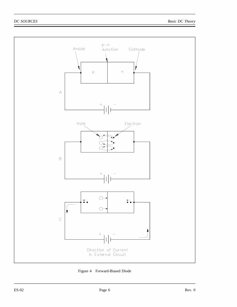
DC SOURCES Basic DC Theory
Figure 4 Forward-Biased Diode
ES-02 Page 6 Rev. 0
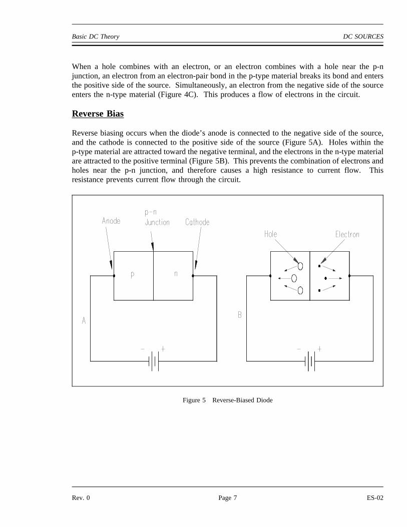
Basic DC Theory DC SOURCES
When a hole combines with an electron, or an electron combines with a hole near the p-njunction, an electron from an electron-pair bond in the p-type material breaks its bond and entersthe positive side of the source. Simultaneously, an electron from the negative side of the sourceenters the n-type material (Figure 4C). This produces a flow of electrons in the circuit.
Reverse Bias
Reverse biasing occurs when the diode’s anode is connected to the negative side of the source,and the cathode is connected to the positive side of the source (Figure 5A). Holes within thep-type material are attracted toward the negative terminal, and the electrons in the n-type materialare attracted to the positive terminal (Figure 5B). This prevents the combination of electrons andholes near the p-n junction, and therefore causes a high resistance to current flow. Thisresistance prevents current flow through the circuit.
Figure 5 Reverse-Biased Diode
Rev. 0 Page 7 ES-02
DC SOURCES Basic DC Theory
Half-Wave Rectifier Circuit
When a diode is connected to a source of alternating voltage, it will be alternatelyforward-biased, and then reverse-biased, during each cycle of the AC sine-wave. When a singlediode is used in a rectifier circuit, current will flow through the circuit only during one-half ofthe input voltage cycle (Figure 6). For this reason, this rectifier circuit is called a half-waverectifier. The output of a half-wave rectifier circuit is pulsating DC.
Figure 6 Half-Wave Rectifier
ES-02 Page 8 Rev. 0

Basic DC Theory DC SOURCES
Full-Wave Rectifier Circuit
A full-wave rectifier circuit is a circuit that rectifies the entire cycle of the AC sine-wave. Abasic full-wave rectifier uses two diodes. The action of these diodes during each half cycle isshown in Figure 7.
Figure 7 Full-Wave Rectifier
Rev. 0 Page 9 ES-02
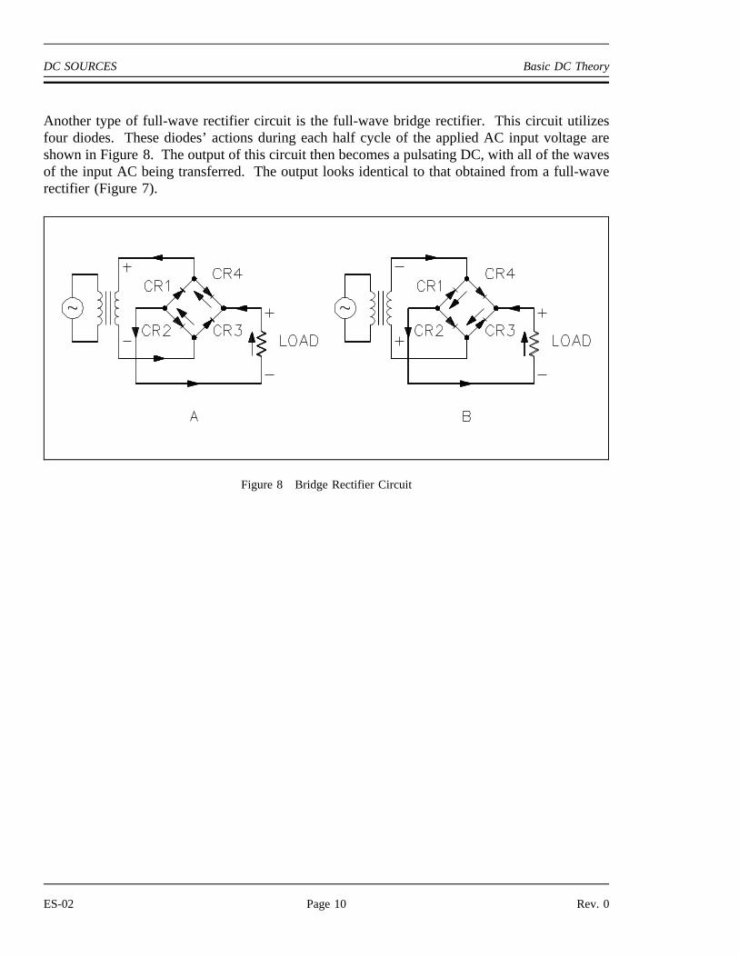
DC SOURCES Basic DC Theory
Another type of full-wave rectifier circuit is the full-wave bridge rectifier. This circuit utilizesfour diodes. These diodes’ actions during each half cycle of the applied AC input voltage areshown in Figure 8. The output of this circuit then becomes a pulsating DC, with all of the wavesof the input AC being transferred. The output looks identical to that obtained from a full-waverectifier (Figure 7).
Figure 8 Bridge Rectifier Circuit
ES-02 Page 10 Rev. 0
Basic DC Theory DC SOURCES
Summary
The important information concerning DC sources is summarized below.
DC Sources Summary
There are four common ways that DC voltages are produced.
- Batteries- DC Generators- Thermocouples- Rectifiers
Thermocouples convert energy from temperature into a DC voltage. Thisvoltage can be used to measure temperature.
A rectifier converts AC to DC.
There are two types of rectifiers.
- Half-Wave rectifiers- Full-Wave rectifiers
Half-wave rectifiers convert the AC to a pulsating DC and convert only one-half of the sine wave.
Full-wave rectifiers convert the AC to a pulsating DC and convert all of thesine wave.
Rev. 0 Page 11 ES-02
DC CIRCUIT TERMINOLOGY Basic DC Theory
DC CIRCUIT TERMINOLOGY
Before operations with DC circuits can be studied, an understanding of the typesof circuits and common circuit terminology associated with circuits is essential.
EO 1.4 Given a diagram, IDENTIFY it as one of the followingtypes:a. Schematic diagramb. One-line diagramc. Block diagramd. Wiring diagram
EO 1.5 DEFINE the following terms:a. Resistivityb. Temperature coefficient of resistancec. Closed circuitd. Open circuite. Short circuitf. Series circuitg. Parallel circuith. Equivalent resistance
EO 1.6 Given a circuit, DETERMINE whether the circuit is anopen circuit or a closed circuit.
Schematic Diagram
Schematic diagrams are the standard means by which we communicate information in electricaland electronics circuits. On schematic diagrams, the component parts are represented by graphicsymbols, some of which were presented earlier in Module 1. Because graphic symbols are small,it is possible to have diagrams in a compact form. The symbols and associated lines show howcircuit components are connected and the relationship of those components with one another.
As an example, let us look at a schematic diagram of a two-transistor radio circuit (Figure 9).This diagram, from left to right, shows the components in the order they are used to convertradio waves into sound energy. By using this diagram it is possible to trace the operation of thecircuit from beginning to end. Due to this important feature of schematic diagrams, they arewidely used in construction, maintenance, and servicing of all types of electronic circuits.
ES-02 Page 12 Rev. 0
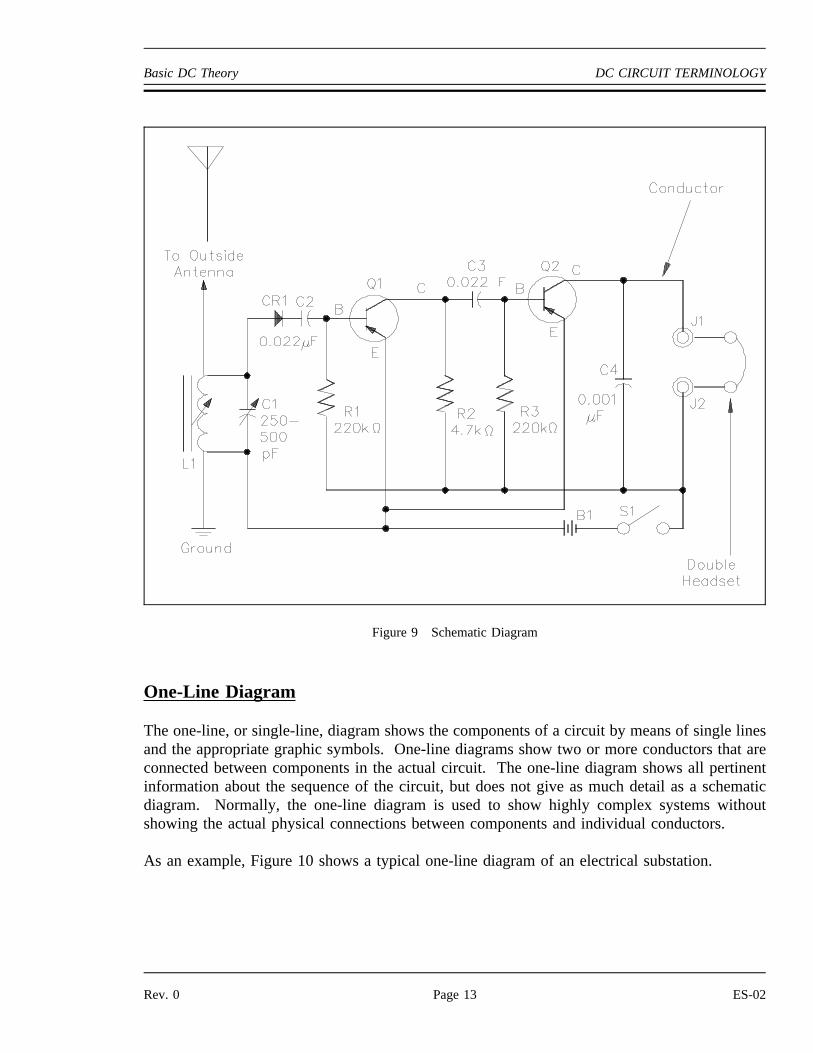
Basic DC Theory DC CIRCUIT TERMINOLOGY
Figure 9 Schematic Diagram
One-Line Diagram
The one-line, or single-line, diagram shows the components of a circuit by means of single linesand the appropriate graphic symbols. One-line diagrams show two or more conductors that areconnected between components in the actual circuit. The one-line diagram shows all pertinentinformation about the sequence of the circuit, but does not give as much detail as a schematicdiagram. Normally, the one-line diagram is used to show highly complex systems withoutshowing the actual physical connections between components and individual conductors.
As an example, Figure 10 shows a typical one-line diagram of an electrical substation.
Rev. 0 Page 13 ES-02
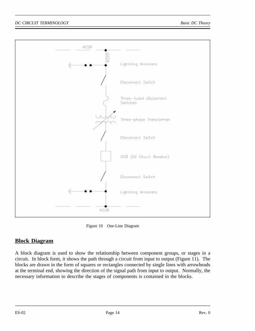
DC CIRCUIT TERMINOLOGY Basic DC Theory
Block Diagram
Figure 10 One-Line Diagram
A block diagram is used to show the relationship between component groups, or stages in acircuit. In block form, it shows the path through a circuit from input to output (Figure 11). Theblocks are drawn in the form of squares or rectangles connected by single lines with arrowheadsat the terminal end, showing the direction of the signal path from input to output. Normally, thenecessary information to describe the stages of components is contained in the blocks.
ES-02 Page 14 Rev. 0
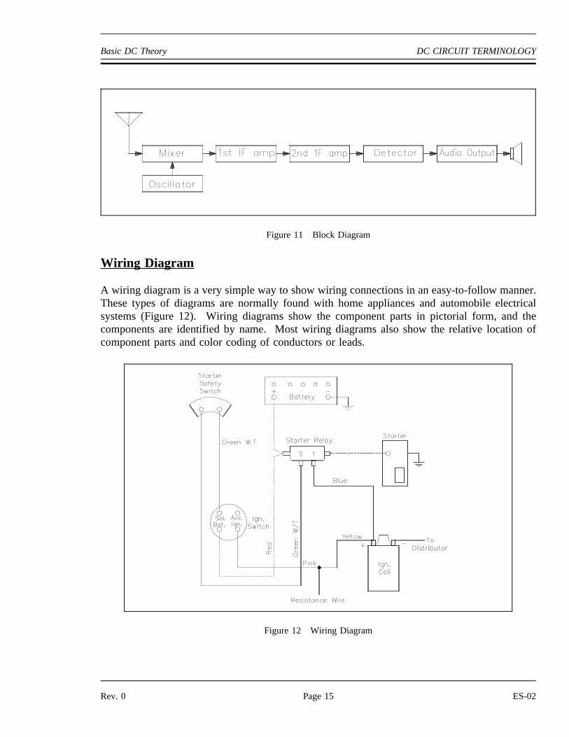
Basic DC Theory DC CIRCUIT TERMINOLOGY
Wiring Diagram
Figure 11 Block Diagram
A wiring diagram is a very simple way to show wiring connections in an easy-to-follow manner.These types of diagrams are normally found with home appliances and automobile electricalsystems (Figure 12). Wiring diagrams show the component parts in pictorial form, and thecomponents are identified by name. Most wiring diagrams also show the relative location ofcomponent parts and color coding of conductors or leads.
Figure 12 Wiring Diagram
Rev. 0 Page 15 ES-02
DC CIRCUIT TERMINOLOGY Basic DC Theory
Resistivity
Resistivityis defined as the measure of the resistance a material imposes on current flow. Theresistance of a given length of conductor depends upon the resistivity of that material, the lengthof the conductor, and the cross-sectional area of the conductor, according to Equation (2-1).
R = (2-1)ρ LA
where
R = resistance of conductor,Ω
ρ = specific resistance or resistivity cm-Ω/ft
L = length of conductor, ft
A = cross-sectional area of conductor, cm
The resistivityρ (rho) allows different materials to be compared for resistance, according to theirnature, without regard to length or area. The higher the value ofρ, the higher the resistance.
Table 1 gives resistivity values for metals having the standard wire size of one foot in length anda cross-sectional area of 1 cm.
ES-02 Page 16 Rev. 0
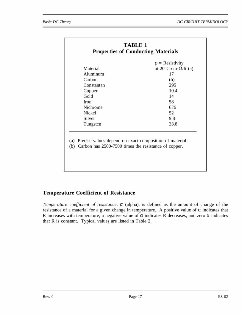
Basic DC Theory DC CIRCUIT TERMINOLOGY
TABLE 1Properties of Conducting Materials
ρ = ResistivityMaterial at 20°C-cm-Ω/ft (a)Aluminum 17Carbon (b)Constantan 295Copper 10.4Gold 14Iron 58Nichrome 676Nickel 52Silver 9.8Tungsten 33.8
(a) Precise values depend on exact composition of material.(b) Carbon has 2500-7500 times the resistance of copper.
Temperature Coefficient of Resistance
Temperature coefficient of resistance, α (alpha), is defined as the amount of change of theresistance of a material for a given change in temperature. A positive value ofα indicates thatR increases with temperature; a negative value ofα indicates R decreases; and zeroα indicatesthat R is constant. Typical values are listed in Table 2.
Rev. 0 Page 17 ES-02
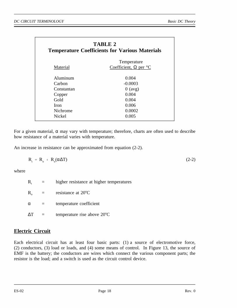
DC CIRCUIT TERMINOLOGY Basic DC Theory
TABLE 2Temperature Coefficients for Various Materials
TemperatureMaterial Coefficient,Ω per °C
Aluminum 0.004Carbon -0.0003Constantan 0 (avg)Copper 0.004Gold 0.004Iron 0.006Nichrome 0.0002Nickel 0.005
For a given material,α may vary with temperature; therefore, charts are often used to describehow resistance of a material varies with temperature.
An increase in resistance can be approximated from equation (2-2).
(2-2)Rt Ro Ro(α∆T)
where
Rt = higher resistance at higher temperatures
Ro = resistance at 20oC
α = temperature coefficient
∆T = temperature rise above 20oC
Electric Circuit
Each electrical circuit has at least four basic parts: (1) a source of electromotive force,(2) conductors, (3) load or loads, and (4) some means of control. In Figure 13, the source ofEMF is the battery; the conductors are wires which connect the various component parts; theresistor is the load; and a switch is used as the circuit control device.
ES-02 Page 18 Rev. 0
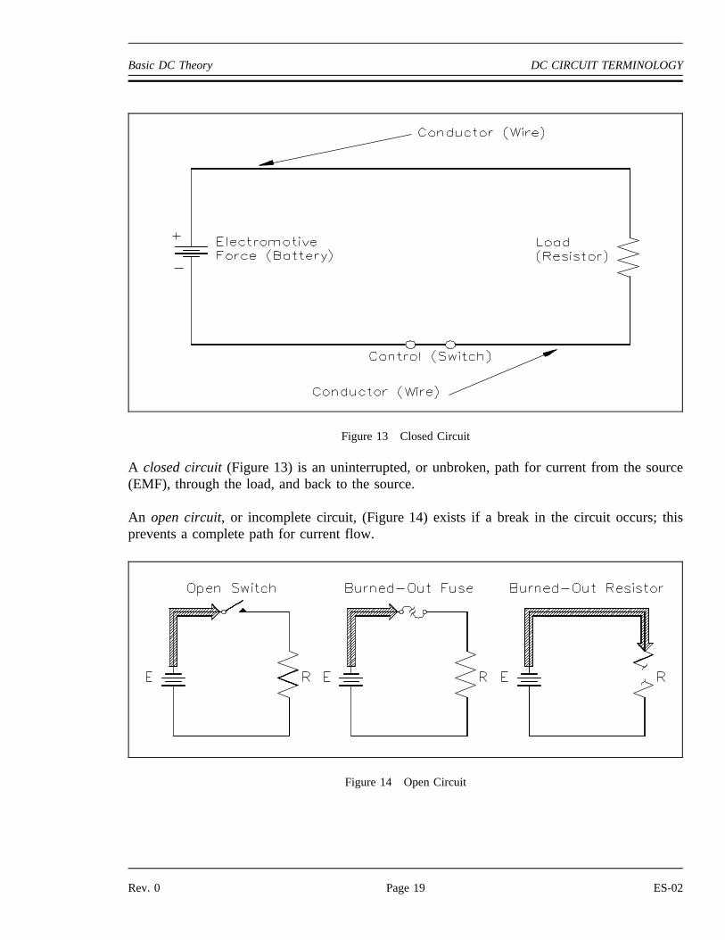
Basic DC Theory DC CIRCUIT TERMINOLOGY
A closed circuit(Figure 13) is an uninterrupted, or unbroken, path for current from the source
Figure 13 Closed Circuit
(EMF), through the load, and back to the source.
An open circuit, or incomplete circuit, (Figure 14) exists if a break in the circuit occurs; thisprevents a complete path for current flow.
Figure 14 Open Circuit
Rev. 0 Page 19 ES-02
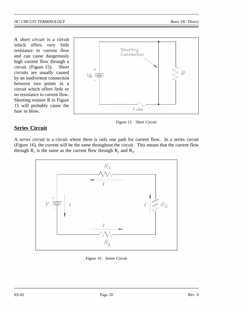
DC CIRCUIT TERMINOLOGY Basic DC Theory
A short circuit is a circuit
Figure 15 Short Circuit
which offers very littleresistance to current flowand can cause dangerouslyhigh current flow through acircuit (Figure 15). Shortcircuits are usually causedby an inadvertent connectionbetween two points in acircuit which offers little orno resistance to current flow.Shorting resistor R in Figure15 will probably cause thefuse to blow.
Series Circuit
A series circuitis a circuit where there is only one path for current flow. In a series circuit(Figure 16), the current will be the same throughout the circuit. This means that the current flowthrough R1 is the same as the current flow through R2 and R3.
Figure 16 Series Circuit
ES-02 Page 20 Rev. 0
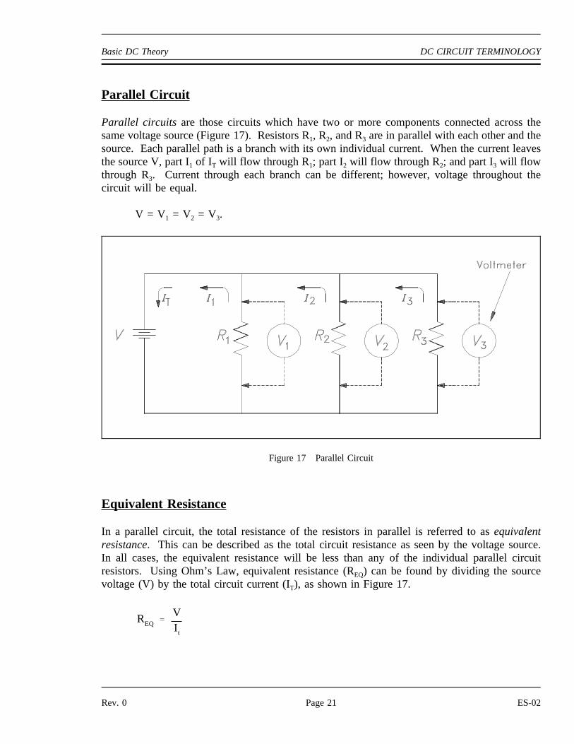
Basic DC Theory DC CIRCUIT TERMINOLOGY
Parallel Circuit
Parallel circuits are those circuits which have two or more components connected across thesame voltage source (Figure 17). Resistors R1, R2, and R3 are in parallel with each other and thesource. Each parallel path is a branch with its own individual current. When the current leavesthe source V, part I1 of IT will flow through R1; part I2 will flow through R2; and part I3 will flowthrough R3. Current through each branch can be different; however, voltage throughout thecircuit will be equal.
V = V1 = V2 = V3.
Figure 17 Parallel Circuit
Equivalent Resistance
In a parallel circuit, the total resistance of the resistors in parallel is referred to asequivalentresistance. This can be described as the total circuit resistance as seen by the voltage source.In all cases, the equivalent resistance will be less than any of the individual parallel circuitresistors. Using Ohm’s Law, equivalent resistance (REQ) can be found by dividing the sourcevoltage (V) by the total circuit current (IT), as shown in Figure 17.
REQ
VIt
Rev. 0 Page 21 ES-02
DC CIRCUIT TERMINOLOGY Basic DC Theory
Summary
The important information concerning basic DC circuits is summarized below.
DC Circuit Terminology Summary
There are four types of circuit diagrams.
- Schematic diagram- One-line diagram- Block diagram- Wiring diagram
Resistivity is defined as the measure of the resistance a material imposes oncurrent flow.
Temperature coefficient of resistance,α (alpha), is defined as the amount ofchange of the resistance of a material for a given change in temperature.
A closed circuit is one that has a complete path for current flow.
An open circuit is one that does not have a complete path for current flow.
A short circuit is a circuit with a path that has little or no resistance to currentflow.
A series circuit is one where there is only one path for current flow.
A parallel circuit is one which has two or more components connected acrossthe same voltage source.
Equivalent resistance is the total resistance of the resistors in parallel.
ES-02 Page 22 Rev. 0
Basic DC Theory BASIC DC CIRCUIT CALCULATIONS
BASIC DC CIRCUIT CALCULATIONS
Each type of DC circuit contains certain characteristics that determine the wayits voltage and current behave. To begin analysis of the voltages and currents ateach part of a circuit, an understanding of these characteristics is necessary.
EO 1.7 Given a circuit, CALCULATE total resistance for aseries or parallel circuit.
EO 1.8 DESCRIBE what is meant by the term "voltagedivider."
EO 1.9 DESCRIBE what is meant by the term "currentdivision."
Series Resistance
The total resistance in a series circuit is equal to the sum of all the parts of that circuit, as shownin equation (2-3).
RT = R1 + R2 + R3 ... etc. (2-3)
where
RT = resistance total
R1, R2, and R3 = resistance in series
Example: A series circuit has a 60Ω, a 100Ω, and a 150Ω resistor in series (Figure 18).What is the total resistance of the circuit?
Solution:
RT = R1 + R2 + R3
= 60 + 100 + 150= 310 Ω
Rev. 0 Page 23 ES-02
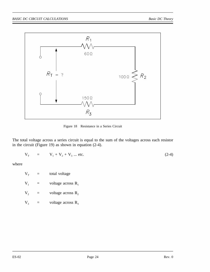
BASIC DC CIRCUIT CALCULATIONS Basic DC Theory
Figure 18 Resistance in a Series Circuit
The total voltage across a series circuit is equal to the sum of the voltages across each resistorin the circuit (Figure 19) as shown in equation (2-4).
VT = V1 + V2 + V3 ... etc. (2-4)
where
VT = total voltage
V1 = voltage across R1
V2 = voltage across R2
V3 = voltage across R3
ES-02 Page 24 Rev. 0
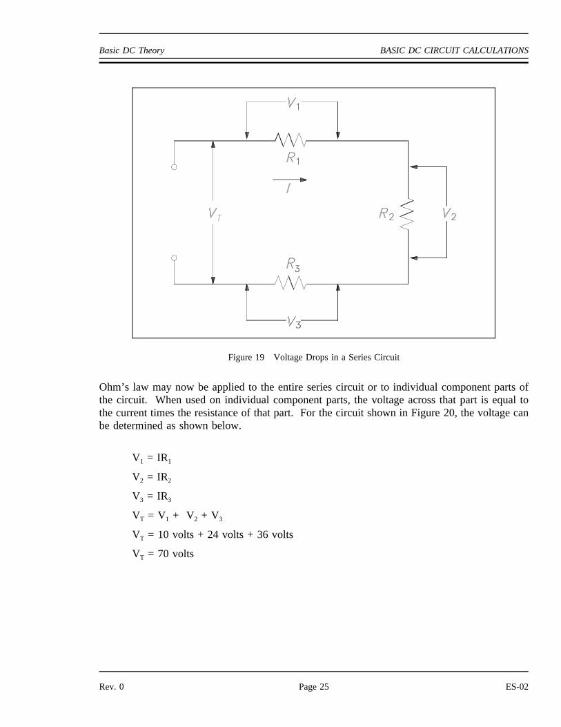
Basic DC Theory BASIC DC CIRCUIT CALCULATIONS
Figure 19 Voltage Drops in a Series Circuit
Ohm’s law may now be applied to the entire series circuit or to individual component parts ofthe circuit. When used on individual component parts, the voltage across that part is equal tothe current times the resistance of that part. For the circuit shown in Figure 20, the voltage canbe determined as shown below.
V1 = IR1
V2 = IR2
V3 = IR3
VT = V1 + V2 + V3
VT = 10 volts + 24 volts + 36 volts
VT = 70 volts
Rev. 0 Page 25 ES-02
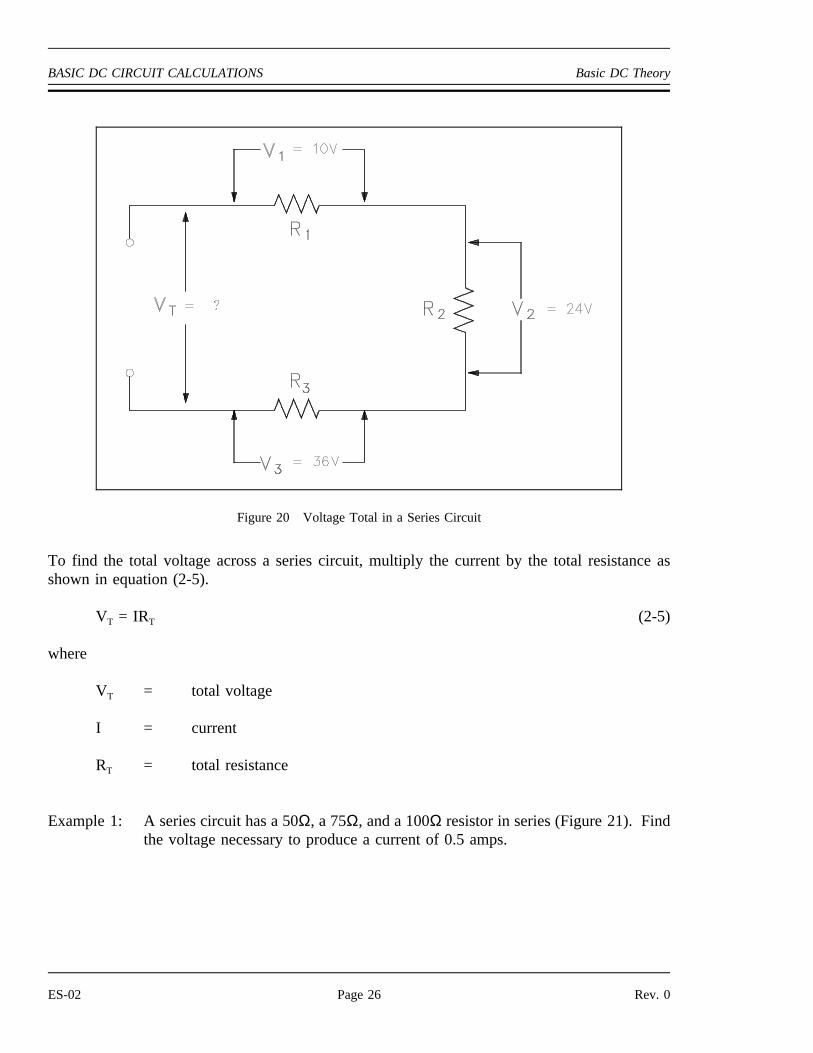
BASIC DC CIRCUIT CALCULATIONS Basic DC Theory
Figure 20 Voltage Total in a Series Circuit
To find the total voltage across a series circuit, multiply the current by the total resistance asshown in equation (2-5).
VT = IRT (2-5)
where
VT = total voltage
I = current
RT = total resistance
Example 1: A series circuit has a 50Ω, a 75Ω, and a 100Ω resistor in series (Figure 21). Findthe voltage necessary to produce a current of 0.5 amps.
ES-02 Page 26 Rev. 0
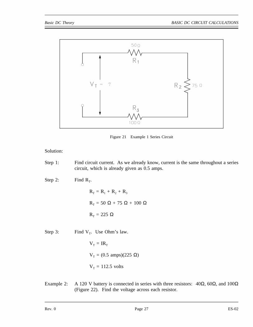
Basic DC Theory BASIC DC CIRCUIT CALCULATIONS
Figure 21 Example 1 Series Circuit
Solution:
Step 1: Find circuit current. As we already know, current is the same throughout a seriescircuit, which is already given as 0.5 amps.
Step 2: Find RT.
RT = R1 + R2 + R3
RT = 50 Ω + 75 Ω + 100 Ω
RT = 225 Ω
Step 3: Find VT. Use Ohm’s law.
VT = IRT
VT = (0.5 amps)(225Ω)
VT = 112.5 volts
Example 2: A 120 V battery is connected in series with three resistors: 40Ω, 60Ω, and 100Ω(Figure 22). Find the voltage across each resistor.
Rev. 0 Page 27 ES-02
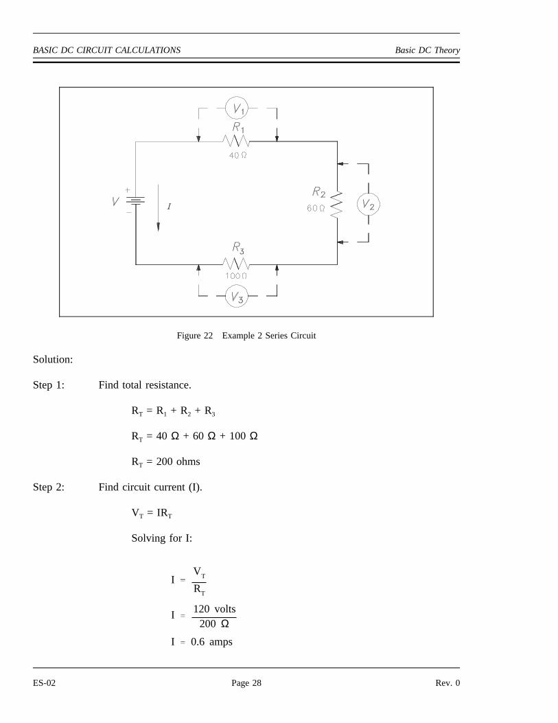
BASIC DC CIRCUIT CALCULATIONS Basic DC Theory
Figure 22 Example 2 Series Circuit
Solution:
Step 1: Find total resistance.
RT = R1 + R2 + R3
RT = 40 Ω + 60 Ω + 100 Ω
RT = 200 ohms
Step 2: Find circuit current (I).
VT = IRT
Solving for I:
IVT
RT
I 120 volts200 Ω
I 0.6 amps
ES-02 Page 28 Rev. 0
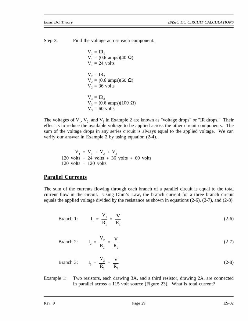
Basic DC Theory BASIC DC CIRCUIT CALCULATIONS
Step 3: Find the voltage across each component.
V1 = IR1
V1 = (0.6 amps)(40Ω)V1 = 24 volts
V2 = IR2
V2 = (0.6 amps)(60Ω)V2 = 36 volts
V3 = IR3
V3 = (0.6 amps)(100Ω)V3 = 60 volts
The voltages of V1, V2, and V3 in Example 2 are known as "voltage drops" or "IR drops." Theireffect is to reduce the available voltage to be applied across the other circuit components. Thesum of the voltage drops in any series circuit is always equal to the applied voltage. We canverify our answer in Example 2 by using equation (2-4).
VT V1 V2 V3
120 volts 24 volts 36 volts 60 volts120 volts 120 volts
Parallel Currents
The sum of the currents flowing through each branch of a parallel circuit is equal to the totalcurrent flow in the circuit. Using Ohm’s Law, the branch current for a three branch circuitequals the applied voltage divided by the resistance as shown in equations (2-6), (2-7), and (2-8).
Branch 1: (2-6)I1
V1
R1
VR1
Branch 2: (2-7)I2
V2
R2
VR2
Branch 3: (2-8)I3
V2
R2
VR2
Example 1: Two resistors, each drawing 3A, and a third resistor, drawing 2A, are connectedin parallel across a 115 volt source (Figure 23). What is total current?
Rev. 0 Page 29 ES-02
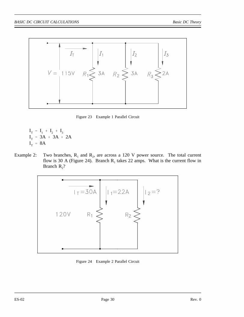
BASIC DC CIRCUIT CALCULATIONS Basic DC Theory
Figure 23 Example 1 Parallel Circuit
IT I1 I2 I3
IT 3A 3A 2AIT 8A
Example 2: Two branches, R1 and R2, are across a 120 V power source. The total currentflow is 30 A (Figure 24). Branch R1 takes 22 amps. What is the current flow inBranch R2?
Figure 24 Example 2 Parallel Circuit
ES-02 Page 30 Rev. 0
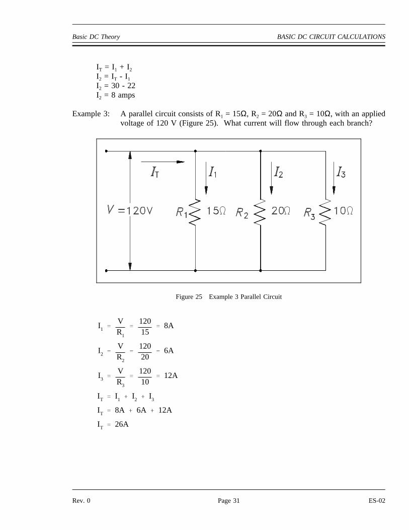
Basic DC Theory BASIC DC CIRCUIT CALCULATIONS
IT = I1 + I2
I2 = IT - I1
I2 = 30 - 22I2 = 8 amps
Example 3: A parallel circuit consists of R1 = 15Ω, R2 = 20Ω and R3 = 10Ω, with an appliedvoltage of 120 V (Figure 25). What current will flow through each branch?
Figure 25 Example 3 Parallel Circuit
I1
VR1
12015
8A
I2
VR2
12020
6A
I3
VR3
12010
12A
IT I1 I2 I3
IT 8A 6A 12A
IT 26A
Rev. 0 Page 31 ES-02
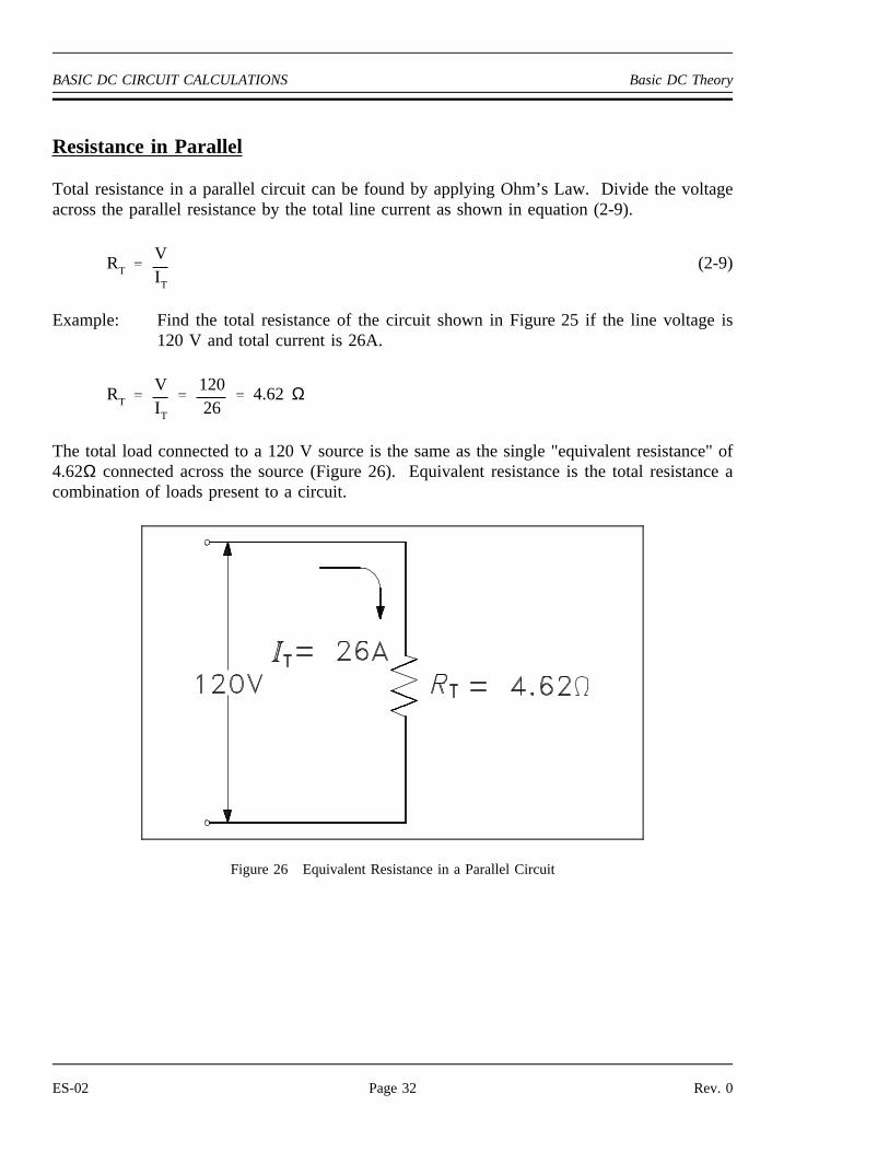
BASIC DC CIRCUIT CALCULATIONS Basic DC Theory
Resistance in Parallel
Total resistance in a parallel circuit can be found by applying Ohm’s Law. Divide the voltageacross the parallel resistance by the total line current as shown in equation (2-9).
(2-9)RT
VIT
Example: Find the total resistance of the circuit shown in Figure 25 if the line voltage is120 V and total current is 26A.
RT
VIT
12026
4.62 Ω
The total load connected to a 120 V source is the same as the single "equivalent resistance" of4.62Ω connected across the source (Figure 26). Equivalent resistance is the total resistance acombination of loads present to a circuit.
Figure 26 Equivalent Resistance in a Parallel Circuit
ES-02 Page 32 Rev. 0
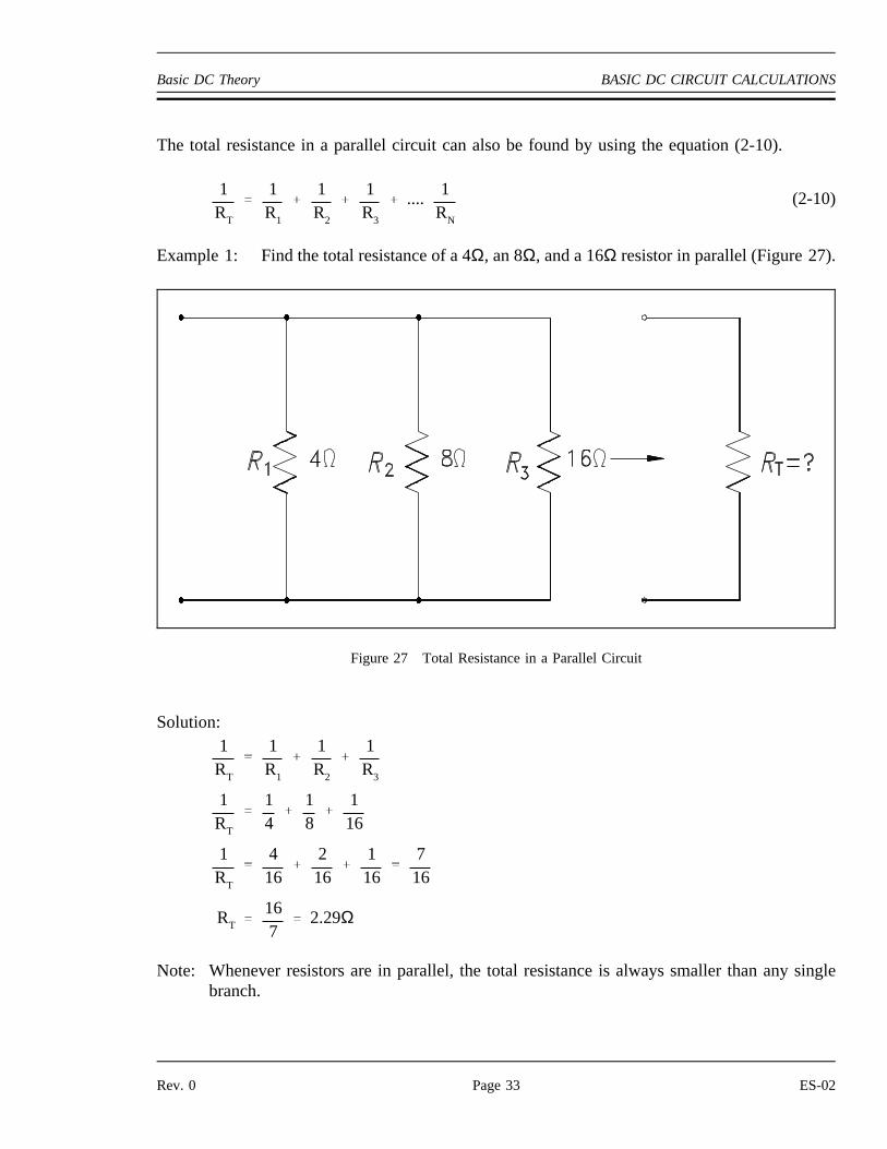
Basic DC Theory BASIC DC CIRCUIT CALCULATIONS
The total resistance in a parallel circuit can also be found by using the equation (2-10).
(2-10)1RT
1R1
1R2
1R3
.... 1RN
Example 1: Find the total resistance of a 4Ω, an 8Ω, and a 16Ω resistor in parallel (Figure 27).
Figure 27 Total Resistance in a Parallel Circuit
Solution:1RT
1R1
1R2
1R3
1RT
14
18
116
1RT
416
216
116
716
RT
167
2.29Ω
Note: Whenever resistors are in parallel, the total resistance is always smaller than any singlebranch.
Rev. 0 Page 33 ES-02
BASIC DC CIRCUIT CALCULATIONS Basic DC Theory
Example 2: Now add a fourth resistance of 4Ω in parallel to the circuit in Figure 27. Whatis the new total resistance of the circuit?
Solution:
1RT
1R1
1R2
1R3
1R4
1RT
14
18
116
14
1RT
416
216
116
416
1116
RT
1611
1.45Ω
Simplified Formulas
Total resistance of equal resistors in a parallel circuit is equal to the resistance of one resistordivided by the number of resistors.
RT
RN
where
RT = total resistance
R = resistance of one resistor
N = number of resistors
Example: Five lamps, each with a resistance of 40Ω, are connected in parallel. Find totalresistance.
R R1 R2 R3 R4 R5 40Ω
N 5
RT
RN
405
8Ω
ES-02 Page 34 Rev. 0
Basic DC Theory BASIC DC CIRCUIT CALCULATIONS
When any two resistors are unequal in a parallel circuit, it is easier to calculate RT by multiplyingthe two resistances and then dividing the product by the sum, as shown in equation (2-11). Asshown in equation (2-11), this is valid when there are only two resistors in parallel.
(2-11)RT
R1R2
R1 R2
Example: Find the total resistance of a parallel circuit which has one 12Ω and one 4Ωresistor.
RT
R1R2
R1 R2
(12)(4)12 4
4816
3Ω
In certain cases involving two resistors in parallel, it is useful to find an unknown resistor, Rx,to obtain a certain RT. To find the appropriate formula, we start with equation (2-10) and let theknown resistor be R and the unknown resistor be Rx.
RT
RRX
R RX
Cross multiply: RTR + RTRX = RRX
Transpose: RRX - RTRX = RTR
Factor: RX (R - RT) = RTR
Solve for Rx: RX
RTR
R RT
Rev. 0 Page 35 ES-02
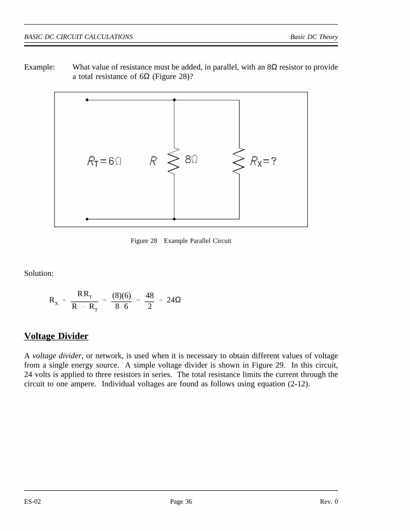
BASIC DC CIRCUIT CALCULATIONS Basic DC Theory
Example: What value of resistance must be added, in parallel, with an 8Ω resistor to providea total resistance of 6Ω (Figure 28)?
Figure 28 Example Parallel Circuit
Solution:
RX
RRT
R RT
(8)(6)8 6
482
24Ω
Voltage Divider
A voltage divider, or network, is used when it is necessary to obtain different values of voltagefrom a single energy source. A simple voltage divider is shown in Figure 29. In this circuit,24 volts is applied to three resistors in series. The total resistance limits the current through thecircuit to one ampere. Individual voltages are found as follows using equation (2-12).
ES-02 Page 36 Rev. 0
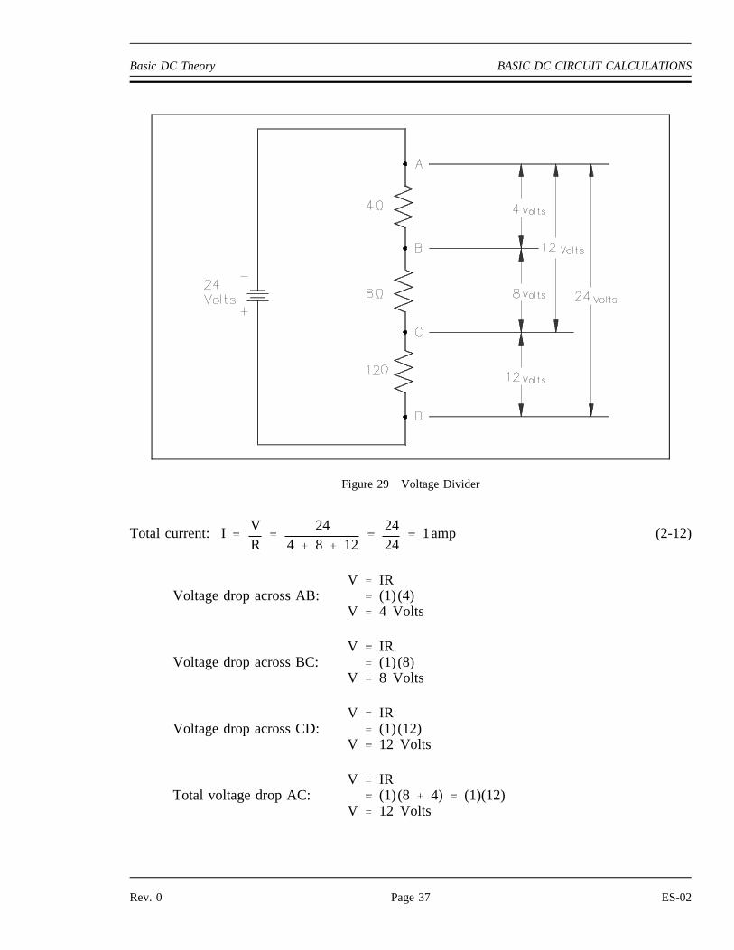
Basic DC Theory BASIC DC CIRCUIT CALCULATIONS
Total current: (2-12)
Figure 29 Voltage Divider
I VR
244 8 12
2424
1amp
Voltage drop across AB:V IR
(1)(4)V 4 Volts
Voltage drop across BC:V IR
(1)(8)V 8 Volts
Voltage drop across CD:V IR
(1)(12)V 12 Volts
Total voltage drop AC:V IR
(1)(8 4) (1)(12)V 12 Volts
Rev. 0 Page 37 ES-02
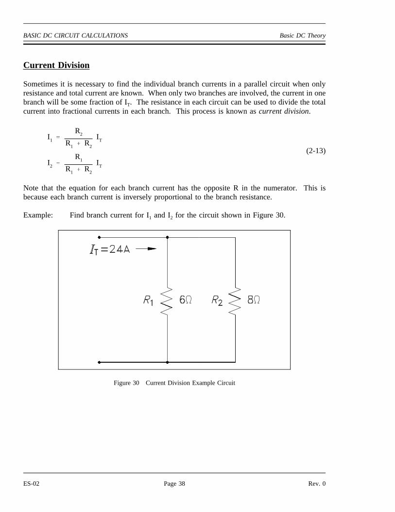
BASIC DC CIRCUIT CALCULATIONS Basic DC Theory
Current Division
Sometimes it is necessary to find the individual branch currents in a parallel circuit when onlyresistance and total current are known. When only two branches are involved, the current in onebranch will be some fraction of IT. The resistance in each circuit can be used to divide the totalcurrent into fractional currents in each branch. This process is known ascurrent division.
(2-13)
I1
R2
R1 R2
IT
I2
R1
R1 R2
IT
Note that the equation for each branch current has the opposite R in the numerator. This isbecause each branch current is inversely proportional to the branch resistance.
Example: Find branch current for I1 and I2 for the circuit shown in Figure 30.
Figure 30 Current Division Example Circuit
ES-02 Page 38 Rev. 0
Basic DC Theory BASIC DC CIRCUIT CALCULATIONS
Solution:
I1
R2
R1 R2
IT
86 8
(24) 814
(24) 13.71 amps
I2
R1
R1 R2
IT
66 8
(24) 614
(24) 10.29 amps
Since I1 and IT were known, we could have also simply subtracted I1 from IT to find I2:
IT I1 I2
I2 IT I1
24 13.7110.29 amps
Summary
The important information in this chapter is summarized below.
Basic DC Circuit Calculations Summary
Equivalent resistance is a term used to represent the total resistance acombination of loads presents to a circuit.
A voltage divider is used to obtain different values of voltage from a singleenergy source.
Current division is used to determine the current flowing through each leg ofa parallel circuit.
Rev. 0 Page 39 ES-02
VOLTAGE POLARITY AND CURRENT DIRECTION Basic DC Theory
VOLTAGE POLARITY AND CURRENT DIRECTION
Before introducing the laws associated with complex DC circuit analysis, theimportance of voltage polarity and current direction must be understood. Thischapter will introduce the polarities and current direction associated with DCcircuits.
EO 1.10 DESCRIBE the difference between electron flow andconventional current flow.
EO 1.11 Given a circuit showing current flows, IDENTIFY thepolarity of the voltage drops in the circuit.
Conventional and Electron Flow
The direction of electron flow is from a point of negative potential to a point of positivepotential. The direction of positive charges, or holes, is in the opposite direction of electronflow. This flow of positive charges is known asconventional flow. All of the electrical effectsof electron flow from negative to positive, or from a high potential to a lower potential, are thesame as those that would be created by flow of positive charges in the opposite direction;therefore, it is important to realize that both conventions are in use, and they are essentiallyequivalent. In this manual, the electron flow convention is used.
Polarities
All voltages and currents have polarity as well as magnitude. In a series circuit, there is onlyone current, and its polarity is from the negative battery terminal through the rest of the circuitto the positive battery terminal. Voltage drops across loads also have polarities. The easiest wayto find these polarities is to use the direction of the electron current as a basis. Then, where theelectron current enters the load, the voltage is negative (Figure 31). This holds true regardlessof the number or type of loads in the circuit. The drop across the load is opposite to that of thesource. The voltage drops oppose the source voltage and reduce it for the other loads. This isbecause each load uses energy, leaving less energy for other loads.
ES-02 Page 40 Rev. 0
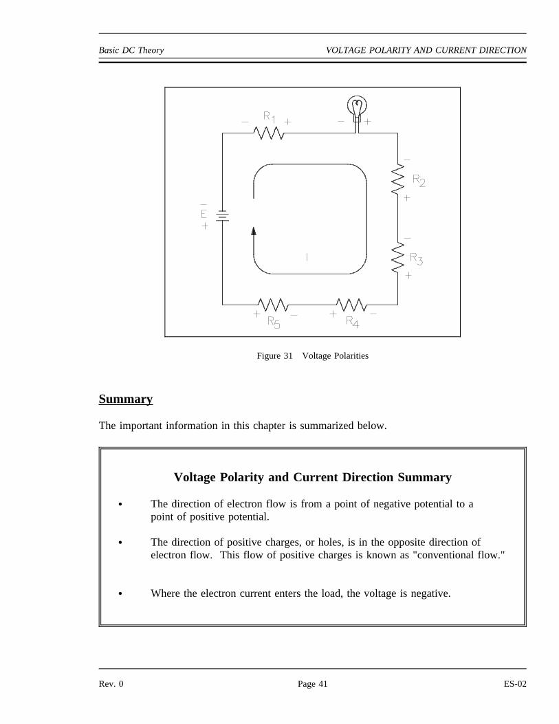
Basic DC Theory VOLTAGE POLARITY AND CURRENT DIRECTION
Figure 31 Voltage Polarities
Summary
The important information in this chapter is summarized below.
Voltage Polarity and Current Direction Summary
The direction of electron flow is from a point of negative potential to apoint of positive potential.
The direction of positive charges, or holes, is in the opposite direction ofelectron flow. This flow of positive charges is known as "conventional flow."
Where the electron current enters the load, the voltage is negative.
Rev. 0 Page 41 ES-02
KIRCHHOFF’S LAWS Basic DC Theory
KIRCHHOFF’S LAWS
Kirchhoff’s two laws reveal a unique relationship between current, voltage, andresistance in electrical circuits that is vital to performing and understandingelectrical circuit analysis.
EO 1.12 STATE Kirchhoff’s voltage law.
EO 1.13 STATE Kirchhoff’s current law.
EO 1.14 Given a circuit, SOLVE problems for voltage andcurrent using Kirchhoff’s laws.
Kirchhoff’s Laws
In all of the circuits examined so far, Ohm’s Law described the relationship between current,voltage, and resistance. These circuits have been relatively simple in nature. Many circuits areextremely complex and cannot be solved with Ohm’s Law. These circuits have many powersources and branches which would make the use of Ohm’s Law impractical or impossible.
Through experimentation in 1857 the German physicist Gustav Kirchhoff developed methods tosolve complex circuits. Kirchhoff developed two conclusions, known today as Kirchhoff’s Laws.
Law 1: The sum of the voltage drops around a closed loop is equal to the sum of thevoltage sources of that loop (Kirchhoff’s Voltage Law).
Law 2: The current arriving at any junction point in a circuit is equal to the currentleaving that junction (Kirchhoff’s Current Law).
Kirchhoff’s two laws may seem obvious based on what we already know about circuit theory.Even though they may seem very simple, they are powerful tools in solving complex and difficultcircuits.
Kirchhoff’s laws can be related to conservation of energy and charge if we look at a circuit withone load and source. Since all of the power provided from the source is consumed by the load,energy and charge are conserved. Since voltage and current can be related to energy and charge,then Kirchhoff’s laws are only restating the laws governing energy and charge conservation.
ES-02 Page 42 Rev. 0
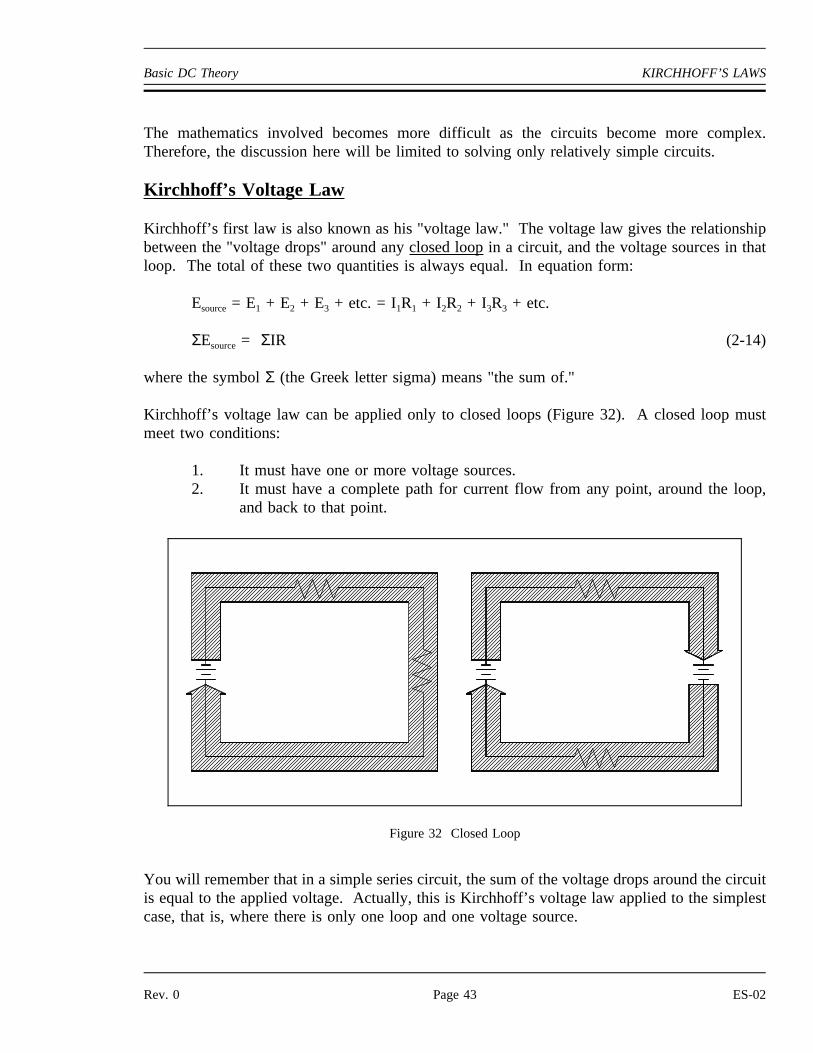
Basic DC Theory KIRCHHOFF’S LAWS
The mathematics involved becomes more difficult as the circuits become more complex.Therefore, the discussion here will be limited to solving only relatively simple circuits.
Kirchhoff’s Voltage Law
Kirchhoff’s first law is also known as his "voltage law." The voltage law gives the relationshipbetween the "voltage drops" around any closed loopin a circuit, and the voltage sources in thatloop. The total of these two quantities is always equal. In equation form:
Esource= E1 + E2 + E3 + etc. = I1R1 + I2R2 + I3R3 + etc.
ΣEsource= ΣIR (2-14)
where the symbolΣ (the Greek letter sigma) means "the sum of."
Kirchhoff’s voltage law can be applied only to closed loops (Figure 32). A closed loop mustmeet two conditions:
1. It must have one or more voltage sources.2. It must have a complete path for current flow from any point, around the loop,
and back to that point.
You will remember that in a simple series circuit, the sum of the voltage drops around the circuit
Figure 32 Closed Loop
is equal to the applied voltage. Actually, this is Kirchhoff’s voltage law applied to the simplestcase, that is, where there is only one loop and one voltage source.
Rev. 0 Page 43 ES-02
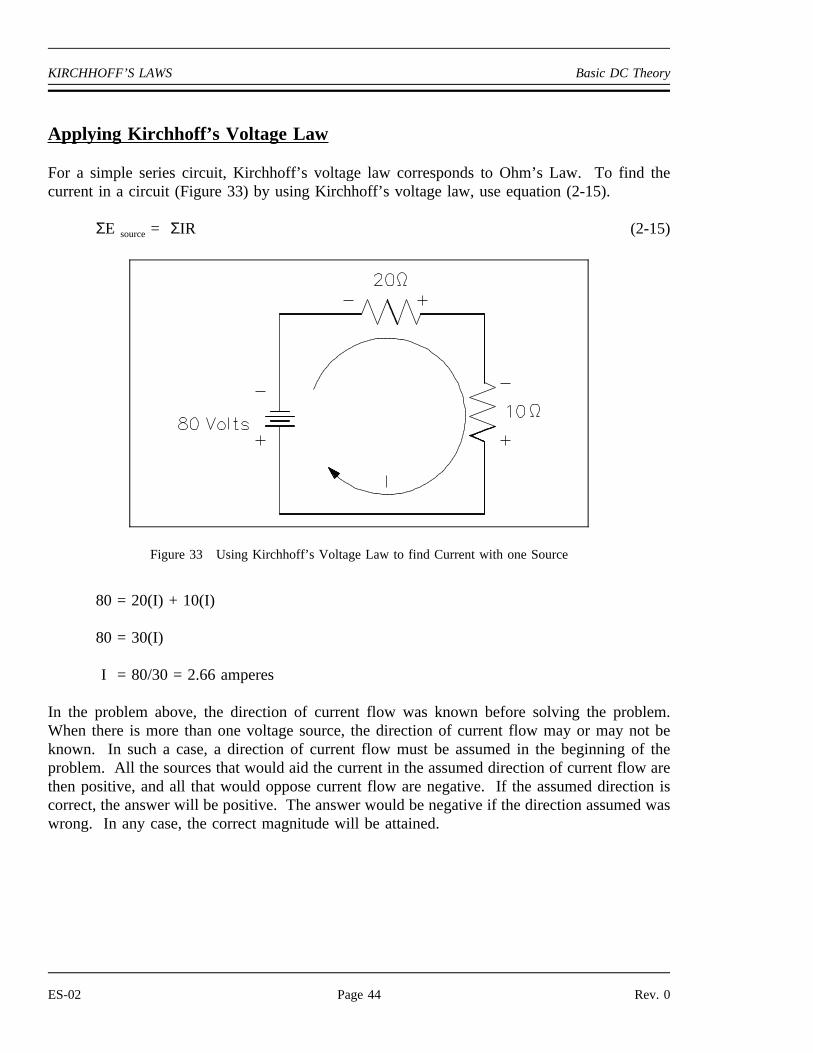
KIRCHHOFF’S LAWS Basic DC Theory
Applying Kirchhoff’s Voltage Law
For a simple series circuit, Kirchhoff’s voltage law corresponds to Ohm’s Law. To find thecurrent in a circuit (Figure 33) by using Kirchhoff’s voltage law, use equation (2-15).
ΣE source= ΣIR (2-15)
Figure 33 Using Kirchhoff’s Voltage Law to find Current with one Source
80 = 20(I) + 10(I)
80 = 30(I)
I = 80/30 = 2.66 amperes
In the problem above, the direction of current flow was known before solving the problem.When there is more than one voltage source, the direction of current flow may or may not beknown. In such a case, a direction of current flow must be assumed in the beginning of theproblem. All the sources that would aid the current in the assumed direction of current flow arethen positive, and all that would oppose current flow are negative. If the assumed direction iscorrect, the answer will be positive. The answer would be negative if the direction assumed waswrong. In any case, the correct magnitude will be attained.
ES-02 Page 44 Rev. 0
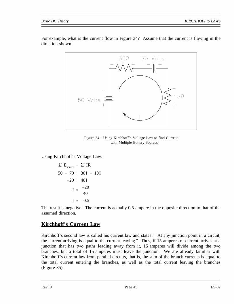
Basic DC Theory KIRCHHOFF’S LAWS
For example, what is the current flow in Figure 34? Assume that the current is flowing in thedirection shown.
Figure 34 Using Kirchhoff’s Voltage Law to find Currentwith Multiple Battery Sources
Using Kirchhoff’s Voltage Law:
Esource IR
50 70 30I 10I
20 40I
I 2040
I 0.5
The result is negative. The current is actually 0.5 ampere in the opposite direction to that of theassumed direction.
Kirchhoff’s Current Law
Kirchhoff’s second law is called his current law and states: "At any junction point in a circuit,the current arriving is equal to the current leaving." Thus, if 15 amperes of current arrives at ajunction that has two paths leading away from it, 15 amperes will divide among the twobranches, but a total of 15 amperes must leave the junction. We are already familiar withKirchhoff’s current law from parallel circuits, that is, the sum of the branch currents is equal tothe total current entering the branches, as well as the total current leaving the branches(Figure 35).
Rev. 0 Page 45 ES-02
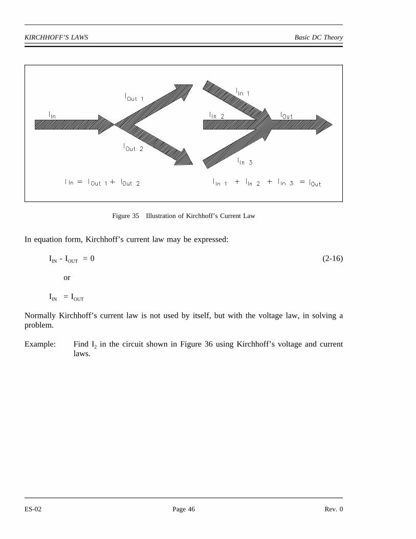
KIRCHHOFF’S LAWS Basic DC Theory
In equation form, Kirchhoff’s current law may be expressed:
Figure 35 Illustration of Kirchhoff’s Current Law
IIN - IOUT = 0 (2-16)
or
IIN = IOUT
Normally Kirchhoff’s current law is not used by itself, but with the voltage law, in solving aproblem.
Example: Find I2 in the circuit shown in Figure 36 using Kirchhoff’s voltage and currentlaws.
ES-02 Page 46 Rev. 0
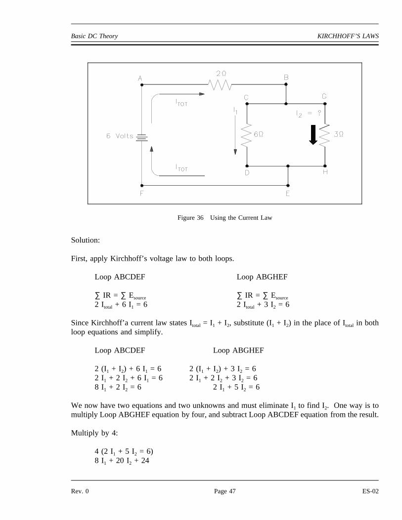
Basic DC Theory KIRCHHOFF’S LAWS
Solution:
Figure 36 Using the Current Law
First, apply Kirchhoff’s voltage law to both loops.
Loop ABCDEF Loop ABGHEF
∑ IR = ∑ Esource ∑ IR = ∑ Esource
2 Itotal + 6 I1 = 6 2 Itotal + 3 I2 = 6
Since Kirchhoff’a current law states Itotal = I1 + I2, substitute (I1 + I2) in the place of Itotal in bothloop equations and simplify.
Loop ABCDEF Loop ABGHEF
2 (I1 + I2) + 6 I1 = 6 2 (I1 + I2) + 3 I2 = 62 I1 + 2 I2 + 6 I1 = 6 2 I1 + 2 I2 + 3 I2 = 68 I1 + 2 I2 = 6 2 I1 + 5 I2 = 6
We now have two equations and two unknowns and must eliminate I1 to find I2. One way is tomultiply Loop ABGHEF equation by four, and subtract Loop ABCDEF equation from the result.
Multiply by 4:
4 (2 I1 + 5 I2 = 6)8 I1 + 20 I2 + 24
Rev. 0 Page 47 ES-02
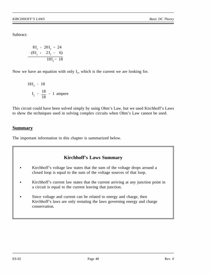
KIRCHHOFF’S LAWS Basic DC Theory
Subtract:
8 I1 20I2 24(8I1 2I2 6)
18I2 18
Now we have an equation with only I2, which is the current we are looking for.
18I2 18
I2
1818
1 ampere
This circuit could have been solved simply by using Ohm’s Law, but we used Kirchhoff’s Lawsto show the techniques used in solving complex circuits when Ohm’s Law cannot be used.
Summary
The important information in this chapter is summarized below.
Kirchhoff’s Laws Summary
Kirchhoff’s voltage law states that the sum of the voltage drops around aclosed loop is equal to the sum of the voltage sources of that loop.
Kirchhoff’s current law states that the current arriving at any junction point ina circuit is equal to the current leaving that junction.
Since voltage and current can be related to energy and charge, thenKirchhoff’s laws are only restating the laws governing energy and chargeconservation.
ES-02 Page 48 Rev. 0
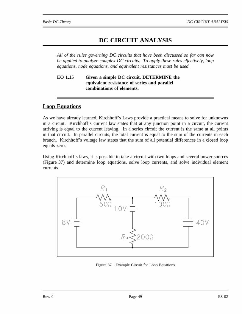
Basic DC Theory DC CIRCUIT ANALYSIS
DC CIRCUIT ANALYSIS
All of the rules governing DC circuits that have been discussed so far can nowbe applied to analyze complex DC circuits. To apply these rules effectively, loopequations, node equations, and equivalent resistances must be used.
EO 1.15 Given a simple DC circuit, DETERMINE theequivalent resistance of series and parallelcombinations of elements.
Loop Equations
As we have already learned, Kirchhoff’s Laws provide a practical means to solve for unknownsin a circuit. Kirchhoff’s current law states that at any junction point in a circuit, the currentarriving is equal to the current leaving. In a series circuit the current is the same at all pointsin that circuit. In parallel circuits, the total current is equal to the sum of the currents in eachbranch. Kirchhoff’s voltage law states that the sum of all potential differences in a closed loopequals zero.
Using Kirchhoff’s laws, it is possible to take a circuit with two loops and several power sources(Figure 37) and determine loop equations, solve loop currents, and solve individual elementcurrents.
Figure 37 Example Circuit for Loop Equations
Rev. 0 Page 49 ES-02
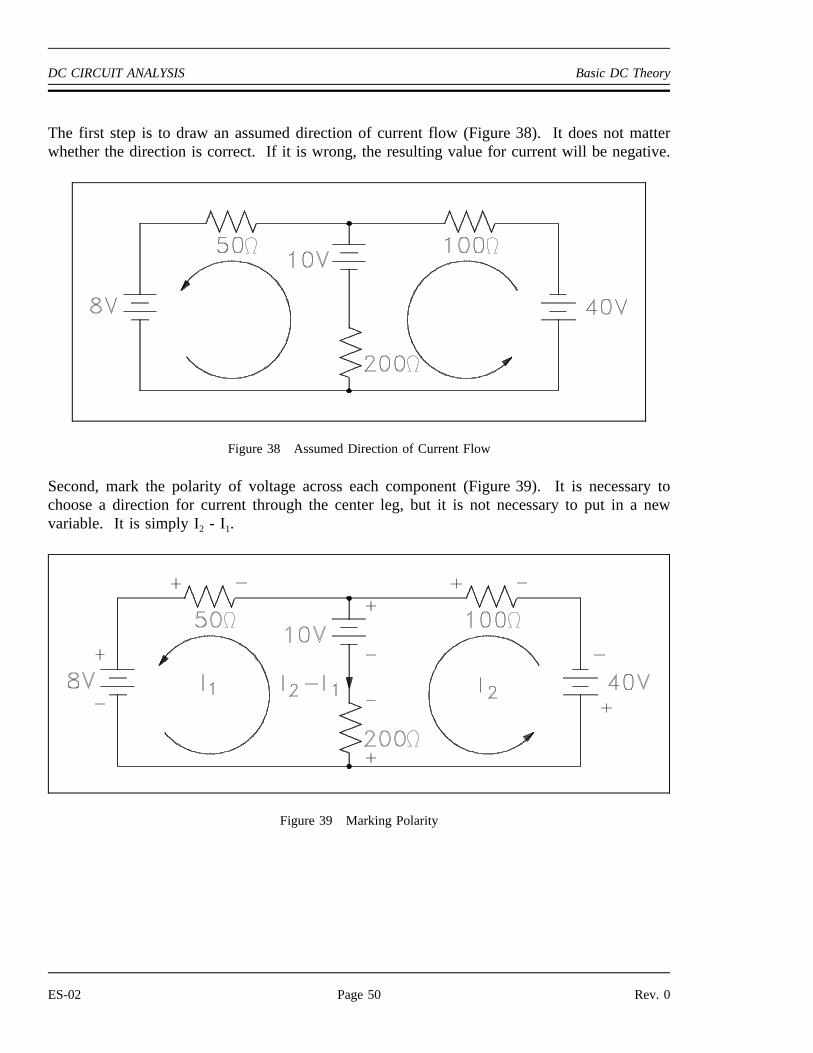
DC CIRCUIT ANALYSIS Basic DC Theory
The first step is to draw an assumed direction of current flow (Figure 38). It does not matterwhether the direction is correct. If it is wrong, the resulting value for current will be negative.
Second, mark the polarity of voltage across each component (Figure 39). It is necessary to
Figure 38 Assumed Direction of Current Flow
choose a direction for current through the center leg, but it is not necessary to put in a newvariable. It is simply I2 - I1.
Figure 39 Marking Polarity
ES-02 Page 50 Rev. 0
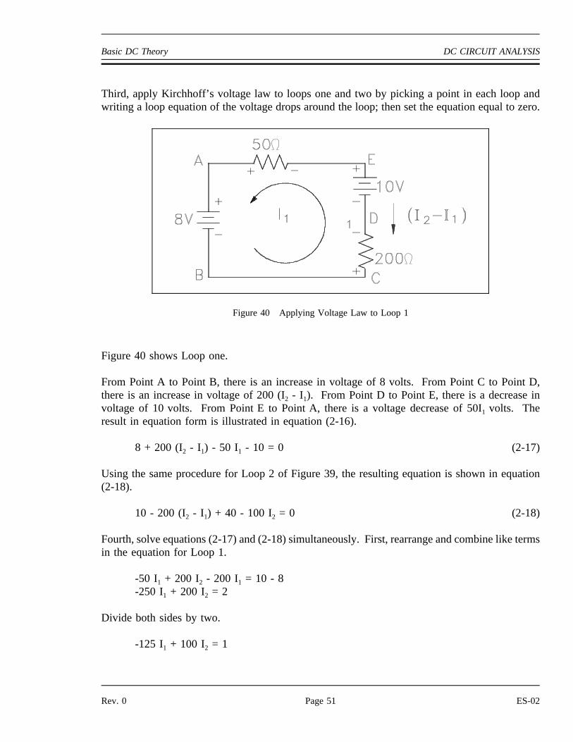
Basic DC Theory DC CIRCUIT ANALYSIS
Third, apply Kirchhoff’s voltage law to loops one and two by picking a point in each loop andwriting a loop equation of the voltage drops around the loop; then set the equation equal to zero.
Figure 40 Applying Voltage Law to Loop 1
Figure 40 shows Loop one.
From Point A to Point B, there is an increase in voltage of 8 volts. From Point C to Point D,there is an increase in voltage of 200 (I2 - I1). From Point D to Point E, there is a decrease involtage of 10 volts. From Point E to Point A, there is a voltage decrease of 50I1 volts. Theresult in equation form is illustrated in equation (2-16).
8 + 200 (I2 - I1) - 50 I1 - 10 = 0 (2-17)
Using the same procedure for Loop 2 of Figure 39, the resulting equation is shown in equation(2-18).
10 - 200 (I2 - I1) + 40 - 100 I2 = 0 (2-18)
Fourth, solve equations (2-17) and (2-18) simultaneously. First, rearrange and combine like termsin the equation for Loop 1.
-50 I1 + 200 I2 - 200 I1 = 10 - 8-250 I1 + 200 I2 = 2
Divide both sides by two.
-125 I1 + 100 I2 = 1
Rev. 0 Page 51 ES-02
DC CIRCUIT ANALYSIS Basic DC Theory
Rearrange and combine like terms in the Loop 2 equation.
200 I2 200 I1 100 I2 10 40
200 I1 300 I2 50
Multiplying the Loop 1 equation by 3, and add it to the Loop 2 equation.
3( 125 I1 100 I2 1) 375 I1 300I2 3
200 I2 300I2 50
175 I1 47
Solving for I1:
175 I1 47
I1
47175
0.2686 amp 268.6 mA
Solving for I2 using the Loop 1 equation:
125 (0.2686) 100 I2 1
100 I2 1 33.58
I2
34.58100
I2 0.3458 amp 345.8 mA
The current flow through R1 (50Ω) is I1. The current flow through R2(100Ω) is I2, and throughR3(200Ω) is I2 - I1:
I3 I2 I1 345.8 mA 268.6 mA
I3 I2 I1 77.2 mA
ES-02 Page 52 Rev. 0
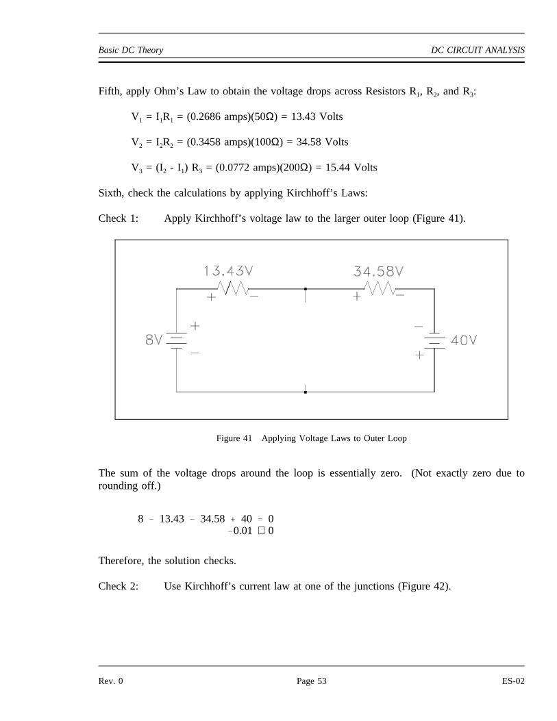
Basic DC Theory DC CIRCUIT ANALYSIS
Fifth, apply Ohm’s Law to obtain the voltage drops across Resistors R1, R2, and R3:
V1 = I1R1 = (0.2686 amps)(50Ω) = 13.43 Volts
V2 = I2R2 = (0.3458 amps)(100Ω) = 34.58 Volts
V3 = (I2 - I1) R3 = (0.0772 amps)(200Ω) = 15.44 Volts
Sixth, check the calculations by applying Kirchhoff’s Laws:
Check 1: Apply Kirchhoff’s voltage law to the larger outer loop (Figure 41).
The sum of the voltage drops around the loop is essentially zero. (Not exactly zero due to
Figure 41 Applying Voltage Laws to Outer Loop
rounding off.)
8 13.43 34.58 40 00.01 ≅ 0
Therefore, the solution checks.
Check 2: Use Kirchhoff’s current law at one of the junctions (Figure 42).
Rev. 0 Page 53 ES-02
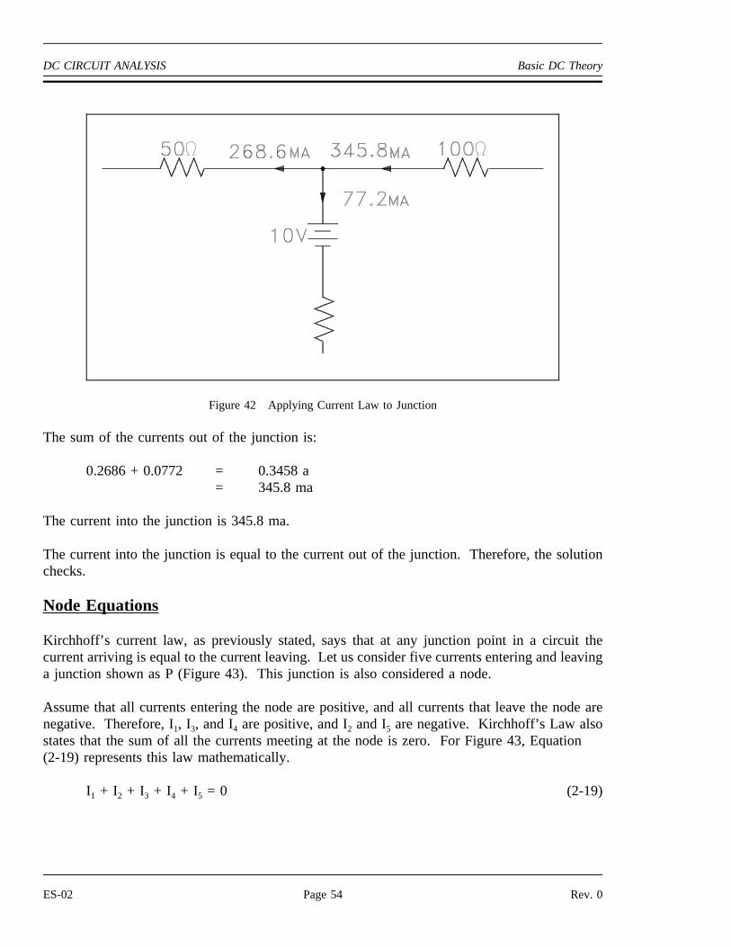
DC CIRCUIT ANALYSIS Basic DC Theory
Figure 42 Applying Current Law to Junction
The sum of the currents out of the junction is:
0.2686 + 0.0772 = 0.3458 a= 345.8 ma
The current into the junction is 345.8 ma.
The current into the junction is equal to the current out of the junction. Therefore, the solutionchecks.
Node Equations
Kirchhoff’s current law, as previously stated, says that at any junction point in a circuit thecurrent arriving is equal to the current leaving. Let us consider five currents entering and leavinga junction shown as P (Figure 43). This junction is also considered a node.
Assume that all currents entering the node are positive, and all currents that leave the node arenegative. Therefore, I1, I3, and I4 are positive, and I2 and I5 are negative. Kirchhoff’s Law alsostates that the sum of all the currents meeting at the node is zero. For Figure 43, Equation(2-19) represents this law mathematically.
I1 + I2 + I3 + I4 + I5 = 0 (2-19)
ES-02 Page 54 Rev. 0
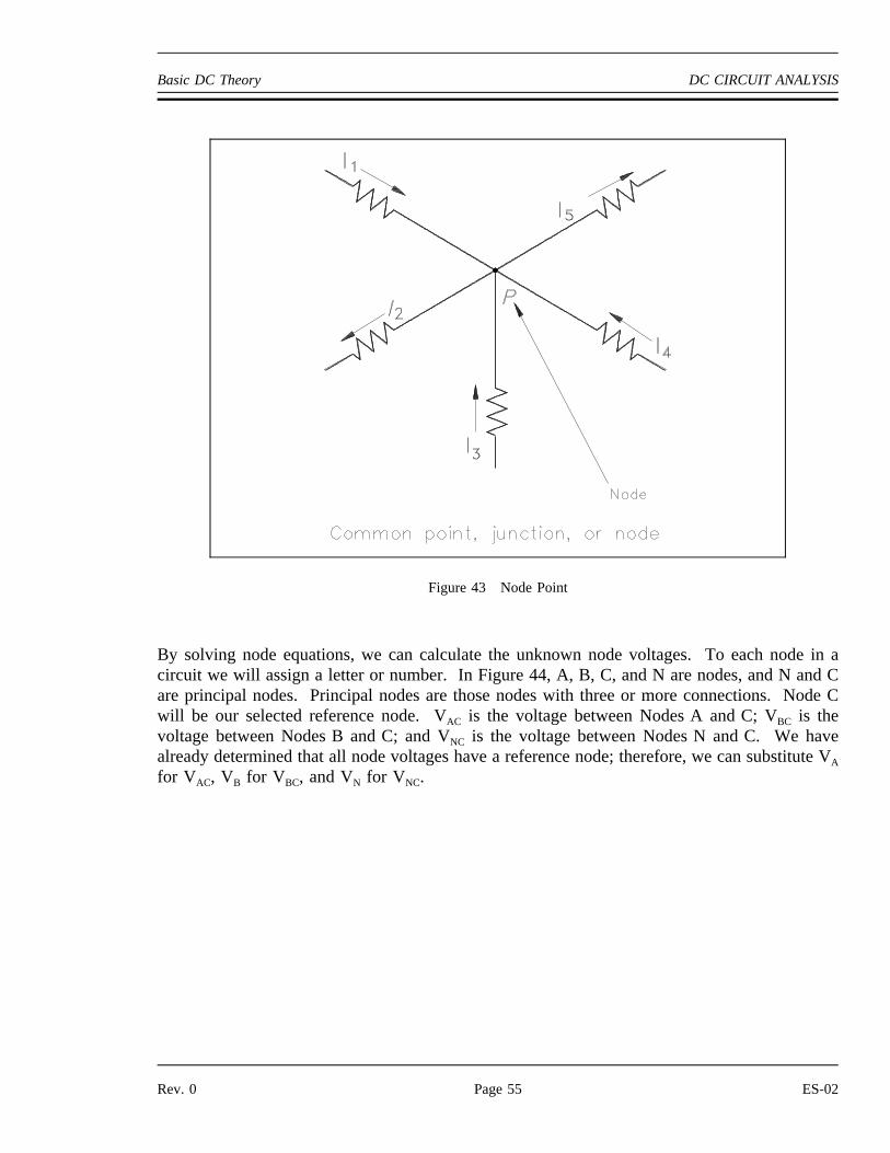
Basic DC Theory DC CIRCUIT ANALYSIS
Figure 43 Node Point
By solving node equations, we can calculate the unknown node voltages. To each node in acircuit we will assign a letter or number. In Figure 44, A, B, C, and N are nodes, and N and Care principal nodes. Principal nodes are those nodes with three or more connections. Node Cwill be our selected reference node. VAC is the voltage between Nodes A and C; VBC is thevoltage between Nodes B and C; and VNC is the voltage between Nodes N and C. We havealready determined that all node voltages have a reference node; therefore, we can substitute VA
for VAC, VB for VBC, and VN for VNC.
Rev. 0 Page 55 ES-02
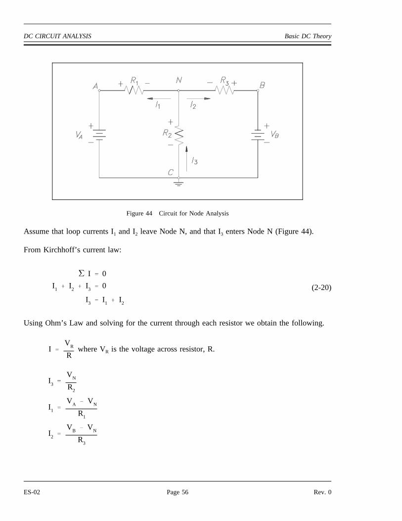
DC CIRCUIT ANALYSIS Basic DC Theory
Figure 44 Circuit for Node Analysis
Assume that loop currents I1 and I2 leave Node N, and that I3 enters Node N (Figure 44).
From Kirchhoff’s current law:
(2-20)
I 0
I1 I2 I3 0
I3 I1 I2
Using Ohm’s Law and solving for the current through each resistor we obtain the following.
where VR is the voltage across resistor, R.IVR
R
I3
VN
R2
I1
VA VN
R1
I2
VB VN
R3
ES-02 Page 56 Rev. 0
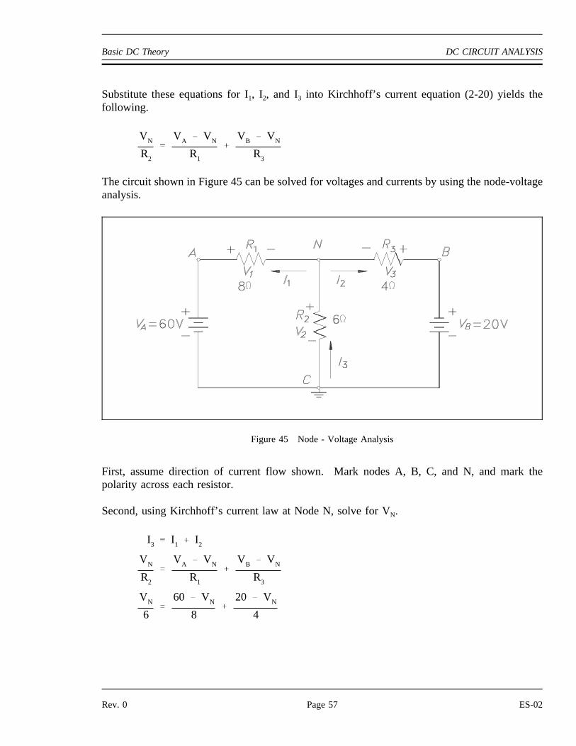
Basic DC Theory DC CIRCUIT ANALYSIS
Substitute these equations for I1, I2, and I3 into Kirchhoff’s current equation (2-20) yields thefollowing.
VN
R2
VA VN
R1
VB VN
R3
The circuit shown in Figure 45 can be solved for voltages and currents by using the node-voltageanalysis.
First, assume direction of current flow shown. Mark nodes A, B, C, and N, and mark the
Figure 45 Node - Voltage Analysis
polarity across each resistor.
Second, using Kirchhoff’s current law at Node N, solve for VN.
I3 I1 I2
VN
R2
VA VN
R1
VB VN
R3
VN
6
60 VN
8
20 VN
4
Rev. 0 Page 57 ES-02
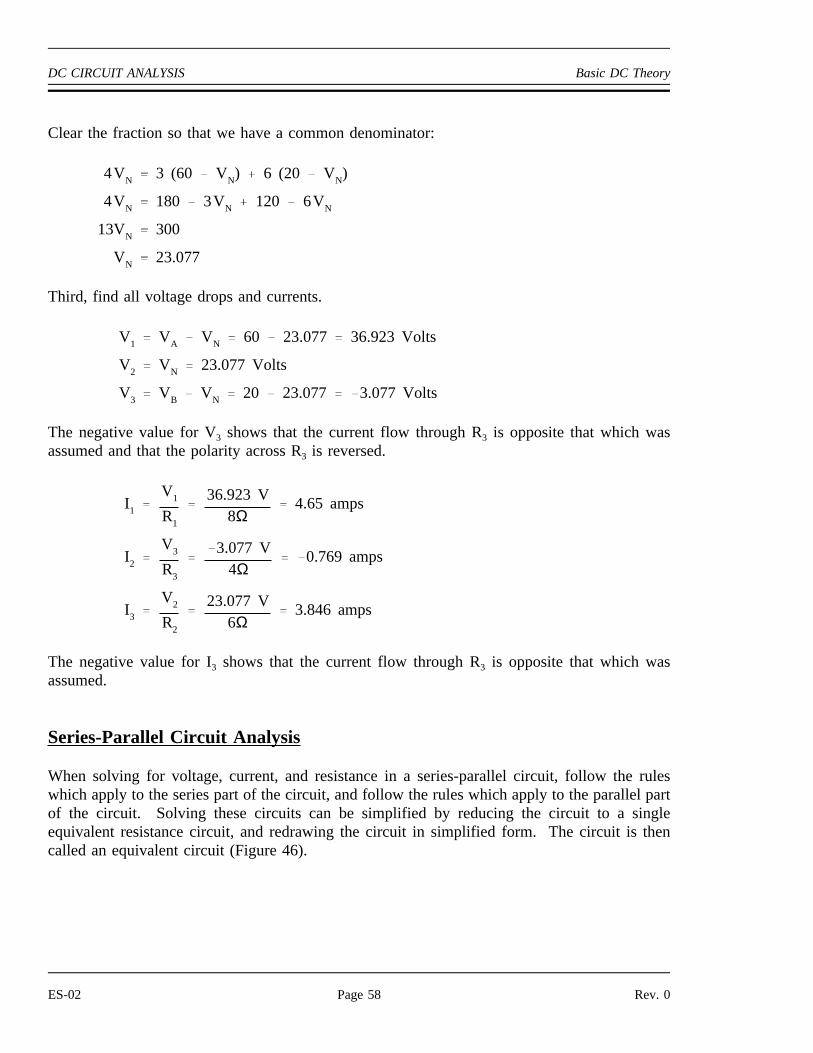
DC CIRCUIT ANALYSIS Basic DC Theory
Clear the fraction so that we have a common denominator:
4VN 3 (60 VN) 6 (20 VN)
4VN 180 3VN 120 6VN
13VN 300
VN 23.077
Third, find all voltage drops and currents.
V1 VA VN 60 23.077 36.923 Volts
V2 VN 23.077 Volts
V3 VB VN 20 23.077 3.077 Volts
The negative value for V3 shows that the current flow through R3 is opposite that which wasassumed and that the polarity across R3 is reversed.
I1
V1
R1
36.923 V8Ω
4.65 amps
I2
V3
R3
3.077 V4Ω
0.769 amps
I3
V2
R2
23.077 V6Ω
3.846 amps
The negative value for I3 shows that the current flow through R3 is opposite that which wasassumed.
Series-Parallel Circuit Analysis
When solving for voltage, current, and resistance in a series-parallel circuit, follow the ruleswhich apply to the series part of the circuit, and follow the rules which apply to the parallel partof the circuit. Solving these circuits can be simplified by reducing the circuit to a singleequivalent resistance circuit, and redrawing the circuit in simplified form. The circuit is thencalled an equivalent circuit (Figure 46).
ES-02 Page 58 Rev. 0
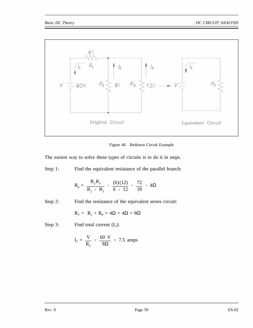
Basic DC Theory DC CIRCUIT ANALYSIS
The easiest way to solve these types of circuits is to do it in steps.
Figure 46 Redrawn Circuit Example
Step 1: Find the equivalent resistance of the parallel branch:
Rp =R2R3
R2 R3
(6) (12)6 12
7218
4Ω
Step 2: Find the resistance of the equivalent series circuit:
RT = R1 + RP = 4Ω + 4Ω = 8Ω
Step 3: Find total current (IT):
IT = VRT
60 V8Ω
7.5 amps
Rev. 0 Page 59 ES-02
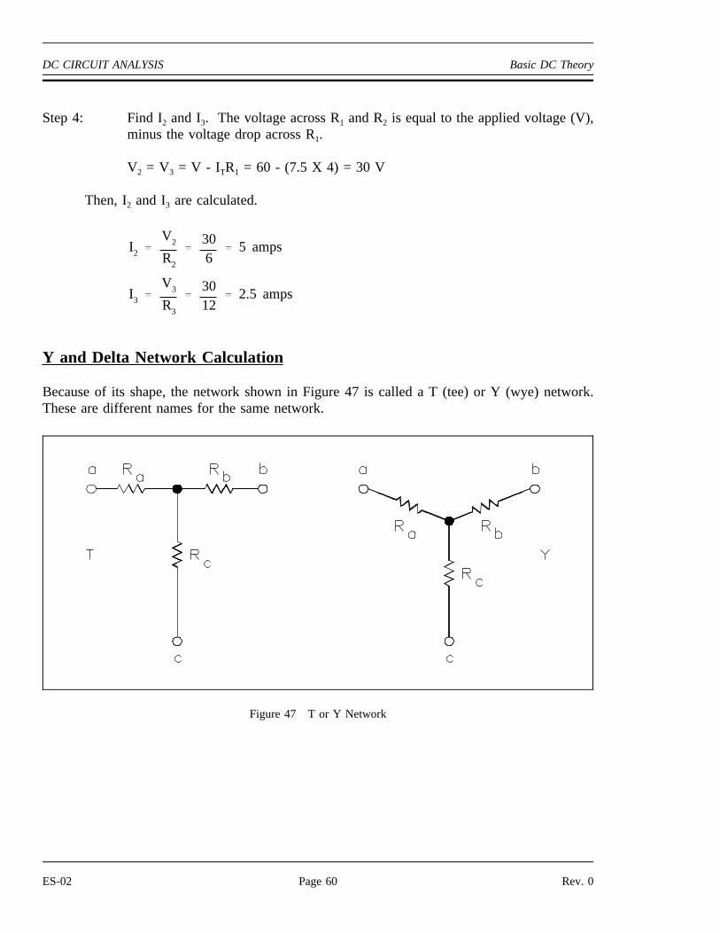
DC CIRCUIT ANALYSIS Basic DC Theory
Step 4: Find I2 and I3. The voltage across R1 and R2 is equal to the applied voltage (V),minus the voltage drop across R1.
V2 = V3 = V - ITR1 = 60 - (7.5 X 4) = 30 V
Then, I2 and I3 are calculated.
I2
V2
R2
306
5 amps
I3
V3
R3
3012
2.5 amps
Y and Delta Network Calculation
Because of its shape, the network shown in Figure 47 is called a T (tee) or Y (wye) network.These are different names for the same network.
Figure 47 T or Y Network
ES-02 Page 60 Rev. 0
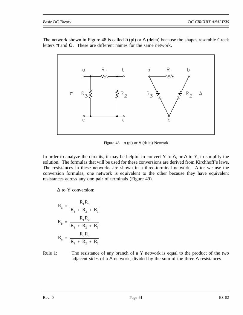
Basic DC Theory DC CIRCUIT ANALYSIS
The network shown in Figure 48 is calledπ (pi) or ∆ (delta) because the shapes resemble Greeklettersπ andΩ. These are different names for the same network.
Figure 48 π (pi) or ∆ (delta) Network
In order to analyze the circuits, it may be helpful to convert Y to∆, or ∆ to Y, to simplify thesolution. The formulas that will be used for these conversions are derived from Kirchhoff’s laws.The resistances in these networks are shown in a three-terminal network. After we use theconversion formulas, one network is equivalent to the other because they have equivalentresistances across any one pair of terminals (Figure 49).
∆ to Y conversion:
Ra
R1R3
R1 R2 R3
Rb
R1R2
R1 R2 R3
Rc
R2R3
R1 R2 R3
Rule 1: The resistance of any branch of a Y network is equal to the product of the twoadjacent sides of a∆ network, divided by the sum of the three∆ resistances.
Rev. 0 Page 61 ES-02
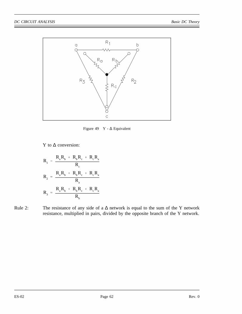
DC CIRCUIT ANALYSIS Basic DC Theory
Figure 49 Y -∆ Equivalent
Y to ∆ conversion:
R1
RaRb RbRc RcRa
Rc
R2
RaRb RbRc RcRa
Ra
R3
RaRb RbRc RcRa
Rb
Rule 2: The resistance of any side of a∆ network is equal to the sum of the Y networkresistance, multiplied in pairs, divided by the opposite branch of the Y network.
ES-02 Page 62 Rev. 0
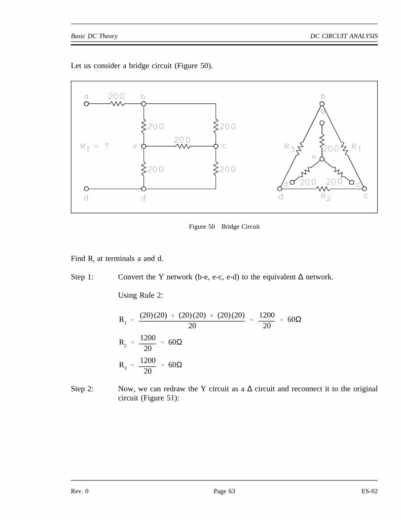
Basic DC Theory DC CIRCUIT ANALYSIS
Let us consider a bridge circuit (Figure 50).
Figure 50 Bridge Circuit
Find Rt at terminals a and d.
Step 1: Convert the Y network (b-e, e-c, e-d) to the equivalent∆ network.
Using Rule 2:
R1
(20)(20) (20)(20) (20)(20)20
120020
60Ω
R2
120020
60Ω
R3
120020
60Ω
Step 2: Now, we can redraw the Y circuit as a∆ circuit and reconnect it to the originalcircuit (Figure 51):
Rev. 0 Page 63 ES-02
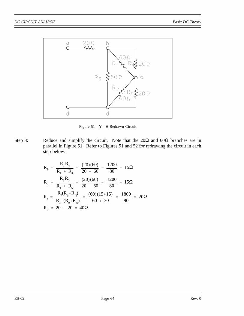
DC CIRCUIT ANALYSIS Basic DC Theory
Figure 51 Y -∆ Redrawn Circuit
Step 3: Reduce and simplify the circuit. Note that the 20Ω and 60Ω branches are inparallel in Figure 51. Refer to Figures 51 and 52 for redrawing the circuit in eachstep below.
RP
R1R4
R1 R4
(20)(60)20 60
120080
15Ω
Rq
R1R5
R1 R5
(20)(60)20 60
120080
15Ω
Rr
R3(Rp RQ)
R3 (Rp RQ)(60)(15 15)
60 30180090
20Ω
RT 20 20 40Ω
ES-02 Page 64 Rev. 0
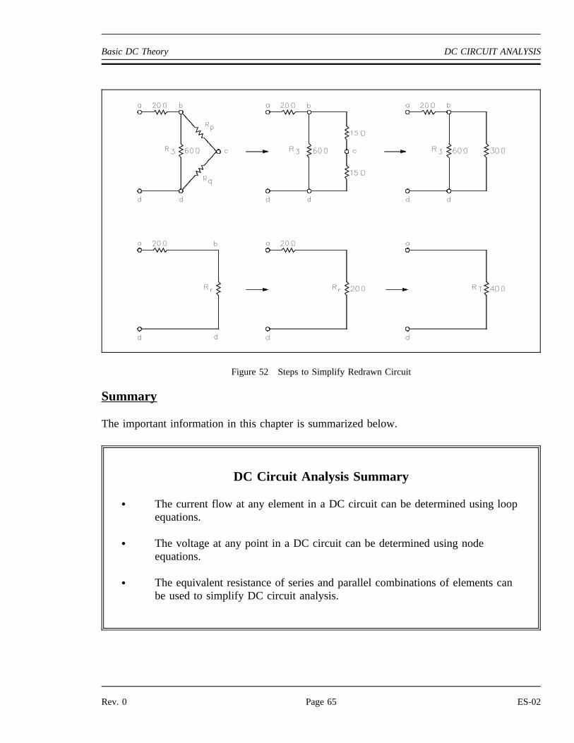
Basic DC Theory DC CIRCUIT ANALYSIS
Summary
Figure 52 Steps to Simplify Redrawn Circuit
The important information in this chapter is summarized below.
DC Circuit Analysis Summary
The current flow at any element in a DC circuit can be determined using loopequations.
The voltage at any point in a DC circuit can be determined using nodeequations.
The equivalent resistance of series and parallel combinations of elements canbe used to simplify DC circuit analysis.
Rev. 0 Page 65 ES-02
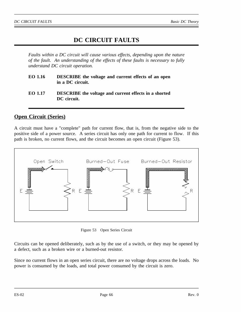
DC CIRCUIT FAULTS Basic DC Theory
DC CIRCUIT FAULTS
Faults within a DC circuit will cause various effects, depending upon the natureof the fault. An understanding of the effects of these faults is necessary to fullyunderstand DC circuit operation.
EO 1.16 DESCRIBE the voltage and current effects of an openin a DC circuit.
EO 1.17 DESCRIBE the voltage and current effects in a shortedDC circuit.
Open Circuit (Series)
A circuit must have a "complete" path for current flow, that is, from the negative side to thepositive side of a power source. A series circuit has only one path for current to flow. If thispath is broken, no current flows, and the circuit becomes an open circuit (Figure 53).
Circuits can be opened deliberately, such as by the use of a switch, or they may be opened by
Figure 53 Open Series Circuit
a defect, such as a broken wire or a burned-out resistor.
Since no current flows in an open series circuit, there are no voltage drops across the loads. Nopower is consumed by the loads, and total power consumed by the circuit is zero.
ES-02 Page 66 Rev. 0
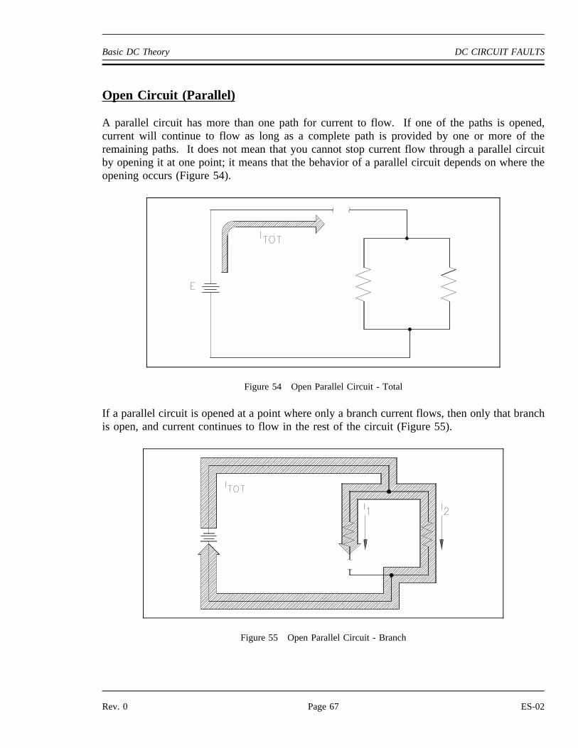
Basic DC Theory DC CIRCUIT FAULTS
Open Circuit (Parallel)
A parallel circuit has more than one path for current to flow. If one of the paths is opened,current will continue to flow as long as a complete path is provided by one or more of theremaining paths. It does not mean that you cannot stop current flow through a parallel circuitby opening it at one point; it means that the behavior of a parallel circuit depends on where theopening occurs (Figure 54).
Figure 54 Open Parallel Circuit - Total
If a parallel circuit is opened at a point where only a branch current flows, then only that branchis open, and current continues to flow in the rest of the circuit (Figure 55).
Figure 55 Open Parallel Circuit - Branch
Rev. 0 Page 67 ES-02
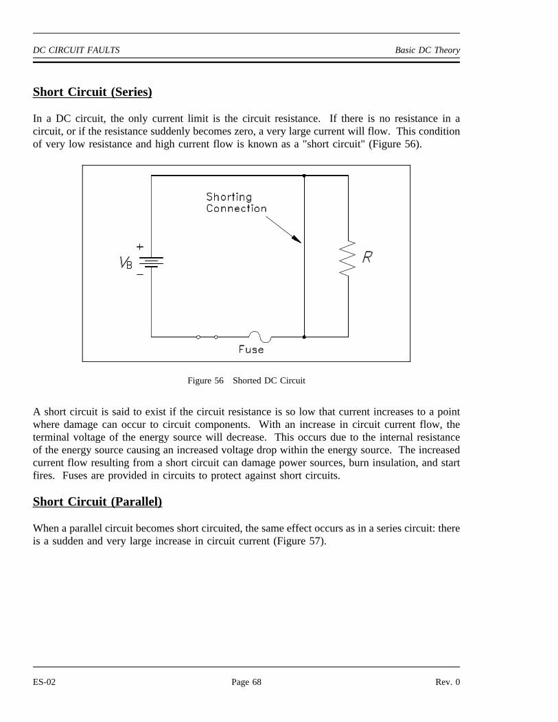
DC CIRCUIT FAULTS Basic DC Theory
Short Circuit (Series)
In a DC circuit, the only current limit is the circuit resistance. If there is no resistance in acircuit, or if the resistance suddenly becomes zero, a very large current will flow. This conditionof very low resistance and high current flow is known as a "short circuit" (Figure 56).
Figure 56 Shorted DC Circuit
A short circuit is said to exist if the circuit resistance is so low that current increases to a pointwhere damage can occur to circuit components. With an increase in circuit current flow, theterminal voltage of the energy source will decrease. This occurs due to the internal resistanceof the energy source causing an increased voltage drop within the energy source. The increasedcurrent flow resulting from a short circuit can damage power sources, burn insulation, and startfires. Fuses are provided in circuits to protect against short circuits.
Short Circuit (Parallel)
When a parallel circuit becomes short circuited, the same effect occurs as in a series circuit: thereis a sudden and very large increase in circuit current (Figure 57).
ES-02 Page 68 Rev. 0
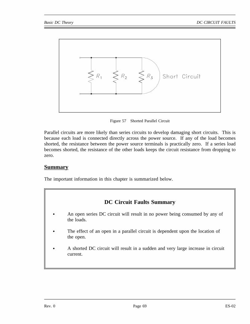
Basic DC Theory DC CIRCUIT FAULTS
Figure 57 Shorted Parallel Circuit
Parallel circuits are more likely than series circuits to develop damaging short circuits. This isbecause each load is connected directly across the power source. If any of the load becomesshorted, the resistance between the power source terminals is practically zero. If a series loadbecomes shorted, the resistance of the other loads keeps the circuit resistance from dropping tozero.
Summary
The important information in this chapter is summarized below.
DC Circuit Faults Summary
An open series DC circuit will result in no power being consumed by any ofthe loads.
The effect of an open in a parallel circuit is dependent upon the location ofthe open.
A shorted DC circuit will result in a sudden and very large increase in circuitcurrent.
Rev. 0 Page 69 ES-02
Basic DC Theory
Intentionally Left Blank
ES-02 Page 70 Rev. 0