document name wecc wind plant dynamic modeling ... wind plant dynamic...for representation of wind...
TRANSCRIPT
Document name WECC Wind Plant Dynamic Modeling Guidelines Category ( ) Regional Reliability Standard
( ) Regional Criteria ( ) Policy (X) Guideline ( ) Report or other ( ) Charter
Document date April 2014 Adopted/approved by
TSS
Date adopted/approved
May 8, 2014
Custodian (entity responsible for maintenance and upkeep)
M&VWG
Stored/filed Physical location: Web URL: http://www.wecc.biz/committees/StandingCommittees/PCC/TSS/MVWG/Shared%20Documents/MVWG%20Approved%20Documents/WECC%20Wind%20Plant%20Dynamic%20Modeling%20Guidelines.pdf
Previous name/number
WECC Wind Power Plant Dynamic Modeling Guide/November 2010
Status (X) in effect ( ) usable, minor formatting/editing required ( ) modification needed ( ) superseded by _____________________ ( ) other _____________________________ ( ) obsolete/archived)
1
Western Electricity Coordinating Council Modeling and Validation Work Group
WECC Wind Power Plant Dynamic Modeling Guide
Prepared by WECC Renewable Energy Modeling Task Force
April 2014
2
Contents 1 Introduction ............................................................................................................................. 4 2 Background ............................................................................................................................. 4 3 General Considerations for Dynamic Simulation of WPP Plants ........................................... 7
3.1 Appropriate Models for Bulk System Simulations .......................................................... 7 3.2 Power Flow Representation ............................................................................................. 7 3.3 Implications of Collector System Equivalencing ............................................................. 8 3.4 Volt/Var Control .............................................................................................................. 9 3.5 Active and Reactive Power Control ................................................................................. 9 3.6 Fault Ride-Through and Representation of Protection Limits ....................................... 10 3.7 Model Parameters ........................................................................................................... 10
4 WECC Generic Models ........................................................................................................ 10 4.1 Technical Specifications for the WECC Generic Models .............................................. 10 4.2 Generic Model Block Diagrams ..................................................................................... 12
4.2.1 Model call ............................................................................................................... 14 4.2.2 Scaling for the WPP size and reactive capability ................................................... 16 4.2.3 Volt/Var controls options ........................................................................................ 16 4.2.4 Active power control options .................................................................................. 17 4.2.5 Representation of Voltage and Frequency Protection ............................................ 18
5 Summary ............................................................................................................................... 18 Appendix A – Detailed Model Description .................................................................................. 19
Generator Model for Type 1 WTG ........................................................................................... 20 Description ............................................................................................................................ 20 Parameters and Default Settings ........................................................................................... 20
Generator Model for Type 2 WTG ........................................................................................... 21 Description ............................................................................................................................ 21 Parameters and Default Settings ........................................................................................... 21
Turbine Model for Type 1 and Type 2 WTG ........................................................................... 22 Description ............................................................................................................................ 22 Parameters and Default Settings ........................................................................................... 22
Pitch Controller (Pseudo-governor) Model for Type 1 and Type 2 WTG ............................... 23 Description ............................................................................................................................ 23 Block Diagram ...................................................................................................................... 23 Parameters and Default Settings ........................................................................................... 24
Excitation/Converter (Rotor Resistance) Control Model for the Type 2 WTG........................ 25 Description ............................................................................................................................ 25 Block Diagram ...................................................................................................................... 25 Parameters and Default Settings ........................................................................................... 25
Generator/Converter Model for Type 3 and Type 4 ................................................................. 26 Description ............................................................................................................................ 26 Block Diagram ...................................................................................................................... 26 Parameters and Default Settings ........................................................................................... 27
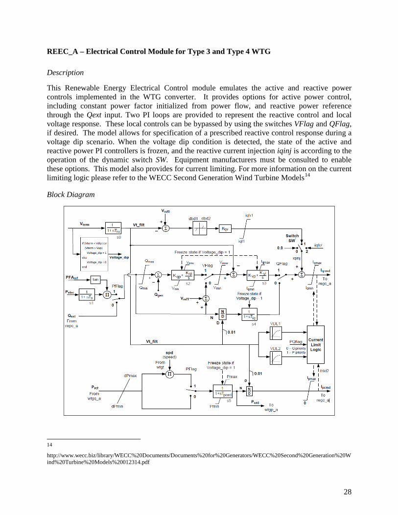
Excitation/Converter Control Model for Type 3 and Type 4 WTG ......................................... 28 Description ............................................................................................................................ 28 Block Diagram ...................................................................................................................... 28
3
Parameters and sample settings ............................................................................................ 29 Aerodynamic Model for Type 3 WTG ..................................................................................... 31
Description ............................................................................................................................ 31 Parameters and Default Settings ........................................................................................... 31
Pitch Controller Model for Type 3 WTG ................................................................................. 32 Description ............................................................................................................................ 32 Parameters and Default Settings ........................................................................................... 32
Torque Controller Model for Type 3 WTG .............................................................................. 33 Description ............................................................................................................................ 33 Parameters and Default Settings ........................................................................................... 33
Plant Controller Model ............................................................................................................. 34 Description ............................................................................................................................ 34 Block Diagram ...................................................................................................................... 34 Parameters and sample settings ............................................................................................ 35
Appendix B – Model Function Calls for GE PSLF, Siemens-PTI PSS®E and PowerWorld Simulator ....................................................................................................................................... 36
Document Version Control ....................................................................................................... 41
4
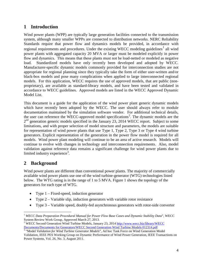
1 Introduction Wind power plants (WPP) are typically large generation facilities connected to the transmission system, although many smaller WPPs are connected to distribution networks. NERC Reliability Standards require that power flow and dynamics models be provided, in accordance with regional requirements and procedures. Under the existing WECC modeling guidelines1 all wind power plants with aggregated capacity 20 MVA or larger must be modeled explicitly in power flow and dynamics. This means that these plants must not be load-netted or modeled as negative load. Standardized models have only recently been developed and adopted by WECC. Manufacturer-specific dynamic models commonly provided for interconnection studies are not appropriate for regional planning since they typically take the form of either user-written and/or black-box models and pose many complications when applied to large interconnected regional models. For this application, WECC requires the use of approved models, that are public (non-proprietary), are available as standard-library models, and have been tested and validated in accordance to WECC guidelines. Approved models are listed in the WECC Approved Dynamic Model List. This document is a guide for the application of the wind power plant generic dynamic models which have recently been adopted by the WECC. The user should always refer to module documentation maintained by the simulation software vendor. For additional technical details, the user can reference the WECC-approved model specifications2. The dynamic models are the 2nd generation generic models specified in the January 23, 2014 WECC report. Subject to some limitations, and with proper selection of model structure and parameters, the models are suitable for representation of wind power plants that use Type 1, Type 2, Type 3 or Type 4 wind turbine generators. Explicit representation of the generation in the power flow model is required for all models. Wind power plant modeling will continue to be an area of active research. Models will continue to evolve with changes in technology and interconnection requirements. Also, model validation against reference data remains a significant challenge for wind power plants due to limited industry experience3. 2 Background Wind power plants are different than conventional power plants. The majority of commercially available wind power plants use one of the wind turbine-generator (WTG) technologies listed below. The WTG rating is in the range of 1 to 5 MVA. Figure 1 shows the topology of the generators for each type of WTG.
• Type 1 – Fixed-speed, induction generator • Type 2 – Variable slip, induction generators with variable rotor resistance • Type 3 – Variable speed, doubly-fed asynchronous generators with rotor-side converter
1 WECC Data Preparation Procedural Manual for Power Flow Base Cases and Dynamic Stability Data”, WECC System Review Work Group, Approved March 27, 2013. 2 WECC Second Generation Wind Turbine Models, January 23, 2014 http://www.wecc.biz/library/WECC Documents/Documents for Generators/WECC Second Generation Wind Turbine Models 012314.pdf 3 “Model Validation for Wind Turbine Generator Models”, Ad hoc Task Force on Wind Generation Model Validation, IEEE PES Working Group on Dynamic Performance of Wind Power Generation, IEEE Transactions on Power Systems, Vol. 26, No. 3, August 2011.
5
• Type 4 – Variable speed generators with full converter interface
Figure 1 – Classification of WTGs Based on Generator Topology and Grid Interface
A Type 1 WTG is an induction generator with relatively simple controls. The torque speed characteristic is very steep (about 1% slip at rated torque), which means that these generators operate at nearly constant speed. As with any induction generator, the Type 1 WTGs absorb reactive power. Most commercial Type 1 WTGs use multiple stages of switched capacitor banks at the turbine terminals to correct the steady-state power factor at the WTG terminals to unity, over the range of power output. With a slow varying wind speed, the individual capacitors switch in and out. A large temporary reactive power imbalance can occur due to changes in wind speed or grid conditions. Smaller (less than 1 MW) type 1 WTGs typically use stall regulation4 where the blades of the turbine are bolted to the hub, while larger type 1 WTGs use active-stall control whether the blades are pitched at low wind speeds to achieve greater turbine efficiency and at high wind speeds pitching is used to effect stall. Blade pitching also contributes to stability following a fault. Type 2 WTGs are also directly-coupled induction generators and use power factor correction capacitors. However, the dynamic behavior is different because the y can rapidly adjust the effective rotor resistance with power electronics. The rotor resistance control (fast) and the pitch control (slower) work in concert to control speed, reduce mechanical stress, and improve stability during a disturbance. WPPs with Type 1 and Type 2 WTGs typically have plant-level reactive compensation equipment to meet steady-state and dynamic reactive power requirements. External reactive support also helps the plant meet voltage ride-through requirements. The steady-state and dynamic characteristics of Type 3 and Type 4 WTGs are dominated by the power converter. The converters allow the machine to operate over a wider range of speeds, and control active and reactive power independently, so long as the total current output of the unit is 4 CIGRE Technical Brochure 328, Modeling and Dynamic Behavior of Wind Generation as it Relates to Power System Control and Dynamic Performance, August 2007 (www.e-cigre.org)
genera tor
full power
PlantFeede rs
actodc
dctoac
gene rator
partia l power
PlantFeeders
actodc
dctoac
gene rator
Slip poweras heat loss
Pla ntFee ders
PF controlcapacitor s
actodc
gene rator
PlantFeeders
PF controlcapacitor s
Type 1 Type 2
Type 3 Type 4
6
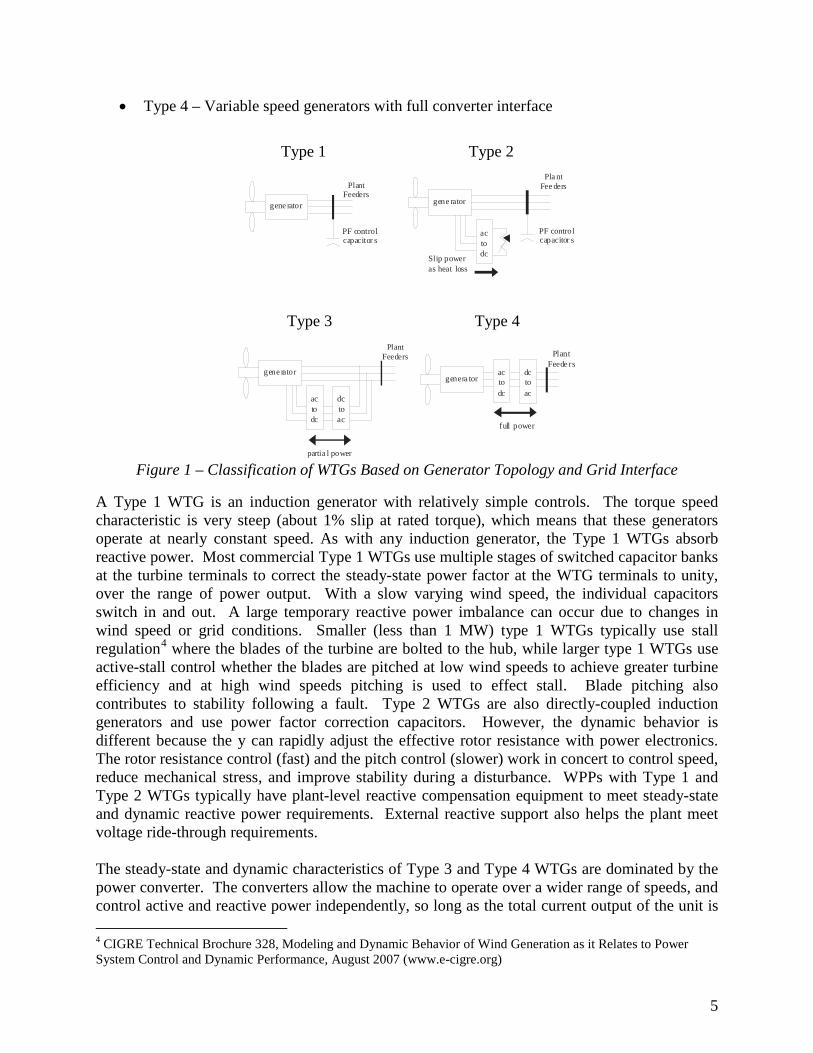
within the current limits of the converter. This means that Type 3 and Type 4 WTGs have the capability to participate in steady-state and dynamic volt/var control. Type 3 and Type 4 WTGs also use blade pitch control to optimize energy capture. It should be noted, however, that in some cases with Type 3 and Type 4 WPPs plant level reactive compensation – typically in the form of mechanically switched capacitors controlled through a plant level controller – is also deployed, since it is not possible to effectively translate all the reactive capability of the WTGs, acting through the collector system at the point of common coupling. Because they use grid-side voltage-source power converters, Type 3 and Type 4 WTGs tend to be more flexible in terms of reactive power control and disturbance tolerance. Even so, wind power plants that use Type 1 and Type 2 WTGs can be designed to have comparable performance by supplementing them with external plant-level reactive-power support devices such as STATCOMs and SVCs. Figure 2 shows the topology of a large wind power plant. The WTGs connect to medium voltage radial feeders (Figure 2), each of which can be several miles long. Each WTG has a dedicated step-up transformer. Most plants have a plant controller that coordinates the operation of passive (capacitors) and active (SVC/STATCOM or the WTG converters) in order to meet requirements at the point of connection. Type 3 and Type 4 WTGs typically receive a power factor reference from the plant controller5 and plant-level reactive power support equipment, if present. The plant controller processes measurements at the point of interconnection, as well as commands issued from the fleet remote operations center or directly from the transmission system operator.
Figure 2 – Typical WPP Topology Wind power plants are considered non-dispatchable because the energy source (wind) is variable. However, reactive power within the WPP may be dispatchable within the capability of the WTGs and plant-level reactive compensation, where dynamic reactive capability is provided
5 Although not used commonly, the plant controller could also provide active power to the inverters to prevent the plant output from exceeding a certain limit.
7
(e.g. Type 3 and Type 4 WTGs or WPPs with an SVC, STATCOM, or controlled switched shunt compensation at the point of interconnection). 3 General Considerations for Dynamic Simulation of WPP Plants 3.1 Appropriate Models for Bulk System Simulations
The WECC generic models were designed for large transmission planning studies that involve a large network, and a large set of generators, loads and other dynamic components. The objective is to assess dynamic performance of the system, particularly recovery dynamics following grid-side disturbances such as transmission-level faults. In this context, WECC uses positive-sequence power flow and dynamic models that provide a good representation of recovery dynamics using integration time steps in the range of 1 to 5 milliseconds. This approach does not allow for detailed representation of very fast controls and response to imbalanced disturbances. It should be noted that these positive-sequence generic dynamic models for inverter-based generators tend to produce a short-duration (a cycle or shorter) voltage spike at fault clearing. These spikes should be ignored in most cases, as they do not representative the performance of actual hardware. In reality such momentary spikes are far smaller in magnitude and duration for the actual equipment due to the very fast converter controls. They are simply a consequence of the model's limited bandwidth, integration time step, and the way the current injection models interface with the network solution6. 3.2 Power Flow Representation
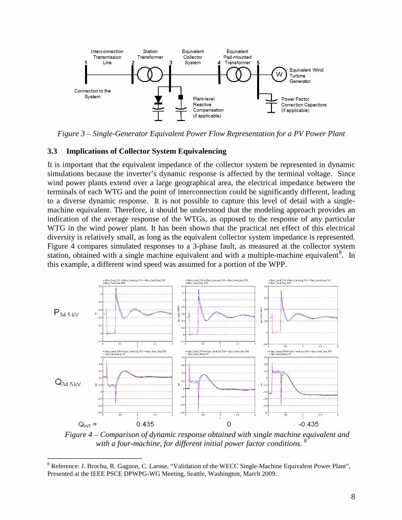
The WECC generic dynamic models described in this guideline assume that the wind power plant is represented explicitly as a generator in power flow. For bulk system studies, it is impractical and unnecessary to model the collector system network inside the plant to the level of detail shown in Figure 2. In accordance with the WECC Wind Plant Power Flow Modeling Guide7, wind power plants must be represented by a simplified system consisting of one or more equivalent generators and unit transformers, equivalent collector system, substation transformer, and plant-level reactive support system, if present. For most wind power plants, the single-generator equivalent model shown in Figure 3 is adequate for bulk-level power flow and dynamic simulations. The WECC Wind Plant Power Flow Modeling Guide also describes a methodology to derive the parameters for the single-machine representation, including a way to derive the collector system equivalent from design data.
6 This issue is discussed in great detail in section 3.2.4 of the report: Generic Models and Model Validation for Wind and Solar PV Generation: Technical Update. EPRI, Palo Alto, CA: 2011, 1021763. (http://www.epri.com/abstracts/Pages/ProductAbstract.aspx?ProductId=000000000001021763) 7 WECC Wind Power Plant Power Flow Modeling Guide, WECC Renewable Energy Modeling Task Force, Approved May 2010.
8
Figure 3 – Single-Generator Equivalent Power Flow Representation for a PV Power Plant 3.3 Implications of Collector System Equivalencing
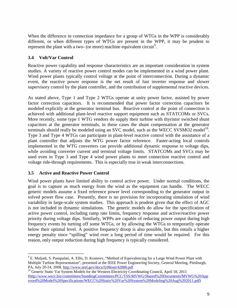
It is important that the equivalent impedance of the collector system be represented in dynamic simulations because the inverter’s dynamic response is affected by the terminal voltage. Since wind power plants extend over a large geographical area, the electrical impedance between the terminals of each WTG and the point of interconnection could be significantly different, leading to a diverse dynamic response. It is not possible to capture this level of detail with a single-machine equivalent. Therefore, it should be understood that the modeling approach provides an indication of the average response of the WTGs, as opposed to the response of any particular WTG in the wind power plant. It has been shown that the practical net effect of this electrical diversity is relatively small, as long as the equivalent collector system impedance is represented. Figure 4 compares simulated responses to a 3-phase fault, as measured at the collector system station, obtained with a single machine equivalent and with a multiple-machine equivalent8. In this example, a different wind speed was assumed for a portion of the WPP.
Figure 4 – Comparison of dynamic response obtained with single machine equivalent and
with a four-machine, for different initial power factor conditions. 8
8 Reference: J. Brochu, R. Gagnon, C. Larose, “Validation of the WECC Single-Machine Equivalent Power Plant”, Presented at the IEEE PSCE DPWPG-WG Meeting, Seattle, Washington, March 2009.
9
When the difference in connection impedance for a group of WTGs in the WPP is considerably different, or when different types of WTGs are present in the WPP, it may be prudent to represent the plant with a two- (or more) machine equivalent circuit9. 3.4 Volt/Var Control
Reactive power capability and response characteristics are an important consideration in system studies. A variety of reactive power control modes can be implemented in a wind power plant. Wind power plants typically control voltage at the point of interconnection. During a dynamic event, the reactive power response is the net result of fast inverter response and slower supervisory control by the plant controller, and the contribution of supplemental reactive devices. As stated above, Type 1 and Type 2 WTGs operate at unity power factor, assisted by power factor correction capacitors. It is recommended that power factor correction capacitors be modeled explicitly at the generator terminal bus. Reactive control at the point of connection is achieved with additional plant-level reactive support equipment such as STATCOMs or SVCs. More recently, some type 1 WTG vendors do supply their turbine with thyristor switched shunt capacitors at the generator terminals, in these cases the shunt compensation at the generator terminals should really be modeled using an SVC model, such as the WECC SVSMO2 model10. Type 3 and Type 4 WTGs can participate in plant-level reactive control with the assistance of a plant controller that adjusts the WTG power factor reference. Faster-acting local controls implemented in the WTG converters can provide additional dynamic response to voltage dips, while avoiding converter current and terminal voltage limits. STATCOMs and SVCs may be used even in Type 3 and Type 4 wind power plants to meet connection reactive control and voltage ride-through requirements. This is especially true in weak interconnections. 3.5 Active and Reactive Power Control
Wind power plants have limited ability to control active power. Under normal conditions, the goal is to capture as much energy from the wind as the equipment can handle. The WECC generic models assume a fixed reference power level corresponding to the generator output in solved power flow case. Presently, there is no provision for incorporating simulation of wind variability in large-scale system studies. This approach is prudent given that the effect of AGC is not included in dynamic simulations. The generic models do allow for the specification of active power control, including ramp rate limits, frequency response and active/reactive power priority during voltage dips. Similarly, WPPs are capable of reducing power output during high frequency events by turning off some WTGs, or by allowing the WTGs to temporarily operate below their optimal level. A positive frequency droop is also possible, but this entails a higher energy penalty since “spilling” wind over a long period of time would be required. For this reason, only output reduction during high frequency is typically considered.
9 E. Muljadi, S. Pasupulati, A. Ellis, D. Kosterev, “Method of Equivalencing for a Large Wind Power Plant with Multiple Turbine Representation”, presented at the IEEE Power Engineering Society, General Meeting, Pittsburgh, PA, July 20-24, 2008, http://www.nrel.gov/docs/fy08osti/42886.pdf 10 Generic Static Var System Models for the Western Electricity Coordinating Council, April 18, 2011 (http://www.wecc.biz/committees/StandingCommittees/PCC/TSS/MVWG/Shared%20Documents/MVWG%20Approved%20Model%20Specifications/WECC%20Static%20Var%20System%20Modeling%20Aug%202011.pdf)
10
Type 3 and Type 4 WTGs do not inherently have inertial response because these machines are controlled by the power electronic converters that effectively isolate the generator from the grid. However, some manufacturers offer a “synthetic inertia” feature, which is achieved by temporarily drawing energy out of the rotating turbine-generator shaft and thus allowing the machine to slow down or speed up as a function of grid frequency. The versions of WECC generic models discussed in this document do not include provisions to represent synthetic inertia capability. 3.6 Fault Ride-Through and Representation of Protection Limits
Various types of controls are used to keep the WTG from tripping within the voltage ride-through envelope. For example, Type 3 and Type 4 WTGs might use a dc-chopper circuit or an ac active-crowbar mechanism to protect against DC link over-voltage, which can occur during sever faults on the grid side. WTGs also pitch the blades in an effort to improve stability during fault recovery. This is particularly important for Type 1 and Type 2 WTGs. The new WECC generic models were specifically modified to have higher fidelity during fault conditions. However, it is not possible to capture the complex behavior of actual hardware using positive-sequence models. This limitation is acceptable because system studies focus on the characteristics of the dynamic recovery, rather than on system conditions during the fault. Considering that terminal voltage can vary significantly across the plant, a single machine representation has obvious limitations with respect to assessment of voltage ride through11. 3.7 Model Parameters
As with any other equipment, appropriate parameters must be selected to represent the dynamic behavior of the corresponding wind power plant. Default parameters provided are intended only for model testing, and do not represent any particular project. Consistent with established WECC practice, input from the plant operator and equipment manufacturer is required to correctly parameterize the model12. This is also true for the power flow representation.
4 WECC Generic Models This section contains a general description of the WECC generic models based on REMTF technical specifications approved by WECC. The models are available as standard-library models in commercial simulation platforms used in WECC. The purpose of this document is to help model users understand the limitations of the models, the model structure, user-selectable options, requirements for scaling the plant size, and representation of protection settings.
4.1 Technical Specifications for the WECC Generic Models
The WECC generic models for wind power plants are based on the following technical specifications:
11 See section 5 of the report WECC Type 3 Wind Turbine Generator Model –Phase II, January 23, 2014 for a more detailed discussion of some of these issues, such as the active-crowbar mechanism. (http://www.wecc.biz/library/WECC%20Documents/Documents%20for%20Generators/WECC%20Type%203%20Wind%20Turbine%20Generator%20Model%20-%20Phase%20II%20012314.pdf) 12 Periodic model validation is also required. This topic is addressed in a separate WECC guideline.
11
• The models shall be non-proprietary and accessible to transmission planners and grid operators without the need for non-disclosure agreements.
• The models are expected to provide a reasonably good representation of dynamic electrical performance of wind power plant at the point of interconnection with the utility grid, and not inside the wind power plant collector system.
• Studies of interest to be performed using the generic models are electrical disturbances, not wind disturbances. Electrical disturbances of interest are primarily balanced transmission grid faults, not internal to the wind power plant, typically of 3 - 6 cycles duration. Other transient events such as capacitor switching and loss of generation can also be simulated.
• The accuracy of generic models during unbalanced events needs further research and development. At the present time, there is no standard guideline.
• Manufacturers and model users (with guidance from the manufacturers) shall have the ability to represent differences among generators with the same topology by selecting appropriate model parameters.
• Simulations performed using these models typically cover a 20-30 second time frame, with a ¼ cycle integration time step. Wind speed is assumed to be constant during this period.
• The generic models shall be functional models suitable for the analysis and simulation of large-scale power systems. Their frequency range of validity is from dc to approximately 10 Hz.
• A generic model shall include the means for external modules to be connected to the model, e.g., protection functions.
• The models shall be initialized based on the power-flow power dispatch. For power less than rated, blade pitch will be set at minimum and wind speed at an appropriate (constant) value. For rated power, a user-specified wind speed (greater than or equal to rated speed) will be held constant and used to determine initial conditions.
• For type 2 WTG, a look-up table of power versus slip shall be provided. • For converter-based WTG (Type 3 and Type 4) appropriate limits for the converter
power and current shall be modeled. • Power level of interest shall be primarily 100% of rated power, with wind speed in the
range of 100% to 130% of rated wind speed. However, performance should be correct, within a reasonable tolerance, for the variables of interest (current, active power, reactive power and power factor), within a range of 25% to 100% of rated power.
• In addition to the overall machine inertia, the first shaft torsional mode characteristics shall be user-specified in terms of frequency, turbine inertia, and damping factor, with calculations performed internally to determine appropriate torsional model parameters to match the modal frequency. The model should be able to represent one or two masses.
• The models shall be applicable to strong and weak systems with a short circuit ratio of 3 and higher at the point of interconnection. The models should not behave erratically when the SCR is low. However, it should be noted that these generic models are NOT intended for studying parts of the system that are subject to very low short-circuit levels. In such cases, detailed vendor specific models may be needed.
• Aerodynamic characteristics shall be represented with an approximate performance model that can simulate blade pitching, assuming constant wind speed, without the need for traditional CP curves.
12
• Shunt capacitors and any other reactive support equipment shall be modeled separately with existing standard models.
• The models shall have provision to detect voltage dip conditions and switch to alternative control modes as necessary.
WECC approved the use of four generic dynamic models for wind power plants. A detailed model specification document is available on the WECC website13. A brief description is given below of these models for completeness. Where discrepancies may inadvertently exist between the descriptions given below and the detailed model specification document, precedence should be given to the specification document. 4.2 Generic Model Block Diagrams
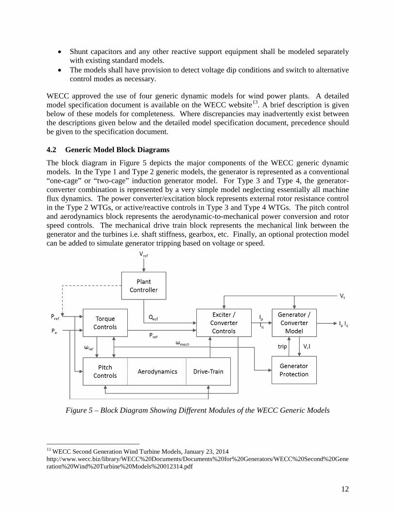
The block diagram in Figure 5 depicts the major components of the WECC generic dynamic models. In the Type 1 and Type 2 generic models, the generator is represented as a conventional “one-cage” or “two-cage” induction generator model. For Type 3 and Type 4, the generator-converter combination is represented by a very simple model neglecting essentially all machine flux dynamics. The power converter/excitation block represents external rotor resistance control in the Type 2 WTGs, or active/reactive controls in Type 3 and Type 4 WTGs. The pitch control and aerodynamics block represents the aerodynamic-to-mechanical power conversion and rotor speed controls. The mechanical drive train block represents the mechanical link between the generator and the turbines i.e. shaft stiffness, gearbox, etc. Finally, an optional protection model can be added to simulate generator tripping based on voltage or speed.
Figure 5 – Block Diagram Showing Different Modules of the WECC Generic Models
13 WECC Second Generation Wind Turbine Models, January 23, 2014 http://www.wecc.biz/library/WECC%20Documents/Documents%20for%20Generators/WECC%20Second%20Generation%20Wind%20Turbine%20Models%20012314.pdf
13
The second-generation wind power plant models require the use of the modules described below. Appendix A contains a detailed description of the modules, including block diagram, list of parameters, internal variables and output channels. For wind power plants based on Type 1 and Type 2 WTG, the required modules are listed below. Updates with respect to the first-generation of WECC generic models are noted.
• WT1G and WT2G modules, used to represent the generator in Type 1 and Type 2 WTGs, respectively. A standard induction machine model is used.
• WT1T and WT2T modules, used to represent the turbine in Type 1 and Type 2 WTGs, respectively.
• WT1P_B module, used to represent the aerodynamic (pitch) controls for Type 1 and Type 2 WTGs. This module was modified to more accurately reflect pitch control action during and shortly after a fault.
• WT2E module, used to represent the rotor resistance control for Type 2 WTGs. Strictly speaking, only the WTG1/WTG2 module is required to run a simulation; however, the rest of the modules are needed to enable control functionality. For wind power plants based on Type 3 and 4 WTGs, the required modules are listed below. The second-generation model specifications are significantly improved with respect to the previous WECC generic model, in terms of structure and functionality.
• REGC_A module, used to represent the generator/converter. It processes the real and reactive current commands, and outputs real and reactive current injection into the grid model.
• REEC_A module, used to represent the WTG electrical controls. It acts on the active and reactive power reference from the REPC_A module, with feedback of terminal voltage and generator power output, and provides real and reactive current commands to the REGC_A module.
• REPC_A modules, used to represent the plant controller. It processes voltage and reactive power output to emulate volt/var control at the plant level. It also processes frequency and active power output to emulate active power control. This module provides active reactive power command to the REEC_A module.
• WTGT_A module, used to represent the turbine. • WTGAR_A module, used to represent the aerodynamic conversion (Type 3 only). • WTGPT_A module, used to represent the pitch controller (Type 3 only). • WTGTQ_A module, used to represent the torque controller (Type 3 only).
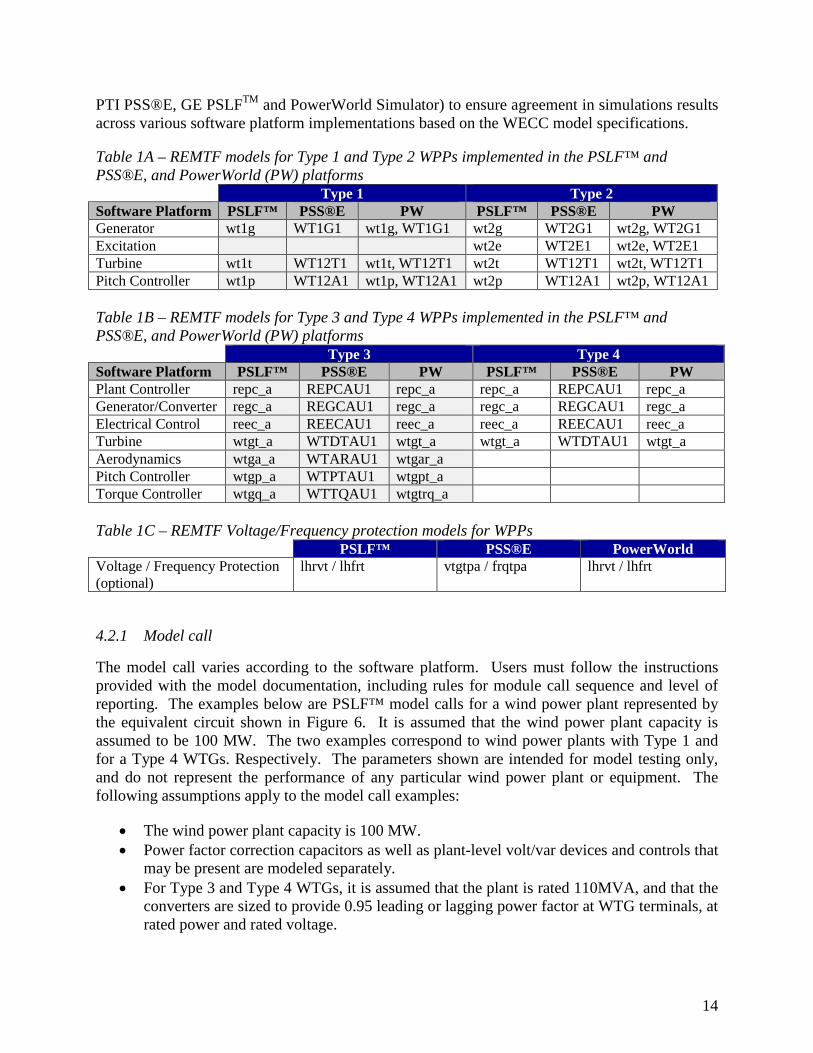
Strictly speaking, only the REGC_A module is required to run a simulation; however, the rest of the modules are needed to enable control functionality. Standard generator protection models can be used to indicate the conditions that could lead to generator tripping. A list of available simulation modules for Siemens PTI PSS®E, GE PSLF™, and PowerWorld Simulator is shown in Table 1. Although there may be differences in the program implementation the models are functionally equivalent and have the same set of parameters. Also, testing was done to compare results among three software platforms (Siemens
14
PTI PSS®E, GE PSLFTM and PowerWorld Simulator) to ensure agreement in simulations results across various software platform implementations based on the WECC model specifications. Table 1A – REMTF models for Type 1 and Type 2 WPPs implemented in the PSLF™ and PSS®E, and PowerWorld (PW) platforms Type 1 Type 2 Software Platform PSLF™ PSS®E PW PSLF™ PSS®E PW Generator wt1g WT1G1 wt1g, WT1G1 wt2g WT2G1 wt2g, WT2G1 Excitation wt2e WT2E1 wt2e, WT2E1 Turbine wt1t WT12T1 wt1t, WT12T1 wt2t WT12T1 wt2t, WT12T1 Pitch Controller wt1p WT12A1 wt1p, WT12A1 wt2p WT12A1 wt2p, WT12A1 Table 1B – REMTF models for Type 3 and Type 4 WPPs implemented in the PSLF™ and PSS®E, and PowerWorld (PW) platforms Type 3 Type 4 Software Platform PSLF™ PSS®E PW PSLF™ PSS®E PW Plant Controller repc_a REPCAU1 repc_a repc_a REPCAU1 repc_a Generator/Converter regc_a REGCAU1 regc_a regc_a REGCAU1 regc_a Electrical Control reec_a REECAU1 reec_a reec_a REECAU1 reec_a Turbine wtgt_a WTDTAU1 wtgt_a wtgt_a WTDTAU1 wtgt_a Aerodynamics wtga_a WTARAU1 wtgar_a Pitch Controller wtgp_a WTPTAU1 wtgpt_a Torque Controller wtgq_a WTTQAU1 wtgtrq_a Table 1C – REMTF Voltage/Frequency protection models for WPPs PSLF™ PSS®E PowerWorld Voltage / Frequency Protection (optional)
lhrvt / lhfrt vtgtpa / frqtpa lhrvt / lhfrt
4.2.1 Model call
The model call varies according to the software platform. Users must follow the instructions provided with the model documentation, including rules for module call sequence and level of reporting. The examples below are PSLF™ model calls for a wind power plant represented by the equivalent circuit shown in Figure 6. It is assumed that the wind power plant capacity is assumed to be 100 MW. The two examples correspond to wind power plants with Type 1 and for a Type 4 WTGs. Respectively. The parameters shown are intended for model testing only, and do not represent the performance of any particular wind power plant or equipment. The following assumptions apply to the model call examples:
• The wind power plant capacity is 100 MW. • Power factor correction capacitors as well as plant-level volt/var devices and controls that
may be present are modeled separately. • For Type 3 and Type 4 WTGs, it is assumed that the plant is rated 110MVA, and that the
converters are sized to provide 0.95 leading or lagging power factor at WTG terminals, at rated power and rated voltage.
15
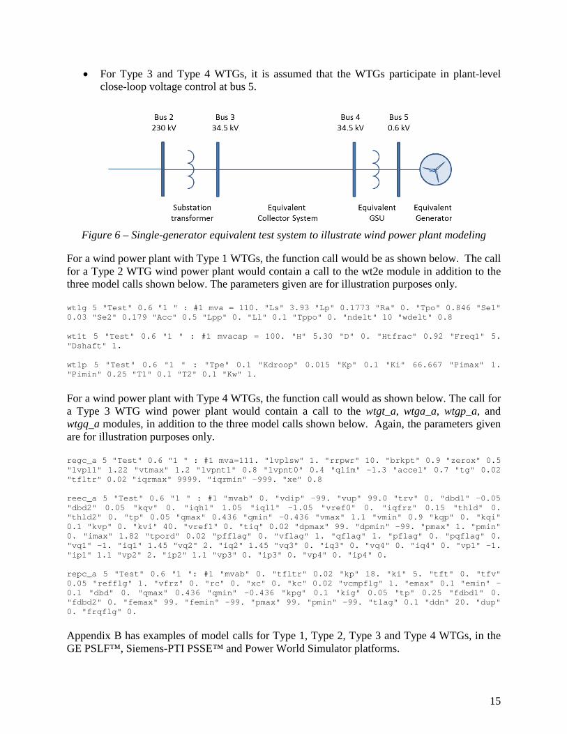
• For Type 3 and Type 4 WTGs, it is assumed that the WTGs participate in plant-level close-loop voltage control at bus 5.
Figure 6 – Single-generator equivalent test system to illustrate wind power plant modeling
For a wind power plant with Type 1 WTGs, the function call would be as shown below. The call for a Type 2 WTG wind power plant would contain a call to the wt2e module in addition to the three model calls shown below. The parameters given are for illustration purposes only. wt1g 5 "Test" 0.6 "1 " : #1 mva = 110. "Ls" 3.93 "Lp" 0.1773 "Ra" 0. "Tpo" 0.846 "Se1" 0.03 "Se2" 0.179 "Acc" 0.5 "Lpp" 0. "Ll" 0.1 "Tppo" 0. "ndelt" 10 "wdelt" 0.8 wt1t 5 "Test" 0.6 "1 " : #1 mvacap = 100. "H" 5.30 "D" 0. "Htfrac" 0.92 "Freq1" 5. "Dshaft" 1. wt1p 5 "Test" 0.6 "1 " : "Tpe" 0.1 "Kdroop" 0.015 "Kp" 0.1 "Ki" 66.667 "Pimax" 1. "Pimin" 0.25 "T1" 0.1 "T2" 0.1 "Kw" 1.
For a wind power plant with Type 4 WTGs, the function call would as shown below. The call for a Type 3 WTG wind power plant would contain a call to the wtgt_a, wtga_a, wtgp_a, and wtgq_a modules, in addition to the three model calls shown below. Again, the parameters given are for illustration purposes only. regc_a 5 "Test" 0.6 "1 " : #1 mva=111. "lvplsw" 1. "rrpwr" 10. "brkpt" 0.9 "zerox" 0.5 "lvpl1" 1.22 "vtmax" 1.2 "lvpnt1" 0.8 "lvpnt0" 0.4 "qlim" -1.3 "accel" 0.7 "tg" 0.02 "tfltr" 0.02 "iqrmax" 9999. "iqrmin" -999. "xe" 0.8 reec_a 5 "Test" 0.6 "1 " : #1 "mvab" 0. "vdip" -99. "vup" 99.0 "trv" 0. "dbd1" -0.05 "dbd2" 0.05 "kqv" 0. "iqh1" 1.05 "iql1" -1.05 "vref0" 0. "iqfrz" 0.15 "thld" 0. "thld2" 0. "tp" 0.05 "qmax" 0.436 "qmin" -0.436 "vmax" 1.1 "vmin" 0.9 "kqp" 0. "kqi" 0.1 "kvp" 0. "kvi" 40. "vref1" 0. "tiq" 0.02 "dpmax" 99. "dpmin" -99. "pmax" 1. "pmin" 0. "imax" 1.82 "tpord" 0.02 "pfflag" 0. "vflag" 1. "qflag" 1. "pflag" 0. "pqflag" 0. "vq1" -1. "iq1" 1.45 "vq2" 2. "iq2" 1.45 "vq3" 0. "iq3" 0. "vq4" 0. "iq4" 0. "vp1" -1. "ip1" 1.1 "vp2" 2. "ip2" 1.1 "vp3" 0. "ip3" 0. "vp4" 0. "ip4" 0. repc_a 5 "Test" 0.6 "1 ": #1 "mvab" 0. "tfltr" 0.02 "kp" 18. "ki" 5. "tft" 0. "tfv" 0.05 "refflg" 1. "vfrz" 0. "rc" 0. "xc" 0. "kc" 0.02 "vcmpflg" 1. "emax" 0.1 "emin" -0.1 "dbd" 0. "qmax" 0.436 "qmin" -0.436 "kpg" 0.1 "kig" 0.05 "tp" 0.25 "fdbd1" 0. "fdbd2" 0. "femax" 99. "femin" -99. "pmax" 99. "pmin" -99. "tlag" 0.1 "ddn" 20. "dup" 0. "frqflg" 0.
Appendix B has examples of model calls for Type 1, Type 2, Type 3 and Type 4 WTGs, in the GE PSLF™, Siemens-PTI PSSE™ and Power World Simulator platforms.
16
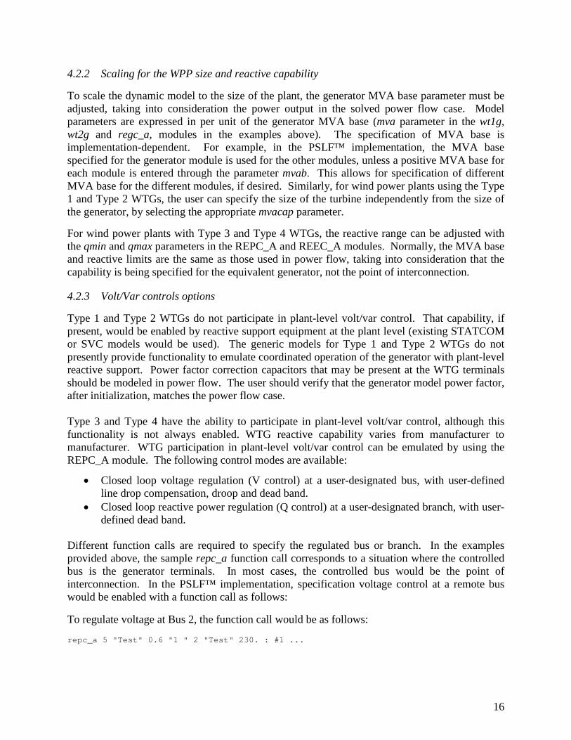
4.2.2 Scaling for the WPP size and reactive capability
To scale the dynamic model to the size of the plant, the generator MVA base parameter must be adjusted, taking into consideration the power output in the solved power flow case. Model parameters are expressed in per unit of the generator MVA base (mva parameter in the wt1g, wt2g and regc_a, modules in the examples above). The specification of MVA base is implementation-dependent. For example, in the PSLF™ implementation, the MVA base specified for the generator module is used for the other modules, unless a positive MVA base for each module is entered through the parameter mvab. This allows for specification of different MVA base for the different modules, if desired. Similarly, for wind power plants using the Type 1 and Type 2 WTGs, the user can specify the size of the turbine independently from the size of the generator, by selecting the appropriate mvacap parameter. For wind power plants with Type 3 and Type 4 WTGs, the reactive range can be adjusted with the qmin and qmax parameters in the REPC_A and REEC_A modules. Normally, the MVA base and reactive limits are the same as those used in power flow, taking into consideration that the capability is being specified for the equivalent generator, not the point of interconnection.
4.2.3 Volt/Var controls options
Type 1 and Type 2 WTGs do not participate in plant-level volt/var control. That capability, if present, would be enabled by reactive support equipment at the plant level (existing STATCOM or SVC models would be used). The generic models for Type 1 and Type 2 WTGs do not presently provide functionality to emulate coordinated operation of the generator with plant-level reactive support. Power factor correction capacitors that may be present at the WTG terminals should be modeled in power flow. The user should verify that the generator model power factor, after initialization, matches the power flow case. Type 3 and Type 4 have the ability to participate in plant-level volt/var control, although this functionality is not always enabled. WTG reactive capability varies from manufacturer to manufacturer. WTG participation in plant-level volt/var control can be emulated by using the REPC_A module. The following control modes are available:
• Closed loop voltage regulation (V control) at a user-designated bus, with user-defined line drop compensation, droop and dead band.
• Closed loop reactive power regulation (Q control) at a user-designated branch, with user-defined dead band.
Different function calls are required to specify the regulated bus or branch. In the examples provided above, the sample repc_a function call corresponds to a situation where the controlled bus is the generator terminals. In most cases, the controlled bus would be the point of interconnection. In the PSLF™ implementation, specification voltage control at a remote bus would be enabled with a function call as follows:
To regulate voltage at Bus 2, the function call would be as follows: repc_a 5 "Test" 0.6 "1 " 2 "Test" 230. : #1 ...
17
To regulate the point defined by bus (mon_i) + |rc + jxc|Ibranch, the function call would be as follows: repc_a 5 "Test" 0.6 "1 " ! ! ! ! ! 5 "WTG TERM" 0.6 4 "Test" 34.5 "1 " : #1 ...
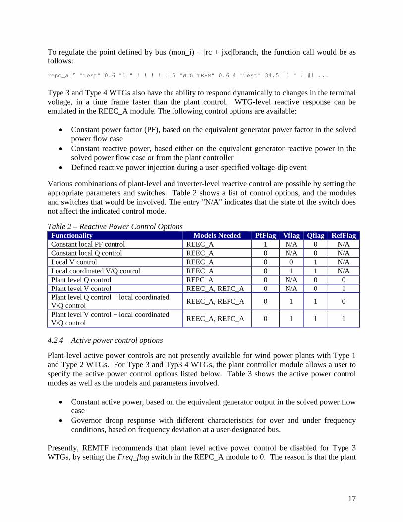
Type 3 and Type 4 WTGs also have the ability to respond dynamically to changes in the terminal voltage, in a time frame faster than the plant control. WTG-level reactive response can be emulated in the REEC_A module. The following control options are available:
• Constant power factor (PF), based on the equivalent generator power factor in the solved power flow case
• Constant reactive power, based either on the equivalent generator reactive power in the solved power flow case or from the plant controller
• Defined reactive power injection during a user-specified voltage-dip event Various combinations of plant-level and inverter-level reactive control are possible by setting the appropriate parameters and switches. Table 2 shows a list of control options, and the modules and switches that would be involved. The entry "N/A" indicates that the state of the switch does not affect the indicated control mode. Table 2 – Reactive Power Control Options Functionality Models Needed PfFlag Vflag Qflag RefFlag Constant local PF control REEC_A 1 N/A 0 N/A Constant local Q control REEC_A 0 N/A 0 N/A Local V control REEC_A 0 0 1 N/A Local coordinated V/Q control REEC_A 0 1 1 N/A Plant level Q control REPC_A 0 N/A 0 0 Plant level V control REEC_A, REPC_A 0 N/A 0 1 Plant level Q control + local coordinated V/Q control REEC_A, REPC_A 0 1 1 0
Plant level V control + local coordinated V/Q control REEC_A, REPC_A 0 1 1 1
4.2.4 Active power control options
Plant-level active power controls are not presently available for wind power plants with Type 1 and Type 2 WTGs. For Type 3 and Typ3 4 WTGs, the plant controller module allows a user to specify the active power control options listed below. Table 3 shows the active power control modes as well as the models and parameters involved.
• Constant active power, based on the equivalent generator output in the solved power flow case
• Governor droop response with different characteristics for over and under frequency conditions, based on frequency deviation at a user-designated bus.
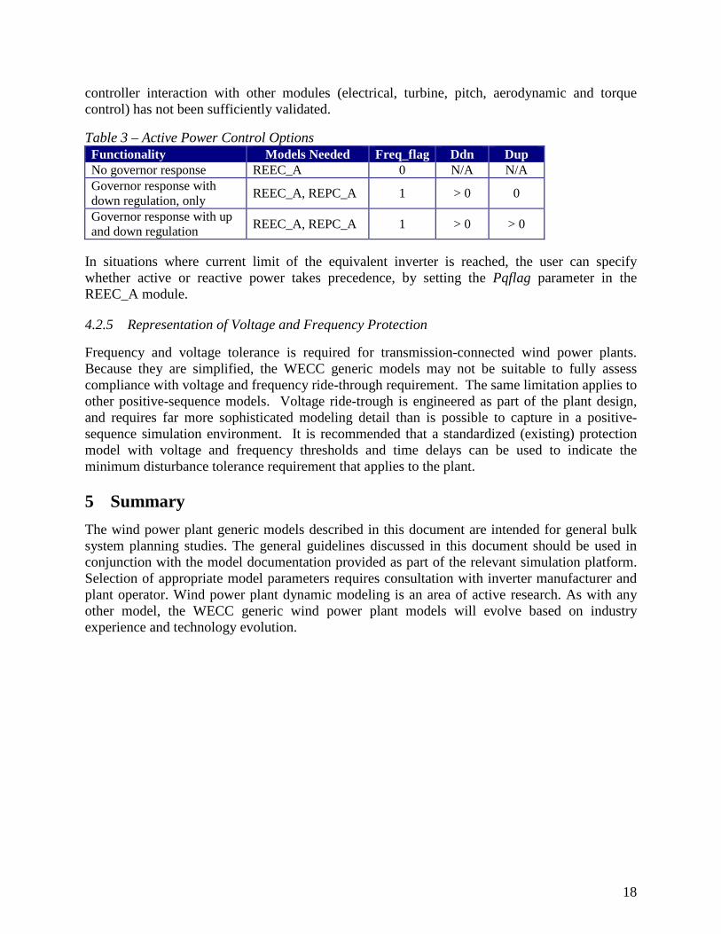
Presently, REMTF recommends that plant level active power control be disabled for Type 3 WTGs, by setting the Freq_flag switch in the REPC_A module to 0. The reason is that the plant
18
controller interaction with other modules (electrical, turbine, pitch, aerodynamic and torque control) has not been sufficiently validated. Table 3 – Active Power Control Options Functionality Models Needed Freq_flag Ddn Dup No governor response REEC_A 0 N/A N/A Governor response with down regulation, only REEC_A, REPC_A 1 > 0 0
Governor response with up and down regulation REEC_A, REPC_A 1 > 0 > 0
In situations where current limit of the equivalent inverter is reached, the user can specify whether active or reactive power takes precedence, by setting the Pqflag parameter in the REEC_A module.
4.2.5 Representation of Voltage and Frequency Protection
Frequency and voltage tolerance is required for transmission-connected wind power plants. Because they are simplified, the WECC generic models may not be suitable to fully assess compliance with voltage and frequency ride-through requirement. The same limitation applies to other positive-sequence models. Voltage ride-trough is engineered as part of the plant design, and requires far more sophisticated modeling detail than is possible to capture in a positive-sequence simulation environment. It is recommended that a standardized (existing) protection model with voltage and frequency thresholds and time delays can be used to indicate the minimum disturbance tolerance requirement that applies to the plant. 5 Summary The wind power plant generic models described in this document are intended for general bulk system planning studies. The general guidelines discussed in this document should be used in conjunction with the model documentation provided as part of the relevant simulation platform. Selection of appropriate model parameters requires consultation with inverter manufacturer and plant operator. Wind power plant dynamic modeling is an area of active research. As with any other model, the WECC generic wind power plant models will evolve based on industry experience and technology evolution.
19
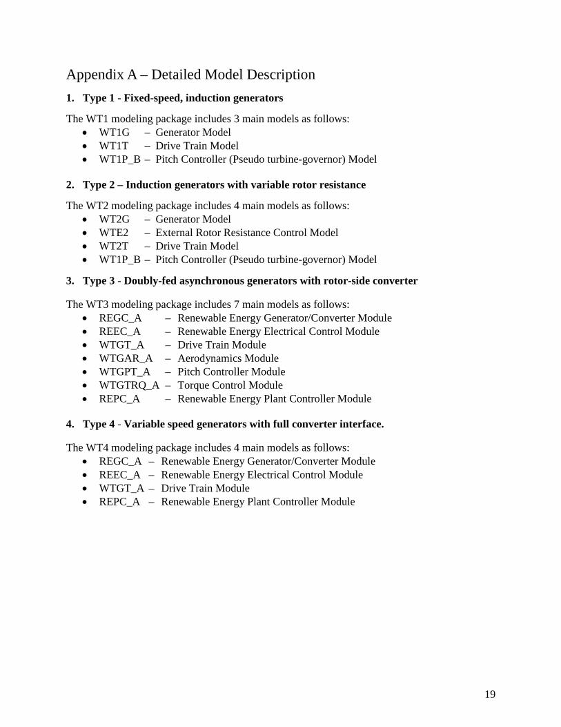
Appendix A – Detailed Model Description 1. Type 1 - Fixed-speed, induction generators The WT1 modeling package includes 3 main models as follows:
• WT1G – Generator Model • WT1T – Drive Train Model • WT1P_B – Pitch Controller (Pseudo turbine-governor) Model
2. Type 2 – Induction generators with variable rotor resistance The WT2 modeling package includes 4 main models as follows:
• WT2G – Generator Model • WTE2 – External Rotor Resistance Control Model • WT2T – Drive Train Model • WT1P_B – Pitch Controller (Pseudo turbine-governor) Model
3. Type 3 - Doubly-fed asynchronous generators with rotor-side converter
The WT3 modeling package includes 7 main models as follows: • REGC_A – Renewable Energy Generator/Converter Module • REEC_A – Renewable Energy Electrical Control Module • WTGT_A – Drive Train Module • WTGAR_A – Aerodynamics Module • WTGPT_A – Pitch Controller Module • WTGTRQ_A – Torque Control Module • REPC_A – Renewable Energy Plant Controller Module
4. Type 4 - Variable speed generators with full converter interface.
The WT4 modeling package includes 4 main models as follows: • REGC_A – Renewable Energy Generator/Converter Module • REEC_A – Renewable Energy Electrical Control Module • WTGT_A – Drive Train Module • REPC_A – Renewable Energy Plant Controller Module
20
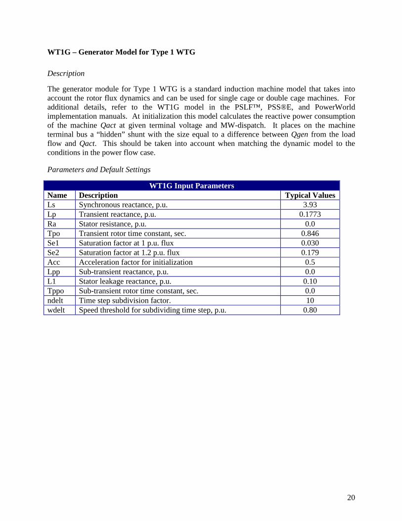
WT1G – Generator Model for Type 1 WTG
Description
The generator module for Type 1 WTG is a standard induction machine model that takes into account the rotor flux dynamics and can be used for single cage or double cage machines. For additional details, refer to the WT1G model in the PSLF™, PSS®E, and PowerWorld implementation manuals. At initialization this model calculates the reactive power consumption of the machine Qact at given terminal voltage and MW-dispatch. It places on the machine terminal bus a “hidden” shunt with the size equal to a difference between Qgen from the load flow and Qact. This should be taken into account when matching the dynamic model to the conditions in the power flow case.
Parameters and Default Settings
WT1G Input Parameters Name Description Typical Values Ls Synchronous reactance, p.u. 3.93 Lp Transient reactance, p.u. 0.1773 Ra Stator resistance, p.u. 0.0 Tpo Transient rotor time constant, sec. 0.846 Se1 Saturation factor at 1 p.u. flux 0.030 Se2 Saturation factor at 1.2 p.u. flux 0.179 Acc Acceleration factor for initialization 0.5 Lpp Sub-transient reactance, p.u. 0.0 L1 Stator leakage reactance, p.u. 0.10 Tppo Sub-transient rotor time constant, sec. 0.0 ndelt Time step subdivision factor. 10 wdelt Speed threshold for subdividing time step, p.u. 0.80
21
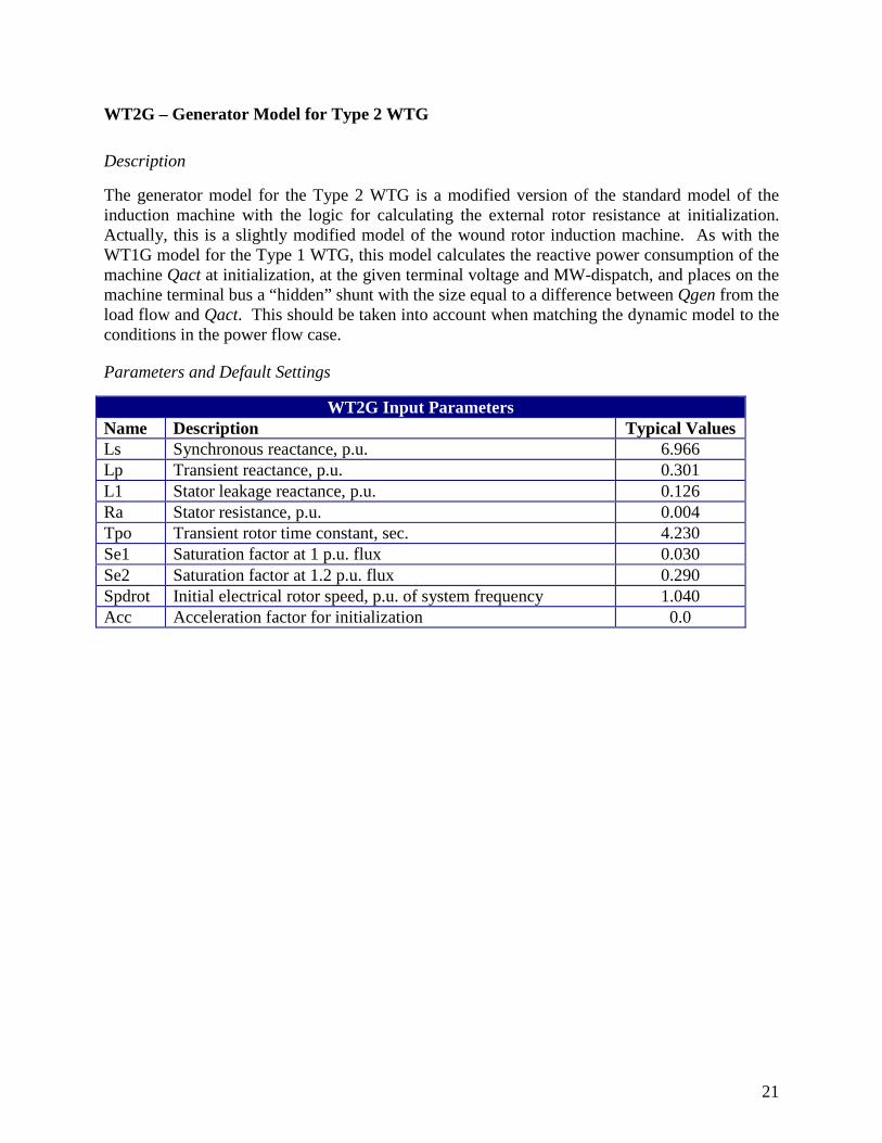
WT2G – Generator Model for Type 2 WTG
Description
The generator model for the Type 2 WTG is a modified version of the standard model of the induction machine with the logic for calculating the external rotor resistance at initialization. Actually, this is a slightly modified model of the wound rotor induction machine. As with the WT1G model for the Type 1 WTG, this model calculates the reactive power consumption of the machine Qact at initialization, at the given terminal voltage and MW-dispatch, and places on the machine terminal bus a “hidden” shunt with the size equal to a difference between Qgen from the load flow and Qact. This should be taken into account when matching the dynamic model to the conditions in the power flow case.
Parameters and Default Settings
WT2G Input Parameters Name Description Typical Values Ls Synchronous reactance, p.u. 6.966 Lp Transient reactance, p.u. 0.301 L1 Stator leakage reactance, p.u. 0.126 Ra Stator resistance, p.u. 0.004 Tpo Transient rotor time constant, sec. 4.230 Se1 Saturation factor at 1 p.u. flux 0.030 Se2 Saturation factor at 1.2 p.u. flux 0.290 Spdrot Initial electrical rotor speed, p.u. of system frequency 1.040 Acc Acceleration factor for initialization 0.0
22
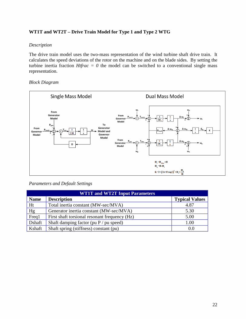
WT1T and WT2T – Drive Train Model for Type 1 and Type 2 WTG
Description
The drive train model uses the two-mass representation of the wind turbine shaft drive train. It calculates the speed deviations of the rotor on the machine and on the blade sides. By setting the turbine inertia fraction Htfrac = 0 the model can be switched to a conventional single mass representation. Block Diagram
Parameters and Default Settings
WT1T and WT2T Input Parameters Name Description Typical Values Ht Total inertia constant (MW-sec/MVA) 4.87 Hg Generator inertia constant (MW-sec/MVA) 5.30 Freq1 First shaft torsional resonant frequency (Hz) 5.00 Dshaft Shaft damping factor (pu P / pu speed) 1.00 Kshaft Shaft spring (stiffness) constant (pu) 0.0
23
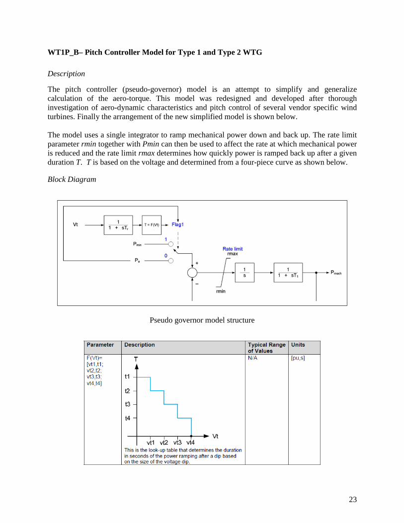
WT1P_B– Pitch Controller Model for Type 1 and Type 2 WTG
Description
The pitch controller (pseudo-governor) model is an attempt to simplify and generalize calculation of the aero-torque. This model was redesigned and developed after thorough investigation of aero-dynamic characteristics and pitch control of several vendor specific wind turbines. Finally the arrangement of the new simplified model is shown below. The model uses a single integrator to ramp mechanical power down and back up. The rate limit parameter rmin together with Pmin can then be used to affect the rate at which mechanical power is reduced and the rate limit rmax determines how quickly power is ramped back up after a given duration T. T is based on the voltage and determined from a four-piece curve as shown below.
Block Diagram
Pseudo governor model structure
24
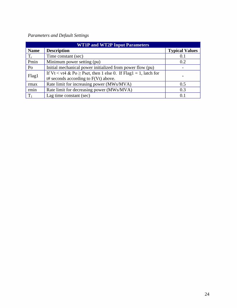
Parameters and Default Settings
WT1P and WT2P Input Parameters Name Description Typical Values Tr Time constant (sec) 0.1 Pmin Minimum power setting (pu) 0.2 Po Initial mechanical power initialized from power flow (pu) -
Flag1 If Vt < vt4 & Po ≥ Pset, then 1 else 0. If Flag1 = 1, latch for t# seconds according to F(Vt) above. -
rmax Rate limit for increasing power (MWs/MVA) 0.5 rmin Rate limit for decreasing power (MWs/MVA) 0.3 T1 Lag time constant (sec) 0.1
25
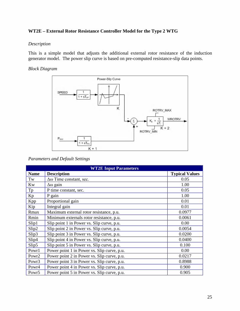
WT2E – External Rotor Resistance Controller Model for the Type 2 WTG
Description
This is a simple model that adjusts the additional external rotor resistance of the induction generator model. The power slip curve is based on pre-computed resistance-slip data points.
Block Diagram
Parameters and Default Settings
WT2E Input Parameters Name Description Typical Values Tw Δω Time constant, sec. 0.05 Kw Δω gain 1.00 Tp P time constant, sec. 0.05 Kp P gain 1.00 Kpp Proportional gain 0.01 Kip Integral gain 0.01 Rmax Maximum external rotor resistance, p.u. 0.0977 Rmin Minimum externals rotor resistance, p.u. 0.0061 Slip1 Slip point 1 in Power vs. Slip curve, p.u. 0.00 Slip2 Slip point 2 in Power vs. Slip curve, p.u. 0.0054 Slip3 Slip point 3 in Power vs. Slip curve, p.u. 0.0200 Slip4 Slip point 4 in Power vs. Slip curve, p.u. 0.0400 Slip5 Slip point 5 in Power vs. Slip curve, p.u. 0.100 Powr1 Power point 1 in Power vs. Slip curve, p.u. 0.00 Powr2 Power point 2 in Power vs. Slip curve, p.u. 0.0217 Powr3 Power point 3 in Power vs. Slip curve, p.u. 0.8988 Powr4 Power point 4 in Power vs. Slip curve, p.u. 0.900 Powr5 Power point 5 in Power vs. Slip curve, p.u. 0.905
26
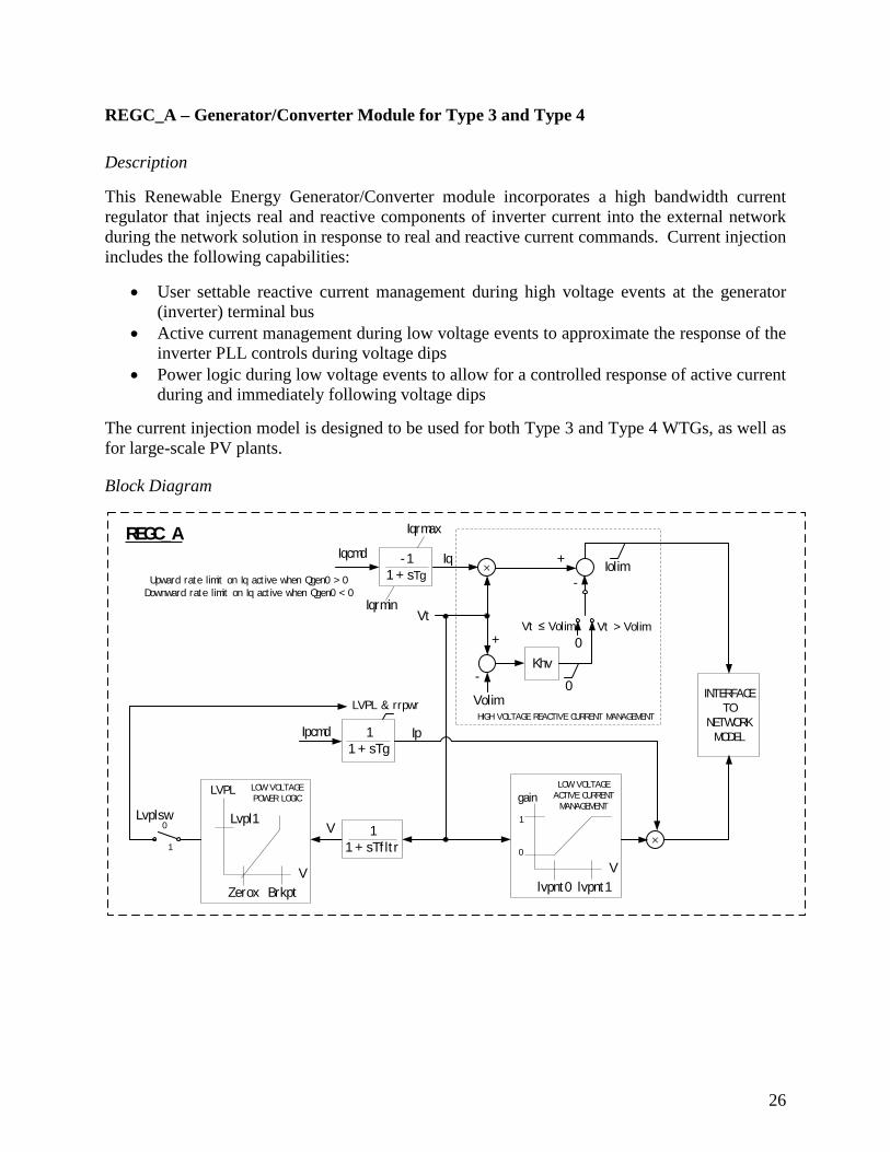
REGC_A – Generator/Converter Module for Type 3 and Type 4
Description
This Renewable Energy Generator/Converter module incorporates a high bandwidth current regulator that injects real and reactive components of inverter current into the external network during the network solution in response to real and reactive current commands. Current injection includes the following capabilities:
• User settable reactive current management during high voltage events at the generator (inverter) terminal bus
• Active current management during low voltage events to approximate the response of the inverter PLL controls during voltage dips
• Power logic during low voltage events to allow for a controlled response of active current during and immediately following voltage dips
The current injection model is designed to be used for both Type 3 and Type 4 WTGs, as well as for large-scale PV plants.
Block Diagram
REGC_A
Ipcmd 11 + sTg
LVPL & rrpwr
lvpnt0 lvpnt1
gain
V
1
0×
Ip
INTERFACE TO
NETWORK MODEL
LOW VOLTAGE ACTIVE CURRENT
MANAGEMENT
Iqcmd -11 + sTg
Iq×
Volim
-Khv
0
0
Vt ≤ Volim Vt > Volim
HIGH VOLTAGE REACTIVE CURRENT MANAGEMENT
Iolim
Vt
-
V
Zerox Brkpt
Lvpl1
LVPL
V
LOW VOLTAGE POWER LOGIC
0
1
Lvplsw1
1 + sTf lt r
Iqrmin
Iqrmax
+
+Upward rate limit on Iq act ive when Qgen0 > 0
Downward rate limit on Iq act ive when Qgen0 < 0
27
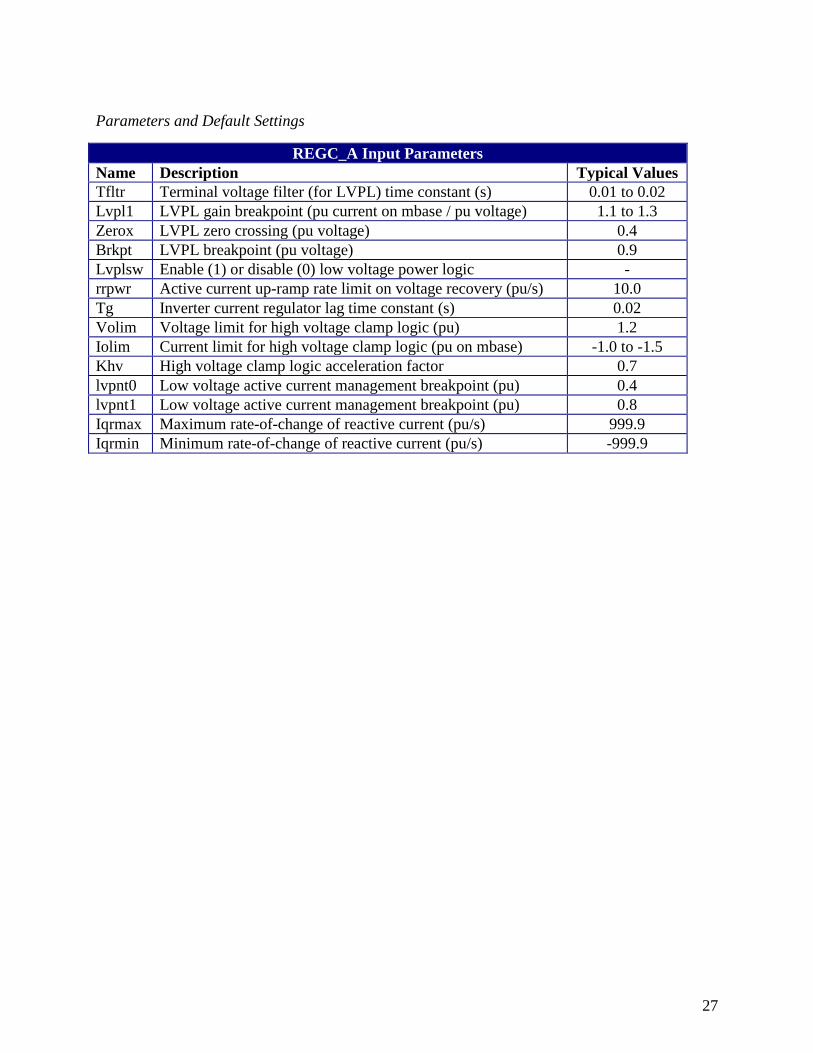
Parameters and Default Settings
REGC_A Input Parameters Name Description Typical Values Tfltr Terminal voltage filter (for LVPL) time constant (s) 0.01 to 0.02 Lvpl1 LVPL gain breakpoint (pu current on mbase / pu voltage) 1.1 to 1.3 Zerox LVPL zero crossing (pu voltage) 0.4 Brkpt LVPL breakpoint (pu voltage) 0.9 Lvplsw Enable (1) or disable (0) low voltage power logic - rrpwr Active current up-ramp rate limit on voltage recovery (pu/s) 10.0 Tg Inverter current regulator lag time constant (s) 0.02 Volim Voltage limit for high voltage clamp logic (pu) 1.2 Iolim Current limit for high voltage clamp logic (pu on mbase) -1.0 to -1.5 Khv High voltage clamp logic acceleration factor 0.7 lvpnt0 Low voltage active current management breakpoint (pu) 0.4 lvpnt1 Low voltage active current management breakpoint (pu) 0.8 Iqrmax Maximum rate-of-change of reactive current (pu/s) 999.9 Iqrmin Minimum rate-of-change of reactive current (pu/s) -999.9
28
REEC_A – Electrical Control Module for Type 3 and Type 4 WTG
Description
This Renewable Energy Electrical Control module emulates the active and reactive power controls implemented in the WTG converter. It provides options for active power control, including constant power factor initialized from power flow, and reactive power reference through the Qext input. Two PI loops are provided to represent the reactive control and local voltage response. These local controls can be bypassed by using the switches VFlag and QFlag, if desired. The model allows for specification of a prescribed reactive control response during a voltage dip scenario. When the voltage dip condition is detected, the state of the active and reactive power PI controllers is frozen, and the reactive current injection iqinj is according to the operation of the dynamic switch SW. Equipment manufacturers must be consulted to enable these options. This model also provides for current limiting. For more information on the current limiting logic please refer to the WECC Second Generation Wind Turbine Models14
Block Diagram
14 http://www.wecc.biz/library/WECC%20Documents/Documents%20for%20Generators/WECC%20Second%20Generation%20Wind%20Turbine%20Models%20012314.pdf
29
Parameters and sample settings
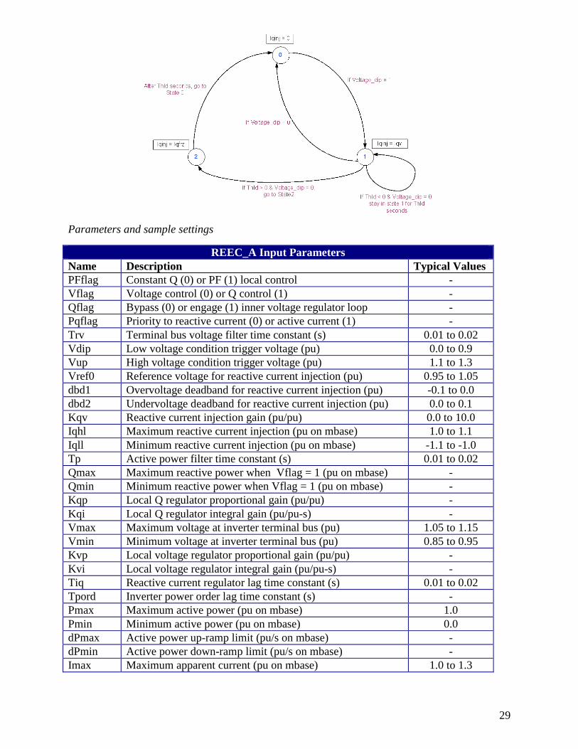
REEC_A Input Parameters Name Description Typical Values PFflag Constant Q (0) or PF (1) local control - Vflag Voltage control (0) or Q control (1) - Qflag Bypass (0) or engage (1) inner voltage regulator loop - Pqflag Priority to reactive current (0) or active current (1) - Trv Terminal bus voltage filter time constant (s) 0.01 to 0.02 Vdip Low voltage condition trigger voltage (pu) 0.0 to 0.9 Vup High voltage condition trigger voltage (pu) 1.1 to 1.3 Vref0 Reference voltage for reactive current injection (pu) 0.95 to 1.05 dbd1 Overvoltage deadband for reactive current injection (pu) -0.1 to 0.0 dbd2 Undervoltage deadband for reactive current injection (pu) 0.0 to 0.1 Kqv Reactive current injection gain (pu/pu) 0.0 to 10.0 Iqhl Maximum reactive current injection (pu on mbase) 1.0 to 1.1 Iqll Minimum reactive current injection (pu on mbase) -1.1 to -1.0 Tp Active power filter time constant (s) 0.01 to 0.02 Qmax Maximum reactive power when Vflag = 1 (pu on mbase) - Qmin Minimum reactive power when Vflag = 1 (pu on mbase) - Kqp Local Q regulator proportional gain (pu/pu) - Kqi Local Q regulator integral gain (pu/pu-s) - Vmax Maximum voltage at inverter terminal bus (pu) 1.05 to 1.15 Vmin Minimum voltage at inverter terminal bus (pu) 0.85 to 0.95 Kvp Local voltage regulator proportional gain (pu/pu) - Kvi Local voltage regulator integral gain (pu/pu-s) - Tiq Reactive current regulator lag time constant (s) 0.01 to 0.02 Tpord Inverter power order lag time constant (s) - Pmax Maximum active power (pu on mbase) 1.0 Pmin Minimum active power (pu on mbase) 0.0 dPmax Active power up-ramp limit (pu/s on mbase) - dPmin Active power down-ramp limit (pu/s on mbase) - Imax Maximum apparent current (pu on mbase) 1.0 to 1.3
30
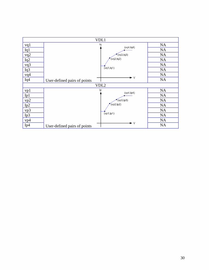
VDL1
vq1
User-defined pairs of points
NA Iq1 NA vq2 NA Iq2 NA vq3 NA Iq3 NA vq4 NA Iq4 NA
VDL2 vp1
User-defined pairs of points
NA Ip1 NA vp2 NA Ip2 NA vp3 NA Ip3 NA vp4 NA Ip4 NA
31
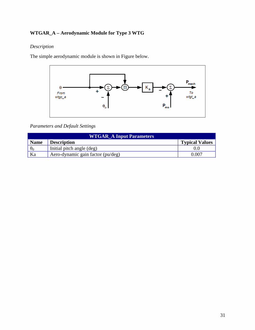
WTGAR_A – Aerodynamic Module for Type 3 WTG
Description
The simple aerodynamic module is shown in Figure below.
Parameters and Default Settings
WTGAR_A Input Parameters Name Description Typical Values θ0 Initial pitch angle (deg) 0.0 Ka Aero-dynamic gain factor (pu/deg) 0.007
32
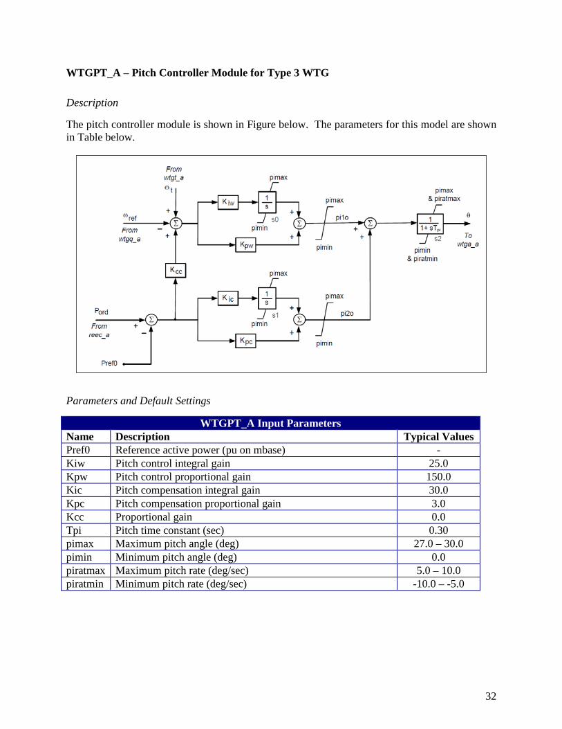
WTGPT_A – Pitch Controller Module for Type 3 WTG
Description
The pitch controller module is shown in Figure below. The parameters for this model are shown in Table below.
Parameters and Default Settings
WTGPT_A Input Parameters Name Description Typical Values Pref0 Reference active power (pu on mbase) - Kiw Pitch control integral gain 25.0 Kpw Pitch control proportional gain 150.0 Kic Pitch compensation integral gain 30.0 Kpc Pitch compensation proportional gain 3.0 Kcc Proportional gain 0.0 Tpi Pitch time constant (sec) 0.30 pimax Maximum pitch angle (deg) 27.0 – 30.0 pimin Minimum pitch angle (deg) 0.0 piratmax Maximum pitch rate (deg/sec) 5.0 – 10.0 piratmin Minimum pitch rate (deg/sec) -10.0 – -5.0
33
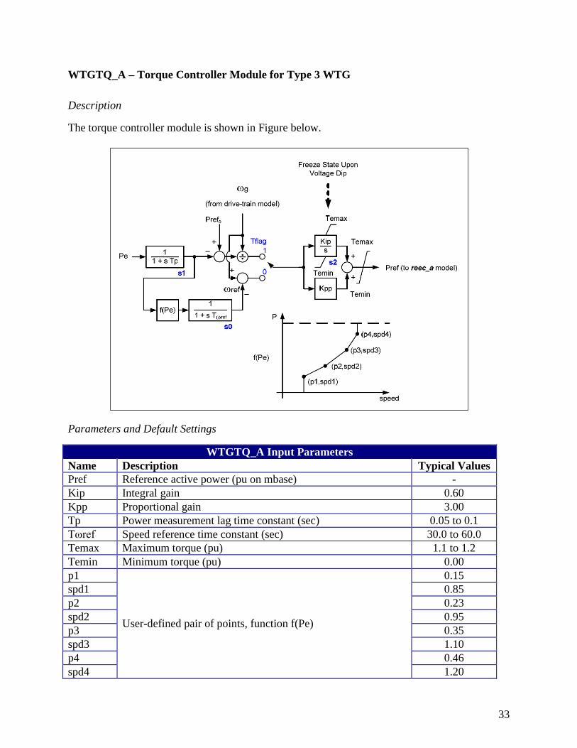
WTGTQ_A – Torque Controller Module for Type 3 WTG
Description
The torque controller module is shown in Figure below.
Parameters and Default Settings
WTGTQ_A Input Parameters Name Description Typical Values Pref Reference active power (pu on mbase) - Kip Integral gain 0.60 Kpp Proportional gain 3.00 Tp Power measurement lag time constant (sec) 0.05 to 0.1 Tωref Speed reference time constant (sec) 30.0 to 60.0 Temax Maximum torque (pu) 1.1 to 1.2 Temin Minimum torque (pu) 0.00 p1
User-defined pair of points, function f(Pe)
0.15 spd1 0.85 p2 0.23 spd2 0.95 p3 0.35 spd3 1.10 p4 0.46 spd4 1.20
34
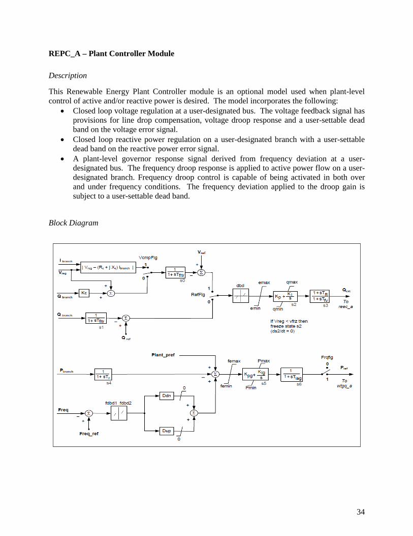
REPC_A – Plant Controller Module
Description
This Renewable Energy Plant Controller module is an optional model used when plant-level control of active and/or reactive power is desired. The model incorporates the following:
• Closed loop voltage regulation at a user-designated bus. The voltage feedback signal has provisions for line drop compensation, voltage droop response and a user-settable dead band on the voltage error signal.
• Closed loop reactive power regulation on a user-designated branch with a user-settable dead band on the reactive power error signal.
• A plant-level governor response signal derived from frequency deviation at a user-designated bus. The frequency droop response is applied to active power flow on a user-designated branch. Frequency droop control is capable of being activated in both over and under frequency conditions. The frequency deviation applied to the droop gain is subject to a user-settable dead band.
Block Diagram
35
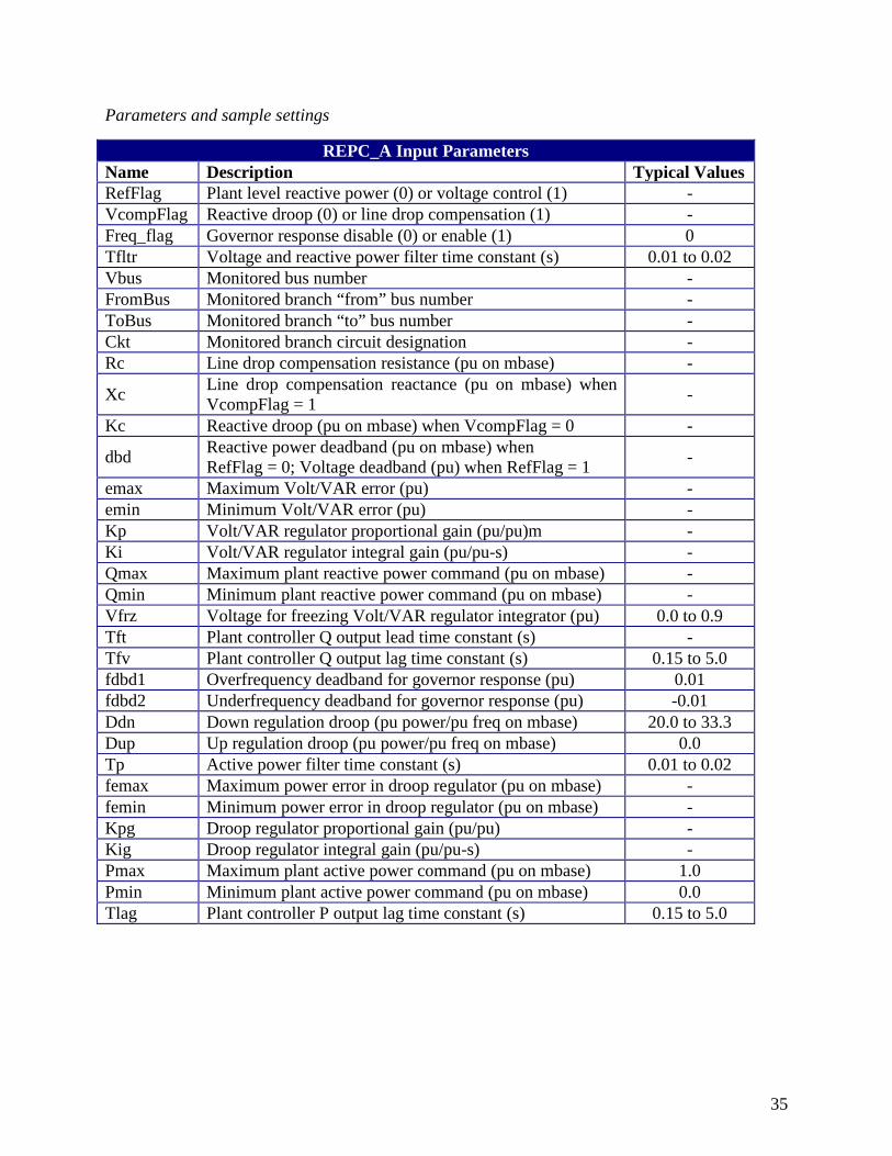
Parameters and sample settings
REPC_A Input Parameters Name Description Typical Values RefFlag Plant level reactive power (0) or voltage control (1) - VcompFlag Reactive droop (0) or line drop compensation (1) - Freq_flag Governor response disable (0) or enable (1) 0 Tfltr Voltage and reactive power filter time constant (s) 0.01 to 0.02 Vbus Monitored bus number - FromBus Monitored branch “from” bus number - ToBus Monitored branch “to” bus number - Ckt Monitored branch circuit designation - Rc Line drop compensation resistance (pu on mbase) -
Xc Line drop compensation reactance (pu on mbase) when VcompFlag = 1 -
Kc Reactive droop (pu on mbase) when VcompFlag = 0 -
dbd Reactive power deadband (pu on mbase) when RefFlag = 0; Voltage deadband (pu) when RefFlag = 1 -
emax Maximum Volt/VAR error (pu) - emin Minimum Volt/VAR error (pu) - Kp Volt/VAR regulator proportional gain (pu/pu)m - Ki Volt/VAR regulator integral gain (pu/pu-s) - Qmax Maximum plant reactive power command (pu on mbase) - Qmin Minimum plant reactive power command (pu on mbase) - Vfrz Voltage for freezing Volt/VAR regulator integrator (pu) 0.0 to 0.9 Tft Plant controller Q output lead time constant (s) - Tfv Plant controller Q output lag time constant (s) 0.15 to 5.0 fdbd1 Overfrequency deadband for governor response (pu) 0.01 fdbd2 Underfrequency deadband for governor response (pu) -0.01 Ddn Down regulation droop (pu power/pu freq on mbase) 20.0 to 33.3 Dup Up regulation droop (pu power/pu freq on mbase) 0.0 Tp Active power filter time constant (s) 0.01 to 0.02 femax Maximum power error in droop regulator (pu on mbase) - femin Minimum power error in droop regulator (pu on mbase) - Kpg Droop regulator proportional gain (pu/pu) - Kig Droop regulator integral gain (pu/pu-s) - Pmax Maximum plant active power command (pu on mbase) 1.0 Pmin Minimum plant active power command (pu on mbase) 0.0 Tlag Plant controller P output lag time constant (s) 0.15 to 5.0
36
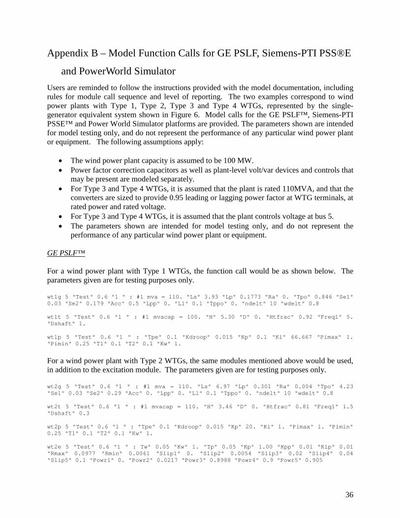
Appendix B – Model Function Calls for GE PSLF, Siemens-PTI PSS®E
and PowerWorld Simulator Users are reminded to follow the instructions provided with the model documentation, including rules for module call sequence and level of reporting. The two examples correspond to wind power plants with Type 1, Type 2, Type 3 and Type 4 WTGs, represented by the single-generator equivalent system shown in Figure 6. Model calls for the GE PSLF™, Siemens-PTI PSSE™ and Power World Simulator platforms are provided. The parameters shown are intended for model testing only, and do not represent the performance of any particular wind power plant or equipment. The following assumptions apply:
• The wind power plant capacity is assumed to be 100 MW. • Power factor correction capacitors as well as plant-level volt/var devices and controls that
may be present are modeled separately. • For Type 3 and Type 4 WTGs, it is assumed that the plant is rated 110MVA, and that the
converters are sized to provide 0.95 leading or lagging power factor at WTG terminals, at rated power and rated voltage.
• For Type 3 and Type 4 WTGs, it is assumed that the plant controls voltage at bus 5. • The parameters shown are intended for model testing only, and do not represent the
performance of any particular wind power plant or equipment. GE PSLF™ For a wind power plant with Type 1 WTGs, the function call would be as shown below. The parameters given are for testing purposes only. wt1g 5 "Test" 0.6 "1 " : #1 mva = 110. "Ls" 3.93 "Lp" 0.1773 "Ra" 0. "Tpo" 0.846 "Se1" 0.03 "Se2" 0.179 "Acc" 0.5 "Lpp" 0. "Ll" 0.1 "Tppo" 0. "ndelt" 10 "wdelt" 0.8 wt1t 5 "Test" 0.6 "1 " : #1 mvacap = 100. "H" 5.30 "D" 0. "Htfrac" 0.92 "Freq1" 5. "Dshaft" 1. wt1p 5 "Test" 0.6 "1 " : "Tpe" 0.1 "Kdroop" 0.015 "Kp" 0.1 "Ki" 66.667 "Pimax" 1. "Pimin" 0.25 "T1" 0.1 "T2" 0.1 "Kw" 1.
For a wind power plant with Type 2 WTGs, the same modules mentioned above would be used, in addition to the excitation module. The parameters given are for testing purposes only. wt2g 5 "Test" 0.6 "1 " : #1 mva = 110. "Ls" 6.97 "Lp" 0.301 "Ra" 0.004 "Tpo" 4.23 "Se1" 0.03 "Se2" 0.29 "Acc" 0. "Lpp" 0. "Ll" 0.1 "Tppo" 0. "ndelt" 10 "wdelt" 0.8 wt2t 5 "Test" 0.6 "1 " : #1 mvacap = 110. "H" 3.46 "D" 0. "Htfrac" 0.81 "Freq1" 1.5 "Dshaft" 0.3 wt2p 5 "Test" 0.6 "1 " : "Tpe" 0.1 "Kdroop" 0.015 "Kp" 20. "Ki" 1. "Pimax" 1. "Pimin" 0.25 "T1" 0.1 "T2" 0.1 "Kw" 1. wt2e 5 "Test" 0.6 "1 " : Tw" 0.05 "Kw" 1. "Tp" 0.05 "Kp" 1.00 "Kpp" 0.01 "Kip" 0.01 "Rmax" 0.0977 "Rmin" 0.0061 "Slip1" 0. "Slip2" 0.0054 "Slip3" 0.02 "Slip4" 0.04 "Slip5" 0.1 "Powr1" 0. "Powr2" 0.0217 "Powr3" 0.8988 "Powr4" 0.9 "Powr5" 0.905
37
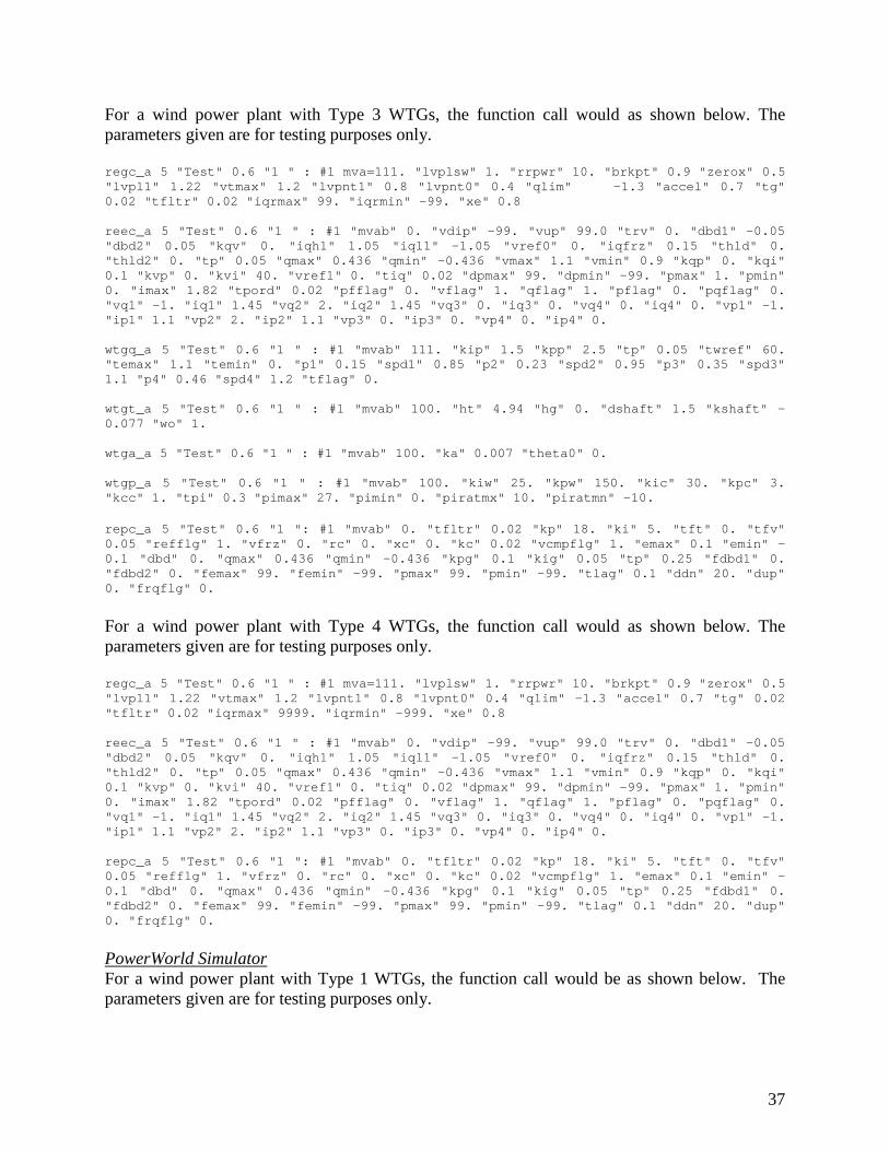
For a wind power plant with Type 3 WTGs, the function call would as shown below. The parameters given are for testing purposes only. regc_a 5 "Test" 0.6 "1 " : #1 mva=111. "lvplsw" 1. "rrpwr" 10. "brkpt" 0.9 "zerox" 0.5 "lvpl1" 1.22 "vtmax" 1.2 "lvpnt1" 0.8 "lvpnt0" 0.4 "qlim" -1.3 "accel" 0.7 "tg" 0.02 "tfltr" 0.02 "iqrmax" 99. "iqrmin" -99. "xe" 0.8 reec_a 5 "Test" 0.6 "1 " : #1 "mvab" 0. "vdip" -99. "vup" 99.0 "trv" 0. "dbd1" -0.05 "dbd2" 0.05 "kqv" 0. "iqh1" 1.05 "iql1" -1.05 "vref0" 0. "iqfrz" 0.15 "thld" 0. "thld2" 0. "tp" 0.05 "qmax" 0.436 "qmin" -0.436 "vmax" 1.1 "vmin" 0.9 "kqp" 0. "kqi" 0.1 "kvp" 0. "kvi" 40. "vref1" 0. "tiq" 0.02 "dpmax" 99. "dpmin" -99. "pmax" 1. "pmin" 0. "imax" 1.82 "tpord" 0.02 "pfflag" 0. "vflag" 1. "qflag" 1. "pflag" 0. "pqflag" 0. "vq1" -1. "iq1" 1.45 "vq2" 2. "iq2" 1.45 "vq3" 0. "iq3" 0. "vq4" 0. "iq4" 0. "vp1" -1. "ip1" 1.1 "vp2" 2. "ip2" 1.1 "vp3" 0. "ip3" 0. "vp4" 0. "ip4" 0. wtgq_a 5 "Test" 0.6 "1 " : #1 "mvab" 111. "kip" 1.5 "kpp" 2.5 "tp" 0.05 "twref" 60. "temax" 1.1 "temin" 0. "p1" 0.15 "spd1" 0.85 "p2" 0.23 "spd2" 0.95 "p3" 0.35 "spd3" 1.1 "p4" 0.46 "spd4" 1.2 "tflag" 0. wtgt_a 5 "Test" 0.6 "1 " : #1 "mvab" 100. "ht" 4.94 "hg" 0. "dshaft" 1.5 "kshaft" -0.077 "wo" 1. wtga_a 5 "Test" 0.6 "1 " : #1 "mvab" 100. "ka" 0.007 "theta0" 0. wtgp_a 5 "Test" 0.6 "1 " : #1 "mvab" 100. "kiw" 25. "kpw" 150. "kic" 30. "kpc" 3. "kcc" 1. "tpi" 0.3 "pimax" 27. "pimin" 0. "piratmx" 10. "piratmn" -10. repc_a 5 "Test" 0.6 "1 ": #1 "mvab" 0. "tfltr" 0.02 "kp" 18. "ki" 5. "tft" 0. "tfv" 0.05 "refflg" 1. "vfrz" 0. "rc" 0. "xc" 0. "kc" 0.02 "vcmpflg" 1. "emax" 0.1 "emin" -0.1 "dbd" 0. "qmax" 0.436 "qmin" -0.436 "kpg" 0.1 "kig" 0.05 "tp" 0.25 "fdbd1" 0. "fdbd2" 0. "femax" 99. "femin" -99. "pmax" 99. "pmin" -99. "tlag" 0.1 "ddn" 20. "dup" 0. "frqflg" 0.
For a wind power plant with Type 4 WTGs, the function call would as shown below. The parameters given are for testing purposes only. regc_a 5 "Test" 0.6 "1 " : #1 mva=111. "lvplsw" 1. "rrpwr" 10. "brkpt" 0.9 "zerox" 0.5 "lvpl1" 1.22 "vtmax" 1.2 "lvpnt1" 0.8 "lvpnt0" 0.4 "qlim" -1.3 "accel" 0.7 "tg" 0.02 "tfltr" 0.02 "iqrmax" 9999. "iqrmin" -999. "xe" 0.8 reec_a 5 "Test" 0.6 "1 " : #1 "mvab" 0. "vdip" -99. "vup" 99.0 "trv" 0. "dbd1" -0.05 "dbd2" 0.05 "kqv" 0. "iqh1" 1.05 "iql1" -1.05 "vref0" 0. "iqfrz" 0.15 "thld" 0. "thld2" 0. "tp" 0.05 "qmax" 0.436 "qmin" -0.436 "vmax" 1.1 "vmin" 0.9 "kqp" 0. "kqi" 0.1 "kvp" 0. "kvi" 40. "vref1" 0. "tiq" 0.02 "dpmax" 99. "dpmin" -99. "pmax" 1. "pmin" 0. "imax" 1.82 "tpord" 0.02 "pfflag" 0. "vflag" 1. "qflag" 1. "pflag" 0. "pqflag" 0. "vq1" -1. "iq1" 1.45 "vq2" 2. "iq2" 1.45 "vq3" 0. "iq3" 0. "vq4" 0. "iq4" 0. "vp1" -1. "ip1" 1.1 "vp2" 2. "ip2" 1.1 "vp3" 0. "ip3" 0. "vp4" 0. "ip4" 0. repc_a 5 "Test" 0.6 "1 ": #1 "mvab" 0. "tfltr" 0.02 "kp" 18. "ki" 5. "tft" 0. "tfv" 0.05 "refflg" 1. "vfrz" 0. "rc" 0. "xc" 0. "kc" 0.02 "vcmpflg" 1. "emax" 0.1 "emin" -0.1 "dbd" 0. "qmax" 0.436 "qmin" -0.436 "kpg" 0.1 "kig" 0.05 "tp" 0.25 "fdbd1" 0. "fdbd2" 0. "femax" 99. "femin" -99. "pmax" 99. "pmin" -99. "tlag" 0.1 "ddn" 20. "dup" 0. "frqflg" 0.
PowerWorld Simulator For a wind power plant with Type 1 WTGs, the function call would be as shown below. The parameters given are for testing purposes only.
38
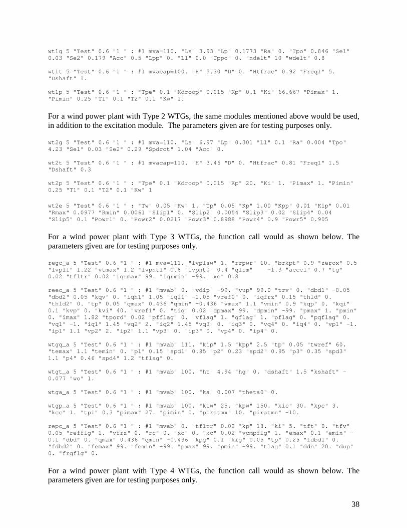
wt1g 5 "Test" 0.6 "1 " : #1 mva=110. "Ls" 3.93 "Lp" 0.1773 "Ra" 0. "Tpo" 0.846 "Se1" 0.03 "Se2" 0.179 "Acc" 0.5 "Lpp" 0. "Ll" 0.0 "Tppo" 0. "ndelt" 10 "wdelt" 0.8 wt1t 5 "Test" 0.6 "1 " : #1 mvacap=100. "H" 5.30 "D" 0. "Htfrac" 0.92 "Freq1" 5. "Dshaft" 1. wt1p 5 "Test" 0.6 "1 " : "Tpe" 0.1 "Kdroop" 0.015 "Kp" 0.1 "Ki" 66.667 "Pimax" 1. "Pimin" 0.25 "T1" 0.1 "T2" 0.1 "Kw" 1. For a wind power plant with Type 2 WTGs, the same modules mentioned above would be used, in addition to the excitation module. The parameters given are for testing purposes only. wt2g 5 "Test" 0.6 "1 " : #1 mva=110. "Ls" 6.97 "Lp" 0.301 "Ll" 0.1 "Ra" 0.004 "Tpo" 4.23 "Se1" 0.03 "Se2" 0.29 "Spdrot" 1.04 "Acc" 0. wt2t 5 "Test" 0.6 "1 " : #1 mvacap=110. "H" 3.46 "D" 0. "Htfrac" 0.81 "Freq1" 1.5 "Dshaft" 0.3 wt2p 5 "Test" 0.6 "1 " : "Tpe" 0.1 "Kdroop" 0.015 "Kp" 20. "Ki" 1. "Pimax" 1. "Pimin" 0.25 "T1" 0.1 "T2" 0.1 "Kw" 1
wt2e 5 "Test" 0.6 "1 " : "Tw" 0.05 "Kw" 1. "Tp" 0.05 "Kp" 1.00 "Kpp" 0.01 "Kip" 0.01 "Rmax" 0.0977 "Rmin" 0.0061 "Slip1" 0. "Slip2" 0.0054 "Slip3" 0.02 "Slip4" 0.04 "Slip5" 0.1 "Powr1" 0. "Powr2" 0.0217 "Powr3" 0.8988 "Powr4" 0.9 "Powr5" 0.905 For a wind power plant with Type 3 WTGs, the function call would as shown below. The parameters given are for testing purposes only. regc_a 5 "Test" 0.6 "1 " : #1 mva=111. "lvplsw" 1. "rrpwr" 10. "brkpt" 0.9 "zerox" 0.5 "lvpl1" 1.22 "vtmax" 1.2 "lvpnt1" 0.8 "lvpnt0" 0.4 "qlim" -1.3 "accel" 0.7 "tg" 0.02 "tfltr" 0.02 "iqrmax" 99. "iqrmin" -99. "xe" 0.8 reec_a 5 "Test" 0.6 "1 " : #1 "mvab" 0. "vdip" -99. "vup" 99.0 "trv" 0. "dbd1" -0.05 "dbd2" 0.05 "kqv" 0. "iqh1" 1.05 "iql1" -1.05 "vref0" 0. "iqfrz" 0.15 "thld" 0. "thld2" 0. "tp" 0.05 "qmax" 0.436 "qmin" -0.436 "vmax" 1.1 "vmin" 0.9 "kqp" 0. "kqi" 0.1 "kvp" 0. "kvi" 40. "vref1" 0. "tiq" 0.02 "dpmax" 99. "dpmin" -99. "pmax" 1. "pmin" 0. "imax" 1.82 "tpord" 0.02 "pfflag" 0. "vflag" 1. "qflag" 1. "pflag" 0. "pqflag" 0. "vq1" -1. "iq1" 1.45 "vq2" 2. "iq2" 1.45 "vq3" 0. "iq3" 0. "vq4" 0. "iq4" 0. "vp1" -1. "ip1" 1.1 "vp2" 2. "ip2" 1.1 "vp3" 0. "ip3" 0. "vp4" 0. "ip4" 0. wtgq_a 5 "Test" 0.6 "1 " : #1 "mvab" 111. "kip" 1.5 "kpp" 2.5 "tp" 0.05 "twref" 60. "temax" 1.1 "temin" 0. "p1" 0.15 "spd1" 0.85 "p2" 0.23 "spd2" 0.95 "p3" 0.35 "spd3" 1.1 "p4" 0.46 "spd4" 1.2 "tflag" 0. wtgt_a 5 "Test" 0.6 "1 " : #1 "mvab" 100. "ht" 4.94 "hg" 0. "dshaft" 1.5 "kshaft" -0.077 "wo" 1. wtga_a 5 "Test" 0.6 "1 " : #1 "mvab" 100. "ka" 0.007 "theta0" 0. wtgp_a 5 "Test" 0.6 "1 " : #1 "mvab" 100. "kiw" 25. "kpw" 150. "kic" 30. "kpc" 3. "kcc" 1. "tpi" 0.3 "pimax" 27. "pimin" 0. "piratmx" 10. "piratmn" -10. repc_a 5 "Test" 0.6 "1 " : #1 "mvab" 0. "tfltr" 0.02 "kp" 18. "ki" 5. "tft" 0. "tfv" 0.05 "refflg" 1. "vfrz" 0. "rc" 0. "xc" 0. "kc" 0.02 "vcmpflg" 1. "emax" 0.1 "emin" -0.1 "dbd" 0. "qmax" 0.436 "qmin" -0.436 "kpg" 0.1 "kig" 0.05 "tp" 0.25 "fdbd1" 0. "fdbd2" 0. "femax" 99. "femin" -99. "pmax" 99. "pmin" -99. "tlag" 0.1 "ddn" 20. "dup" 0. "frqflg" 0. For a wind power plant with Type 4 WTGs, the function call would as shown below. The parameters given are for testing purposes only.
39
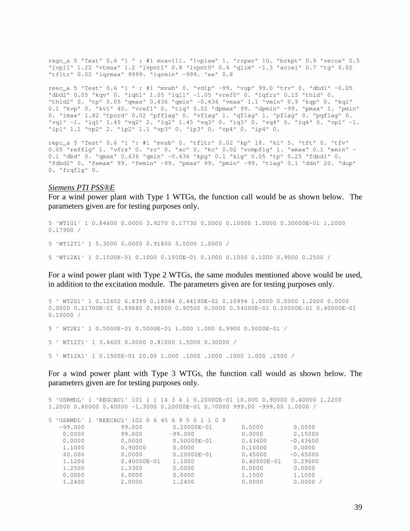
regc_a 5 "Test" 0.6 "1 " : #1 mva=111. "lvplsw" 1. "rrpwr" 10. "brkpt" 0.9 "zerox" 0.5 "lvpl1" 1.22 "vtmax" 1.2 "lvpnt1" 0.8 "lvpnt0" 0.4 "qlim" -1.3 "accel" 0.7 "tg" 0.02 "tfltr" 0.02 "iqrmax" 9999. "iqrmin" -999. "xe" 0.8 reec_a 5 "Test" 0.6 "1 " : #1 "mvab" 0. "vdip" -99. "vup" 99.0 "trv" 0. "dbd1" -0.05 "dbd2" 0.05 "kqv" 0. "iqh1" 1.05 "iql1" -1.05 "vref0" 0. "iqfrz" 0.15 "thld" 0. "thld2" 0. "tp" 0.05 "qmax" 0.436 "qmin" -0.436 "vmax" 1.1 "vmin" 0.9 "kqp" 0. "kqi" 0.1 "kvp" 0. "kvi" 40. "vref1" 0. "tiq" 0.02 "dpmax" 99. "dpmin" -99. "pmax" 1. "pmin" 0. "imax" 1.82 "tpord" 0.02 "pfflag" 0. "vflag" 1. "qflag" 1. "pflag" 0. "pqflag" 0. "vq1" -1. "iq1" 1.45 "vq2" 2. "iq2" 1.45 "vq3" 0. "iq3" 0. "vq4" 0. "iq4" 0. "vp1" -1. "ip1" 1.1 "vp2" 2. "ip2" 1.1 "vp3" 0. "ip3" 0. "vp4" 0. "ip4" 0. repc_a 5 "Test" 0.6 "1 ": #1 "mvab" 0. "tfltr" 0.02 "kp" 18. "ki" 5. "tft" 0. "tfv" 0.05 "refflg" 1. "vfrz" 0. "rc" 0. "xc" 0. "kc" 0.02 "vcmpflg" 1. "emax" 0.1 "emin" -0.1 "dbd" 0. "qmax" 0.436 "qmin" -0.436 "kpg" 0.1 "kig" 0.05 "tp" 0.25 "fdbd1" 0. "fdbd2" 0. "femax" 99. "femin" -99. "pmax" 99. "pmin" -99. "tlag" 0.1 "ddn" 20. "dup" 0. "frqflg" 0. Siemens PTI PSS®E For a wind power plant with Type 1 WTGs, the function call would be as shown below. The parameters given are for testing purposes only. 5 'WT1G1' 1 0.84600 0.0000 3.9270 0.17730 0.0000 0.10000 1.0000 0.30000E-01 1.2000 0.17900 / 5 'WT12T1' 1 5.3000 0.0000 0.91800 5.0000 1.0000 / 5 'WT12A1' 1 0.1500E-01 0.1000 0.1500E-01 0.1000 0.1000 0.1000 0.9000 0.2500 /
For a wind power plant with Type 2 WTGs, the same modules mentioned above would be used, in addition to the excitation module. The parameters given are for testing purposes only. 5 ' WT2G1' 1 0.12602 6.8399 0.18084 0.44190E-02 0.10994 1.0000 0.0000 1.2000 0.0000 0.0000 0.21700E-01 0.89880 0.90000 0.90500 0.0000 0.54000E-02 0.20000E-01 0.40000E-01 0.10000 / 5 ' WT2E1' 1 0.5000E-01 0.5000E-01 1.000 1.000 0.9900 0.5000E-01 / 5 ' WT12T1' 1 3.4600 0.0000 0.81000 1.5000 0.30000 / 5 ' WT12A1' 1 0.1500E-01 20.00 1.000 .1000 .1000 .1000 1.000 .2500 /
For a wind power plant with Type 3 WTGs, the function call would as shown below. The parameters given are for testing purposes only. 5 'USRMDL' 1 'REGCAU1' 101 1 1 14 3 4 1 0.20000E-01 10.000 0.90000 0.40000 1.2200 1.2000 0.80000 0.40000 -1.3000 0.20000E-01 0.70000 999.00 -999.00 1.0000 / 5 'USRMDL' 1 'REECAU1' 102 0 6 45 6 9 5 0 1 1 0 0 -99.000 99.000 0.20000E-01 0.0000 0.0000 0.0000 99.000 -99.000 0.0000 0.15000 0.0000 0.0000 0.50000E-01 0.43600 -0.43600 1.1000 0.90000 0.0000 0.10000 0.0000 40.000 0.0000 0.20000E-01 0.45000 -0.45000 1.1200 0.40000E-01 1.1000 0.40000E-01 0.29000 1.2500 1.3300 0.0000 0.0000 0.0000 0.0000 0.0000 0.0000 1.1500 1.1000 1.2400 2.0000 1.2400 0.0000 0.0000 /
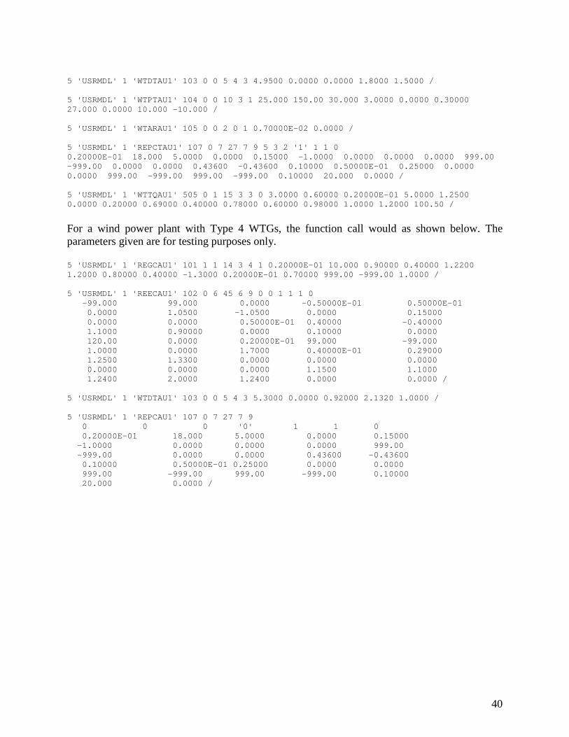
40
5 'USRMDL' 1 'WTDTAU1' 103 0 0 5 4 3 4.9500 0.0000 0.0000 1.8000 1.5000 / 5 'USRMDL' 1 'WTPTAU1' 104 0 0 10 3 1 25.000 150.00 30.000 3.0000 0.0000 0.30000 27.000 0.0000 10.000 -10.000 / 5 'USRMDL' 1 'WTARAU1' 105 0 0 2 0 1 0.70000E-02 0.0000 / 5 'USRMDL' 1 'REPCTAU1' 107 0 7 27 7 9 5 3 2 '1' 1 1 0 0.20000E-01 18.000 5.0000 0.0000 0.15000 -1.0000 0.0000 0.0000 0.0000 999.00 -999.00 0.0000 0.0000 0.43600 -0.43600 0.10000 0.50000E-01 0.25000 0.0000 0.0000 999.00 -999.00 999.00 -999.00 0.10000 20.000 0.0000 / 5 'USRMDL' 1 'WTTQAU1' 505 0 1 15 3 3 0 3.0000 0.60000 0.20000E-01 5.0000 1.2500 0.0000 0.20000 0.69000 0.40000 0.78000 0.60000 0.98000 1.0000 1.2000 100.50 /
For a wind power plant with Type 4 WTGs, the function call would as shown below. The parameters given are for testing purposes only. 5 'USRMDL' 1 'REGCAU1' 101 1 1 14 3 4 1 0.20000E-01 10.000 0.90000 0.40000 1.2200 1.2000 0.80000 0.40000 -1.3000 0.20000E-01 0.70000 999.00 -999.00 1.0000 / 5 'USRMDL' 1 'REECAU1' 102 0 6 45 6 9 0 0 1 1 1 0 -99.000 99.000 0.0000 -0.50000E-01 0.50000E-01 0.0000 1.0500 -1.0500 0.0000 0.15000 0.0000 0.0000 0.50000E-01 0.40000 -0.40000 1.1000 0.90000 0.0000 0.10000 0.0000 120.00 0.0000 0.20000E-01 99.000 -99.000 1.0000 0.0000 1.7000 0.40000E-01 0.29000 1.2500 1.3300 0.0000 0.0000 0.0000 0.0000 0.0000 0.0000 1.1500 1.1000 1.2400 2.0000 1.2400 0.0000 0.0000 / 5 'USRMDL' 1 'WTDTAU1' 103 0 0 5 4 3 5.3000 0.0000 0.92000 2.1320 1.0000 / 5 'USRMDL' 1 'REPCAU1' 107 0 7 27 7 9 0 0 0 '0' 1 1 0 0.20000E-01 18.000 5.0000 0.0000 0.15000 -1.0000 0.0000 0.0000 0.0000 999.00 -999.00 0.0000 0.0000 0.43600 -0.43600 0.10000 0.50000E-01 0.25000 0.0000 0.0000 999.00 -999.00 999.00 -999.00 0.10000 20.000 0.0000 /

41
Document Version Control
• March 10, 2014 – Original draft by Sandia National Laboratories (Ellis, Karlson) • March 14, 2014 – Corrected figures and tables for pseudo-governor and toque control
modules (Karlson, Ellis) • March 21, 2014 – Added reference link to folder containing model specifications in
Section 1.1. Added caveat in Section 3.1 regarding voltage spikes. (Ellis) • April 4, 2014 – Editorial changes from I. Green, CAISO, P. Pourbeik, EPRI • April 8, 2014 – Added Appendix B – Model Function Calls (Karlson, Weber, Senthil)