docsis 3 - bowe.id.au · – docsis 3.0 interface specifications (released december 2006) – cpe...
TRANSCRIPT
Docsis 3
© 2010 JDSU. All rights reserved. JDSU CONFIDENTIAL & PROPRIETARY INFORMATION 30
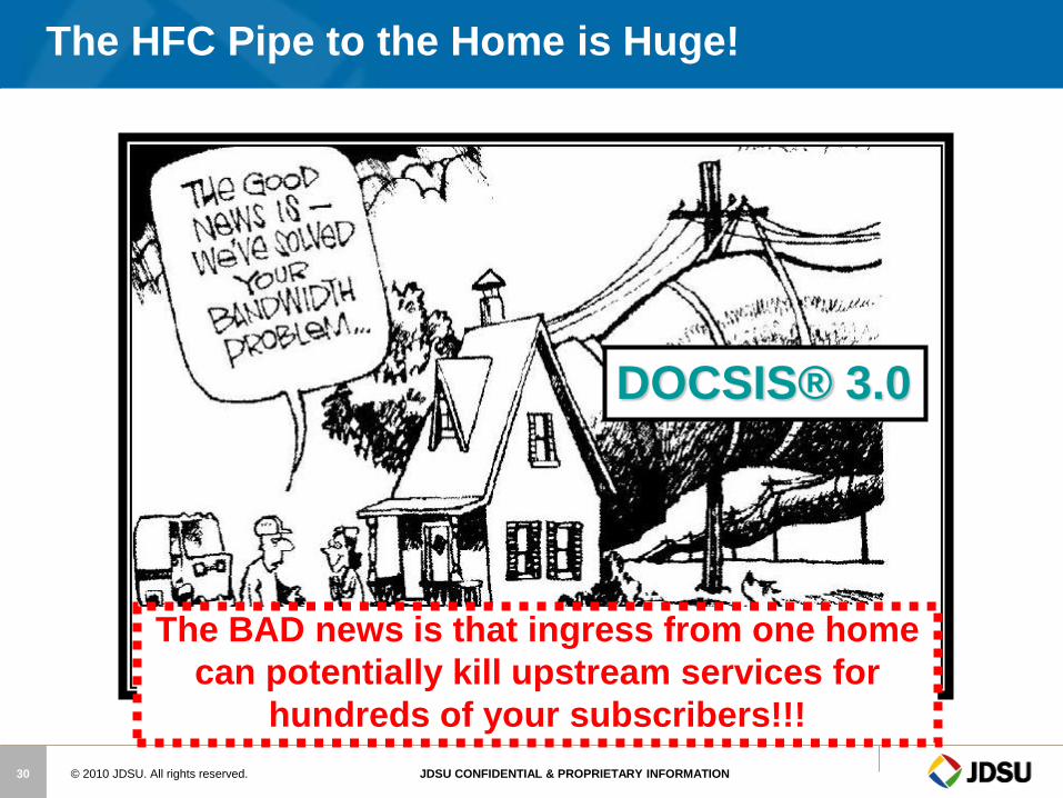
The HFC Pipe to the Home is Huge!
The BAD news is that ingress from one home
can potentially kill upstream services for
hundreds of your subscribers!!!
DOCSIS® 3.0
© 2010 JDSU. All rights reserved. JDSU CONFIDENTIAL & PROPRIETARY INFORMATION 31
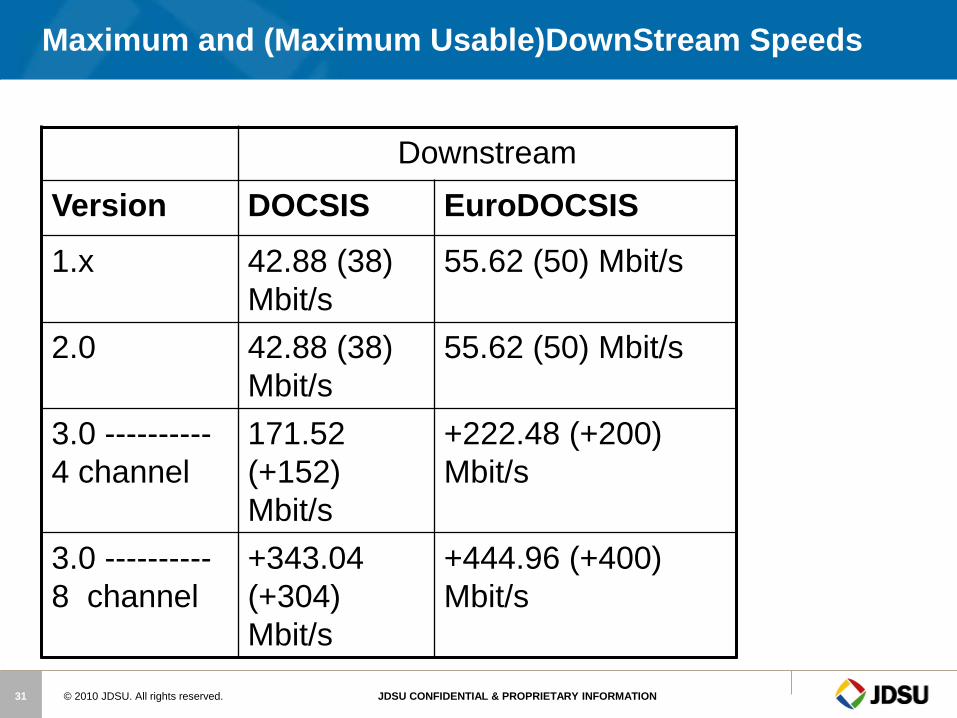
Maximum and (Maximum Usable)DownStream Speeds
Downstream
Version DOCSIS EuroDOCSIS
1.x 42.88 (38)
Mbit/s
55.62 (50) Mbit/s
2.0 42.88 (38)
Mbit/s
55.62 (50) Mbit/s
3.0 ----------
4 channel
171.52
(+152)
Mbit/s
+222.48 (+200)
Mbit/s
3.0 ----------
8 channel
+343.04
(+304)
Mbit/s
+444.96 (+400)
Mbit/s

© 2010 JDSU. All rights reserved. JDSU CONFIDENTIAL & PROPRIETARY INFORMATION 32
New Specifications
– DOCSIS 3.0 Interface Specifications (released December 2006)
– CPE equipment in development stages( Bronze, Silver, Full)
Downstream data rates of 160 Mbps or higher
– Channel Bonding
– 4 or more channels
Upstream data rates of 120 Mbps or higher
– Channel Bonding
– 4 or more channels
Internet Protocol version 6 (IPv6)
– IPv6 greatly expands the number of IP addresses
• Expands IP address space from 32 bits to 128 bits
• IPv6 supports 3.4×1038 addresses;
• Colon-Hexadecimal Format
100% backward compatible with DOCSIS 1.0/1.1/2.0
1 x 256QAM => “up to” ~40Mbps
1 x 64QAM => “up to” ~30Mbps
4923:2A1C:0DB8:04F3:AEB5:96F0:E08C:FFEC
DOCSIS® 3.0 Overview
4 x 256QAM => “up to” ~160 Mbps
4 x 64QAM => “up to” ~120
Mbps
© 2010 JDSU. All rights reserved. JDSU CONFIDENTIAL & PROPRIETARY INFORMATION 33
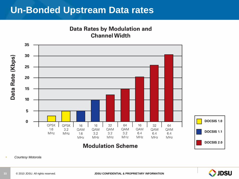
Un-Bonded Upstream Data rates
Courtesy Motorola
© 2010 JDSU. All rights reserved. JDSU CONFIDENTIAL & PROPRIETARY INFORMATION 35
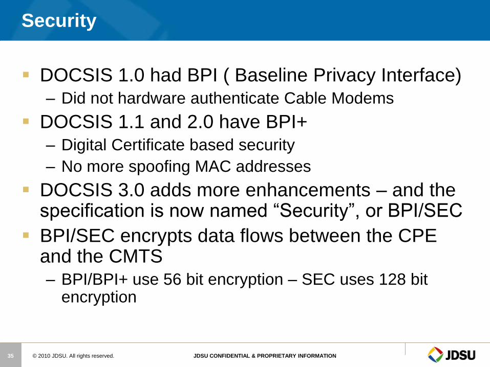
Security
DOCSIS 1.0 had BPI ( Baseline Privacy Interface) – Did not hardware authenticate Cable Modems
DOCSIS 1.1 and 2.0 have BPI+ – Digital Certificate based security
– No more spoofing MAC addresses
DOCSIS 3.0 adds more enhancements – and the specification is now named “Security”, or BPI/SEC
BPI/SEC encrypts data flows between the CPE and the CMTS – BPI/BPI+ use 56 bit encryption – SEC uses 128 bit
encryption
© 2010 JDSU. All rights reserved. JDSU CONFIDENTIAL & PROPRIETARY INFORMATION 36
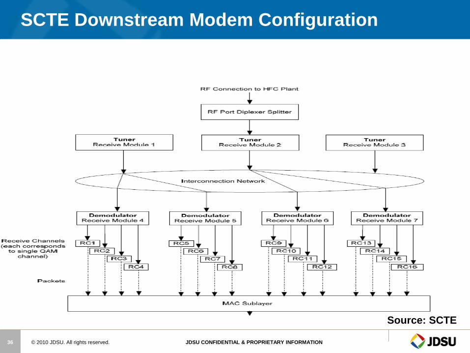
SCTE Downstream Modem Configuration
Source: SCTE

© 2010 JDSU. All rights reserved. JDSU CONFIDENTIAL & PROPRIETARY INFORMATION 37
SCTE Docsis 3.0 Downstream RF Spec
Source: SCTE

© 2010 JDSU. All rights reserved. JDSU CONFIDENTIAL & PROPRIETARY INFORMATION 38
SCTE Docsis 3.0 Upstream RF Spec
Source: SCTE
© 2010 JDSU. All rights reserved. JDSU CONFIDENTIAL & PROPRIETARY INFORMATION 39
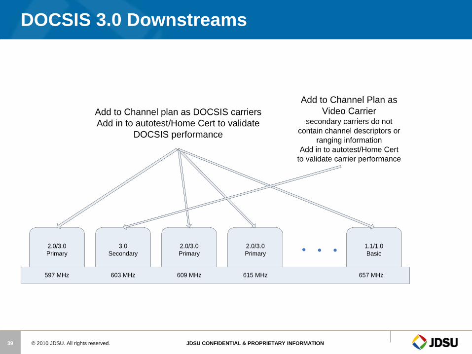
DOCSIS 3.0 Downstreams
2.0/3.0
Primary
3.0
Secondary
2.0/3.0
Primary
2.0/3.0
Primary
1.1/1.0
Basic
597 MHz 603 MHz 609 MHz 615 MHz 657 MHz
Add to Channel plan as DOCSIS carriers
Add in to autotest/Home Cert to validate
DOCSIS performance
Add to Channel Plan as
Video Carrier secondary carriers do not
contain channel descriptors or
ranging information
Add in to autotest/Home Cert
to validate carrier performance
© 2010 JDSU. All rights reserved. JDSU CONFIDENTIAL & PROPRIETARY INFORMATION 40
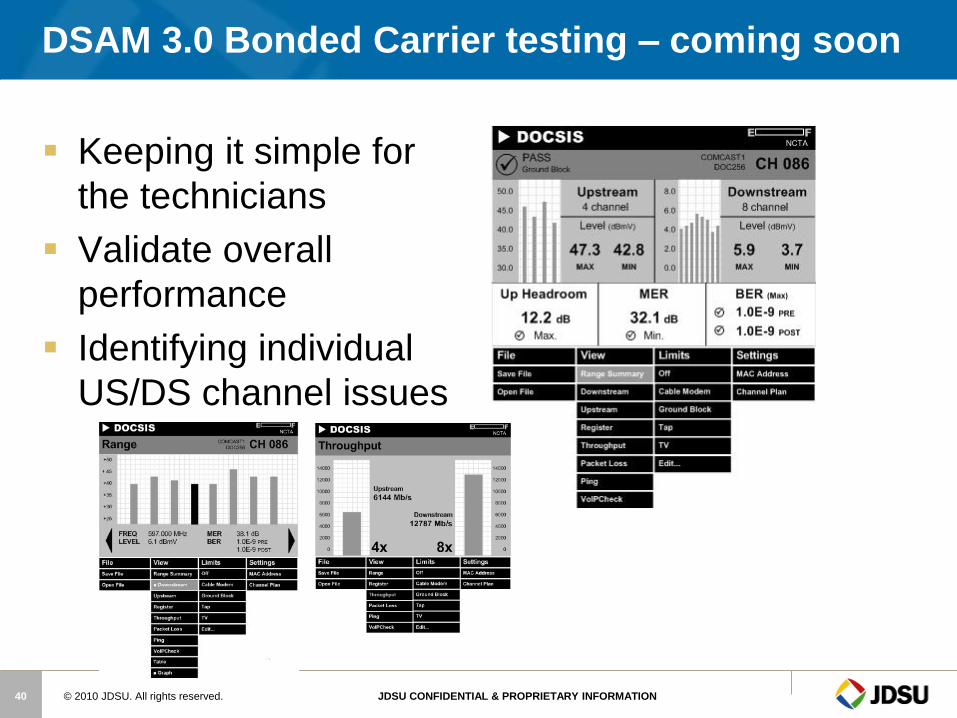
DSAM 3.0 Bonded Carrier testing – coming soon
Keeping it simple for
the technicians
Validate overall
performance
Identifying individual
US/DS channel issues

© 2010 JDSU. All rights reserved. JDSU CONFIDENTIAL & PROPRIETARY INFORMATION 41
BER Example
A 256QAM channel transmits at a symbol rate of 5M
symbols per second
Bit rate = 8 bits per symbol X 5M symbol per second
=40M bits per second
Error Incident = Bit rate X BER = Errors Per Second
BER Error Frequency Error Incident
10-12 1 in 1 Trillion bits 25000 secs between errs (6.94 hrs)
10-11 1 in 100 Billion bits 2500 secs between errs (41.67 mins)
10-10 1 in 10 Billion bits 250 secs between errs (4.167 mins) 10-9 1 in 1 Billion bits 25 seconds between errors
10-8 1 in 100 Million bits 2.5 seconds between errors 10-7 1 in 10 Million bits 4 errors per second 10-6 1 in 1 Million bits 40 errors per second
10-5 1 in 100 Thousand bits 400 errors per second
10-4 1 in 10 Thousand Bits 4000 errors per second
10-3 1 in 1 Thousand bits 40000 errors per second
Sweep and Maintenance
© 2010 JDSU. All rights reserved. JDSU CONFIDENTIAL & PROPRIETARY INFORMATION 43
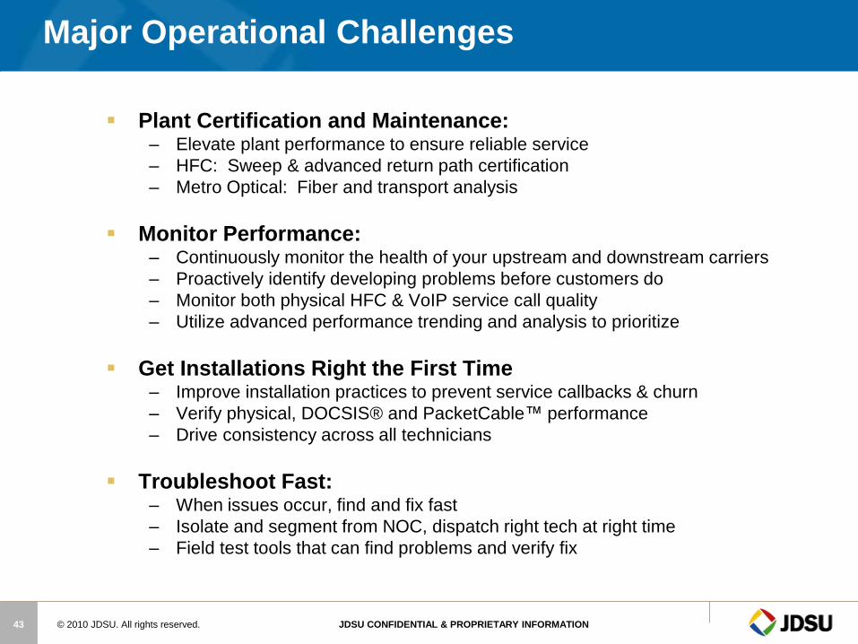
Major Operational Challenges
Plant Certification and Maintenance: – Elevate plant performance to ensure reliable service
– HFC: Sweep & advanced return path certification
– Metro Optical: Fiber and transport analysis
Monitor Performance: – Continuously monitor the health of your upstream and downstream carriers
– Proactively identify developing problems before customers do
– Monitor both physical HFC & VoIP service call quality
– Utilize advanced performance trending and analysis to prioritize
Get Installations Right the First Time – Improve installation practices to prevent service callbacks & churn
– Verify physical, DOCSIS® and PacketCable™ performance
– Drive consistency across all technicians
Troubleshoot Fast: – When issues occur, find and fix fast
– Isolate and segment from NOC, dispatch right tech at right time
– Field test tools that can find problems and verify fix
© 2010 JDSU. All rights reserved. JDSU CONFIDENTIAL & PROPRIETARY INFORMATION 44
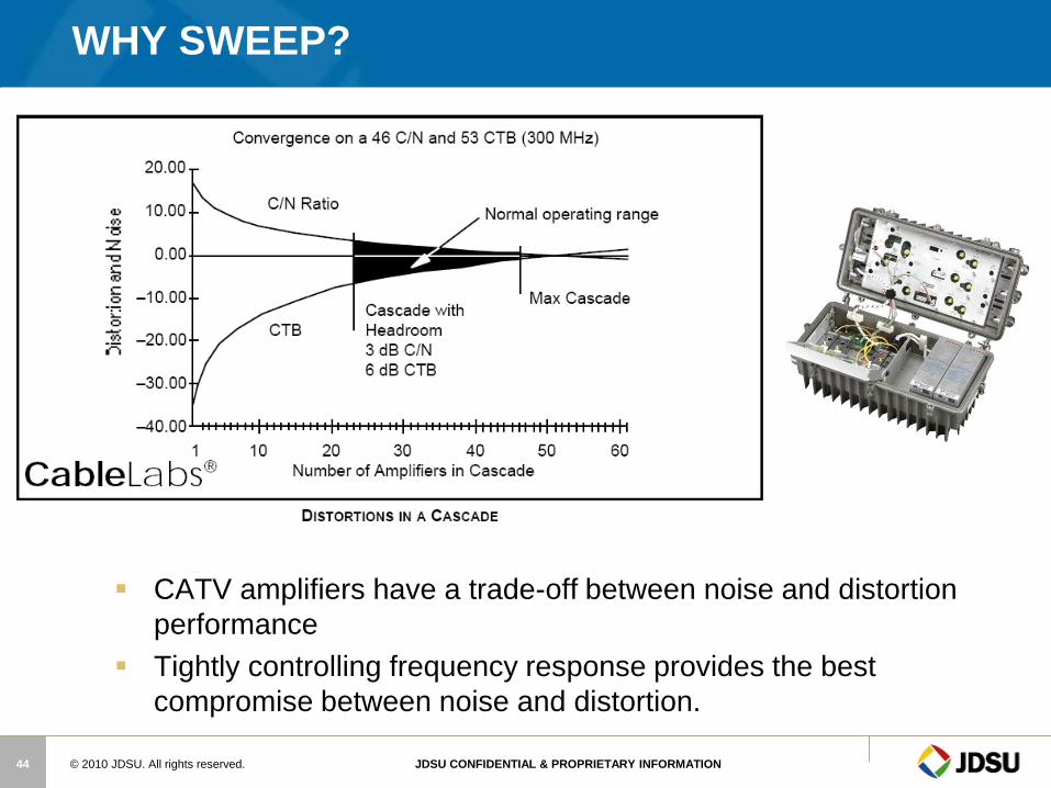
CATV amplifiers have a trade-off between noise and distortion
performance
Tightly controlling frequency response provides the best
compromise between noise and distortion.
WHY SWEEP?
© 2010 JDSU. All rights reserved. JDSU CONFIDENTIAL & PROPRIETARY INFORMATION 45
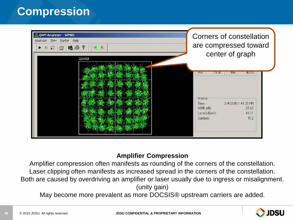
Amplifier Compression
Amplifier compression often manifests as rounding of the corners of the constellation.
Laser clipping often manifests as increased spread in the corners of the constellation.
Both are caused by overdriving an amplifier or laser usually due to ingress or misalignment.
(unity gain)
May become more prevalent as more DOCSIS® upstream carriers are added.
Compression
Corners of constellation
are compressed toward
center of graph

© 2010 JDSU. All rights reserved. JDSU CONFIDENTIAL & PROPRIETARY INFORMATION 46
Incorrect Levels
Low Video Levels
Produces noise in
the picture
• High Video Levels
Produces distortion in
the picture

© 2010 JDSU. All rights reserved. JDSU CONFIDENTIAL & PROPRIETARY INFORMATION 47
Low Digital levels
Causes Digital signal to
Degrade.
This causes Tiling and Loss
of high Speed internet
access.
© 2010 JDSU. All rights reserved. JDSU CONFIDENTIAL & PROPRIETARY INFORMATION 48
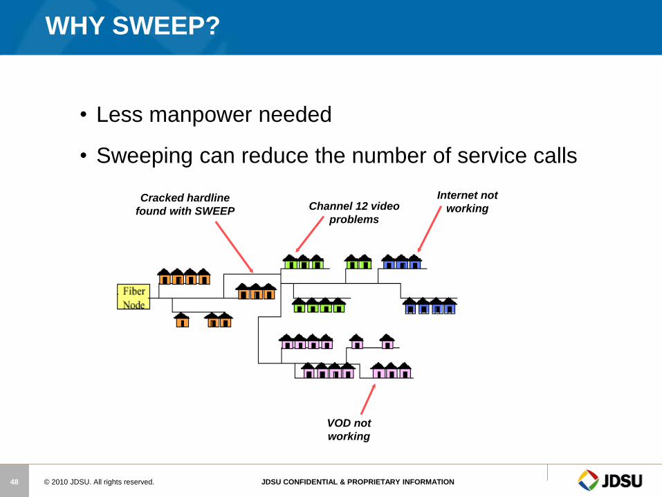
• Less manpower needed
• Sweeping can reduce the number of service calls
VOD not
working
Internet not
working Channel 12 video
problems
Cracked hardline
found with SWEEP
WHY SWEEP?
© 2010 JDSU. All rights reserved. JDSU CONFIDENTIAL & PROPRIETARY INFORMATION 49
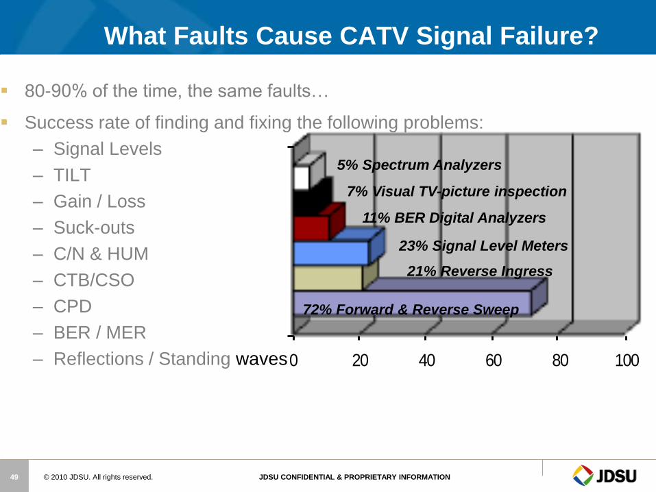
0 20 40 60 80 100
121% Reverse Ingress
23% Signal Level Meters
11% BER Digital Analyzers
72% Forward & Reverse Sweep
5% Spectrum Analyzers
7% Visual TV-picture inspection
What Faults Cause CATV Signal Failure?
80-90% of the time, the same faults…
Success rate of finding and fixing the following problems:
– Signal Levels
– TILT
– Gain / Loss
– Suck-outs
– C/N & HUM
– CTB/CSO
– CPD
– BER / MER
– Reflections / Standing waves
© 2010 JDSU. All rights reserved. JDSU CONFIDENTIAL & PROPRIETARY INFORMATION 50
Sweep Verifies Construction Quality
Sweep can find craftsmanship or component
problems that aren’t revealed with other tests
• Damaged cable
• Poor connectorization
• Amplifier RF response throughout its frequency range
• Gain
• Slope
• Loose face plates, seizure screws, module hardware…….
All of these issues could lead to major ingress and
micro-reflection problems!
© 2010 JDSU. All rights reserved. JDSU CONFIDENTIAL & PROPRIETARY INFORMATION 51
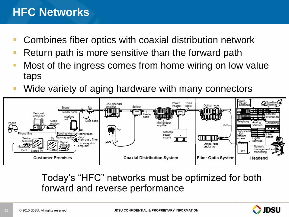
HFC Networks
Combines fiber optics with coaxial distribution network
Return path is more sensitive than the forward path
Most of the ingress comes from home wiring on low value taps
Wide variety of aging hardware with many connectors
Today’s “HFC” networks must be optimized for both forward and reverse performance
© 2010 JDSU. All rights reserved. JDSU CONFIDENTIAL & PROPRIETARY INFORMATION 52
Frequency response— Frequency response
problems are due to improper network
alignment, un-terminated lines, or damaged
components. When reverse frequency
response and equipment alignment have
been done incorrectly or not at all, the result
can be excessive thermal noise, distortions,
and group delay errors.
Impairments
© 2010 JDSU. All rights reserved. JDSU CONFIDENTIAL & PROPRIETARY INFORMATION 53
Forward System
Diverging System
Constant Outputs with Variable Inputs
Fixed Signals
– video / audio / digital carriers
System Noise
– is the sum of cascaded amplifiers
Balance or Align (Sweep)
– compensate for losses before the amp
© 2010 JDSU. All rights reserved. JDSU CONFIDENTIAL & PROPRIETARY INFORMATION 54
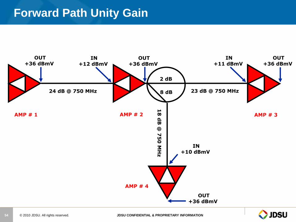
Forward Path Unity Gain
OUT +36 dBmV
OUT +36 dBmV
OUT +36 dBmV
OUT +36 dBmV
AMP # 1 AMP # 2 AMP # 3
AMP # 4
IN +12 dBmV
IN +11 dBmV
IN +10 dBmV
2 dB
8 dB 24 dB @ 750 MHz 23 dB @ 750 MHz
18
dB
@ 7
50
MH
z
© 2010 JDSU. All rights reserved. JDSU CONFIDENTIAL & PROPRIETARY INFORMATION 55
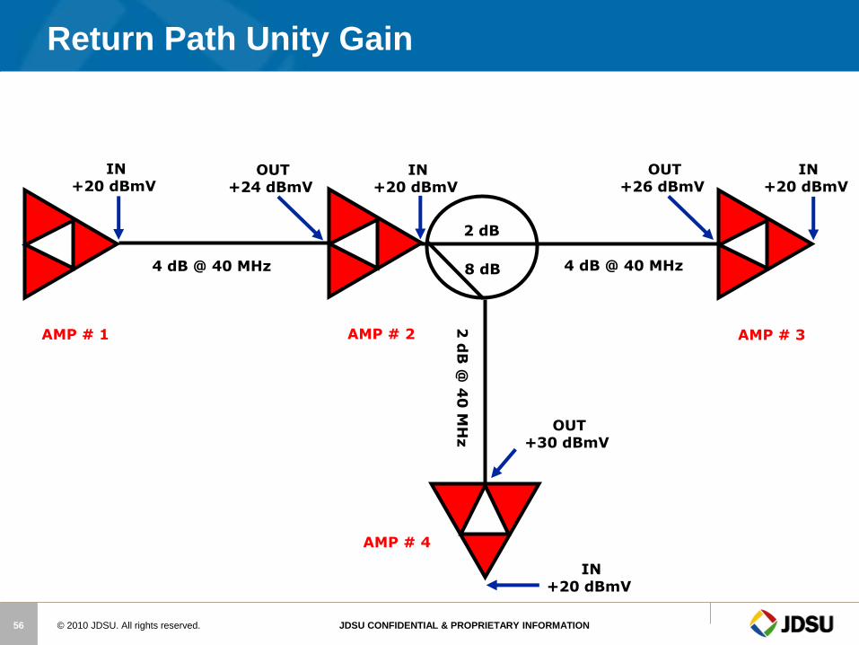
Reverse System
Converging System
Constant Inputs with Variable Outputs
No Fixed Signals
– impulse digital carriers
System Noise
– is the sum of all active components
Balance or Align (Sweep)
– compensate for losses after the amp
© 2010 JDSU. All rights reserved. JDSU CONFIDENTIAL & PROPRIETARY INFORMATION 56
Return Path Unity Gain
IN +20 dBmV
IN +20 dBmV
IN +20 dBmV
IN +20 dBmV
AMP # 1 AMP # 2 AMP # 3
AMP # 4
OUT +24 dBmV
OUT +26 dBmV
OUT +30 dBmV
2 dB
8 dB 4 dB @ 40 MHz 4 dB @ 40 MHz
2 d
B @
40
MH
z
© 2010 JDSU. All rights reserved. JDSU CONFIDENTIAL & PROPRIETARY INFORMATION 57
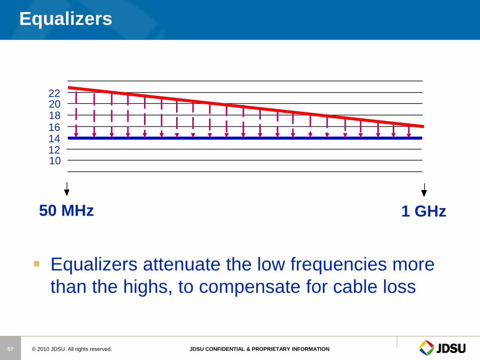
Equalizers
50 MHz
22 20 18 16 14 12 10
1 GHz
Equalizers attenuate the low frequencies more
than the highs, to compensate for cable loss

© 2010 JDSU. All rights reserved. JDSU CONFIDENTIAL & PROPRIETARY INFORMATION 58
Diplex Filter
A Diplex Filter separates signals by frequency
22
20
18
16
14
12
10
22
20
18
16
14
12
10
55MHz 750MHz 5MHz 55MHz 750MHz
22
20
18
16
14
12
10
5MHz 42MHz
42MHz
© 2010 JDSU. All rights reserved. JDSU CONFIDENTIAL & PROPRIETARY INFORMATION 59
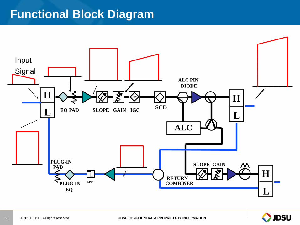
IGC
GAIN SLOPE
EQ PAD
RETURN COMBINER
SLOPE GAIN IGC
ALC PIN
DIODE
PLUG-IN
EQ
ALC
SCD
H
L
H
L
H
L
PLUG-IN PAD
LPF
Input
Signal
Functional Block Diagram
© 2010 JDSU. All rights reserved. JDSU CONFIDENTIAL & PROPRIETARY INFORMATION 61
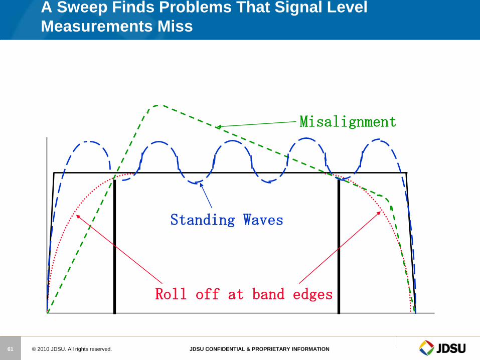
A Sweep Finds Problems That Signal Level
Measurements Miss
Standing Waves
Roll off at band edges
Misalignment
© 2010 JDSU. All rights reserved. JDSU CONFIDENTIAL & PROPRIETARY INFORMATION 62
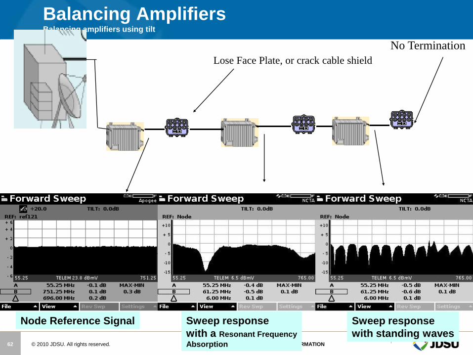
Balancing Amplifiers Balancing amplifiers using tilt
No Termination
Lose Face Plate, or crack cable shield
Node Reference Signal Sweep response
with a Resonant Frequency
Absorption
Sweep response
with standing waves
© 2010 JDSU. All rights reserved. JDSU CONFIDENTIAL & PROPRIETARY INFORMATION 63
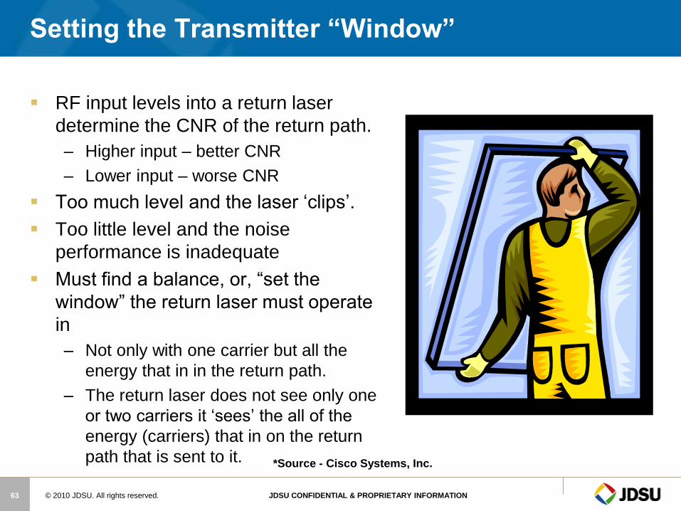
Setting the Transmitter “Window”
RF input levels into a return laser
determine the CNR of the return path.
– Higher input – better CNR
– Lower input – worse CNR
Too much level and the laser ‘clips’.
Too little level and the noise
performance is inadequate
Must find a balance, or, “set the
window” the return laser must operate
in
– Not only with one carrier but all the
energy that in in the return path.
– The return laser does not see only one
or two carriers it ‘sees’ the all of the
energy (carriers) that in on the return
path that is sent to it. *Source - Cisco Systems, Inc.
© 2010 JDSU. All rights reserved. JDSU CONFIDENTIAL & PROPRIETARY INFORMATION 64
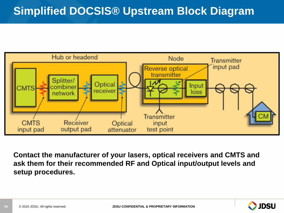
Simplified DOCSIS® Upstream Block Diagram
Contact the manufacturer of your lasers, optical receivers and CMTS and
ask them for their recommended RF and Optical input/output levels and
setup procedures.
© 2010 JDSU. All rights reserved. JDSU CONFIDENTIAL & PROPRIETARY INFORMATION 65
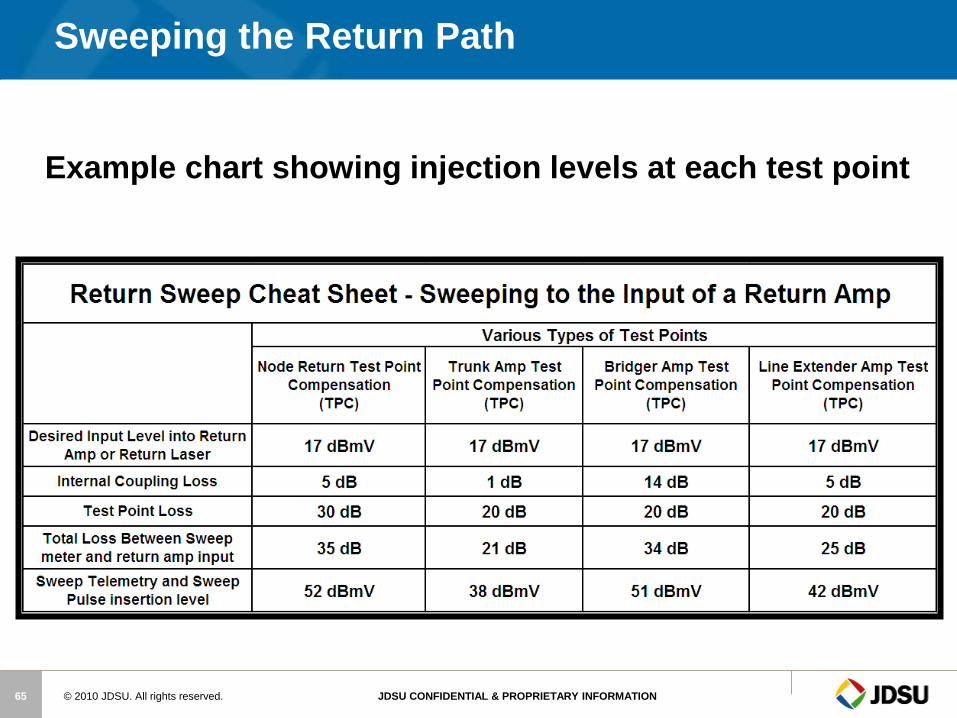
Example chart showing injection levels at each test point
Sweeping the Return Path
© 2010 JDSU. All rights reserved. JDSU CONFIDENTIAL & PROPRIETARY INFORMATION 66
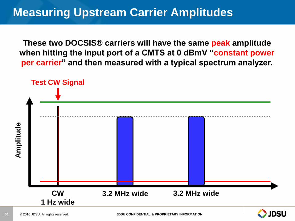
Measuring Upstream Carrier Amplitudes A
mp
litu
de
3.2 MHz wide CW
1 Hz wide
Test CW Signal
3.2 MHz wide
These two DOCSIS® carriers will have the same peak amplitude
when hitting the input port of a CMTS at 0 dBmV “constant power
per carrier” and then measured with a typical spectrum analyzer.

© 2010 JDSU. All rights reserved. JDSU CONFIDENTIAL & PROPRIETARY INFORMATION 67
Measuring Upstream Carrier Amplitudes A
mp
litu
de
3.2 MHz wide 6.4 MHz wide 1.6 MHz wide CW
1 Hz wide
Test CW Signal
These three DOCSIS® carriers will NOT have the same peak
amplitude when hitting the input port of a CMTS at 0 dBmV
“constant power per carrier” and then measured with a typical
spectrum analyzer or signal level meter.
© 2010 JDSU. All rights reserved. JDSU CONFIDENTIAL & PROPRIETARY INFORMATION 68
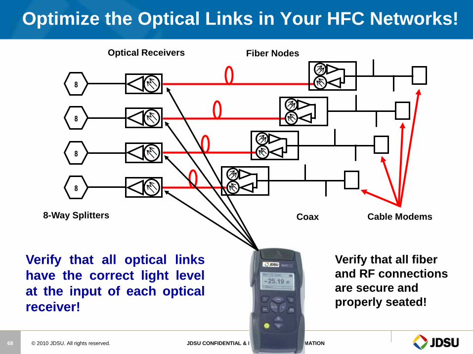
Optimize the Optical Links in Your HFC Networks!
Fiber Nodes Optical Receivers
8
8
8
8
Verify that all optical links
have the correct light level
at the input of each optical
receiver!
Coax Cable Modems
Verify that all fiber
and RF connections
are secure and
properly seated!
8-Way Splitters

© 2010 JDSU. All rights reserved. JDSU CONFIDENTIAL & PROPRIETARY INFORMATION 69
Optimize the RF Input to Return Sweep Transceiver
There are typically between 16 and 32 nodes
combined together for return path sweeping
Re
ve
rse
C
om
bin
er
X dBmV
FREQ
CHAN
ENTER
FCN CLEAR
help
status
alpha
light
abc def ghi
jkl mno pqr
stu vwx yz
space +/-
1 2 3
4 5 6
7 8 9
0 x
.
FILE
AUTO
SETUP
TILT SCAN LEVEL
C/N HUM MOD
SWEEP
SPECT
System Sweep Transmitter 3SR System Sweep Transmitter 3SR Stealth Sweep Stealth Sweep
X dBmV
X dBmV
X dBmV
Fiber Nodes Optical Receivers
40 dBmV
40 dBmV
40 dBmV
40 dBmV 8
8
8
8
Pad input of sweep receiver transceiver so that 40 dBmV into node equals 0 dBmV at the input of the return sweep transceiver
0 dBmV Pad
© 2010 JDSU. All rights reserved. JDSU CONFIDENTIAL & PROPRIETARY INFORMATION 70
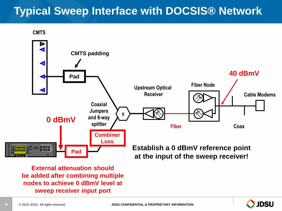
Cable Modems
Fiber Node
Typical Sweep Interface with DOCSIS® Network
Upstream Optical
Receiver
8
CMTS
Pad
CMTS padding
Pad
External attenuation should
be added after combining multiple
nodes to achieve 0 dBmV level at
sweep receiver input port
Fiber Coax
Coaxial
Jumpers
and 8-way
splitter
Establish a 0 dBmV reference point
at the input of the sweep receiver!
FREQ
CHAN
ENTER
FCN CLEAR
help
status
alpha
light
abc def ghi
jkl mno pqr
stu vwx yz
space +/-
1 2 3
4 5 6
7 8 9
0 x
.
FILE
AUTO
SETUP
TILT SCAN LEVEL
C/N HUM MOD
SWEEP
SPECT
System Sweep Transmitter System Sweep Transmitter Stealth Sweep Stealth Sweep
0 dBmV
40 dBmV
Combiner
Loss
© 2010 JDSU. All rights reserved. JDSU CONFIDENTIAL & PROPRIETARY INFORMATION 71
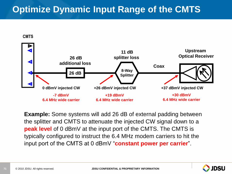
Optimize Dynamic Input Range of the CMTS
26 dB
26 dB
additional loss
Upstream
Optical Receiver
8-Way
Splitter
Coax
Example: Some systems will add 26 dB of external padding between
the splitter and CMTS to attenuate the injected CW signal down to a
peak level of 0 dBmV at the input port of the CMTS. The CMTS is
typically configured to instruct the 6.4 MHz modem carriers to hit the
input port of the CMTS at 0 dBmV “constant power per carrier”.
11 dB
splitter loss
+37 dBmV injected CW
+30 dBmV
6.4 MHz wide carrier
+26 dBmV injected CW
+19 dBmV
6.4 MHz wide carrier
0 dBmV injected CW
-7 dBmV
6.4 MHz wide carrier
CMTS
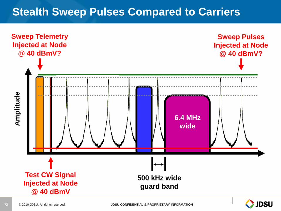
© 2010 JDSU. All rights reserved. JDSU CONFIDENTIAL & PROPRIETARY INFORMATION 72
Stealth Sweep Pulses Compared to Carriers A
mp
litu
de
Sweep Telemetry
Injected at Node
@ 40 dBmV?
Sweep Pulses
Injected at Node
@ 40 dBmV?
500 kHz wide
guard band
Test CW Signal
Injected at Node
@ 40 dBmV
6.4 MHz
wide

© 2010 JDSU. All rights reserved. JDSU CONFIDENTIAL & PROPRIETARY INFORMATION 73
3.2 MHz
wide
Stealth Sweep Pulses Compared to Carriers A
mp
litu
de
6.4 MHz
wide
6.4 MHz
wide
Stealth Sweep Pulses
Injected at Node
@ 40 dBmV?
Sweep Telemetry
Injected at Node
@ 40 dBmV?
6.4 MHz
wide
500 kHz 500 kHz 500 kHz Test CW Signal
Injected at Node
@ 40 dBmV
Peak level of 6.4 MHz
carriers at 34 dBmV

© 2010 JDSU. All rights reserved. JDSU CONFIDENTIAL & PROPRIETARY INFORMATION 74
Stealth Sweep Pulses Compared to Carriers A
mp
litu
de
6.4 MHz
wide
6.4 MHz
wide
Stealth Sweep Pulses
Injected at Node
@ 40 dBmV?
Sweep Telemetry
Injected at Node
@ 40 dBmV?
6.4 MHz
wide
100 kHz wide 100 kHz wide Test CW Signal
Injected at Node
@ 40 dBmV
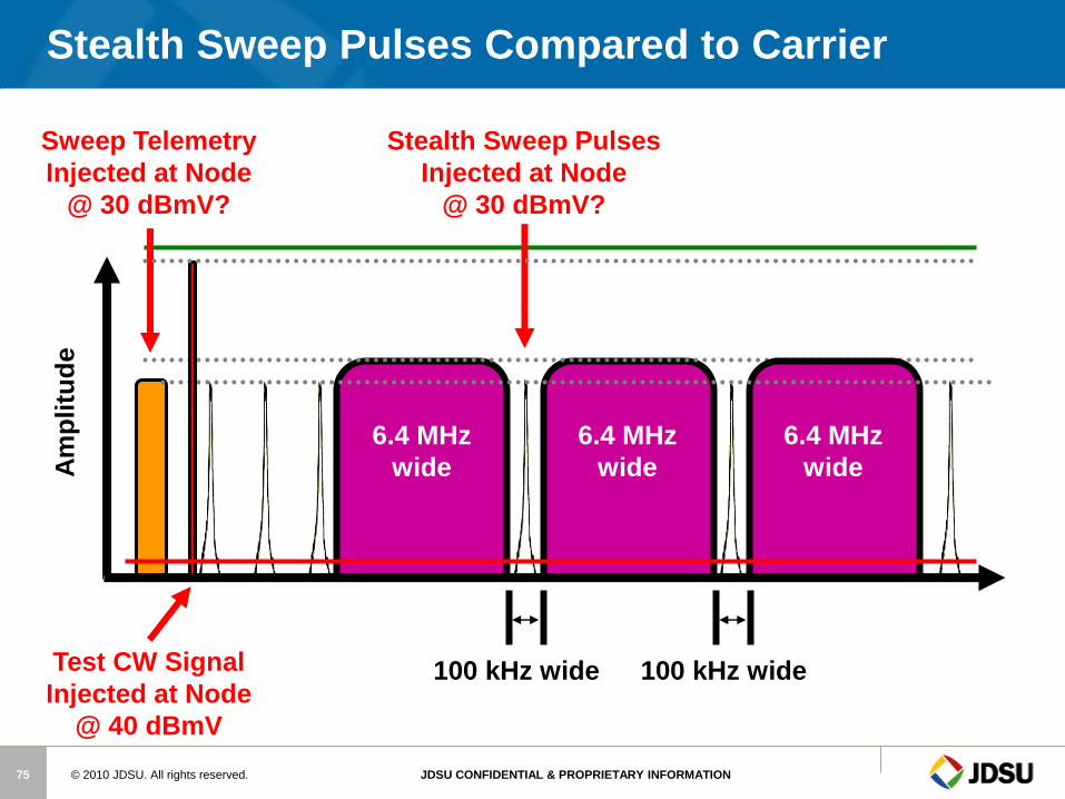
© 2010 JDSU. All rights reserved. JDSU CONFIDENTIAL & PROPRIETARY INFORMATION 75
Stealth Sweep Pulses Compared to Carrier A
mp
litu
de
6.4 MHz
wide
6.4 MHz
wide
Stealth Sweep Pulses
Injected at Node
@ 30 dBmV?
Sweep Telemetry
Injected at Node
@ 30 dBmV?
6.4 MHz
wide
100 kHz wide 100 kHz wide Test CW Signal
Injected at Node
@ 40 dBmV

© 2010 JDSU. All rights reserved. JDSU CONFIDENTIAL & PROPRIETARY INFORMATION 76
Sweeping the Node
Activation and maintenance of optical nodes by SDA-5000 + SDA-OPT2
Reverse-path
optical receivers
H
L
Forward Laser
Headend
SDA-5500 - Headend unit
FREQ
CHAN
ENTER
FCN CLEAR
help
status
alpha
light
abc def ghi
jkl mno pqr
stu vwx yz
space +/-
1 2
3
4 5 6
7 8 9
0
x
.
FILE
AUTO
SETUP
TILT SCAN LEVEL
C/N HUM MOD
SW EEP
SPECT
System Sweep Transmitter 3SR System Sweep Transmitter 3SR
Stealth Sweep Stealth Sweep
© 2010 JDSU. All rights reserved. JDSU CONFIDENTIAL & PROPRIETARY INFORMATION 77
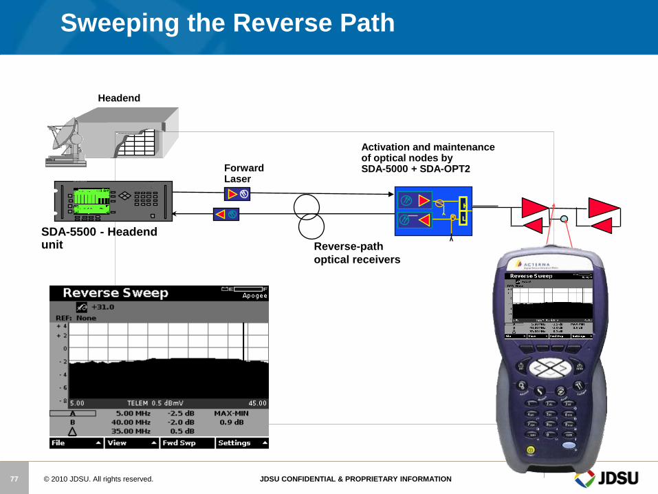
Sweeping the Reverse Path
Activation and maintenance of optical nodes by SDA-5000 + SDA-OPT2
Reverse-path
optical receivers
H
L
Forward Laser
Headend
SDA-5500 - Headend unit
FREQ
CHAN
ENTER
FCN CLEAR
help
status
alpha
light
abc def ghi
jkl mno pqr
stu vwx yz
space +/-
1 2
3
4 5 6
7 8 9
0
x
.
FILE
AUTO
SETUP
TILT SCAN LEVEL
C/N HUM MOD
SW EEP
SPECT
System Sweep Transmitter 3SR System Sweep Transmitter 3SR
Stealth Sweep Stealth Sweep
© 2010 JDSU. All rights reserved. JDSU CONFIDENTIAL & PROPRIETARY INFORMATION 78
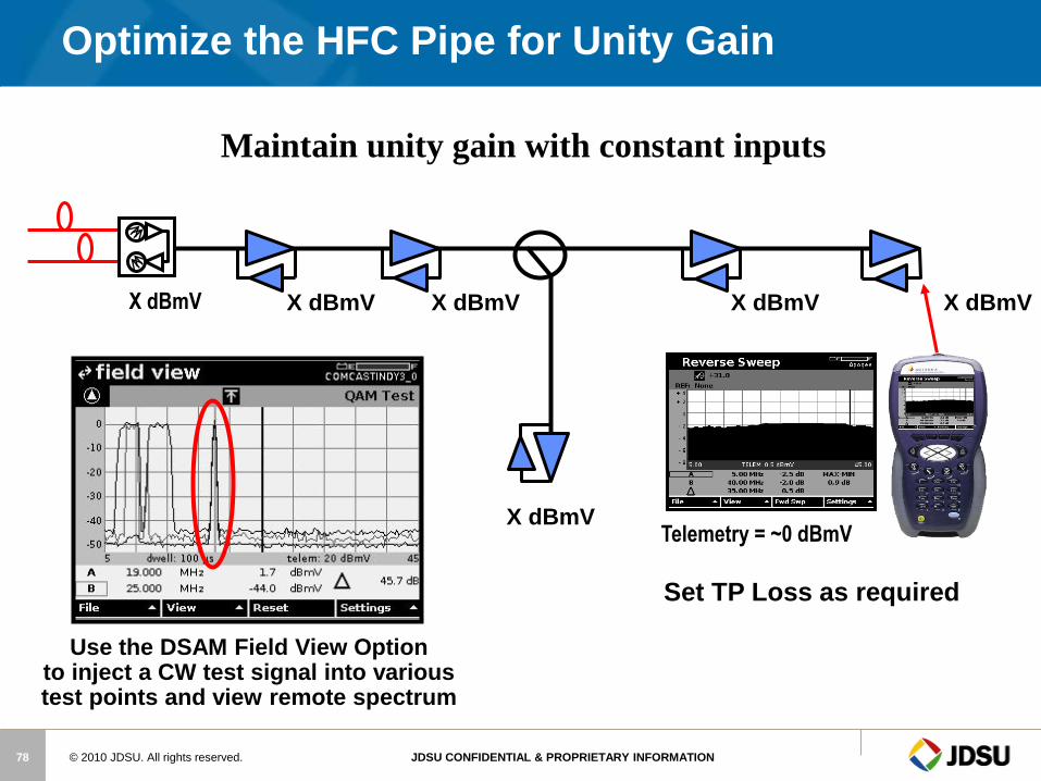
X dBmV
Maintain unity gain with constant inputs
X dBmV
X dBmV
X dBmV X dBmV
Optimize the HFC Pipe for Unity Gain
X dBmV
Telemetry = ~0 dBmV
Set TP Loss as required
Use the DSAM Field View Option to inject a CW test signal into various test points and view remote spectrum
© 2010 JDSU. All rights reserved. JDSU CONFIDENTIAL & PROPRIETARY INFORMATION 79
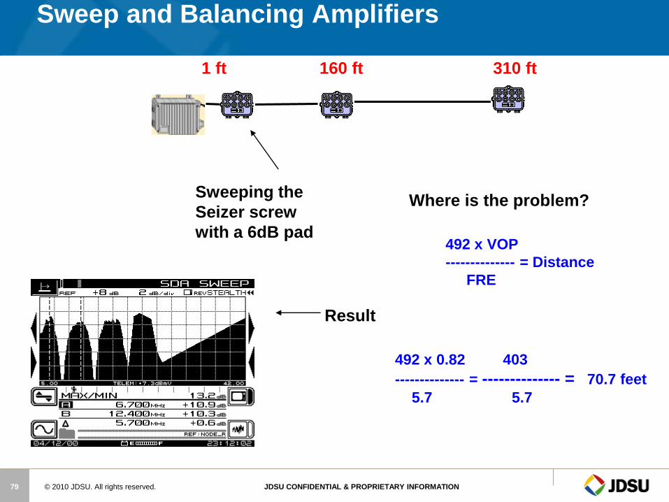
Sweep and Balancing Amplifiers
Sweeping the
Seizer screw
with a 6dB pad
Result
Where is the problem?
492 x 0.82 403
-------------- = -------------- = 70.7 feet
5.7 5.7
492 x VOP
-------------- = Distance
FRE
1 ft 160 ft 310 ft
© 2010 JDSU. All rights reserved. JDSU CONFIDENTIAL & PROPRIETARY INFORMATION 80
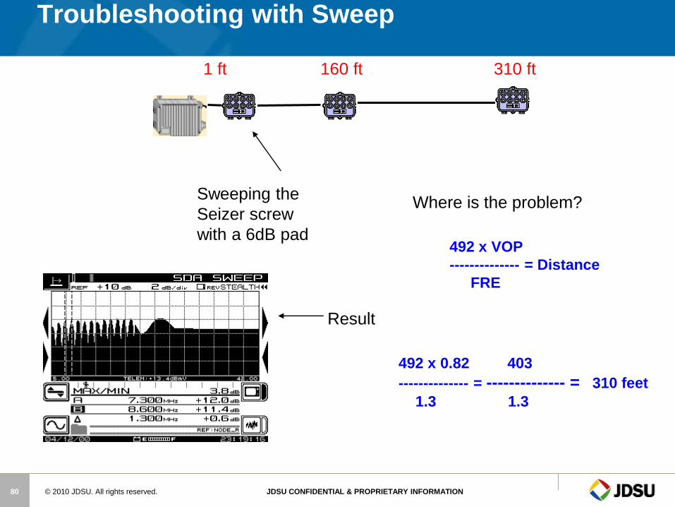
Troubleshooting with Sweep
Sweeping the
Seizer screw
with a 6dB pad
Result
Where is the problem?
492 x 0.82 403
-------------- = -------------- = 310 feet
1.3 1.3
492 x VOP
-------------- = Distance
FRE
1 ft 160 ft 310 ft

© 2010 JDSU. All rights reserved. JDSU CONFIDENTIAL & PROPRIETARY INFORMATION 81
Troubleshooting with Sweep
Sweeping the
Seizer screw
with a 6dB pad
Result
Where is the problem?
492 x 0.82 403
-------------- = -------------- = 310 feet
1.3 1.3
492 x VOP
-------------- = Distance
FRE
Terminate Tap
1 ft 160 ft 310 ft
© 2010 JDSU. All rights reserved. JDSU CONFIDENTIAL & PROPRIETARY INFORMATION 82
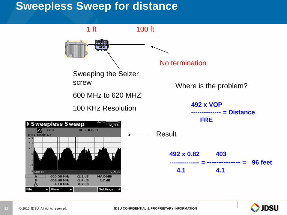
Sweepless Sweep for distance
Sweeping the Seizer
screw
600 MHz to 620 MHZ
100 KHz Resolution
Result
Where is the problem?
492 x 0.82 403
-------------- = -------------- = 96 feet
4.1 4.1
492 x VOP
-------------- = Distance
FRE
No termination
1 ft 100 ft

© 2010 JDSU. All rights reserved. JDSU CONFIDENTIAL & PROPRIETARY INFORMATION 83
Sweepless Sweep for distance
Sweeping the Seizer
screw
600 MHz to 620 MHZ
100 KHz Resolution
Result
Where is the problem?
No Problem
With
termination
1 ft 100 ft