doc:med 04(1157)c june 2012 draft for comments only …1157)c.pdf · draft for comments only ......
TRANSCRIPT
Doc:MED 04(1157)C June 2012
1
Draft for Comments Only
Draft Indian Standard Portable Solid Bio-Mass Cookstove (Chulha)
[First revision of 13152(Part 1):1991] ICS 97.040.20
________________________________________________________________________ Not to be reproduced without the permission of Last date for receipt of BIS or used as a STANDARD comments: 20 Aug 2012 ________________________________________________________________________ FOREWORD (Formal clause to be added later on) The Ministry of New and Renewable Energy (MNRE) launched National Biomass Cookstoves Initiative (NBCI) in 2009 with an aim to enhance the availability of clean and efficient energy for the energy deficient and poorer sections of the country. Under the initiative, a series of pilot scale projects were undertaken using several commercially available better cookstoves and different grades of process biomass fuel. The cookstoves technology has improved considerably in the past few years and those efforts need to be continued to further improve the designs to make them efficient and cost effective. The draft standard has been prepared for all types of portable biomass cookstoves (both family and community size). New designs of cookstoves have been added in this revision. Design B (HARSHA Multi-fuel cook stove) has been developed by Council of Scientific and Industrial Research, Govt of India and Design C (OORJA Cookstove) has been developed by the Indian Institute of Science, Bangalore. For the purpose of deciding whether a particular requirement of this standard is complied with, the final value, observed or calculated, expressing the result of a test or analysis, shall be rounded off in accordance with IS 2:1960 ‘Rules for rounding off numerical values (revised)’. The number of significant places retained in the rounded off value shall be the same as that of the specified value in this standard.
Doc:MED 04(1157)C June 2012
2
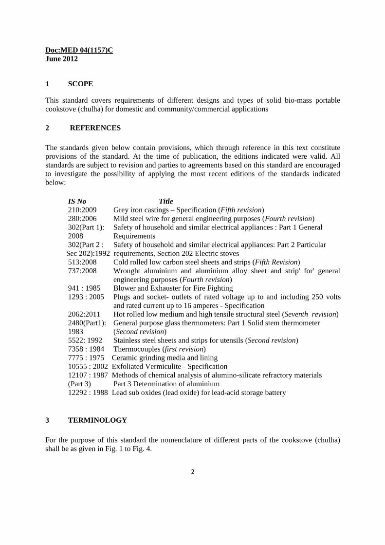
1 SCOPE
This standard covers requirements of different designs and types of solid bio-mass portable cookstove (chulha) for domestic and community/commercial applications 2 REFERENCES The standards given below contain provisions, which through reference in this text constitute provisions of the standard. At the time of publication, the editions indicated were valid. All standards are subject to revision and parties to agreements based on this standard are encouraged to investigate the possibility of applying the most recent editions of the standards indicated below:
IS No Title 210:2009 Grey iron castings – Specification (Fifth revision) 280:2006 Mild steel wire for general engineering purposes (Fourth revision) 302(Part 1): Safety of household and similar electrical appliances : Part 1 General 2008 Requirements 302(Part 2 : Safety of household and similar electrical appliances: Part 2 Particular
Sec 202):1992 requirements, Section 202 Electric stoves 513:2008 Cold rolled low carbon steel sheets and strips (Fifth Revision)
737:2008 Wrought aluminium and aluminium alloy sheet and strip' for' general engineering purposes (Fourth revision)
941 : 1985 Blower and Exhauster for Fire Fighting 1293 : 2005 Plugs and socket- outlets of rated voltage up to and including 250 volts
and rated current up to 16 amperes - Specification 2062:2011 Hot rolled low medium and high tensile structural steel (Seventh revision) 2480(Part1): General purpose glass thermometers: Part 1 Solid stem thermometer
1983 (Second revision) 5522: 1992 Stainless steel sheets and strips for utensils (Second revision) 7358 : 1984 Thermocouples (first revision) 7775 : 1975 Ceramic grinding media and lining 10555 : 2002 Exfoliated Vermiculite - Specification 12107 : 1987 Methods of chemical analysis of alumino-silicate refractory materials (Part 3) Part 3 Determination of aluminium 12292 : 1988 Lead sub oxides (lead oxide) for lead-acid storage battery
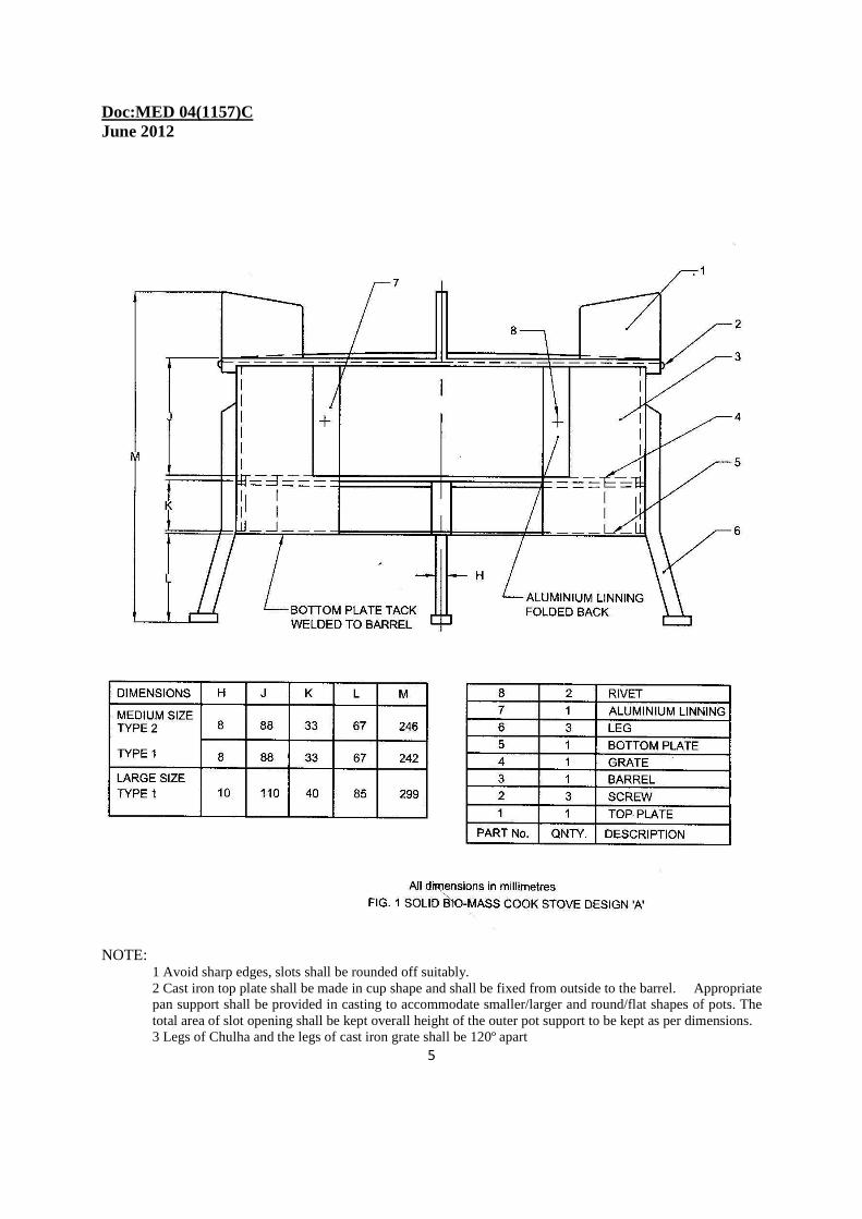
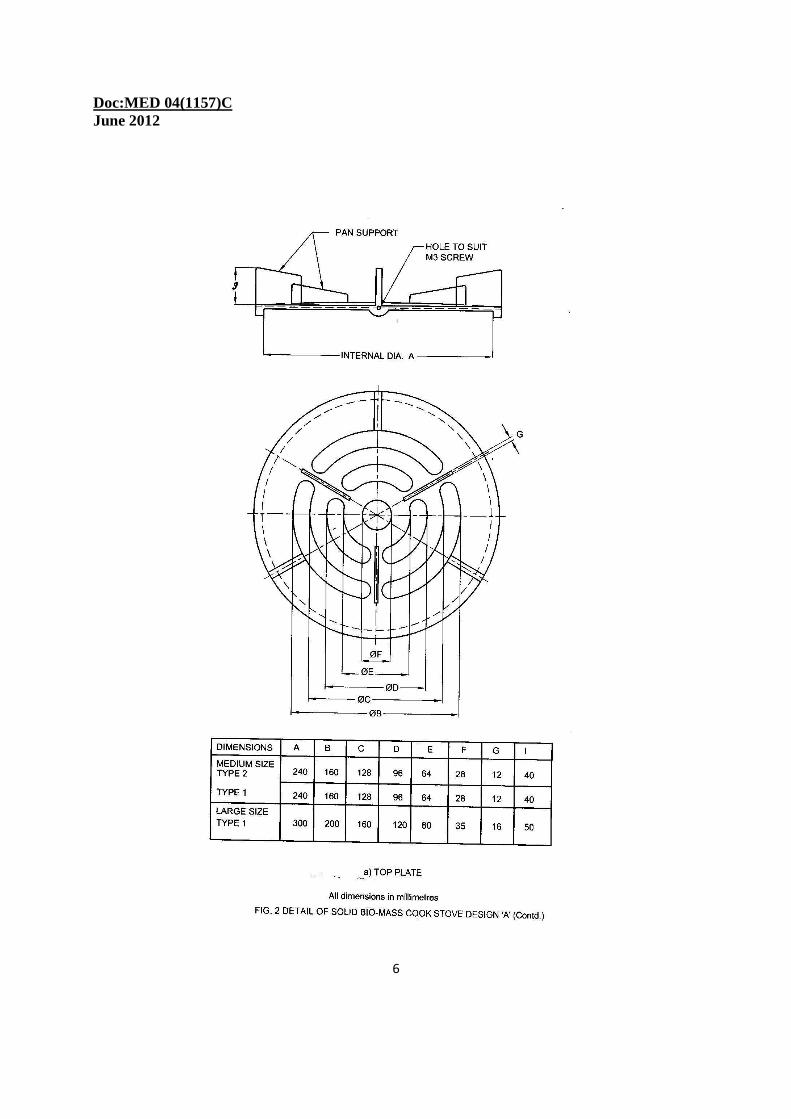
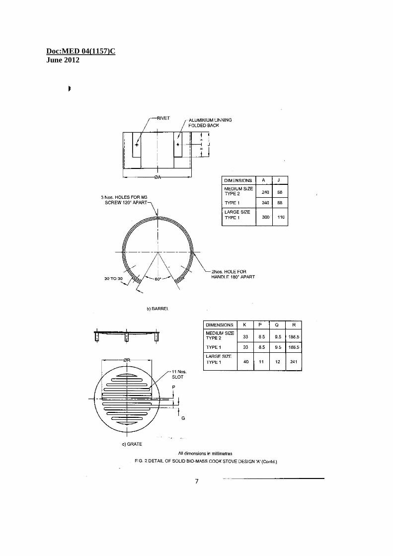
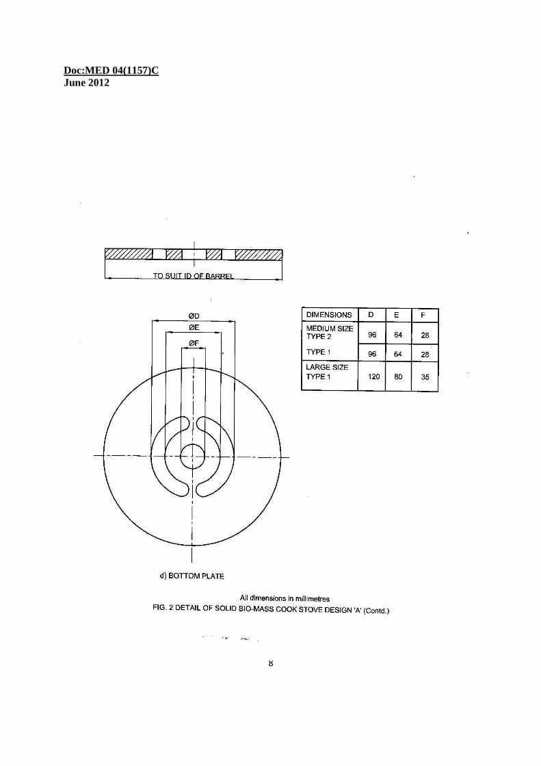
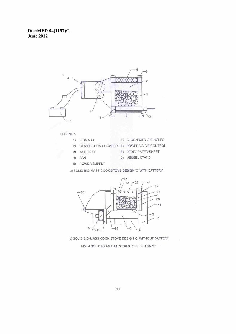
3 TERMINOLOGY For the purpose of this standard the nomenclature of different parts of the cookstove (chulha) shall be as given in Fig. 1 to Fig. 4.
Doc:MED 04(1157)C June 2012
3
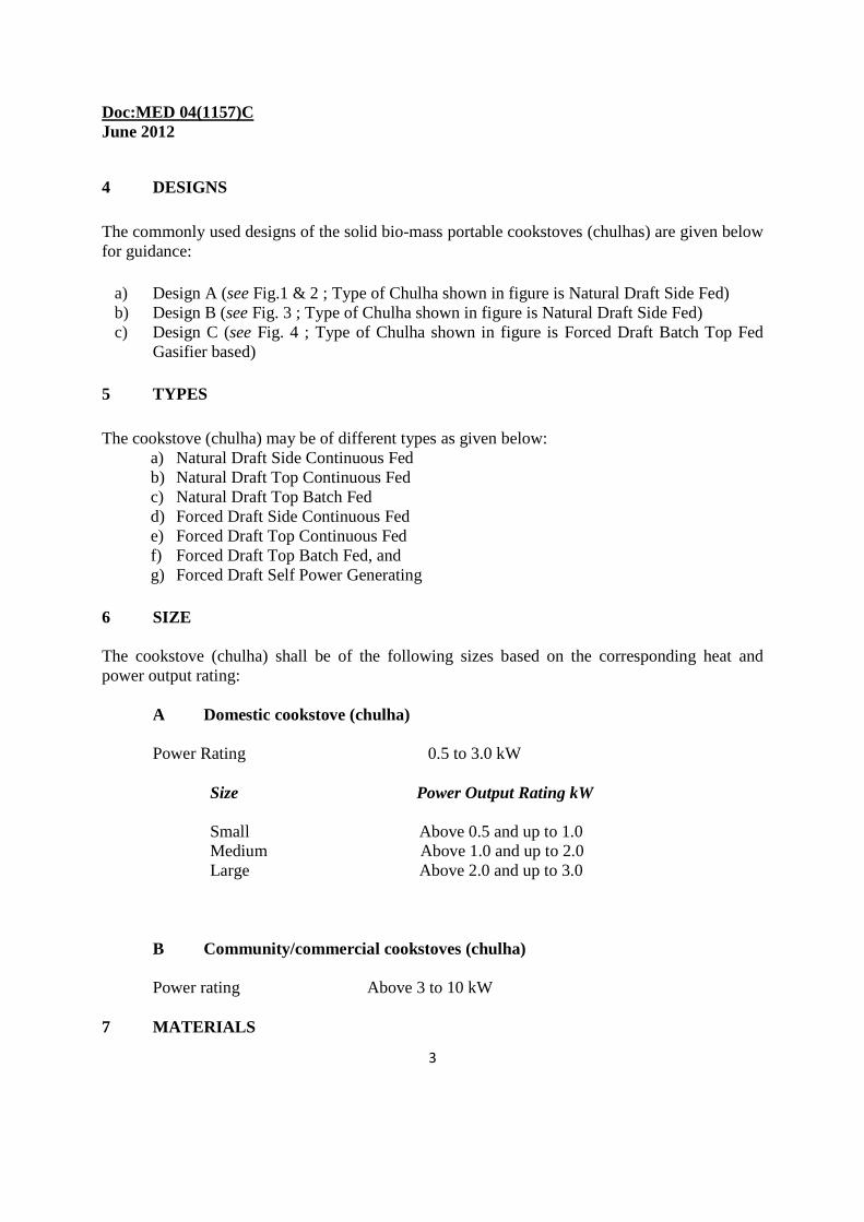
4 DESIGNS The commonly used designs of the solid bio-mass portable cookstoves (chulhas) are given below for guidance:
a) Design A (see Fig.1 & 2 ; Type of Chulha shown in figure is Natural Draft Side Fed) b) Design B (see Fig. 3 ; Type of Chulha shown in figure is Natural Draft Side Fed) c) Design C (see Fig. 4 ; Type of Chulha shown in figure is Forced Draft Batch Top Fed
Gasifier based) 5 TYPES The cookstove (chulha) may be of different types as given below:
a) Natural Draft Side Continuous Fed b) Natural Draft Top Continuous Fed c) Natural Draft Top Batch Fed d) Forced Draft Side Continuous Fed e) Forced Draft Top Continuous Fed f) Forced Draft Top Batch Fed, and g) Forced Draft Self Power Generating
6 SIZE The cookstove (chulha) shall be of the following sizes based on the corresponding heat and power output rating:
A Domestic cookstove (chulha)
Power Rating 0.5 to 3.0 kW
Size Power Output Rating kW
Small Above 0.5 and up to 1.0 Medium Above 1.0 and up to 2.0 Large Above 2.0 and up to 3.0
B Community/commercial cookstoves (chulha)
Power rating Above 3 to 10 kW 7 MATERIALS
Doc:MED 04(1157)C June 2012
4
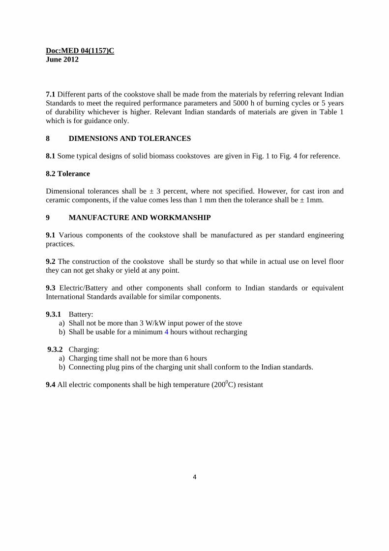
7.1 Different parts of the cookstove shall be made from the materials by referring relevant Indian Standards to meet the required performance parameters and 5000 h of burning cycles or 5 years of durability whichever is higher. Relevant Indian standards of materials are given in Table 1 which is for guidance only. 8 DIMENSIONS AND TOLERANCES 8.1 Some typical designs of solid biomass cookstoves are given in Fig. 1 to Fig. 4 for reference. 8.2 Tolerance Dimensional tolerances shall be ± 3 percent, where not specified. However, for cast iron and ceramic components, if the value comes less than 1 mm then the tolerance shall be ± 1mm. 9 MANUFACTURE AND WORKMANSHIP 9.1 Various components of the cookstove shall be manufactured as per standard engineering practices. 9.2 The construction of the cookstove shall be sturdy so that while in actual use on level floor they can not get shaky or yield at any point. 9.3 Electric/Battery and other components shall conform to Indian standards or equivalent International Standards available for similar components. 9.3.1 Battery:
a) Shall not be more than 3 W/kW input power of the stove b) Shall be usable for a minimum 4 hours without recharging
9.3.2 Charging:
a) Charging time shall not be more than 6 hours b) Connecting plug pins of the charging unit shall conform to the Indian standards.
9.4 All electric components shall be high temperature (2000C) resistant
Doc:MED 04(1157)C June 2012
5
NOTE:
1 Avoid sharp edges, slots shall be rounded off suitably. 2 Cast iron top plate shall be made in cup shape and shall be fixed from outside to the barrel. Appropriate pan support shall be provided in casting to accommodate smaller/larger and round/flat shapes of pots. The total area of slot opening shall be kept overall height of the outer pot support to be kept as per dimensions. 3 Legs of Chulha and the legs of cast iron grate shall be 120º apart
Doc:MED 04(1157)C June 2012
6
Doc:MED 04(1157)C June 2012
7
Doc:MED 04(1157)C June 2012
8
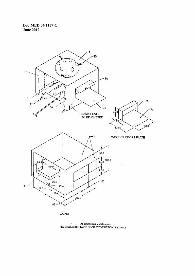
Doc:MED 04(1157)C June 2012
9
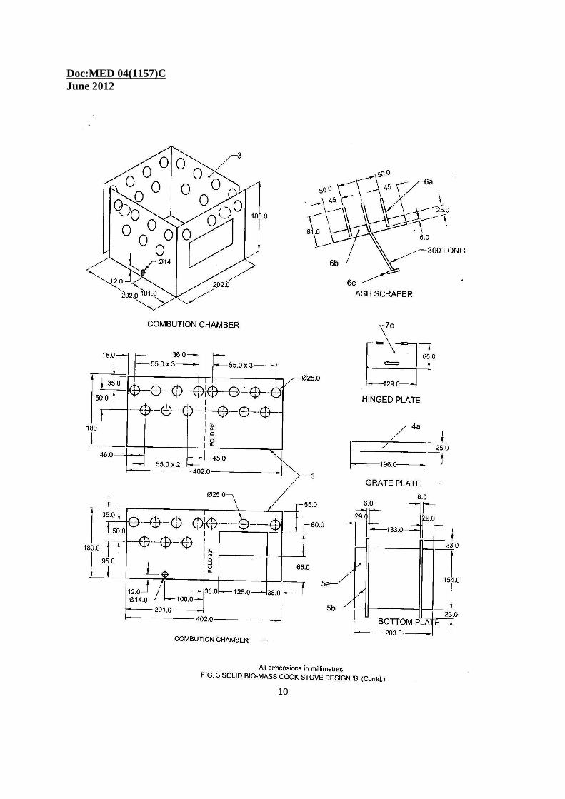
Doc:MED 04(1157)C June 2012
10
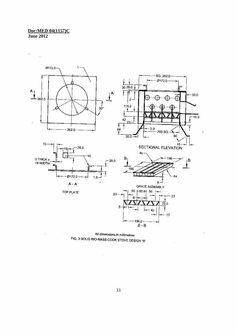
Doc:MED 04(1157)C June 2012
11
Doc:MED 04(1157)C June 2012
12
Nomenclature for Fig 3:
PART NO. DESCRIPTION No. reqd THICKNESS mm 10 VESSEL SUPPORT 3 3 x 19 FLAT 9 HANDLE (INSULATED) 2 3 x 19 FLAT 8 LEG 4 3 x 19 FLAT 7c HINGED PLATE 1 1 7b PLATE 1 1 7c WOOD SUPPORT PLATE 1 1.6 6c ROD(FOR ASH SCRAPER) 1 Ø 6 6b PLATE 1 2 6d ASH SCRAPPER FINGER 3 Ø 6 5b ROD 2 Ø 6 5d BOTTOM PLATE 1 1 4b ROD 4 Ø 6 4d GRATE PLATE 8 3 4 GRATE 1 3 3 COMBUSTION CHAMBER 1 1.6 2 JACKET 1 1 1 TOP PLATE 1 1.6
NOTE – 1. ALL DIMENSIONS ARE IN mm 2. APRROX WEIGHT OF FINISHED CHULHA: 5.7 kg 3. SCALE: NOT TO SCALE 4. MATERIAL:MILD STEEL (M.S) 5. ASH SCRAPER TO BE PROVIDED IN RIGHT SIDE OF CHULA 6. WELDING: MINIMUM FILLET:3.5mm, LENGTH: 6mm
DISTANCE BETWEEEN WELDING SPOTS:40mm 7. HANDLES SHALL BE INSULATED 8. POWER OUTPUT RATE: WOOD = 1.5 kW/Hr, DUNGCAKE = 1.65 kW/Hr
Doc:MED 04(1157)C June 2012
13
Doc:MED 04(1157)C June 2012
14
Nomenclature for Fig 4(b):
Part No. Description
1. Fuel 2. Air flow chamber 3. Variable height grate 4. Combustion Chamber 5. Outer chamber 5a Outer chamber with annular space 6. Ash removal tray 7. Stove 8. Fan 9. Rechargeable battery 10. Secondary air Valve 11. Primary air Valve 12. Air manifold or annular chamber 13. Secondary Air holes 14. Regulator 15 Duct 18 Top of the chamber 20 Potentiometer 21 Ceramic block Insulation 25. Top plate with a central hole 26. Vessel support 30 Stove Stand 31 Outer container 51 Ash tray handle
Doc:MED 04(1157)C June 2012
15
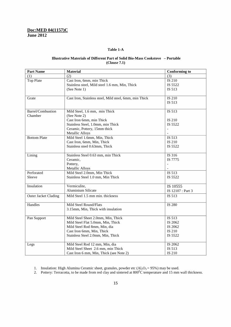
Table 1-A
Illustrative Materials of Different Part of Solid Bio-Mass Cookstove – Portable (Clause 7.1)
Part Name Material Conforming to (1) (2) (3) Top Plate Cast Iron, 6mm, min Thick
Stainless steel, Mild steel 1.6 mm, Min, Thick (See Note 1)
IS 210 IS 5522 IS 513
Grate Cast Iron, Stainless steel, Mild steel, 6mm, min Thick IS 210 IS 513
Barrel/Combustion Chamber
Mild Steel, 1.6 mm, min Thick (See Note 2) Cast Iron 6mm, min Thick Stainless Steel, 1.0mm, min Thick Ceramic, Pottery, 15mm thick Metallic Alloys
IS 513 IS 210 IS 5522 - -
Bottom Plate Mild Steel 1.6mm, Min, Thick Cast Iron, 6mm, Min, Thick Stainless steel 0.63mm, Thick
IS 513 IS 210 IS 5522
Lining Stainless Steel 0.63 mm, min Thick Ceramic, Pottery, Metallic Alloys
IS 316 IS 7775 - -
Perforated Sleeve
Mild Steel 2.0mm, Min Thick Stainless Steel 1.0 mm, Min Thick
IS 513 IS 5522
Insulation Vermiculite, Aluminium Silicate
IS 10555 IS 12107 : Part 3
Outer Jacket Clading Mild Steel 1.5 mm min. thickness IS 513
Handles Mild Steel Round/Flats 3.15mm, Min, Thick with insulation
IS 280
Pan Support Mild Steel Sheet 2.0mm, Min, Thick Mild Steel Flat 5.0mm, Min, Thick Mild Steel Rod 8mm, Min, dia Cast Iron 6mm, Min, Thick Stainless Steel 2.0mm, Min, Thick
IS 513 IS 2062 IS 2062 IS 210 IS 5522
Legs Mild Steel Rod 12 mm, Min, dia Mild Steel Sheet 2.6 mm, min Thick Cast Iron 6 mm, Min, Thick (see Note 2)
IS 2062 IS 513 IS 210
1. Insulation: High Alumina Ceramic sheet, granules, powder etc (Al2O3 = 95%) may be used. 2. Pottery: Terracotta, to be made from red clay and sintered at 8000C temperature and 15 mm wall thickness.
Doc:MED 04(1157)C June 2012
16
NOTE:
1 The thickness of the material used for different component of community/commercial chulhas are to be higher for providing adequate strength and life.
2 The legs of cast iron shall be made by extending the barrel to form legs.
10. MARKING 10.1 Each Cookstove shall be marked by stamping with the following information:
a) Serial number and date of manufacture b) Model Name c)Type, Input and output Power ratings with specifications of all component and accessories d) Weight of the Cookstove e) Name and address of the manufacturer, and f) Mention best performance for Fuel type, size and feeding rate and igniting procedure in the manual to be supplied with the Cookstove.
10.2 Identification of the source of manufacture of the Cookstove shall be affixed on all the detachable and cast iron components. 10.3 Each Cookstove may be marked with the Standard Mark. 10.3.1 The use of the Standard Mark is governed by the provisions of the Bureau of Indian Standards Act, 1986 and the Rules and Regulations made thereunder. The details of conditions under which a license for the use of the Standard Mark may be granted to the manufacturers or producers may be obtained from the Bureau of Indian Standards. 11. PERFORMANCE TEST 11.1 Thermal Efficiency Test Thermal efficiency for each Cookstove when tested in accordance with the method described in Annex A shall not be less than 25 percent for all types of designs and sizes of solid bio-mass natural draft Cookstove. For forced draft types it shall not be less 35 percent. 11.2 Emission Test 11.2.1 CO/C02 Ratio When tested in accordance with the method described in B-1 the carbon monoxide/carbon dioxide ratio of exhaust gases of chulha, while burning at optimum output ( CO/C02) shall not
Doc:MED 04(1157)C June 2012
17
exceed 0.04 for natural draft. For forced draft it shall not exceed 0.02. The test report shall also mention absolute values of CO and CO2 during the test period. 11.2.2 Total Suspended Particulate when tested in accordance with the method described in B-2, the total suspended particulate shall not exceed 2.0 mg/m3 based on Light Scattering Techniques. PM 10 and PM 2.5 may also be measured using Isokinetic Sampling Procedure to quantify the finer particles of size less than 2.5 micron as per the method given in Annex - B. The test report shall also mention absolute value of Total Suspended Particulate Matter and PM 2.5 in mg/kg of fuel consumed. 11.3 Surface Temperature Test Surfaces which in normal use have to be touched for short periods (for example, handles, etc ) shall not have a temperature exceeding 60°C when measured in accordance with Annex C. The temperature of synthetic rubber/plastic components, if used, shall also not exceed 60°C. 11.4 Quenching Test of Cast Iron Components When tested in accordance with the method described in Annex D, the grate, top plate and any other cast iron component shall withstand the test without any crack or deformity. 11.5 Stability Test Cookstove both when full of fuel and when empty, shall be capable of being tilted in any direction to an angle of 15° from the vertical, without overturning at that inclination or on being released. 11.6 Electric Appliances Test Blowers, condensers/storage battery, wires, plugs, thermopile shall be as per Indian Standards mentioned below: IS 12292, IS 941, IS 7358, IS 1293, IS 302 (Part 1) ,IS 302, (Part 2 : Sec 6), IS 302 (Part 2 : Sec 202)
Doc:MED 04(1157)C June 2012
18
ANNEX A (Clause 11.1)
TEST FOR THERMAL EFFICIENCY A-1 THERMAL EFFICIENCY A-1 Thermal efficiency of a Cookstove may be defined as the ratio of heat actually utilized to the heat theoretically produced by complete combustion of a given quantity of fuel (which is based on the net calorific value of the fuel). A-2 CONDITIONS FOR CARRYING OUT THERMAL EFFICIENCY TEST A-2.1 Test Conditions A-2.1.1 For carrying out thermal efficiency and emission test, the solid biomass Cookstove shall be kept in a standard fume hood having following illustrative specifications. Fume Hood dimensions: 1000mm W × 750mm D × 1500mm H A-2.1.2 The air of the test room housing the fume hood shall be free from draught likely to affect the performance of the Cookstove . The room temperature shall be maintained at 25±5°C using systems as may be necessary. A-2.1.3 At the start of the test, the Cookstove and the wood being used shall be at room temperature. A-3 EQUIPMENT A-3.1 Instruments and other Accessories
a) Digital Bomb calorimeter with Printer. b) Mercury in glass thermometers (range 0-100°C) [see IS 2480 (Part 1):1983] with solid stem/other temperature measuring device like thermocouples with the accuracy of ± 0.1 °C . Devices for higher range of temperature, say 0-1300oC to measure the flame temperature. c) Digital balance 15 kg capacity (dial type/digital with least count of 1 g) to weigh the fuel. Higher capacity balance of 10 gm to weigh the Cookstove, the water in vessels etc depending upon size of the Cookstove to be tested. d) Measuring jars; 2 l and 5 l capacity. e) Digital Stop watch with memory or time measuring device. f) Pairs of tong, metallic tray, high temperature gloves, matches, etc.
Doc:MED 04(1157)C June 2012
19
g) Pieces of clean cloth. h) Moisture Meter with microwave or infrared heating facility i) Vessels for holding water to be placed on the Cookstove for heating as per Table 2.
A-3.2 Fuel and its preparation The fuel shall be wood like Kail/Deodar/Mango/Accasia cut from the same log into pieces of 3 cm × 3 cm square cross-section and length of half the diameter/length of combustion chamber so as to be housed inside the combustion chamber or the briquettes/pellets/loose bio-mass as specified by the Cookstove manufacturer. The fuel shall be dried by the following method:
a) Weigh total quantity of fuel (say 'M' kg) b) Pick up one piece/pouch of fuel and mark 'X' and take its mass (say 'm' g), c) Raise the temperature of electric oven up to 105°C, d) Stack the fuel in a honey comb fashion and in case of loose biomass spread it to a 10 mm thickness in a tray and put inside the fuel oven, e) Maintain the oven temperature at 105°C, f) After 6 h, remove the marked 'X' piece/pouch, weigh it and note reduction in mass from 'm' g, if any. If reduction is observed put the marked piece/pouch in the oven again and repeat the weighing of 'X' marked piece/pouch after every subsequent 6 hours durations till the mass is constant and no further reduction in mass is observed. g) At this, weigh the total quantity of fuel and note loss of mass from 'M' kg. h) Determine the moisture content of the fuel so dried using a microwave/infrared heated moisture meter and the value shall not exceed 10 percent, and i) Determine the calorific value of the prepared fuel with the help of digital bomb calorimeter.
A-3.3 Determination of Burning Capacity Rate If the fuel burning rate is not given by the manufacturer, the method described below shall be used to estimate the burning capacity of the Cookstove.
Doc:MED 04(1157)C June 2012
20
A-3.3.1 Stack the combustion chamber with test fuel as given in A-3.2 upto 1/2 of the height for continuous feeding type Cookstove, or in a pattern recommended by the manufacturer. A-3.3.2 Place a pot over the Cookstove. The pot shall be half filled with water and having bottom diameter 1.5 times the pot opening of the Cookstove. A-3.3.3 Sprinkle 10 to 15 ml of kerosene on the fuel from the top of Cookstove /fire box mouth . A-3.3.4 Weigh the Cookstove with fuel, let the mass be M1 kg. A-3.3.5 After half an hour of lighting weigh the chulha with fuel residues again and let the mass be M2 kg. A-3.3.6 Then calculate the burning capacity of the Cookstove as heat input per hour as follows:
Heat input per hour = 2 ( M1 – M2) × CV kcal/h where
M1 = the initial mass of the Cookstove with test fuel in kg, M2 = the mass of the Cookstove with fuel residues, after burning the test fuel for half an hour in kg, and CV = Calorific value of the test fuel in kcal/kg.
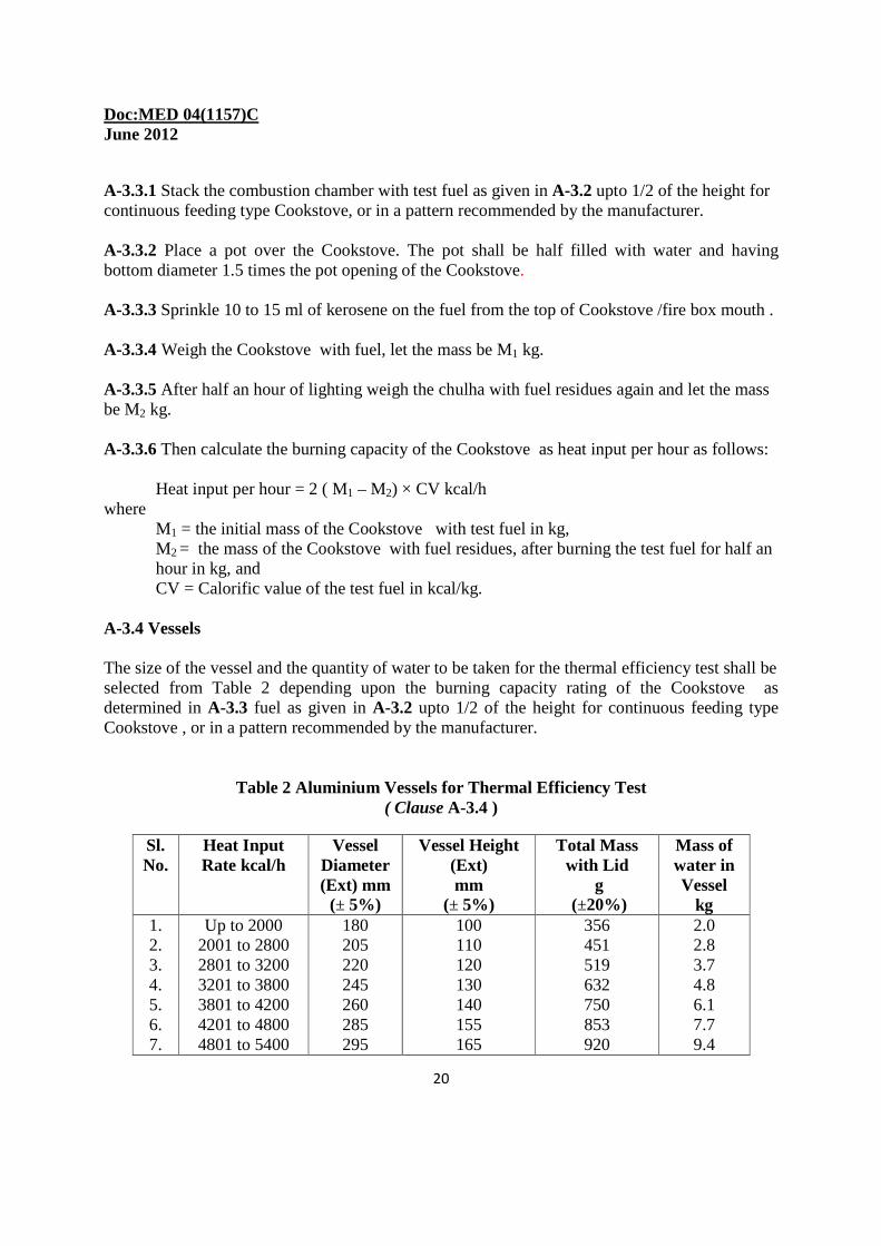
A-3.4 Vessels The size of the vessel and the quantity of water to be taken for the thermal efficiency test shall be selected from Table 2 depending upon the burning capacity rating of the Cookstove as determined in A-3.3 fuel as given in A-3.2 upto 1/2 of the height for continuous feeding type Cookstove , or in a pattern recommended by the manufacturer.
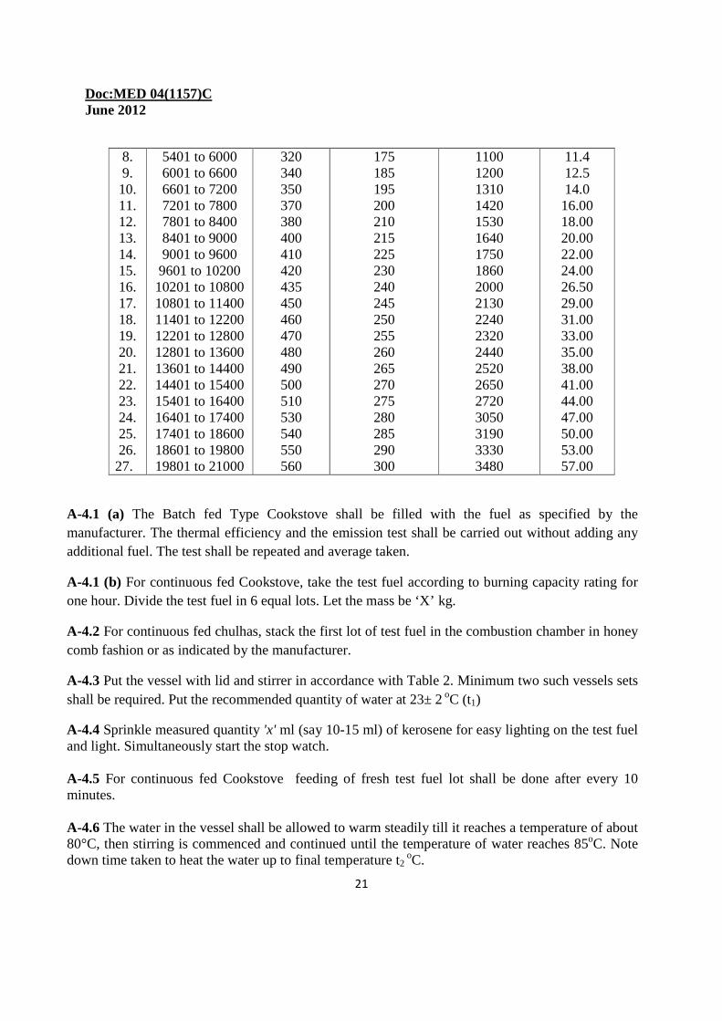
Table 2 Aluminium Vessels for Thermal Efficiency Test ( Clause A-3.4 )
Sl. No.
Heat Input Rate kcal/h
Vessel Diameter (Ext) mm (± 5%)
Vessel Height (Ext) mm
(± 5%)
Total Mass with Lid
g (±20%)
Mass of water in Vessel
kg 1. 2. 3. 4. 5. 6. 7.
Up to 2000 2001 to 2800 2801 to 3200 3201 to 3800 3801 to 4200 4201 to 4800 4801 to 5400
180 205 220 245 260 285 295
100 110 120 130 140 155 165
356 451 519 632 750 853 920
2.0 2.8 3.7 4.8 6.1 7.7 9.4
Doc:MED 04(1157)C June 2012
21
8. 9. 10. 11. 12. 13. 14. 15. 16. 17. 18. 19. 20. 21. 22. 23. 24. 25. 26. 27.
5401 to 6000 6001 to 6600 6601 to 7200 7201 to 7800 7801 to 8400 8401 to 9000 9001 to 9600 9601 to 10200 10201 to 10800 10801 to 11400 11401 to 12200 12201 to 12800 12801 to 13600 13601 to 14400 14401 to 15400 15401 to 16400 16401 to 17400 17401 to 18600 18601 to 19800 19801 to 21000
320 340 350 370 380 400 410 420 435 450 460 470 480 490 500 510 530 540 550 560
175 185 195 200 210 215 225 230 240 245 250 255 260 265 270 275 280 285 290 300
1100 1200 1310 1420 1530 1640 1750 1860 2000 2130 2240 2320 2440 2520 2650 2720 3050 3190 3330 3480
11.4 12.5 14.0 16.00 18.00 20.00 22.00 24.00 26.50 29.00 31.00 33.00 35.00 38.00 41.00 44.00 47.00 50.00 53.00 57.00
A-4.1 (a) The Batch fed Type Cookstove shall be filled with the fuel as specified by the manufacturer. The thermal efficiency and the emission test shall be carried out without adding any additional fuel. The test shall be repeated and average taken.
A-4.1 (b) For continuous fed Cookstove, take the test fuel according to burning capacity rating for one hour. Divide the test fuel in 6 equal lots. Let the mass be ‘X’ kg.
A-4.2 For continuous fed chulhas, stack the first lot of test fuel in the combustion chamber in honey comb fashion or as indicated by the manufacturer.
A-4.3 Put the vessel with lid and stirrer in accordance with Table 2. Minimum two such vessels sets shall be required. Put the recommended quantity of water at 23± 2 oC (t1)
A-4.4 Sprinkle measured quantity 'x' ml (say 10-15 ml) of kerosene for easy lighting on the test fuel and light. Simultaneously start the stop watch. A-4.5 For continuous fed Cookstove feeding of fresh test fuel lot shall be done after every 10 minutes. A-4.6 The water in the vessel shall be allowed to warm steadily till it reaches a temperature of about 80°C, then stirring is commenced and continued until the temperature of water reaches 85oC. Note down time taken to heat the water up to final temperature t2
oC.
Doc:MED 04(1157)C June 2012
22
A-4.7 Remove the vessel of A-4.6 from the Cookstove and put the second vessel immediately on the Cookstove . Prepare first vessel for subsequent heating. A-4.8 Repeat the experiment by alternatively putting the two or more vessels taken in A-4.3 till there is no visible flame in the combustion chamber of the Cookstove. Note down the temperature of the water in the last vessel. Let it be t3 ºC. A-5 CALCULATION A-5.1 Thermal efficiency of the cook stove shall be calculated as follows. A-5.1.1 Notations and formulae
w = mass of water in vessel, in kg. W = mass of vessel complete with lid and stirrer, in kg. X fuel = mass of solid fuel consumed, in kg Hfuel = calorific value of wood (or solid fuel), in kJ/kg Xk = mass of kerosene used for ignition (kg) Hk = calorific value of kerosene, in kJ/kg t1 = initial temperature of water in °C t2 = final temperature of water in °C t3 = final temperature of water in last vessel at the completion of test in °C n = total no vessel used Cw = specific heat of water (= 4.12kJ/kg/°C) Cv = specific heat of the material of the vessel (aluminium) (=0.896kJ/kg/°C) Hout = heat output of the stove (heat utilized ) in kJ Hin = heat input into the stove (heat produced) in kJ η = thermal efficiency in percent
Hout = [(n–1) × (W × Cv + w × Cw) × (t2-t1)] + [(W × Cv+ w × Cw) × (t3–t1)] Hin = (Xfuel × Hfuel) + (Xk × Hk) η = 100 × Hout/Hin A-5.2 Power Output Rating The power output rating of chulha is a measure of total useful energy produced during one hour by fuel wood, It shall be calculated as follows:
Power output rating, Po = F × Hfuel × η / 360000 kW Where, Po = Power output
F = rate of consumption of fuel wood (kg/h) Hfuel = calorific value of wood (or solid fuel), in kJ/kg
η = thermal efficiency of the chulha in percent .
Doc:MED 04(1157)C June 2012
23
ANNEX B (Clause 11.2)
TEST FOR EMMISSION
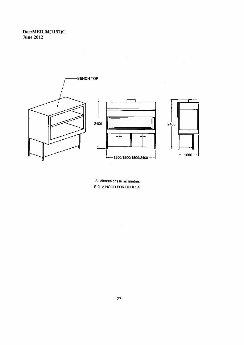
B-1 CO/CO2 RATIO MEASUREMENT B-1.1 Equipment B-1.1.1 The Cookstove shall be tested for its emissions simultaneously along with the testing of thermal efficiency by using stack monitoring, multi component gas analyzer, Non-Dispersive Intra-Red(NDIR) based detector system connected on line for continuous measurement of CO and CO2. In addition oxygen (O2) and other hydrocarbons could also be measured if so required by installing/ adding appropriate monitors for the same. The preferable range of measurement recommended at 0 to 10000 ppm with resolution of 1 ppm for CO, 0 TO 20 vol percent resolution of 10 ppm for CO2, 0 to 20 vol percent with resolution of 100 ppm for O2. The multi component gas analyzer must be fitted with a sample conditioning unit to control/ regulate the conditions like humidity, temperature, pressure, flow rate, moisture, dust, etc. of the sample for proper measurement. The Cookstove shall be placed in a collecting hood (see Fig.5) suitable for Cookstove under examination. B-1.1.2 The hood shall be such that, it collects all the flue gases without interfering in any way with the normal combustion of the Cookstove . The hood shall be closed on all sides except the front which carries a vertical rising counter balance sash (shutter), transparent and made of toughened float glass (6 mm thick) to facilitate smooth operation. The clear openable height of sash could be 750mm to allow Cookstove to move in and out of the hood easily. However, it should be possible to open the sash to any desired height to minimize the effect of unfiltered air entering the hood when fire needs tending. The effect of the enclosed hood is to ensure slight negative pressure in the hood at all times, thus no emissions can leave the hood. The air is pulled through the fume hood by a constant volume pump. The speed is controlled by a variable frequency drive (VFD). The actual amount of air pulled by the fan depends on the density of the air, which is affected by the temperature and pressure. To accurately calculate the mass of air moved, the temperature (using K type thermocouple) and pressure (using pressure transducer) are taken at the entrance to the blower. The hood shall be fitted with the emission measurement systems such that the sample collected represents the whole of combustion gases and not those from one particular point. This can be best done by drawing the sample for emission measurements from the top of the hood where it is connected with a smaller diameter exhaust pipe. A stainless steel sample probe, inserted perpendicular to the gas flow, is used to sample gas emissions. The probe is constructed as per standard method. Also standard methods are used to determine the proper location of the sample probe in the flow of gases with in the pipe. The probe is placed five pipe diameters downstream of any flow disturbances. Heated (PTFE and/ or stainless steel) sample lines are used to transport the sample from the probe to the NDIR Analyser. The basic sampling units provides the pump, filters, thermo electric cooler, flowmeters and other components required to clean, dry and regulate the flow of sample gas to the analyser module.
Doc:MED 04(1157)C June 2012
24
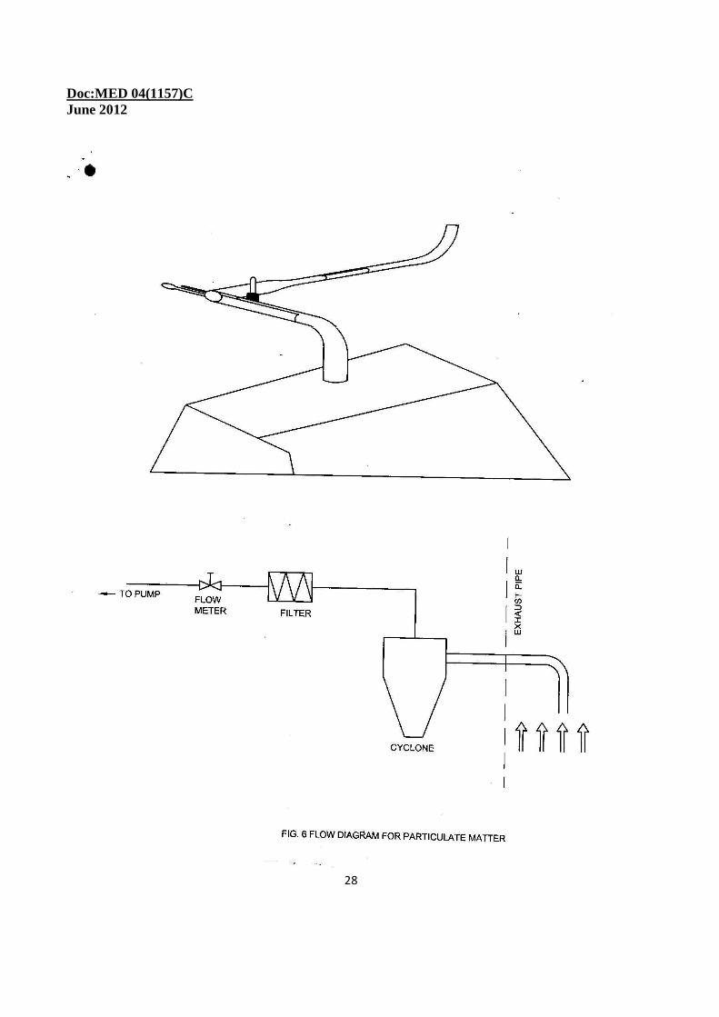
NOTE: Or otherwise, downstream of chimney of the hood shall be provided with hotwire anemometer to measure the flow of exhaust gas. B-1.2 Procedure B-1.2.1 With the hood in position and the Cookstove under Investigation placed inside the hood, the procedure as given in A-4.1 to A-4.8 shall be followed and a continuous measurement of CO, CO2 and O2 samples shall be carried out. B-1.2.2 Non Dispersive Infrared (NDIR) sensor module using dual beam non dispersive infrared absorption method for CO and CO2 and Magnetic-pneumatic analysis method for O2 shall be followed to measure these gases. B.2 TEST FOR PARTlCULATE MATTER (PM) B-2.1 Equipment B-2.1.1 For particulate matter emission measurement the following methods (fig. 6) are used: (i) real-time measurement of a particulate matter via light scattering, and (ii) gravimetric measurement with cyclone for 2.5 micron cutoff. For real-time measurement of a particulate matter via light scattering, an optical instrument is used to measure the concentration of dust or particulate matter suspended in exhaust gas passing through a duct, stack, or flue- typically the exhaust gas from combustion processes. The reduction in intensity is calibrated to measure the particulate concentration in mg/m3. The gravimetric measurement equipment consist of a cyclone for 2.5 micron cutoff and an s-type pitot. This pitot tube is attached to a digital pressure transducer, which in conjunction with the thermocouple, can be used to calculate the velocity of the exhaust. The velocity measurement is used to calculate the rate at which sample pumps shall pull sample gas through the probes to ensure that there is no change in velocity from the duct to the sample port. Ports are welded into the exhaust pipe allowing two 35.56 cm (14 inch) straight stainless steel probes to be inserted into the flow. The tubes used are 6.35 mm (¼ inch) outer diameter stainless steel seamless tubing with a 20º chamfer on the leading edge. This chamfer is added to limit disrupting the flow as much as possible. The filter pack is a stainless steel housing holding two filter cassettes connected directly to the outlet of the sample probe. One cassette is the second stage of the housing to ensure a tight seal while the front cassette is loaded with a PTFE filter (47mm diameter 2µm pore size). Housing runs from the outlet of the filter back to the mass flow controller and then to the vacuum pump. B-2.2 Method for Particulate Sampling The samples need to be taken iso‐mass‐velocity condition (also called isokinetic sampling). To ensure iso‐mass‐velocity, a large diameter (127mm), long‐radius duct is used to decrease the exhaust velocity and the turbulence magnitude. While the samples shall be taken in a slightly turbulent environment to ensure good mixing, too much turbulence can lead to impacting on the probe. To
Doc:MED 04(1157)C June 2012
25
ensure that the sample is adequately mixed, a Reynolds number greater than 5000 shall be maintained. B-2.3 Filter Weighing Procedure The PM filter weighing procedure is a multistep process. The filters must be allowed to equilibrate in the measurement lab for at least 2 hours before being weighed. This equilibration time, allows for the filters to come to a uniform temperature and humidity with their, surroundings. The measurement lab needs to remain at a constant relative humidity due to the fact that the filters will gain mass in a more humid environment which will register on the balance being used. Once the filters have equilibrated they are measured on a balance (1µg resolution). The same calibration weight is used before each series of measurements to ensure the balance is consistent from day to day. The filters are placed on a Polonium strip to discharge whatever static electric charge might have formed before being placed on the balance. Each filter is measured three times with the filter removed and balance doors closed between each measurement. Once the filter is weighed it is placed in a new Petri dish, marked with a filter ID number and the three measurements are recorded on a filter ID log sheet. Also on the log are the calibration weights mass and the temperature and relative humidity of the room. Once the filters have been used they are returned to the measurement lab where they are again allowed to equilibrate before the measurement process happens again. B -2.4 CONVERSION OF EMISSIONS FROM CONCENTRATION I N THE EXHAUST TO AMOUNT EMITTED PER UNIT MASS OF THE FUEL The NDIR module measures the “parts per million” (ppm) of various gaseous species. This ppm measurement must then be converted into the emission per unit mass of fuel burnt. The following nomenclature is used in this conversion: Ρ = Density of the exhaust gases (kg/m3) T = Temperature (K) P = Pressure (Pa) R = Gas Constant of air (=286.9J/(kg K)) D = Pump displacement (m3/rev) X i = Measured concentration of the pollutant constituent, i in ppm (mg/kg)
= Mass flow rate of exhaust gases (kg/s) V = Pump speed (RPM)
Doc:MED 04(1157)C June 2012
26
Ei = Emission of the pollutant, i, in mg/kg of fuel t = Sampling period Mf = Mass of fuel consumed during the sampling period. The density of each constituent in the exhaust is calculated using using ρ = P / (R × T) The mass flow of the entire exhaust is calculated using the following due to the high dilution rate. The flow rate of the exhaust is assumed to be essentially the same as that of air. = v × ρ × d / 60 The emission of each constituent is calculated using
Ei = × t × Xi / Mf
Doc:MED 04(1157)C June 2012
27
Doc:MED 04(1157)C June 2012
28
Doc:MED 04(1157)C June 2012
29
ANNEX C (Clause 11.3 )
METHOD OF MEASUREMENT OF SURFACE TEMPERATURE
C-1 PREPARATION OF CHULHA C-1.1 The Cookstove shall be operated at the full output for one hour before starting the measurement of temperature, with the vessel containing water placed over it. C-2 PROCEDURE C-2.1 The temperature of all parts of the Cookstove which may be necessary to touch during its operation shall be measured by using a thermometer or any other suitable device for measuring the surface temperature. The temperature of each such parts shall be measured thrice every 30 minutes until equilibrium is reached. While measuring the temperature the thermometer shall be covered with a felt pad, asbestos or aluminium foil and kept in contact with that part for sufficient foil and kept in contact with that part for sufficient period of time until the maximum temperature is reached.
ANNEX- D (Clause 11.4 )
PROCEDURE FOR QUENCHING TEST ON CAST IRON COMPONENT S OF PORTABLE CHULHA
D-1 PROCEDURE D-1.1 Before each quenching, Cookstove will be burnt for 45 minutes duration and the feeding of fuel would be done at the rate of 1/4th of the burning rate of fuel every 15 minutes. D-1.2 Quenching of grate and top plate only to be done. The top plate and grate will be de-linked from the Cookstove and put in water. D-1.3 Top plate and grate will be put in Water in separate vessels. D-1.4 Water will be changed after every immersion. D-1.5 Water to be taken shall be in the temperature range of 20oC to 30°C. D-1.6 Top plate and grate will be put in water in one stroke in horizontal position and submerged. D-1.7 Each vessel will contain 5 litres of water every time.
Doc:MED 04(1157)C June 2012
30
D-1.8 The cast iron components will be left in water for a duration of 10 minutes.
D-1.9 The cast iron components will be taken out of water after the duration given in D-1.8 and then wiped and examined for any possible cracks. D-1.10 The above process of heating and quenching shall constitute one cycle.
D-1.11 The above cycle shall be repeated for eight times first and further 2 times more (total 10 times). If there is no crack at the end of 10th cycle the sample may be considered to withstand the test. If a hairline crack develops at the end of eighth cycle and do not widen at the end of 10th cycle the part shall be further subjected to two more cycles and there shall be no further widening of the crack, otherwise the sample shall be considered not to withstand the test