division 1 right of way plans 1 right of way plans wsdot plans preparation manual m 22-31.04 page...
TRANSCRIPT
WSDOT Plans Preparation Manual M 22-31.06 Page 1-1 March 2018
Division 1 Right of Way Plans
100.01 Introduction 100.02 Vicinity Map (or Vicinity Map and Total Parcel Details) 100.03 Plan Sheets 100.04 Right of Way Acquisition Details 100.05 Sundry Site Plans 100.06 Parcel Acquisition Plans 100.07 Exhibit Maps 100.08 Access Report Plan 100.09 Access Hearing Plan 100.10 Special Right of Way Plans 100.11 Revisions to Approved Right of Way Plans 100.12 Access Control Notes 100.13 Archiving R/W Plans 100.14 Digital Signatures
100.01 Introduction Right of Way Plans are the official state documents used as the basis to acquire real estate and other property rights. All deeds or other instruments conveying land or interest in land to the state that are to be accepted at the Washington State Department of Transportation (WSDOT) Headquarters (HQ) must conform to the approved Right of Way Plan. The plans are referred to in legal instruments and are permanently filed for public record at the WSDOT Headquarters in Olympia.
It is the responsibility of the region to assemble data and prepare plans for the acquisition of rights of way (R/W), including easements, permits, and any substantiating documentation necessary for completion of the plans. Verification of ownership of existing R/W is also required.
To assemble the data, the region requests Assessor’s maps, county road maps, previous state highway base maps and last conveyances for use during early plan preparation. As soon as the parcels from which additional right of way will be acquired are identified, Title Reports with Assessor’s land areas are requested for use in completing the Right of Way Plans.
Early plan preparation includes the following:
• The Region Real Estate Services Manager is consulted to determine the degree of property interests to be acquired, such as fee title, easements, and temporary construction easements.
• The Region Right of Way Manager is consulted to determine whether existing plans are adequate for revisions or a new Right of Way Plan should be prepared.
• The Region Utilities Engineer is consulted to determine the extent of utility interests to be addressed.
Complete Right of Way Plans consist of a Vicinity Map and Right of Way Plan sheets. Right of Way Plans are to be prepared in English units only.
Right of Way Plans Division 1
Page 1-2 WSDOT Plans Preparation Manual M 22-31.06 March 2018
100.02 Vicinity Map and Total Parcel Details The Vicinity Map supplies general information depicting the project in relation to surrounding communities, public and private road networks, traffic movement patterns, and other local features. A total parcel detail and parcel number are included for any ownership too large to be shown on individual plan sheets (see Example 1-1).
A heavy line is used to indicate the new highway. Lighter lines in varying weights show interchanges, connecting road systems, bodies of water, and so on. Limited access, the existing right of way, and/or the proposed right of way are not shown. Detail and drafting requirements are set forth in the WSDOT Electronic Engineering Data Standards (EEDS) Manual (see Deliverables Sections 4, 7, 8, and Symbology 4).
100.03 Plan Sheets New base maps shall be prepared in their correct geographically coordinate location. It is recommended the design team use information from the Record of Survey or other reliable source to locate the base map in its Geographic Location. This will allow measurements within the sheet to be correct and for future use within WSDOT’s GIS program.
The sheets are to be single sheet per file. This allows the sheets to be signed and edited without affecting other sheets. It also allows multiple users to work within the project at the same time.
All submittals shall be placed in the appropriate ProjectWise folder structure per the WSDOT EEDS Deliverables 8.08(2). A link to the proposed revision shall be placed on the Cover Sheet for each submittal.
100.03(1) Alignment The R/W centerline, from which the right of way is to be legally described, is shown as a continuous solid line for the full length of the project, with its alignment data shown. Additional non-controlling centerlines are shown by a dashed line without alignment data.
It is preferable that the main line R/W centerline not have a letter designation (such as LR Line) unless there is more than one main line centerline. Therefore, the Highway Engineer’s station will also not have a letter designation.
The new centerline stationing must have ties, by station and/or bearing equations, to existing centerline stationing at the beginning and end of the new plan.
It is recommended that all new plans should replace existing spiral curves on the R/W centerline with a simple circular curve in conformance with current design standards. When new R/W is to be purchased, the R/W alignment will conform to the new simple curve. If additional R/W is not to be purchased, the existing R/W alignment will retain the original spiral curve. The new plan will reference the superseded spiral alignment (see Examples 1-9a and 1-9b). Prior to plan preparation, consultation with the HQ Right of Way Plans Section is advised.
100.03(2) Control Features Plan sheets must show government subdivision corners, platted subdivisions, donation land claims, state and national park/forest boundaries, and Indian reservations. Show stations where government subdivision lines intersect our highway centerline. Add a cross-reference note to the Monumentation Map or Record of Survey prepared for the project.
Division 1 Right of Way Plans
WSDOT Plans Preparation Manual M 22-31.06 Page 1-3 March 2018
100.03(3) Right of Way Details (a) Right of way lines are continuous. These lines are shown crossing city streets, county
roads, rivers, and railroads, and they must match adjoining projects. Where a first-time improvement is planned, the existing county road or city street rights of way are enclosed by a right of way line or turnback line and are identified for later conveyance to the appropriate agency.
Data must be supplied to describe the right of way for its entire length from a centerline or, if necessary, from a metes and bounds description. Any existing right of way line retained as an ultimate right of way line for the new project is tied to and described from the new centerline or by a metes and bounds description. Ties to a previous centerline are not acceptable (see Example 1-2). When the existing right of way line is to be retained as an ultimate right of way line and is offset from an existing spiral alignment, consideration should be given to buying, selling, or exchanging small pieces of land with the adjacent owner to eliminate this offset spiral right of way line. Right of way widths and centerline stations are shown at the beginning and end of each sheet, except if in a taper, and at all points of change in width of the right of way. No point shall be double-described (that is, by a metes and bounds description and a station and offset) or by stations and offsets from two centerlines. All dimensions and areas must be shown on the final Right of Way Plan.
(b) A turnback line is shown as that line between right of way needed for highway purposes and right of way that will be relinquished to others (see Example 1-2). Areas for relinquishment are areas the state acquires for the improvement or construction of roads that will not remain a part of the highway system. The plan must show the areas being relinquished in sufficient detail and accuracy to allow a legal description to be written for the conveyance instrument (for example, stations and offsets or metes and bounds).
(c) An easement is a permanent or long-term right to enter upon the property of another for a defined purpose. Easements involve perpetual or temporary rights, which are non-cancelable by the property owner during the term of the easement. For example, an easement is used when the state is to construct a facility that does not require ownership of fee title (such as slope or drainage), and the acquisition of an easement right will save the department substantial funds in acquisition costs. The type of easement is defined on the Right of Way Plan (such as drainage easement, slope easement, or temporary construction easement) and is described by stations and offsets or by metes and bounds. Each type of easement and the area for each specific type is included in the ownership block under the Easement column opposite the appropriate parcel number (see Example 1-2). Third-party easements, such as utility or ingress/egress easements, that cross a parcel for the benefit of others will be shown on the plan. State highways crossing state and federal lands, are generally acquired as an easement. To define the highway margins and to have a consistent right of way line, these areas are shown as if fee title is acquired. Other areas where this may be encountered may include railroad, large land owners and utility rights of way crossings.
Right of Way Plans Division 1
Page 1-4 WSDOT Plans Preparation Manual M 22-31.06 March 2018
(d) A permit is a temporary right to enter upon the property of another for a defined purpose. These rights are issued for a limited time period—usually expiring upon completion of construction. Permits do not encumber the owner’s property, are nontransferable, and are cancelable by the grantor. Construction permits are not shown on the Right of Way Plans.
(e) An airspace corridor is a three-dimensional corridor of a specific width and length between two elevations. Airspace corridors are acquired in fee, and all rights of ownership apply to them. An airspace corridor is usually used where the highway is on a structure or in a tunnel. The property lying under or above the corridor may be used for other purposes as long as there is no detrimental effect on the highway facility. When the highway is on a structure, the only property acquired in fee would be the area needed to support the footings of the structure.
(f) Many Right of Way Plans contain an extreme amount of detail and will assign a point number to a specific location. A line table is used to identify the station, offset, and sometimes the elevation of each point. A separate table should be used for each feature such as R/W acquisition, easements, and air space corridors with a unique number assigned to each point. Plans utilizing multiple tables should place all tables on a separate plan sheet. This will allow for future table revisions without interfering with plan sheet line work. Each table should include a description of the specific feature and each feature should be shown in a separate table (see Examples 1-16a –1-16e).
(g) Surplus property is property that was acquired as operating right of way but is no longer needed as such. A plan revision mapping the surplus property area is necessary prior to disposal. Property that was acquired for uses other than operating highway right of way and is no longer needed is also labeled as surplus property on the Right of Way Plan prior to disposal. Some examples of surplus property would be unneeded pit sites, quarry sites and maintenance sites. Right of Way Plans are not revised to show surplus properties until both the region and Headquarters have completed their Surplus Property Review. If federal funds were used for the acquisition of right of way or construction of the facility, Federal Highway Administration (FHWA) approval is required before a plan revision can be approved. Disposal of uneconomic remainders does not need a plan revision.
(h) Property required for rest areas, historical markers, park & ride lots, truck weighing stations, wetlands mitigation areas, storm water treatment areas, landscape areas, and aquifer protection areas (see Design Manual Chapter 1710) are shown on the applicable plan sheets. If these facilities are situated beyond the reasonable limits of the plan, the sites are shown on a Sundry Site Plan (see Section 100.05). Material and stockpile sites are not shown on Right of Way Plans unless they are adjacent to the right of way and are fully describable thereon. Otherwise, they are shown on the Right of Way Plan with a note cross referencing the Sundry Site Plan where they are described.
(i) An Inventory Control Number (ICN) may be added to the plan to identify long-term leases or easements (typically 20 years or longer) and surplus property. Refer to the Surplus Property Review package to determine whether a plan revision is necessary. If
Division 1 Right of Way Plans
WSDOT Plans Preparation Manual M 22-31.06 Page 1-5 March 2018
an ICN will be added to the plan, the plan revision will normally identify the parcel or easement limits, the IC number, and the area.
Most ICN plan revisions will be prepared by the HQ Right of Way Plans Section. HQ Right of Way Plans Section will coordinate the plan revision with the HQ and region Property Management sections.
100.03(4) Access Control Limited access hachures define control of access between a highway facility and all other abutting property (see Example 1-3). On the title block of the plan sheet, the HQ Access and Hearings Office specifies the type of control: full, partial, or modified. If a transition is made from one type to another, the title block on the affected plan sheet includes both types and the plan sheet is labeled at the transition station. Specific considerations are:
• If the route has been designated for access control by the Secretary of Transportation, access control must conform to the Design Manual (see Chapter 530) unless advance approval for a deviation is obtained from the Secretary.
• On federal-aid routes, changes in access features from those that have been approved by FHWA require concurrence from FHWA prior to WSDOT approval under Certification Acceptance procedures authorized by FHWA.
• Limited access hachures are not shown when crossing railroad operating property, grade intersections, crossroads, or interchanges (see Example 1-3).
• At separation structures where there is no access to the highway lanes, the hachures are continuous, and traffic movement is permitted over or under the structures by note (see Section 100.12).
• In areas of partial or modified access control, approaches are allowed, but the hachures are never omitted. Each approach is defined in the access approach schedule (see Example 1-6).
• Existing Limited Access Plans must be reviewed (deeds examined) for previously deeded access approaches.
• The limits of access control hachures are shown on all crossroads, frontage roads, and so on.
Non-highway use of right of way (such as parking, storage, or buildings) requires an airspace lease (see the Right of Way Manual). When requested by HQ Real Estate Services, the plan sheets will clearly delineate the limits and character of the multiple-use area.
On new plans, the access control hachures may, in very limited instances, be moved to a precisely dimensioned invisible line, with the area labeled for the specific use and a turnback line and relinquishment notes provided if necessary. This is known as “Floating Hachures.”
On existing plans where access rights have been acquired, or on new plans where circumstances dictate retention of departmental control of the multiple-use area, the access hachures are carried on the right of way line and the other usage is shown by an access note.
Access notes concerning routine maintenance of utilities within the highway right of way are added to the plan following approval of the pertinent franchise or permit.
Modifying existing approved Limited Access hachures on an approved plan will require either FHWA approval or approval from the HQ Access & Hearings Manager. Contact the HQ Access and Hearings Office to determine the appropriate process.
Right of Way Plans Division 1
Page 1-6 WSDOT Plans Preparation Manual M 22-31.06 March 2018
100.03(5) Access Approach Schedule The access approach schedule and the access control notes supply all the information necessary for the granting of private approaches, and should reflect the language intended.
The access approach schedule furnishes, in tabular form:
1. The name of the owner, utility, or agency.
2. The station or station limits left or right of centerline.
3. The type of approach, and any access notes added.
Duplication of 1 above can be avoided by adding columns 2 and 3 to the ownership block, thereby showing all data pertinent to one ownership on one line (see Example 1-6).
Approaches that are granted shall be shown in the access approach schedule only on the sheet on which the approach appears.
Parcel number is on the sheet where the parcel first appears.
100.03(6) Railroad Easement Details A longitudinal easement is acquired from a railroad company when adjacent highway requirements overlap railroad property. The easement line is labeled and drawn the same weight as the right of way line. At beginning and end of the easement, show the highway station with equivalent railroad station. Offset distances to the easement line are taken perpendicular to each centerline. Under certain conditions, it may be necessary to describe the easement using railroad stationing by a metes and bounds description.
The crossing by a highway over, under, or at the grade of railroad property is by a crossing easement. The highway station with an equivalent railroad station is shown at each corner of the crossing easement and at the intersection of the railroad centerline and the R/W centerline. Access hachures are not to be carried across the railroad tracks, but are usually shown along the highway-railroad right of way or easement lines. The easement is labeled as a crossing easement. Separate areas for each type of easement are shown in the ownership block (see Example 1-2).
100.03(7) Drawing Standards Right of Way Plans are to be prepared in CAD with US survey foot units only, in conformance with the WSDOT Electronic Engineering Data Standards (EEDS) Manual (M 3028). Right of Way Plan revisions will be submitted to WSDOT HQ Right of Way Plans Office and stored in ProjectWise (a file management software). CAD levels, colors, line weights, symbols, base and sheet deliverables are to conform to the standards shown in the EEDS Manual (M 3028). Right of Way Plans are prepared using ground dimensions.
The right of way Vicinity Map and plan sheets should include the following information, as applicable:
• Plans are to be oriented with the Highway Engineers’ stations, increasing from left to right on the main line and ramps. It is desirable for mileposts to run in the same direction as stationing. Beginning stations on ramps should start at 10+00. When existing surveys conflict with this procedure, the R/W line should be re-stationed as stated above if new plans are drawn.
• All centerlines that are used to describe right of way should have bearings and stationing. Note: Do not use station or bearing equations within a new Right of Way Plan alignment. However, station and/or bearing equations can be used at the beginning and/or end of a
Division 1 Right of Way Plans
WSDOT Plans Preparation Manual M 22-31.06 Page 1-7 March 2018
new Right of Way Plan. Centerline mileposts are treated in the same manner. Mile Post equations are shown only at the beginning and end of new alignment plans.
• Mileposts at the beginning and end of the plan. The total length of the plan is shown only on the first sheet of the Vicinity Map.
• Centerline stationing and destination arrows are shown at the beginning and end of each sheet. The destination arrow shall refer to the nearest town, city, highway junction, or other major feature. Do not start or end a new plan set at the centerline of intersecting roads.
• On plan sheets use 5-Station numbers, such as 10+00 and 15+00. On the Vicinity Map, use 10-Station numbers, such as 10+00 and 20+00. Place the numbers parallel to and above the centerline.
• Beginning and end of plan cross-references to current contiguous plans are placed close to the beginning or end of plan note.
• New plans superseding an existing plan, each plan sheet will have a note stating the stationing, sheet number, name, and approval date of the plan being superseded by the new plan (see Example 1-2).
• Names of all interchanges, highways, city streets, county roads, railroads, and bodies of water.
• Highway structures shown in their correct location, drawn to scale, and identified as overcrossing or undercrossing in relation to the main line traffic movement. (Is the highway crossing over a structure or running under a structure?)
• Traffic movement pattern indicated by arrows on centerline, with the appropriate numeral added for multiple lanes.
• Townships, Ranges, government subdivisions, and platted subdivisions right-reading with map and a north arrow for orientation purposes.
• Section and quarter-section numbers right-reading with north. Quarter-Quarter labeling is aligned with the bottom of the sheet.
• Corporate limit and county boundaries indicated with the name of the city placed on the city side of the corporate limit line (see Example 1-1).
• Parcel identification numbers and total ownership boundaries (see Section 100.04) of parcels too large to be shown on a plan sheet are shown on the vicinity map. An Ownership block is not placed on the Vicinity Map. In the ownership block, show the name of the vested owner and the name of any contract purchaser in parentheses behind the vested owner.
• Parcel identification number should be placed as nearly as practical in numerical order above the highway first and then below the highway (assuming the highway is running in an east – west direction). This allows users to find a parcel number on the sheet quickly.
• When using the centerline as a match line, always use the smaller number above the larger number (see Example 1-1).
• Ownership or property dots are shown around the total parcel or contiguous parcels having the same owner. This helps identify potential assessment, access and condemnation issues. These dots may be revised, as needed, when that particular parcel is affected by a revision.
Right of Way Plans Division 1
Page 1-8 WSDOT Plans Preparation Manual M 22-31.06 March 2018
• Major utility transmission rights of way and tower numbers (if applicable). Other utility distribution lines should not be shown unless replacement right of way is being purchased.
• Turnback lines labeled and areas identified for conveyance (relinquishment, certification, or transfer) to the appropriate agencies are identified.
• Stormwater Treatment Areas, Wetlands Mitigation Sites, and other mitigation facilities are not part of the operating right of way and are considered non-highway use areas. If these areas are located within city limits, the right of way line will encompass these areas so they are included within the right of way. Stormwater Treatment Areas within the county limits, the right of way line may include or exclude the Stormwater Treatment Areas, or mitigation sites.
• Scale: Vicinity Map, 1 inch to 500 feet; Plan Sheets, 1 inch to 50 feet, unless special approval for a deviation is obtained from the HQ Right of Way Plans Manager.
• All public land identified by the agency name (for example, Snoqualmie National Forest) and a parcel number—except that WSDOT land is identified as WSDOT only.
• Grade intersection stations for all county roads. City street intersections are not labeled. Label includes centerline station equation and whether the intersection is left, right or both. A county road label designation is also included if improvement activities are being administered. (See Example 1-3)
• Basis of Bearings note should be included on all new Right of Way Plan sheets. Information included in the Basis of Bearings description shall include the monuments defining each end of the base line bearing (for example, the north line of the northwest quarter of Section 1). The coordinate value of each end of the line may also be provided but must include the reference system Datum (i.e. -83/2011 adj, and north or south zone). The monuments used to control the Basis of Bearings line shall be shown on the plan, either on the specific plan sheet or the Vicinity Map.
• A cross-reference note to the corresponding Monumentation Map or Record of Survey is included on all new Right of Way Plans.
• On complex Right of Way Plans, a sheet layout diagram should be shown on the Vicinity Map (see Example 1-1).
• The Limit of Plan identifies the termination of a controlling center line of an intersecting state highway (see Examples 1-1 and 1-9A). Limit of Plan stations are limited to intersecting state highways. Limit of Plan stations are not used on county or city roads being improved by WSDOT.
Owner Verification Note is added to all plan sheets, except vicinity map.
When appropriate, add Access Approach Schedule and access notes.
It is not necessary for the project limits of a new Right of Way Plan to match the project limits of the corresponding PS&E plan. A new Right of Way Plan should be extended whenever possible so that an entire Right of Way Plan sheet can be superseded. Do not leave short segments of an existing Right of Way Plan while superseding the remainder. It is advisable to contact the HQ Right of Way Plans Section prior to developing a new plan to determine the final extent of the new Right of Way Plan.
Notes, dimensions, subdivision information, and similar data are added after the right of way limits for each sheet are established, to avoid relocation of this data at later stages of plan development. Drawings are not to be extended beyond the border of the sheet.
Division 1 Right of Way Plans
WSDOT Plans Preparation Manual M 22-31.06 Page 1-9 March 2018
Existing monuments that are used to tie the R/W centerline shall be identified on the Monumentation Map or Record of Survey.
It is recommended that the R/W line not be coincident to a private property line. If the R/W Line or easement line does follow a private property line, it should be stationed to the nearest foot plus or minus (see Example 1-3). It is possible to have a situation where the station is held more exact and the offset is given the plus or minus dimension.
Topographic information should be kept to a minimum, but should be sufficiently complete to indicate the affects of the proposed right of way on new parcels. No symbols for vegetation are used except for the outline of orchards or similar features directly related to the production of income from a particular property. All improvements, including wells, septic tanks, and drain fields on new parcels 100 feet or less from the proposed right of way line, are labeled and dimensioned to the nearest foot from R/W centerline if known. Distances to buildings should be dimensioned to the nearest part of the building (normally the roof overhang). Distances shall be placed outside the R/W; distances to fences, sidewalks, and so on are not shown. Match Lines are shown at a specific station perpendicular to the centerline.
Location information for aquatic features such as rivers or river banks, lakes, and other water boundaries should be shown to the nearest foot only.
There shall be no overlap of right of way between plan sheets or adjoining plans.
When coincident lines are encountered, the following order of procedure is used:
1. Right of Way Centerline (Baseline) and Right of Way line
2. Construction Centerline
3. Turnback, easement or Surplus line
4. Township or Range line
5. Section Line
6. Corporate Limit Line
7. County Line- when corporate limits line coincide the Corporate Limits line will be labeled in an effort to clarify that the line is also the Corp. Limits line.
8. Property line
100.03(8) Details that are commonly overlooked or not included on R/W Plan Revisions
(a) The WSDOT Electronic Engineering Data Standards (EEDS) not followed. All computerized drafting will meet WSDOT standards per this manual.
(b) Split Plans- R/W plan revision submitted without the corresponding revision to the access plan. If the plan showing access title is different, then the redline needs to be submitted under a separate transmittal letter.
(c) If a revision affects the vicinity map (and/or total parcel detail), then it also needs to be revised.
(d) Total parcel detail not shown.
(e) Title reports not submitted or incomplete.
(f) Not showing subdivision plat name on R/W plan if it is referred to in the title report. Submit copy of plat.
Right of Way Plans Division 1
Page 1-10 WSDOT Plans Preparation Manual M 22-31.06 March 2018
(g) Not upgrading the topography, such as buildings, parking areas, driveways etc.
(h) Incomplete R/W description by station and offset or by metes and bounds.
(i) Double describing the R/W.
(j) Not labeling grade intersections for county roads.
(k) Not showing turnback lines and relinquishment information.
(l) DNR Property- Not supplying all the required information to develop the land plat.
(m) Do not describe R/W from the construction centerline and do not show the construction centerline on the R/W plans, unless needed to show traffic movements.
(n) Mixing areas- Acres and square feet- should be one or the other for each parcel.
(o) Using the same parcel number from a parcel that has been closed or a parcel number that has been deleted (and noted “NOT USED”) from the same plan title.
(p) Redline plan is not on the latest approved R/W Plan.
(q) Railroad easements without ties to railroad stationing and offsets (Longitudinal and crossing easements).
(r) Understanding of construction permits vs. easements.
(s) Purpose of revision on the transmittal letter. It should be an explanation as to why the revision is requested or needed, not just a reiteration of the changes themselves.
(t) Spell check all transmittals.
(u) Stating the proposed project advertisement date in the transmittal letter, can help expedite the processing of plan revisions.
100.03(9) Transmittal Requirements After the plans have been reviewed by the Region Right of Way Plans Office, a transmittal package shall be generated and stored in ProjectWise per WSDOT Electronic Engineering Data Standards Manual (M 3028) Deliverables Section 8.08(2). The following are to be included in the transmittal:
(a) A letter listing all items transmitted, including the Plans, Specifications, and Estimates (PS&E) title.
(b) Current work order information.
(c) A numbered Title Report for each parcel.
(d) Copies of calculations completed to determine the right of way centerline, parcel limits, parcel areas, and any other pertinent data (i.e.- ALG file, clearance reports, etc.).
(e) One copy of each subdivision plat referred to in Title Reports.
(f) One copy of each plan sheet (adjoining or underlying plans) requiring revision or superseding as a result of the new plan. Proposed revisions are to be shown in color (red will be added to the plan sheet, green will be deleted or crossed out, blue will provide notes or instructions for clarification) and submitted in accordance with Section 100.09 (see Example 1-8).
(g) If the project has been established as a limited access facility, the region shall make certain that the entire hearing procedure was carried to completion (see Design Manual Chapter 210) and shall include supporting documentation in the transmittal (i.e. letters of
Division 1 Right of Way Plans
WSDOT Plans Preparation Manual M 22-31.06 Page 1-11 March 2018
approval from FHWA or the region ASDE.) Check with the HQ Access and Hearings Office for the required process.
(h) If a plan shows railroad facilities, federal lands, rest areas, park & ride lots, or sundry sites, acknowledgment of compliance with the following requirements is to be furnished:
1. Applicable portions of the Utilities Manual.
2. Sundry Site Plan.
3. Rest areas: A copy of the approval by the HQ Hydraulics Section (see Design Manual Chapter 1710).
4. Highways Over National Forest Lands, Memorandum of Understanding, M 22-50: www.wsdot.wa.gov/publications/manuals/m22-50.htm
100.03(10) Headquarters Processing The HQ Right of Way Plans Section will make a final review of the plan, coordinate the review with other offices as required, and provide a PDF copy of each sheet. After review of the changes by Headquarters, and with region concurrence, the responsible Professional Engineer will stamp and digitally sign each sheet in a PDF file format. The region has the option to have a Professional Land Surveyor also stamp and digitally sign them. This stamp will be placed above the title block. The electronic file(s) will then be transmitted to the HQ Right of Way Plans Section where they will be approved and adopted for the applicable phase authority.
Following approval, the plan(s) will be placed into the approved electronic content management system for access by the regions, HQ Real Estate Services, and other plan users.
For revisions to original plans, see Section 100.11.
ProjectWise is the file management software used to maintain current and date related versions of specific revised sheets,
100.03(11) Superseded Plans When all or a portion of an existing Right of Way Plan is superseded by a new plan, the superseded plan must be revised to identify the portion of the plan that has been superseded. It is the region’s responsibility to submit a plan revision identifying the superseded plan or portion thereof. A superseding plan revision may be submitted at the same time as the new plan. However, the superseded plan revision will not be processed and approved until the superseding plan has been approved.
100.04 Right of Way Acquisition Details Whenever possible, the total boundary of each parcel affected by the highway improvements is included on the plan sheets. Parcels that cannot be shown entirely on the plan sheet are included on the Vicinity Map. The total parcel detail must be clearly shown in relation to the highway facility. Sufficient data must be supplied to ensure each area of acquisition required for the project can be legally described.
The Project Development Office, working with Real Estate Services, can obtain total area for parcels shown on the Right of Way Plan from the County Assessor’s Office. The title companies are also requested to include areas from Assessor's records in the Title Reports, and these areas are entered in the “Total Area” boxes on the Right of Way Plans.
A greater degree of precision is required to plot the boundaries of parcels where land values are high (such as urban areas and development tracts). Where land values are high and/or ownerships
Right of Way Plans Division 1
Page 1-12 WSDOT Plans Preparation Manual M 22-31.06 March 2018
consist of lots, blocks, or small tracts, the areas are shown to the nearest square foot. Larger areas are generally defined by a Public Lands Survey and may be specified in acres. Right of way acquisitions are calculated to the nearest square foot or hundredth of an acre, except in the case of federal or Indian lands. These lands are calculated to the nearest thousandth of an acre, which is a federal requirement. Copies of computer sheets of calculations initiated by the region are provided, with the plans, to the HQ Right of Way Plans Section to expedite the review process. (100.03(8)(d)).
100.04(1) Final Documentation The following ownership information is submitted by the region to the HQ Right of Way Plans Section in Olympia.
(a) A Title Report (less than five years old) is required for each parcel from which WSDOT is acquiring property, easements, and/or access rights. These reports are also examined for easements or permits granted to owners of property that does not abut the highway but is affected by the new highway facility.
(b) Property parcel identification numbers are assigned consecutively for every parcel involved from the beginning to the end of the project. Each number consists of six digits, of which the first shall be the region prefix: 1 - 00000 = Northwest Region 4 - 00000 = Southwest Region 2 - 00000 = North Central Region 5 - 00000 = South Central Region 3 - 00000 = Olympic Region 6 - 00000 = Eastern Region The region assigns the parcel number for use within its jurisdiction and it is used on all Right of Way Plans, preliminary commitments, deeds, easements, or other substantiating data. The assigned number will identify the property for all future departmental use; however, a division of or additional acquisition from an existing parcel must be assigned a new six-digit parcel number. Letter suffixes to an existing number are prohibited. When new acquisitions occur on a plan that has had a previous acquisition, the existing parcel number is arrowed into the previous acquisition. The new parcel number is placed within the new parcel. The ownership block will retain the previous parcel number information, including the areas. When a parcel previously had a partial acquisition, and an additional acquisition is proposed on the same plan, the previous parcel number is placed within the previous area associated with that acquisition. If the area is too small, a leader line is drawn from the previous parcel number into the area that was acquired. A new parcel number is placed within the parcel indicating additional acquisitions are to take place. If a parcel is acquired in total, followed by a new plan, a new WSDOT cartouche is placed within the parcel (see Example 1-13). The number is used as shown in Example 1-2.
(c) The areas of total ownership, right of way required for highway use; property remaining right and left of the right of way centerline; easements; and permits are shown in a tabular listing on each plan sheet. In most cases, the total area is obtained from the County Assessor’s Office.
Division 1 Right of Way Plans
WSDOT Plans Preparation Manual M 22-31.06 Page 1-13 March 2018
When an individual ownership extends to more than one plan sheet, area tabulations will be placed on the first plan sheet that shows that parcel. In the case of Limited Access Approaches, the Access Approach Schedule will appear on the sheet the approach is located on, by station.
100.05 Sundry Site Plans The original intent of the Sundry Site Plan was to provide a source of material for highway construction projects. Today, most projects use contractor-furnished sites, so pit sites are no longer shown on Sundry Site Plans. Current use includes functions such as ferry terminals, wetlands mitigation sites, park & ride lots, and storm water retention or other reclamation sites.
A Sundry Site Plan is used to map property that cannot be shown on a Right of Way Plan. Sundry Site Plans are to be prepared in English units only. Preferably, sites used by WSDOT are acquired in fee. Some sites may be acquired with an easement or lease.
Pit sites (PS), quarry sites (QS), stockpile sites (SP), and waste sites (WS) are identified by a system that uses two letters, followed by the county letter designation (shown on the following list) and the site number. For example, quarry site number 25 in Thurston County is shown as QS-J-25. Sites such as ferry terminals, wetlands mitigation areas, park & ride lots, and so on, are identified by name rather than a letter designation and site number; for example, Edmonds Ferry Terminal, Snoqualmie Wetlands Mitigation Area, and Marvin Road Park & Ride Lot.
The following list shows the county letter designations:
County Letter County Letter County Letter
Adams AD Grays Harbor H Pierce B
Asotin AN Island IS San Juan SJ
Benton R Jefferson Y Skagit M
Chelan K King A Skamania SA
Clallam Q Kitsap I Snohomish D
Clark G Kittitas S Spokane C
Columbia CO Klickitat Z Stevens W
Cowlitz N Lewis L Thurston J
Douglas DO Lincoln T Wahkiakum WA
Ferry FY Mason X Walla Walla O
Franklin FN Okanogan U Whatcom F
Garfield GA Pacific V Whitman P
Grant GT Pend Oreille PO Yakima E
Right of Way Plans Division 1
Page 1-14 WSDOT Plans Preparation Manual M 22-31.06 March 2018
100.05(1) Site Selection Site selection should be based at least in part on the following criteria:
(a) Site investigation by the Region Materials Engineer and the Region Landscape Architect.
(b) Permanency.
(c) Size and space (sufficient to accommodate all current and/or future operations).
(d) Cost.
(e) Aesthetic values.
(f) Single ownership, if possible.
(g) Unimproved low-valued land. Purchase of improved or valuable land should be avoided unless acquisition of the site is cost-effective (the savings in haul compensate for the cost of the site).
(h) Consideration of all other available sources, including private, commercial, and other WSDOT sites.
(i) Presence of wetlands, aquifers, farmlands, flood plains, historical or archaeological sites, or other environmentally sensitive lands.
100.05(2) Plan Submittal Before beginning work on a Sundry Site Plan the Region RW Plans Office should meet with Region Real Estate Services and the project office to determine the anticipated use of the site and whether it will be a total or partial acquisition. This information can be used to determine the elements to be located within the site and whether a Record of Survey will be required. Specific information to be included and submitted with a Sundry Site Plan is as follows:
(a) Site number or name.
(b) Title Reports and parcel identification numbers.
(c) Area calculations: • Total • Right of Way Acquisition • Remainder
(d) If a survey was completed for this site, provide a cross-reference note to the Record of Survey. (Highly recommended to determine legal description discrepancies, if any, or encroachments)
(e) Except for Sundry Site Plans referenced to a Record of Survey, described by aliquot parts, or defined by platted lot and block, all alignments and parcels shown on the plan will be tied to a minimum of two General Land Office corners or State Plane Coordinate control points.
(f) Access information if site does not abut a public road system
(g) Location of buildings and other structures, fences, wells, septic systems, and any other features necessary for appraisal purposes.
(h) All easements shown on parcels acquired for the purpose of structure construction.
Division 1 Right of Way Plans
WSDOT Plans Preparation Manual M 22-31.06 Page 1-15 March 2018
(i) Scale drawing with dimensions of sundry site on a 22-inch x 34-inch reproducible sheet (see Examples 1-10, 1-11, and 1-12).
(j) Vicinity Map.
100.05(3) Sundry Site Plans That Reference a Record of Survey Many Sundry Site Plans now include setting property corners of the acquisition area. However, the final acquisition often differs from the original plan once negotiations are complete. In order to avoid resetting property corners, the following procedure has been established.
(a) The Sundry Site Plan is prepared and approved based on the anticipated needs of the project.
(b) Once negotiations are complete and the property has been acquired, the property corners are set.
(c) The Record of Survey is filed and an Auditor’s File Number (AFN) is assigned to the survey.
(d) The Sundry Site Plan is then revised, adding the Record of Survey AFN to the plan.
100.05(4) Headquarters Processing The HQ Right of Way Plans Section will make a final review of the plan, coordinate the review with other offices as required, and send back to the region a link to a Project Wise folder of each sheet. After review of the changes by Headquarters, and with region concurrence, the responsible Professional Engineer will digitally stamp and sign each sheet in a PDF file format. The region has the option to have a Professional Land Surveyor also stamp and sign the sheets(s). This stamp will be placed above the title block. Once the sheets are signed, the HQ Right of Way Plans Section will be notified and the sheets will be approved and adopted.
Following approval, the plan(s) will be placed into the approved electronic content management system for access by the regions, HQ Real Estate Services, and other plan users.
For revisions to original plans, see Section 100.11.
ProjectWise is the file management software used to maintain current and date related versions of specific revised sheets.
Right of Way projects will be managed in ProjectWise per the WSDOT EEDS Manual Division 8. The current standard structure will be verified or provided by HQ Right of Way Plans Section upon revision submittal request. Existing project structures will be migrated to the current standard structure including associated data and previous revision submittals. This structure will include the following:
• Project folder name including beginning Mile Post and abbreviated plan set name. For Example: 274.12GrahamRdtoCraigVic
• Project properties/attributes including plan information and plan sheet title.
• \HQ_RW_CurrentCad. Current base and sheet files representing the R/W project. This folder is to be maintained and revised by HQ Right of Way Plans and HQ Real Estate Services only. Regions may reference the files for proposed revisions and then include the resulting CAD files with the submittal package.
• \Letter_yyyy-mm-dd. This folder is copied from the available template per WSDOT EEDS Deliverables 8.08(2) and populated by the region submitting a proposed revision.
Right of Way Plans Division 1
Page 1-16 WSDOT Plans Preparation Manual M 22-31.06 March 2018
• \MicroStation_63Levels. This optional folder contains the original legacy standard CAD files for information only.
• \PDF-Original Scans. This folder contains the last scanned hardcopy sheets (as they originally existed prior to any revisions). This folder is read only and may not be revised.
100.06 Parcel Acquisition Plans A Parcel Acquisition Plan (PAP) is the official state document used as the basis for advanced acquisition of real estate and other property rights. It is not used to acquire property rights without prior approval of the Headquarters Real Estate Services Office and the Headquarters R/W Plans Manager. A PAP generally includes a single parcel, although multiple parcels can be shown if appropriate. It is preferred that a PAP be used to acquire a total parcel from a willing seller. However, because they are considered an official plan, partial acquisitions can be made from these plans with an approved NEPA, except for acquisition of access rights.
A PAP is almost always used to acquire property before the completion of the Right of Way Plan. Therefore, it is not included in the limited access hearing process. For this reason, a PAP is not used to acquire access control rights. In addition, project design is usually not complete. The risk of the region acquiring more or less real estate than needed may require additional follow up with the property owner.
A PAP is prepared to the same standards as a Right of Way Plan. The plan is certified by a professional engineer and is approved and adopted by the Headquarters R/W Plans Manager. If the highway centerline has not been established, and station/offsets cannot be used to prepare a legal description, then enough data must be shown to prepare a metes and bounds description. The description must be tied to an established boundary corner and/or General Land Office corner, so that the property can be independently defined and located. Line work and deed calls from the description help to eliminate confusion. All parcels acquired on a PAP will be shown as WSDOT ownership on the Approved Right Of Way Plan.
The use of a PAP puts the region at risk. For this reason, use of a PAP should only be undertaken after careful consideration of all factors. The Real Estate Services and Right of Way Plans offices must be consulted before preparing a PAP. A PAP may not be used for condemnation purposes.
A PAP must be superseded by the final Right of Way Plan. The Region is responsible for submitting these superseding revision requests.
See Example 1-15.
100.07 Exhibit Maps 100.07(1) Early Total Acquisitions
An Exhibit Map is an unofficial plan used for advanced acquisition of property. It is only used for total acquisition from willing sellers. An Exhibit Map is not to be used for a partial acquisition. These maps should be considered exhibits to assist the property owner during the negotiation and acquisition process. The plan must identify the property so that the existing legal description can be used. A new legal description will not be prepared from an Exhibit Map.
Although EEDS drafting standards should be used to prepare an Exhibit Map, minor variations may be allowed. Consultation with the HQ Right of Way Plans Section is advised. An Exhibit Map may or may not show a proposed right of way, but in no instance should limited access hachures be shown.
Use of an Exhibit Map puts the region at risk. Recommendations found in Section 100.06, Parcel Acquisition Plans, are also appropriate for Exhibit Maps.
Division 1 Right of Way Plans
WSDOT Plans Preparation Manual M 22-31.06 Page 1-17 March 2018
Exhibit Maps are not certified or adopted. Therefore, they are not superseded by the final Right of Way Plan.
See Example 1-7.
100.07(2) Temporary Construction Easements A variation of the Exhibit Map may be used to acquire a Temporary Construction Easement (TCE) or other purposes with prior approval by the HQ Right of Way Plans Manager. Its use is determined by the region Real Estate and Right of Way Office. If an existing Right of Way plan exists, the temporary right will be shown on the approved plan. If an approved plan does not exists, than this Exhibit Map may be utilized. The user must be aware of the associated risks involved with utilizing this section. If any of the below situations apply, an approved Right of Way Plan shall be prepared.
• A permanent property right is to be acquired. All permanent property rights are shown on an approved Right of Way plan.
• Stationing is not to be used to define the temporary right. The temporary right area should be described by non station and offset methods.
• If a complex description is needed.
• An uncooperative owner requires the acquisition to be acquired by condemnation methods.
Temporary Construction Easements are not shown on future right of way plans. Tracking of these documents is a region responsibility. A typical TCE may last for several years depending on the type of construction and use needed by WSDOT. Another circumstance may be encountered where a TCE may be needed for just a few days. These very temporary easements do not need to be added to the approved R/W Plan. These TCE’s may be acquired on an Exhibit Map. Exhibit Maps are not recorded with the county but used as a tool to help the property owner understand the area needed for construction purposes only.
100.07(3) Drawing Standards Exhibit Maps are to be prepared with English Units only on the CAD System in conformance with the adopted standards. Exhibit Maps are archived on standard 11-inch by 17-inch paper sheets and in electronic form within ProjectWise (a file management software). The Exhibit Map should include the following information, as applicable.
• Show a tie to a Government Land Office corner.
• Display the seal of a Professional Engineer preparing the Exhibit Map.
• Define the easement area with station and offset.
• Complies with R/W Plan CAD Standards.
• Provides a Legal Description (Section, Township, Range)
• Name and address of Parcel owner as found on the title report.
• Parcel Number
• Total Parcel Area and area of TCE
• TCE identified by outline and dimensions
• Provide Assessor’s Tax Parcel Number.
• SR number
Right of Way Plans Division 1
Page 1-18 WSDOT Plans Preparation Manual M 22-31.06 March 2018
• Topographic features impacting the area or pertinent to the easement (Creek or river name, etc.)
• Exhibit Map may include multiple parcels on a single sheet.
• Design Office address and phone number.
• File name and location of where drawing is archived or maintained.
• A copy of the microstation file is to be placed in ProjectWise for RES tracking purposes. A link will be sent to RES along with the submittal package for RES processing.
100.07(4) Region Processing The Temporary Construction Easement Exhibit Maps will not be sent to HQ Right of Way plans for processing or approval. They will be sent to the Region Real Estate Office for approval. Although these Exhibit Maps are not recorded with the easement document, they will be maintained by the HQ Real Estate Office and accessible with the electronic document database.
See region Real Estate Services Office for an example.
100.08 Access Report Plan The Access Report Plan (see Example 1-4) shows the effects of the proposed highway on the street and road system by delineating the points of public access (see the Design Manual Chapter 530). The following items are the minimum details to be shown on the plan:
• Highway facilities with standard access control delineated.
• Public road network.
• Proposed frontage roads and county road or city street connections (individual private approaches need not be included, but the report should describe general provisions for access to private properties).
• Location and identity of subdivisions.
• Corporate limits and boundaries.
• Rivers, streams, and major landmarks.
• Pedestrian and bicycle trails or paths.
• Beginning and end of plan.
• Legend and scale bar.
• Publicly owned utilities.
• Title block.
• Areas for relinquishment to county, city, or transfer to others, with Turnback Lines indicated, and labeled as such.
• Structures, labeled as overcrossings or undercrossing.
• Local names for interchanges shown on plan.
• Points of public access.
• Appropriate traffic movement notes on plan sheets.
• Plan length on first page of Vicinity Map shown as: Total Length of Plan = __ Mile(s)
Division 1 Right of Way Plans
WSDOT Plans Preparation Manual M 22-31.06 Page 1-19 March 2018
• Directional arrows on all roadways and ramps.
• Number of lanes indicated on all roadways.
Matching of stationing and all details, especially on all plan sheets, will be carefully checked to ensure the relationship to adjacent plans.
To prevent confusion concerning the degree of access control intended for each area of a plan, the station where transition is made from one type of control to another is clearly labeled. This applies to any such transition upon the highway proper or where such highway connects or intersects with another limited access facility, be it a state, county, or city roadway. This does not apply at intersections where the transition occurs between access-controlled facilities and facilities with no access control. Modified access control adjacent to interchanges or intersections must be identified on the plan.
The title block on the plan sheet shall designate full, partial, or modified access control. Whenever a transition occurs on a sheet, the title block shall indicate all degrees of access appearing on the sheet.
100.09 Access Hearing Plan The region prepares an Access Hearing Plan (see Example 1-5) to be used as an exhibit at the public hearing and forwards it to the HQ Right of Way Plans Section for review. The Access Hearing Plan shall contain the following data in addition to that required for the Access Report Plan:
• Topographical features such as buildings, fences, and private driveways.
• Ownerships, including parcel numbers, names, and areas (for details on assignment of property parcel identification numbers, see Section 100.04(1)(b)). Areas shown on the hearing plan shall include the total area, acquisition area, and remainder.
• Access Approach Schedule showing all private approaches within the limits of access control.
• Access control notes in conformance with Section 100.12; right of way dimensions need to be shown.
100.10 Special Right of Way Plans Special maps and plans required for negotiation with various agencies and organizations are usually prepared by the HQ Right of Way Plans Section. When such plans are the responsibility of the region, they are transmitted to the HQ Right of Way Plans Section with the Right of Way Plans.
100.10(1) Court Exhibit Maps Condemnations or taking of rights by judicial action may be accomplished through both state and federal courts. The mapping preparation varies depending upon which court is involved.
(a) State Court The actual acquisition instrument is generally the pertinent portion of the Right of Way Plan. For court exhibits, aerial photography supplemented to depict property lines or other data is preferable. Experience has shown that juries more readily relate to this type of exhibit. If photography is not available or if specific site conditions are such that this cannot be accomplished, a special court exhibit should be prepared. If required, the special court exhibit map is to be prepared from information shown on the
Right of Way Plans Division 1
Page 1-20 WSDOT Plans Preparation Manual M 22-31.06 March 2018
Right of Way Plan. This information may be supplemented by information from the right of way agent’s condemnation report, the Title Report, county records, legal descriptions, and/or information obtained from personal examination of the property. Where supplemental information indicates a difference in dimensions or area from that indicated on the Right of Way Plan, a Right of Way Plan revision should be prepared concurrent with the court exhibit map. This material will be sent to HQ Real Estate Services, where it will be prepared as part of the exhibit and presented to the Attorney General’s Office. The court exhibit map is to be prepared under the supervision of the engineer who will present the map in court. The map should include the following:
• Ties from proposed R/W centerline to existing corners.
• All buildings and improvements.
• Accurate position of buildings and improvements that lie 100 feet or less from the proposed right of way.
• Distance from improvements to proposed R/W centerline.
• Location of pipelines and other construction, as requested.
• Five-foot contours, drawn in brown pencil.
• Bearing on ownership lines where distances are shown.
• Types and points of access for limited access highways.
If possible, show the entire area to be acquired from a single ownership on a single sheet. Only the portions of an ownership covered by the Title Reports need be shown if those areas alone will be affected by condemnation and severance for right of way. Include the limits of other adjoining parcels of the same ownership if their value may also be affected. More than one parcel involving one or more ownerships may be shown if there is no break in continuity between them and if the scale will be large enough to clearly show the features of each. Do not show fencing that is to be removed or is proposed, and do not color the map.
A Vicinity Map is required, preferably on the exhibit map sheet, showing the entire contiguous ownership of the land being condemned and pertinent topographic features.
Submit the tracing to HQ Real Estate Services with a print on which the total ownership is outlined in red, with a letter giving acreage computation for the total ownership, right of way area, and severed portions. HQ Real Estate Services will assemble all the necessary information and present the package to the Attorney General’s Office.
(b) Federal Court Maps prepared for the acquisition instrument must be consistent with federal regulations at the time of acquisition. A section of the Right of Way Plan must include metes and bounds description data, and a supplemental photo exhibit map is desirable. The specific details shall be coordinated through HQ Real Estate Services at the time of preparation.
Division 1 Right of Way Plans
WSDOT Plans Preparation Manual M 22-31.06 Page 1-21 March 2018
100.10(2) Right of Way Over Lands Controlled by the Bureau of Indian Affairs For rights of way over lands controlled by the Bureau of Indian Affairs (BIA), the region prepares the appropriate Right of Way Plans. The Engineer’s Affidavit is signed by the Professional Engineer who signed the Right of Way Plan. The Engineer’s Affidavit and Certification are signed by the Project Development Engineer or equivalent. Reproducibles and prints, as required, are sent by the Region Right of Way Plans Office to the Region Real Estate Services Office for further action, in accordance with the prescribed policies of WSDOT and the BIA. A copy of the Engineer’s Affidavit and the Certification are sent, with the acquisition file, to HQ Real Estate Services.
100.10(3) National Forest Land Right of Way Plans for proposed highways over national forest land and requirements for mapping of forest lands are contained in the Memorandum of Understanding, “Highways Over National Forest Lands,” and amendments thereto.
100.10(4) Washington State Ferries Facility Site Maps Sundry Site Plans or other plans involving property for the Washington State Ferries are prepared by the HQ Right of Way Plans Section.
100.10(5) Hardship Acquisition Maps Region requests for hardship case consideration are submitted to the HQ Right of Way Plans Section, accompanied by one set of half-size reproducible consisting of the following:
• Before Right of Way Plans are approved: a Vicinity Map and preliminary plans showing hardship parcels to be acquired (ownership and area of take indicated). If preliminary plans are not available, the exhibit map may be substituted. Refer to Section 100.07 for additional information (see Example 1-7).
• After Right of Way Plans have been approved, a Vicinity Map and Right of Way Plan showing hardship parcels to be acquired (ownership and area of take indicated) with a reference to the approved R/W plan.
For partial take parcels, metes and bounds descriptions of the partial takes or dimensions of take and remainder must be included in the plans.
100.11 Revisions to Approved Right of Way Plans A minimum of 30 days prior to the start of the R/W phase of a project, the project team shall submit a request to the WSDOT HQ Right of Way Plans office for preparation of the R/W plans to be used for the project. Upon that request, the WSDOT HQ Right of Way Plans office will review and update the R/W plans as follows:
1. Convert the existing microstation 63 level environment into the current expanded level environment.
2. Move the base plan and the sheets into a close approximate geographic location.
3. Create single sheet per files, allowing multiple users and future GIS use.
4. Update the plan sheets to include all revisions associated with each sheet.
5. The deliverable will be stored in ProjectWise, and.a link to the site will be sent to the design team requesting the service.
Right of Way Plans Division 1
Page 1-22 WSDOT Plans Preparation Manual M 22-31.06 March 2018
This process will assure that the current plan is being used and updated prior to starting project revisions. This will reduce the processing time in HQ Right of Way Plans Section and provide for more accurate scheduling.
Since this process is to be completed prior to the R/W phase of a project, all charges associated with the above-described work will be absorbed by the HQ Right of Way Plans office.
Using the converted and updated R/W plans, the Region Right of Way Plans Office submits a proposed revision package and stores it in ProjectWise per Electronic Engineering Standards manual (M 3028) Deliverables 8.08(2) CAD or PDF files showing the proposed revision must not be modified except as noted.
Plan revisions must be submitted and stored in ProjectWise per EEDS Deliverables 8.08(2)
For projects that include a large number of new parcels, Title Reports may be included in the transmittal package.
When revising plans that have both English units and metric units, the proposed revisions from the region shall show only English units.
Extensive changes to the existing Right of Way Plan may require submittal of a new plan in lieu of a revision.
New Right of Way Plans should be developed when the existing plans are obsolete, inaccurate, or difficult to read.
New Right of Way Plans should be considered when any of the following conditions exists:
• The scale of the existing plan is smaller than 1"=100'.
• The existing plan shows unreliable data (for example, assumed bearings, distances, or other important information).
• The proposed revision would require major changes to the current plan (for example, new alignment, the addition of many new parcels, or the addition of access control).
• The current plan shows “Right of Way as acquired, alignment as constructed” in the revision block.
• The existing plan was originally a county or city plan.
• Stations do not increase from left to right.
• The plan is on an old datum (for example, 1927).
When revising “Split Plans” (separate Right of Way and Limited Access Plans), the region must submit appropriate colored revisions for both plans.
Total parcel details were not shown on many of the older Right of Way Plans. When an existing Right of Way Plan is being revised to show new parcels, include a total parcel detail. Total parcel details are very important when condemnation of the parcel is a probability. A total parcel detail is not necessary if the total parcel is especially large, such as a national forest.
Whenever a parcel has been dealt with and the transaction has been finalized, and additional right of way and/or other property rights are required, a new parcel number is assigned to the parcel involved. The old number is shown inside the area of original take. Property dots are adjusted to show the current boundary, and new areas are shown in the ownership block.
An approved Right of Way Limited Access Plan cannot be revised until completion of the appeal period following mailing of the Findings and Order. All revisions that the region develops during this time shall be held and submitted as a single package after the appeal period.
Division 1 Right of Way Plans
WSDOT Plans Preparation Manual M 22-31.06 Page 1-23 March 2018
For plans that include a Wetlands Mitigation Site, the Army Corps of Engineers note, with the permit number, should be included in the plan revision.
100.11(1) Transmittal Requirements The following shall be placed in the appropriate ProjectWise folder and submit a revision transmittal and stored in the appropriate folder structure locations per EEDS Deliverables 8.08(2).:
(a) Completed Schedule of Right of Way Plan Revisions (transmittal letter). All revisions require a justification for the revision. It is very important to explain why the revision is needed. The purpose of the plan revision should be explained in detail on the transmittal letter. Reiterating what is shown on the redlined plans is not a sufficient explanation. The PS&E title should be included.
(b) Marked electronic files with engineering and right of way information that includes areas revised if right of way negotiations are not complete. The actual area of the original take and the area for supplemental acquisition, based on ownership at the time of the second acquisition, are included if negotiations are complete. Redlines will include parcel numbers, names, areas, and remainders.
(c) Title Reports for all new parcels. Supplemental Title Reports are acceptable if the original transaction has been recently completed. A new parcel number will be needed for these parcels.
(d) Copies of calculations completed to determine new parcel limits, parcel areas, and other pertinent calculations. (i.e. alg file)
(e) Subdivision plats and/or other pertinent data.
(f) Coincident with (a) above, when original right of way negotiations are incomplete or a revision affects condemnation proceedings, the Region Real Estate Services Manager is advised to take appropriate action pending final revision approval.
(g) E-mail notification of submittals are acceptable provided the transmittal letter package is complete in ProjectWise.
(h) When appropriate for Limited Access Issues, letters of approval from FHWA or the Region ASDE is required.
100.11(2) Headquarters Processing The HQ Right of Way Plans Section will conduct a final review of the plan revisions and coordinate the review with other offices and the FHWA, as required.
Subsequent to review, the original plans are revised and the HQ Right of Way Plans Manager approves the revisions.
Following approval, the plan(s) will be placed into the electronic document management system for access by the regions, HQ Real Estate Services, and other plan users.
100.12 Access Control Notes 100.12(1) Instructions
Standard access control notes cover all necessary descriptions to be shown in the plans for the granting of approaches. An access approach note plus necessary supplementary notes will be used to identify all like approaches listed.
Right of Way Plans Division 1
Page 1-24 WSDOT Plans Preparation Manual M 22-31.06 March 2018
The access approach schedule on the Right of Way Plan shall list the specific details for each approach. Under the Station on Roadway column, enter the exact station or the stations between whose limits the approach will be granted, the side of centerline (right, left, or both), and any supplementary information required. Under the Type column, indicate the letter and/or applicable supplementary note numbers.
The supplementary notes are used in conjunction with the access approach notes to which they apply. Each supplementary note shall always be listed by the number assigned to it. In this manner, an access approach note letter with a supplementary note number will always indicate the same type of approach throughout all Right of Way Plans.
Type A through Type F approaches are defined in WAC 468-58-080, and are listed in the Access Approach Notes section below.
Supplemental Note No. 8, Railway Access, will be used to prohibit traffic movement between the railway right of way and the traveled highway lanes.
Supplemental Note No. 21, Utility Within Right of Way Maintained From Outside Right of Way, refers to a utility within the right of way by franchise or permit where all access is to be from the adjacent streets, roads, or property. The supplementary note number only will be listed under the Type column of the access approach schedule.
If it is necessary to add a special stipulation to an approach note, an asterisk may be indicated after the letter and/or number in the Type column of the access approach schedule. The special stipulation indicated by the asterisk shall be explained under the Access Notes column in the same manner as a footnote.
100.12(2) Access Approach Notes (a) Type A Approach Note
Type A approach is an off and on approach in a legal manner, not to exceed 30 feet in width, for the sole purpose of serving a single-family residence. It may be reserved by an abutting owner for specified use at a point satisfactory to the state at or between designated highway stations. (This note may be supplemented by a note stating the number of users and/or special use.)
(b) Type B Approach Note Type B approach is an off and on approach in a legal manner, not to exceed 50 feet in width, for use necessary to the normal operation of a farm, but not for retail marketing. It may be reserved by an abutting owner for specified use at a point satisfactory to the state at or between designated highway stations. (This note may be supplemented by a note stating the number of users.)
(c) Type C Approach Note Type C approach is an off and on approach in a legal manner, for special purpose and width to be agreed upon. It may be specified at a point satisfactory to the state at or between designated highway stations. (Always supplement by notes stating number of users, special use, and width.)
Division 1 Right of Way Plans
WSDOT Plans Preparation Manual M 22-31.06 Page 1-25 March 2018
(d) Type D Approach Note Type D approach is an off and on approach in a legal manner not to exceed 50 feet in width for use necessary to the normal operation of a commercial establishment. It may be specified at a point satisfactory to the state at or between designated highway stations.
(e) Type E Approach Note Type E approach is a separated off and on approach in a legal manner, with each opening not exceeding 30 feet in width, for use necessary to the normal operation of a commercial establishment. It may be specified at a point satisfactory to the state at or between designated highway stations. (This note is no longer used but is still shown on some existing deeds.)
(f) Type F Approach Note Type F approach is an off and on approach in a legal manner, not to exceed 30 feet in width, for the sole purpose of serving a wireless communication site. It may be specified at a point satisfactory to the state at or between designated highway stations.
100.12(3) Supplementary Notes (a) Offset Access Note – No. 1
This approach is to be used to travel on right of way and enter property as specified. (In the access approach schedule, list the station of approach on roadway and the station where property is to be entered; for example, 146+00 Rt. to leave R/W 148+50 Rt.)
(b) Joint Usage Note – No. 2 This approach is to be used to serve more than one owner and/or utility, for only those ownerships listed on the access approach schedule. (Use this note for each approach serving more than one owner and/or utility.)
(c) Modified Access Control Note – No. 3 No longer used.
(d) Special Farm Equipment Note – No. 4 This approach may be increased in width, not to exceed 80 feet, for use by special farm equipment. During the crossing of the highway with farm equipment requiring an approach exceeding 50 feet in width, traffic on the highway shall be protected by flaggers provided by the owner at the owner’s expense.
(e) Utilities Note – No. 5 This approach is to be used for the operation, maintenance, and repair of the utility specified. The approach shall not exceed 50 feet in width. (In the access approach schedule, state the station limits on the roadway, the type of utility and, if required, the gating restriction.)
(f) Grain Hauling Note – No. 6 This approach is for limited use in hauling grain during the harvest season. The approach shall not exceed 50 feet in width. (In the access approach schedule, state the station limits on the roadway and, if required, the gating restriction.)
Right of Way Plans Division 1
Page 1-26 WSDOT Plans Preparation Manual M 22-31.06 March 2018
(g) Tree Farm Note – No. 7 This approach is to be used for the operation of a tree farm or tree farms, including the removal of raw forest products therefrom, but may not be used for retail marketing. The approach shall not exceed 50 feet in width.
(h) Railway Access Note – No. 8 No access is permitted between the railway right of way and the traveled highway lanes. (In the access approach schedule, state the station on the roadway and name of railway.)
(i) Gate Restriction Note – No. 9 This approach shall be gated and locked when not in use.
(j) Restricted Clearance Note – No. 10 Only as restricted clearance permits.
(k) Pedestrian and Bicycle Trails Note – No. 11 Pedestrian and bicycle traffic will be permitted use of the trail designated on the ____________(Rt. or Lt.) between Sta. ____________ and Sta. _____________. Access to the trail will be permitted only at: Sta. ________________ (Rt. or Lt.) Sta. ________________ (Rt. or Lt.) (This note may be supplemented by a note stipulating any restrictions or special privilege of direct access to the trail. The note should appear on each plan sheet on which the trail is shown. Station limits of the trail should not extend beyond the individual sheet limits. Access breaks for the trail are noted only on the specific sheet where the break occurs.)
(l) Trail Access Note – No. 12 Abutting property owners may be afforded the privilege of direct access to the trail under permits issued by WSDOT.
(m) Utility Within Right of Way Maintained From Outside Right of Way Note – No. 21 The privilege of access to areas within the right of way is permitted from outside the right of way to the user designated, solely for use authorized by and subject to the conditions of the franchise, permit, or agreement specified. No access will be allowed to the traveled highway lanes or ramps. (In the access approach schedule, state the name of utility, the type of utility, the station of entry, and the franchise or permit number.)
(n) Dominant/Servient Access Note – No. 22 This approach use is for the benefitted parcel per the easement of record. This use is only allowed as long as the easement remains in effect. This approach is to be used to serve both the dominant and servient estate.
(o) Noise Wall Access Note – No. 23 This approach is to be used by WSDOT for the maintenance and repair of the noise wall. The approach shall be through noise wall doors located at Stations XXX+XX (must be accompanied by Note No. 9).
Division 1 Right of Way Plans
WSDOT Plans Preparation Manual M 22-31.06 Page 1-27 March 2018
100.12(4) Miscellaneous Note (a) Traffic Movement Note
Traffic movement will be permitted over/under the highway structures at ___________ (state the name of the road or the facility and the station limits on the roadway).
100.13 Archiving R/W Plans 100.13(1) Existing Plans
The official copy of all Right of Way (R/W) plans are stored electronically in file management software called ”ELECTRONIC CONTENT MANAGEMENT”. The software package utilizes a database management tool and search engine of all R/W, Sundry Site Plans, Exhibit and Parcel Acquisition Plans prepared for acquiring property rights. All acquisition plan sheets have been scanned (as a TIFF image) or printed to a PDF image.
All revised R/W plan sheets are updated into the database on a weekly basis. This allows the most current plan sheet to be available at any given time.
100.13(2) Superseded R/W Plans As road alignments are modified through improvement programs, the existing R/W plan may be superseded by a new drawing. The superseded plan is still considered a valid plan as it provides the history that is sometimes needed when questions arise as to how specific roadway sections were acquired.. These plans are kept on file, in electronic document management, under the Superseded section.
These plans may not be available to all individuals. If you need access to the superseded plans, Contact the State Survey Manager for approval.
100.13(3) Plan History R/W plans evolve when roadways are improved, easements added or deleted, alignments changed within the established footprint, additional improvements proposed, etc. These minor revisions can sometimes be lost if the plan is revised multiple times. A new process has emerged allowing us to capture a plan sheet at any given time if it has been revised since April 2013. At that time, the HQ Right of Way Plans Section started using a software package called ProjectWise.
This product acts like a file cabinet storing information as the plan currently exists plus what is to be revised. As time goes on, this plan information may become instrumental in a court case or discussions with property owners over center line alignments, Right of Way widths, highway access schedules, and other property rights related to a specific timeframe.
These intermediate plan sheets will be able to answer many of these questions before the area becomes cluttered with after the fact revisions. These intermediate plan sheets may be looked up using the SR number/calendar folder/ year sheet was revised/ date sheet was revised/sheet name. A historical record of what was added or removed from each sheet is recorded for anyone with access to ProjectWise.
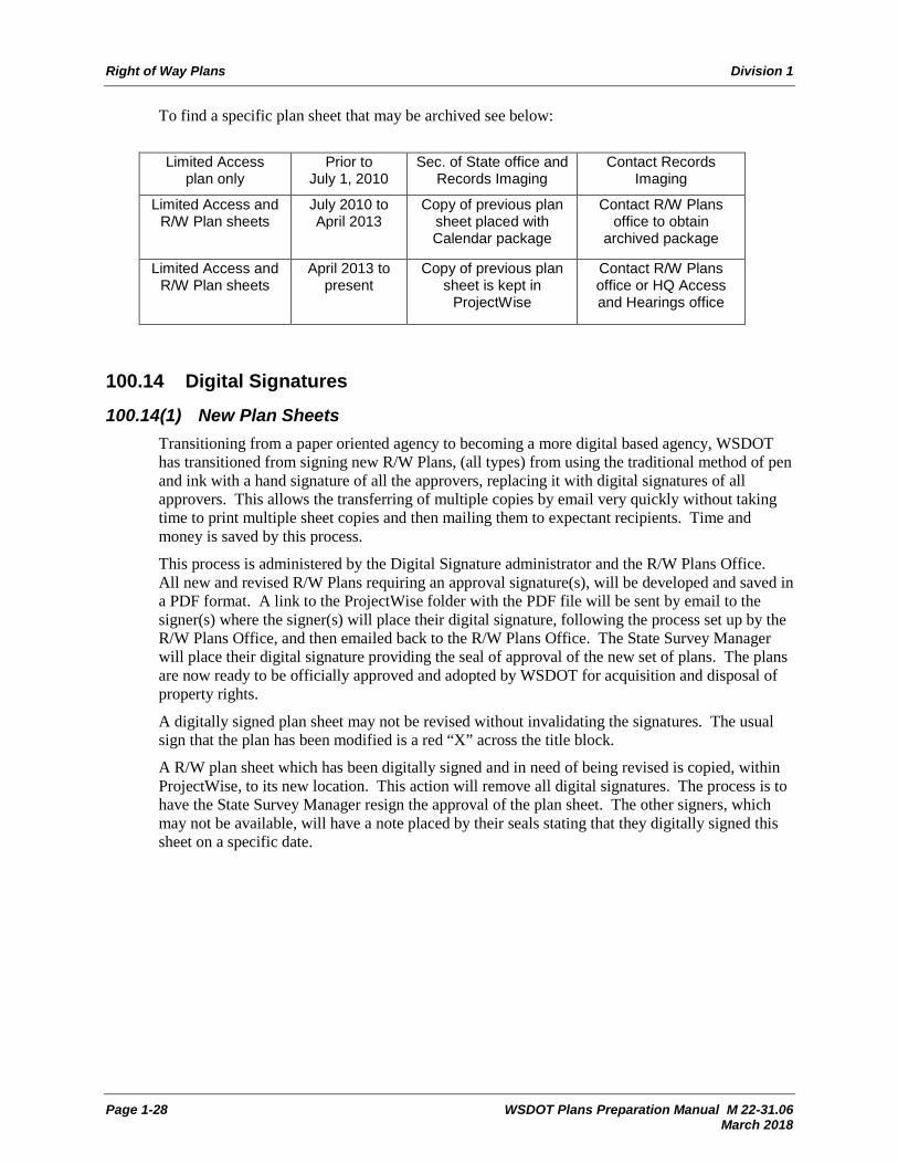
Right of Way Plans Division 1
Page 1-28 WSDOT Plans Preparation Manual M 22-31.06 March 2018
To find a specific plan sheet that may be archived see below:
Limited Access
plan only Prior to
July 1, 2010 Sec. of State office and
Records Imaging Contact Records
Imaging
Limited Access and R/W Plan sheets
July 2010 to April 2013
Copy of previous plan sheet placed with Calendar package
Contact R/W Plans office to obtain
archived package
Limited Access and R/W Plan sheets
April 2013 to present
Copy of previous plan sheet is kept in
ProjectWise
Contact R/W Plans office or HQ Access and Hearings office
100.14 Digital Signatures 100.14(1) New Plan Sheets
Transitioning from a paper oriented agency to becoming a more digital based agency, WSDOT has transitioned from signing new R/W Plans, (all types) from using the traditional method of pen and ink with a hand signature of all the approvers, replacing it with digital signatures of all approvers. This allows the transferring of multiple copies by email very quickly without taking time to print multiple sheet copies and then mailing them to expectant recipients. Time and money is saved by this process.
This process is administered by the Digital Signature administrator and the R/W Plans Office. All new and revised R/W Plans requiring an approval signature(s), will be developed and saved in a PDF format. A link to the ProjectWise folder with the PDF file will be sent by email to the signer(s) where the signer(s) will place their digital signature, following the process set up by the R/W Plans Office, and then emailed back to the R/W Plans Office. The State Survey Manager will place their digital signature providing the seal of approval of the new set of plans. The plans are now ready to be officially approved and adopted by WSDOT for acquisition and disposal of property rights.
A digitally signed plan sheet may not be revised without invalidating the signatures. The usual sign that the plan has been modified is a red “X” across the title block.
A R/W plan sheet which has been digitally signed and in need of being revised is copied, within ProjectWise, to its new location. This action will remove all digital signatures. The process is to have the State Survey Manager resign the approval of the plan sheet. The other signers, which may not be available, will have a note placed by their seals stating that they digitally signed this sheet on a specific date.
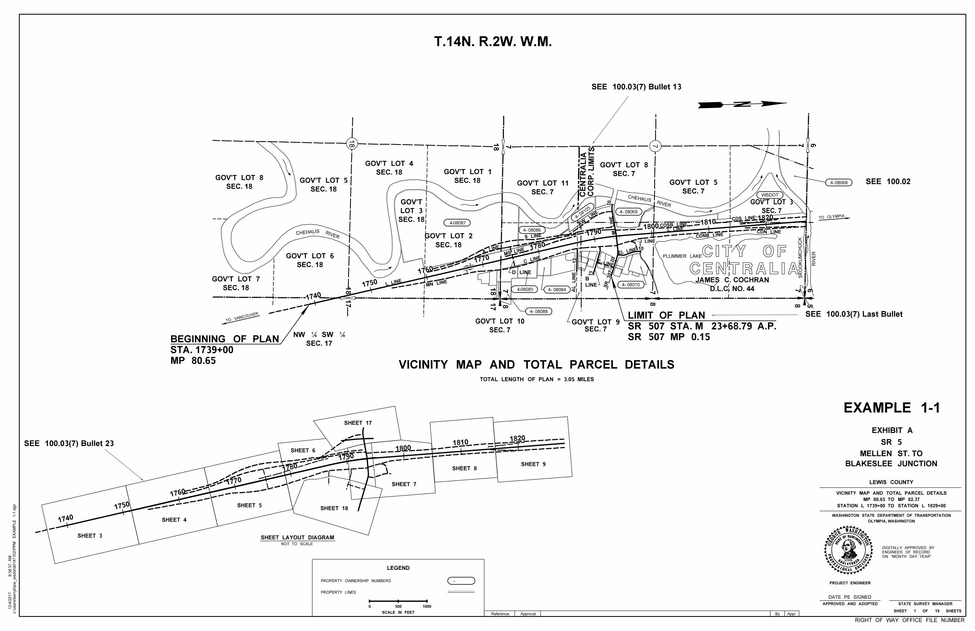
L LINE
MN LINE
A LIN
E
S LINE
MS LINE
AW
LINE
M
LIN
E
L LINECDSB LINE
CDNB LINE
SR 507
CDN LINE
CDS LINE
C LINE
AL
LIN
E
E LINE
EL LINE10
J LINE
D LINE
SEC. 18
GOV'T LOT 6
SEC. 18
GOV'T LOT 2
SEC. 7
GOV'T LOT 10
SEC. 7
GOV'T LOT 5SEC. 18
GOV'T LOT 8
SEC. 18
GOV'T LOT 5
SEC. 18
GOV'T LOT 4
SEC. 18
LOT 3
GOV'T
SEC. 18
GOV'T LOT 1
SEC. 7
GOV'T LOT 11
LINE
B
SEC. 7GOV'T LOT 9
SEC. 7
GOV'T LOT 8
SEC. 7
GOV'T LOT 3
4-08085
4-08086
4-
0810
5 4-08069
4-08070
4-08084
4-08087
WSDOT
VICINITY MAP AND TOTAL PARCEL DETAILS
TOTAL LENGTH OF PLAN = 3.05 MILES
78
18
17
SEC. 17
NW ‚ SW ‚
TO VANCOUVER
SEC. 18
GOV'T LOT 7
2
2
678 5
18 718 7 67
T.14N. R.2W. W.M.
CO
RP. LIMIT
S
CE
NT
RA
LIA
TO OLYMPIA
MP 80.65
STA. 1739+00
BEGINNING OF PLAN
4-08088
CENTRALIA
CITY OF
EXHIBIT A
SR 507 MP 0.15
SR 507 STA. M 23+68.79 A.P.
LIMIT OF PLAN
1687.3
1
16
SE
C
D.L.C. NO. 44
JAMES C. COCHRAN
718
17 8
4-
SEE 100.03(7) Bullet 23
SEE 100.03(7) Bullet 13
SEE 100.02
SEE 100.03(7) Last Bullet
08068
12345
WOFWASHINGTON
GISTERED
ONAL ENGI
NEER
ASHINGTNO
PROJECT ENGINEER
OLYMPIA, WASHINGTON
WASHINGTON STATE DEPARTMENT OF TRANSPORTATION
STATE SURVEY MANAGER
STAT
E
RE
PROFESSI
GEOR
GE
RIGHT OF WAY OFFICE FILE NUMBER
EXAMPLE 1-1
BLAKESLEE JUNCTION
MELLEN ST. TO
SR 5
LEWIS COUNTY
STATION L 1739+00 TO STATION L 1829+00
MP 80.65 TO MP 82.37
VICINITY MAP AND TOTAL PARCEL DETAILS
SHEET 1 OF 19 SHEETS
DATE PE SIGNED
ON "MONTH DAY, YEAR"
ENGINEER OF RECORD
DIGITALLY APPROVED BY
LEGEND
PROPERTY OWNERSHIP NUMBERS
PROPERTY LINES
-
500 1000
SCALE IN FEET
0
SHEET LAYOUT DIAGRAM
NOT TO SCALE
c:\users\b
erryb\p
w_
wsdot\d0147352\P
PM
EX
AM
PLE 1-1.d
gn
8:5
8:5
7
AM
12/4/2
017
APPROVED AND ADOPTED
20
12
10
1740
1750
1760
1770
1780
17901800
18101820
15
1740
1750
1760
1770
1780
1790
18001810
1820
SHEET 9SHEET 8
SHEET 7
SHEET 6
SHEET 5
SHEET 4
SHEET 3
PLUMMER LAKE
CHEHALIS RIVER
CHEHALISRIVER
SK
OO
KU
MC
HU
CK
RIV
ER
SHEET 17
SHEET 18
By Appr.Reference Approval
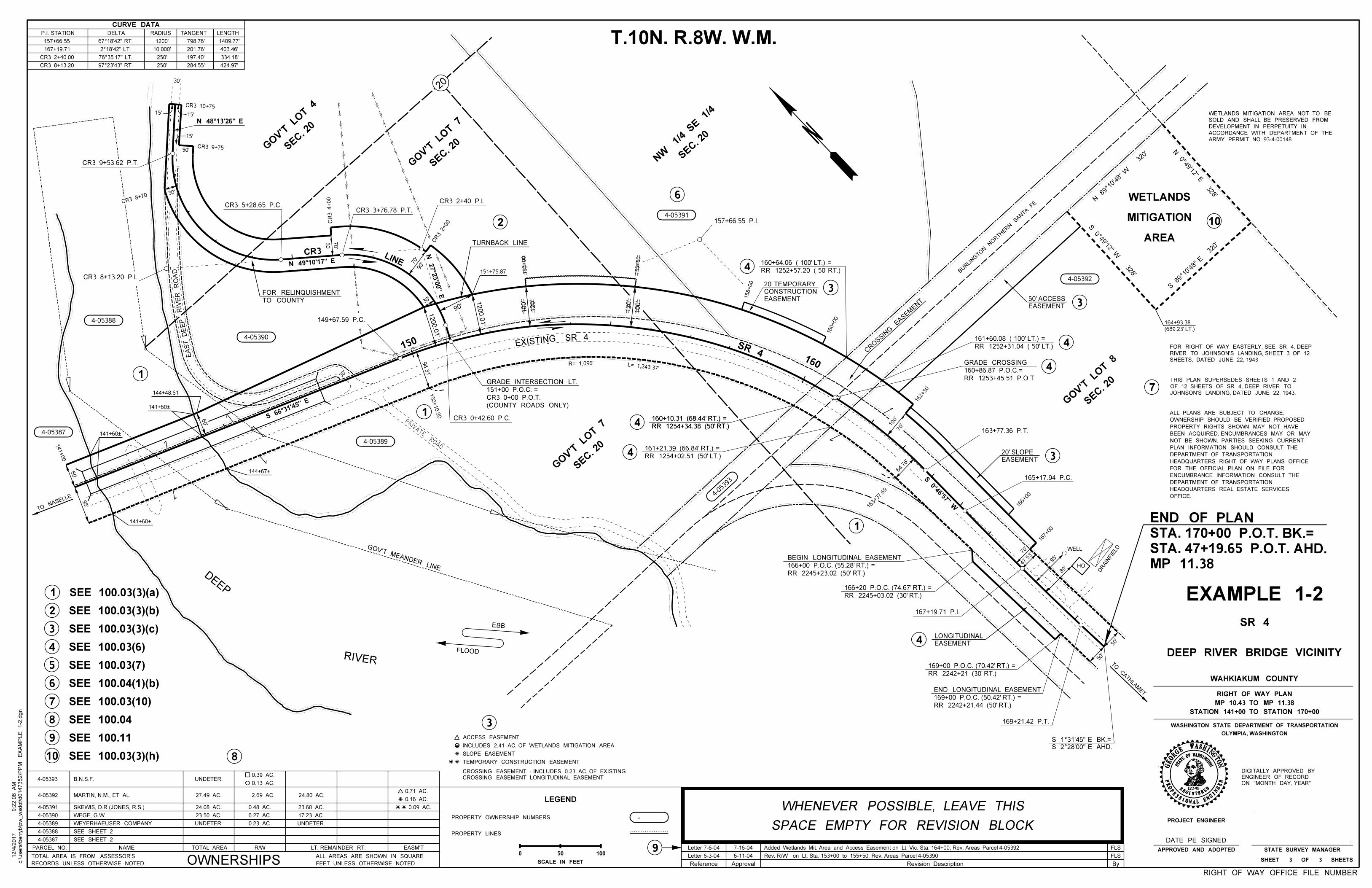
Reference Approval By
PARCEL NO. NAME R/WTOTAL AREA LT. REMAINDER RT. EASM'T
OWNERSHIPSRECORDS UNLESS OTHERWISE NOTED.
TOTAL AREA IS FROM ASSESSOR'S
FEET UNLESS OTHERWISE NOTED.
ALL AREAS ARE SHOWN IN SQUARE
SEE SHEET 2
SEE SHEET 2
4-05387
4-05388
4-05389
4-05390
4-05391
4-05392 MARTIN, N.M., ET AL.
SKEWIS, D.R.(JONES, R.S.)
WEYERHAEUSER COMPANY
WEGE, G.W.
UNDETER. UNDETER.
0.09 AC.
0.16 AC.
4-05393 B.N.S.F. UNDETER.0.39 AC.
0.13 AC.
0.71 AC.27.49 AC. 2.69 AC.
24.08 AC.
23.50 AC.
0.23 AC.
6.27 AC.
0.48 AC.
17.23 AC.
23.60 AC.
24.80 AC.
T.10N. R.8W. W.M.
12345
W
STAT
EOFWASHINGTON
REGISTERED
PROFESSIONAL ENGI
NEER
ASHINGTNOGE
OR
GE
EXAMPLE 1-2
DR
AIN
FIE
LD
TO C
ATHLA
MET
TO NAS
ELLE
SR 4EXISTING
MP 11.38
STA. 47+19.65 P.O.T. AHD.
STA. 170+00 P.O.T. BK.=
END OF PLAN
ARMY PERMIT NO. 93-4-00148
ACCORDANCE WITH DEPARTMENT OF THE
DEVELOPMENT IN PERPETUITY IN
SOLD AND SHALL BE PRESERVED FROM
WETLANDS MITIGATION AREA NOT TO BE
JOHNSON'S LANDING, DATED JUNE 22, 1943.
OF 12 SHEETS OF SR 4, DEEP RIVER TO
THIS PLAN SUPERSEDES SHEETS 1 AND 2
SHEETS, DATED JUNE 22, 1943
RIVER TO JOHNSON'S LANDING, SHEET 3 OF 12
FOR RIGHT OF WAY EASTERLY, SEE SR 4, DEEP
OFFICE.
HEADQUARTERS REAL ESTATE SERVICES
DEPARTMENT OF TRANSPORTATION
ENCUMBRANCE INFORMATION CONSULT THE
FOR THE OFFICIAL PLAN ON FILE. FOR
HEADQUARTERS RIGHT OF WAY PLANS OFFICE
DEPARTMENT OF TRANSPORTATION
PLAN INFORMATION SHOULD CONSULT THE
NOT BE SHOWN. PARTIES SEEKING CURRENT
BEEN ACQUIRED. ENCUMBRANCES MAY OR MAY
PROPERTY RIGHTS SHOWN MAY NOT HAVE
OWNERSHIP SHOULD BE VERIFIED. PROPOSED
ALL PLANS ARE SUBJECT TO CHANGE.
TURNBACK LINE
TO COUNTY
FOR RELINQUISHMENT
DEEP
RIVER
EBB
FLOOD
PRIV
ATE
ROAD
EAS
T
DE
EP
RIV
ER
RO
AD
TEMPORARY CONSTRUCTION EASEMENT
SLOPE EASEMENT
INCLUDES 2.41 AC. OF WETLANDS MITIGATION AREA
ACCESS EASEMENT
CROSSING EASEMENT LONGITUDINAL EASEMENT
CROSSING EASEMENT - INCLUDES 0.23 AC. OF EXISTING
AREA
MITIGATION
WETLANDS
SEC. 2
0
GO
V'T L
OT
4
SEC. 2
0
GO
V'T L
OT
7
SEC. 2
0
NW 1/4
SE 1/4
SEC. 2
0
GO
V'T L
OT
8
SEC. 2
0
GO
V'T L
OT
7
4-05
393
4-05392
4-05391
4-05388
4-05387
4-05390
4-05389
GOV'T MEANDER LINE HO.
BURLI
NGTO
N
NORTHER
N SANTA FE
(689.23' LT.)
164+93.38
CR3 9+53.62 P.T.
WELL
160+00
158+00
166+
00
EASEMENT
CONSTRUCTION
20' TEMPORARY
EASEMENT
20' SLOPE
CR
OSSIN
G EASE
MENT
EASEMENT
50' ACCESS
RR 2245+23.02 (50' RT.)
166+00 P.O.C. (55.28' RT.) =
BEGIN LONGITUDINAL EASEMENT
RR 2245+03.02 (30' RT.)
166+20 P.O.C. (74.67' RT.) =
RR 2242+21 (30' RT.)
169+00 P.O.C. (70.42' RT.) =
RR 2242+21.44 (50' RT.)
169+00 P.O.C. (50.42' RT.) =
END LONGITUDINAL EASEMENT
RR 1254+34.38 (50' RT.)
160+10.31 (68.44' RT.) =
RR 1254+02.51 (50' LT.)
161+21.39 (66.84' RT.) =
L= 1,243.37'R= 1,096'
1
2
3
4
5
6
7
SEE 100.03(3)(b)
SEE 100.03(3)(c)
SEE 100.03(6)
SEE 100.04(1)(b)
1
1
2
6
1
3
7
3
4
4
3
CR3 5+28.65 P.C.
CR3 0+42.60 P.C.
CR3 3+76.78 P.T.
CR3 8+13.20 P.I.
149+67.59 P.C.
CR3 2+40 P.I.
157+66.55 P.I.
RR 1254+34.38 (50' RT.)
160+10.31 (68.44' RT.) =
RR 1252+57.20 ( 50' RT.)
160+64.06 ( 100' LT.) =
RR 1252+31.04 ( 50' LT.)
161+60.08 ( 100' LT.) =
RR 1253+45.51 P.O.T.
160+86.87 P.O.C.=
GRADE CROSSING
163+77.36 P.T.
165+17.94 P.C.
169+21.42 P.T.
167+19.71 P.I.
60'
95'
141+00
153+00
155+50
163+
37.69
162+50
CR3 2+00C
R3 4+00
30'
60'
30'
30'
CR3 10+75
15'
50'CR3 9+75
CR3 8+7
0
150+10.9
0
141+60À
141+60À
144+67À
141+60À
144+48.61
150
15'
15'
CR3 LINE
70'
50'
70'
90'
90'
30'
151+75.87
160
SR 4
100'
70'
167+
00
50'
50'
47.53'
89'
95'
Letter 7-6-04
Letter 6-3-04
7-16-04
6-11-04 Rev. R/W on Lt. Sta. 153+00 to 155+50; Rev. Areas Parcel 4-05390
Added Wetlands Mit. Area and Access Easement on Lt. Vic. Sta. 164+00; Rev. Areas Parcel 4-05392
64.76'
70'
1200.0
1'
1200.0
1'
94.3
1'
120'
100'
100'
120'
FLS
FLS
PROJECT ENGINEER
OLYMPIA, WASHINGTON
WASHINGTON STATE DEPARTMENT OF TRANSPORTATION
STATE SURVEY MANAGER
SR 4
DEEP RIVER BRIDGE VICINITY
WAHKIAKUM COUNTY
STATION 141+00 TO STATION 170+00
MP 10.43 TO MP 11.38
RIGHT OF WAY PLAN
SHEET 3 OF 3 SHEETS
(COUNTY ROADS ONLY)
CR3 0+00 P.O.T.
151+00 P.O.C. =
GRADE INTERSECTION LT.
4
4
4
EASEMENT
LONGITUDINAL4
3
SEE 100.03(7)
8 SEE 100.04
9 SEE 100.11
8
LEGEND
PROPERTY OWNERSHIP NUMBERS
PROPERTY LINES
-
50 100
SCALE IN FEET
0
RIGHT OF WAY OFFICE FILE NUMBER
c:\users\b
erryb\p
w_
wsdot\d0147352\P
PM
EX
AM
PLE 1-2.d
gn
9:2
2:0
8
AM
12/4/2
017
DATE PE SIGNED
ON "MONTH DAY, YEAR"
ENGINEER OF RECORD
DIGITALLY APPROVED BY
APPROVED AND ADOPTED
N 89°10'48"
W 32
0'
S 89°10'48" E 32
0'
S 0°49'12" W
328'
N 0°49'12" E
328'
SPACE EMPTY FOR REVISION BLOCK
WHENEVER POSSIBLE, LEAVE THIS
SEE 100.03(3)(a)
9
SEE 100.03(10)
10
10
SEE 100.03(3)(h)
Revision Description
CURVE DATA
P.I. STATION DELTA RADIUS TANGENT LENGTH
157+66.55 67°18'42" RT. 1200' 798.76' 1409.77'
167+19.71 2°18'42" LT. 10,000' 201.76' 403.46'
CR3 2+40.00 76°35'17" LT. 250' 197.40' 334.18'
CR3 8+13.20 97°23'43" RT. 250' 284.55' 424.97'
20
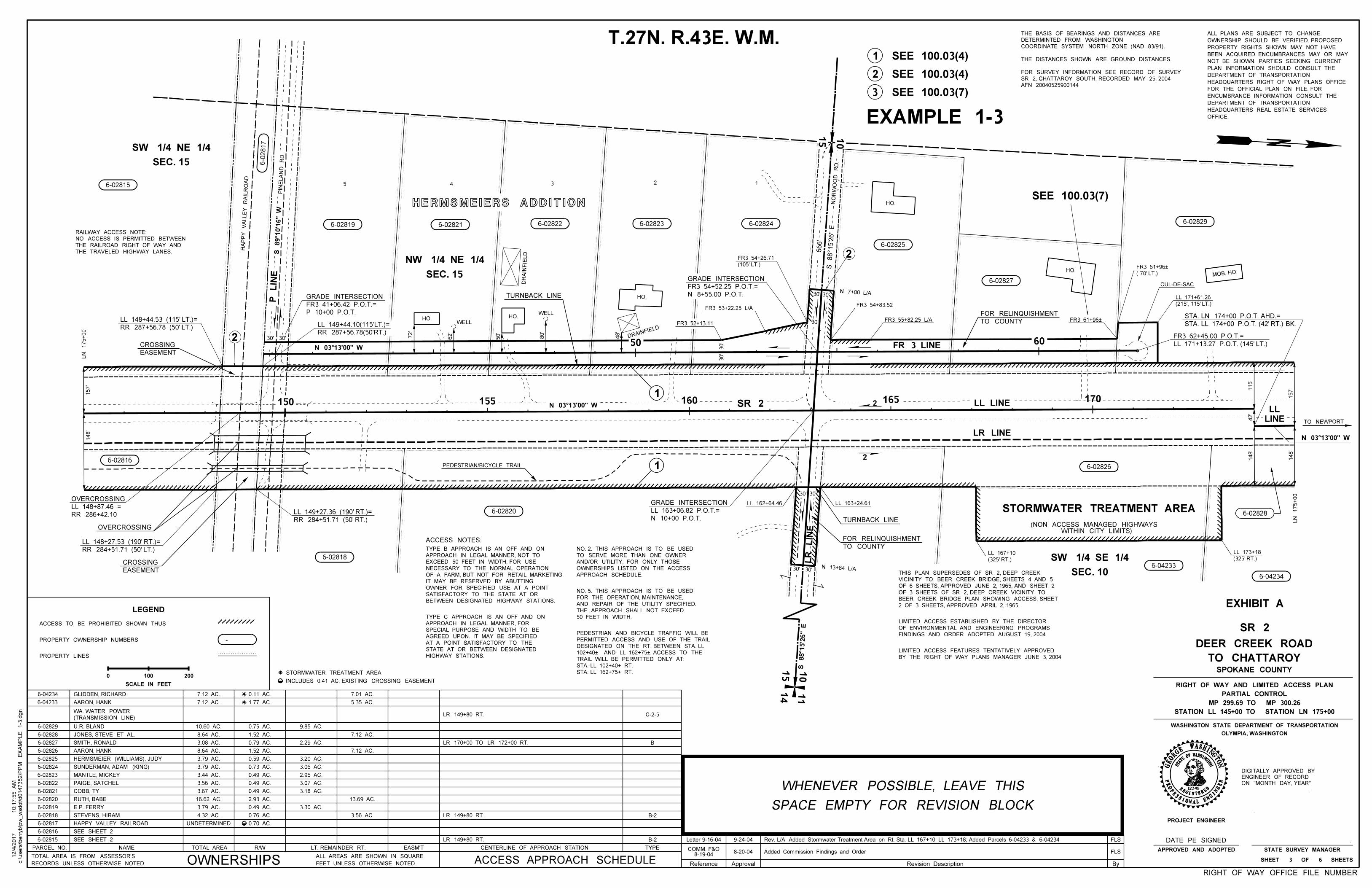
Reference Approval By
PARCEL NO. NAME R/WTOTAL AREA LT. REMAINDER RT. EASM'T
OWNERSHIPSRECORDS UNLESS OTHERWISE NOTED.
TOTAL AREA IS FROM ASSESSOR'S
FEET UNLESS OTHERWISE NOTED.
ALL AREAS ARE SHOWN IN SQUARE
SEE SHEET 2
SEE SHEET 2
12345
W
STAT
EOFWASHINGTON
REGISTERED
PROFESSIONAL ENGI
NEER
ASHINGTNOGE
OR
GE
2
OFFICE.
HEADQUARTERS REAL ESTATE SERVICES
DEPARTMENT OF TRANSPORTATION
ENCUMBRANCE INFORMATION CONSULT THE
FOR THE OFFICIAL PLAN ON FILE. FOR
HEADQUARTERS RIGHT OF WAY PLANS OFFICE
DEPARTMENT OF TRANSPORTATION
PLAN INFORMATION SHOULD CONSULT THE
NOT BE SHOWN. PARTIES SEEKING CURRENT
BEEN ACQUIRED. ENCUMBRANCES MAY OR MAY
PROPERTY RIGHTS SHOWN MAY NOT HAVE
OWNERSHIP SHOULD BE VERIFIED. PROPOSED
ALL PLANS ARE SUBJECT TO CHANGE.
6-02815
6-02816
6-02817
6-02818
6-02819
6-02820
6-02821
6-02822
6-02823
6-02824
6-02825
6-02826
6-02827
6-02828
6-02829
6-04233
6-04234
CENTERLINE OF APPROACH STATION TYPE
ACCESS APPROACH SCHEDULE
B-2
INCLUDES 0.41 AC. EXISTING CROSSING EASEMENT
STORMWATER TREATMENT AREA
FLS9-24-04Letter 9-16-04
FLS8-20-048-19-04
COMM. F&OAdded Commission Findings and Order
Rev. L/A Added Stormwater Treatment Area on Rt. Sta. LL 167+10 LL 173+18; Added Parcels 6-04233 & 6-04234
PROJECT ENGINEER
OLYMPIA, WASHINGTON
WASHINGTON STATE DEPARTMENT OF TRANSPORTATION
STATE SURVEY MANAGER
SR 2
TO CHATTAROY
DEER CREEK ROAD
SPOKANE COUNTY
SHEET 3 OF 6 SHEETS
(TRANSMISSION LINE)
WA. WATER POWER
B-2
HAPPY VALLEY RAILROAD
E.P. FERRY
U.R. BLAND
COBB, TY
7.12 AC.
7.12 AC.
10.60 AC.
8.64 AC.
3.08 AC.
UNDETERMINED
4.32 AC.
3.79 AC.
16.62 AC.
3.67 AC.
3.56 AC.
3.44 AC.
3.79 AC.
3.79 AC.
8.64 AC.
LR 149+80 RT.
LR 149+80 RT.
LR 170+00 TO LR 172+00 RT.
LR 149+80 RT.
3.56 AC.
13.69 AC.
7.01 AC.
5.35 AC.
7.12 AC.
7.12 AC.
9.85 AC.
2.29 AC.
3.30 AC.
3.18 AC.
3.07 AC.
3.20 AC.
3.06 AC.
2.95 AC.
C-2-5
B
0.11 AC.
1.77 AC.
0.75 AC.
1.52 AC.
0.70 AC.
0.76 AC.
0.49 AC.
2.93 AC.
0.49 AC.
0.79 AC.
1.52 AC.
0.59 AC.
0.73 AC.
0.49 AC.
0.49 AC.
T.27N. R.43E. W.M.
EXAMPLE 1-3
STATION LL 145+00 TO STATION LN 175+00
MP 299.69 TO MP 300.26
PARTIAL CONTROL
RIGHT OF WAY AND LIMITED ACCESS PLAN
PEDESTRIAN/BICYCLE TRAIL
DR
AIN
FIE
LD
DRAINFIE
LD
SEC. 10
SW 1/4 SE 1/4
SEC. 15
NW 1/4 NE 1/4
SEC. 15
SW 1/4 NE 1/4
10
15
NO
RW
OO
D
RD.
PIN
EL
AN
D
RD.
HO. HO.
HO.
HO.
HO.MOB. HO.
WELL
WELL
STORMWATER TREATMENT AREA
6-02826
10
15
14 11
2150 155 160 165 170
60
LL LINE
LR LINE
FR 3 LINE
6-02829
6-02827
6-02825
6-02822 6-02823 6-02824
6-04233
6-02828
6-02815
6-02819
6-0
2817
6-02821
6-02818
6-02820
6-02816
HA
PP
Y
VA
LLE
Y
RAIL
RO
AD
50
2
SR 2
HERMSMEIERS ADDITION
12345
LINE
LL
(325' RT.)
LL 173+18
(325' RT.)
LL 167+10
42'
115'
148'
157'
148'
LR
LIN
E
30'30'
30'
APPROACH SCHEDULE.
OWNERSHIPS LISTED ON THE ACCESS
AND/OR UTILITY, FOR ONLY THOSE
TO SERVE MORE THAN ONE OWNER
NO. 2. THIS APPROACH IS TO BE USED
50 FEET IN WIDTH.
THE APPROACH SHALL NOT EXCEED
AND REPAIR OF THE UTILITY SPECIFIED.
FOR THE OPERATION, MAINTENANCE,
NO. 5. THIS APPROACH IS TO BE USED
HIGHWAY STATIONS.
STATE AT OR BETWEEN DESIGNATED
AT A POINT SATISFACTORY TO THE
AGREED UPON. IT MAY BE SPECIFIED
SPECIAL PURPOSE AND WIDTH TO BE
APPROACH IN LEGAL MANNER, FOR
TYPE C APPROACH IS AN OFF AND ON
BETWEEN DESIGNATED HIGHWAY STATIONS.
SATISFACTORY TO THE STATE AT OR
OWNER FOR SPECIFIED USE AT A POINT
IT MAY BE RESERVED BY ABUTTING
OF A FARM, BUT NOT FOR RETAIL MARKETING.
NECESSARY TO THE NORMAL OPERATION
EXCEED 50 FEET IN WIDTH, FOR USE
APPROACH IN LEGAL MANNER, NOT TO
TYPE B APPROACH IS AN OFF AND ON
ACCESS NOTES:
STA. LL 162+75+ RT.
STA. LL 102+40+ RT.
TRAIL WILL BE PERMITTED ONLY AT:
102+40À AND LL 162+75À. ACCESS TO THE
DESIGNATED ON THE RT. BETWEEN STA. LL
PERMITTED ACCESS AND USE OF THE TRAIL
PEDESTRIAN AND BICYCLE TRAFFIC WILL BE
EXHIBIT A
BY THE RIGHT OF WAY PLANS MANAGER JUNE 3, 2004
LIMITED ACCESS FEATURES TENTATIVELY APPROVED
2 OF 3 SHEETS, APPROVED APRIL 2, 1965.
BEER CREEK BRIDGE PLAN SHOWING ACCESS, SHEET
OF 3 SHEETS OF SR 2, DEEP CREEK VICINITY TO
OF 6 SHEETS, APPROVED JUNE 2, 1965, AND SHEET 2
VICINITY TO BEER CREEK BRIDGE, SHEETS 4 AND 5
THIS PLAN SUPERSEDES OF SR 2, DEEP CREEK
THE TRAVELED HIGHWAY LANES.
THE RAILROAD RIGHT OF WAY AND
NO ACCESS IS PERMITTED BETWEEN
RAILWAY ACCESS NOTE:
LL 163+24.61LL 162+64.46
STA. LL 174+00 P.O.T. (42' RT.) BK.
STA. LN 174+00 P.O.T. AHD.=
LL 171+13.27 P.O.T. (145' LT.)
FR3 62+45.00 P.O.T.=
TO NEWPORT
6-04234
LN 175+00
(215', 115' LT.)
LL 171+61.26
( 70' LT.)
FR3 61+96À
FR3 61+96ÀTO COUNTY
FOR RELINQUISHMENT
TURNBACK LINE
P 10+00 P.O.T.
FR3 41+06.42 P.O.T.=
GRADE INTERSECTION N 8+55.00 P.O.T.
FR3 54+52.25 P.O.T.=
GRADE INTERSECTION
FR3 53+22.25 L/A
(105' LT.)
FR3 54+26.71
FR3 52+13.11
N 10+00 P.O.T.
LL 163+06.82 P.O.T.=
GRADE INTERSECTION
RR 286+42.10
LL 148+87.46 =
OVERCROSSING
OVERCROSSING
RR 284+51.71 (50' LT.)
LL 148+27.53 (190' RT.)=
EASEMENT
CROSSING
RR 284+51.71 (50' RT.)
LL 149+27.36 (190' RT.)=
157'
148'
LN 175+00
EASEMENT
CROSSING
RR 287+56.78 (50' LT.)
LL 148+44.53 (115' LT.)=
30' 30'RR 287+56.78(50'RT.)
LL 149+44.10(115'LT.)=
P
LIN
E
80'
62'
72'
50'
48'
30'
30'
30'
TURNBACK LINE
TO COUNTY
FOR RELINQUISHMENT
FR3 55+82.25 L/A
FR3 54+83.52
1
2
SEE 100.03(4)
SEE 100.03(7)
1
1
30'30'
30'
GLIDDEN, RICHARD
AARON, HANK
JONES, STEVE ET AL.
SMITH, RONALD
STEVENS, HIRAM
RUTH, BABE
PAIGE, SATCHEL
MANTLE, MICKEY
SUNDERMAN, ADAM (KING)
HERMSMEIER (WILLIAMS), JUDY
AARON, HANK
3
SEE 100.03(4)
SEE 100.03(7)
CUL-DE-SAC
RIGHT OF WAY OFFICE FILE NUMBER
c:\users\b
erryb\p
w_
wsdot\d0147352\P
PM
EX
AM
PLE 1-3.d
gn
10:1
7:5
5
AM
12/4/2
017
LEGEND
ACCESS TO BE PROHIBITED SHOWN THUS
PROPERTY OWNERSHIP NUMBERS
PROPERTY LINES
-
100 200
SCALE IN FEET
0
DATE PE SIGNED
ON "MONTH DAY, YEAR"
ENGINEER OF RECORD
DIGITALLY APPROVED BY
FINDINGS AND ORDER ADOPTED AUGUST 19, 2004
OF ENVIRONMENTAL AND ENGINEERING PROGRAMS
LIMITED ACCESS ESTABLISHED BY THE DIRECTOR
APPROVED AND ADOPTED
N 03°13'00" W
S 88°1
5'2
6" E
S 88°15'2
6"
E
N 03°13'00" W
N 03°13'00" W
666'
SPACE EMPTY FOR REVISION BLOCK
WHENEVER POSSIBLE, LEAVE THIS
WITHIN CITY LIMITS)(NON ACCESS MANAGED HIGHWAYS
2
N 7+00 L/A
N 13+84 L/A
Revision Description
AFN 20040525900144
SR 2, CHATTAROY SOUTH, RECORDED MAY 25, 2004
FOR SURVEY INFORMATION SEE RECORD OF SURVEY
THE DISTANCES SHOWN ARE GROUND DISTANCES.
COORDINATE SYSTEM NORTH ZONE (NAD 83/91).
DETERMINTED FROM WASHINGTON
THE BASIS OF BEARINGS AND DISTANCES ARE
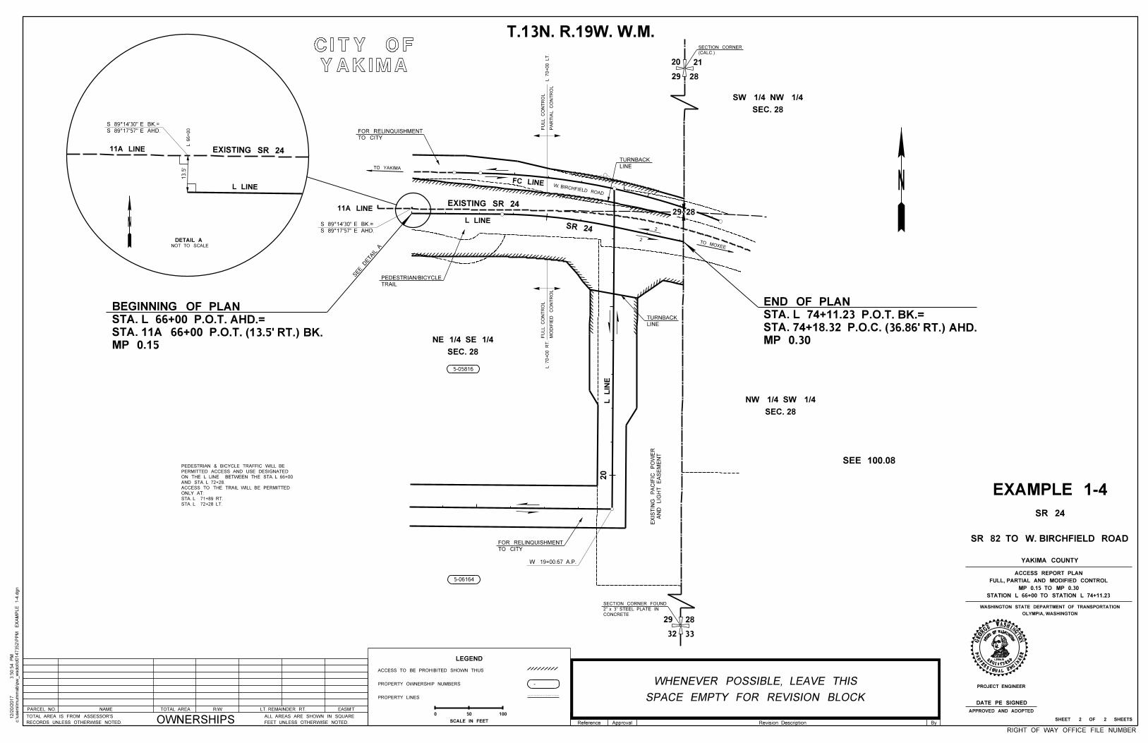
Reference Approval By
PARCEL NO. NAME R/WTOTAL AREA LT. REMAINDER RT. EASM'T
OWNERSHIPSRECORDS UNLESS OTHERWISE NOTED.
TOTAL AREA IS FROM ASSESSOR'S
FEET UNLESS OTHERWISE NOTED.
ALL AREAS ARE SHOWN IN SQUARE
12345
W
STAT
EOFWASHINGTON
REGISTERED
PROFESSIONAL ENGI
NEER
ASHINGTNOGE
OR
GE
SEE 100.08
EXAMPLE 1-4
PROJECT ENGINEER
OLYMPIA, WASHINGTON
WASHINGTON STATE DEPARTMENT OF TRANSPORTATION
SR 24
SR 82 TO W. BIRCHFIELD ROAD
YAKIMA COUNTY
T.13N. R.19W. W.M.
SHEET 2 OF 2 SHEETS
YAKIMA
CITY OF
5-05816
5-06164
MP 0.30
STA. 74+18.32 P.O.C. (36.86' RT.) AHD.
STA. L 74+11.23 P.O.T. BK.=
END OF PLAN
SEC. 28
SW 1/4 NW 1/4
SEC. 28
NW 1/4 SW 1/4
SEC. 28
NE 1/4 SE 1/4MP 0.15
STA. 11A 66+00 P.O.T. (13.5' RT.) BK.
STA. L 66+00 P.O.T. AHD.=
BEGINNING OF PLAN
20
29 28
(CALC.)
SECTION CORNER
21
W. BIRCHFIELD ROAD
AN
D
LIG
HT
EA
SE
ME
NT
EXIS
TIN
G
PA
CIFIC
PO
WE
R
2928
TO MOXEE
LINE
TURNBACK
TO YAKIMA
32 33
2829CONCRETE
2" x 3" STEEL PLATE IN
SECTION CORNER FOUND
W 19+00.67 A.P.
TO CITY
FOR RELINQUISHMENT
TO CITY
FOR RELINQUISHMENT
L LINE
FC LINE
SR 24
EXISTING SR 2411A LINE
2
2
13.5'
L 66+00
EXISTING SR 24
L LINE
11A LINE
LINE
TURNBACK
TRAIL
PEDESTRIAN/BICYCLE
L
LIN
E20
STA. L 72+28 LT.
STA. L 71+89 RT.
ONLY AT:
ACCESS TO THE TRAIL WILL BE PERMITTED
AND STA. L 72+28.
ON THE L LINE BETWEEN THE STA. L 66+00
PERMITTED ACCESS AND USE DESIGNATED
PEDESTRIAN & BICYCLE TRAFFIC WILL BE
RIGHT OF WAY OFFICE FILE NUMBER
c:\users\m
um
mab\p
w_
wsdot\d0147352\P
PM
EX
AM
PLE 1-4.d
gn
3:5
0:5
4 P
M12/2
0/2
017
LEGEND
ACCESS TO BE PROHIBITED SHOWN THUS
PROPERTY OWNERSHIP NUMBERS
PROPERTY LINES
-
50 100
SCALE IN FEET
0APPROVED AND ADOPTED
L 70+00
RT.
PA
RTIA
L
CO
NT
RO
L
FU
LL
CO
NT
RO
LL 70+00 LT.
SPACE EMPTY FOR REVISION BLOCK
WHENEVER POSSIBLE, LEAVE THIS
MO
DIFIE
D
CO
NT
RO
L
FU
LL
CO
NT
RO
L
STATION L 66+00 TO STATION L 74+11.23
MP 0.15 TO MP 0.30
FULL, PARTIAL AND MODIFIED CONTROL
ACCESS REPORT PLAN
SEE DETAIL ANOT TO SCALE
DETAIL A
DATE PE SIGNED
Revision Description
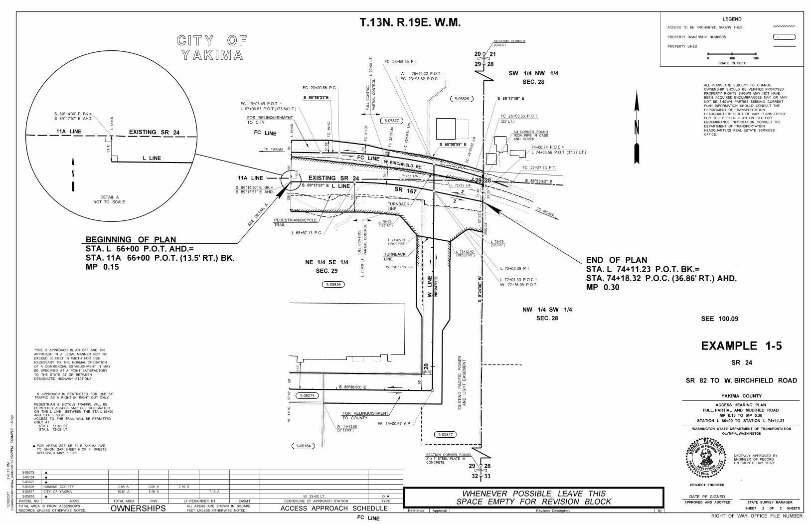
12345
W
STAT
EOFWASHINGTON
REGISTERED
PROFESSIONAL ENGI
NEER
ASHINGTNOGE
OR
GE
PROJECT ENGINEER
OLYMPIA, WASHINGTON
WASHINGTON STATE DEPARTMENT OF TRANSPORTATION
STATE SURVEY MANAGER
Reference Approval By
PARCEL NO. NAME R/WTOTAL AREA LT. REMAINDER RT. EASM'T
OWNERSHIPSRECORDS UNLESS OTHERWISE NOTED.
TOTAL AREA IS FROM ASSESSOR'S
FEET UNLESS OTHERWISE NOTED.
ALL AREAS ARE SHOWN IN SQUARE
CENTERLINE OF APPROACH STATION TYPE
ACCESS APPROACH SCHEDULE
OFFICE.
HEADQUARTERS REAL ESTATE SERVICES
DEPARTMENT OF TRANSPORTATION
ENCUMBRANCE INFORMATION CONSULT THE
FOR THE OFFICIAL PLAN ON FILE. FOR
HEADQUARTERS RIGHT OF WAY PLANS OFFICE
DEPARTMENT OF TRANSPORTATION
PLAN INFORMATION SHOULD CONSULT THE
NOT BE SHOWN. PARTIES SEEKING CURRENT
BEEN ACQUIRED. ENCUMBRANCES MAY OR MAY
PROPERTY RIGHTS SHOWN MAY NOT HAVE
OWNERSHIP SHOULD BE VERIFIED. PROPOSED
ALL PLANS ARE SUBJECT TO CHANGE.
EXAMPLE 1-5
SR 24
SR 82 TO W. BIRCHFIELD ROAD
YAKIMA COUNTY
SHEET 2 OF 2 SHEETS
5-05816
5-05817
5-05826
5-05827
5-06164
5-06275
HUMANE SOCIETY
CITY OF YAKIMA
2.65 A
10.61 A
0.06 A
3.46 A
2.59 A
7.15 A
W 25+00 LT. D-
MP 0.30
STA. 74+18.32 P.O.C. (36.86' RT.) AHD.
STA. L 74+11.23 P.O.T. BK.=
END OF PLANMP 0.15
STA. 11A 66+00 P.O.T. (13.5' RT.) BK.
STA. L 66+00 P.O.T. AHD.=
BEGINNING OF PLAN
5-05816
5-06275
5-06164
5-05817
5-05826
5-05827
YAKIMA
CITY OF
32 33
2829CONCRETE
2" x 3" STEEL PLATE IN
SECTION CORNER FOUND
SR 167L LINE
W
LIN
E
EXISTING SR 24
DESIGNATED HIGHWAY STATIONS.
TO THE STATE AT OR BETWEEN
BE SPECIFIED AT A POINT SATISFACTORY
OF A COMMERCIAL ESTABLISHMENT. IT MAY
NECESSARY TO THE NORMAL OPERATION
EXCEED 50 FEET IN WIDTH FOR USE
APPROACH IN A LEGAL MANNER NOT TO
TYPE D APPROACH IS AN OFF AND ON
SEC. 29
NE 1/4 SE 1/4
SEC. 28
SW 1/4 NW 1/4
SEC. 28
NW 1/4 SW 1/4
11A LINE
S 89°17'57" E AHD.
S 89°14'30" E BK.=
13.5'
20
29 28
21
(CALC.)
SECTION CORNER
29 28
RIGHT OF WAY OFFICE FILE NUMBER
c:\users\m
um
mab\p
w_
wsdot\d0147352\P
PM
EX
AM
PLE 1-5.d
gn
3:4
2:1
3 P
M12/2
0/2
017
DATE PE SIGNED
ON "MONTH DAY, YEAR"
ENGINEER OF RECORD
DIGITALLY APPROVED BY
T.13N. R.19E. W.M.
APPROVED AND ADOPTED
S 89°17'57" E
FC LINE
FC LINE
13.5'
L 66+00
EXISTING SR 24
L LINE
11A LINE
TO CITY
FOR RELINQUISHMENT
TO YAKIMA
L 66+00
L 67+06.63 P.O.T.(173.54' LT.)
FC 19+03.49 P.O.T. =
FC 20+00.86 P.C.
S 88°58'23"E
FC 19+52
FC 21+06
70'
90'
126.5'
51.1
8'
39' F
C 22+04.8
0
25'
FC 22+68.6
2 L/A
W. BIRCHFIELD RD.
LINE
TURNBACK
PA
RTIA
L
CO
NT
RO
L
FU
LL
CO
NT
RO
LL 70+00 LT.
TO MOXEE
PA
RTIA
L
CO
NT
RO
L
FU
LL
CO
NT
RO
LL 70+00 LT.
FC LINE
70'
(125' RT.)
L 70+75
(195.97' RT.)
L 71+65.91
W 24+17.55 L/A
TRAIL
PEDESTRIAN/BICYCLE
125'
L 68+67.13 P.C.
LINE
TURNBACK (192.63' RT.)
L 73+12.40
L 72+03.39 P.T.
L 71+55 L/A
L 72+25 L/A
2
2
(125' RT.)
L 73+75
S 86°53'43" E
FC 27+27.73 P.T.
AND COVER
IRON PIPE IN CASE
1/4 CORNER FOUND
FC 23+68.35 P.I.
L 74+03.56 P.O.T. (37.27' LT.)
74+08.74 P.O.C.=
FC 23+98.62 P.O.C.
W 28+49.22 P.O.T. =
FC 25+28.6
2 L/A
S 68°08'59" E
S 89°17'39" E
APPROVED MAY 5, 1959
TO UNION GAP, SHEET 6 OF 11 SHEETS
FOR AREAS SEE SR 82, E. YAKIMA AVE.
TRAFFIC AS A RIGHT IN RIGHT OUT ONLY.
APPROACH IS RESTRICTED FOR USE BY
STA. L 72+28 LT.
STA. L 71+89 RT.
ONLY AT:
ACCESS TO THE TRAIL WILL BE PERMITTED
AND STA. L 72+28.
ON THE L LINE BETWEEN THE STA. L 66+00
PERMITTED ACCESS AND USE DESIGNATED
PEDESTRIAN & BICYCLE TRAFFIC WILL BE
(25' LT.)
FC 26+03.55 P.O.T.
S 89°26'03" E
TO COUNTY
FOR RELINQUISHMENT
W 19+00.67 A.P.
(57.13' RT.)
W 14+43.69
N0°2
4'5
5"E
S 0°2
4'5
0"
W
W 27+36.05 P.O.T.
L 72+01.33 P.O.C.=
112'
68'
57.4
8'
W
13+00
68'
45.66'
20
AN
D
LIG
HT
EA
SE
ME
NT
EXIS
TIN
G
PA
CIFIC
PO
WE
R
71.4
6'
87.2
5'
2592.0
4'127.6
2'
SPACE EMPTY FOR REVISION BLOCK
WHENEVER POSSIBLE, LEAVE THIS
LEGEND
ACCESS TO BE PROHIBITED SHOWN THUS
PROPERTY OWNERSHIP NUMBERS
PROPERTY LINES
-
100 200
SCALE IN FEET
0
DETAIL A
NOT TO SCALE
SEE DETAIL A
STATION L 66+00 TO STATION L 74+11.23
MP 0.15 TO MP 0.30
FULL, PARTIAL AND MODIFIED ROAD
ACCESS HEARING PLAN
SEE 100.09
Revision Description
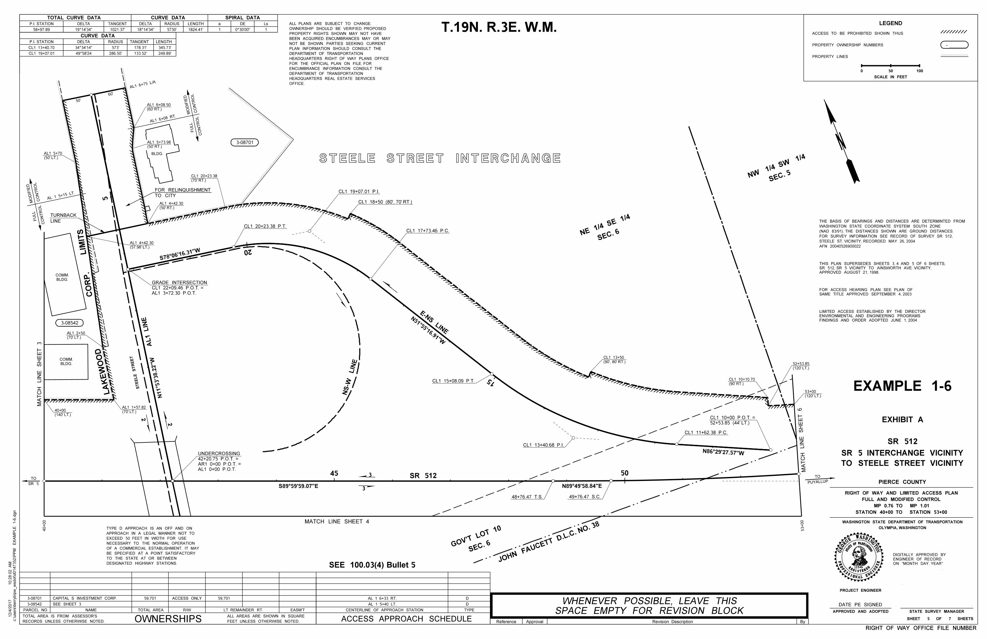
5
5045
20
15
CL1 17+73.46 P.C.
CL1 18+50 (80', 70' RT.)
SEE 100.03(4) Bullet 5
c:\users\b
erryb\p
w_
wsdot\d0147352\P
PM
EX
AM
PLE 1-6.d
gn
10:2
8:0
2
AM
12/4/2
017
PARCEL NO. NAME R/WTOTAL AREA LT. REMAINDER RT. EASM'T
OWNERSHIPSRECORDS UNLESS OTHERWISE NOTED.
TOTAL AREA IS FROM ASSESSOR'S
FEET UNLESS OTHERWISE NOTED.
ALL AREAS ARE SHOWN IN SQUARE
CENTERLINE OF APPROACH STATION TYPE
ACCESS APPROACH SCHEDULE Reference Approval By
OFFICE.
HEADQUARTERS REAL ESTATE SERVICES
DEPARTMENT OF TRANSPORTATION
ENCUMBRANCE INFORMATION CONSULT THE
FOR THE OFFICIAL PLAN ON FILE. FOR
HEADQUARTERS RIGHT OF WAY PLANS OFFICE
DEPARTMENT OF TRANSPORTATION
PLAN INFORMATION SHOULD CONSULT THE
NOT BE SHOWN. PARTIES SEEKING CURRENT
BEEN ACQUIRED. ENCUMBRANCES MAY OR MAY
PROPERTY RIGHTS SHOWN MAY NOT HAVE
OWNERSHIP SHOULD BE VERIFIED. PROPOSED
ALL PLANS ARE SUBJECT TO CHANGE.
D
D3-08701
3-08542 SEE SHEET 3
CAPITAL S INVESTMENT CORP. 59,701 ACCESS ONLY 59,701 AL 1 6+33 RT.
AL 1 5+40 LT.
T.19N. R.3E. W.M.
3-08701
3-08542
STEELE STREET INTERCHANGE
TOTAL CURVE DATA CURVE DATA SPIRAL DATA
P.I. STATION DELTA TANGENT DELTA RADIUS LENGTH a DE Ls
CURVE DATA
P.I. STATION DELTA RADIUS TANGENT LENGTH
573'CL1 13+40.70
CL1 19+07.01
34°34'14"
49°58'24 286.50'
178.31'
133.52'
345.73'
249.89'
111824.41'5730'18°14'34"1021.37'58+97.89 19°14'34" 0°30'00"
SEC. 5NW
1/4 SW
1/4
SEC. 6NE
1/4 SE
1/4
FINDINGS AND ORDER ADOPTED JUNE 1, 2004
ENVIRONMENTAL AND ENGINEERING PROGRAMS
LIMITED ACCESS ESTABLISHED BY THE DIRECTOR
APPROVED AUGUST 21, 1998.
SR 512, SR 5 VICINITY TO AINSWORTH AVE. VICINITY,
THIS PLAN SUPERSEDES SHEETS 3, 4 AND 5 OF 6 SHEETS,
SAME TITLE APPROVED SEPTEMBER 4, 2003
FOR ACCESS HEARING PLAN SEE PLAN OF
BLDG.
BLDG.
COMM.
BLDG.
COMM.
CO
NT
RO
LM
ODIFIE
D
CO
NT
RO
L
FU
LL
AL 1 5+15
LT.
LINE
TURNBACK
(50' LT.)
AL1 5+70
(70' LT.)
AL1 2+50
(60' RT.)
AL1 6+08.50
CO
NT
RO
LM
ODIFIE
D
CO
NT
RO
L
FU
LL
AL1 6+08
RT.
AL1 6+75
L/A
AL1 3+72.30 P.O.T.
CL1 22+09.46 P.O.T. =
GRADE INTERSECTION
+
++
+
++
++
+
+
+
+
+
+
+
DESIGNATED HIGHWAY STATIONS.
TO THE STATE AT OR BETWEEN
BE SPECIFIED AT A POINT SATISFACTORY
OF A COMMERCIAL ESTABLISHMENT. IT MAY
NECESSARY TO THE NORMAL OPERATION
EXCEED 50 FEET IN WIDTH FOR USE
APPROACH IN A LEGAL MANNER NOT TO
TYPE D APPROACH IS AN OFF AND ON
AFN 20040526900022
STEELE ST. VICINITY, RECORDED MAY 26, 2004
FOR SURVEY INFORMATION SEE RECORD OF SURVEY SR 512,
(NAD 83/91). THE DISTANCES SHOWN ARE GROUND DISTANCES.
WASHINGTON STATE COORDINATE SYSTEM SOUTH ZONE
THE BASIS OF BEARINGS AND DISTANCES ARE DETERMINTED FROM
12345
SHINGTON
ERED
L ENGI
NEER
ASHINGTNO
PROJECT ENGINEER
OLYMPIA, WASHINGTON
WASHINGTON STATE DEPARTMENT OF TRANSPORTATION
STATE SURVEY MANAGER
EXHIBIT A
APPROVED AND ADOPTED
RIGHT OF WAY OFFICE FILE NUMBERRIGHT OF WAY OFFICE FILE NUMBER
DATE PE SIGNED
ON "MONTH DAY, YEAR"
ENGINEER OF RECORD
DIGITALLY APPROVED BY
EXAMPLE 1-6
SR 512
TO STEELE STREET VICINITY
SR 5 INTERCHANGE VICINITY
PIERCE COUNTY
STATION 40+00 TO STATION 53+00
MP 0.76 TO MP 1.01
FULL AND MODIFIED CONTROL
RIGHT OF WAY AND LIMITED ACCESS PLAN
SHEET 5 OF 7 SHEETS
W
STAT
EOFWA
REGIST
PROFESSIONA
GEOR
GE
TO CITY
FOR RELINQUISHMENT
60'
50'
(50' RT.)
AL1 5+73.98
(70' RT.)
CL1 20+23.38
(50' RT.)
AL1 4+42.30
CL1 19+07.01 P.I.
CL1 20+23.38 P.T.
CL1 15+08.09 P.T.
E-N
S LIN
E
(57.98' LT.)
AL1 4+42.30
LA
KE
WO
OD
CO
RP. LIMIT
S
MA
TC
H
LIN
E
SH
EE
T 3 AL1 LIN
E
STE
ELE S
TR
EE
T
2
2
(70' LT.)
AL1 1+57.82
SR 512
MATCH LINE SHEET 4
SPACE EMPTY FOR REVISION BLOCK
WHENEVER POSSIBLE, LEAVE THIS
MA
TC
H
LIN
E
SH
EE
T 6
48+76.47 T.S.
49+76.47 S.C.
SR 5
TOPUYALLUP
TO
(90', 80' RT.)
CL1 13+50
SEC. 6GOV'T
LOT 10
JOHN
FAUCETT D.L.C. N
O. 38
(140' LT.)
40+00
40+00
CL1 11+62.38 P.C.
CL1 13+40.68 P.I.
53+00
(120' LT.)
53+00
(120' LT.)
52+53.85
52+53.85 (44' LT.)
CL1 10+00 P.O.T. =
(90' RT.)
CL1 10+10.70
NS-W
LIN
E
AL1 0+00 P.O.T.
AR1 0+00 P.O.T. =
42+20.75 P.O.T. =
UNDERCROSSING
Revision Description
3
3
LEGEND
ACCESS TO BE PROHIBITED SHOWN THUS
PROPERTY OWNERSHIP NUMBERS
PROPERTY LINES
-
50 100
SCALE IN FEET
0
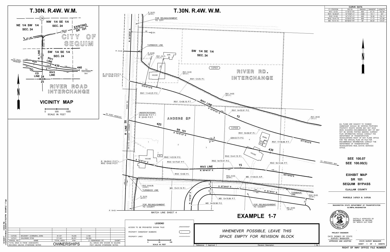
c:\users\m
um
mab\p
w_
wsdot\d0147352\P
PM
EX
AM
PLE 1-7.d
gn
4:4
8:0
0 P
M12/1
8/2
017
c:\users\m
um
mab\p
w_
wsdot\d0147352\P
PM
EX
AM
PLE 1-7.d
gn
4:4
8:0
0 P
M12/1
8/2
017
PARCEL NO. NAME R/WTOTAL AREA LT. REMAINDER RT. EASM'T
OWNERSHIPSRECORDS UNLESS OTHERWISE NOTED.
TOTAL AREA IS FROM ASSESSOR'S
FEET UNLESS OTHERWISE NOTED.
ALL AREAS ARE SHOWN IN SQUARE
Reference Approval By
RIGHT OF WAY OFFICE FILE NUMBERRIGHT OF WAY OFFICE FILE NUMBER
3-07636
3-07631
81,337 2,108BOUSHEY (CORNISH), JOHN
ZALEINSKI, STAN 211,041
79,229
46,057 164,984
T.30N. R.4W. W.M.
420
430440 3-07631
3-07636
T.30N. R.4W. W.M.
24
25
CURVE DATA
P.I. STATION DELTA RADIUS TANGENT LENGTH
11°40'10" RT.
10°09'43" RT.RIV2 15+41.70 141.89'
125.87'
162.94'
80.20'
71.13'
151.1'
81.75'
80'
800'
800'
90°08'45" RT.
RIV1 12+25
MD 15+31.19
500 1000
SCALE IN FEET
0
VICINITY MAP
SEQUIM
CITY OF
INTERCHANGE
RIVER ROAD
SEC. 24
NW 1/4 SE 1/4
SEC. 24
NE 1/4 SW 1/4
SEC. 24
SW 1/4 SE 1/4
ANGELES
TO PORT
BAY
DISCOVERY
TO
SR 101
EXISTING
RIV
ER
RD.
OLYMPIA, WASHINGTON
WASHINGTON STATE DEPARTMENT OF TRANSPORTATION
CLALLAM COUNTY
PARCELS 3-07631 & 3-07636
12345
SHINGTON
ERED
L ENGI
NEER
ASHINGTNO
PROJECT ENGINEER
STATE SURVEY MANAGERAPPROVED AND ADOPTED
ON "MONTH DAY, YEAR"
ENGINEER OF RECORD
DIGITALLY APPROVED BY
SHEET 1 OF 1 SHEETS
W
STAT
EOFWA
REGIST
PROFESSIONA
GEOR
GE
SEQUIM BYPASS
SR 101
EXHIBIT MAP
2
2
R
LIN
E
LINE
RIV1
LINE
RIV2
LINE
CD
SEC. 24
SW 1/4 SE 1/4
LEGEND
ACCESS TO BE PROHIBITED SHOWN THUS
PROPERTY OWNERSHIP NUMBERS
PROPERTY LINES
-
50 100
SCALE IN FEET
0
MATCH LINE SHEET 4
TO CITY
FOR RELINQUISHMENT
N 01°5
9'2
5" E
S 81°36'51" E
S 87°54'43" E
INTERCHANGE
RIVER RD.
R 16+05
3
2
1
4
ANDERS SP
20
SH.
GAR.
HOUSE
SH.SH.
BARN
HOUSE
HOUSE
SH.
594.1
2' T
O
QU
AR
TE
R
CO
RN
ER
N 1°5
6'2
9" E
15
430
425
428+03.73 P.C.
15
TURNBACK LINE
86'
R 23+00
RIV1 10+00 P.O.T.
R 21+70.34 P.O.T.=
130'
RIV1 11+43.25 P.C.
RIV1 13+06.19 P.T.
RIV1 12+25 P.I.
RIV1 LINE
RIV1 14+55.91 P.C.
RIV1 16+06.97 P.I.
RIV1 17+56.86 P.T.
R 20+00 P.O.T.
423+63.66 P.O.T. =
UNDERCROSSING
2
2
R
LIN
ERIV
ER
RD.
SR 101
TO DISCOVERY BAYRIV2 10+00 P.O.T.
R 18+29.61 P.O.T.=
TURNBACK LINE
TO COUNTY
FOR RELINQUISHMENT
RIV2 1+23.50 P.C.
RIV2 LINE
MD 15+31.19 P.I.
RIV2 16+12.46 P.T. RIV2 12+75.67 P.T.
RIV2 14+70.57 P.C.
RIV2 15+41.70 P.I.
30'
30'
30'
LINE
TURNBACK
MD 17+04.03 A.P.
TO COUNTY
FOR RELINQUISHMENT
MD 15+76.86 P.T.
MD 14+50.98 P.C.
Revision Description
SURVEY MANAGER
DATE SIGNED BY STATE
121'
SPACE EMPTY FOR REVISION BLOCK
WHENEVER POSSIBLE, LEAVE THIS
EXAMPLE 1-7
SEE 100.00(5)
SEE 100.07
TO PORT ANGELES
(50' RT.)
R 24+50
(50' RT.)
R 22+60
(75' LT.)
RIV1 10+75
(65' LT.)
RIV1 12+00
(50' LT.)
RIV1 14+00
(75' LT.)
RIV1 18+00
RIV2 12+00 14°31'52" LT. 600' 76.50' 152.17'
RIV1 16+06.97 1400' 301'
(65' RT.)
RIV2 18+00
(30' RT.)
MD 19+00
(60' RT.)
RIV2 15+00
RIV2 12+00 P.I.
(40' RT.)
R 16+50
(70' RT.)
RIV2 10+64.86
OFFICE.
HEADQUARTERS REAL ESTATE SERVICES
DEPARTMENT OF TRANSPORTATION
ENCUMBRANCE INFORMATION CONSULT THE
FOR THE OFFICIAL PLAN ON FILE. FOR
HEADQUARTERS RIGHT OF WAY PLANS OFFICE
DEPARTMENT OF TRANSPORTATION
PLAN INFORMATION SHOULD CONSULT THE
NOT BE SHOWN. PARTIES SEEKING CURRENT
BEEN ACQUIRED. ENCUMBRANCES MAY OR MAY
PROPERTY RIGHTS SHOWN MAY NOT HAVE
OWNERSHIP SHOULD BE VERIFIED. PROPOSED
ALL PLANS ARE SUBJECT TO CHANGE.
24
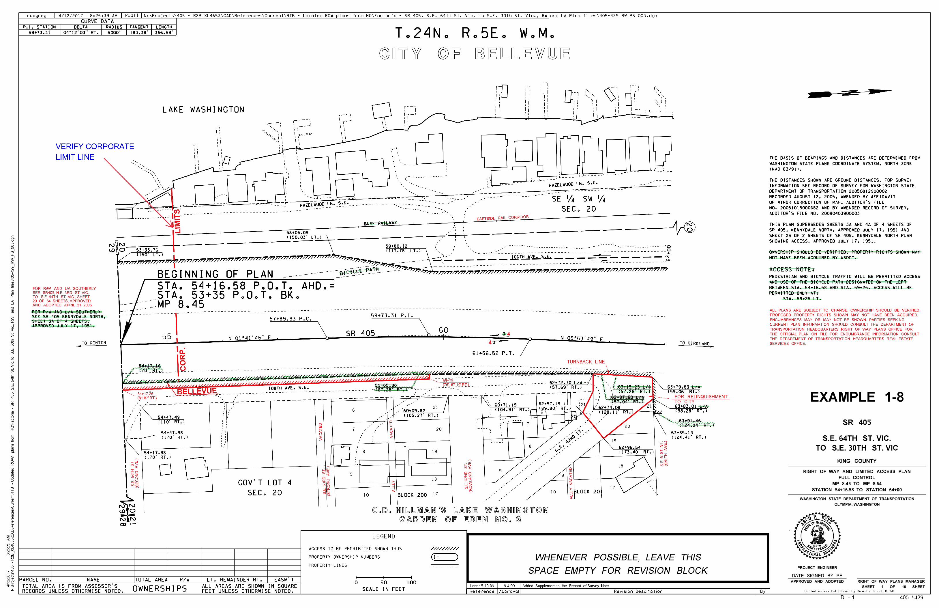
SR 405
TO S.E. 30TH ST. VIC
S.E. 64TH ST. VIC.
KING COUNTY
STATION 54+16.58 TO STATION 64+00
MP 8.45 TO MP 8.64
FULL CONTROL
RIGHT OF WAY AND LIMITED ACCESS PLAN
EXAMPLE 1-8
SEE 100.09
12345
P.DCBA
XWZY
PROJECT ENGINEER
APPROVED AND ADOPTED
OLYMPIA, WASHINGTON
WASHINGTON STATE DEPARTMENT OF TRANSPORTATION
RIGHT OF WAY PLANS MANAGER
SHEET 1 OF 10 SHEET
DATE SIGNED BY PE
STAT
EOFWASHINGTON
REGISTERED
PROFESSIONAL ENGI
NEER
SPACE EMPTY FOR REVISION BLOCK
WHENEVER POSSIBLE, LEAVE THIS
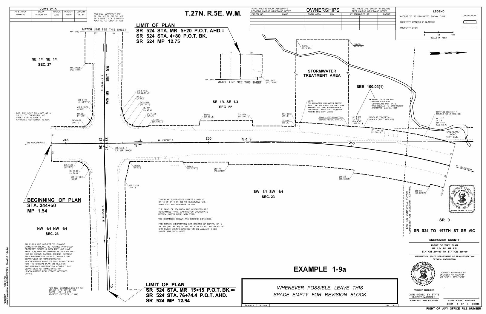
CURVE DATA
P.I. STATION DELTA RADIUS TANGENT LENGTH
THE BASIS OF BEARINGS AND DISTANCES ARE
THE DISTANCES SHOWN ARE GROUND DISTANCES.
FOR SURVEY INFORMATION SEE RECORD OF SURVEY SR 9,
SR 524 (MALTBY RD) VIC. TO 164TH ST SE VIC. RECORDED IN
UNDER AFN 200701035253.
MP 1.54
STA. 244+50
BEGINNING OF PLAN
TREATMENT AREA
STORMWATER
THIS PLAN SUPERSEDES SHEETS 9 AND 10
SR 524 MP 12.94
SR 524 STA. 76+74.4 P.O.T. AHD.
SR 524 STA. MR 15+15 P.O.T. BK.=
LIMIT OF PLAN
SR 524 MP 12.94
SR 524 STA. 76+74.4 P.O.T. AHD.
SR 524 STA. MR 15+15 P.O.T. BK.=
LIMIT OF PLAN
SR 524 MP 12.94
SR 524 STA. 76+74.4 P.O.T. AHD.
SR 524 STA. MR 15+15 P.O.T. BK. =
LIMIT OF PLAN
SNOHOMISH COUNTY, WASHINGTON ON JANUARY 3, 2007
OF 18 OF SR 9, SR 522 TO CLEARVIEW VIC.,
LEGEND
ACCESS TO BE PROHIBITED SHOWN THUS
PROPERTY OWNERSHIP NUMBERS
PROPERTY LINES
-
50 100
SCALE IN FEET
0
c:\users\m
um
mab\p
w_
wsdot\d0147352\P
PM
EX
AM
PLE 1-9
a.d
gn
4:4
9:4
0 P
M12/1
8/2
017
c:\users\m
um
mab\p
w_
wsdot\d0147352\P
PM
EX
AM
PLE 1-9
a.d
gn
4:4
9:4
0 P
M12/1
8/2
017
By Appr.Reference Approval
N
R
PR
OF
ES
S
IO
E
TA
TS
56789
DNALAL
N
S
UR
VE
YO
R
OT
G
NIHSAWFO
EGISTERE
D
APPROVED SEPOINTEMBER 16, 1994.
ADOPTED OCTOBER 27, 1995
SHEET 1 OF 1 SHEET,
JCT. SR 9 TO JCT. SR 522,
FOR R/W EASTERLY, SEE SR 524,
RIGHT OF WAY OFFICE FILE NUMBERRIGHT OF WAY OFFICE FILE NUMBER
767.64'386.86'2,500'255+64.49 T.27N. R.5E. W.M.
SR 524
MR
LIN
E
SR 9245250
255
15
AD
MINIS
TR
ATIO
N
EA
SE
ME
NT (3
00' W
IDE)
EXIS
TIN
G
BO
NN
EVIL
LE
PO
WE
R
SEC. 27
NE 1/4 NE 1/4
SEC. 22
SE 1/4 SE 1/4
SEC. 23
SW 1/4 SW 1/4
SEC. 26
NW 1/4 NW 1/4
EXPIRES JANUARY 14, 2013
DETERMINED FROM WASHINGTON COORDINATE
SYSTEM NORTH ZONE (NAD 83/91).
SR 524 MP 12.75
SR 524 STA. 4+80 P.O.T. BK.
SR 524 STA. MR 5+20 P.O.T. AHD.=
LIMIT OF PLAN
TO SMOHOMISH
TO WOODINVILLE
OFFICE.
HEADQUARTERS REAL ESTATE SERVICES
DEPARTMENT OF TRANSPORTATION
ENCUMBRANCE INFORMATION CONSULT THE
FOR THE OFFICIAL PLAN ON FILE. FOR
HEADQUARTERS RIGHT OF WAY PLANS OFFICE
DEPARTMENT OF TRANSPORTATION
PLAN INFORMATION SHOULD CONSULT THE
NOT BE SHOWN. PARTIES SEEKING CURRENT
BEEN ACQUIRED. ENCUMBRANCES MAY OR MAY
PROPERTY RIGHTS SHOWN MAY NOT HAVE
OWNERSHIP SHOULD BE VERIFIED. PROPOSED
ALL PLANS ARE SUBJECT TO CHANGE.
(NOT BUILT)ROAD
OVERLAND
79'
80'
258+50
12345
WWASHINGTON
STERED
AL ENGI
NEER
ASHINGTNO
PROJECT ENGINEER
OLYMPIA, WASHINGTON
WASHINGTON STATE DEPARTMENT OF TRANSPORTATION
STATE SURVEY MANAGERAPPROVED AND ADOPTED
ON "MONTH DAY, YEAR"
ENGINEER OF RECORD
DIGITALLY APPROVED BY
SR 9
SR 524 TO 197TH ST SE VIC
SNOHOMISH COUNTY
STATION 244+50 TO STATION 258+50
MP 1.54 TO MP 1.81
RIGHT OF WAY PLAN
SHEET 2 OF 6 SHEETS
STAT
EOF
REGI
PROFESSION
GEOR
GE
L= 54.95'
R= 55.50'
(663'À LT.)
254+32À
(651'À LT.)
252+87
(65', 70' RT.)
249+10
(90', 80' RT.)
258+00
(57', 60' LT.)
247+90
(57' LT.)
247+55.68
(80', 90' RT.)
255+20
(70', 80' RT.)
250+70
(70' LT.)
MR 11+35
(65' RT.)
247+24(61.5' RT.)
245+39.87
(55' RT.)
MR 10+94.35
62'
60'
(60' LT.)
245+68.97
(42' RT.)
MR 8+95.30
(41', 42' RT.)
MR 8+70
L= 54.9'
R= 55'
(70', 41' RT.)
MR 7+22À
APPROVED SEPTEMBER 16, 1994.
SHEET 9 OF 18 SHEETS,
SR 522 TO CLEARVIEW VIC.,
FOR R/W SOUTHERLY, SEE SR 9,
N 1°21'20" E
S 89°2
1'4
4" E
MATCH LINE SEE THIS SHEET
ADOPTED OCTOBER 27, 1995
SR 9, SHEET 2 OF 2 SHEETS,
SR 524, JCT. SR 527 TO JCT.
FOR R/W WESTERLY, SEE
MR 6+1070' 60'
L= 47.58'
R= 59'
S
TE
VEN S. BRY
AN
T
(60', 62.47' LT.)
MR 8+81.63
(75.15' LT.)
247+13.08
L= 44.5'
R= 91'
(60', 75' LT.)
249+70(75', 55' LT.)
251+55À
(55' LT.)
253+01.77255+00À (50' LT. 1938 C/L)
254+81À (70', 69.60' LT.) =
APPROVED MAY 24, 1938
WOODINVILLE TO SNOHOMISH,
CENTERLINE PER SR 9,
REFERENCES R/W
SPIRAL DATA SHOWN
1938 C/L
L= 2.4
a= 1 2/3(70' LT.)
253+01.30
(60', 75' RT.)
MR 6+00
MATCH LINE SEE THIS SHEET
SEE 100.03(1)
1938 C/L
L= 2.4
a= 1 2/3255+54.5 (50' LT. 1938 C/L)
255+34.97 (73.45' LT.) =
257+59.5 (50' LT 1938 C/L)
257+41.82 (80.24' LT) =
L= 213.44'
R= 1,482.39'
SPACE EMPTY FOR REVISION BLOCK
WHENEVER POSSIBLE, LEAVE THIS
EXAMPLE 1-9a
SURVEY MANAGER
DATE SIGNED BY STATE
2
2
75'70'
MR 6+10
MR 15+15
PARCEL NO. NAME R/WTOTAL AREA LT. REMAINDER RT. EASM'T
OWNERSHIPSRECORDS UNLESS OTHERWISE NOTED.
TOTAL AREA IS FROM ASSESSOR'S
FEET UNLESS OTHERWISE NOTED.
ALL AREAS ARE SHOWN IN SQUARE
A.P. MR 10+00
246+34.8 =
22
27
26
23
WITHIN THE CITY LIMITS
TREATMENT AREA AND HIGHWAY
SEPERATING THE STORMWATER
SHALL BE NO RIGHT OF WAY LINE
ON MANAGED HIGHWAYS THERE
NOTE:
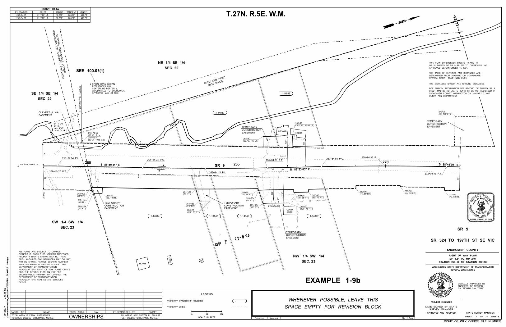
PARCEL NO. NAME R/WTOTAL AREA LT. REMAINDER RT. EASM'T
OWNERSHIPSRECORDS UNLESS OTHERWISE NOTED.
TOTAL AREA IS FROM ASSESSOR'S
FEET UNLESS OTHERWISE NOTED.
ALL AREAS ARE SHOWN IN SQUARE
CURVE DATA
P.I. STATION DELTA RADIUS TANGENT LENGTH
SP 7 (1
-81)
1
2
THE BASIS OF BEARINGS AND DISTANCES ARE
THE DISTANCES SHOWN ARE GROUND DISTANCES.
FOR SURVEY INFORMATION SEE RECORD OF SURVEY SR 9,
SR524 (MALTBY RD) VIC. TO 164TH ST SE VIC. RECORDED IN
UNDER AFN 200701035253.
(NOT BUIL
T)OVERLAND
ROAD
THIS PLAN SUPERSEDES SHEETS 10 AND 11
SNOHOMISH COUNTY, WASHINGTON. ON JANUARY 3, 2007
OF 18 SHEETS OF SR 9, SR 522 TO CLEARVIEW VIC.,
22
23
c:\users\m
um
mab\p
w_
wsdot\d0147352\P
PM
EX
AM
PLE 1-9
b.d
gn
4:5
1:0
3 P
M12/1
8/2
017
c:\users\m
um
mab\p
w_
wsdot\d0147352\P
PM
EX
AM
PLE 1-9
b.d
gn
4:5
1:0
3 P
M12/1
8/2
017
By Appr.Reference Approval
APPROVED SEPOINTEMBER 16, 1994.
RIGHT OF WAY OFFICE FILE NUMBERRIGHT OF WAY OFFICE FILE NUMBER
419.78'209.92'10,500'263+94.15
269+94.57 419.78'209.92'10,500'
T.27N. R.5E. W.M.
258+97.64 P.I.
259+45.27 P.T.
260261+84.24 P.C.
263+94.15 P.I.
265
266+04.01 P.T. 267+84.65 P.C.
270
269+94.56 P.I.
272+04.43 P.T.
1-14844 1-14845 1-14846 1-14847
1-14848
1-14937
SEC. 22
NE 1/4 SE 1/4
SEC. 22
SE 1/4 SE 1/4
SEC. 23
SW 1/4 SW 1/4
SEC. 23
NW 1/4 SW 1/4
GARAGEHOUSE
SH
HOUSE
SH
ED
FOUNTAIN
BLDG.
COMM.
OFFICE.
HEADQUARTERS REAL ESTATE SERVICES
DEPARTMENT OF TRANSPORTATION
ENCUMBRANCE INFORMATION CONSULT THE
FOR THE OFFICIAL PLAN ON FILE. FOR
HEADQUARTERS RIGHT OF WAY PLANS OFFICE
DEPARTMENT OF TRANSPORTATION
PLAN INFORMATION SHOULD CONSULT THE
NOT BE SHOWN. PARTIES SEEKING CURRENT
BEEN ACQUIRED. ENCUMBRANCES MAY OR MAY
PROPERTY RIGHTS SHOWN MAY NOT HAVE
OWNERSHIP SHOULD BE VERIFIED. PROPOSED
ALL PLANS ARE SUBJECT TO CHANGE.
(50' LT 1938 C/L)
259+99.5
(78.30' LT.) =
259+79.55
EASEMENT
CULVERT & WALL
TO WOODINVILLE
EASEMENT
CONSTRUCTION
TEMPORARY
EASEMENT
CONSTRUCTION
TEMPORARY
EASEMENT
CONSTRUCTION
TEMPORARY
96'
105'
80'
79'
132'
108'
EASEMENT
CONSTRUCTION
TEMPORARY
258+50
272+50
SR 9
SPACE EMPTY FOR REVISION BLOCK
WHENEVER POSSIBLE, LEAVE THIS
LEGEND
PROPERTY OWNERSHIP NUMBERS
PROPERTY LINES
-
50 100
SCALE IN FEET
0
12345
W
STAT
EOFWASHINGTON
REGISTERED
PROFESSIONAL ENGI
NEER
ASHINGTNOGE
OR
GE
PROJECT ENGINEER
OLYMPIA, WASHINGTON
WASHINGTON STATE DEPARTMENT OF TRANSPORTATION
STATE SURVEY MANAGER
EXPIRES FEBRUARY 30, 2006
APPROVED AND ADOPTED
ON "MONTH DAY, YEAR"
ENGINEER OF RECORD
DIGITALLY APPROVED BY
SR 9
SR 524 TO 197TH ST SE VIC
SNOHOMISH COUNTY
STATION 258+50 TO STATION 272+50
MP 1.81 TO MP 2.07
RIGHT OF WAY PLAN
SHEET 3 OF 6 SHEETS
N
R
PR
OF
ES
S
IO
E
TA
TS
56789
DNALAL
N
S
UR
VE
YO
R
OT
G
NIHSAWFO
EGISTERE
D
S
TE
VEN S. BRY
AN
T
EXAMPLE 1-9b
AD
MINIS
TR
ATIO
N
EAS
EM
EN
T (3
00' W
IDE)
EXIS
TIN
G
BO
NN
EVIL
LE P
OW
ER
(70', 170' LT.)
272+30
70'
80'
(70', 80' RT.)
272+00(65', 70' RT.)
270+50
(75', 65' RT.)
269+00
(105', 70', 65.66' LT.)
266+90
(120', 75' RT.)
266+70
(75', 85' RT.)
266+90(85', 75' RT.)
267+40
(120' RT.)
265+86À
(75' RT.)
265+73À
(70', 75' RT.)
265+70(70' RT.)
263+63À
(110' RT.)
263+76À
(110', 70' RT.)
264+10(90' RT.)
260+19À
(70' RT.)
260+12À
(80' RT.)
260+16À
(90', 70' RT.)
260+50
EASEMENT
CONSTRUCTION
TEMPORARY
(69.76', 105' LT.)
265+90
1938 C/L
L= 2.4
a= 1 2/3
2
2
APPROVED MAY 24, 1938
WOODINVILLE TO SNOHOMISH,
CENTERLINE PER SR 9,
REFERENCES R/W
SPIRAL DATA SHOWN
SEE 100.03(1)
S 70°59'0
7"
E
RA
DIA
L
SURVEY MANAGER
DATE SIGNED BY STATE
DETERMINED FROM WASHINGTON COORDINATE
SYSTEM NORTH ZONE (NAD 83/91).
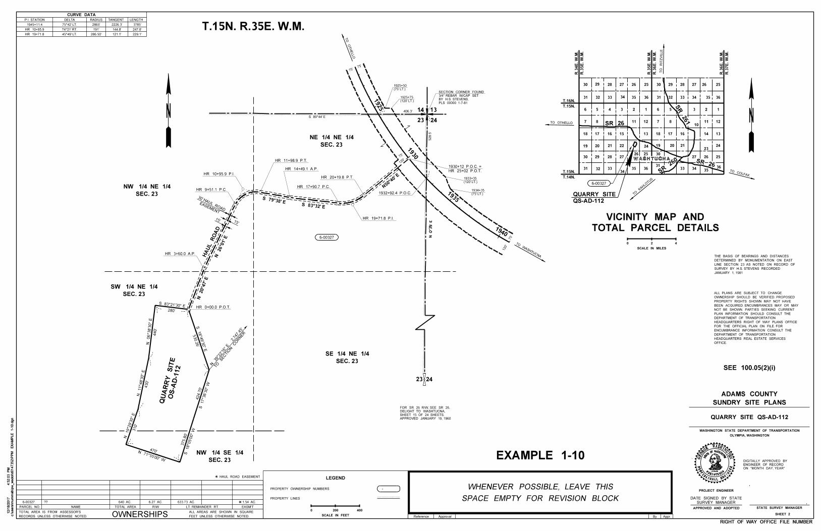
c:\users\m
um
mab\p
w_
wsdot\d0147352\P
PM
EX
AM
PLE 1-1
0.d
gn
4:5
2:0
3 P
M12/1
8/2
017
c:\users\m
um
mab\p
w_
wsdot\d0147352\P
PM
EX
AM
PLE 1-1
0.d
gn
4:5
2:0
3 P
M12/1
8/2
017
By Appr.Reference Approval
OLYMPIA, WASHINGTON
WASHINGTON STATE DEPARTMENT OF TRANSPORTATION
LT. REMAINDER RT. EASM'T
FEET UNLESS OTHERWISE NOTED.
ALL AREAS ARE SHOWN IN SQUARE
LEGEND
PROPERTY OWNERSHIP NUMBERS
PROPERTY LINES
-
SCALE IN FEET
0STATE SURVEY MANAGERPARCEL NO. NAME R/WTOTAL AREA
OWNERSHIPSRECORDS UNLESS OTHERWISE NOTED.
TOTAL AREA IS FROM ASSESSOR'S
12345
WOFWASHINGTON
GISTERED
ONAL ENGI
NEER
ASHINGTNO
PROJECT ENGINEER
STAT
E
RE
PROFESSI
GEOR
GE
APPROVED AND ADOPTED
RIGHT OF WAY OFFICE FILE NUMBERRIGHT OF WAY OFFICE FILE NUMBER
SHEET 2
SUNDRY SITE PLANS
ADAMS COUNTY
QUARRY SITE QS-AD-112
0
TOTAL PARCEL DETAILS
VICINITY MAP AND
200 400
30 29 28 27 26 25 30 29 28 27 2526
35 3634333231363534333231
6 5 4 3 2 1 6 5 3 2 1
121110
87121187
18 17 16 15 13 18 16 14 13
2423
27 26 25
3635
3433
212019
3025
24
3635
20
2930
31 32 3334
2728
6-00327
R.3
4E.
W.M.
R.3
5E.
W.M.
R.3
5E.
W.M.
R.3
6E.
W.M.
R.3
6E.
W.M.
R.3
7E.
W.M.
T.16N.
T.15N.
T.15N.
T.14N.
TO
RIT
ZVIL
LE
SCALE IN MILES
2 4
31
WASHTUCNASR 26
SR 26
0
SR 26
SR 261
2221
26
19
QS-AD-112
QUARRY SITE
SEC. 23
NE 1/4 NE 1/4
14
23 24
13
T.15N. R.35E. W.M.
CURVE DATA
P.I. STATION DELTA RADIUS TANGENT LENGTH
286.50'
1945+11.4
HR 10+95.9
HR 19+71.8
75°42' LT.
74°21' RT.
45°49' LT.
2865'
191'
2226.3'
144.8'
121.1'
3785'
247.8'
229.1'
SEC. 23
SE 1/4 NE 1/4
SEC. 23
NW 1/4 SE 1/4
406.3'
HA
UL R
OA
D
528.5'
N 0°35'
E
75'
120'
280'
440'
430'
310'
470'
530.2
6'
S 18°49'30" E
424.7
0'
S 17°36'30"
W
S 18°05'00"
W
375.8
0'
N 71°55'00" W
N 19°29'30"
E
N 11°48'30"
E
N 06°38'3
0"
E
S 83°21'30" E
SEC. 23
SW 1/4 NE 1/4
OS-A
D-1
12
QU
AR
RY SIT
E
HR 0+00.0 P.O.T.
SEC. 23
NW 1/4 NE 1/4
HR 20+19.8 P.T.
HR 17+90.7 P.C.
HR 14+49.1 A.P.
HR 3+60.0 A.P.
HR 10+95.9 P.I.
HR 9+51.1 P.C.
HR 11+98.9 P.T.
HR 19+71.8 P.I.
TO SECTIO
N C
OR
NER
N 39°2
2'16" E 2,747.45'
15'
15'
EASEMENT
30' HAUL ROAD
6-00327
TO
OT
HE
LL
O
TO WASHTUCNA
APPROVED JANUARY 19, 1960
SHEET 15 OF 24 SHEETS,
DELIGHT TO WASHTUCNA,
FOR SR 26 R/W, SEE SR 26,
SEE 100.05(2)(i)
SURVEY MANAGER
DATE SIGNED BY STATE
TO OTHELLO
TO COLFAX
TO
KAHLO
TUS
PLS 00000 1-7-81
BY H.S. STEVENS,
3/4" REBAR W/CAP SET
SECTION CORNER FOUND
SPACE EMPTY FOR REVISION BLOCK
WHENEVER POSSIBLE, LEAVE THIS
EXAMPLE 1-10ON "MONTH DAY, YEAR"
ENGINEER OF RECORD
DIGITALLY APPROVED BY
75'
75'
75'
120'
HAUL ROAD EASEMENT
6-00327 640 AC. 6.27 AC. 633.73 AC. 1.54 AC.??
OFFICE.
HEADQUARTERS REAL ESTATE SERVICES
DEPARTMENT OF TRANSPORTATION
ENCUMBRANCE INFORMATION CONSULT THE
FOR THE OFFICIAL PLAN ON FILE. FOR
HEADQUARTERS RIGHT OF WAY PLANS OFFICE
DEPARTMENT OF TRANSPORTATION
PLAN INFORMATION SHOULD CONSULT THE
NOT BE SHOWN. PARTIES SEEKING CURRENT
BEEN ACQUIRED. ENCUMBRANCES MAY OR MAY
PROPERTY RIGHTS SHOWN MAY NOT HAVE
OWNERSHIP SHOULD BE VERIFIED. PROPOSED
ALL PLANS ARE SUBJECT TO CHANGE.
17
1930
1940
1925
1935
HR 25+02 P.O.T.
1930+12 P.O.C. =
1932+92.4 P.O.C.
(75' LT.)
1925+50
(120' LT.)
1925+75
(120' LT.)
1933+35
(75' LT.)
1934+35
23 24
JANUARY 1, 1981
SURVEY BY H.S. STEVENS RECORDED
LINE SECTION 23 AS NOTED ON RECORD OF
DETERMINED BY MONUMENTATION ON EAST
THE BASIS OF BEARINGS AND DISTANCES
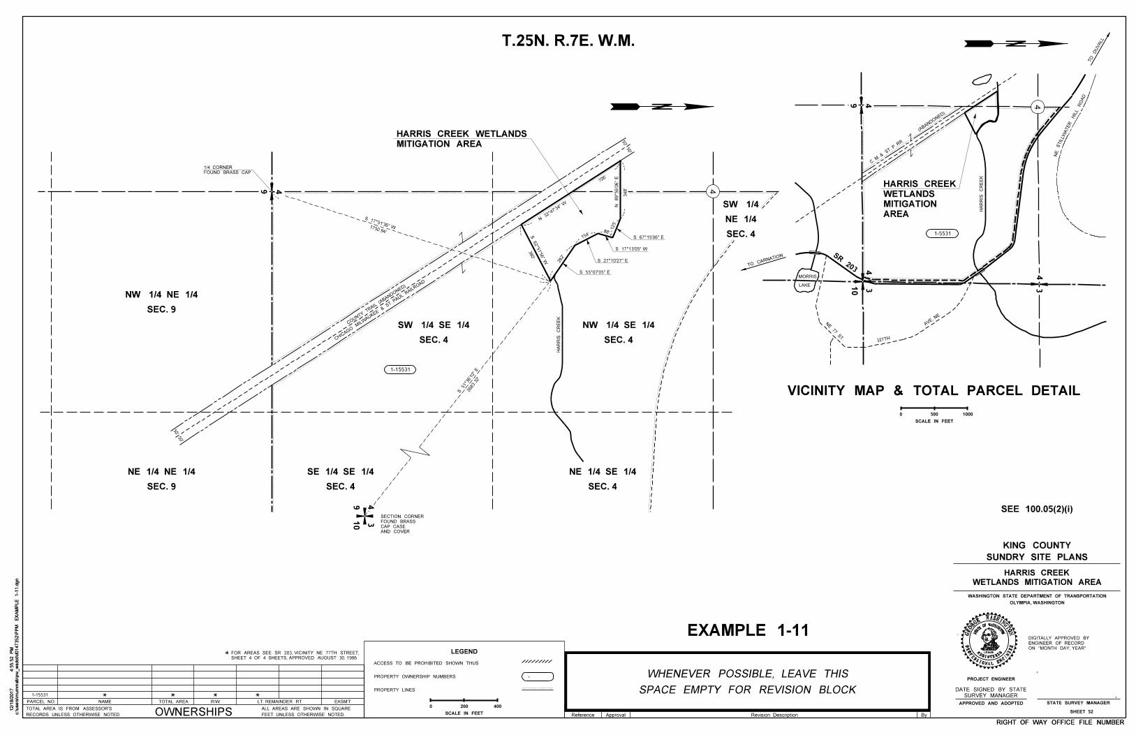
c:\users\m
um
mab\p
w_
wsdot\d0147352\P
PM
EX
AM
PLE 1-1
1.d
gn
4:5
5:5
2 P
M12/1
8/2
017
c:\users\m
um
mab\p
w_
wsdot\d0147352\P
PM
EX
AM
PLE 1-1
1.d
gn
4:5
5:5
2 P
M12/1
8/2
017
OLYMPIA, WASHINGTON
WASHINGTON STATE DEPARTMENT OF TRANSPORTATION
STATE SURVEY MANAGER
12345
WOFWASHINGTON
GISTERED
ONAL ENGI
NEER
ASHINGTNO
PROJECT ENGINEER
STAT
E
RE
PROFESSI
GEOR
GE
APPROVED AND ADOPTED
RIGHT OF WAY OFFICE FILE NUMBERRIGHT OF WAY OFFICE FILE NUMBER
SHEET 52
SUNDRY SITE PLANS
KING COUNTY
WETLANDS MITIGATION AREA
HARRIS CREEK
Reference Approval By
SURVEY MANAGER
DATE SIGNED BY STATE
SCALE IN FEET
0
50'50'
50'50'
PARCEL NO. NAME R/WTOTAL AREA LT. REMAINDER RT. EASM'T
OWNERSHIPSRECORDS UNLESS OTHERWISE NOTED.
TOTAL AREA IS FROM ASSESSOR'S
FEET UNLESS OTHERWISE NOTED.
ALL AREAS ARE SHOWN IN SQUARE
ON "MONTH DAY, YEAR"
ENGINEER OF RECORD
DIGITALLY APPROVED BY
SEE 100.05(2)(i)
T.25N. R.7E. W.M.
Revision Description
500 1000
VICINITY MAP & TOTAL PARCEL DETAIL
SR 203
327TH
1-5531
(ABANDO
NED)
C. M. & S
T. P. R
R
AREA
MITIGATION
WETLANDS
HARRIS CREEK
43
49
4 10 3
TO CARNATIO
N
MORRIS
LAKE
AVE. N
E
NE 77 S
T.
TO
DU
VALL
SEC. 9
NE 1/4 NE 1/4
SEC. 4
SE 1/4 SE 1/4
SEC. 4
NE 1/4 SE 1/4
SEC. 4
SW 1/4 SE 1/4
SEC. 4
NW 1/4 SE 1/4
49
FOUND BRASS CAP
1/4 CORNER
CHICAG
O
MIL
WAUKEE
& ST. P
AUL RAI
LRO
AD
COUNTY
TRAIL (A
BANDONED)
1-15531
125'
88'
154'
262'
N 32°47'3
4" W
706'
S 27°10'27" E
348'
S 62°51'56" W
380'
1750.94'
S 17°51'36" W
2683.32'
S 51°3
6'10" E
SEC. 4
NE 1/4
SW 1/4
MITIGATION AREA
HARRIS CREEK WETLANDS
4910 3
AND COVER
CAP CASE
FOUND BRASS
SECTION CORNER
1-15531
SHEET 4 OF 4 SHEETS, APPROVED AUGUST 30, 1996
FOR AREAS SEE SR 203, VICINITY NE 77TH STREET,
HA
RRIS
CR
EE
K
HA
RRIS
CR
EE
K
NE
STIL
LW
ATE
RHIL
LR
OA
D
SPACE EMPTY FOR REVISION BLOCK
WHENEVER POSSIBLE, LEAVE THIS
EXAMPLE 1-11
SEC. 9
NW 1/4 NE 1/4
LEGEND
ACCESS TO BE PROHIBITED SHOWN THUS
PROPERTY OWNERSHIP NUMBERS
PROPERTY LINES
-
200 400
SCALE IN FEET
0
N 89°56'0
6"
E
S 67°15'06" E
S 17°13'05" W
S 55°07'05" E
4
4
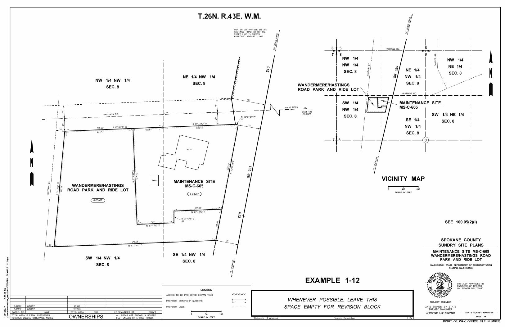
c:\users\m
um
mab\p
w_
wsdot\d0147352\P
PM
EX
AM
PLE 1-1
2.d
gn
5:0
0:5
0 P
M12/1
8/2
017
c:\users\m
um
mab\p
w_
wsdot\d0147352\P
PM
EX
AM
PLE 1-1
2.d
gn
5:0
0:5
0 P
M12/1
8/2
017
OLYMPIA, WASHINGTON
WASHINGTON STATE DEPARTMENT OF TRANSPORTATION
STATE SURVEY MANAGER
12345
WOFWASHINGTON
GISTERED
ONAL ENGI
NEER
ASHINGTNO
PROJECT ENGINEER
STAT
E
RE
PROFESSI
GEOR
GE
APPROVED AND ADOPTED
RIGHT OF WAY OFFICE FILE NUMBERRIGHT OF WAY OFFICE FILE NUMBER
SHEET 14
SUNDRY SITE PLANS
SPOKANE COUNTY
PARK AND RIDE LOT
WANDERMERE/HASTINGS ROAD
MAINTENANCE SITE MS-C-605
T.26N. R.43E. W.M.
SEE 100.05(2)(i)
6
7 8
5 5
8
7 8
SEC. 8
SW 1/4 NE 1/4
MA
YF
AIR
ST.
SEC. 8
NW 1/4
NE 1/4SEC. 8
NW 1/4
NW 1/4
SR 395
SEC. 8
NW 1/4
SW 1/4
MS-C-605
MAINTENANCE SITE
ROAD PARK AND RIDE LOT
WANDERMERE/HASTINGS
SEC. 8
NW 1/4
SE 1/4
TO
SP
OK
AN
E
TO
DE
ER
PA
RK
DA
KO
TA
ST.
SEC. 8
NE 1/4
NW 1/4
HASTINGS RD.
SCALE IN FEET
0 400 800
VICINITY MAP
SURVEY MANAGER
DATE SIGNED BY STATE
390.3
3'
S 5°12'1
2"
W
N 87°43'12" E
548.06'
125'
161.27'
112.9
4'
282.7
2'
317.1
5'
336.08'
233.47'102.61'
242.12'
SHED
BUS.
ROAD PARK AND RIDE LOT
WANDERMERE/HASTINGS MS-C-605
MAINTENANCE SITE
6-03937
6-04097
40'
10'
115'
75'
75'
30'
30'
43'
45'
45'
43'
SEC. 8
NW 1/4 NW 1/4SEC. 8
NE 1/4 NW 1/4
SEC. 8
SE 1/4 NW 1/4
SEC. 8
SW 1/4 NW 1/4
210
215
SR 395
MA
YF
AIR
ST.
HASTINGS RD.
1311.35' (REC.)
CORNER
EAST 1/16
Reference Approval By
LEGEND
ACCESS TO BE PROHIBITED SHOWN THUS
PROPERTY OWNERSHIP NUMBERS
PROPERTY LINES
-
50 100
SCALE IN FEET
0
Revision Description
FARWELL RD.
APPROVED AUGUST 7, 1992.
SHEET 4 OF 15 SHEETS,
HASTINGS ROAD TO MP 172,
FOR SR 395 R/W, SEE SR 395,
SPACE EMPTY FOR REVISION BLOCK
WHENEVER POSSIBLE, LEAVE THIS
EXAMPLE 1-12ON "MONTH DAY, YEAR"
ENGINEER OF RECORD
DIGITALLY APPROVED BY
PARCEL NO. NAME R/WTOTAL AREA LT. REMAINDER RT. EASM'T
OWNERSHIPSRECORDS UNLESS OTHERWISE NOTED.
TOTAL AREA IS FROM ASSESSOR'S
FEET UNLESS OTHERWISE NOTED.
ALL AREAS ARE SHOWN IN SQUARE
WSDOT6-03937
6-04097 WSDOT
122,769
95,940
TO
DE
ER
PA
RK
TO
SP
OK
AN
E
8
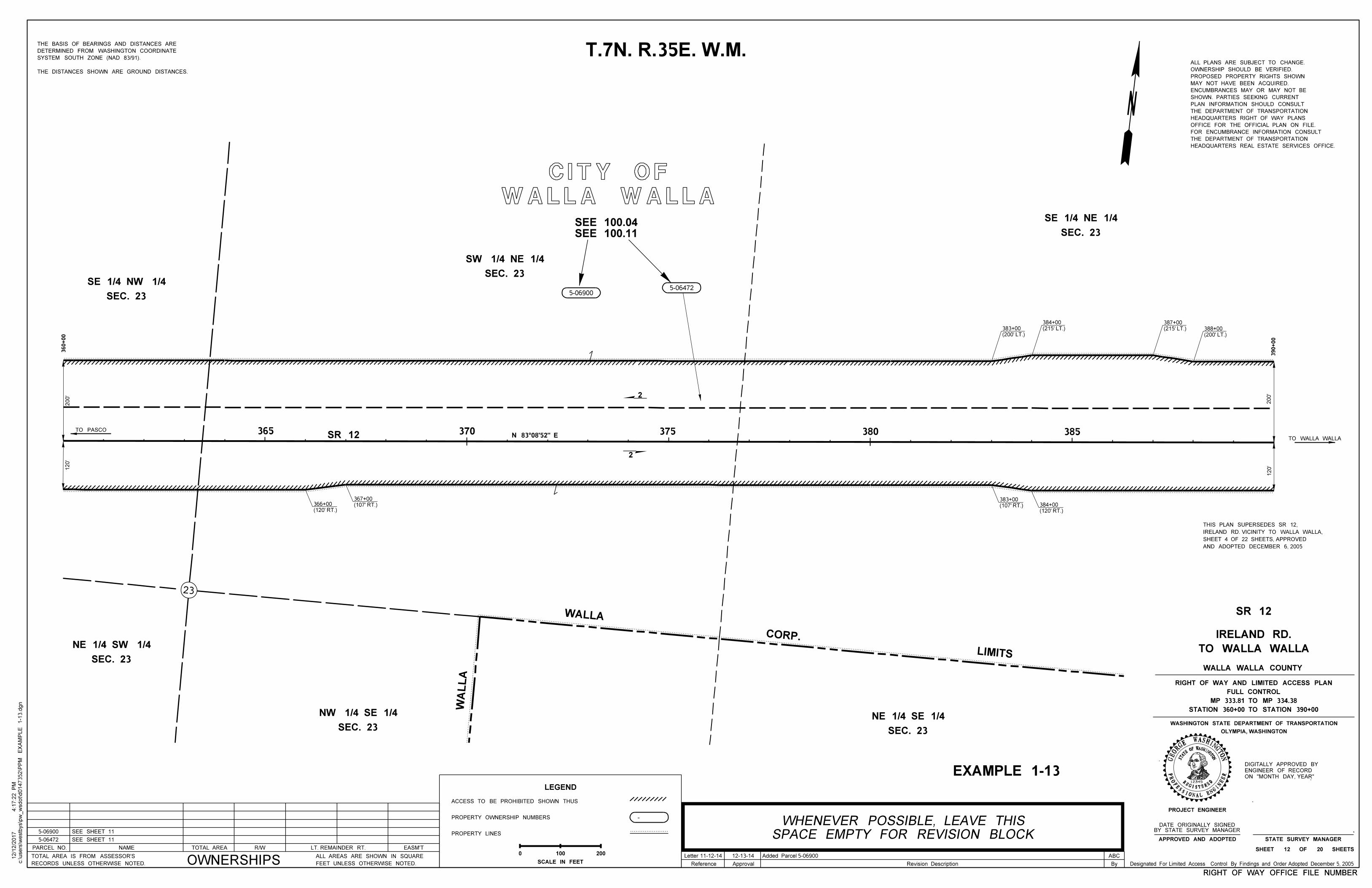
EXAMPLE 1-13
SEE 100.04
RIGHT OF WAY OFFICE FILE NUMBER
T.7N. R.35E. W.M.
WALLA WALLA
CITY OF
TO PASCO
THE DISTANCES SHOWN ARE GROUND DISTANCES.
SYSTEM SOUTH ZONE (NAD 83/91).
DETERMINED FROM WASHINGTON COORDINATE
THE BASIS OF BEARINGS AND DISTANCES ARE
SEC. 23
SE 1/4 NW 1/4SEC. 23
SW 1/4 NE 1/4
5-069005-06472
SEC. 23
SE 1/4 NE 1/4
SEC. 23
NE 1/4 SW 1/4
SEC. 23
NW 1/4 SE 1/4
360+00
200'
120'
SR 12 370N 83°08'52" E
380TO WALLA WALLA
HEADQUARTERS REAL ESTATE SERVICES OFFICE.
THE DEPARTMENT OF TRANSPORTATION
FOR ENCUMBRANCE INFORMATION CONSULT
OFFICE FOR THE OFFICIAL PLAN ON FILE.
HEADQUARTERS RIGHT OF WAY PLANS
THE DEPARTMENT OF TRANSPORTATION
PLAN INFORMATION SHOULD CONSULT
SHOWN. PARTIES SEEKING CURRENT
ENCUMBRANCES MAY OR MAY NOT BE
MAY NOT HAVE BEEN ACQUIRED.
PROPOSED PROPERTY RIGHTS SHOWN
OWNERSHIP SHOULD BE VERIFIED.
ALL PLANS ARE SUBJECT TO CHANGE.
(120' RT.)
366+00 (107' RT.)
367+00
(107' RT.)
383+00
(120' RT.)
384+00
(200' LT.)
388+00 (215' LT.)
387+00
(215' LT.)
384+00
(200' LT.)
383+00
390+00
120'
200'
WA
LL
A
WALLA
CORP.
LIMITS
LEGEND
ACCESS TO BE PROHIBITED SHOWN THUS
PROPERTY OWNERSHIP NUMBERS
PROPERTY LINES
-
100 200
SCALE IN FEET
0
12345
W
STAT
EOFWASHINGTON
REGISTERED
PROFESSIONAL ENGI
NEER
ASHINGTNOGE
OR
GE
ON "MONTH DAY, YEAR"
ENGINEER OF RECORD
DIGITALLY APPROVED BY
Designated For Limited Access Control By Findings and Order Adopted December 5, 2005
RIGHT OF WAY OFFICE FILE NUMBER
2
2
ByReference Approval Revision Description
AND ADOPTED DECEMBER 6, 2005
SHEET 4 OF 22 SHEETS, APPROVED
IRELAND RD. VICINITY TO WALLA WALLA,
THIS PLAN SUPERSEDES SR 12,
5-06900
5-06472
PARCEL NO. NAME R/WTOTAL AREA LT. REMAINDER RT. EASM'T
OWNERSHIPSRECORDS UNLESS OTHERWISE NOTED.
TOTAL AREA IS FROM ASSESSOR'S
FEET UNLESS OTHERWISE NOTED.
ALL AREAS ARE SHOWN IN SQUARE
SEE SHEET 11
SEE SHEET 11
Letter 11-12-14 12-13-14 Added Parcel 5-06900 ABC
SEC. 23
NE 1/4 SE 1/4
375365 385
SEE 100.11
STATE SURVEY MANAGERAPPROVED AND ADOPTED
SHEET 12 OF 20 SHEETS
PROJECT ENGINEER
OLYMPIA, WASHINGTON
WASHINGTON STATE DEPARTMENT OF TRANSPORTATION
TO WALLA WALLA
IRELAND RD.
WALLA WALLA COUNTY
STATION 360+00 TO STATION 390+00
MP 333.81 TO MP 334.38
FULL CONTROL
RIGHT OF WAY AND LIMITED ACCESS PLAN
SR 12
SPACE EMPTY FOR REVISION BLOCK
WHENEVER POSSIBLE, LEAVE THIS BY STATE SURVEY MANAGER
DATE ORIGINALLY SIGNED
c:\users\w
estb
ys\p
w_
wsdot\d0147352\P
PM
EX
AM
PLE 1-1
3.d
gn
4:1
7:2
2 P
M12/1
2/2
017
23
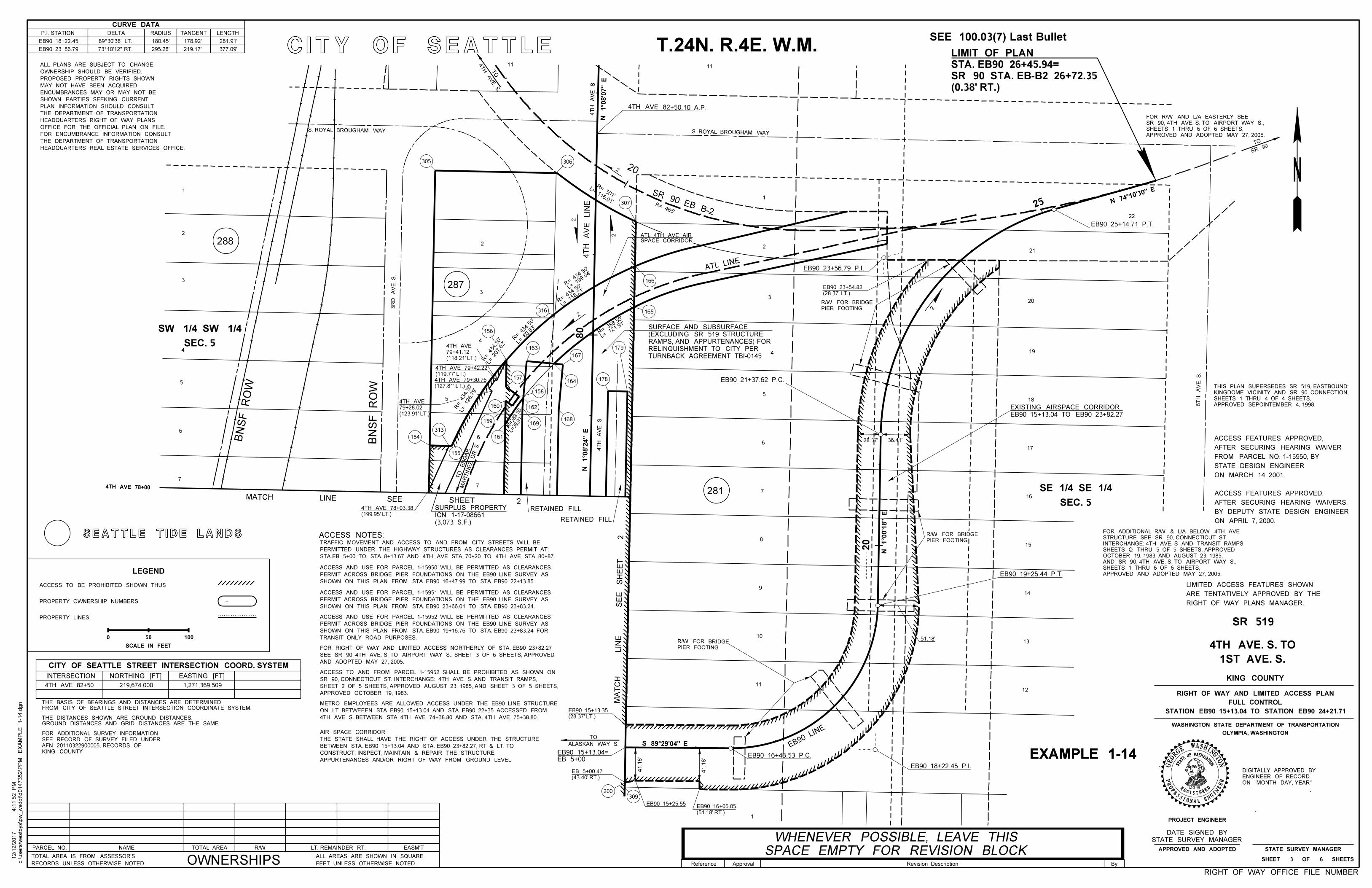
EB90 16+43.53 P.C.
EB90 19+25.44 P.T.
EB90 21+37.62 P.C.
EB90 25+14.71 P.T.
EB90 18+22.45 P.I.
EB90 23+56.79 P.I.
(127.81' LT.)
4TH AVE 79+30.76
(119.77' LT.)
4TH AVE 79+42.22
(199.95' LT.)
4TH AVE 78+03.38 RETAINED FILL
RETAINED FILL
4TH AVE 78+00
11
TURNBACK AGREEMENT TBI-0145
RELINQUISHMENT TO CITY PER
RAMPS, AND APPURTENANCES) FOR
(EXCLUDING SR 519 STRUCTURE,
SURFACE AND SUBSURFACE
EB 5+00
EB90 15+13.04=
(123.91' LT.)
79+28.02
4TH AVE
CITY OF SEATTLE
S 89°29'04" E
4T
H
AV
E
S
1
8
9
10
11
5
4
6
7
1
2
3
6
7
305
200309
(118.21' LT.)
79+41.12
4TH AVE4
ATL LINE
4TH
AVE. S.
TO
MA
RTIN
EZ
DR. S.
TO
ED
GA
R
ALASKAN WAY S.
TO
SR 90
TO
(0.38' RT.)
SR 90 STA. EB-B2 26+72.35
STA. EB90 26+45.94=
LIMIT OF PLAN
EB90 15+13.04 TO EB90 23+82.27
EXISTING AIRSPACE CORRIDOR
288
287
281
1
2
3
5
6
7
S. ROYAL BROUGHAM WAY
4T
H
AV
E
S
S. ROYAL BROUGHAM WAY
22
21
20
19
18
17
15
16
14
13
12
4
5
154
313
155
161
159
160
169168
162
158
157
156
163
164
167
178
179
316 165
166
306
307
4T
H
AV
E. S.
3
2
6T
H
AV
E. S.
3R
D
AV
E. S.
20
20
80
4T
H
AV
E
LIN
E
SR 90 EB B-2
EB90
LINE
25
RIGHT OF WAY PLANS MANAGER.
ARE TENTATIVELY APPROVED BY THE
LIMITED ACCESS FEATURES SHOWN
ON APRIL 7, 2000.
BY DEPUTY STATE DESIGN ENGINEER
AFTER SECURING HEARING WAIVERS,
ACCESS FEATURES APPROVED,
ON MARCH 14, 2001.
STATE DESIGN ENGINEER
FROM PARCEL NO. 1-15950, BY
AFTER SECURING HEARING WAIVER
ACCESS FEATURES APPROVED,
SHOWN ON THIS PLAN FROM STA. EB90 16+47.99 TO STA. EB90 22+13.85.
PERMIT ACROSS BRIDGE PIER FOUNDATIONS ON THE EB90 LINE SURVEY AS
ACCESS AND USE FOR PARCEL 1-15950 WILL BE PERMITTED AS CLEARANCES
SHOWN ON THIS PLAN FROM STA. EB90 23+66.01 TO STA. EB90 23+83.24.
PERMIT ACROSS BRIDGE PIER FOUNDATIONS ON THE EB90 LINE SURVEY AS
ACCESS AND USE FOR PARCEL 1-15951 WILL BE PERMITTED AS CLEARANCES
ACCESS NOTES:
TRANSIT ONLY ROAD PURPOSES.
SHOWN ON THIS PLAN FROM STA. EB90 19+16.76 TO STA. EB90 23+83.24 FOR
PERMIT ACROSS BRIDGE PIER FOUNDATIONS ON THE EB90 LINE SURVEY AS
ACCESS AND USE FOR PARCEL 1-15952 WILL BE PERMITTED AS CLEARANCES
STA.EB 5+00 TO STA. 8+13.67 AND 4TH AVE STA. 70+20 TO 4TH AVE STA. 80+87.
PERMITTED UNDER THE HIGHWAY STRUCTURES AS CLEARANCES PERMIT AT:
TRAFFIC MOVEMENT AND ACCESS TO AND FROM CITY STREETS WILL BE
4TH AVE S. BETWEEN STA. 4TH AVE 74+38.80 AND STA. 4TH AVE 75+38.80.
ON LT. BETWEEEN STA. EB90 15+13.04 AND STA. EB90 22+35 ACCESSED FROM
METRO EMPLOYEES ARE ALLOWED ACCESS UNDER THE EB90 LINE STRUCTURE
APPURTENANCES AND/OR RIGHT OF WAY FROM GROUND LEVEL.
CONSTRUCT, INSPECT, MAINTAIN & REPAIR THE STRUCTURE
BETWEEN STA. EB90 15+13.04 AND STA. EB90 23+82.27, RT. & LT. TO
THE STATE SHALL HAVE THE RIGHT OF ACCESS UNDER THE STRUCTURE
AIR SPACE CORRIDOR:
AND ADOPTED MAY 27, 2005.
SEE SR 90 4TH AVE. S. TO AIRPORT WAY S., SHEET 3 OF 6 SHEETS, APPROVED
FOR RIGHT OF WAY AND LIMITED ACCESS NORTHERLY OF STA. EB90 23+82.27
APPROVED OCTOBER 19, 1983.
SHEET 2 OF 5 SHEETS, APPROVED AUGUST 23, 1985, AND SHEET 3 OF 5 SHEETS,
SR 90, CONNECTICUT ST. INTERCHANGE: 4TH AVE S. AND TRANSIT RAMPS,
ACCESS TO AND FROM PARCEL 1-15952 SHALL BE PROHIBITED AS SHOWN ON
SEE 100.03(7) Last Bullet
EXAMPLE 1-14EXAMPLE 1-14
APPROVED SEPOINTEMBER 4, 1998.
SHEETS 1 THRU 4 OF 4 SHEETS,
KINGDOME VICINITY AND SR 90 CONNECTION,
THIS PLAN SUPERSEDES SR 519, EASTBOUND:
RIGHT OF WAY OFFICE FILE NUMBER
N 1°0
8'0
7" E
N 74°1
0'30" E
N 1°0
8'2
4" E
N 1°0
0'1
8" E
PIER FOOTING
R/W FOR BRIDGE
PIER FOOTING
R/W FOR BRIDGE
PIER FOOTING
R/W FOR BRIDGE
4TH AVE 82+50.10 A.P.
R= 465'
R= 501'
L= 116.01'
R=
434.50'
L= 1
99.04'
R=
434.50'
L= 1
18.21'
R=
434.50'
L= 8
0.83'
R= 434.50'
L= 207.62'
L= 126.79'
R= 434.50'
R=388.50
L=39.91
L= 1
21.91'
R= 38
8.50'
2
2
(3,073 S.F.)
ICN 1-17-08661
SURPLUS PROPERTY
EB90 15+25.55
41.1
8'
41.1
8'
(51.18' RT.)
EB90 16+05.05
51.18'
36.41'28.37'
(28.37' LT.)
EB90 23+54.82
(28.37' LT.)
EB90 15+13.35
(43.40' RT.)
EB 5+00.47
SEC. 5
SW 1/4 SW 1/4
LEGEND
ACCESS TO BE PROHIBITED SHOWN THUS
PROPERTY OWNERSHIP NUMBERS
PROPERTY LINES
-
50 100
SCALE IN FEET
0
T.24N. R.4E. W.M.
HEADQUARTERS REAL ESTATE SERVICES OFFICE.
THE DEPARTMENT OF TRANSPORTATION
FOR ENCUMBRANCE INFORMATION CONSULT
OFFICE FOR THE OFFICIAL PLAN ON FILE.
HEADQUARTERS RIGHT OF WAY PLANS
THE DEPARTMENT OF TRANSPORTATION
PLAN INFORMATION SHOULD CONSULT
SHOWN. PARTIES SEEKING CURRENT
ENCUMBRANCES MAY OR MAY NOT BE
MAY NOT HAVE BEEN ACQUIRED.
PROPOSED PROPERTY RIGHTS SHOWN
OWNERSHIP SHOULD BE VERIFIED.
ALL PLANS ARE SUBJECT TO CHANGE.
SEC. 5
SE 1/4 SE 1/4
KING COUNTY
AFN 20110322900005, RECORDS OF
SEE RECORD OF SURVEY FILED UNDER
FOR ADDITIONAL SURVEY INFORMATION
PARCEL NO. NAME R/WTOTAL AREA LT. REMAINDER RT. EASM'T
OWNERSHIPSRECORDS UNLESS OTHERWISE NOTED.
TOTAL AREA IS FROM ASSESSOR'S
FEET UNLESS OTHERWISE NOTED.
ALL AREAS ARE SHOWN IN SQUARE
11
APPROVED AND ADOPTED MAY 27, 2005.
SHEETS 1 THRU 6 OF 6 SHEETS,
SR 90, 4TH AVE. S. TO AIRPORT WAY S.,
FOR R/W AND L/A EASTERLY SEE
APPROVED AND ADOPTED MAY 27, 2005.
SHEETS 1 THRU 6 OF 6 SHEETS,
AND SR 90, 4TH AVE. S. TO AIRPORT WAY S.,
OCTOBER 19, 1983 AND AUGUST 23, 1985,
SHEETS Q THRU 5 OF 5 SHEETS, APPROVED
INTERCHANGE: 4TH AVE. S AND TRANSIT RAMPS,
STRUCTURE SEE SR 90, CONNECTICUT ST.
FOR ADDITIONAL R/W & L/A BELOW 4TH AVE
BN
SF
RO
W
BN
SF
RO
W
ON "MONTH DAY, YEAR"
ENGINEER OF RECORD
DIGITALLY APPROVED BY
2
2
2
SPACE CORRIDORATL 4TH AVE AIR
ByReference Approval Revision Description
2
S
HE
ET
S
EE
LIN
EM
AT
CH
2 SHEET SEE LINEMATCH
12345
W
STAT
EOFWASHINGTON
REGISTERED
PROFESSIONAL ENGI
NEER
ASHINGTNOGE
OR
GE
SPACE EMPTY FOR REVISION BLOCK
WHENEVER POSSIBLE, LEAVE THIS
SEATTLE TIDE LANDS
FROM CITY OF SEATTLE STREET INTERSECTION COORDINATE SYSTEM.
THE BASIS OF BEARINGS AND DISTANCES ARE DETERMINED
GROUND DISTANCES AND GRID DISTANCES ARE THE SAME.
THE DISTANCES SHOWN ARE GROUND DISTANCES.
c:\users\w
estb
ys\p
w_
wsdot\d0147352\P
PM
EX
AM
PLE 1-1
4.d
gn
4:1
1:5
2 P
M12/1
2/2
017
CITY OF SEATTLE STREET INTERSECTION COORD. SYSTEM
INTERSECTION NORTHING [FT] EASTING [FT]
4TH AVE 82+50 219,674.000 1,271,369.509
OLYMPIA, WASHINGTON
WASHINGTON STATE DEPARTMENT OF TRANSPORTATION
STATION EB90 15+13.04 TO STATION EB90 24+21.71
FULL CONTROL
RIGHT OF WAY AND LIMITED ACCESS PLAN
KING COUNTY
1ST AVE. S.
4TH AVE. S. TO
SR 519
STATE SURVEY MANAGER
SHEET 3 OF 6 SHEETS
APPROVED AND ADOPTED
PROJECT ENGINEER
CURVE DATA
P.I. STATION DELTA RADIUS TANGENT LENGTH
EB90 18+22.45
EB90 23+56.79 73°10'12" RT.
89°30'38" LT. 180.45' 178.92' 281.91'
295.28' 219.17' 377.09'
STATE SURVEY MANAGER
DATE SIGNED BY
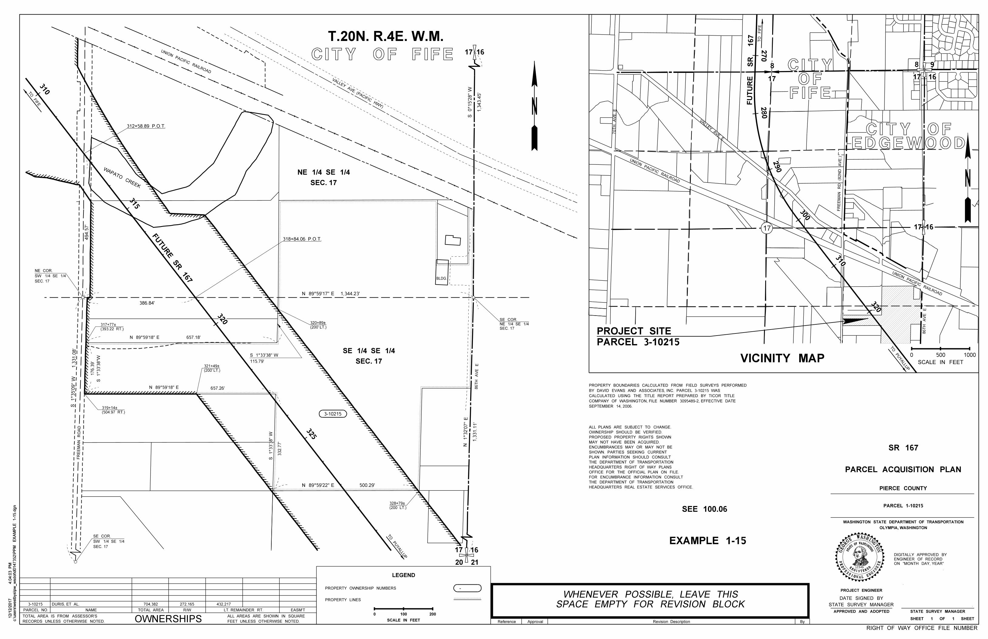
EXAMPLE 1-15
SEE 100.06
RIGHT OF WAY OFFICE FILE NUMBER
310
320
BLDG.
657.18'
657.26'
332.7
7'
N 89°59'18" E
N 89°59'18" E
S 1°33'3
8"
W
LEGEND
PROPERTY OWNERSHIP NUMBERS
PROPERTY LINES
-
100 200
SCALE IN FEET
0
ByReference Approval Revision Description
ON "MONTH DAY, YEAR"
ENGINEER OF RECORD
DIGITALLY APPROVED BY
12345
W
STAT
EOFWASHINGTON
REGISTERED
PROFESSIONAL ENGI
NEER
ASHINGTNOGE
OR
GE
T.20N. R.4E. W.M.
VALLEY AVE. (PACIFIC HWY)
17 16
1,3
43.4
5'
S 0°15'2
8"
W
SEC. 17
NE 1/4 SE 1/4
SEC. 17
SE 1/4 SE 1/4
325
315
N 89°59'22" E 500.29'
176.3
9'
386.84'
S 1°33'3
8"W
1,3
31.1
1'
N 1°32'0
7"
E
494.5
7'
S 1°35'0
9"
W
1,3
31.0
8'
115.79'
S 1°33'38" W
SPACE EMPTY FOR REVISION BLOCK
WHENEVER POSSIBLE, LEAVE THIS
VICINITY MAP
PARCEL 3-10215
PROJECT SITE
FUTU
RE SR 167
N 89°59'17" E 1,344.23'
17
20 21
16
FR
EE
MA
N
RO
AD
(504.97 RT.)
319+14À
(200' LT.)
321+49À
(200 LT.)
328+79À
(393.22 RT.)
317+77À
318+84.06 P.O.T.
312+58.89 P.O.T.
(200' LT.)
320+89À
SEPTEMBER 14, 2006.
COMPANY OF WASHINGTON, FILE NUMBER 3095489-2, EFFECTIVE DATE
CALCULATED USING THE TITLE REPORT PREPARED BY TICOR TITLE
BY DAVID EVANS AND ASSOCIATES, INC. PARCEL 3-10215 WAS
PROPERTY BOUNDARIES CALCULATED FROM FIELD SURVEYS PERFORMED
HEADQUARTERS REAL ESTATE SERVICES OFFICE.
THE DEPARTMENT OF TRANSPORTATION
FOR ENCUMBRANCE INFORMATION CONSULT
OFFICE FOR THE OFFICIAL PLAN ON FILE.
HEADQUARTERS RIGHT OF WAY PLANS
THE DEPARTMENT OF TRANSPORTATION
PLAN INFORMATION SHOULD CONSULT
SHOWN. PARTIES SEEKING CURRENT
ENCUMBRANCES MAY OR MAY NOT BE
MAY NOT HAVE BEEN ACQUIRED.
PROPOSED PROPERTY RIGHTS SHOWN
OWNERSHIP SHOULD BE VERIFIED.
ALL PLANS ARE SUBJECT TO CHANGE.
EDGEWOODCITY OF
FIFEOF
CITY
FU
TU
RE
SR 167
UNION PACIFIC RAILROAD
UNION PACIFIC RAILROAD
UNION PACIFIC RAILROAD
VALLE
Y AVE. E
70T
H
AV
E. E
FR
EE
MA
N
RD (8
2N
D
AV
E.)
500 1000
SCALE IN FEET
0
17 16
8
17 16
98
17
WAPATO CREEK
3-10215
3-10215
PARCEL NO. NAME R/WTOTAL AREA LT. REMAINDER RT. EASM'T
OWNERSHIPSRECORDS UNLESS OTHERWISE NOTED.
TOTAL AREA IS FROM ASSESSOR'S
FEET UNLESS OTHERWISE NOTED.
ALL AREAS ARE SHOWN IN SQUARE
DURIS, ET AL.
704,382
272,165
432,217
CITY OF FIFE
c:\users\w
estb
ys\p
w_
wsdot\d0147352\P
PM
EX
AM
PLE 1-1
5.d
gn
4:0
4:0
3 P
M12/1
2/2
017
c:\users\w
estb
ys\p
w_
wsdot\d0147352\P
PM
EX
AM
PLE 1-1
5.d
gn
4:0
4:0
3 P
M12/1
2/2
017
86T
H
AV
E
E
86T
H
AV
E
E
TO FIF
E
TO P
UY
ALLUP
TO P
UY
ALLUP
TO
FIF
E
310
320
300
290
280
270
SEC. 17
SW 1/4 SE 1/4
NE COR.
SEC. 17
SW 1/4 SE 1/4
SE COR.
SEC. 17
NE 1/4 SE 1/4
SE COR.
STATE SURVEY MANAGER
DATE SIGNED BY
OLYMPIA, WASHINGTON
WASHINGTON STATE DEPARTMENT OF TRANSPORTATION
PARCEL ACQUISITION PLAN
PIERCE COUNTY
PARCEL 1-10215
SR 167
PROJECT ENGINEER
APPROVED AND ADOPTED STATE SURVEY MANAGER
SHEET 1 OF 1 SHEET
17
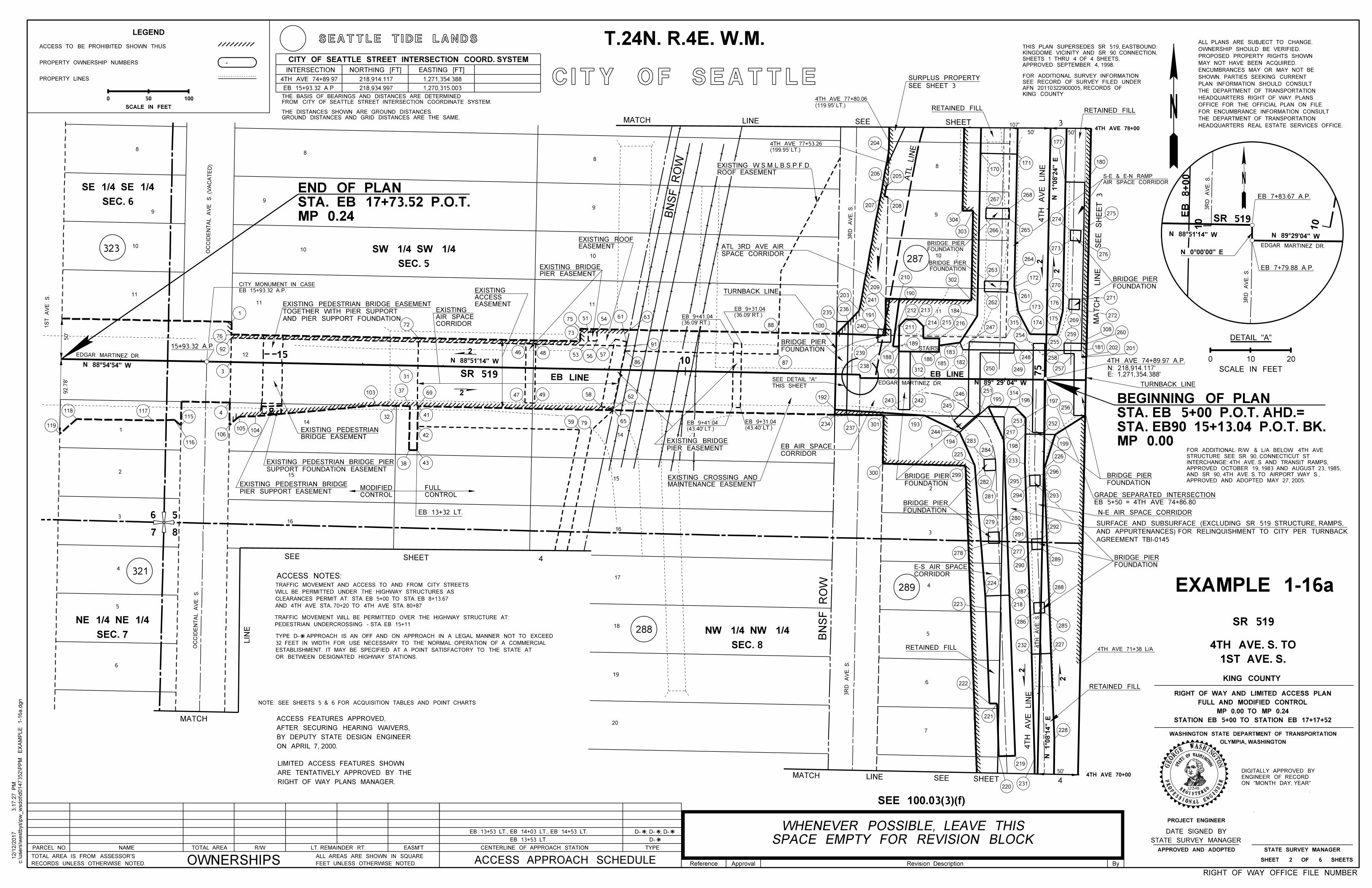
10
EB 7+79.88 A.P.
92.7
8'
50'
TURNBACK LINE
RETAINED FILL
CORRIDOR
E-S AIR SPACE
STAIRS
SPACE CORRIDOR
ATL 3RD AVE AIR
4TH AVE 74+89.97 A.P.
TURNBACK LINE
3R
D
AV
E. S.
3R
D
AV
E. S.
EDGAR MARTINEZ DR.
EB 7+83.67 A.P.
EB 8+00
10
50'50'4TH AVE 78+00
107'
(119.95' LT.)
4TH AVE 77+80.06
MA
TC
H
LIN
E
SE
E
SH
EE
T 3
AGREEMENT TBI-0145
AND APPURTENANCES) FOR RELINQUISHMENT TO CITY PER TURNBACK
SURFACE AND SUBSURFACE (EXCLUDING SR 519 STRUCTURE, RAMPS,
4TH AVE 71+38 L/A
4TH AVE 70+0050'
231220
(199.95' LT.)
4TH AVE 77+53.26
T.24N. R.4E. W.M.
CITY OF SEATTLE
ATL LIN
E
308260
275
276
271
272
201202181
180
SR 519
D- EB 13+53 LT.
PARCEL NO. NAME R/WTOTAL AREA LT. REMAINDER RT. EASM'T
OWNERSHIPSRECORDS UNLESS OTHERWISE NOTED.
TOTAL AREA IS FROM ASSESSOR'S
FEET UNLESS OTHERWISE NOTED.
ALL AREAS ARE SHOWN IN SQUARE
EB 13+53 LT., EB 14+03 LT., EB 14+53 LT. D- , D- , D-
CENTERLINE OF APPROACH STATION TYPE
ACCESS APPROACH SCHEDULE
288
287
289
323
321
11
EDGAR MARTINEZ DR.
OC
CID
EN
TA
L
AV
E
S. (V
AC
AT
ED)
9
1010
11
9
3R
D
AV
E. S.
4T
H
AV
E. S.
18
19
20
16
15
14
11
88
9
8
11
10
SR 519 EB LINEEDGAR MARTINEZ DR.
8
9
10
4T
H
AV
E
LIN
E
5
6
7
3
4
100
235236
203
240
191
241
209
210
190
211
239
238
212 213
214 215 216
184
302
187
188
189
312
186185
262
263
264
172
261
173
174315
254
247
182
183
250 249
248
255
175
259
176
270
269
228
221
222
232 227
285286
288287
218223
224
289
290
278 277
291
292
280279
293294
295
281
282
299300
301237
234
192243 242
193
245
246
194
244
283
284225
233
296
226
217
198
253
251
195
314
196 197
252
256
199
258
257
273
274
265266303
304
267268
177
171
170
207 208
205206
204
17
16
15
14
OC
CID
EN
TA
L
AV
E
S.
12
2
1
3R
D
AV
E. S.
2
1
4T
H
AV
E
LIN
E
1510
EB LINE 75
119
118 117
116
115
106
4
105 104
3
92
76
1
72
31
103
32
37 69
41
42
38 43
88
87
75 51 54 63
73
61
91
86
57565346 48
47 49
59 79
58 62
65
3
219
4
5
6
1S
T
AV
E
S.
RIGHT OF WAY PLANS MANAGER.
ARE TENTATIVELY APPROVED BY THE
LIMITED ACCESS FEATURES SHOWN
ON APRIL 7, 2000.
BY DEPUTY STATE DESIGN ENGINEER
AFTER SECURING HEARING WAIVERS,
ACCESS FEATURES APPROVED,
OR BETWEEN DESIGNATED HIGHWAY STATIONS.
ESTABLISHMENT. IT MAY BE SPECIFIED AT A POINT SATISFACTORY TO THE STATE AT
32 FEET IN WIDTH FOR USE NECESSARY TO THE NORMAL OPERATION OF A COMMERCIAL
TYPE D- APPROACH IS AN OFF AND ON APPROACH IN A LEGAL MANNER NOT TO EXCEED
6
7 8
5
SEE 100.03(3)(f)
LEGEND
ACCESS TO BE PROHIBITED SHOWN THUS
PROPERTY OWNERSHIP NUMBERS
PROPERTY LINES
-
50 100
SCALE IN FEET
0
RIGHT OF WAY OFFICE FILE NUMBER
EXAMPLE 1-16a
N 89°29'04" W
N 0°00'00" E
N 88°51'14" W
N 88°51'14" W
N 89° 29' 04" W
N 1°0
8'1
4" E
N 1°0
8'2
4" E
N 88°54'54" W
CONTROL
MODIFIED
CONTROL
FULL
EB 13+32 LT.
THIS SHEET
SEE DETAIL "A"
2
FOUNDATION
BRIDGE PIER
CORRIDOR
EB AIR SPACE
FOUNDATION
BRIDGE PIER
FOUNDATION
BRIDGE PIER
N-E AIR SPACE CORRIDOR
FOUNDATION
BRIDGE PIER
RETAINED FILLRETAINED FILL
FOUNDATION
BRIDGE PIER
FOUNDATION
BRIDGE PIER
AIR SPACE CORRIDOR
S-E & E-N RAMP
FOUNDATION
BRIDGE PIER
RETAINED FILL
FOUNDATION
BRIDGE PIER
ROOF EASEMENT
EXISTING W.S.M.L.B.S.P.F.D.
AND PIER SUPPORT FOUNDATION
TOGETHER WITH PIER SUPPORT
EXISTING PEDESTRIAN BRIDGE EASEMENT
CORRIDOR
AIR SPACE
EXISTINGEASEMENT
ACCESS
EXISTING
PIER EASEMENT
EXISTING BRIDGE
EASEMENT
EXISTING ROOF
PIER EASEMENT
EXISTING BRIDGEBRIDGE EASEMENT
EXISTING PEDESTRIAN
SUPPORT FOUNDATION EASEMENT
EXISTING PEDESTRIAN BRIDGE PIER
PIER SUPPORT EASEMENT
EXISTING PEDESTRIAN BRIDGE MAINTENANCE EASEMENT
EXISTING CROSSING AND
MP 0.00
STA. EB90 15+13.04 P.O.T. BK.
STA. EB 5+00 P.O.T. AHD.=
BEGINNING OF PLAN
MP 0.24
STA. EB 17+73.52 P.O.T.
END OF PLAN
BN
SF
RO
W
BN
SF
RO
W
SCALE IN FEET
0 10 20
APPROVED SEPTEMBER 4, 1998.
SHEETS 1 THRU 4 OF 4 SHEETS,
KINGDOME VICINITY AND SR 90 CONNECTION,
THIS PLAN SUPERSEDES SR 519, EASTBOUND:
3 SHEET SEE LINEMATCH
SEE SHEET 3
SURPLUS PROPERTY
SEC. 7
NE 1/4 NE 1/4
SEC. 5
SW 1/4 SW 1/4
SEC. 8
NW 1/4 NW 1/4
SEC. 6
SE 1/4 SE 1/4
SEATTLE TIDE LANDS
MATCH
LIN
E
4 SHEETSEE
4SHEET SEE LINEMATCH
HEADQUARTERS REAL ESTATE SERVICES OFFICE.
THE DEPARTMENT OF TRANSPORTATION
FOR ENCUMBRANCE INFORMATION CONSULT
OFFICE FOR THE OFFICIAL PLAN ON FILE.
HEADQUARTERS RIGHT OF WAY PLANS
THE DEPARTMENT OF TRANSPORTATION
PLAN INFORMATION SHOULD CONSULT
SHOWN. PARTIES SEEKING CURRENT
ENCUMBRANCES MAY OR MAY NOT BE
MAY NOT HAVE BEEN ACQUIRED.
PROPOSED PROPERTY RIGHTS SHOWN
OWNERSHIP SHOULD BE VERIFIED.
ALL PLANS ARE SUBJECT TO CHANGE.
APPROVED AND ADOPTED MAY 27, 2005.
AND SR 90, 4TH AVE. S. TO AIRPORT WAY S.,
APPROVED OCTOBER 19, 1983 AND AUGUST 23, 1985,
INTERCHANGE: 4TH AVE. S AND TRANSIT RAMPS,
STRUCTURE SEE SR 90, CONNECTICUT ST.
FOR ADDITIONAL R/W & L/A BELOW 4TH AVE
Ç
Ç Ç Ç
Ç
NOTE: SEE SHEETS 5 & 6 FOR ACQUISITION TABLES AND POINT CHARTS
ACCESS NOTES:
AND 4TH AVE STA. 70+20 TO 4TH AVE STA. 80+87
CLEARANCES PERMIT AT: STA. EB 5+00 TO STA. EB 8+13.67
WILL BE PERMITTED UNDER THE HIGHWAY STRUCTURES AS
TRAFFIC MOVEMENT AND ACCESS TO AND FROM CITY STREETS
PEDESTRIAN UNDERCROSSING - STA. EB 15+11
TRAFFIC MOVEMENT WILL BE PERMITTED OVER THE HIGHWAY STRUCTURE AT:
DETAIL "A"
EB 5+50 = 4TH AVE 74+86.80
GRADE SEPARATED INTERSECTION
E: 1,271,354.388'N: 218,914.117'
15+93.32 A.P.
EB 15+93.32 A.P.
CITY MONUMENT IN CASE
2
2
22
2
2
(43.40' LT.)
EB 9+41.04(43.40' LT.)
EB 9+31.04
(36.09' RT.)
EB 9+41.04 (36.09' RT.)
EB 9+31.04
c:\users\w
estb
ys\p
w_
wsdot\d0147352\P
PM
EX
AM
PLE 1-1
6a.d
gn
3:1
7:2
7 P
M12/1
2/2
017
12345
W
STAT
EOFWASHINGTON
REGISTERED
PROFESSIONAL ENGI
NEER
ASHINGTNOGE
OR
GE
ON "MONTH DAY, YEAR"
ENGINEER OF RECORD
DIGITALLY APPROVED BY
SPACE EMPTY FOR REVISION BLOCK
WHENEVER POSSIBLE, LEAVE THIS
KING COUNTY
AFN 20110322900005, RECORDS OF
SEE RECORD OF SURVEY FILED UNDER
FOR ADDITIONAL SURVEY INFORMATION
GROUND DISTANCES AND GRID DISTANCES ARE THE SAME.
THE DISTANCES SHOWN ARE GROUND DISTANCES.
FROM CITY OF SEATTLE STREET INTERSECTION COORDINATE SYSTEM.
THE BASIS OF BEARINGS AND DISTANCES ARE DETERMINED
CITY OF SEATTLE STREET INTERSECTION COORD. SYSTEM
INTERSECTION NORTHING [FT] EASTING [FT]
4TH AVE 74+89.97
EB 15+93.32 A.P. 218,934.997
218,914.117 1,271,354.388
1,270,315.003
STATE SURVEY MANAGER
DATE SIGNED BY
Reference Revision DescriptionApproval By
SR 519
1ST AVE. S.
4TH AVE. S. TO
KING COUNTY
STATION EB 5+00 TO STATION EB 17+17+52
MP 0.00 TO MP 0.24
FULL AND MODIFIED CONTROL
RIGHT OF WAY AND LIMITED ACCESS PLAN
OLYMPIA, WASHINGTON
WASHINGTON STATE DEPARTMENT OF TRANSPORTATION
STATE SURVEY MANAGER
SHEET 2 OF 6 SHEETS
APPROVED AND ADOPTED
PROJECT ENGINEER
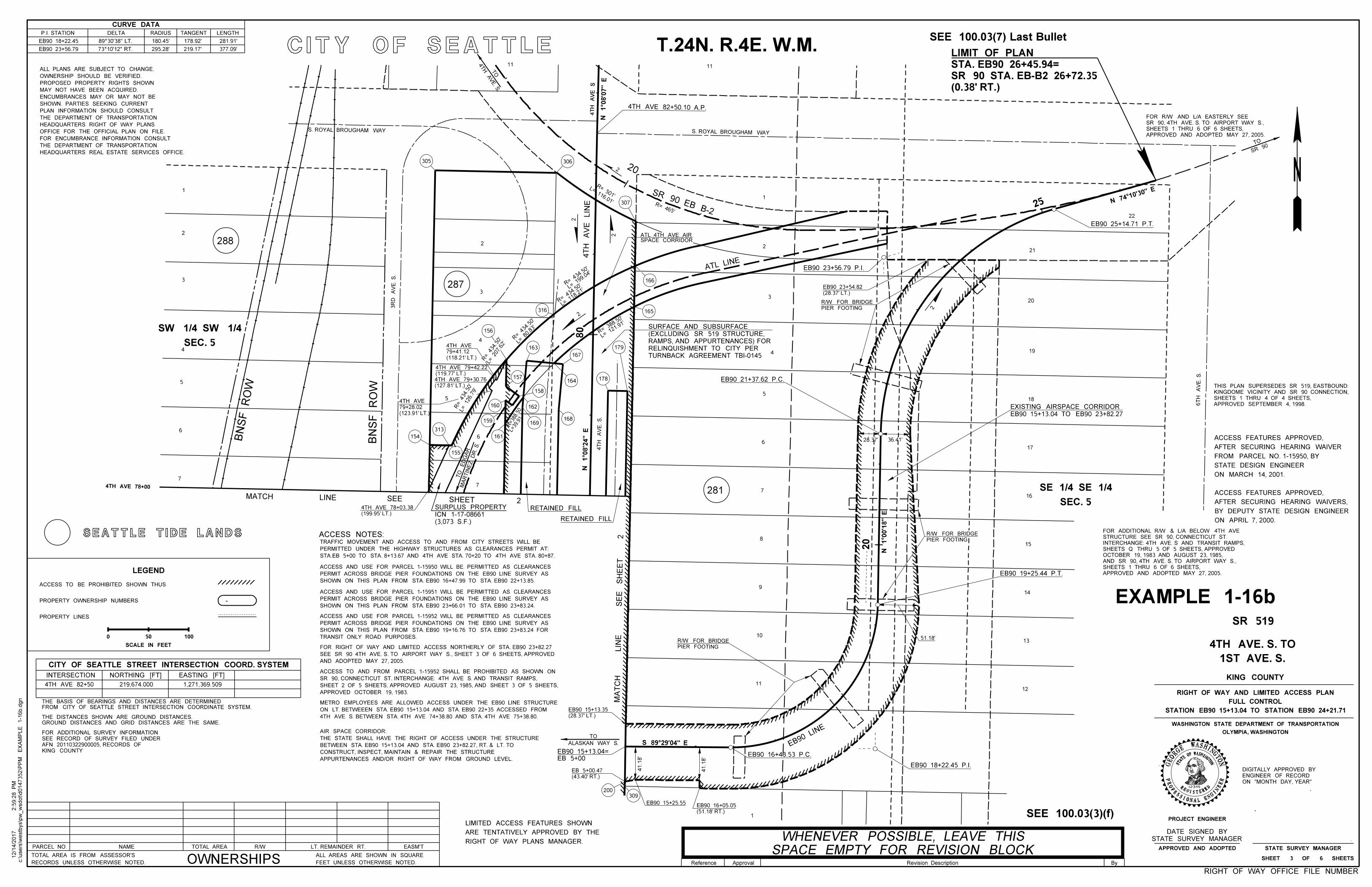
CURVE DATA
P.I. STATION DELTA RADIUS TANGENT LENGTH
EB90 18+22.45
EB90 23+56.79 73°10'12" RT.
89°30'38" LT.
EB90 16+43.53 P.C.
EB90 19+25.44 P.T.
EB90 21+37.62 P.C.
EB90 25+14.71 P.T.
EB90 18+22.45 P.I.
EB90 23+56.79 P.I.
(127.81' LT.)
4TH AVE 79+30.76
(119.77' LT.)
4TH AVE 79+42.22
(199.95' LT.)
4TH AVE 78+03.38 RETAINED FILL
RETAINED FILL
4TH AVE 78+00
180.45' 178.92' 281.91'
295.28' 219.17' 377.09'
11
TURNBACK AGREEMENT TBI-0145
RELINQUISHMENT TO CITY PER
RAMPS, AND APPURTENANCES) FOR
(EXCLUDING SR 519 STRUCTURE,
SURFACE AND SUBSURFACE
EB 5+00
EB90 15+13.04=
(123.91' LT.)
79+28.02
4TH AVE
CITY OF SEATTLE
S 89°29'04" E
4T
H
AV
E
S
1
8
9
10
11
5
4
6
7
1
2
3
6
7
305
200309
(118.21' LT.)
79+41.12
4TH AVE4
ATL LINE
4TH
AVE. S.
TO
MA
RTIN
EZ
DR. S.
TO
ED
GA
R
ALASKAN WAY S.
TO
SR 90
TO
(0.38' RT.)
SR 90 STA. EB-B2 26+72.35
STA. EB90 26+45.94=
LIMIT OF PLAN
EB90 15+13.04 TO EB90 23+82.27
EXISTING AIRSPACE CORRIDOR
288
287
281
1
2
3
5
6
7
S. ROYAL BROUGHAM WAY
4T
H
AV
E
S
S. ROYAL BROUGHAM WAY
22
21
20
19
18
17
15
16
14
13
12
4
5
154
313
155
161
159
160
169168
162
158
157
156
163
164
167
178
179
316 165
166
306
307
4T
H
AV
E. S.
3
2
6T
H
AV
E. S.
3R
D
AV
E. S.
20
20
80
4T
H
AV
E
LIN
E
SR 90 EB B-2
EB90
LINE
25
RIGHT OF WAY PLANS MANAGER.
ARE TENTATIVELY APPROVED BY THE
LIMITED ACCESS FEATURES SHOWN
ON APRIL 7, 2000.
BY DEPUTY STATE DESIGN ENGINEER
AFTER SECURING HEARING WAIVERS,
ACCESS FEATURES APPROVED,
ON MARCH 14, 2001.
STATE DESIGN ENGINEER
FROM PARCEL NO. 1-15950, BY
AFTER SECURING HEARING WAIVER
ACCESS FEATURES APPROVED,
SHOWN ON THIS PLAN FROM STA. EB90 16+47.99 TO STA. EB90 22+13.85.
PERMIT ACROSS BRIDGE PIER FOUNDATIONS ON THE EB90 LINE SURVEY AS
ACCESS AND USE FOR PARCEL 1-15950 WILL BE PERMITTED AS CLEARANCES
SHOWN ON THIS PLAN FROM STA. EB90 23+66.01 TO STA. EB90 23+83.24.
PERMIT ACROSS BRIDGE PIER FOUNDATIONS ON THE EB90 LINE SURVEY AS
ACCESS AND USE FOR PARCEL 1-15951 WILL BE PERMITTED AS CLEARANCES
ACCESS NOTES:
TRANSIT ONLY ROAD PURPOSES.
SHOWN ON THIS PLAN FROM STA. EB90 19+16.76 TO STA. EB90 23+83.24 FOR
PERMIT ACROSS BRIDGE PIER FOUNDATIONS ON THE EB90 LINE SURVEY AS
ACCESS AND USE FOR PARCEL 1-15952 WILL BE PERMITTED AS CLEARANCES
STA.EB 5+00 TO STA. 8+13.67 AND 4TH AVE STA. 70+20 TO 4TH AVE STA. 80+87.
PERMITTED UNDER THE HIGHWAY STRUCTURES AS CLEARANCES PERMIT AT:
TRAFFIC MOVEMENT AND ACCESS TO AND FROM CITY STREETS WILL BE
4TH AVE S. BETWEEN STA. 4TH AVE 74+38.80 AND STA. 4TH AVE 75+38.80.
ON LT. BETWEEEN STA. EB90 15+13.04 AND STA. EB90 22+35 ACCESSED FROM
METRO EMPLOYEES ARE ALLOWED ACCESS UNDER THE EB90 LINE STRUCTURE
APPURTENANCES AND/OR RIGHT OF WAY FROM GROUND LEVEL.
CONSTRUCT, INSPECT, MAINTAIN & REPAIR THE STRUCTURE
BETWEEN STA. EB90 15+13.04 AND STA. EB90 23+82.27, RT. & LT. TO
THE STATE SHALL HAVE THE RIGHT OF ACCESS UNDER THE STRUCTURE
AIR SPACE CORRIDOR:
AND ADOPTED MAY 27, 2005.
SEE SR 90 4TH AVE. S. TO AIRPORT WAY S., SHEET 3 OF 6 SHEETS, APPROVED
FOR RIGHT OF WAY AND LIMITED ACCESS NORTHERLY OF STA. EB90 23+82.27
APPROVED OCTOBER 19, 1983.
SHEET 2 OF 5 SHEETS, APPROVED AUGUST 23, 1985, AND SHEET 3 OF 5 SHEETS,
SR 90, CONNECTICUT ST. INTERCHANGE: 4TH AVE S. AND TRANSIT RAMPS,
ACCESS TO AND FROM PARCEL 1-15952 SHALL BE PROHIBITED AS SHOWN ON
SEE 100.03(7) Last Bullet
RIGHT OF WAY OFFICE FILE NUMBER
N 1°0
8'0
7" E
N 74°1
0'30" E
N 1°0
8'2
4" E
N 1°0
0'1
8" E
PIER FOOTING
R/W FOR BRIDGE
PIER FOOTING
R/W FOR BRIDGE
PIER FOOTING
R/W FOR BRIDGE
4TH AVE 82+50.10 A.P.
R= 465'
R= 501'
L= 116.01'
R=
434.50'
L= 1
99.04'
R=
434.50'
L= 1
18.21'
R=
434.50'
L= 8
0.83'
R= 434.50'
L= 207.62'
L= 126.79'
R= 434.50'
R=388.50
L=39.91
L= 1
21.91'
R= 38
8.50'
2
2
(3,073 S.F.)
ICN 1-17-08661
SURPLUS PROPERTY
EB90 15+25.55
41.1
8'
41.1
8'
(51.18' RT.)
EB90 16+05.05
51.18'
36.41'28.37'
(28.37' LT.)
EB90 23+54.82
(28.37' LT.)
EB90 15+13.35
(43.40' RT.)
EB 5+00.47
SEC. 5
SW 1/4 SW 1/4
LEGEND
ACCESS TO BE PROHIBITED SHOWN THUS
PROPERTY OWNERSHIP NUMBERS
PROPERTY LINES
-
50 100
SCALE IN FEET
0
T.24N. R.4E. W.M.
HEADQUARTERS REAL ESTATE SERVICES OFFICE.
THE DEPARTMENT OF TRANSPORTATION
FOR ENCUMBRANCE INFORMATION CONSULT
OFFICE FOR THE OFFICIAL PLAN ON FILE.
HEADQUARTERS RIGHT OF WAY PLANS
THE DEPARTMENT OF TRANSPORTATION
PLAN INFORMATION SHOULD CONSULT
SHOWN. PARTIES SEEKING CURRENT
ENCUMBRANCES MAY OR MAY NOT BE
MAY NOT HAVE BEEN ACQUIRED.
PROPOSED PROPERTY RIGHTS SHOWN
OWNERSHIP SHOULD BE VERIFIED.
ALL PLANS ARE SUBJECT TO CHANGE.
SEC. 5
SE 1/4 SE 1/4
KING COUNTY
AFN 20110322900005, RECORDS OF
SEE RECORD OF SURVEY FILED UNDER
FOR ADDITIONAL SURVEY INFORMATION
PARCEL NO. NAME R/WTOTAL AREA LT. REMAINDER RT. EASM'T
OWNERSHIPSRECORDS UNLESS OTHERWISE NOTED.
TOTAL AREA IS FROM ASSESSOR'S
FEET UNLESS OTHERWISE NOTED.
ALL AREAS ARE SHOWN IN SQUARE
11
APPROVED AND ADOPTED MAY 27, 2005.
SHEETS 1 THRU 6 OF 6 SHEETS,
SR 90, 4TH AVE. S. TO AIRPORT WAY S.,
FOR R/W AND L/A EASTERLY SEE
APPROVED AND ADOPTED MAY 27, 2005.
SHEETS 1 THRU 6 OF 6 SHEETS,
AND SR 90, 4TH AVE. S. TO AIRPORT WAY S.,
OCTOBER 19, 1983 AND AUGUST 23, 1985,
SHEETS Q THRU 5 OF 5 SHEETS, APPROVED
INTERCHANGE: 4TH AVE. S AND TRANSIT RAMPS,
STRUCTURE SEE SR 90, CONNECTICUT ST.
FOR ADDITIONAL R/W & L/A BELOW 4TH AVE
BN
SF
RO
W
BN
SF
RO
W
ON "MONTH DAY, YEAR"
ENGINEER OF RECORD
DIGITALLY APPROVED BY
2
2
2
SPACE CORRIDORATL 4TH AVE AIR
ByReference Approval Revision Description
2
S
HE
ET
S
EE
LIN
EM
AT
CH
2 SHEET SEE LINEMATCH
12345
W
STAT
EOFWASHINGTON
REGISTERED
PROFESSIONAL ENGI
NEER
ASHINGTNOGE
OR
GE
SPACE EMPTY FOR REVISION BLOCK
WHENEVER POSSIBLE, LEAVE THIS
SEATTLE TIDE LANDS
FROM CITY OF SEATTLE STREET INTERSECTION COORDINATE SYSTEM.
THE BASIS OF BEARINGS AND DISTANCES ARE DETERMINED
GROUND DISTANCES AND GRID DISTANCES ARE THE SAME.
THE DISTANCES SHOWN ARE GROUND DISTANCES.
c:\users\w
estb
ys\p
w_
wsdot\d0147352\P
PM
EX
AM
PLE 1-1
6b.d
gn
2:5
9:2
8 P
M12/1
4/2
017
CITY OF SEATTLE STREET INTERSECTION COORD. SYSTEM
INTERSECTION NORTHING [FT] EASTING [FT]
4TH AVE 82+50 219,674.000 1,271,369.509
SEE 100.03(3)(f)
EXAMPLE 1-16b
STATE SURVEY MANAGER
DATE SIGNED BY
SR 519
1ST AVE. S.
4TH AVE. S. TO
KING COUNTY
STATION EB90 15+13.04 TO STATION EB90 24+21.71
FULL CONTROL
RIGHT OF WAY AND LIMITED ACCESS PLAN
OLYMPIA, WASHINGTON
WASHINGTON STATE DEPARTMENT OF TRANSPORTATION
PROJECT ENGINEER
APPROVED AND ADOPTED STATE SURVEY MANAGER
SHEET 3 OF 6 SHEETS
APPROVED SEPTEMBER 4, 1998.
SHEETS 1 THRU 4 OF 4 SHEETS,
KINGDOME VICINITY AND SR 90 CONNECTION,
THIS PLAN SUPERSEDES SR 519, EASTBOUND:
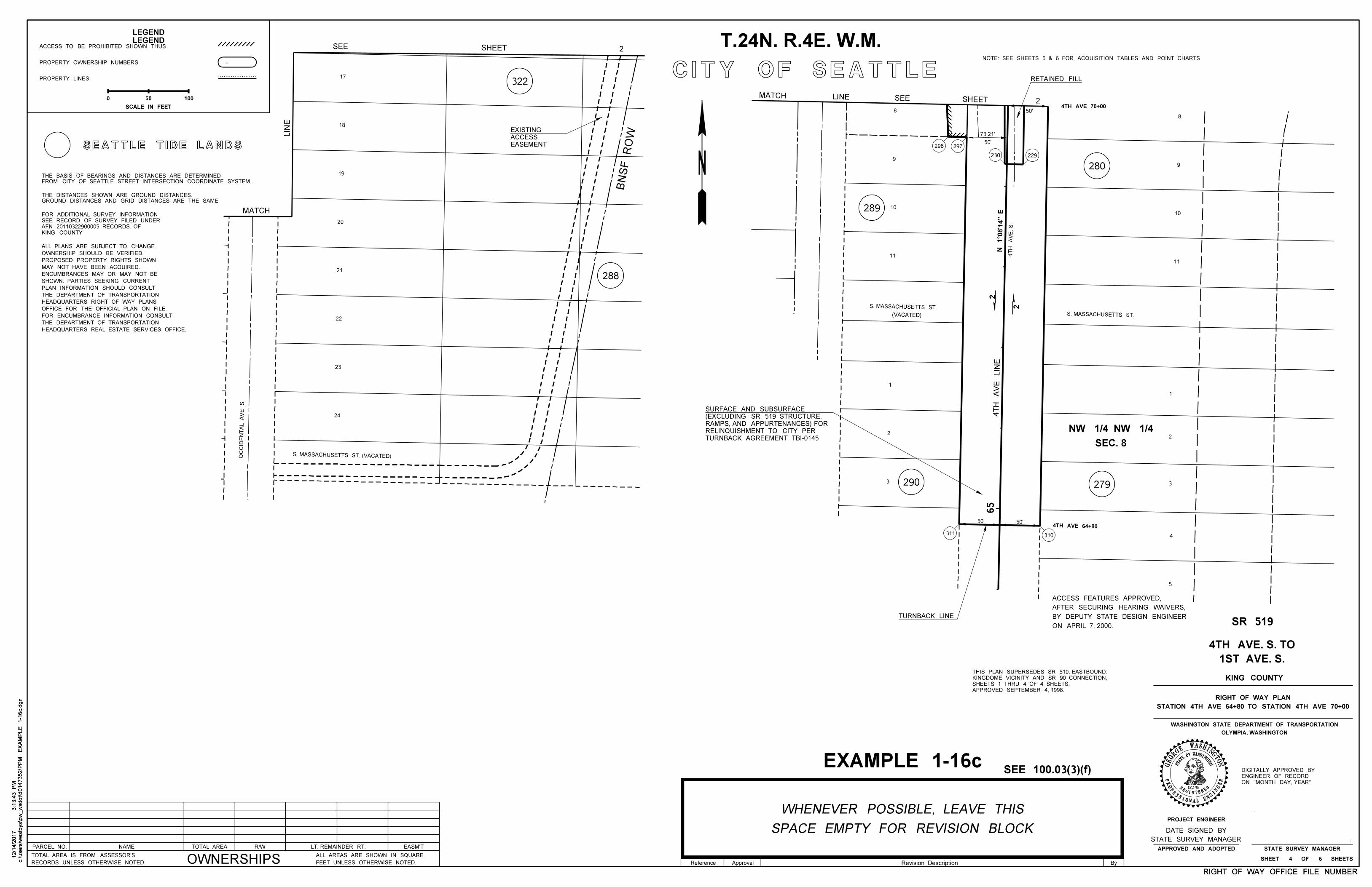
CITY OF SEATTLE
LEGEND
50'
73.21'
50'
PARCEL NO. NAME R/WTOTAL AREA LT. REMAINDER RT. EASM'T
OWNERSHIPSRECORDS UNLESS OTHERWISE NOTED.
TOTAL AREA IS FROM ASSESSOR'S
FEET UNLESS OTHERWISE NOTED.
ALL AREAS ARE SHOWN IN SQUARE
RETAINED FILL
4TH AVE 70+00
50' 50'
TURNBACK LINE
EASEMENT
ACCESS
EXISTING
322
288
S. MASSACHUSETTS ST. (VACATED)
24
23
22
21
20
19
18
17
OC
CID
EN
TA
L
AV
E
S.
290 279
280
289
1
2
3
4
5
S. MASSACHUSETTS ST.
8
9
10
11
(VACATED)
S. MASSACHUSETTS ST.
11 4T
H
AV
E. S.
311 310
229230
297298
8
9
10
4TH AVE 64+80
65
1
2
3
4T
H
AV
E
LIN
E
ON APRIL 7, 2000.
BY DEPUTY STATE DESIGN ENGINEER
AFTER SECURING HEARING WAIVERS,
ACCESS FEATURES APPROVED,
SEE 100.03(3)(f)
LEGEND
ACCESS TO BE PROHIBITED SHOWN THUS
PROPERTY OWNERSHIP NUMBERS
PROPERTY LINES
-
50 100
SCALE IN FEET
0
RIGHT OF WAY OFFICE FILE NUMBERRIGHT OF WAY OFFICE FILE NUMBER
ON "MONTH DAY, YEAR"
ENGINEER OF RECORD
DIGITALLY APPROVED BY
N 1°0
8'1
4" E
EXAMPLE 1-16c
12345
W
STAT
EOFWASHINGTON
REGISTERED
PROFESSIONAL ENGI
NEER
ASHINGTNOGE
OR
GE
SEATTLE TIDE LANDS
GROUND DISTANCES AND GRID DISTANCES ARE THE SAME.
THE DISTANCES SHOWN ARE GROUND DISTANCES.
FROM CITY OF SEATTLE STREET INTERSECTION COORDINATE SYSTEM.
THE BASIS OF BEARINGS AND DISTANCES ARE DETERMINED
KING COUNTY
AFN 20110322900005, RECORDS OF
SEE RECORD OF SURVEY FILED UNDER
FOR ADDITIONAL SURVEY INFORMATION
T.24N. R.4E. W.M.
BN
SF
RO
W
2
2
SEC. 8
NW 1/4 NW 1/4
c:\users\w
estb
ys\p
w_
wsdot\d0147352\P
PM
EX
AM
PLE 1-1
6c.d
gn
3:1
3:4
3 P
M12/1
4/2
017
c:\users\w
estb
ys\p
w_
wsdot\d0147352\P
PM
EX
AM
PLE 1-1
6c.d
gn
3:1
3:4
3 P
M12/1
4/2
017
MATCH
LIN
E
2SHEET SEE LINEMATCH
TURNBACK AGREEMENT TBI-0145
RELINQUISHMENT TO CITY PER
RAMPS, AND APPURTENANCES) FOR
(EXCLUDING SR 519 STRUCTURE,
SURFACE AND SUBSURFACE
SEE SHEET 2
NOTE: SEE SHEETS 5 & 6 FOR ACQUISITION TABLES AND POINT CHARTS
HEADQUARTERS REAL ESTATE SERVICES OFFICE.
THE DEPARTMENT OF TRANSPORTATION
FOR ENCUMBRANCE INFORMATION CONSULT
OFFICE FOR THE OFFICIAL PLAN ON FILE.
HEADQUARTERS RIGHT OF WAY PLANS
THE DEPARTMENT OF TRANSPORTATION
PLAN INFORMATION SHOULD CONSULT
SHOWN. PARTIES SEEKING CURRENT
ENCUMBRANCES MAY OR MAY NOT BE
MAY NOT HAVE BEEN ACQUIRED.
PROPOSED PROPERTY RIGHTS SHOWN
OWNERSHIP SHOULD BE VERIFIED.
ALL PLANS ARE SUBJECT TO CHANGE.
STATE SURVEY MANAGER
SHEET 4 OF 6 SHEETS
PROJECT ENGINEER
APPROVED AND ADOPTED
OLYMPIA, WASHINGTON
WASHINGTON STATE DEPARTMENT OF TRANSPORTATION
KING COUNTY
STATION 4TH AVE 64+80 TO STATION 4TH AVE 70+00
RIGHT OF WAY PLAN
SR 519
1ST AVE. S.
4TH AVE. S. TO
Revision Description ByReference Approval
SPACE EMPTY FOR REVISION BLOCK
WHENEVER POSSIBLE, LEAVE THIS
STATE SURVEY MANAGER
DATE SIGNED BY
APPROVED SEPTEMBER 4, 1998.
SHEETS 1 THRU 4 OF 4 SHEETS,
KINGDOME VICINITY AND SR 90 CONNECTION,
THIS PLAN SUPERSEDES SR 519, EASTBOUND:
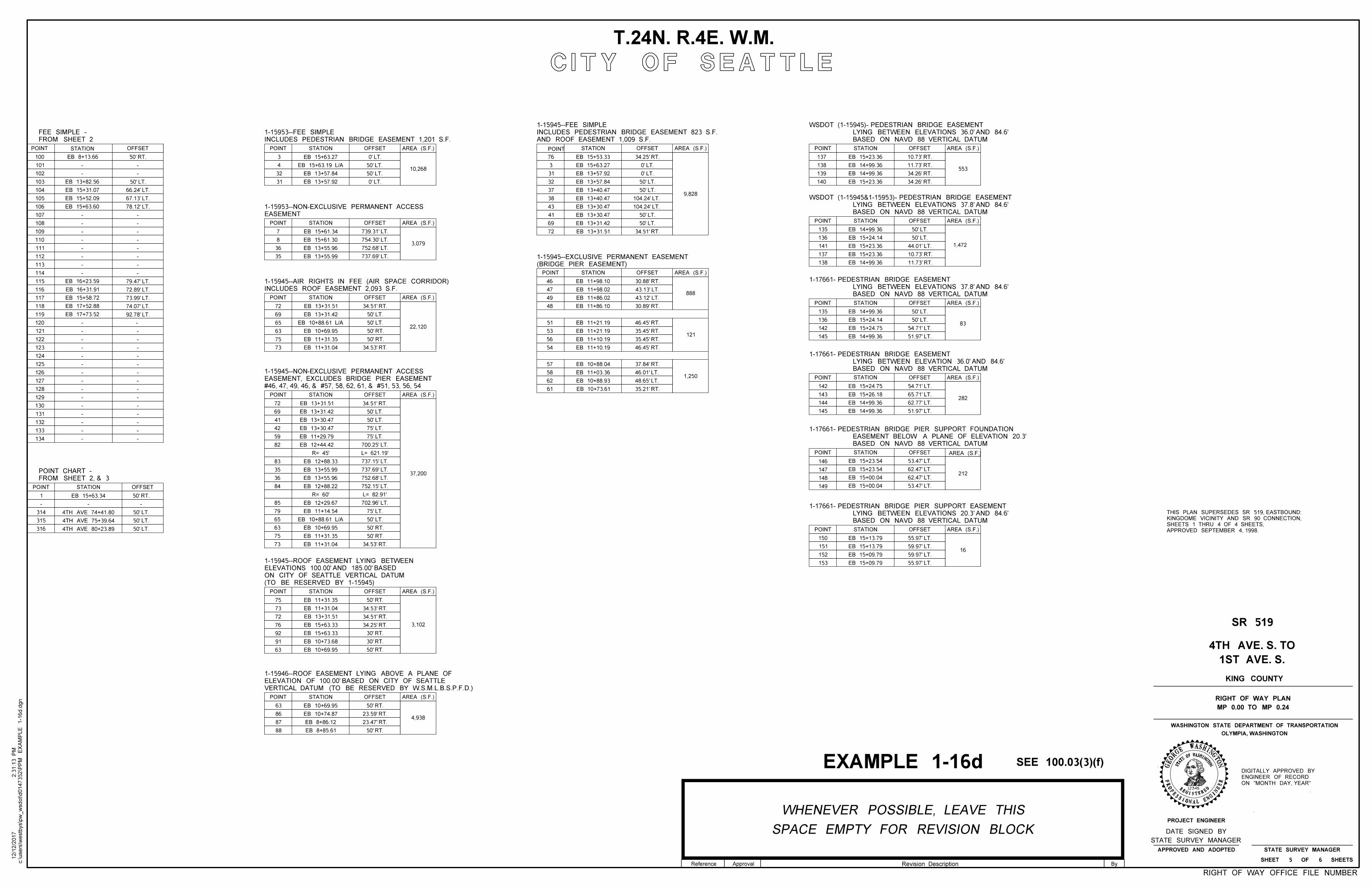
CITY OF SEATTLE
SEE 100.03(3)(f)
RIGHT OF WAY OFFICE FILE NUMBER
T.24N. R.4E. W.M.
EXAMPLE 1-16dON "MONTH DAY, YEAR"
ENGINEER OF RECORD
DIGITALLY APPROVED BY
c:\users\w
estb
ys\p
w_
wsdot\d0147352\P
PM
EX
AM
PLE 1-1
6d.d
gn
2:3
1:1
3 P
M12/1
2/2
017 SPACE EMPTY FOR REVISION BLOCK
WHENEVER POSSIBLE, LEAVE THIS
12345
W
STAT
EOFWASHINGTON
REGISTERED
PROFESSIONAL ENGI
NEER
ASHINGTNOGE
OR
GE
STATE SURVEY MANAGER
DATE SIGNED BY
Revision Description ByReference Approval
PROJECT ENGINEER
STATE SURVEY MANAGERAPPROVED AND ADOPTED
SHEET 5 OF 6 SHEETS
OLYMPIA, WASHINGTON
WASHINGTON STATE DEPARTMENT OF TRANSPORTATION
KING COUNTY
1ST AVE. S.
4TH AVE. S. TO
MP 0.00 TO MP 0.24
RIGHT OF WAY PLAN
SR 519
STATION OFFSET
3
4
32
31
EB 15+63.27
EB 13+57.84
EB 13+57.92
10,268
STATION OFFSET
7
8
36
35
EB 15+61.34
EB 13+55.96
EB 13+55.99
3,079EB 15+61.30
739.31' LT.
754.30' LT.
752.68' LT.
737.69' LT.
STATION OFFSET
72
69
65
63
EB 13+31.51
EB 10+69.9522,120
EB 13+31.42
75
73
EB 11+31.35
EB 11+31.04
STATION OFFSET
72
69
41
42
EB 13+31.51
EB 13+30.47
EB 13+30.47
37,200
EB 13+31.42
59
82
EB 11+29.79
EB 12+44.42 700.25' LT.
34.51' RT.
34.53' RT.
83
35
36
84
85
79
65
63
75
73
EB 12+29.67
EB 10+69.95
EB 11+14.54
EB 11+31.35
EB 11+31.04
EB 12+88.33
EB 13+55.99
EB 13+55.96
EB 12+88.22
34.53' RT.
34.51' RT.
737.15' LT.
737.69' LT.
752.68' LT.
752.15' LT.
702.96' LT.
L= 621.19'
STATION OFFSET
75
73
72
76
EB 11+31.35
EB 15+63.33 3,102
EB 11+31.04
92
91
EB 15+63.33
EB 10+73.68
34.53' RT.
34.51' RT.
34.25' RT.
63 EB 10+69.95
EB 13+31.51
23.59' RT.
23.47' RT.
STATION OFFSET
63
86
87
88
EB 10+69.95
4,938EB 10+74.87
EB 8+86.12
EB 8+85.61
66.24' LT.
67.13' LT.
OFFSET
EB 15+31.07
EB 15+52.09
EB 13+82.56
78.12' LT.EB 15+63.60
79.47' LT.
72.89' LT.
73.99' LT.
EB 16+31.91
EB 15+58.72
EB 16+23.59
74.07' LT.EB 17+52.88
92.78' LT.EB 17+73.52
100
103
104
105
106
115
116
117
118
119
EB 8+13.66
STATION OFFSET
3
31
32
EB 15+53.33
EB 13+57.84
9,828
EB 15+63.27
37
38
EB 13+40.47
EB 13+40.47
34.25' RT.
72 EB 13+31.51 34.51' RT.
69 EB 13+31.42
43 EB 13+30.47
41 EB 13+30.47
76
EB 13+57.92
104.24' LT.
104.24' LT.
STATION OFFSET
46
47
49
48
EB 11+98.10
EB 11+86.02
EB 11+86.10
EB 11+98.02
51
53
56
54
EB 11+21.19
EB 11+10.19
EB 11+10.19
EB 11+21.19
57
58
62
61
EB 10+88.04
EB 10+88.93
EB 10+73.61
EB 11+03.361,250
888
121
30.88' RT.
43.13' LT.
43.12' LT.
30.89' RT.
46.45' RT.
35.45' RT.
35.45' RT.
46.45' RT.
37.84' RT.
46.01' LT.
48.65' LT.
35.21' RT.
101
102
107
108
109
110
111
112
113
114
- -
- -
- -
- -
- -
- -
- -
- -
- -
- -
120
121
122
123
124
125
126
127
128
129
130
131
132
133
134
- -
- -
- -
- -
- -
- -
- -
- -
- -
- -
- -
- -
- -
- -
- -
STATION OFFSET
- -
1
-
EB 15+63.34
314
315
316
4TH AVE 75+39.64
4TH AVE 74+41.80
4TH AVE 80+23.89
50' RT.
50' LT.
50' RT.
50' LT.
50' LT.
50' LT.
0' LT.
50' LT.
50' LT.
0' LT.
50' LT.
50' LT.
50' RT.
50' RT.
50' LT.
50' LT.
75' LT.
75' LT.
75' LT.
50' LT.
50' RT.
50' RT.
30' RT.
50' RT.
30' RT.
50' RT.
50' RT.
50' RT.
0' LT.
0' LT.
50' LT.
50' LT.
50' LT.
50' LT.
146 EB 15+23.54
147 EB 15+23.54
148 EB 15+00.04
149 EB 15+00.04
150 EB 15+13.79
151 EB 15+13.79
152 EB 15+09.79
153 EB 15+09.79
212
16
142 EB 15+24.75
143 EB 15+26.18
144 EB 14+99.36
145 EB 14+99.36
135 EB 14+99.36
136 EB 15+24.14
142 EB 15+24.75
145 EB 14+99.36
282
83
135 EB 14+99.36
136 EB 15+24.14
141 EB 15+23.36
137 EB 15+23.36
138 EB 14+99.36
1,472
137 EB 15+23.36
138 EB 14+99.36
139 EB 14+99.36
140 EB 15+23.36
553
10.73' RT.
11.73' RT.
34.26' RT.
34.26' RT.
STATION OFFSET
STATION OFFSET
STATION OFFSET
STATION OFFSET
STATION OFFSET
STATION OFFSET
44.01' LT.
10.73' RT.
11.73' RT.
54.71' LT.
51.97' LT.
54.71' LT.
65.71' LT.
62.77' LT.
51.97' LT.
53.47' LT.
62.47' LT.
62.47' LT.
53.47' LT.
55.97' LT.
59.97' LT.
59.97' LT.
55.97' LT.
50' LT.
50' LT.
50' LT.
50' LT.
EASEMENT
1-15953--NON-EXCLUSIVE PERMANENT ACCESS
VERTICAL DATUM (TO BE RESERVED BY W.S.M.L.B.S.P.F.D.)
ELEVATION OF 100.00' BASED ON CITY OF SEATTLE
1-15946--ROOF EASEMENT LYING ABOVE A PLANE OF
(TO BE RESERVED BY 1-15945)
ON CITY OF SEATTLE VERTICAL DATUM
ELEVATIONS 100.00' AND 185.00' BASED
1-15945--ROOF EASEMENT LYING BETWEEN
FROM SHEET 2
FEE SIMPLE -
FROM SHEET 2, & 3
POINT CHART -
BASED ON NAVD 88 VERTICAL DATUM
EASEMENT BELOW A PLANE OF ELEVATION 20.3'
1-17661- PEDESTRIAN BRIDGE PIER SUPPORT FOUNDATION
BASED ON NAVD 88 VERTICAL DATUM
LYING BETWEEN ELEVATIONS 20.3' AND 84.6'
1-17661- PEDESTRIAN BRIDGE PIER SUPPORT EASEMENT
BASED ON NAVD 88 VERTICAL DATUM
LYING BETWEEN ELEVATIONS 37.8' AND 84.6'
1-17661- PEDESTRIAN BRIDGE EASEMENT
(BRIDGE PIER EASEMENT)
1-15945--EXCLUSIVE PERMANENT EASEMENT
POINT
POINT
POINT
POINT
POINT
POINT STATION POINT
POINT
POINT
POINT
POINT
POINT
POINT
POINT
POINT
POINT
EB 15+63.19 L/A
AREA (S.F.)
INCLUDES PEDESTRIAN BRIDGE EASEMENT 1,201 S.F.
1-15953--FEE SIMPLE
INCLUDES ROOF EASEMENT 2,093 S.F.
1-15945--AIR RIGHTS IN FEE (AIR SPACE CORRIDOR)
AREA (S.F.)
AREA (S.F.)
AREA (S.F.)
AREA (S.F.)
AREA (S.F.)
AREA (S.F.)
AREA (S.F.)
AREA (S.F.)
AREA (S.F.)
AREA (S.F.)
AREA (S.F.)
AREA (S.F.)
EB 10+88.61 L/A
R= 45'
L= 82.91'R= 60'
EB 10+88.61 L/A
#46, 47, 49, 46, & #57, 58, 62, 61, & #51, 53, 56, 54
EASEMENT, EXCLUDES BRIDGE PIER EASEMENT
1-15945--NON-EXCLUSIVE PERMANENT ACCESS
AREA (S.F.)
AND ROOF EASEMENT 1,009 S.F.
INCLUDES PEDESTRIAN BRIDGE EASEMENT 823 S.F.
1-15945--FEE SIMPLE
BASED ON NAVD 88 VERTICAL DATUM
LYING BETWEEN ELEVATIONS 36.0' AND 84.6'
WSDOT (1-15945)- PEDESTRIAN BRIDGE EASEMENT
BASED ON NAVD 88 VERTICAL DATUM
LYING BETWEEN ELEVATIONS 37.8' AND 84.6'
WSDOT (1-15945&1-15953)- PEDESTRIAN BRIDGE EASEMENT
BASED ON NAVD 88 VERTICAL DATUM
LYING BETWEEN ELEVATION 36.0' AND 84.6'
1-17661- PEDESTRIAN BRIDGE EASEMENT
APPROVED SEPTEMBER 4, 1998.
SHEETS 1 THRU 4 OF 4 SHEETS,
KINGDOME VICINITY AND SR 90 CONNECTION,
THIS PLAN SUPERSEDES SR 519, EASTBOUND:
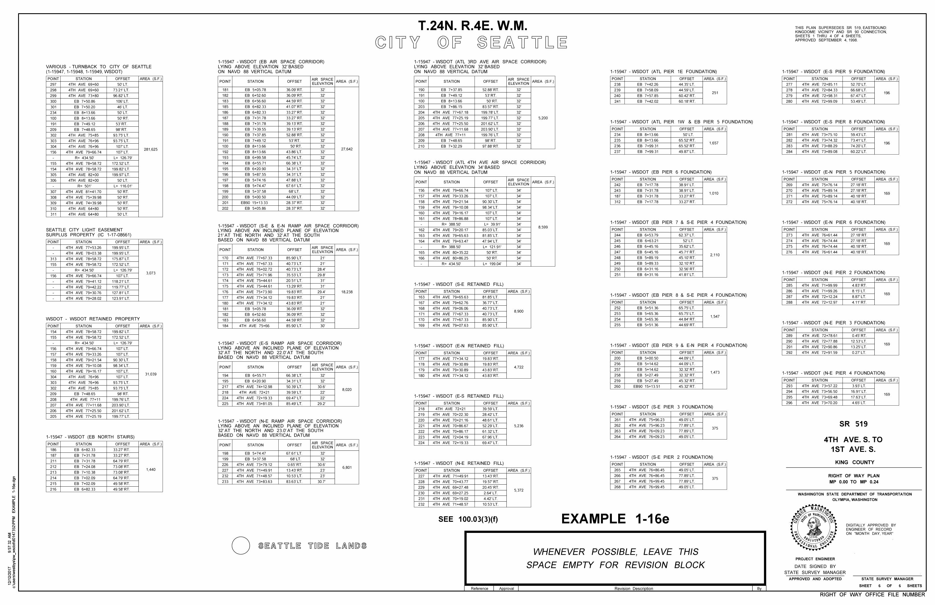
CITY OF SEATTLE
SEE 100.03(3)(f)
RIGHT OF WAY OFFICE FILE NUMBERRIGHT OF WAY OFFICE FILE NUMBER
T.24N. R.4E. W.M.
EXAMPLE 1-16eON "MONTH DAY, YEAR"
ENGINEER OF RECORD
DIGITALLY APPROVED BY
c:\users\w
estb
ys\p
w_
wsdot\d0147352\P
PM
EX
AM
PLE 1-1
6e.d
gn
9:5
7:3
2
AM
12/1
2/2
017
c:\users\w
estb
ys\p
w_
wsdot\d0147352\P
PM
EX
AM
PLE 1-1
6e.d
gn
9:5
7:3
2
AM
12/1
2/2
017
SEATTLE TIDE LANDS
SPACE EMPTY FOR REVISION BLOCK
WHENEVER POSSIBLE, LEAVE THIS
12345
W
STAT
EOFWASHINGTON
REGISTERED
PROFESSIONAL ENGI
NEER
ASHINGTNOGE
OR
GE
STATE SURVEY MANAGER
DATE SIGNED BY
Revision Description ByReference Approval
APPROVED SEPTEMBER 4, 1998.
SHEETS 1 THRU 4 OF 4 SHEETS,
KINGDOME VICINITY AND SR 90 CONNECTION,
THIS PLAN SUPERSEDES SR 519, EASTBOUND:
R= 434.50' L= 126.79'
L= 116.01'
4TH AVE 69+60
4TH AVE 69+60
4TH AVE 73+80
4TH AVE 75+85
4TH AVE 76+96
4TH AVE 76+96
4TH AVE 78+58.72
4TH AVE 82+00
4TH AVE 82+00
4TH AVE 81+41.70
4TH AVE 64+80
4TH AVE 64+80
R= 434.50'
4TH AVE 79+41.12
L= 126.79'
4TH AVE 79+30.76
R= 434.50' L= 126.79'
4TH AVE 76+96
4TH AVE 76+96
EB 7+48.65
4TH AVE 75+85
53' RT.
4TH AVE 75+66
STATION OFFSET
280
277
278
279
52.70' LT.
66.68' LT.196
284
281
282
283
59.43' LT.
73.41' LT.196
67.47' LT.
53.49' LT.
74.20' LT.
60.22' LT.
4TH AVE 72+85.11
4TH AVE 72+84.33
4TH AVE 72+98.31
4TH AVE 72+99.09
4TH AVE 73+75.10
4TH AVE 73+74.32
4TH AVE 73+88.29
4TH AVE 73+89.08
272
269
270
271
27.18' RT.
27.18' RT.
40.18' RT.
40.18' RT.
169
4TH AVE 75+76.14
4TH AVE 75+89.14
4TH AVE 75+89.14
4TH AVE 75+76.14
276
273
274
275169
4TH AVE 76+61.44
4TH AVE 76+74.44
4TH AVE 76+74.44
4TH AVE 76+61.44
27.18' RT.
27.18' RT.
40.18' RT.
40.18' RT.
288
285
286
287169
4TH AVE 71+99.99
4TH AVE 71+99.26
4TH AVE 72+12.24
4TH AVE 72+12.97
4.83' RT.
8.15' LT.
8.87' LT.
4.11' RT.
292
289
290
291169
4TH AVE 72+78.61
4TH AVE 72+77.88
4TH AVE 72+90.86
4TH AVE 72+91.59
0.45' RT.
12.53' LT.
13.25' LT.
0.27' LT.
296
293
294
295169
4TH AVE 73+57.22
4TH AVE 73+56.50
4TH AVE 73+69.48
4TH AVE 73+70.20
3.93' LT.
16.91' LT.
17.63' LT.
4.65' LT.
36.09' RT.
36.09' RT.
44.59' RT.
41.07' RT.
27,642
181
182
183
185
186
187
188
189
190
191
100
192
193
194
195
196
197
198
199
200
201
202
85.90' LT.
40.73' LT.
40.73' LT.
35.53' LT.
18,238
170
171
172
173
174
175
176
177
180
181
182
183
184
66.38' LT.
34.31' LT.
50.39' LT.
39.59' LT.8,020
194
195
217
218
224
225
67.61' LT.
0.65' RT.
13.43' RT.6,801
198
199
226
227
232
233
10.53' LT.
83.63' LT.
4TH AVE 73+79.12
EB 5+74.47
EB 5+37.58
4TH AVE 71+49.91
4TH AVE 71+48.57
4TH AVE 73+83.63
EB 6+55.71
EB 6+20.90
69.47' LT.
85.49' LT.
4TH AVE 74+12.98
4TH AVE 72+19.33
4TH AVE 73+81.05
4TH AVE 77+67.33
4TH AVE 77+67.33
4TH AVE 76+02.72
4TH AVE 75+71.96
4TH AVE 75+44.61
4TH AVE 75+44.61
4TH AVE 75+73.90
4TH AVE 77+34.12
4TH AVE 77+34.12
20.51' LT.
13.29' RT.
85.90' LT.
19.83' RT.
19.83' RT.
43.83' RT.
36.09' RT.
36.09' RT.
44.59' RT.
EB 5+05.78
EB 6+52.60
EB 6+56.60
EB 5+05.78
EB 6+52.60
EB 6+56.60
EB 6+82.33
33.27' RT.EB 6+82.33
33.27' RT.EB 7+31.78
39.13' RT.EB 7+31.78
39.13' RT.EB 7+39.55
52.88' RT.EB 7+37.85
EB 7+49.12
EB 8+13.66
43.86' LT.EB 8+13.66
45.74' LT.EB 6+99.58
66.38' LT.EB 6+55.71
34.31' LT.EB 6+20.90
34.31' LT.EB 5+87.55
47.88' LT.EB 5+74.16
67.61' LT.EB 5+74.47
EB 5+37.58
44.09' LT.EB 5+00.50
28.37' RT.
28.37' RT.EB 5+05.86
EB90 15+13.33
5,200
208
209 EB 7+48.65
190
191
100
52.88' RT.EB 7+37.85
EB 7+49.12
EB 8+13.66
83.57' RT.203
204
205
206
207
210 97.88' RT.EB 7+32.29
EB 7+86.15
4TH AVE 77+67.18
4TH AVE 77+25.19
4TH AVE 77+25.50
4TH AVE 77+11.68
8,599
163
164
81.85' LT.
47.94' LT.
156
157
158 90.30' LT.
98.34' LT.
85.03' LT.
159
160
161
162
4TH AVE 79+16.17
4TH AVE 78+86.88
4TH AVE 79+20.17
4TH AVE 79+65.63
4TH AVE 79+66.74
4TH AVE 79+33.26
4TH AVE 79+21.54
4TH AVE 79+10.08
4TH AVE 79+63.47
4TH AVE 80+35.22
4TH AVE 80+86.25
R= 388.50'
R= 388.50'
R= 434.50'
L= 121.91'
L= 199.04'
165
166
199.78' LT.
199.77' LT.
201.62' LT.
203.90' LT.
199.76' LT.
73.21' LT.
96.82' LT.
297
298
299
300
301
234
100
191
209
302
303
304
156
155
154
305
306
307
308
309
EB 7+50.86
EB 7+50.20
EB 8+13.66
EB 8+13.66
EB 7+49.12
EB 7+48.65
93.75' LT.
93.75' LT.
281,625
310
311
4TH AVE 79+66.74
172.52' LT.
199.82' LT.
199.97' LT.
4TH AVE 75+39.98
4TH AVE 74+39.98
4TH AVE 78+58.72
313
155
156
4TH AVE 77+53.26
4TH AVE 78+03.38
4TH AVE 78+58.72
4TH AVE 79+28.02
172.52' LT.
-
3,073
4TH AVE 78+58.72
4TH AVE 79+66.74
4TH AVE 79+42.22
199.95' LT.
199.95' LT.
175.87' LT.
118.21' LT.
119.77' LT.
127.81' LT.
123.91' LT.
156
158
4TH AVE 78+58.72
4TH AVE 78+58.72
31,039
4TH AVE 79+66.74
4TH AVE 79+21.54
4TH AVE 79+10.08
4TH AVE 79+16.17
199.82' LT.
172.52' LT.
154
155
157 4TH AVE 79+33.26
159
160
304
303
302
209
199.76' LT.208
4TH AVE 77+11.68 203.90' LT.207
4TH AVE 77+25.50 201.62' LT.206
4TH AVE 77+25.19 199.77' LT.205
90.30' LT.
98.34' LT.
93.75' LT.
93.75' LT.
212
214
1,440
186
187
213
215
216
211
EB 6+82.33
EB 7+31.78
EB 7+31.78
EB 7+24.08
EB 7+10.38
EB 7+02.09
EB 7+02.09
EB 6+82.33
33.27' RT.
33.27' RT.
64.79' RT.
73.08' RT.
73.08' RT.
64.79' RT.
49.58' RT.
49.58' RT.
171
169
8,900
163
167
170
168
81.85' LT.
36.77' LT.
40.73' LT.
40.73' LT.
85.90' LT.
85.90' LT.
4TH AVE 79+65.63
4TH AVE 79+62.76
4TH AVE 79+06.06
4TH AVE 77+67.33
4TH AVE 77+67.33
4TH AVE 79+07.63
180
4,722
177
178
179
19.83' RT.
19.83' RT.
43.83' RT.
43.83' RT.
4TH AVE 77+34.12
4TH AVE 79+30.89
4TH AVE 79+30.89
4TH AVE 77+34.12
221
223
5,236
218
219
222
220
39.59' LT.
28.42' LT.
48.61' LT.
52.29' LT.
61.32' LT.
67.96' LT.
4TH AVE 70+22.30
4TH AVE 70+21.16
4TH AVE 70+86.67
4TH AVE 70+86.17
4TH AVE 72+04.19
224 69.47' LT.4TH AVE 72+19.33
2305,372
227
228
231
229
13.43' RT.
19.57' RT.
20.45' RT.
2.64' LT.
4.42' LT.
4TH AVE 71+49.91
4TH AVE 70+43.77
4TH AVE 69+27.48
4TH AVE 69+27.25
4TH AVE 70+19.02
241
238
239
240
44.35' LT.
44.59' LT.
60.42' RT.
60.18' RT.
251
EB 7+42.26
EB 7+58.09
EB 7+57.85
EB 7+42.02
237
234
235
236
65.52' RT.
65.52' RT.
49.87' LT.
EB 8+13.66
EB 8+13.66
EB 7+99.31
EB 7+99.31
1,657
312
242
243
187
38.91' LT.
38.91' LT.
33.27' RT.
33.27' RT.
EB 7+17.78
EB 7+31.78
EB 7+31.78
EB 7+17.78
1,010
247
244
245
246
62.37' LT.
35.62' LT.
45.71' RT.
EB 6+53.79
EB 6+63.21
EB 6+45.16
EB 6+45.16
248 45.10' RT.EB 5+89.19
249 32.10' RT.EB 5+89.33
250 32.56' RT.EB 6+31.16
251 41.81' LT.EB 6+31.16
2,110
255
252
253
254
65.75' LT.
65.75' LT.
44.84' RT.
44.69' RT.
EB 5+51.36
EB 5+65.36
EB 5+65.36
EB 5+51.36
1,547
258
200
256
257
44.09' LT.
44.09' LT.
32.32' RT.
32.32' RT.
EB 5+00.50
EB 5+14.62
EB 5+14.62
EB 5+27.491,473
260
259 45.32' RT.EB 5+27.49
45.32' RT.EB90 15+13.51
264
261
262
263
49.05' LT.
77.89' LT.
77.89' LT.
49.05' LT.
375
268
265
266
267
49.05' LT.
77.89' LT.
77.89' LT.
49.05' LT.
375
4TH AVE 75+96.23
4TH AVE 75+96.23
4TH AVE 76+09.23
4TH AVE 76+09.23
4TH AVE 76+86.45
4TH AVE 76+86.45
4TH AVE 76+99.45
4TH AVE 76+99.45
28.4'
29.8'
29.4'
30.6'
29.2'
30.6'
30.7'
50' LT.
50' LT.
50' LT.
50' LT.
50' LT.
50' RT.
50' RT.
50' RT.
50' RT.
50' RT.
50' RT.
50' RT.
50' RT.
50' RT.
32'
32'
32'
32'
32'
32'
32'
32'
32'
32'
32'
32'
32'
32'
32'
32'
32'
32'
32'
32'
32'
32'
32'
32'
32'
32'
32'
32'
32'
32'
32'
32'
32'
32'
32'
32'
32'
32'
32'
32'
30'
34'
34'
34'
34'
34'
34'
34'
34'
34'
34'
34'
34'
34'
34'
107' LT.
107' LT.
107' LT.
107' LT.
107' LT.
107' LT.
107' LT.
107' LT.
107' LT.
107' LT.
107' LT.
68' LT.
23'
23'
98' RT.
106' LT.
46' LT.
4TH AVE 77+11
22'
22'
21'
21'
21'
21'
31'
31'
52' LT.
232 10.53' LT.4TH AVE 71+48.57
ON NAVD 88 VERTICAL DATUM
LYING ABOVE ELEVATION 32' BASED
1-15947 - WSDOT (ATL 3RD AVE AIR SPACE CORRIDOR)
ON NAVD 88 VERTICAL DATUM
LYING ABOVE ELEVATION 34' BASED
1-15947 - WSDOT (ATL 4TH AVE AIR SPACE CORRIDOR)
SURPLUS PROPERTY (IC 1-17-08661)
SEATTLE CITY LIGHT EASEMENT
OFFSETSTATION
OFFSETSTATION
OFFSETSTATION
OFFSETSTATION
OFFSETSTATION
OFFSETSTATION
1-15947 - WSDOT (E-S PIER 9 FOUNDATION)
1-15947 - WSDOT (E-S PIER 8 FOUNDATION)
1-15947 - WSDOT (E-N PIER 5 FOUNDATION)
1-15947 - WSDOT (E-N PIER 6 FOUNDATION)
1-15947 - WSDOT (N-E PIER 2 FOUNDATION)
1-15947 - WSDOT (N-E PIER 3 FOUNDATION)
1-15947 - WSDOT (N-E PIER 4 FOUNDATION)
STATION OFFSET
STATION OFFSET
STATION OFFSET
STATION OFFSET
STATION OFFSET
STATION OFFSET
STATION OFFSET
STATION OFFSET
STATION OFFSET
STATION OFFSET
STATION OFFSET
STATION OFFSET
STATION OFFSET
OFFSETSTATION
OFFSETSTATION
OFFSETSTATION
OFFSETSTATION
ELEVATION
AIR SPACEPOINT AREA (S.F.)
AREA (S.F.)
AREA (S.F.)
AREA (S.F.)
AREA (S.F.)
AREA (S.F.)
AREA (S.F.)
AREA (S.F.)
AREA (S.F.)
AREA (S.F.)
AREA (S.F.)
AREA (S.F.)
AREA (S.F.)
AREA (S.F.)
AREA (S.F.)
AREA (S.F.)
AREA (S.F.)
AREA (S.F.)
AREA (S.F.)
AREA (S.F.)
AREA (S.F.)
AREA (S.F.)
AREA (S.F.)
AREA (S.F.)
POINT
POINT
POINT
POINT
POINT
POINT
POINT
POINT
POINT
POINT
POINT
POINT
POINT
POINT
POINT
POINT
POINT
POINT
POINT
POINT
POINT
POINT
POINT
POINT STATION OFFSET AREA (S.F.)ELEVATION
AIR SPACE
POINT STATION OFFSET AREA (S.F.)ELEVATION
AIR SPACE
POINT STATION OFFSET AREA (S.F.)ELEVATION
AIR SPACE
POINT STATION OFFSET AREA (S.F.)ELEVATION
AIR SPACE
POINT STATION OFFSET AREA (S.F.)ELEVATION
AIR SPACE
1-15947 - WSDOT (ATL PIER 1E FOUNDATION)
1-15947 - WSDOT (EB PIER 6 FOUNDATION)
1-15947 - WSDOT (ATL PIER 1W & EB PIER 5 FOUNDATION)
1-15947 - WSDOT (EB PIER 8 & S-E PIER 4 FOUNDATION)
1-15947 - WSDOT (EB PIER 9 & E-N PIER 4 FOUNDATION)
1-15947 - WSDOT (S-E RETAINED FILL)
1-15947 - WSDOT (E-N RETAINED FILL)
1-15947 - WSDOT (E-S RETAINED FILL)
1-15947 - WSDOT (N-E RETAINED FILL)
1-15947 - WSDOT (S-E PIER 3 FOUNDATION)
1-15947 - WSDOT (S-E PIER 2 FOUNDATION)
1-15947 - WSDOT (EB PIER 7 & S-E PIER 4 FOUNDATION)
ON NAVD 88 VERTICAL DATUM
LYING ABOVE ELEVATION 32' BASED
1-15947 - WSDOT (EB AIR SPACE CORRIDOR)
BASED ON NAVD 88 VERTICAL DATUM
21' AT THE NORTH AND 32' AT THE SOUTH
LYING ABOVE AN INCLINED PLANE OF ELEVATION
1-15947 - WSDOT (S-E & E-N RAMP AIR SPACE CORRIDOR)
BASED ON NAVD 88 VERTICAL DATUM
32' AT THE NORTH AND 22.0' AT THE SOUTH
LYING ABOVE AN INCLINED PLANE OF ELEVATION
1-15947 - WSDOT (E-S RAMP AIR SPACE CORRIDOR)
BASED ON NAVD 88 VERTICAL DATUM
32' AT THE NORTH AND 23.0' AT THE SOUTH
LYING ABOVE AN INCLINED PLANE OF ELEVATION
1-15947 - WSDOT (N-E RAMP AIR SPACE CORRIDOR)
1-15947 - WSDOT (EB NORTH STAIRS)
WSDOT - WSDOT RETAINED PROPERTY
(1-15947, 1-15948, 1-15949, WSDOT)
VARIOUS - TURNBACK TO CITY OF SEATTLE
-
-
-
-
-
-
-
-
-
-
-
-
R= 501'
L= 39.91'
PROJECT ENGINEER
STATE SURVEY MANAGERAPPROVED AND ADOPTED
SHEET 6 OF 6 SHEETS
OLYMPIA, WASHINGTON
WASHINGTON STATE DEPARTMENT OF TRANSPORTATION
KING COUNTY
1ST AVE. S.
4TH AVE. S. TO
MP 0.00 TO MP 0.24
RIGHT OF WAY PLAN
SR 519
4TH AVE 77+11
53' RT.
98' RT.
68' LT.
53' RT.
98' RT.
4TH AVE 72+21
4TH AVE 72+21
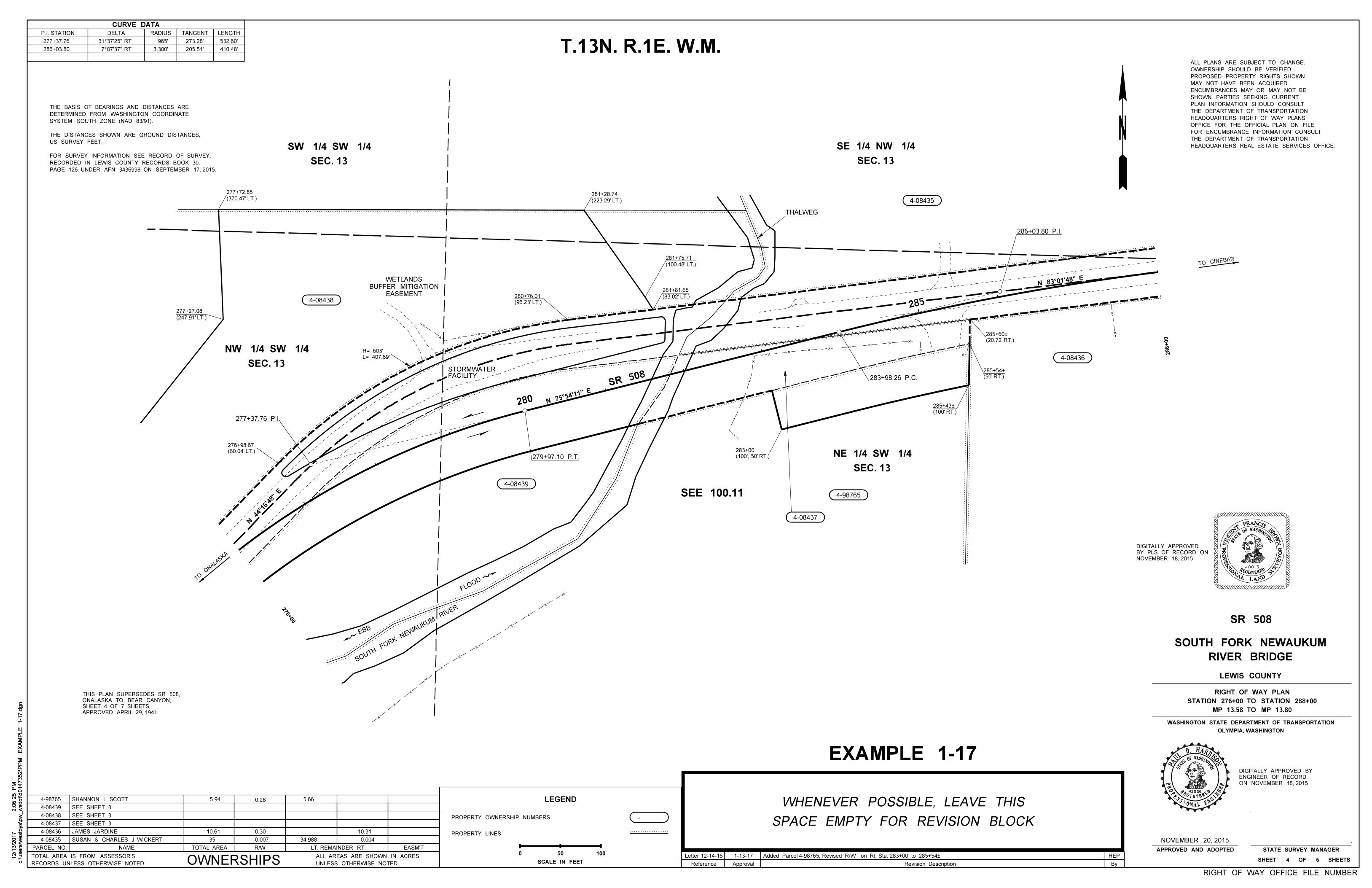
REGISTERED
STAT
EOFWASHINGTON
PR
OFESSIONAL LAND
SURVEY
OR
40013
VIN
CE
NT FRANCIS BROW
N
HEADQUARTERS REAL ESTATE SERVICES OFFICE.
THE DEPARTMENT OF TRANSPORTATION
FOR ENCUMBRANCE INFORMATION CONSULT
OFFICE FOR THE OFFICIAL PLAN ON FILE.
HEADQUARTERS RIGHT OF WAY PLANS
THE DEPARTMENT OF TRANSPORTATION
PLAN INFORMATION SHOULD CONSULT
SHOWN. PARTIES SEEKING CURRENT
ENCUMBRANCES MAY OR MAY NOT BE
MAY NOT HAVE BEEN ACQUIRED.
PROPOSED PROPERTY RIGHTS SHOWN
OWNERSHIP SHOULD BE VERIFIED.
ALL PLANS ARE SUBJECT TO CHANGE.
LEGEND
PROPERTY OWNERSHIP NUMBERS
PROPERTY LINES
SCALE IN FEET
0
-
50 100
T.13N. R.1E. W.M.
288+00
TO
ON
ALA
SKA
TO CINEBAR
STAT
EOFWASHINGTON
REGISTERED
PROFESSIONAL ENGI
NEER
42936
NOSIR
RAH .D LUAP
276+00
APPROVED APRIL 29, 1941.
SHEET 4 OF 7 SHEETS,
ONALASKA TO BEAR CANYON,
THIS PLAN SUPERSEDES SR 508,
CURVE DATA
P.I. STATION DELTA RADIUS TANGENT LENGTH
7°07'37" RT.
31°37'25" RT.
205.51'
273.28' 277+37.76
286+03.80
965'
3,300'
532.60'
410.48'
NOVEMBER 20, 2015
4-08437
280
285
279+97.10 P.T.
283+98.26 P.C.
4-08439
N 75°54'11" E
286+03.80 P.I.
SEC. 13
NE 1/4 SW 1/4
277+37.76 P.I.
FLOOD
EBB
SOUTH FORK
NEWAUKUM
RIVER
(60.04' LT.)
276+98.67
L= 407.69'
R= 603'
FACILITYSTORMWATER
SEC. 13
SE 1/4 NW 1/4
THALWEG
(50' RT.)
285+54À
(20.72' RT.)
285+60À
(96.23' LT.)
280+76.01
SR 508
N 44°16'48"
E
N 83°01'48" E
SEC. 13
SW 1/4 SW 1/4
4-08438
4-08435
4-08436
SUSAN & CHARLES J WICKERT
JAMES JARDINE 10.61
35 0.007
0.30
34.988 0.004
10.31
4-98765
ON NOVEMBER 18, 2015
ENGINEER OF RECORD
DIGITALLY APPROVED BY
NOVEMBER 18, 2015
BY PLS OF RECORD ON
DIGITALLY APPROVED
c:\users\w
estb
ys\p
w_
wsdot\d0147352\P
PM
EX
AM
PLE 1-1
7.d
gn
2:0
6:2
5 P
M12/1
3/2
017
c:\users\w
estb
ys\p
w_
wsdot\d0147352\P
PM
EX
AM
PLE 1-1
7.d
gn
2:0
6:2
5 P
M12/1
3/2
017
SPACE EMPTY FOR REVISION BLOCK
WHENEVER POSSIBLE, LEAVE THIS
Revision Description ByReference Approval
PAGE 126 UNDER AFN 3436998 ON SEPTEMBER 17, 2015.
RECORDED IN LEWIS COUNTY RECORDS BOOK 30,
FOR SURVEY INFORMATION SEE RECORD OF SURVEY,
US SURVEY FEET.
THE DISTANCES SHOWN ARE GROUND DISTANCES,
SYSTEM SOUTH ZONE (NAD 83/91).
DETERMINED FROM WASHINGTON COORDINATE
THE BASIS OF BEARINGS AND DISTANCES ARE
EXAMPLE 1-17
(100', 50' RT.)
283+00
RIGHT OF WAY OFFICE FILE NUMBER
Added Parcel 4-98765; Revised R/W on Rt. Sta. 283+00 to 285+54ÀLetter 12-14-16 1-13-17 HEP
EASEMENT
BUFFER MITIGATION
WETLANDS
(247.91' LT.)
277+27.08
(370.47' LT.)
277+72.85
(223.29' LT.)
281+28.74
(100.48' LT.)
281+75.71
(83.02' LT.)
281+81.65
SEC. 13
NW 1/4 SW 1/4
4-98765 SHANNON L SCOTT 5.94 0.28 5.66
4-08438
4-08437
4-08436
4-08435
PARCEL NO. NAME R/WTOTAL AREA LT. REMAINDER RT. EASM'T
OWNERSHIPSRECORDS UNLESS OTHERWISE NOTED.
TOTAL AREA IS FROM ASSESSOR'S
UNLESS OTHERWISE NOTED.
ALL AREAS ARE SHOWN IN ACRES
4-08439
SEE SHEET 3
SEE SHEET 3
SEE SHEET 3
SEE 100.11
SR 508
RIVER BRIDGE
SOUTH FORK NEWAUKUM
LEWIS COUNTY
OLYMPIA, WASHINGTON
WASHINGTON STATE DEPARTMENT OF TRANSPORTATION
MP 13.58 TO MP 13.80
STATION 276+00 TO STATION 288+00
RIGHT OF WAY PLAN
SHEET 4 OF 6 SHEETS
STATE SURVEY MANAGERAPPROVED AND ADOPTED
(100' RT.)
285+43À