distribution transformers protection against high ...pe.org.pl/articles/2012/5a/71.pdf ·...
TRANSCRIPT

296 PRZEGLĄD ELEKTROTECHNICZNY (Electrical Review), ISSN 0033-2097, R. 88 NR 5a/2012
Dariusz SMUGAŁA1, Wojciech PIASECKI1, Magdalenia OSTROGORSKA1, Marek FLORKOWSKI1, Marek FULCZYK1, Paweł KŁYS2
ABB Sp.z.o.o., Corporate Research Center, (1), ABB Sp.z.o.o., ABB Distribution Transformers, (2)
Distribution transformers protection against High Frequency Switching Transients
Abstract. Distribution transformers protection method against high frequency transients generated during Vacuum Circuit Breaker (VCB) operations is presented in this paper. ATP/EMTP simulations of transients generated during the VCB operation and protection method effectiveness is described. In addition prototype windmill installation is presented. For simulations realistic VCB model was used enabling one to study both pre-strikes, generated during the contact making process as well as re-ignitions generated during the contact breaking. Streszczenie. W artykule przedstawiono metodę ochrony transformatorów dystrybucyjnych przed wysokoczęstotliwościowymi przepięciami generowanymi podczas operacji łączeniowych z użyciem wyłączników próżniowych. W artykule przedstawiono symulacje komputerowe przepięć generowanych zarówno podczas załączania jak i wyłączania transformatorów. Symulacji dokonano przy użyciu pakietu ATP/EMTP. Zaprezentowano również przykładową istniejącą instalację opisanych w artykule urządzeń. (Ochrona transformatorów dystrybucyjnych przed wysokoczęstotliwościowymi przepięciami łączeniowymi). Keywords: przepięcia łączeniowe, transformatory, ochrona. Słowa kluczowe: switching transients, transformers, protection. Introduction Transformers operating in power network are exposed to various types of surges. High frequency transients and high rate overvoltages pose a hazards to the connected equipment [2] and can create local overstressing of the insulation system. One of the potential sources of high du/dt transients are Vacuum Circuit Breakers (VCB). According to [1], of special concern are: transformers connected to cables of moderate length, transformers connected to GIS, transformers connected through a VCB, dry type transformers connected through the cables, transformers exposed to lightning, transformers exposed to frequent switching operations.
Complex internal structure of the transformer results in multiple internal resonances which may cause non uniform voltage distribution at high frequencies and local resonant amplification of voltage.
The phenomena resulting from the VCB–cable–transformer interaction may generate VFT overvoltages overstressing the insulation system of transformers which can negatively affect the equipment lifetime and may lead to an internal short-circuit. VCB Switching transients – problem description Connecting and disconnecting a transformer using a VCB involving the interaction between the cable and transformer capacitance and transformer inductance is well described in the literature [3÷5,8]. It results in dangerous HF stresses on transformer windings insulation. Cable capacitance combined with the inductive character of the transformer impedance results in oscillatory escalation of the Transient Recovery Voltage (TRV) across the breaker contacts. In consequence the fast TRV built-up during switching-off may lead to multiple re-ignitions (Fig.3÷4). This process depends strongly on the system parameters (mainly on the inductive current value and on the phase-to ground capacitance), e.g for: a. Unloaded small transformer with large L and very low inductive current ( ~0.1A), b. Unloaded large transformer with rather large L and low inductive current (~1A), c. Inductively loaded large transformer with low L and large inductive current (~50A).
Fig.1. Voltage across the transformer terminals for low inductive current value
Fig.2.Voltage across the transformer terminals for large inductive current value
Fig.3. Voltage across the transformer terminals for large inductive current value

PRZEGLĄD ELEKTROTECHNICZNY (Electrical Review), ISSN 0033-2097, R. 88 NR 5a/2012 297
It is clearly seen that for the predefined value of C, the value of the inductive current has a critical importance on the re-ignitions generation process.
The process of generating re-ignitions in the VCB can be briefly described as follows:
During contact breaking, after physical separation of the contacts arc conducts the current until it drops below the chopping current value (typically 2÷5 A). When the current is chopped, the energy is trapped in the oscillatory circuit (L, C) and the voltage at the transformer starts to oscillate. When the TRV across the contacts exceeds the dielectric withstand, arc re-ignites, the C is re-charged and the current is chopped again. The process continues until the contacts separate so that the dielectric withstand exceeds the TRV.
During the contact making of the VCB high du/dt transients may also be generated, especially, when relatively short cables of small surge impedance between the VCB and the transformer exists. This type of a short, low surge impedance connection has a low du/dt limiting effectiveness. Therefore high value of overvoltages and high frequency transients are expected. The process of high du/dt transients generation during the contact making process is briefly summarized below.
When the distance between the contacts becomes small, arc ignites and the internal capacitance of the transformer is charged from the network. The charging time constant depends on the C and on the source impedance (network). Inductances of the connections and the capacitance results
in oscillations and overshoots. Voltages at both sides of the VCB equalize and the arc is quenched. Voltage at transformer (L and C) oscillate and when the TRV exceeds the dielectric withstand arc ignites again. The process continues until the contacts mate. The reflections occurring in the short cables may additionally increase the high frequency overvoltages.
There are cases known in literature of the transformer failures when the VCBs are used for operation through the relatively short cables [7]. It is supposed that the HF transients occurring during the switching are the most likely the cause for that.
Due to complicated internal structures of the transformers comprising capacitances and inductances, high frequency components generated may additionally lead to a local amplification of voltage. These overvoltages may overstress the transformer insulation, and in consequence, reduce significantly the equipment lifetime due to internal short-circuit destroying the windings insulation. The Transient Overvoltages (TOV) problem is dangerous not only to the transformers but also to other equipment connected, such as cables and cable accessories. VFTs preventing methods There are various protection methods against high TOVs and VFTs. Applied protection method depends on character of the transient and on the application of the apparatus protected. The most popular protective method is the use of surge arresters connected to the transformer terminals. Surge arresters provide overvoltage protection only and do not limit high du/dt. Therefore, in many cases the high du/dt transients are not affected by the surge arresters as their amplitudes may be lower than the protection level. The surge arresters do not filter HF oscillations and do not eliminate wave reflections. Different, commonly used in practice protective element are RC-filters with large value of the phase to ground capacitance. Usually typical value of this capacitance
(C≤0.5 μF) is combined with resistance (R=5÷25 W). This type of solution is characterized by large size and cost which typically limits its applicability only to the cases, when the equipment reliability is of primary concern (e.g. industrial applications). An interesting modification of the RC-snubber technology is the solution known as ZORC (by Strike Technologies). The ZORC surge suppressor is comprising of capacitors, resistors and Zinc Oxide (ZnO) surge arresters.
Fig.4. ZORC suppressor idea
The solution presented by Strike Technology however very effective, has the same limitations as the RC-snubber solution.
A completely different protection character method and simultaneously most efficient solution of high value of du/dt and surges generated during switching operation elimination is the synchronized switching.
This solution requires significant modification of the breaker what result in high cost of implementation. Besides, this method does not provide protection for transformers working with conventional breakers.
Yet another possibility of mitigating the high du/dt transients resulting from the switching operations is the use of pre-inserted resistors. Considering costs of this method application and construction complication this solution is not commonly used. New solution for VFTs suppression The limitations of the mitigation methods described led to the development of a new concept of high du/dt mitigation using a series-connected R-L choke [6]. The main problem in avoiding the VFTs is a low value of the equivalent impedance of the surge source due to a low impedance of power cables. The amplitude built-up and the repetitive nature of transients is additionally a result of lack of appropriate termination of the end of the cable. The problem of very high du/dt is enhanced in the case of short connections to the surge source. Increasing the impedance of the surge source which may be utilized in the appropriate surge filtering may be achieved by introducing an additional series element upstream the equipment. Proposed method comprising a series impedance element (choke) installed upstream the protected device (transformer), as shown in Fig. 5. The use of series filter as protecting device is a common practice in many applications, mostly as common mode chokes in various low voltage systems comprising power electronics. In medium voltage systems however, the common-mode choke complicates significantly the design due to higher insulation system requirements between individual phases. Therefore in the present approach, single-phase chokes are proposed. The R-L choke of appropriately designed frequency characteristic allows one to significantly reduce the voltage wavefront rise time and, at the same time, minimize its influence on the equipment under normal operating conditions. This means that the choke impedance at power network 50/60Hz frequency must be close to zero. In some applications specific it might be advantageous when the series impedance element (choke) is complemented with a small surge capacitor connected phase-to-ground.
298 PRZEGLĄD ELEKTROTECHNICZNY (Electrical Review), ISSN 0033-2097, R. 88 NR 5a/2012
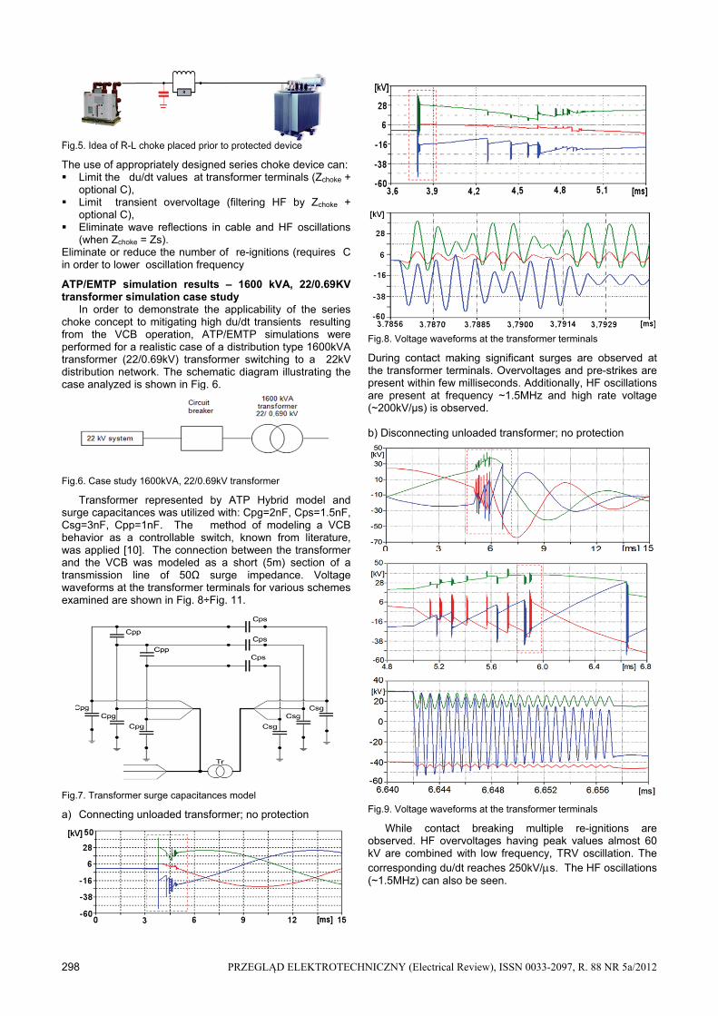
Fig.5. Idea of R-L choke placed prior to protected device
The use of appropriately designed series choke device can: Limit the du/dt values at transformer terminals (Zchoke +
optional C), Limit transient overvoltage (filtering HF by Zchoke +
optional C), Eliminate wave reflections in cable and HF oscillations
(when Zchoke = Zs). Eliminate or reduce the number of re-ignitions (requires C in order to lower oscillation frequency
ATP/EMTP simulation results – 1600 kVA, 22/0.69KV transformer simulation case study
In order to demonstrate the applicability of the series choke concept to mitigating high du/dt transients resulting from the VCB operation, ATP/EMTP simulations were performed for a realistic case of a distribution type 1600kVA transformer (22/0.69kV) transformer switching to a 22kV distribution network. The schematic diagram illustrating the case analyzed is shown in Fig. 6.
Fig.6. Case study 1600kVA, 22/0.69kV transformer
Transformer represented by ATP Hybrid model and surge capacitances was utilized with: Cpg=2nF, Cps=1.5nF, Csg=3nF, Cpp=1nF. The method of modeling a VCB behavior as a controllable switch, known from literature, was applied [10]. The connection between the transformer and the VCB was modeled as a short (5m) section of a transmission line of 50Ω surge impedance. Voltage waveforms at the transformer terminals for various schemes examined are shown in Fig. 8÷Fig. 11.
Fig.7. Transformer surge capacitances model
a) Connecting unloaded transformer; no protection
Fig.8. Voltage waveforms at the transformer terminals
During contact making significant surges are observed at the transformer terminals. Overvoltages and pre-strikes are present within few milliseconds. Additionally, HF oscillations are present at frequency ~1.5MHz and high rate voltage (~200kV/µs) is observed. b) Disconnecting unloaded transformer; no protection
(1)
Fig.9. Voltage waveforms at the transformer terminals
While contact breaking multiple re-ignitions are observed. HF overvoltages having peak values almost 60 kV are combined with low frequency, TRV oscillation. The corresponding du/dt reaches 250kV/s. The HF oscillations (~1.5MHz) can also be seen.
PRZEGLĄD ELEKTROTECHNICZNY (Electrical Review), ISSN 0033-2097, R. 88 NR 5a/2012 299
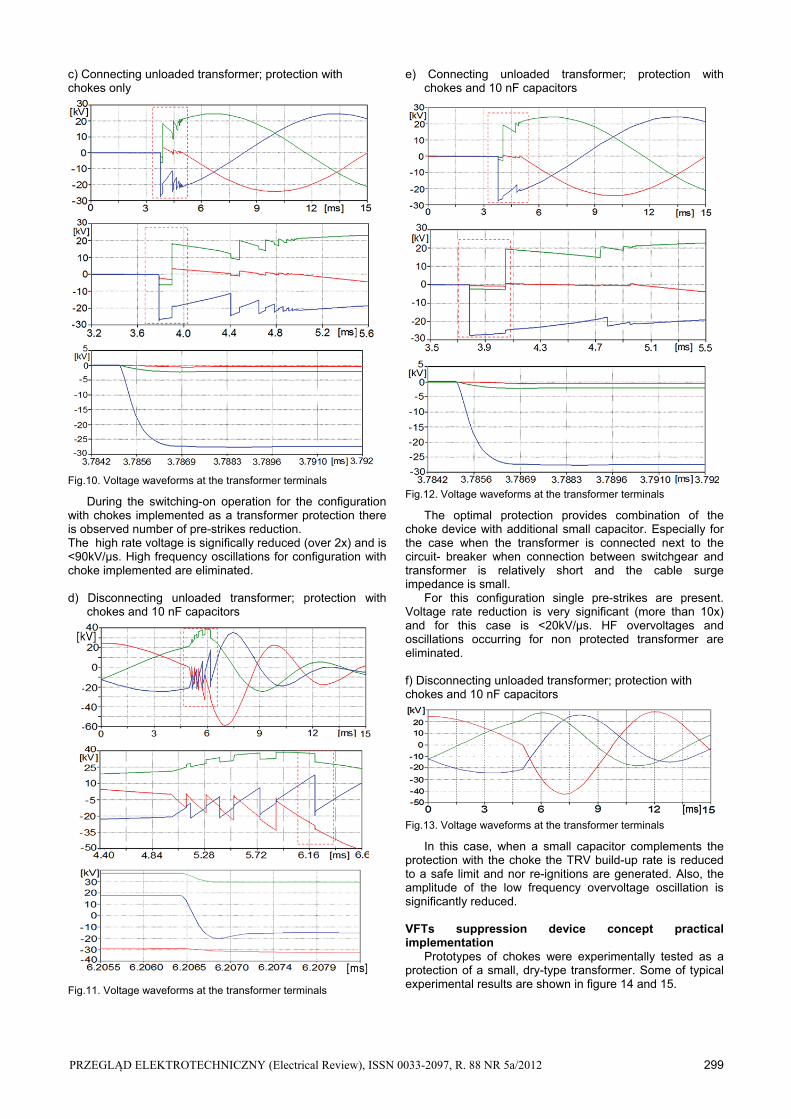
c) Connecting unloaded transformer; protection with chokes only
Fig.10. Voltage waveforms at the transformer terminals
During the switching-on operation for the configuration with chokes implemented as a transformer protection there is observed number of pre-strikes reduction. The high rate voltage is significally reduced (over 2x) and is <90kV/µs. High frequency oscillations for configuration with choke implemented are eliminated. d) Disconnecting unloaded transformer; protection with chokes and 10 nF capacitors
Fig.11. Voltage waveforms at the transformer terminals
e) Connecting unloaded transformer; protection with chokes and 10 nF capacitors
Fig.12. Voltage waveforms at the transformer terminals
The optimal protection provides combination of the choke device with additional small capacitor. Especially for the case when the transformer is connected next to the circuit- breaker when connection between switchgear and transformer is relatively short and the cable surge impedance is small.
For this configuration single pre-strikes are present. Voltage rate reduction is very significant (more than 10x) and for this case is <20kV/µs. HF overvoltages and oscillations occurring for non protected transformer are eliminated. f) Disconnecting unloaded transformer; protection with chokes and 10 nF capacitors
Fig.13. Voltage waveforms at the transformer terminals
In this case, when a small capacitor complements the protection with the choke the TRV build-up rate is reduced to a safe limit and nor re-ignitions are generated. Also, the amplitude of the low frequency overvoltage oscillation is significantly reduced. VFTs suppression device concept practical implementation Prototypes of chokes were experimentally tested as a protection of a small, dry-type transformer. Some of typical experimental results are shown in figure 14 and 15.

300 PRZEGLĄD ELEKTROTECHNICZNY (Electrical Review), ISSN 0033-2097, R. 88 NR 5a/2012
Fig.14. High frequency transients occurring in the power network during switching – on: a) without protection b) with choke and small capacitor protection
Fig.15. Voltage rate reduction of a single pre-strike
The experimental results confirmed the applicability of the series-choke protection concept to mitigating high du/dt transients resulting from the VCB switching operations.
In cases when the transformer internal capacitance is low, which is the case especially for dry-type transformers, additional small surge capacitor plays an important role in the transients suppression. It has to be pointed out, that the value of the capacitance used was more than an order of magnitude smaller, than typical the value of the typical snubber capacitor.
Figure 16 shows one of the first pilot installations of the series choke-based protection for a small transformer in the wind farm in Poland.
Fig. 16 VFTs suppression device pilot installation
Conclusions The problem of potential VFT-related hazard to transformer and other power equipment resulting from switching operations was demonstrated on a practical example. A new mitigation method against these hazards in a form of a series-connected choke element was shown. It was demonstrated that the use of the choke significally reduces voltage steepness and number of re-ignitions generated during transformer operated through the VCBs. Additionally there is observed noticeable overvoltage reduction. The number of pre-strikes during contact making was reduced and high frequency oscillations were practically eliminated. The practical case analysis using ATP/EMTP simulations demonstrated that in some cases (especially when a short connection between the transformer and the VCB exist), the voltage steepness as high as ~250kV/µs was simulated. This du/dt was over 2 times reduced with the use of the chokes only. Further reduction was achieved when a small (10nF) surge capacitors were used. In this case the du/dt was reduced below 20kV/µs. Additionally, the small surge capacitor significantly reduces LF overvoltages (45kV) and helps to eliminate the re-ignitions. Prototypes of chokes were experimentally tested and confirmed the applicability of the series-choke protection concept to mitigating high du/dt transients resulting from the VCB switching operations.
LITERATURE
[1] CIGRE working group A2-A3-B3.21, Electrical Environment of Transformers; Impact of fast transients”, ELECTRA 208, (2005)
[2] Lopez–Roldan J., De Herdt H., Min J., Van Velthove R., Decklerq J., Sels T., Karas J., Van Dommelen D., Popow P., Van der Sluis L., Aquado M., Study of interaction between distribution transformer and vacuum circuit breaker, Proceedings of 13th ISH (2003), pp. 62÷64
[3] Morched A. S., Marti L., Brierly R. H., Lackey J. G., Analysis of Internal Winding Stresses in EHV Generator Set-Up Transformer Failures, IEEE Trans. on Power Delivery, Vol. 11, No. 2, (1996), pp. 888÷894
[4] Popov M., Acha E., Overvoltages due to switching off an unloaded transformer with a vacuum circuit breaker, IEEE Trans. on Power Delivery, Vol. 14, No. 4, (1999), pp. 1317÷1322
[5] Burrage L. M., Shaw J. H., McConnell B. W., Distribution transformer performance when subjected to steep front impulses, IEEE Trans. on Power Delivery, Vol. 5, No. 2, (1990)
[6] Piasecki W., Bywalec G., Florkowski M., Fulczyk M., Furgal J., New approach towards Very Fast Transients suppression, Proceedings of IPST’2007
[7] Paul D., Failure Analysis of Dry-Type Power Transformer, IEEE Transaction on Industry Applications, Vol. 37, No. 3, (2001)
[8] Wong S. M., Snider L. A., Lo E. W. C., Overvoltages and reignition behavior of vacuum circuit breaker, Proceedings of IPST’2003
Autorzy: Dariusz Smugała, Ph.D. Eng., E-mail: [email protected] Wojciech Piasecki, Ph.D.Eng., E-mail: [email protected] Magdalena Ostrogórska, Ms.C.Eng. E-mail: [email protected] Marek Florkowski, Ph.D.Eng., E-mail: [email protected] Marek Fulczyk, Ph.D.Eng., E-mail: [email protected] ABB Corporate Research Center, Starowiślna 13 A Str., 31-038 Cracow, Poland, Paweł Kłys, Ms.C.Eng., ABB Transformers, Aleksandrowska 67/93 Str., 91-205 Lodz, Poland, E-mail: [email protected]