distribution of belt anchorage locations in the second...
TRANSCRIPT
ABSTRACT
Seat belt anchorage locations have a strong effect on occupant protection. Federal Motor Vehicle Safety Standard (FMVSS) 210 specifies requirements for the layout of the anchorages relative to the seating reference point and seat back angle established by the SAE J826 H-point manikin. Sled testing and computational simulation has established that belt anchorage locations have a strong effect on occupant kinematics, particularly for child occupants using the belt as their primary restraint. As part of a larger study of vehicle geometry, the locations of the anchorage points in the second-row, outboard seating positions of 83 passenger cars and light trucks with a median model year of 2005 were measured. The lower anchorage locations spanned the entire range of lap belt angles permissible under FMVSS 210 and the upper anchorages (D-ring locations) were distributed widely as well. Combined with the findings from concurrent research on the effects of belt geometry, these results suggest that occupant kinematics in frontal impact can be expected to differ widely across vehicles due to differences in belt geometry.
INTRODUCTION
In the United States, the locations of the anchorages of seat belt systems are regulated by Federal Motor Vehicle Safety Standard (FMVSS) 210. Anchorage locations are referenced to the seating reference point (SgRP), which is measured using the SAE J826 H-point manikin. The H-point manikin torso line is also interpreted as the seat back angle for purposes of
FMVSS 210. In vehicle design, a two-dimensional template representing the profile of the J826 H-point machine is often used. This template, which is depicted schematically FMVSS 210, is used to define the upper anchorage location range. Lap belt anchorages must be positioned such that a vector from the anchorage to the SgRP in side view forms an angle of between 30 and 75 degrees with the horizontal. Upper anchorages must be located within a side-view zone defined with respect to the SAE J826 two-dimensional template with the template H-point aligned with the SgRP.
Recent work at the University of Michigan Transportation Research Institute (UMTRI) has demonstrated that belt anchorage locations have a strong effect on occupant kinematics [1,4,5]. More-rearward or higher lower anchorages (flatter lap belt angles) tend to reduce lower-body excursion, except when submarining occurs due to the belt slipping off the pelvis and into the abdomen. More-forward and higher upper anchorage locations tend to increase head excursion, except when submarining occurs.
As part of a broader effort to improve the protection of child passengers who use the belt for primary restraint, UMTRI has undertaken a series of studies that have included measurements of the rear-seat environment, with a focus on the second row [3, 11]. Second-row seat cushions are much longer than the typical thigh lengths of children younger than 12 years. Long seats are associated with slouching, more-forward hip locations, and poorer belt fit [7, 13].
Distribution of Belt Anchorage Locations in the Second Row of Passenger Cars and Light Trucks
2013-01-1157
Published04/08/2013
Matthew ReedUniv. of Michigan
Sheila Ebert-HamiltonUMTRI
Copyright © 2013 SAE International
doi:10.4271/2013-01-1157
THIS DOCUMENT IS PROTECTED BY U.S. AND INTERNATIONAL COPYRIGHT.It may not be reproduced, stored in a retrieval system, distributed or transmitted, in whole or in part, in any form or by any means.
Downloaded from SAE International by Matthew Reed, Monday, April 01, 2013 03:05:22 PM
The current analysis examines the locations of belt anchorages in second-row, outboard seating positions. As part of several vehicle-measurement projects, the seating environment in the second rows of 84 vehicles was measured. The belt-anchorage locations are compared with the FMVSS 210 criteria.
METHODS
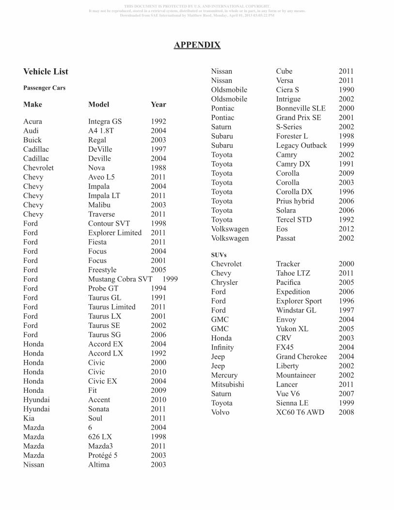
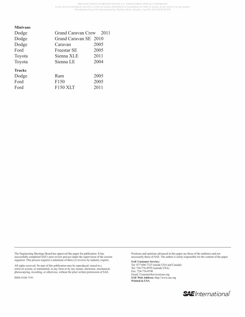
The anchorage locations of the driver-side, second-row passenger positions of a convenience sample of eighty-three passenger vehicles with rear seats were measured between 2007-2011. The sample consisted of 57 passenger cars, 17 SUVs, 6 minivans, and 3 pickup trucks, of which sixty-six were model year 2000 or newer, and 8 were model year 1995 or older. A complete list of the vehicles is in Appendix A.
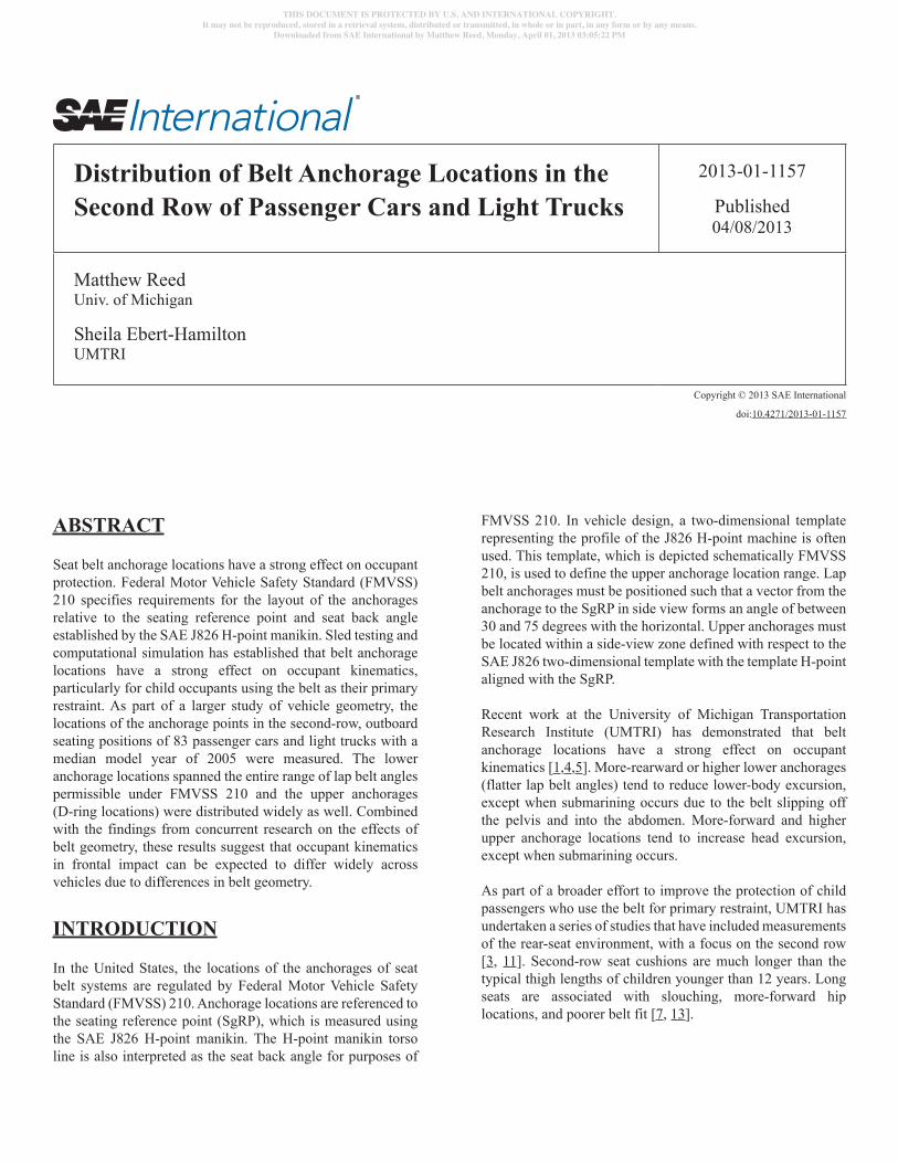
Figure 1. CMM (FARO Arm) attached to a vehicle.
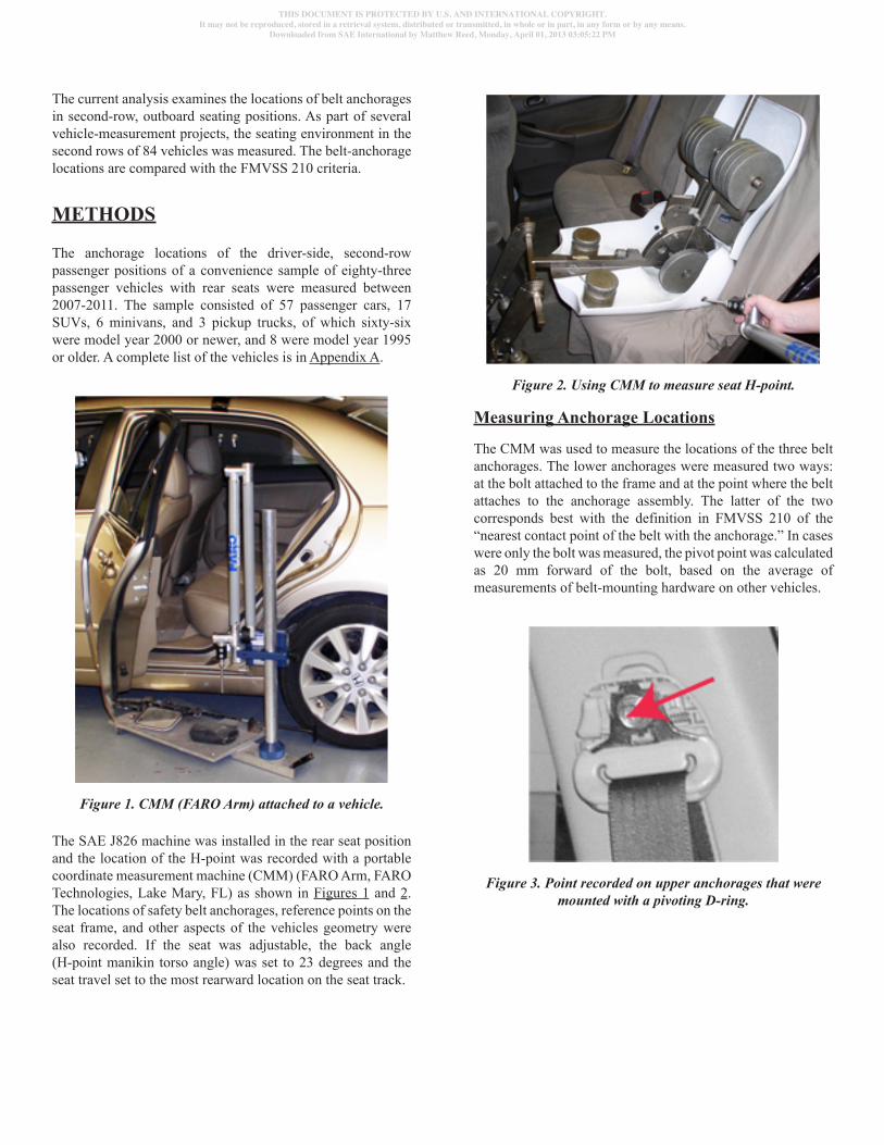
The SAE J826 machine was installed in the rear seat position and the location of the H-point was recorded with a portable coordinate measurement machine (CMM) (FARO Arm, FARO Technologies, Lake Mary, FL) as shown in Figures 1 and 2. The locations of safety belt anchorages, reference points on the seat frame, and other aspects of the vehicles geometry were also recorded. If the seat was adjustable, the back angle (H-point manikin torso angle) was set to 23 degrees and the seat travel set to the most rearward location on the seat track.
Figure 2. Using CMM to measure seat H-point.
Measuring Anchorage Locations
The CMM was used to measure the locations of the three belt anchorages. The lower anchorages were measured two ways: at the bolt attached to the frame and at the point where the belt attaches to the anchorage assembly. The latter of the two corresponds best with the definition in FMVSS 210 of the “nearest contact point of the belt with the anchorage.” In cases were only the bolt was measured, the pivot point was calculated as 20 mm forward of the bolt, based on the average of measurements of belt-mounting hardware on other vehicles.
Figure 3. Point recorded on upper anchorages that were mounted with a pivoting D-ring.
THIS DOCUMENT IS PROTECTED BY U.S. AND INTERNATIONAL COPYRIGHT.It may not be reproduced, stored in a retrieval system, distributed or transmitted, in whole or in part, in any form or by any means.
Downloaded from SAE International by Matthew Reed, Monday, April 01, 2013 03:05:22 PM
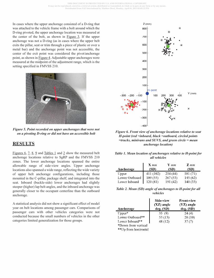
In cases where the upper anchorage consisted of a D-ring that was attached to the vehicle frame with a bolt around which the D-ring pivoted, the upper anchorage location was measured at the center of the bolt, as shown in Figure 3. If the upper anchorage was not a D-ring (as in cases where the upper belt exits the pillar, seat or trim through a piece of plastic or over a metal bar) and the anchorage point was not accessible, the center of the exit point was considered the pivot/anchorage point, as shown in Figure 4. Adjustable upper anchorages were measured at the midpoint of the adjustment range, which is the setting specified in FMVSS 210.
Figure 5. Point recorded on upper anchorages that were not on a pivoting D-ring or did not have an accessible bolt
RESULTS
Figures 6, 7, 8, 9 and Tables 1 and 2 show the measured belt anchorage locations relative to SgRP and the FMVSS 210 zones. The lower anchorage locations spanned the entire allowable range of side-view angles. Upper anchorage locations also spanned a wide range, reflecting the wide variety of upper belt anchorage configurations, including those mounted in the C-pillar, package shelf, and integrated into the seat. Inboard (buckle-side) lower anchorages had slightly steeper (higher) lap belt angles, and the inboard anchorage was generally closer to the occupant centerline than the outboard anchorage.
A statistical analysis did not show a significant effect of model year on belt locations among passenger cars. Comparisons of passenger cars with other vehicles categories were not conducted because the small numbers of vehicles in the other categories limited generalization for those groups.
Figure 6. Front view of anchorage locations relative to seat H-point (red =inboard, black =outboard, circled points =trucks, minivans and SUVS, and green circle = mean
anchorage location)
Table 1. Mean location of anchorages relative to H-point for all vehicles
Table 2. Mean (SD) angle of anchorages to H-point for all vehicles
THIS DOCUMENT IS PROTECTED BY U.S. AND INTERNATIONAL COPYRIGHT.It may not be reproduced, stored in a retrieval system, distributed or transmitted, in whole or in part, in any form or by any means.
Downloaded from SAE International by Matthew Reed, Monday, April 01, 2013 03:05:22 PM
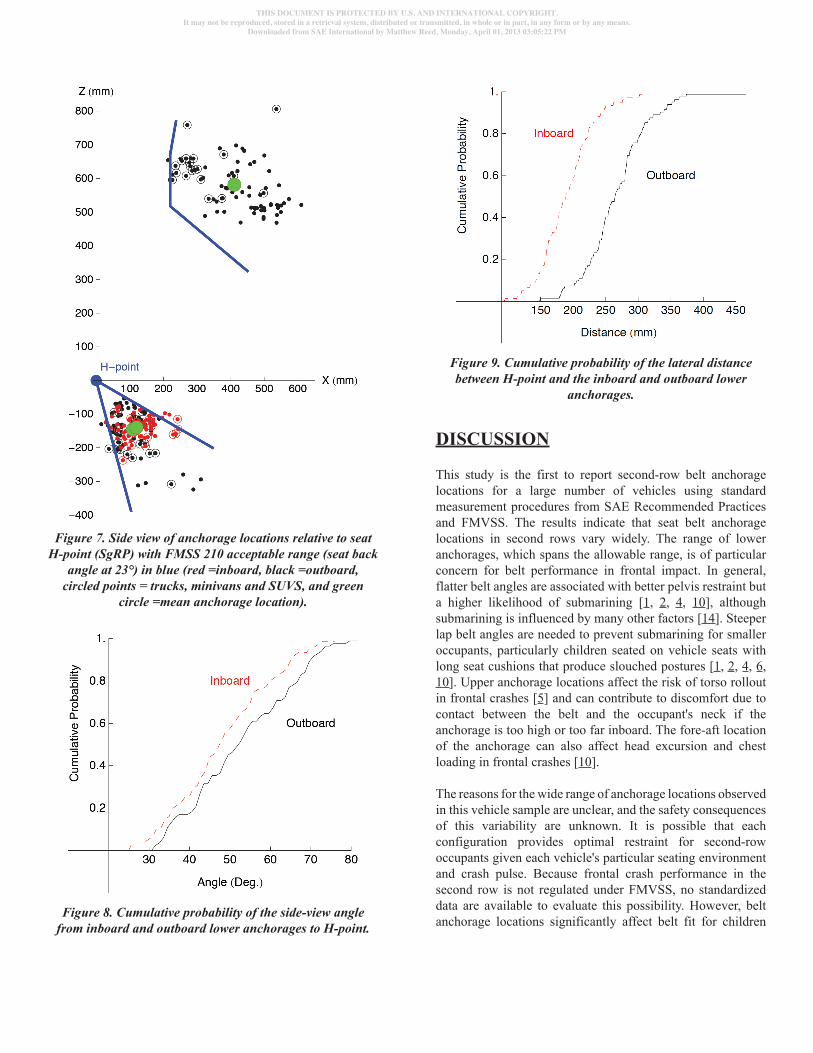
Figure 7. Side view of anchorage locations relative to seat H-point (SgRP) with FMSS 210 acceptable range (seat back
angle at 23°) in blue (red =inboard, black =outboard, circled points = trucks, minivans and SUVS, and green
circle =mean anchorage location).
Figure 8. Cumulative probability of the side-view angle from inboard and outboard lower anchorages to H-point.
Figure 9. Cumulative probability of the lateral distance between H-point and the inboard and outboard lower
anchorages.
DISCUSSION
This study is the first to report second-row belt anchorage locations for a large number of vehicles using standard measurement procedures from SAE Recommended Practices and FMVSS. The results indicate that seat belt anchorage locations in second rows vary widely. The range of lower anchorages, which spans the allowable range, is of particular concern for belt performance in frontal impact. In general, flatter belt angles are associated with better pelvis restraint but a higher likelihood of submarining [1, 2, 4, 10], although submarining is influenced by many other factors [14]. Steeper lap belt angles are needed to prevent submarining for smaller occupants, particularly children seated on vehicle seats with long seat cushions that produce slouched postures [1, 2, 4, 6, 10]. Upper anchorage locations affect the risk of torso rollout in frontal crashes [5] and can contribute to discomfort due to contact between the belt and the occupant's neck if the anchorage is too high or too far inboard. The fore-aft location of the anchorage can also affect head excursion and chest loading in frontal crashes [10].
The reasons for the wide range of anchorage locations observed in this vehicle sample are unclear, and the safety consequences of this variability are unknown. It is possible that each configuration provides optimal restraint for second-row occupants given each vehicle's particular seating environment and crash pulse. Because frontal crash performance in the second row is not regulated under FMVSS, no standardized data are available to evaluate this possibility. However, belt anchorage locations significantly affect belt fit for children
THIS DOCUMENT IS PROTECTED BY U.S. AND INTERNATIONAL COPYRIGHT.It may not be reproduced, stored in a retrieval system, distributed or transmitted, in whole or in part, in any form or by any means.
Downloaded from SAE International by Matthew Reed, Monday, April 01, 2013 03:05:22 PM
and adults, with flatter lap belt angles associated with poorer lap belt fit relative to the pelvis [12, 13]. Sled testing at UMTRI with a range of belt conditions in exemplar second-row seats has shown the belt anchorage locations strongly influence the kinematics of 6YO and 10YO Hybrid-III ATDs [5, 10], although these findings are limited by the biofidelity of the Hybrid-III ATDs, particularly with respect to submarining [6]. Optimization studies using computer simulation have shown that optimal belt anchorage locations for children using the belt as primary restraint are different from those of adults [1], highlighting the challenge of optimizing restraints in the second row, where half of crash-involved occupants are age 12 and younger [7].
These data are limited by the sample of vehicles, which was assembled largely by convenience. No effort was made to compare belt geometry between passenger cars and other categories of vehicles, for example, because the small numbers of vehicles in other categories and the lack of a meaningful weighting scheme meant that the results by vehicle category could not be generalized. However, the relatively large size of the database suggests that the results may be broadly representative of the U.S. vehicle fleet, particularly for passenger cars.
Each measurement was made in a single exemplar vehicle in use, which may differ due to manufacturing and use variability from other nominally identical vehicles. The anchorages were located relative to a single H-point measurement; variability in H-point location would contribute to anchorage location variability, but that effect would be small relative to the range of anchorage locations observed across vehicles. Access to the belt anchorages, particularly the inboard (buckle) and upper anchorage was challenging in many vehicles. Some judgment was exercised in determining the appropriate point to record for each anchorage. For any individual vehicle, this could lead to the measurements differing from the design intent or from what another team would measure. These effects would be expected to be small relative to the range observed, although they could contribute a systematic bias.
Further research is needed to determine whether second-row belt anchorages could be better located to improve occupant protection. Many considerations come into play, including the need to secure child restraints using belts, the availability of appropriate vehicle structure for belt attachments, the desire for seats that can be folded and stowed, and the relatively low occupancy rates in rear seats.
REFERENCES
1. Hu, J., Wu, J., Reed, M.P., Klinich, K.D., and Cao, L. (in press). Rear seat restraint system optimization for older children in frontal crashes. 7UDI¿F�,QMXU\�3UHYHQWLRQ.
2. Hu, J., Klinich, K.D., Reed, M.P., Kokkolaras, M., and Rupp, J.D. (2012). Development and validation of D�PRGL¿HG�+\EULG�,,,�VL[�\HDU�ROG�GXPP\�PRGHO�IRU�simulating submarining in motor-vehicle crashes. 0HGLFDO�(QJLQHHULQJ�DQG�3K\VLFV� 34(5):541-551. 10.1016/j.medengphy.2011.08.013.
3. Huang, S. and Reed, M., “Comparison of Child Body Dimensions with Rear Seat Geometry,” SAE Technical Paper 2006-01-1142, 2006, doi:10.4271/2006-01-1142.
4. Klinich, K.D., Reed, M.P., Ebert, S.M., and Rupp, J.D. (2011). Effect of Realistic Vehicle Seats, Cushion Length, and Lap Belt Geometry on Child ATD Kinematics. Technical Report 2011-20. University of Michigan Transportation Research Institute, Ann Arbor, MI.
5. Klinich, K.D., Reed, M.P., Orton, N.R., Manary, M.A., and Rupp, J.D. (2011). Optimizing Protection for Rear Seat Occupants: Assessing Booster Performance with Realistic Belt Geometry using the Hybrid-III 6YO ATD. Technical Report 2011-40. University of Michigan Transportation Research Institute, Ann Arbor, MI.
6. Klinich, K. D., Reed, M. P, Manary, M.A., Orton, N.R. (2010). Development and testing of a more realistic pelvis for the Hybrid III 6YO ATD. 7UDI¿F�,QMXU\�3UHYHQWLRQ, 11(6):606-12.
7. Klinich, K.D. and Flannagan, C.A.C. (2009). Identifying priorities for improving rear-seat occupant protection. UMTRI Technical Report 2009-46. University of Michigan Transportation Research Institute, Ann Arbor, MI.
8. Reed, M.P., Ebert-Hamilton, S.M., and Schneider, L.W. (2005). Development of ATD installation procedures based on rear-seat occupant postures. Stapp Car Crash Journal, 49: 381-421.
9. Reed, M.P., Ebert-Hamilton, S.M., Manary, M.A., Klinich, K.D., and Schneider, L.W. (2006). Improved positioning procedures for 6YO and 10YO ATDs based on child occupant postures. 6WDSS�&DU�&UDVK�-RXUQDO, 50: 337-388.
10. Reed, M.P., Ebert-Hamilton, S.M., Klinich, K.D., Manary, M.A., and Rupp, J.D. (2008). Assessing Child Belt Fit, Volume I: Effects of Vehicle Seat and Belt Geometry on Belt Fit for Children with and without Belt Positioning Booster Seats. Technical Report UMTRI- 2008-49-1. University of Michigan Transportation Research Institute, Ann Arbor, MI.
THIS DOCUMENT IS PROTECTED BY U.S. AND INTERNATIONAL COPYRIGHT.It may not be reproduced, stored in a retrieval system, distributed or transmitted, in whole or in part, in any form or by any means.
Downloaded from SAE International by Matthew Reed, Monday, April 01, 2013 03:05:22 PM
11. Klinich, K.D., Ebert-Hamilton, S.M., Reed, M.P., Manary, M.A., and Rupp, J.D. (2008). Assessing Child Belt Fit, 9ROXPH�,,��(IIHFWV�RI�5HVWUDLQW�&RQ¿JXUDWLRQ��%RRVWHU�6HDW�Designs, Seating Procedure, and Belt Fit on the Dynamic Response of the Hybrid-III 10-year-old ATD in Sled Tests. Technical Report UMTRI-2008-49-2. University of Michigan Transportation Research Institute, Ann Arbor, MI.
����5HHG��0���³0HDVXUHPHQW�RI�WKH�&RQWRXU�DQG�'HÀHFWLRQ�RI�Vehicle Seats for Comparison with the FMVSS 213 Dynamic Test Bench,” SAE Technical Paper 2011-01-0265, 2011, doi:10.4271/2011-01-0265.
13. Reed, M.P., Ebert-Hamilton, S.M., and Rupp, J.D. (2012). (IIHFWV�RI�REHVLW\�RQ�VHDW�EHOW�¿W��7UDI¿F�,QMXU\�3UHYHQWLRQ, 13(4):364-372. 10.1080/15389588.2012.659363
14. Reed, M.P., Ebert-Hamilton, S.M., Klinich, K.D., Manary, M.A., and Rupp, J.D. (in press). Effects of vehicle seat and EHOW�JHRPHWU\�RQ�EHOW�¿W�IRU�FKLOGUHQ�ZLWK�DQG�ZLWKRXW�EHOW�positioning booster seats. $FFLGHQW�$QDO\VLV�DQG�3UHYHQWLRQ� 10.1016/j.aap.2012.05.030
15. Rouhana, S., Viano, D., Jedrzejczak, E., and McCleary, J., “Assessing Submarining and Abdominal Injury Risk in the Hybrid III Family of Dummies,” SAE Technical Paper 892440, 1989, doi:10.4271/892440.
THIS DOCUMENT IS PROTECTED BY U.S. AND INTERNATIONAL COPYRIGHT.It may not be reproduced, stored in a retrieval system, distributed or transmitted, in whole or in part, in any form or by any means.
Downloaded from SAE International by Matthew Reed, Monday, April 01, 2013 03:05:22 PM
APPENDIX
Vehicle List
Passenger Cars
Make Model Year
Acura Integra GS 1992Audi A4 1.8T 2004Buick Regal 2003Cadillac DeVille 1997Cadillac Deville 2004Chevrolet Nova 1988Chevy Aveo L5 2011Chevy Impala 2004Chevy Impala LT 2011Chevy Malibu 2003Chevy Traverse 2011Ford Contour SVT 1998Ford Explorer Limited 2011Ford Fiesta 2011Ford Focus 2004Ford Focus 2001Ford Freestyle 2005Ford Mustang Cobra SVT 1999Ford Probe GT 1994Ford Taurus GL 1991Ford Taurus Limited 2011Ford Taurus LX 2001Ford Taurus SE 2002Ford Taurus SG 2006Honda Accord EX 2004Honda Accord LX 1992Honda Civic 2000Honda Civic 2010Honda Civic EX 2004Honda Fit 2009Hyundai Accent 2010Hyundai Sonata 2011Kia Soul 2011Mazda 6 2004Mazda 626 LX 1998Mazda Mazda3 2011Mazda Protégé 5 2003Nissan Altima 2003
Nissan Cube 2011Nissan Versa 2011Oldsmobile Ciera S 1990Oldsmobile Intrigue 2002Pontiac Bonneville SLE 2000Pontiac Grand Prix SE 2001Saturn S-Series 2002Subaru Forester L 1998Subaru Legacy Outback 1999Toyota Camry 2002Toyota Camry DX 1991Toyota Corolla 2009Toyota Corolla 2003Toyota Corolla DX 1996Toyota Prius hybrid 2006Toyota Solara 2006Toyota Tercel STD 1992Volkswagen Eos 2012Volkswagen Passat 2002
SUVsChevrolet Tracker 2000Chevy Tahoe LTZ 2011&KU\VOHU� 3DFL¿FD� ����Ford Expedition 2006Ford Explorer Sport 1996Ford Windstar GL 1997GMC Envoy 2004GMC Yukon XL 2005Honda CRV 2003,Q¿QLW\� );��� ����Jeep Grand Cherokee 2004Jeep Liberty 2002Mercury Mountaineer 2002Mitsubishi Lancer 2011Saturn Vue V6 2007Toyota Sienna LE 1999Volvo XC60 T6 AWD 2008
THIS DOCUMENT IS PROTECTED BY U.S. AND INTERNATIONAL COPYRIGHT.It may not be reproduced, stored in a retrieval system, distributed or transmitted, in whole or in part, in any form or by any means.
Downloaded from SAE International by Matthew Reed, Monday, April 01, 2013 03:05:22 PM
The Engineering Meetings Board has approved this paper for publication. It has successfully completed SAE’s peer review process under the supervision of the session organizer. This process requires a minimum of three (3) reviews by industry experts.
All rights reserved. No part of this publication may be reproduced, stored in a retrieval system, or transmitted, in any form or by any means, electronic, mechanical, photocopying, recording, or otherwise, without the prior written permission of SAE.
ISSN 0148-7191
Positions and opinions advanced in this paper are those of the author(s) and not necessarily those of SAE. The author is solely responsible for the content of the paper.
SAE Customer Service:Tel: 877-606-7323 (inside USA and Canada)Tel: 724-776-4970 (outside USA)Fax: 724-776-0790Email: [email protected] Web Address: http://www.sae.orgPrinted in USA
MinivansDodge Grand Caravan Crew 2011Dodge Grand Caravan SE 2010Dodge Caravan 2005Ford Freestar SE 2005Toyota Sienna XLE 2011Toyota Sienna LE 2004
TrucksDodge Ram 2005Ford F150 2005Ford F150 XLT 2011
THIS DOCUMENT IS PROTECTED BY U.S. AND INTERNATIONAL COPYRIGHT.It may not be reproduced, stored in a retrieval system, distributed or transmitted, in whole or in part, in any form or by any means.
Downloaded from SAE International by Matthew Reed, Monday, April 01, 2013 03:05:22 PM