distributed solutions for grid control - stanford...
TRANSCRIPT

Distributed Solutions for Grid Control
GCEP WorkshopNov 1-2, 2007
Dr. Deepak Divan School of Electrical Engineering
Georgia Institute of Technology, Atlanta, GA, USA
777 Atlantic Drive [email protected], GA

Confidential
Intelligent Power Infrastructure Consortium – Research Thrusts
Sensors, Communications,
Neural Nets, Monitoring
Power Systems
Engineering
PowerElectronics,Drives, Controls
Power line sensornetsWide area monitoringDistributed power line sensing
Power line communicationsNeural nets for system I/D and control
Wireless sensor networksSensorless motor fault detectionUnscheduled down-time identification
Neural network controls for PEComponent failure predictionPower and analog ICs
Active filtersMotor DrivesCurrent surge limitersHigh power inverters & dc/dc converters
D-FACTS devicesCurrent limiting conductorsFault current limitersPower quality and reliability
Wide area controlWide area protection
Power system operation and state estimation Protective relayingBulk power system reliability
Congestion managementSystem control and stability with FACTSDistributed energy sources
UTILITY APPLNS INDUSTRIAL APPLNS

Confidential

Confidential
Axioms for Smart-Grid Design• Achieving a sustainable energy infrastructure will
require an efficient, flexible, dynamic, fault tolerant and reliable electricity delivery network.
• Unlike other modern networks, the power grid lacks distributed intelligence and automation, resulting in poor reliability and asset utilization
• A complete replacement of the electricity infrastructure seems unjustified as there is no performance metric, e.g. ‘bandwidth’, that promises orders of magnitude improvementThis leads to several fundamental tenets for Smart Grid design.
• Changes in infrastructure will have to be incrementally built to enhance and augment the legacy infrastructure
• Solutions cannot degrade the intrinsic reliability of the system – high system reliability through redundancy and fail-safe modes.
• Resulting grid needs to be self-healing, exhibiting graceful degradation as communications and vital elements are lost

Confidential
The Future is Massively Distributed!
• Transformation of communications and computing sectors has occurred because of the use of massively distributed solutions, e.g.
– Super-computers to Cluster-computers– Satellite communications to Cellular communications– Point to point communications to the Internet– Multiple individual sensors to Sensor networks or Sensornets
• Standard, redundant, mass-manufactured parts in smart networks result in system performance and reliability gains while realizing lower cost.
• The new networks are robust and resilient and reorganize themselves as units fail.
• Systems continue to operate at basic sub-optimal levels as communication links fail.
• System exhibits graceful degradation and provides visibility to operator even as the main system fails.
• The sustainable energy infrastructure is predicated upon distributed sources and distributed smart loads, but the power delivery infrastructure is designed to operate with single point hierarchical control – is this the weak link?

Confidential
I-Grid – A Distributed Grid Monitoring Solution
$250 per sensor
ISP
ISPWAN
Provider
DA
TA IN
GE
STO
R
DYNAMIC
REAL-TIME
DATABASE
STATIC
DATABASE
WEB
ACCESS
FLEXIBLE
NOTIFI-
CATION
ENGINE
OTHER
DATABASES DATA
EXPORT
INTERNET
OR
INTRANET
WIRELESS
CONNECT
I-GRID PLATFORMREMOTE
MONITORS
REMOTE
USERS
WEB BROWSER
NOTIFICATION
UTILITY STAFF
& CUSTOMERS
END-USER
REPORTS
INTERNET
Courtesy: Soft Switching Technologies

Confidential
Wide Area Monitoring – August 2003 Blackout
Frequency data recorded by I-Grid on August 14, 2003
Data was available within minutes of the blackout. Cost was under $200 per monitored point.

Confidential
Power Line Sensornets
• Low-cost couplers that perform sensing, power scavenging and communications functions
• Operate as a self-organizing sensor network that performs distributed condition monitoring of the entire length of the power line
• Sensing of dynamic line capacity, imminent vegetation contact, failing insulators, security risks
• Improve system reliability and asset utilization
• Sensors that perform sensing, power scavenging and communications functions exist today – the cost is still too high
• Moving towards self-organizing sensor networks that perform distributed condition monitoring of the entire length of the power line
• Target functions include sensing of dynamic line capacity, power theft, imminent vegetation contact, failing insulators, security risks
• Objective: Improved system reliability and asset utilization
Courtesy: Protura
Confidential
Distributed Monitoring
• Distributed monitoring of the grid is rapidly becoming technically feasible. • Self-organizing ad-hoc sensor networks offer a new approach for realizing a
resilient and cost-effective distributed monitoring system• Distributed monitoring can enable several value streams – improved system
reliability, lower power theft, reduced downtime, improved asset utilization, and improved visibility/response to security threats
• Sensor and communication costs (including installation and operating costs) need to be extremely low
• Data latency, compaction and visualization are critical issues that need to be addressed.
• Having data on parameters such as the dynamic thermal capacity of a line can improve system utilization, but do we have the ‘muscle’ to realize the desired control for all lines in the system?

Confidential
Major Challenges for Power Delivery
• Existing infrastructure is aging and underutilized • New lines are expensive and difficult to get approved
(ROW & NIMBY)• As new generation and load is added, portions of the
grid are getting overloaded• Power flow in individual lines cannot be controlled.
This results in sub-optimal grid operation and poses significant operational challenges for utilities –
• Danger of load shedding and poor reliability under high-load and under contingency conditions
• Fault currents that may exceed safe levels• Lines that exceed thermal ratings, even as
neighboring lines are under-utilized• Conservative operation because of lack of visibility,
leading to significant under-utilization of assets• Inability to cope with dynamics and intermittencies
that are characteristic of a sustainable system.
Solutions are needed for improving the controllability and utilization of the power grid

Confidential
Typical Power Delivery Systems
Radial system
• Radial System– Easy to control power flow and node
voltage with conventional solutions such as tap changers, capacitors and phase shifting transformers
– Suffers from low system reliability under contingency conditions
• Meshed System or Network – Highest reliability due to redundancy of
transmission lines– Poor line utilization because current
flow in parallel lines cannot be controlled
– Difficult to satisfy voltage and line loading constraints simultaneously, even when grid state data is available.
Meshed system
Confidential
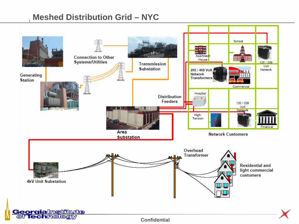
Meshed Distribution Grid – NYC

Confidential
Improving Grid Reliability and Utilization
• Reliable power is the paramount mission for a utility. • Cost and system-utilization can be more effectively controlled in radial
systems, whereas reliability of meshed networks is substantially higher. • However, it is difficult to control where current flows in a networked (meshed)
power system - results in loop flows, congestion and poor system utilization.
• In such networks, the first line that gets thermally limited constrains the power transfer capacity of the entire network.
• The real situation is worse, as (N-1) and (N-2) contingency conditions can result in overloaded lines and a cascading failure.
• Networks are often used in dense urban areas, such as New York, where reliability needs override asset utilization issues.
j16 Ω
j24 Ω
138kV∠0°
138kV∠7.75°675A
450A

Confidential
Other Issues Associated With Lack of Grid Control
• Static and dynamic balance of line currents under dynamic load, source and network conditions is not possible as there aren’t sufficient ‘control’ handles.
• Even if controllers could be deployed at every node, finding the optimal operating points would be difficult for a meshed network.
• Insufficient transmission capacity creates islanded networks that require higher level of generation reserves to ensure system reliability.
• Transmission constraints can limit ability of end-users to access low-cost generation, leading to higher costs.
• Building a new line can eliminate congestion, but will reduce line utilization and cost of electricity, making it harder to recover the investment!
• Utility operations are based on the assumption that it is not cost effective to control power flow along individual lines.
• Realizing dynamic control of power flows on the grid can have a profound impact on grid reliability, asset utilization and sustainability.

Confidential
Loading Levels for the IEEE 39 Bus System
•Poor line utilization, average of 59%
•(N-1) contingency reduces system capacity from 1904 MW to 1450 MW, utilization to 47%.

Confidential
Achieving Power Flow Control
LXVVP δsin21
12 =
• Active power flow can be controlled by changing the impedance of the line or the angle of bus voltages
• Conventional Solutions– Phase Shifting transformers: Expensive, dynamic
control is difficult– Shunt compensation: Provides voltage support
but does not have the ability to control real power flow
• Alternative Solution– Series compensation: Offers the strongest control
capability by dynamically changing the reactive line impedance Kalyan Sen Xian Tutorial

Confidential
Shunt vs. Series VARs for Power Flow Control
Simple two bus example with fixed voltage sources compares the power flow control using shunt or series VAR compensation
07.86.79 −∠006.79 ∠
0 10 20 30 40 50 60 70 8025
30
35
40
45
50
55
60
MWARS
MW
S T
hrou
gh L
ine
1 Series Compensation
Shunt Compensation
• Series VARs have a much stronger influence on the real power flow
• For series VARs, 8 MVAR increases power by 25 MW
• For shunt VARs, 80 MVAR increases power by 5 MW
• Decoupled control is needed –• Shunt VARs to control voltage • Series VARs to control power flow

Confidential
Existing Solutions for Increasing Grid Capacity
• Traditional solutions, such as new lines, are expensive and subject to siting and ROW delays. New lines also make system utilization worse.
• Shunt VAR compensation provides voltage support but has weak impact on controlling power flows in the system.
• Power flow control requires Series VAR Compensation – not widely used.
• Technology solutions such as Flexible AC Transmission Systems (FACTS) are well known and have been commercially available for >15 years.
Type Parameter FACTS Device
Type A – Series/Shunt P and Q UPFC
Type B - Series P TCSC, SSSC
Type C - Shunt Q SVC, Statcon

Confidential
Typical FACTS Configurations
Shunt Shunt
Series Series - Shunt

Confidential
Typical FACTS System
Series Series - ShuntEstablished in 1998, 160 MVA unit. This was the first UPFC installation in the World

Confidential
Experience With FACTS Devices
• High total cost of ownership. (The 200 MVA Marcy Convertible Static Compensator (CSC) cost $54 million.)
• High fault currents (60,000 Amps) and high voltage levels (1000 kV) make implementation of series FACTS systems difficult and expensive.
• Utilities are claiming reliability levels of ~96-98% for FACTS devices, significantly lower than the 99.999% reliability that is typical for the utility system itself.
• Highly customized and complex design of FACTS devices requires skilled work force in the field, normally not within a utility’s core competency.
• As a result, even though the technology is mature, significant market penetration has not occurred. There is an opportunity for a new paradigm in grid power flow control
STATCOM

Confidential
Distributed Solution for Series VARs – Smart Wires
• Distributed control of line impedances offers a new approach for controlling power flow in networked systems, allowing higher reliability & utilization
• Line impedance control is accomplished using a large number of ‘clamp-on’‘couplers’ (modules) that float on the line, electrically and mechanically.
• The modules use magnetic induction to increase or decrease line impedance, to ‘push’ current away from, or to ‘pull’ current into a line.
• Modules are ‘standardized’ and made in high volume using easily available low-cost components.
• Reliability is obtained through redundancy, where failure of individual modules has no impact on system operation.
• Smart Wires can be implemented using ‘passive’ or ‘active’ modules.
couplers

Confidential
Distributed Series Impedance – Passive Smart Wires
Power Line
Transformer
S1
Xc
XM
XL
R2
S
Inje
cted
Impe
danc
e
Indu
ctiv
eC
apac
itive
Controller
• Power flow control achieved through change of line impedance. • Injects series capacitance or inductance to change line impedance as needed.• A large number of modules realize gradual change in line impedance and increase
reliability. • A coupling device in the form of a Single Turn Transformer (STT) is used to inject
the required impedance.• System control and communications used to set level of injection.

Confidential
Distributed Series Reactance – Passive Smart Wires
I0 Ithermal
Line Current (ILine)
N Xm
Control
Power Line
Transformer
S1
XM
Power Supply
SM
• Simplest implementation of DSI, with inductive impedance injection (Current Limiting Conductor or CLiC) – functions as a current limiting system
• As current in a line approaches the thermal limit, CLiC modules incrementally turn on, diverting current to other under-utilized lines
• Increase in line impedance can be realized by injecting a pre-tuned value of magnetizing inductance of the STT
• Each module is triggered at a predefined set point to reflect a gradual increase in line impedance
• No communication required and the devices operate autonomously

Confidential
Can Smart Wires Work in Practical Systems?
138 kV 345 kV 765 kV Thermal Line Capacity 184 MVA 1195 MVA 6625 MVA Current carrying capacity 770 A 2000 A 5000 A # of conductors/ diameter (inches) 1/1.0 2/1.2 4/1.45 Reactance ohms/mile 0.79 0.60 0.54 Reactive voltage drop/mile 608 V 1200 V 2700 V 1% Compensation/mile 6.1 V 12 V 27 V Smart Wire kVA- 1% Comp/mile 14 kVA 72 kVA 400 kVA Total 10 kVA modules/mile/1% 1.4 7.2 40
Number of modules for 10% control on a 30 mile 138 kV line at 770A: 420 modules or 4.6 modules/phase/mile.

Confidential
Simulation Results – Passive Smart WiresIncrease in ATC by as much as 75%
0 0.5 1 1.5 2 2.50
0.25
0.5
0.75
1
Time (sec)
Line
Cur
rent
(KA)
Profile of Line 2 Current
DSR Active
548.7 A
750 A
624.2A
GeneratorTaken Off
Simplified Four Bus System
Contingency Condition: Generator Outage 20 40 60 80 100 120 140 160
20
40
60
80
100
120
140
160
Load 2 (MW)
Load
1 (M
W)
Increase in Transfer Capacity
Line 2 Overload
Line 5 Overload
Line 2,4 Overload
Line 2,5 Overload
Line 1,2,5 Overload
MVARMWPI
∆∆
=Network Performance Index:
Perf
orm
ance
Fac
tor
Inje
cted
MVA
Rs

Confidential
Prototype Passive Smart Wires Module Specifications
• Electrical– Operating : 161 KV / 1,000 A– Injected impedance= 10 mΩ per module– ACSR Conductor: Drake (795 Kcmil)
• R= 0.128Ω, X= 0.4Ω per mile– Fault level: 50,000 A
• Mechanical– Target weight per module: 120 lb (critical design parameter)– Packaging to avoid corona discharge, and other mechanical, thermal and
environmental issues

Confidential
CLiC Prototype

Confidential
Active Smart Wires
• Distributed Static Series Compensator (DSSC)– Active solution employing a synchronous voltage source inverter– Each module rated for 5 KVA (capable of injecting ± 4.6 V @ 1000 A)– Communication interface is required to realize the bi-directional control
Power supply
Main transformer
Filter
PWMInverter
DC Capacitor
V
ControlsCommunication
Module
Current feedbackLine Current

Confidential
Active Smart Wires Prototype – Experimental Waveforms
-600-500-400-300-200-100
0100200300400500600
-0.015 -0.01 -0.005 0 0.005 0.01 0.015 0.02
Time (s)
Cur
rent
(A) o
r V
olta
ge (V
)
I_total/2 I_1 (DSSC) I_2 (uncontrolled) V_DSSC*100
-800
-600
-400
-200
0
200
400
600
800
-0.015 -0.01 -0.005 0 0.005 0.01 0.015 0.02
Time (s)
Cur
rent
(A) o
r V
olta
ge (V
)
I_total/2 I_1 (DSSC) I_2 (uncontrolled) V_DSSC*100
Line2 Line1
(a)(b) (c)
-800
-600
-400
-200
0
200
400
600
800
-0.015 -0.01 -0.005 0 0.005 0.01 0.015 0.02
Time (s)
Cur
rent
(A) o
r V
olta
ge (V
)
I_total/2 I_1 (DSSC) I_2 (uncontrolled) V_DSSC*100
Line1-DSSCLine2
Injected Voltage x100 Min.
Module Rating: 1500 Amps @ 4.6 volts

Confidential
Smart Wires – Operational Benefits
• Ability to increase or decrease steady state line current autonomously or under system controller command
• Ability to respond autonomously in case of fast transients or communications channel failure
• Ability to monitor actual conductor temperature and manually or automatically limit current as a function of conductor temperature
• High system reliability due to massive redundancy, single unit failure has negligible impact on system performance
• Zero footprint solution• Robust and rugged under typical fault conditions• Can be used with conventional or advanced conductors• Mass produced modules can be stocked on the shelf and repaired in factory
– does not require skilled staff on site• Easy and rapid installation (may be possible on live line)
Confidential
Reliability/Economic Benefits
•System is resilient and operates as a self-organizing and self-healing power grid even in the face of unplanned contingencies
•Enhance network reliability and operation under (N-X) contingencies by automatically routing current from overloaded lines to lines with available capacity – reduces possibility of cascading failures
•Distributed scalable solution allows strategic, targeted and incremental deployment of modules for maximum budget flexibility.• Relieve network congestion at specific points as required.
• Defer investments in new power lines while enhancing system capacity
• Enable energy contracts between low-cost generators and interested end-users
using existing lines that have available capacity (merchant transmission)
•Zero footprint solution. Reduce or defer access to new ROW.
•Mass produced modules. High system reliability and availability. Rapid and
incremental deployment. Reprogrammable to meet changing needs

Confidential
Increase in Network Utilization
Network Performance With CLiC
Line
2_3
Line
6_5
Line
6_7
Line
9_39
Line
10_1
3
Line
12_1
1
Line
13_1
4
Line
19_1
6
Line
22_2
1
Line
23_2
4
Line
25_2
6
Line
26_2
7
Line
29_2
6
Line
29_2
8
Power Lines
Line
Cur
rent
s (%
Ther
mal
Lim
it)
0
20
40
60
80
100
Line currents with CLiCLine currents without CLiC
G1
G8
G10
230
1
G2
G3
G9
G4G5
G6
G7
39
9
8 7
5
4
3
18
37
25
17
26 28 29
38
24
27
15
14
12
13
1011
32 34
20
19
21 2235
23
36
16
6
31
22.76 MVAR
19.52 MVAR
18.77 MVAR
14.75 MVAR12.64 MVAR
3.52 MVAR
12.86 MVAR
12.04 MVAR
9.15 MVAR
• Increase in Transfer Capacity from 1904 MWs to 2542 MWs (59% to 93.3%)
(congested corridors and the required MVARs are shown by red lines)
• System simulations are used to establish worst case loading under normal and contingency conditions to compute number of DSR modules.
0.5 1 1.5 2 2.50
0.2
0.4
0.6
0.8
1
Time (s)
Line
Cur
rent
(KA)
Current Profile With CLiC Modules
Current Without CLiC Modules
GeneratorTaken Off
Current With CLiC Modules
940 A
643 A
940 A
CLiC Active
Current in Line 22-23 drops from 940A to 643 A
with CLiCs following outage of generator 7

Confidential
Increase in System Reliability and Capacity
• Baseline transfer capacity 1904 MWs• Under (N-1) contingency, capacity is limited to 1469 MWs• With (N-1) contingency, DSR’s can increase system capacity to 2300 MW• High PI until capacity reaches ~2000 MW (most cost effective regime)
Congestion relief with 2400 modules rated at 24 MVARs increases capacity by 530 MW220 KW of increased capacity per module
G1
G8
G10
230
1
G2
G3
G9
G4G5
G6
G7
39
9
8 7
5
4
3
18
37
25
17
26 28 29
38
24
27
15
14
12
13
1011
32 34
20
19
21 2235
23
36
16
6
31
51.53 MVAR
26.59 MVAR
3.84 MVAR12.78 MVAR
7.88 MVAR
6.26 MVAR
13.1 MVAR
Perf
orm
ance
Fac
tor
Inje
cted
MVA
RS

Confidential
Investment Cost on IEEE 39 Bus
1400 1600 1800 2000 2200 2400 2600 28000
0.5
1
1.5
2
2.5x 10
7
Load (MWs)
Inve
stm
ent C
ost (
$)
Line 22-21
Line 2-3
Line 6-5Line29-28
Line 19-16
Investment Cost withonly DSI technology
Investment Cost w ith acombination of DSI technologyand building additional lines
X
A
B'
A'
• Cost of laying additional lines: $500,000/mile• Target cost of DSR unit: $100/KVA
– Cost of redeployment: $30/KVA
• ATC of the system is limited to 1904 MWs• DSR modules can relieve network congestion
at a lower cost for the first 400 MWs– Initial performance index is ~7.4
• DSR continues to be attractive for the next 300 MWs
– Building additional lines can be suspended for the first 700 MWs
• A combination of the two schemes can provide a much lower investment cost
• As a line is built DSR modules can be redeployed to realize high performance index

Confidential
Solution Cost Under Contingencies
• (N-1) Line contingency is simulated here. (Line 19_16 is taken out. Worst case)
• Network congestion occurs at a load of 1469 MW, as opposed to 1904 MW with no contingencies
• CLiC modules provide a very attractive investment for the first 530 MW of load growth.
• If 2.5% load growth is assumed, the investment in the new line can be deferred for 13-15 years, even when contingencies are factored in. Reduces uncertainty and risk in building a new line.
• Interest on deferred cost of new line will pay for CLiC modules!
• Time for line permitting and building, and time value of money, indicate that the total cost of ownership for the DSR module solution may be significantly lower cost than for new line construction, even when the ‘first’ cost is the same.
1400 1600 1800 2000 2200 2400 2600 2800 30000
0.5
1
1.5
2
2.5x 10⁷
Load (MWs)In
vest
men
t Cos
t ($)
Line 22-21
Line 21-16
Line 22-21
Line 2-3
Line 6-5Line 29-28
Confidential
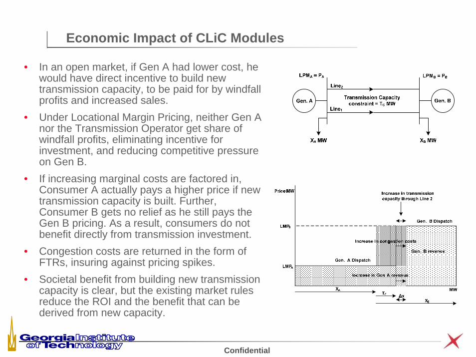
Economic Impact of CLiC Modules
• In an open market, if Gen A had lower cost, he would have direct incentive to build new transmission capacity, to be paid for by windfall profits and increased sales.
• Under Locational Margin Pricing, neither Gen A nor the Transmission Operator get share of windfall profits, eliminating incentive for investment, and reducing competitive pressure on Gen B.
• If increasing marginal costs are factored in, Consumer A actually pays a higher price if new transmission capacity is built. Further, Consumer B gets no relief as he still pays the Gen B pricing. As a result, consumers do not benefit directly from transmission investment.
• Congestion costs are returned in the form of FTRs, insuring against pricing spikes.
• Societal benefit from building new transmission capacity is clear, but the existing market rules reduce the ROI and the benefit that can be derived from new capacity.

Confidential
Smart Wires in a Smart Grid to Enable Sustainability
•It is proposed that the use of distributed solutions based on low-power power electronics can allow utilities to move towards dynamically controllable meshed grids, significantly enhancing grid reliability, capacity and utilization. This enables-
• Improved coordination between sources and loads
• Improved dynamic coordination between regions
• Reduction in dynamic capacity reserve for generators
•Can be applied at the transmission, sub-transmission and distribution levels.
•Can be layered onto the existing infrastructure as desired, and will not degrade the inherent reliability of the existing system.
•Makes the grid self-healing, automatically maintaining safe operating levels even in the face of contingencies.
•Can significantly enhance grid capacity and utilization without building new lines.
•Redundancy and ability to operate with local data provide high system reliability and availability•Provides solutions that are low-cost and can be implemented in a gradual manner
as resources and budgets permit