distributed by: national technical information … confcal wheel (top); ... taken to control launch...
TRANSCRIPT
AD-773 016
REPORT OF THE AD HOC WORKING GROUP ON INNOVATIVE MOBILITY CONCEPTS
Robert Ehrlich, et al
Stevens Institute of Technology Hoboken, New Jersey
October 1973
DISTRIBUTED BY:
National Technical Information Service U. S. DEPARTMENT OF COMMERCE 5285 Port Royal Road, Springfield Va. 22151
- ■ »_ .. .u__^. ■
™—-
UNCLASSIFIED SEC URI TV CLASSirir ATION OF THIS PAGE Wltn Dal« F.nlttKt) Ab 213 Qik
REPORT DOCUMENTATION PAGE ' REPORT MUMBCR
READ INSTRUCTIONS BEFORE COMPLETING FORM
2 OOVT ACCESSION NO 1 RECIPIENT'S CATALOG NUMBER
4 TITLE r»nd s.<M/f;»)
REPORT OF THE AD HOC WORKING GROUP ON INNOVATIVE MOBILITY CONCEPTS
S TYPE Of REPORT A PERIOD COVERED
FINAL
« PERrORMINO ORO. REPORT NUMIER
l CONTRACT OR GRANT NUMtCN^J 7 AuTHORftJ
I . Robert Ehrlich, et al
9 PERFORMING ORGANIZATION NAME AND ACORESS
DAVIDSON LABORATORY
10 PROGRAM ELEMENT. PROJECT, TASK AREA 4 WORK UNIT NUMBERS
II CONTROLLING OFFICE NAME ANU ADDRESS LTC Frank Cantwe11 Hq, Army Materiel Command Washington, D. C. 20315
12. REPORT DATE
October 1973 li. NUMBER Of PAGES
56 ♦ appendices H MONITORING AGENCY NAME A ADDRESSCI/<fm»ranl Inm Conlrolllnt OHIc») IS SECURITY CLASS, (ot Ihl» ttpotl)
Unclassified
IS*. OECUASSIPICATION/DOWNORADINO SCHEDULE
I« DISTRIBUTION STATEMENT 'of rMt l»«porl)
Approved for public release; distribution unlimited.
IT DISTRIBUTION STATEMENT Co/rh« abtiracf Miltrarf In Block 20, II dltltr»nl Item Rmporil
II SUPPLEMENTARY NOTES
If KEY WORDS fConllnu» on raver«* tld» II nocooaary and Idtntlly by klock numbtr)
.'. i r hi«,»-.! hy
NATIONAL TECHNICAL iNfOPMATION "sFRViCF
• : s Dep^.tmPrt ,- Co.
20 ABSTRACT iConilnu* on ravaraa Hd» II nacaaaary fd Idtmllr by block mmb»t)
Durlno 17-20 October 1972, a workshop to Identify, conceive and examine possibi-j concepts and approaches for materially Increasing the Army's ground mohillty was held In Durham, North Carolina, at the behest of thr Office of the Director of Defense Research and Engineering (00DRE) who charged the Army Materiel Command (AMC) with the responsibility of Implementing their request. AMC, In turn, assigned the task to a
AZ. DD I JAM 71 1473 EDITION OF I ROVtl IS OBSOLETE
s N (i in j-ni«. AAOI
I ftlCuKlTf CLAIIiriCATlOM O' TMII ^AOI (*hf* D»f Vn »rMj
.
UNCLASSIFIED wi T v CL*SSIf IC »'ION OF THIiP»GE't»>i»n PMa Enl»f<t)
Committee comprised of:
Or. I. Robert Ehrlich, Stevens Institute of Technology, Chairman LTC Franklin Cantwell, Headquarters, U.S. Army Materiel Command Mr. James Carr, Headquarters, U.S. Army Materiel Command Mr. Howard Dugoff, U.S. Army Tank-Automotive Command Mr. Adam Rula, U.S. ^rmy Engineer Waterways Experiment Station Mr. Clifford J. Nuttall, Jr., U.S. Army Engineer Waterways
Experiment Stat ion
It was the responsibility of this Steering Committee to plan and organize the sessions, to select and invite the attendees, to outline the content of the briefings, to obtain the briefers, to make all the administrative, housing and special arrangements, and to prepare this written report of the Workshop results.
The body of this report concentrates on the most significant Ideas suggested by the Workshop. To develop these particular Ideas further than was possible (or considered desirable) In the Workshop sessions, a two-day "idea improvement meeting" was held jn 22-23 May 1973, at St. Clalr, Michigan, The discussions which foJiow accordingly reflect the deliberations not only of the workshop attendees, but also of the participants at the St. Clair meeting. Administrative and organizational details, lists of attendees at both the Durham and St. Clair meetings, plus a complete listing of all ideas formulated, are included in the appendices for completeness.
Jl^ UNCLASSIFIED
SCHRITT Cu »»ii'iC*TiOH 0' TMit »«Ofmiwi Dai« tmtrtdi
. - Mil - I 11 ■ ■ — ■- ■ ■
ni H—WH
DAVIDSON LABORATORY Stevens Institute of Technology
Castle Point Station Hoboken, New Jersey 07030
Report SIT-OL-^-m'*
October 1973
REPORT OF THE AD HOC WORKING GROUP
ON INNOVATIVE MOBILITY CONCEPTS
Held at Durham, North Carolina
17-20 October 1972
and
St. C lair, Michigan 22-23 May 1973
by
I. Robert Ehrlich, Chairman Frank CantwelI James Carr
Howard J. Dugoff David Latson
Augustus Magistro Clifford J. üuttall, Jr.
Ronald Patek Adam A. Rula
Skrtches by Paul Spansky
L_. ; r-.u-
Approved by;
P/gfcjtßÖC ( I. Robert Ehrlich, Chairman
■■ii
R-I7I'*
TABLE OF CONTENTS
LIST OF FIGURES v
FORWARD vli
PREFACE «x
I. SUMMARY I
II. INTRODUCTION 3
Objective 3
Scope 3 Approach 3
Discussion **
III. RESULTS 7
A. Wheel Systems 7
B. Remote Controlled Vehicles \k
C. Driver Aids 15
D. Vehicle Form and Operational Concepts 20
E. Propulsion Concepts 36
F. Flotation and Traction Aids '♦I
G. External Mobility Aids Ml
H. Software Ideas 50
IV. CLOSURE 56
APPENDIX A - ORGANIZATIONAL DETAILS AND METHODOLOGY
APPENDIX B - PARTICIPANTS
APPENDIX C - INSTRUCTIONS FOR WORKSHOP
APPENDIX D - TEAM CHAIRMAN'S ORIENTATION
APPENDIX E - BRIEFING DOCUMENT
APPENDIX F - CHARACTERISTICS OF VARIOUS TERRAIN OBSTACLES
APPENDIX G - DETAILED TEAM IDEAS
APPENDIX H - MASTER AGENDA
ill
■ii—i
R-17^
LIST OF FIGURES
1 IF WHEELS WERE PROPLRLY DESIGNED, THEY COULD EASILY BE ATTACHED TO PROVIDE INCREASED FLOTATION AND TRACTION .... 8
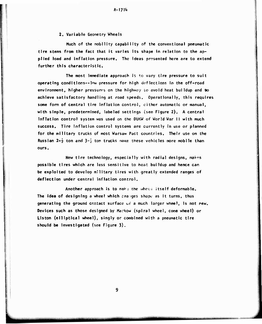
2 CENTRAL TIRF INFLATION SYSTEMS, WITH SIMPLE CONTROLS, WILL MATERIALLY IMPROVE THE MOBILITY OF WHEELED VEHICLES . . 10
3 EXAMPLES OF NON-CIRCULAR WHEELS. A CONfCAL WHEEL (TOP); AN ELLIPTICAL WHEfl (MIDDLE); A SpIPM WHEEL (BOTTOM). ... 11
k VEHICLES, CONlROLLtü FROM REMOTE. SEC,! LOCATIONS COULD PERFORM HAZARDOUS MISSIONS 13
5 A MARRIAGE OF THE GROUND VEHICLI WITH THE HELICOPTER WILL PROVIDE THE SOLDIER MOBILITY AFTf * il^CEMENT ON THE BATTLEFIELD 21
6 ARTICULATtD VEHICLES HAVE THE ADVANTAGE OF BOTH INCREASED MOBILITY ON THE GROUND AND INCREASED 7 "-ANSPORTAßl I.ITY IN THE AIR . . 22
7 THE ARTICULATtD TANK DtSCKIBEO IN THt TEXT OFFERS MANY OPERATIONAL ADVANTAGES 23
8 FOLDAüLL WHEEL" WOULD HE S10RED WHEN NOT NEEDED (TOP) BUT INFLATED FOR SOFT TERRAIN (BOTTOM), FOLOABLE WHEELS WOULD BE POWERED BY SMALL iDLFP, WHEELS 2k
9 TRUCKS, SPLC.FtLALLY DES IGNED TU Bl COIK'IED TOGETHER TO FORM TRAINS, PRIME UNIT (TOP) oCU'.; t^'JPLE TOOTHER PRIME UNIT OR TO CHEAPER SECü'JDAf<, l ... TO FORM TRAINS (LOWER TWO SKETCHES) . . . . 25
10 MODULAR COMPONENTS COULD EASILV ßt ASSEMBLED TO A VARIETY OF FRAMES TO FORM MANY DIFFERENT VEHICLE CONFIGURATIONS . . 2?
ii A POWERED, LIMP CHAIN, HANGING FROM AN AIR CUSHION VEHICLE COULD PROVIDE THE TPACTION NECESSARY TO GENERATE ADDI- TIONAL CONTROL AND --LOPE CLIMBING ABILITY 30
12 SPRING LOAOtO "PI. H CUTTERS" WOULD PROVIDE POSITIVE LATERAL COMIROL FOR CROSS-SLOPE OPERATION 31
13 DIVIDr.G THt MOTORS IN TWO AND ALLOWING FHEM TO STEER WOiir •'ROVIDF CRABBING ABILITY AND IMFR0V1 0 OPERATION ON ' ;M SURFACES 32
Preceding page blank
«■MMMH
•um^r^*^
R-l?^
List of Figures
\k AMONG THE HYBRID VEHICLES CONSIDERED WAS THAT OF HARRYING THE TRACK WITH AN AIR CUSHION TO NEGOTIATE SOFTER TERRAIN . . 3^
15 DIRECT USE OF THE COMBUSTION GASES TO INFLATE AND DEFLATE CIRCUMFERENTIALLY SEGMENTED TIRE CHAMBERS COULD ELIMINATE THE ENGINE-TRANSMISSION-DRIVE LINE SYSTEM 37
16 A LINEAR INDUCTION MOTOR COULD DRIVE A METAL IMPREGNATED BAND TRACK WITHOUT THE DRIVE-LINE AND GEAR SYSTEMS RE- QUIRED OF CONVENTIONAL TRACKS 39
17 IN A MANNER SIMILAR TO THAT SHOWN IN FIGURE 16, A LINEAR INDUCTION MOTOR CO LD DRIVE A STEEL-BELTED TIRE 39
18 TRACK SHOES, WHICH ARE DESIGNED TO YIELD TO IMPOSED STRESSES, RATHER THAN TO RESIST THEM, COULD MATERIALLY LIGHTEN TRACK DESIGN kl
19 A WATER JET, POWERED BY COMPRESSED AIR OR EXHAUST GASES, COULD PROVIDE SHORT-TERM AUXILIARY THRUST WHILE OVERCOMING OBSTACLES ^3
20 TO MAINTAIN ROPE CONTACT WITH THE CAPSTAN WHEN THE TRACKS BEGIN TO GRAB, THE CAPSTAN DIAMETER MUST BE GREATER THAN THE PITCH DIAMETER OF THE DRIVE SPROCKET hk
21 A PLASTIC BUBBLE WOULD ALLOW A FOOT SOLDIER TO 'VALK ON WATER." SUCH A DEVICE IS PRESENTLY IN USE FOR RECREATIONAL PURPOSES . Ud
22 VEHICLE-MOUNTED EXCAVATION DEVICES, SUCH AS A BACK-HOE OR FRONT-END LOADER, COULD BE USED TO REDUCE OBSTACLES AS WELL AS AID MOBILITY BY PROVIDING ADDITIONAL PUSHING FORCES. ... ^7
23 A HIGH-PRESSURE HOSE, MOUNTED ON AN AMPHIBIAN, COULD BE USED TO REDUCE RIVER BANKS TO A MANAGEABLE SLOPE **8
2k IN WORLD WAR I, TANKS CARRIED BUNDLES OF STICKS OR FENCING TO HELP BRIDGE TRENCHES. SIMILAR DEVICES COULD STILL BE UTILIZED 50
25 PROPERLY CONTOURED LAUNCH AND RECAPTURE RAMPS WOULD AID VEHICLES IN CROSSING SHORT GAPS (ABOVE). CARE MUST BE TAKEN TO CONTROL LAUNCH SPEED TO MATCH RAMP CONTOUR AND GAP DISTANCE TO AVOID CATASTROPHY (BELOW) 51
vi
MM •MMM mm
R-I7I1»
FORWARD
During 17-20 October 1972, a workshop to identify, conceive and
examine possible concepts and approaches for materially increasing the
Army's ground mobility was held in Durham, North Carolina, at the behest
of the Office of the Director of Defense Research and Engineering (0D0RE)
who charged the Army Materiel Command (AMC) with the responsibility of
implementing their request. AMC, in turn, assigned the task to a
committee comprised of:
Dr. I. Robert Ehrlich, Stevens Institute of Technology, Chairman
LTC Franklin Cantwell, Headquarters, U.S. Army Materiel Command
Mr, James Carr, Headquarters, U. S, Anny Materiel Command
Mr. Howard J. Dugoff, U. S. Army Tank-Automotive Command
Mr. Adam Rula, U. S. Army Engineer Waterways Experiment Station
Mr, Clifford J. Nuttall, Jr., U.S. Army Engineer Waterways Experiment Station
It was the responsibility of this Steering Committee to plan and
organize the sessions, to select and invite the attendees, to outline
the content of the briefings, to obtain the briefers, to make all the
administrative, housing and special •rrangements, and to prepare this
written report of the Workshop results.
The body of this report concentrates on the most significant Ideas
suggested by the Workshop. To develop these particular ideas further
than was possible (or considered desirable) in the Workshop sessions, a
two-day "idea Improvement meeting" was held on 22-23 May 1973, at
St. Clalr, Michigan. The discussions which fcliow accordingly reflect
the deliberations not only of the workshop attendees, but also of the
participants at the St. Glair meeting. Administrative and organizational
details, lists of attendees at both the Durham and St. Clair meetings,
plus a complete listing of all ideas formulated, are included in the
appendices for completeness.
vil
^iMMMH u^^^emmm
■ ' ' ■^■"
R'\7\k
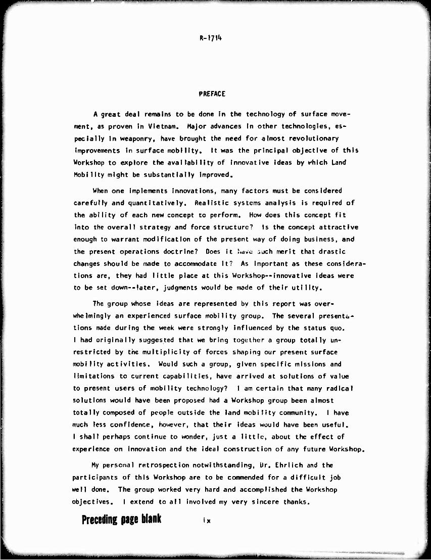
PREFACE
A great deal remains to be done in the technology of surface move-
ment, as proven in Vietnam. Major advances in other technologies, es-
pecially in weaponry, have brought the need for almost revolutionary
improvements in surface mobility. It was the principal objective of this
Workshop to explore the availability of innovative ideas by which Land
Mobility might be substantially improved.
When one implements innovations, many factors must be considered
carefully and quantitatively. Realistic systems analysis is required of
the ability of each new concept to perform. How does this concept fit
into the overall strategy and force structure? Is the concept attractive
enough to warrant modification of the present way of doing business, and
the present operations doctrine? Does it Iwve 3jch merit that drastic
changes should be made to accommodate it? As important as these considera-
tions are, they had little place at this Workshop—innovative ideas were
to be set down—later, judgments would be made of their utility.
The group whose ideas are represented by this report was over-
whelmingly an experienced surface mobility group. The several presenta-
tions made during the week were strongly influenced by the status quo.
I had originally suggested that we bring together a group totally un-
restricted by the multiplicity of forces shaping our present surface
mobility activities. Would such a group, given specific missions and
limitations to current capabilities, have arrived at solutions of value
to present users of mobility technology? I am certain that many radical
solutions would have been proposed had a Workshop group been almost
totally composed of people outside the land mobility community. I have
much less confidence, however, that their ideas would have been useful.
I shall perhaps continue to wonder, just a little, about the effect of
experience on innovation and the ideal construction of any future Workshop.
My personal retrospection notwithstanding, Dr. Ehrlich and the
participants of this Workshop are to be commended for a difficult job
well done. The group worked very hard and accomplished the Workshop
objectives. I extend to all involved my very sincere thanks.
Preceding page blank IX
lMa^MaBaia_MMaaMM
■ ■ ■
R-m1*
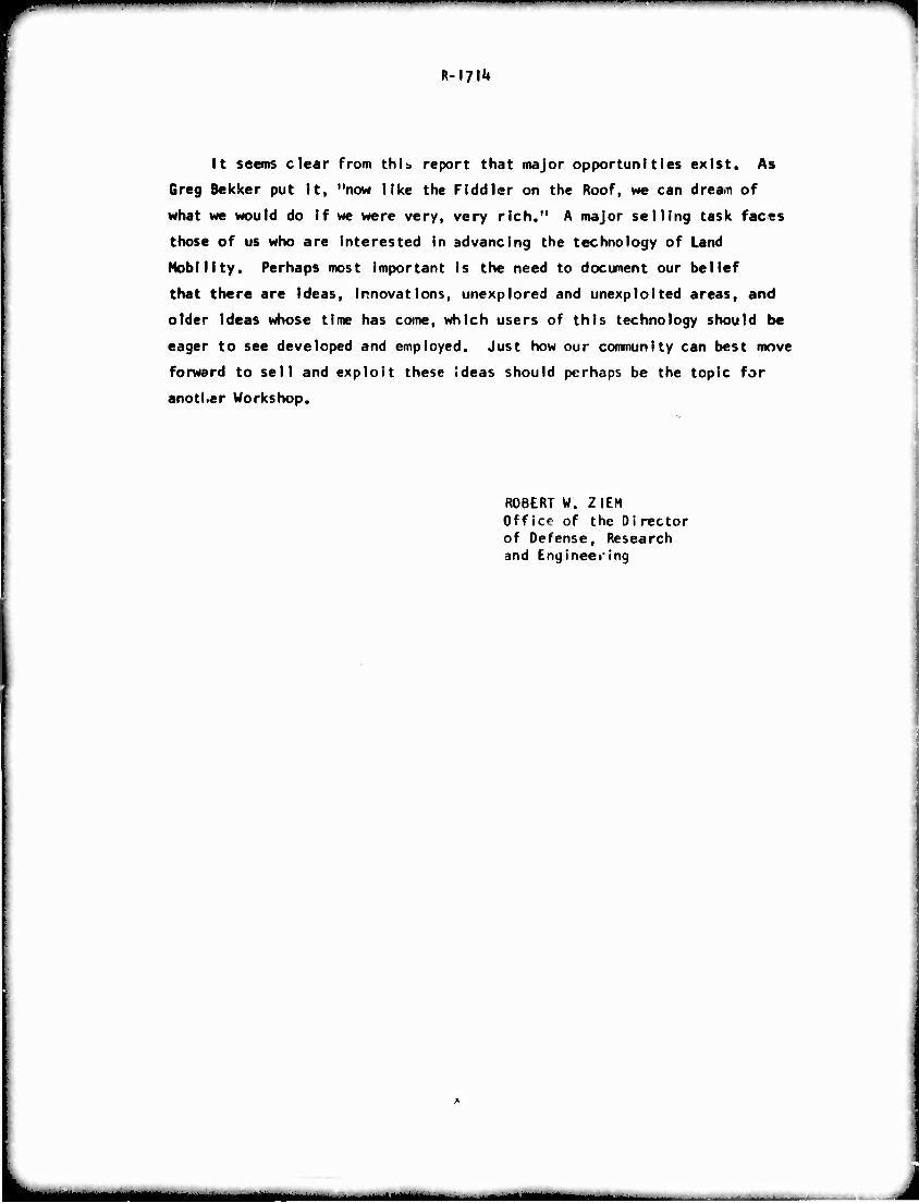
It seems clear from this report that major opportunities exist. As
Greg Bekker put it, "now like the Fiddler on the Roof, we can drea.n of
what we would do if we were very, very rich." A major selling task faces
those of us who are interested in advancing the technology of Land
Mobility. Perhaps most important is the need to document our belief
that there are Ideas, innovations, unexplored and unexploited areas, and
older ideas whose time has come, which users of this technology should be
eager to see developed and employed. Just how our community can best move
forward to sell and exploit these ideas should perhaps be the topic for
anotl.er Workshop.
ROBERT W. ZIEM Office of the Director of Defense, Research and Engineering
I ■M^IIBI
■'
R-l?!'*
I . SUMMARY
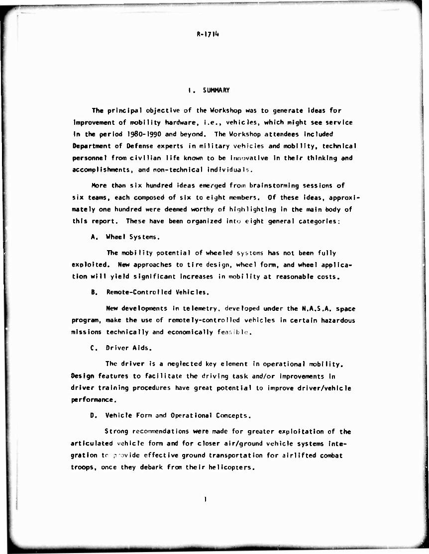
The principal objective of the Workshop was to generate ideas for
Improvement of mobility hardware, i.e., vehicles, which might see service
In the period 1980-1990 and beyond. The Workshop attendees included
Department of Defense experts in military vehicles and mobility, technical
personnel from civilian life known to be innovative In their thinking and
accomplishments, and non-technical individuals.
More than six hundred ideas emerged from brainstorming sessions of
six teams, each composed of six to eight members. Of these ideas, approxi-
mately one hundred were deemed worthy of hiqhlighting in the main body of
this report. These have been organized into eight general categories:
A. Wheel Systems.
The mobility potential of wheeled systems has not been fully
exoloited. New approaches to tire design, wheel form, and wheel applica-
tion will yield significant increases in mobility at reasonable costs.
B. Remote-Control led Vehicles.
New developments in telemetry, developed under the N.A.S.A. space
program, make the use of remotely-controlled vehicles in certain hazardous
missions technically and economically feasible,
C. Driver Aids.
The driver is a neglected key element in operational mobility.
Design features to facilitate the driving task and/or improvements in
driver training procedures have great potential to improve driver/vehicle
performance.
D. Vehicle Form and Operational Concepts.
Strong recoTimendations were made for greater exploitation of the
articulated vehicle form and for closer air/ground vehicle systems inte-
gration tr p'ovld« effective ground transportation for airlifted combat
troops, once they debark from their helicopters.
*t*—m
R-l?^
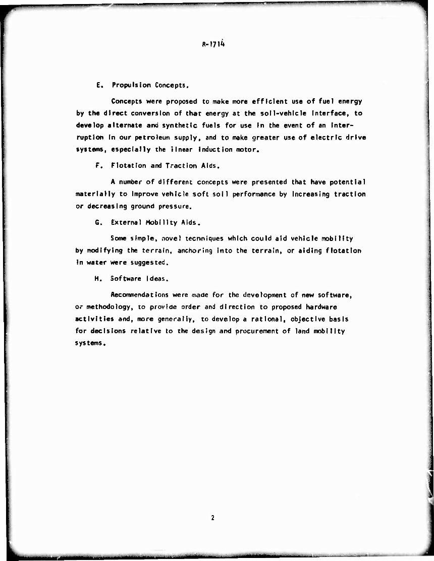
E. Propulsion Concepts.
Concepts were proposed to make more efficient use of fuel energy
by the direct conversion of that energy at the soil-vehicle interface, to
develop alternate and synthetic fuels for use in the event of an inter-
ruption in our petroleum supply, and to make greater use of electric drive
systems, especially the linear induction motor.
F. Flotation and Traction Aids.
A number of different concepts were presented that have potential
materially to Improve vehicle soft soil performance by increasing traction
or decreasing ground pressure.
G. Externe! Mobility Aids.
Some simple, novel tecnnlques which could aid vehicle mobility
by modifying the terrain, anchoring into the terrain, or aiding flotation
in water were suggested.
H. Software Ideas.
Recommendations were made for the development of new software,
or methodology, to provide order and direction to proposed hardware
activities and, more generally, to develop a rational, objective basis
for decisions relative to the design and procurement of land mobility
systems.
*■■ ^■M——I^II ■
R-17^
M. INTRODUCTION
Objective
The objectives of the Workshop were to review the state of ground
mobility technology and to identify possible concepts and approaches for
materially increasing the Army's ground mobility for the period 1980-1990
and beyond. The basic aim was to conceive Innovative hardware Ideas, not
to develop workable systems.
Scope
The hardware ideas were to relate to rhe movement of vehicles off
roads, cross country, and on unimproved ruads and trails. Only combat
(fighting) and tactical vehicle concepts were to be considered. Thus,
the following subjects, important in the overall aspects of mobility,
were excluded:
a. Aircraft
b. S h i ps
c. Amphibious vehicles
a, Tonta'nerization
e. Non-venicie iogistic system? (pipelines, fixed rails, monorails, conveyors, trutnw. ' .)
The scope of the efforr was limited to the identification of Ideas
which, when implemented, would ostensibly caur.e a direct and measurable
improvement in the performance of a combat or tactical vehicle In at
least one mobility situation. Considerations of feasibility, practi-
cability, cost, etc., or of implementation of the ideas was not permitted
to Inhibit their generation.
Approach
To achieve the objectives stated above, first the brainstorming
technique, v\r ch aims at generating a large number of unevaluated Ideas,
was utilized (see Appendix A) at a Workshop held in Durham, N. C. The
mm* - ■
R-I?!^
participants included DOD experts In the field of automotive vehicles,
personnel from civilian industry who were known to be technically inno-
vative In their thinking and accomplishments, and non-technical individuals
who, by their Innocence, would cause the workshop to think in new directions
(see Appendix B).
The most promising ideas generated In the Durham bra Ins terming sessions
were then developed further in an "Idea Improvement Session" held at St.
Clair, Michigan. Participants at this later session were limited to
military officers and D00 civilian engineers. The material which follows
represents the combined results of the two efforts.
Discussion
Mobility means many things to many people. Each person sees it In
the light of his own knowledge and experience. The term mobility Is defined
In AR 310-25 as: "A quality or capability of military forces which permits
them to move from place to place while retaining the ability to fulfill
their primary mission." The same document defines mobile warfare as:
'Varfare of movement In which the opposing sides seek to seize and hold
the initiative by use of maneuver, organization of fire and utilization
of terrain."
For the purposes of this workshop, a combat vehicle was defined as:
"A vehicle, with or without armor, designed for a specific fighting function."
A tactical vehicle was defined as: "A vehicle with military characteristics
designed primarily for use by forces in the field In direct connection with,
or support of, combat or tactical operat jns." The emphasis was on off-
road, cross-country operations.
The trend in recent years in the field of ground mobility has been
toward product improvement through a program of modification and moderni-
zation. This approach Is perhaps appropriate from a short-range viewpoint.
However, the fact that most of the Army's present fleet was built with
1950-60 state-of-the-art and will be 20 to 30 years old by 1980, suggests
that recent advances In technology must be exploited for new and improved
mobility systems that will provide the U.S. combat soldier of the future
with a tactical advantage.
mmm*
R-I7I^
There are many aspects of mobility. Early mobility research identi-
fied and studied in depth the soft soil problems. Many people, when they
think of a "highly mobile" vehicle still envision one slogging through
deep mud. Current understanding, however, recognizes many other important
aspecs of mobility. There Is the rough terrain problem which, while it
presents little potential for Immobilization, severely limits the speed
of the vehicle. There is also the problem of negotiating obstacles such
as fallen trees, ditches, banks, rocks and man-made Impediments.
Rivers place a severe restriction on ground vehicle operations. In
highly developed countries, most rivers are bridged at all essential and
convenient places to the extent that, in peace time, they are rarely
considered an Impediment to movement. However, in less developed nations
or in an unlimited war, we can expect but few bridges to exist, and those
that do exist to be of but limited capacity. Hence, the ability to cross
rivers is an important consideration in mobility. And river crossing is
more than just swimming; it Is entrance into the water, negotiating the
land/water interface, propulsion and control in the current, and exiting
at the far side.
Control has only recently been recognized as a mobility factor. A
vehicle which Is easy to control and has good handling qualities allows
Its operator and crew to function better, to TOVC more surely and to
maneuver well. Hence, control and the man/machine/environment constitute
another facet of mobility.
Armor protection becomes an aspect of mobility when it permits
selection of routes which would be denied to a thin-skinned vr'ticle.
Communications are also related to mobility, for they facilitate
coordinated movement and the exchange of information relative to route
conditions.
Last, but by no means least. Is RAM-0 (reliability, availability,
maintainability and durability), for a vehicle which is deadlined is
Just as immobile as one stuck In the mud.
R-l?!*»
Thus, there are many aspects of mobility which we have been able
to identify, in a given situation, we can overcome any of these by one
technique or another. We can go anywhere we please for a price. But to
deal with all possible mobility problems with a single vehicle would be
prohibitively expensive. Thus, the "mobilJty problem" is to go in as
many important areas as possible at a minimum complexity and cost. The
definitions of the two underlined words, "Important" and "minimum" become
the center of focus. How do we define "important" and what can we afford?
The basic approach in the Workshop was to develop totally new ideas
or approaches towards improved mobility. However, since new ideas are
not easily generated, a look was taken at new applications of old ideas,
at old ideas in the light of newly developed or soon to be expected techno-
logy, and at old ideas that may not have been fully tested or evaluated.
m*mm
R-m'*
III. RESULTS
The ideas for the improvement of Army ground mobility generated in
brains terming sessions numbered more than six hundred, an average of more
than one hundred per team. (There were, of course, many cases of dupli-
cation or close similarity.) All ideas generated by each of the six teams
are contained in the respective sections of Appendix G.
Following the brainstorming sessions, each team was asked to review
Its own ideas, to select and to amplify the "best" ten. Each team selected
its own criteria for evaluation. Some teams, being more enthusiastic (or
less disciplined) selected more than ten. Hence, from the six teams,
approximately one hundred ideas finally emerged.
In general, the ideas reflected attempts to get more out of the wheel,
to get more out of the driver, to supplement vehicle capabilities and to
modify the terrain environment. Many ideas also reflected complete systems
concepts and methodology. For convenience, these ideas were subdivided
Into eight, not always mutually exclusive categories.
A. Wheel Systems
There was a strong feeling among participants that the mobility
potential inherent in the wheel form has not been fully exploited. New
approaches to tire design, wheel form, and wheel application will yield
significant increases in mobility at reasonable costs.
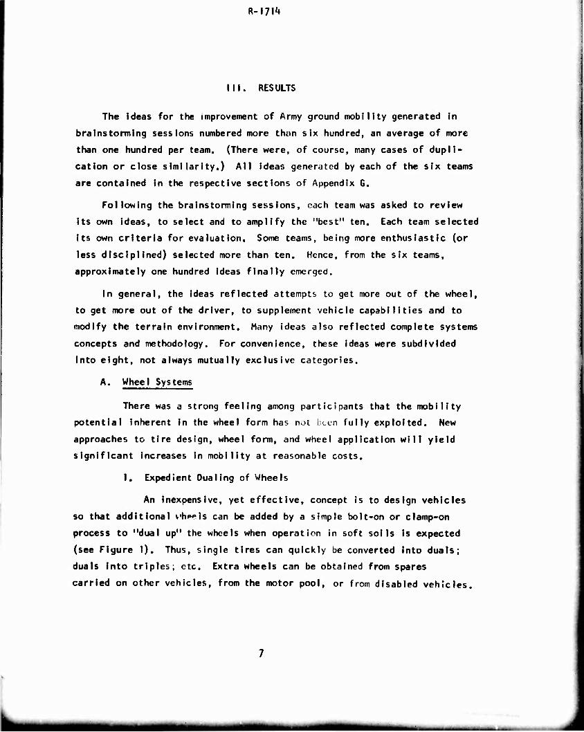
I. Expedient Qua ling of Wheels
An inexpensive, yet effective, concept is to design vehicles
so that additional vh^els can be added by a simple bolt-on or clamp-on
process to "dual up" the wheels when operation in soft soils is expected
(see Figure I). Thus, single tires can quickly be converted into duals;
duals into triples; etc. Extra wheels can be obtained from spares
carried on other vehicles, from the motor pool, or from disabled vehicles.
mmgmmm -
R-I7I1»
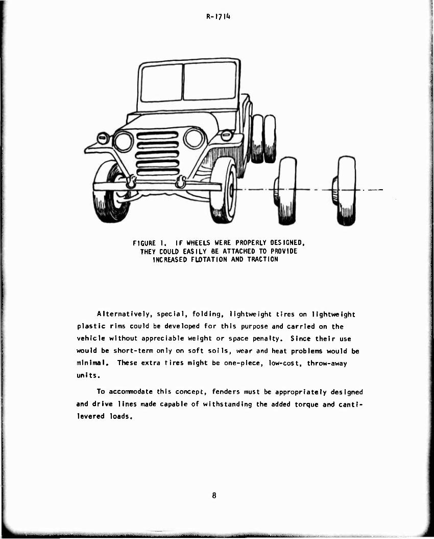
FIGURE I. IF WHEELS WERE PROPERLY DESIGNED, THEY COULD EASILY BE ATTACHED TO PROVIDE
INCREASED FLOTATION AND TRACTION
Alternatively, special, folding, lightweight tires on lightweight
plastic rims could be developed for this purpose and carried on the
vehicle without appreciable weight or space penalty. Since their use
would be short-term only on soft soils, wear and heat problems would be
minimal. These extra tires might be one-piece, low-cost, throw-away
units.
To accommodate this concept, fenders must be appropriately designed
and drive lines made capable of withstanding the added torque and canti-
levered loads.
—
R-l?!^
2. Variable Geometry Wheels
Much of the mobility capability of the conventional pneumatic
tire stems from the fact that it varies its shape in relation to the ap-
plied load and inflation pressure. The ideas presented here are to extend
further this characteristic.
The most immediate approach is to vary tire pressure to suit
operating conditIons--low pressure for high deflections in the off-road
environment, higher pressures on the highway io avoid heat buildup and to
achieve satisfactory handling at road speeds. Operationally, this requires
some form of central tire inflation control, either automatic or manual,
with simple, predetermined, labeled settings (see Figure 2). A central
Inflation control system was used on the OUKW of World War II with much
success. Tire inflation control systems are currently in use or planned
for the military trucks of most Warsaw Pact countries. Their use on the
Russian 2-5 ton and 3-] ton trucks maKe these vehicles more mobile than
ours.
New tire technology, especially with radial designs, mal^rs
possible tires which are less sensitive to heat buildup and hence can
be exploited to develop military tires with greatly extended ranges of
deflection under central inflation control.
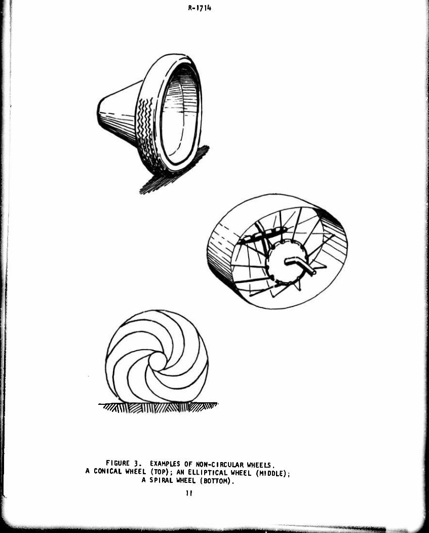
Another approach is to ma^ ,• the whroi itself deformable.
The idea of designing a wheel which cna iges shap«. as it turns, thus
generating the ground contact surface or a much larger wheel, is not pew.
Devices such as those designed by Ma.'kow (spiral wheel, cone wheel) or
Listen (elliptical wheel), singly or combined with a pneumatic tire
should be Investigated (see Figure 3).
r- -■- ■-
R-I?!1»
«>
UJ a. H r w> — . >- 10
z -J o o < — I- oe S :5ui> u. < o z r UJ
.^5
2 o >
Ul Z -I o o —
o oo • UJ X.
CM -I a. ui X. 10
5
10
R-m1»
"^ W^
FIGURE 3. EXAMPLES OF NON-CIRCULAR WHEELS. A CONICAL WHEEL (TOP); AN ELLIPTICAL WHEEL (MIDDLE);
A SPIRAL WHEEL (BOTTOM).
II
R-I7I1*
3. The Tire as a Suspension Element
The pneumatic tire Is Itself a spring. There are obvious
advantages in using the tire as the principle suspension element. One
approach Is to configure the wheel itself as a spring and damper system.
By varying pressure, the spring rate can be changed In accordance with
load and terrain. Conventional tires, however, have neither sufficient
damping nor deflection properties to maximize this possibility. By placing
chambers within the tire to restrict Internal air flow, greater damping
characteristics could be obtained. Tire pressures can be varied to detune
vehicle response to input vibrations. Here again, central inflation
control would be a key element.
*♦. Damage-Proof Tires
Pneumatic tires provide excellent ride and control properties.
However, they are highly susceptible to damage from enemy fire and off-
road hazards. Army vehicles, especially those designed for combat missions,
badly need a damage-proof tire. Present foam-filled concepts have not
proved successful because of heat buildup due to the hysteresis from
flexing and the excellent insulating propertips of the foam. A foam which
has low hysteresis properties and/or is a good conductor of heat would
hold up better. Flexible supporting structures oti T than pneumatic
chambers should also be Investigated.
Run-fiat capabilities should be extended. Tires which fold
within the rim, hence are still marginally usable, have promise. So do
dual concentric chambers.
A cartridge which Injects a foam or ga., to seal a break and
reinflate the tire is also { possibility. Such a system could be manually
operated or triggered frjm 'he change in air pressure or temperature that
would occur at or near failure.
12
If _^
R-I?!^
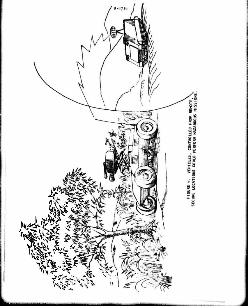
B. Remote Controlled Vehicles
Many of the teams suggested roles in which remote control could
be exploited to aid mobility. The applications proposed included combat,
reconnaissance and traction aid. Remotely controlled vehicles (RCV's) can
isolate the soldier from potential danger when operating in radioactive
areas, probing roads and areas suspected of mines and booby traps, de-
signating targets and aiding or retrieving damaged combat vehicles. RCV's
can also be put through maneuvers that man cannot tolerate. Taking
personnel from such vehicles reduces space, armor and suspension require-
ments and hence permits reduction in size, weight and automotive complexity,
Direct mobility applications suggested were:
o A small, highly mobile, scout or lead vehicle, radio-
controlled by a human operator in a following vehicle
to send back TV or sensor readings to following personnel.
o Remotely controlled trailmarker or pioneer vehicles
(see Section D5).
o Remotely controlled daughter unit of a two-element
combat vehicle (see Section 02).
o Remote controls in the local sense would allow the crew
of a manned combat vehicle to be grouped In a single,
compact, highly protected region of the vehicle, leaving
the less vulnerable components exposed or only lightly
protected. Protecting only vital components would greatly
lighten the armor required.
With the great recent advances in integrated circuitry, more rugged
television cameras and transmitters, and more sophisticated control cir-
cuitry and techniques, the electronic componentry for RCV's can be made
relatively inexpensive and reliable. Combined with changes in vehicle
form, this approach opens the way to relatively Inexpensive, mass-
produced vehicles. In the combat role, low cost will permit greater
expendabiIity and greater numbers, which could provide battlefield
superiority. For combat, as for other applications, the effective ex-
}U
R-I7H»
ploitatlon of RCV's will obviously require the development of radically
new tactics and doctrine.
The principal engineering difficulties attendant to the development
of RCV's for practical military application are those associated with
the communications system. Jamming, signatures and enemy Interception
nf data are all potential problems. The most critical difficulty, however.
Is the transmission and display of the massive quantity of feedback in-
formation required for remote operation in the cross-country environment.
Because of the complexity of that environment, the operator of an off-
road RCV will almost certainly require a continuous, panoramic visual
display, with resolution at least equivalent to that provided by commer-
cial television. Research is needed to establish the precise nature of
communication requirements for various potential RCV missions and the
associated implications for system development.
In another concept, remote control, coupled by force and position
feedback, appears attractive in the development of man amplifiers and
walking machines. At present, these concepts are workable, but the
complexity and costs make for impractical systems. An Important area
for development, therefore. Is mechanisms and techniques which make
feedback control systems practical for land vehicle application.
C. Driver Aids
The driver was Identified as a neglected key element in opera-
tional mobility. To get more out of the driver, we must provide him
with better training and improve his operating environment and his
interfaces with the vehicle.
I, Driver Training
The differences in vehicle performance achieved by trained
and untrained drivers are vast. Current Army training practices do not
appear to be fully effective in training the driver to exploit the total
performance potential of bis vehicle under extreme conditions of use.
Providing such training in a real vehicle under realistic field stress
conditions is both expensive and dangerous, it is suggested that simulator
15
R-I?!^
devices, similar to those currently !n wide use for pilot training, could
also be profitably employed for training off-road vehicle drivers. There
is a we 11-dove loped related technology base deriving from the activities
of workers in the highway safety field who have developed a variety of
road simulators for both research and training purposes.
The major impediment, co the development and practical use of
off-road driving simulators appears to be the difficulty of providing
realistic simulations of visual displays and other necessary driving cues
at reasonable cost. Research appears needed to establish just what level
of realism is necessary to make a simulation useful for training purposes.
Even with extensive use of simulators, complete training
requires a certain degree of behind-the-wheei field experience. To make
such experience most effective, it should be obtained under operating
conditions which tax the vehicle to Its limits. Research consideration
must be given to the design of suitable training courses and associated
programs of instruction.
2, Shock and Vibration Alleviation
The major driver environmental factors detrimental to mobility
are those associated with shock and vibration. A number of recommendations
were made for the alleviation of these factors.
o Use of an active suspension that senses the terrain ahead
and displaces suspension elements in anticipation of
oncoming irregularities. The sensor could be an on-board
laser, sonar, etc., or a mechanical device In a lead unit,
perhaps remotely controlled.
o Use of a suspension system which automatically varies its
spring rates, damping rates and static attitude in response
to vehicle load and terrain inputs. The inherent variable
attitude feature would reduce the elevation requirements
of a vehicle-mounted weapon.
16
R-I7I1*
o Use of crew Isolation to reduce requirements for suspend-
ing the entire vehicle. This concept could be implemented
in a small way with an improved (suspended) crew seat.
The full concept envisions the crew to be concentrated
In a separately suspended compartment. Suspension of this
compartment would probably have to be active, and controls
remote.
o Use of specially designed suits which would increase crew
tolerance to shock and vibration. Conceptually, this
suit could resemble a "G" suit such as used by airmen, or
it could be a special harness or sling system.
3. Driving Cue Augmentation
Providing the driver with more and better information on the
status of his vehicle in relation to the operational environment promises
to Improve his effectiveness materially. Systems that appear to have
potential are:
o Television, mirrors or fiber optics to extend the driver's
field of vision or to allow him to be placed at a more
convenient or stable location. These systems could in-
corporate vision intenslfiers for operation under reduced
visibility.
o Navigation or guidance systems, either on-board (inertial)
or remote (LORAN, etc.) to aid the driver and crew to
operate In unfamiliar terrain. Such systems would lessen
the need for detailed maps and movement control and would
be especially valuable during night operations. In snow
or heavy fc-j, or in terrain such as mountains, forests
and deserts, where there are few recognizable features
for guidance.
17
R-m'»
o Remote terrain sensing and analyzing systems to produce
mobility maps to a'd in route selection, mission operations
and driver control. Such systems could be operated from
aircraft or satellites.
o A system which detects the water content of a soil would
be extremely useful, sInce,coupled with other terrain
characteristics (vegetation, soil, type, etc.), this know-
ledge would give strong clues regarding soil strength.
If day-to-day records of soil moisture condition were
maintained, optimum times for operation through an area
could be forecast.
o Tactile feedback to the driver of the traction conditions
at the soil-vehicle interface. Knowing how much traction
is available to each set of running gear would enable the
driver to proportion torque application in an optimum
manner.
k. Human Engineering
There are human engineering improvements that can enhance
vehicle mobility by facilitating the mechanics of dr'ving and by alleviat-
ing psychological stresses on the driver. Among the former are more
utilization of power assists, more control automation, simplified control
settings, greater adjustability of controls to match driver physique, and,
perhaps, greater use of audio, tactile and/or odor signals to communicate
appropriate information.
The importance of driver confidence is not as well recognized.
It has been demonstrated that the driver of an H151 truck will go signi-
ficantly faster cross-country if given the added sense of security provided
by a roll bar. This experience suggests the desirability of such other
features as:
o Easily released and discarded lap and shoulder safety belts.
o Rapid ejection systems for crews of combat vehicles.
18
■MMHHMMH
R-l?!*»
o Simple, secure distress signal systems to Inform friendly
forces of Immobilization, Injury,loss of way and other
factors such as enemy activity, etc.
5. Driving Task Sharing
Rational division of the driving function between two indivi-
duals would double the sensing, analysis and manipulation capabilities
available to perform the difficult task of Jriving at high speed cross-
country. By such dual control, one operator would directly set and keep
the general course and route selection.; while the second driver would
concern himself solely with the terrain immediately in front of the vehicle,
This scheme exists in rudimentary form during buttoned-up tank operations
and In more sophisticated form with a horse and rider.
6. Convoy Control
The Army's logistic tail is long and complex. At one point
or another, supplies are generally moved In convoys, the mobility of which
is determined as much by convoy control limitations as by individual
vehicle performance. Principal operational problems are in the maintenance
of convoy Integrity and reliable convoy navigation under the stress of
maximizing convoy speed in the general confusion of the combat and near-
combat environment. Operations at night and in other situations,in which
effective visibility is severely reduced,compound the basic problem.
One broad approach to solving convoy problems is to reduce
dependence on convoys, per se, through the reduction of forward area line
items, full exploitation of combat loads (by trucks, containers), improved
load control and identification, etc. Non-convoy distribution could be
implemented by the development of doctrine and hardware to apply traffic
management techniques and rapid transit technology in the field to control
and direct individual vehicles. Networks of rapidly deployable automated
traffic sensors and directors could be developed which (using suitable
transponders) could guide individual trucks on optimum routes under field
computer control.
19
i . m
R-I7IU
Possibilities to improve the timely throughput of goods and
trooos using convoys range from relatively simple on-board devices, to
help drivers maintain Intervehicle spacings appropriate to convoy speeds
and road conditions, through to the development of fully automated systems
for convoy dispatch, navigation and operation which might also signifi-
cantly reduce convoy manpower and even convoy vulnerability.
There has been little significant v.ork connected with techno-
logic possibilities to improve convoy effectiveness since the early \3S0's
when possibilities to hard-couple tactical trucks for convoy use were briefly
addressed. The bulk of he possibilities lie within the state-of-the-art
of various technologies. The major technical problem is determination of
credible effectiveness benefits against which to compare inevitable costs
associated with various possible degrees of system sophisticated at each
major echelon in the TOE distribution system.
D. Vehicle Form and Operational Concepts
The basic form of a vehicle dictates its mobility envelope. A
number of unconventional vehicular shapes and forms were suggested. Some
were totally new concepts; some were old concepts which warrant re-examination
and further development; and some were hybrid combinations of existing forms.
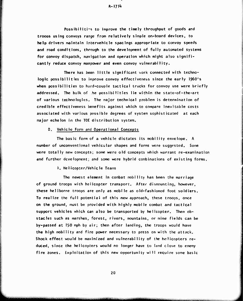
1. Helicopter/Vehicle Teams
The newest element in combat mobility has been the marriage
of ground troops with helicopter transport. After dismounting, however,
these heliborne troops are only as mobile as old-fashioned foot soldiers.
To realize the full potential of this new approach, these troops, once
on the ground, must be provided with highly mobile combat and tactical
support vehicles which can also be transported by helicopter. Then ob-
stacles such as marshes, forest, rivers, mountains, or mine fields can be
by-passed at 150 mph by air; then after landing, the troops would have
the high mobility and fire power necessary to press on with the attack.
Shock effect would be maximized and vulnerability of the helicopters re-
duced, since the helicopters would no longer have to land close to enemy
fire zones. Exploitation of this new opportunity will require some basic
20
a^a__^aaakaaB^MaaMaaa^aMMMH
R-l/l1»
changes In the morphology of both our ground vehicles and our helicopters
(see Figure 5). Some of the unconventional vehicle forms suggested below
are responsive to these new demands.
^TH^
FIGURE 5. A MARRIAGE OF THE GROUND VEHICLE WITH THE HELICOPTER WILL PROVIDE THE SOLDIER MOBILITY AFTER PLACEMENT ON THE BATTLEFIELD.
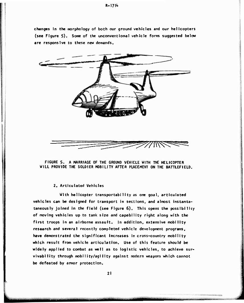
2. Articulated Vehicles
With helicopter transportabiIity as one goal, articulated
vehicles can be designed for transport In sections, and almost instanta-
taneously joined in the field (see Figure 6). This opens the possibility
of moving vehicles up to tank size and capability right along with the
first troops in an airborne assault. In addition, extensive mobility
research and several recently completed vehicle development programs,
have demonstrated the significant increases in cross-country mobility
which result from vehicle articulation. Use of this feature should be
widely applied to combat as well as to logistic vehicles, to achieve fur-
vivability through mobility/agility against modern weapons which cannot
be defeated by armor protection.
21
riMH tfMMMi —
R-l?!1!
-"=0232
QfTrm IQ*L
FIGURE 6. ARTICULATED VEHICLES HAVE THE ADVANTAGE OF BOTH INCREASED MOBILITY ON THE GROUND AND INCREASED TRANSPORTABILITY
IN THE AIR.
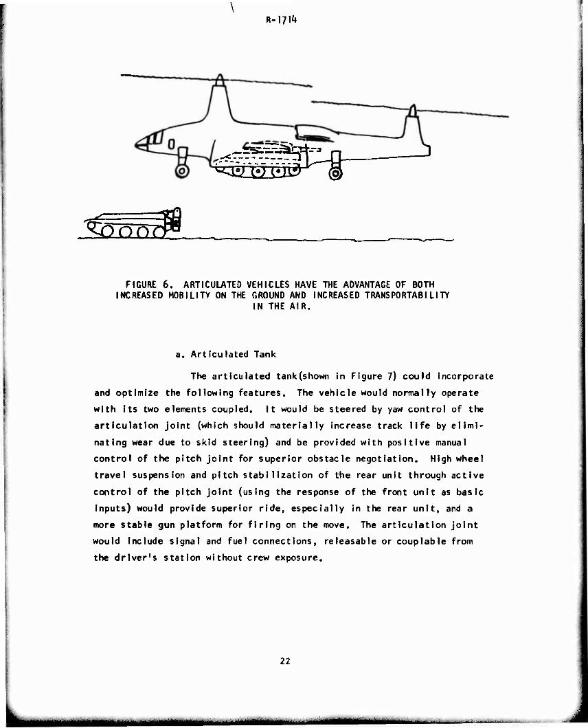
a. Articulated Tank
The articulated tank(shown in Figure 7) could incorporate
and optimize the following features. The vehicle would normally operate
with its two elements coupled. It would be steered by yaw control of the
articulation joint (which should materially increase track life by elimi-
nating wear due to skid steering) and be provided with positive manual
control of the pitch joint for superior obstacle negotiation. High wheel
travel suspension and pitch stabilization of the rear unit through active
control of the pitch joint (using the response of the front unit as basic
inputs) would provide superior ride, especially in the rear unit, and a
more stable gun platform for firing on the move. The articulation joint
would include signal and fuel connections, releasable or couplable from
the driver's station without crew exposure.
22
tamtam mam
R-iyi1»
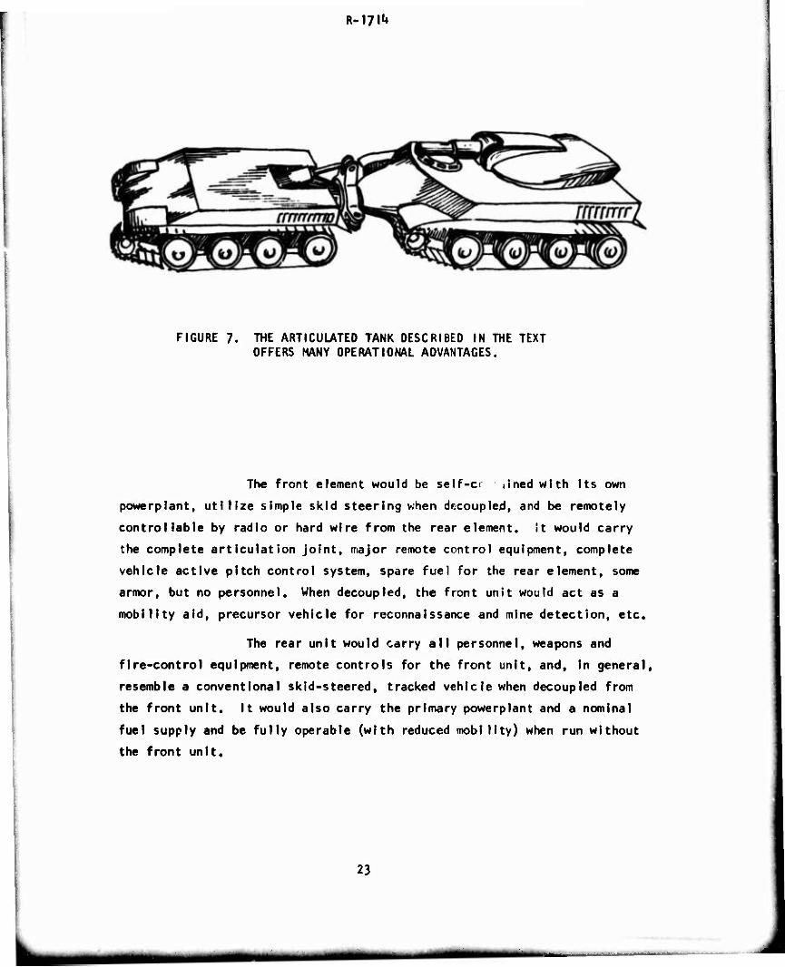
FIGURE 7. THE ARTICULATED TANK DESCRIBED IN THE TEXT OFFERS MANY OPERATIONAL ADVANTAGES.
The front element would be self-c« lined with Its own
powerplant, utilize simple skid steering when decoupled, and be remotely
controllable by radio or hard wire from the rear element. It would carry
the complete articulation joint, major remote control equipment, complete
vehicle active pitch control system, spare fuel for the rear element, some
armor, but no personnel. When decoupled, the front unit would act as a
mobility aid, precursor vehicle for reconnaissance and mine detection, etc.
The rear unit would carry all personnel, weapons and
fire-control equipment, remote controls for the front unit, and, In general,
resemble a conventional skid-steered, tracked vehicle when decoupled from
the front unit. It would also carry the primary powerplant and a nominal
fuel supply and be fully operable (with reduced mobility) when run without
the front unit.
23
mmm
R-1711»
The front unit, being less complex than the rear, would
be considered S'Mii-expendable. Thus, it could be utilized for mine clear-
ing operations, reconnaissance (perhaps mounted with TV) and as a protective
front shield from enemy fire. On the other hand, it would be an aid to
the rear unit when negotiating obstacles and, in case of rear unit engine
failure, would provide emergency get-home capability.
b. Articulated Wheeled Vehicles
A number of concepts for articulated wheeled vehicles
were also suggested.
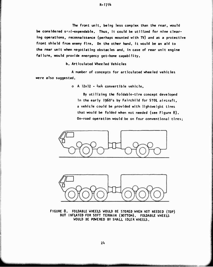
o A 12x12 - 'txk convertible vehicle.
By utilizing the foldabie-tire concept developed
in the early I960's by Fairchild for STOL aircraft,
a vehicle could be provided with lightweight tires
that would be folded when not needed (see Figure 8).
On-road operation would be on four conventional tires;
FIGURE 8. FOLDABLE WHEELS WOULD BE STORED WHEN NOT NEEDED (TOP) BUT INFLATED FOR SOFT TERRAIN (BOTTOM). FOLDABLE WHEELS
WOULD BE POWERED BY SMALL IDLER WHEELS.
m
mm
R-171^
for off-road situations that require it, the additional
tires would be inflated to provide additional flota-
tion and traction. These extra tires would be powered,
either by a conventional drive line or, more economi-
cally, by smaller idler tires which would provide
friction drive between the regular drive wheels and
the foldable tires. Frame-articulated steering would
be one requisite to the practicability of this concept;
another would be centra) inflation control of individual
tires.
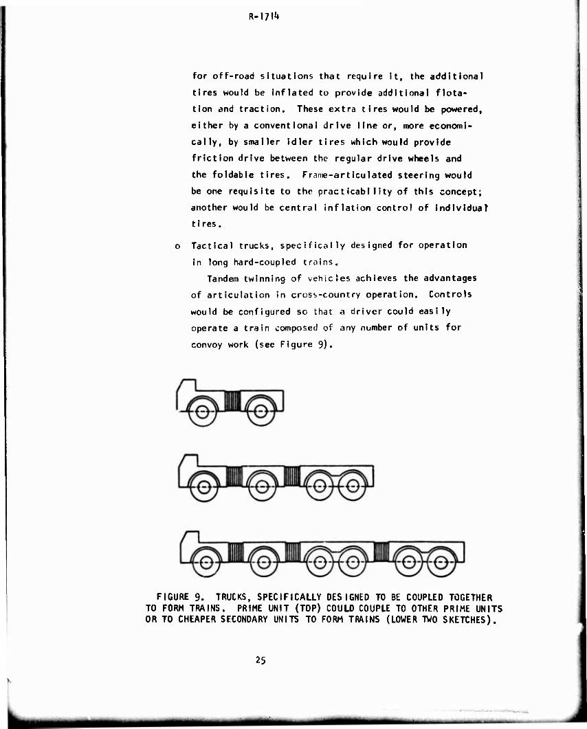
o Tactical trucks, specifically designed for operation
in long hard-coupled trains.
Tandem twinning of vehicles achieves the advantages
of articulation in crosb-country operation. Controls
would be configured so that a driver could easily
operate a train composed of any number of units for
convoy work (see Figure 9).
FIGURE 9. TRUCKS, SPECIFICALLY DESIGNED TO BE COUPLED TOGETHER TO FORM TRAINS. PRIME UNIT (TOP) COULD COUPLE TO OTHER PRIME UNITS OR TO CHEAPER SECONDARY UNITS TO FORM TRAINS (LOWER TV/O SKETCHES).
25
■■
R-I?!^
o Motor cycle trains.
The USDA Forest Service has developed a gyro-
stablllzed trail vehicle which runs on a single line
of tires. Using this stabilization system, clever
geometry and perhaps supplemer.tal stabilization from
small thrusters, a practical over- the-traiI train
under the control of one man might be developed.
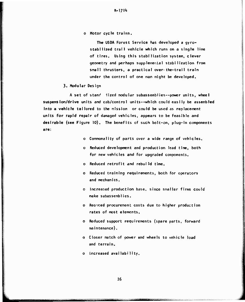
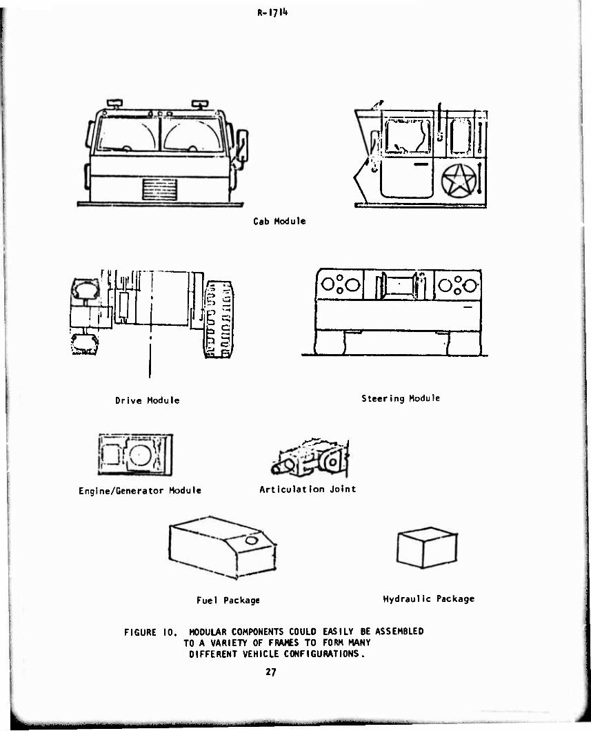
3. Modular Des ign
A set of stand ilzed modular subassemblies—power units, wheel
suspension/drive units and cab/control units—which could easily be assembled
into a vehicle tailored to the mission or could be used as replacement
units for rapid repair of damaged vehicles, appears to be feasible and
desirable (see Figure 10). The benefits of such bolt-on, plug-in components
are:
o Commonality of parts over a wide range of vehicles.
o Reduced development and production lead time, both
for new vehicles and for upgraded components.
o Reduced retrofit and rebuild time.
o Reduced training requirements, both for operators
and mechanics.
o Increased production base, since smaller firms could
make subassemblies.
o Recriced procurement costs due to higher production
rates of most elements.
o Reduced support requirements (spare parts, forward
maintenance).
o Closer match of power and wheels to vehicle load
and terrain.
o Increased availability.
26
R-I7I1»
Cab Module
Dl It [
'te!
aL 111
ta-B/
Drive Module
olo\ itJiloSo
E 3 Steering Module
Engine/Generator Module Articulat ion Joint
Fuel Package Hydraulic Package
FIGURE 10. MODULAR COMPONENTS COULD EASILY BE ASSEMBLED TO A VARIETY OF FRAMES TO FORM MANY
DIFFERENT VEHICLE CONFIGURATIONS.
27
I ■ i "" ■■-■■- 1
R-l/l4*
Addition of a track/sus pens ion/drive module would in-
crease the flexibility of the modular design concept. Further flexibility
could be achieved by designing a wheel/suspcnsion/drive module specifically
for expedient use in supplying power to the wheels of trailers in the
tactical support fleet.
The development of modern electric drive systems of
suitable capability or of more advanced mechanical in-wheel drive systems
appears to be essential to achieve modular design. Such developments
would make possible the elimination of the mechanical drive line, thus
freeing overall vehicle aesign to attain simplified suspensions, more
effective configurations, and highly durable, reliable, true all-wheel
drive articulated wheeled vehicles which can be readily converred to
tracked configurations.
Some specific technical questions which warrant immedi-
ate attention prerequisite to Implementation of a modular-base fleet plan
include the following:
o A parametric fleet üefinition that includes deter-
mining the optimum size and number of modules, the
associated levels of performance required, and the
identification of elements now available and those
which require new R&O efforts to achieve.
o Special emphasis on de fin Ing new drive system require-
ments (electric, hydraulic, f?tc.), within and outside
the current state-of-the-art in related technologies,
which are implicit in the multiple module concept.
o The space and weight limitations and penalties within
the modular family.
o The controls problem of multi-engines in the larger
vehicles.
o The feasibility of throwaway modules or, at minimum,
readily replaceable modules to reduce the maintaln-
abi11ty burden.
28
R-l?!1*
o The many problems of interfacing standard components
and modules within the range of vehicle sizes con-
sidered.
o The cost effectiveness of the concept in its optimum
configuration for the life of the fleet, reflecting
upgrading of fielded modules and assurance of neces-
sary RAM-D.
k. Air Cushion Concepts
The Air Cushion Vehicle (ACV) promises uniquely fast (30-120 mph)
transportation over unimproved terrain including soft soil, swamps and com-
binations of land and water. This capability could give surprise, quick
reaction and near all-weather operation, with minimum environmental damage.
The promises of the ACV have not yet been fully realized, principally due
to certain operational problems. Some of the problems and suggested solu-
tions are:
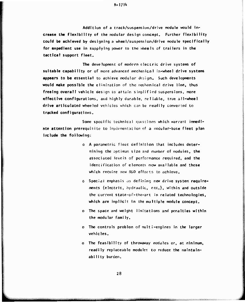
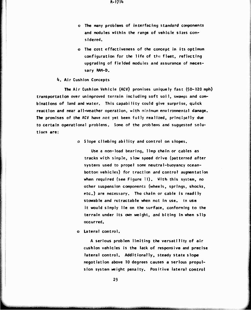
o Slope climbing ability and control on slopes.
Use a non-load bearing, limp chain or cables as
tracks with simple, slow speed drive (patterned after
systems used to propel some neutral-buoyancy ocean-
bottom vehicles) for traction and control augmentation
when required (see Figure II). With this system, no
other suspension components (wheels, springs, shocks,
etc.) are necessary. The chain or cable Is readily
stowable and retractable when not in use. In use
it would simply lie on the surface, conforming to the
terrain under its own weight, and biting in when slip
occurred.
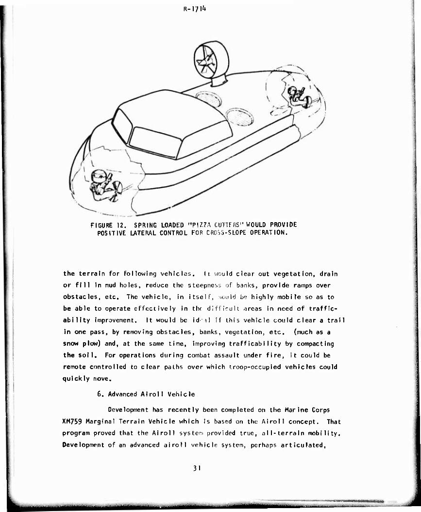
o Lateral control.
A serious problem limiting the versatility of air
cushion vehicles is the lack of responsive and precise
lateral control. Additionally, steady state slope
negotiation above 10 degrees causes a serious propul-
sion system weight penalty. Positive lateral control
29
MMta
R-m1*
FIGURE II. A POWERED, LIMP CHAIN, HANGING FROM AN AIR CUSHION VEHICLE COULD PROVIDE THE TRACTION NECESSARY TO GENERATE ADDITIONAL CONTROL
AND SLOPE CLIMBING ABILITY.
would permit operation across slopes and, by climbing
on the bias, permit negotiation of steeper slopes. A
thin rudder-like vane or disk, one Forward and one
steerable aft and both spring loaded against the surface,
could be utilized to provide needed high lateral resis-
tance with minimal longitudinal drag (see Figure 12).
Penetration into the surface would be caused by both
a responsive suspension system and vibration of the
contacting element; soil penetration would be inversely
proportional to soil strength, hence only the penetra-
tion neceujary to achieve the desired lateral forces
would result.
5. Trallmaker (or Pioneer) Vehicle
Envisioned here is a high performance engineer vehicle speci-
fically designed to support other vehicles with more conventional military
functions or missions. The vehicle would be outfitted with on-board mobility
aids not feasible in any other type of vehicle (pushers, compactors, winches,
dozer blades, scoops, cutters, etc.) so that it ould clear a path and improve
30
R-m^
FIGURE 12. SPRING LOADED "PIZZA CUTTERS" WOULD PROVIDE POSITIVE LATERAL CONTROL FOR CRO'^-SLOPE OPERATION.
the terrain for following vehicles. It would clear out vegetation, drain
or fill in mud holes, reduce the steepness of banks, provide ramps over
obstacles, etc. The vehicle, in itself, ««xild be highly mobile so as to
be able to operate effectively in thr difficult -ireas in need of traffic-
ability improvement. It would be id il if this vehicle could clear a trail
in one pass, by removing obstacles, banks, vegetation, etc. (much as a
snow plow) and, at the same time, improving trafficabiIity by compacting
the soil. For operations during combat assault under fire, it could be
remote controlled to clear paths over which troop-occupied vehicles could
quickly move.
6. Advanced AI roll Vehicle
Development has recently been completed on the Marine Corps
XM759 Marginal Terrain Vehicle which is based on the Airoll concept. That
program proved that the Airoll system provided true, all-terrain mobility.
Development of an advanced airoll vehicle system, perhaps articulated.
31
—
R-I?!^
utilizing a high performance power train, lightweight cable drive, and
lightweight non-vulnerable wheel/tire system offers the capability of
significantly Improving mobility, water performance, durability and reli-
ability, reducing weight, and fielding a logistic or counter-Insurgency
combat vehicle capable of readily traversing the most extreme adverse
terrain areas.
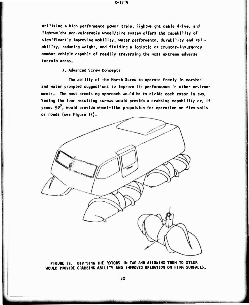
7. Advanced Screw Concepts
The ability of the Harsh Screw to operate freely In marshes
and water prompted suggestions to Improve Its performance In other environ-
ments. The most promising approach would be to divide each rotor In two.
Yawing the four resulting screws would provide a crabbing capability or, if
yawed 90 , would provide wheel-like propulsion for operation on firm soils
or roads (see Figure 13).
FIGURE 13, DIVIDING "TOE ROTORS IN TWO AND ALLOWING THEM TO STEER WOULD PROVIDE CRABBING ABILITY AND IHPROVED OPERATION ON FIRM SURFACES.
32
MM wmm M ..— _ M
K- i/m
8. Urban Combat Vehicles
In general, we are Ill-prepared for vehicle exploitation in
combat operations in an urban environment. We should therefore attempt
to develop vehicles which will operate freely in the congestion and rubble
that would be expected in cities under combat conditions.
o Sewer Vehicle.
Great use could be made of the city sewer system
by a vehicle which would enter through a manhole,
negotiate the sewer environment, and exit through
another manhole. Such a small vehicle could also
be used in cross-country environment to negotiate
dense, closely-spaced obstacles (rocks, trees) and
as a small amphibian.
o In-building Vehicle.
A vehicle which could enter a building, climb stairs
and knock down walls when necessary would provide neces-
sary mobility and fire power both inside and outside
bui Idings.
o Grabber.
The Grabber would employ 0 remote-controlled hook
or a man-amplified servo-mechanism to grab and propel
itself. In the urban environment, it could climb up
the outside of buildings; In the forest, It could grab
trees or rocks. The arms could be used alone to swing,
monkey style, from one "hand-hold" to another or, in
conjunction with conventional suspensions, to yield
assistance when appropriate. A simple variation of
the Grabber would be a mechanical foot to push, lift,
or pull a vehicle out of immobilizing situations.
33
R-1711*
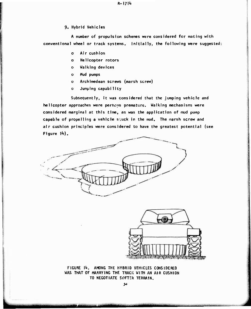
9. Hybrid Vehicles
A number of propulsion schemes were considered for mating with
conventional wheel or track systems. Initially, the following were suggested;
o Air cushion
o Helicopter rotors
o Walking devices
o Mud pumps
o Archimedean screws (marsh screw)
o Jumping capability
Subsequently, It was considered that the Jumping vehicle and
helicopter approaches were perhons premature. Walking mechanisms were
considered marginal at this time, as was the application of mud pump
capable of propelling a vehicle sluck in the mud. The marsh screw and
air cushion principles were considered to have the greatest potential (see
Figure ]k).
FIGURE l^t. AMONG THE HYBRID VEHICLES CONSIDERED WAS THAT OF MARRYING THE TRACK WITH AN AIR CUSHION
TO NEGOTIATE SOFTER TERRAIN.
mm HM
Major stumbling blocks in developing a hybrid air cushion/
wheeled or tracked vehicle are the cost, weight and complexity of provid-
ing two separate, independent propulsion and suspension systems. On the
other hand, it is feasible to construct inexpensive air cushion elements
without propulsion systems, to be utilized as barges which permit supplies
to be towed by cables or by a highly mobile vehicle over short stretches
of impassable terrain. These elements could be linked together to provide
auxiliary support to conventional vehicles or to form a bridge over which
conventional vehicles may pass. Since they will not have to operate very
far independently or to provide their own propulsion system, they could be
made quite simple, light and relatively inexpensive.
10, Wheel/Track Convertibles
There is a continuing need for logistic mobility in special
tactical and physical environments which is significantly greater than is
provided by high mobility tactical trucks in the fleet,, While operationally
critical, the number of vehicles required is relatively small and the de-
sirable variants are numerous. A potentially economical approach to this
problem is to design our tactical high mobility trucks so that, by the
field addition of suitable, integrated kits, some or all of the trucks
may be readily converted to viable tracked vehicles to fulfill low density,
extra-high mobility vehicle requirements. The basic concept would be to
employ the track conversion kits on a preplanned basis—according to
geographic location, season, large scale mission projections, etc. --
rather than on an ad hoc basis in response to rapidly changing tactical
situations; although the latter operational possibility would not be ex-
cluded. Such operational doctrine, plus current air lift capabilities,
should make it possible to avoid the "police syndrome" generally associated
with kits; I.e., that they are never there when you need them,
it is esseitial that the design approach minimize compromises to
cost and effectiveness of the host wheeled vehicles. It is equally im-
portant that conversion to tracked operation through the addition of the
kit produce a substantial mobility increment.
35
^MMi
Two approaches should be examined. The more desirable from
a parochial viewpoint is the design of the high mobility fleet for hybrid!'
zatlon from the ground up. In this approach, the scope of the kit modi-
fication can be minimized. Chassis articulation appears essential to
maximize the mobility increment. The alternative is to examine what might
be done by minor redesign of more standard truck configurations which
might be available from regular automotive production lines. Kit require-
ments might have to be expanded from simply a set of tracks to Include
added undriven axles, perhaps a chain drive sprocket, front wheel skis,
etc.
Detailed problems are foreseen In obtaining positive drive
between tires and the track in critical conditions (which may require
attention to a special tire), track throwing, poor ground pressure dis-
tribution (an important consideration, especially In snow) and potential
tire wear and damage. The philosophy of track design needs examination,
and tradeoffs among track life, weight, costs, and perforrr3nce must be
studied.
E, Propulsion Concepts
I. Direct Use of Energy at the Soil-Vehicle Interface
A dramatic savings in weight, complexity and efficiency could
be achieved if combustion energy would be used directly at or near the
soil-vehicle interface to obtain forward thrust. Such a system would
propel a vehicle directly from the combustion gases without passing the
energy through an engine-transmlssIon-drive line system.
The "red-sod" system employs direct combustion of a fuel-air
mixture to excavate soil. A take-off on this Idea would be the use of
open, vehicle-mounted cylinders which react fuel combustion gases directly
on the soil to produce thrust and control forces.
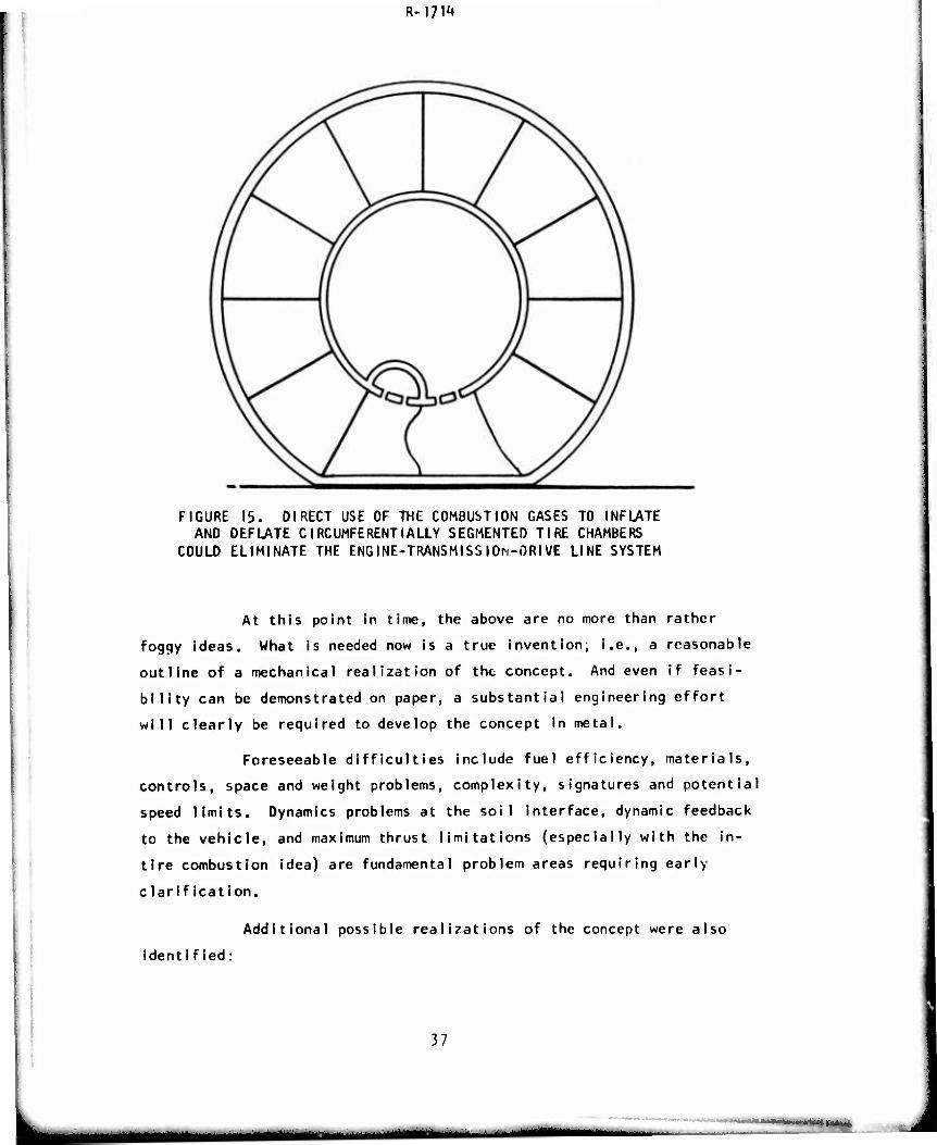
There is a Czeck Invention which utilizes compressed air to
propel a tire by sequential inflation and deflation of circumferential ly
segmented chambers (see Figure 15). The direct use of combustion gases,
rather than compressed air, would make this concept significantly more
attractive. Proper timing of the Intake and exhaust could be utilized to
provide spring and damping action In addition to propulsion.
36
«Mtf
R-m4»
FIGURE 15. DIRECT USE OF THE COMBUSTION GASES TO INFLATE AND DEFLATE CIRCUMFERENTIALLY SEGMENTED TIRE CHAMBERS
COULD ELIMINATE THE ENGINE-TRANSMISSIOM-ORIVE LINE SYSTEM
At this point in time, the above are no more than rather
foggy ideas. What is needed now is a true invention; i.e., a reasonable
outline of a mechanical realization of the concept. And even if feasi-
bility can be demonstrated on paper, a substantial engineering effort
will clearly be required to develop the concept in metal.
Foreseeable difficulties include fuel efficiency, materials,
controls, space and weight problems, complexity, signatures and potential
speed limits. Dynamics problems at the soil interface, dynamic feedback
to the vehicle, and maximum thrust limitations (especially with the in-
tire combustion idea) are fundamental problem areas requiring early
clarification.
Additional possible realizations of the concept were also
ident ified:
37
i WMI
imm—m ■MUH
o Use of reaction thrusters exploiting (in some unspecified
way) ground effects subsUint la Hy to Increase static thrust.
o Development of a waveform contact area deriving directly
from in-unit combustion.
o Use of the in-tire combustion idea in a bag-type track.
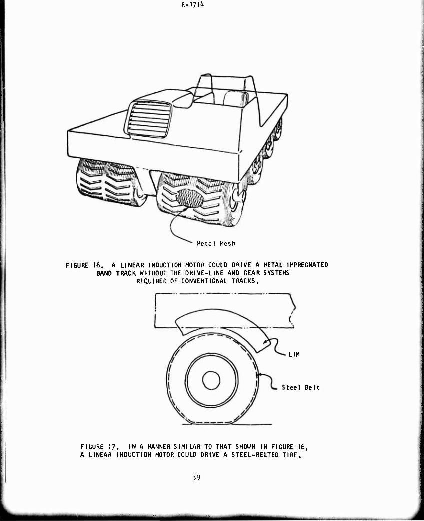
2. Linear Induction Motor Applications
Current research developments in linear induction motors offer
possibilities of simplifying track drive systems and of separating the
propulsion task from the suspension task.
o A LIM mounted in the vehicle could propel a track (Figure 16)
or wheel (Figure 17) without the drive-line and gear systems
required for conventional electrical drive systems.
o For a tracked vehicle, a LIM system would reduce the losses
inherent In sprocket drive systems,
o Magnetic systems or air bearings could be utilized to
provide suspension support.
Successful implementation of any of these ideas requires de-
velopment of low cost, durable and efficient linear induction motors which.
In turn, require development of low cost super-conducting materials,
preferably operating at room temperature. There are inherent problems
associated with generating inefficiencies, electro-magnetic radiation
(signatures and safety), maintenance, vulverabiIity and durability due to
exposure to elements.
Linear induction motors may or may not be the best approach
to eliminate the severe restrictions imposed by mechanical drive systems.
To account for this possibility, the following list of general develop-
ment goals for any electric drive for use In a mobility system application
was formulated:
38
m^mm
R-]7^
Meta! Mesh
FIGURE 16. A LINEAR INDUCTION MOTOR COULD DRIVE A METAL IMPREGNATED BAND TRACK WITHOUT THE DRIVE-LINE AND GEAR SYSTEMS
REQUIRED OF CONVENTIONAL TRACKS.
LIM
tee I Belt
FIGURE 57. INA MANNER SIMILAR TO THAT SHOWN IN FIGURE 16, A LINEAR INDUCTION MOTOR COULD DRIVE A STEEL-BELTED TIRE.
39
m—m
R-l?!**
o Greater transmission efficiency (in the order of 80 to
9CF/, for the total system) over most of Its operatinq
range.
o Lower weight and cube motors (at outside, should not weigh
more than an equivalent mechanical drive system).
o Production cost comparable to mechanical drive system.
o No final reduction drive torque multiplier.
o Simple, low cost control systems.
3. Alternate Fuels
Our dependence on hydro-carbon fuels makes our field forces
extremely vulnerable In the case of a critical fuel shortage caused either
by the growing world-wide depletion of fossil fuels or, on a smaller scale,
by the Interruption of our normal supply sources. Four related solution
approaches were Identified:
o More efficient utilization of combustion waste products
(heat, gas flow) by utilizing them to power auxiliary
systems (heaters, electrical generators, turbo-chargers,
etc.).
o Systems to manufacture, store and transport large quantities
of synthetic or substitute fuels (hydrogen, methane, propane,
etc.).
o New propulsion systems or adaptations of existing systems
which can operate well on substitute fuels.
o Propulsion systems which can operate on Indigenous fuels
(coal, wood, waste products, etc.). Steam, Sterling, Brayton
and Minto engines offer possibilities in this area.
k. Microwave Power Transmission
Recent studies indicate that energy transmission by microwaves
can have relatively high efficiency. Thus, microwave energy, generated at
mobile rear area generators could be used to power suitably designed
vehicles and weapon systems. The power stations would be nuclear or burn
indigenous fuels. Potential advantages are:
ho
mm
K-i/rH
o Less use of scarce petroleum fuels.
o Lighter, more air-transportable vehicles.
o Lower Individual vehicle d*>tprticn signatures.
o Suitable to modular electric drive concepts.
5. Hybrid Power Concepts
The incorporation of dual power systems in combat vehicles
holds the promise of utilizing inexpensive, efficient fuels at times of
low power requirements, yet having the capability of generating high power
at the relatively fewer times when such levels are required. Energy for
peak loads could come from the use of special fuels or explosives or
could be generated during times of low power requirements and stored for
later, short-term use.
F. Flotation and Traction Aids
A number of devices were suggested that could be utilized to
enhance conventional vehicles by providing augmented flotation or traction.
The more promising concepts are listed below.
1. Limited Slip Differentials
The continuous and properly proportioned distribution of
driving torque to all wheels under varying tractive and wheel loading
conditions is a prime requisite for improved off-road mobility on multi-
axle wheeled vehicles. To achieve this goal, limited slip differentials
with 100% torque bias capability are essential. Present locking differen-
tials are complex, costly and unreliable. A program to develop a simple,
workable system is urgently needed.
2. Band-Type Tracks
Band tracks offer reductions in noise, vibration and power
consumption. Whle such tracks exist for lighter vehicles, there are
none presently for vehicles in the 10,000 to 120,000 pound weight range.
A series of narrow, lower capacity bands, mounted in parallel would be
a first approach to increasing band track capabilities.
k\
■MM^aMdMMM
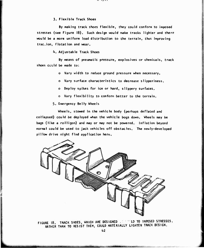
3. Flexible Track Shoes
By making track shoes flexible, they could conform to imposed
stresses (see Figure 18). Such design would make tracks lighter and there
would be a more uniform load distribution to the terrain, thus improving
traCvion, flotation and wear.
k. Adjustable Track Shoes
By means of pneumatic pressure, explosives or chemicals, track
shoes ccild be made to:
o Vary width to reduce ground pressure when necessary.
o Vary surface characteristics to decrease siipperiness.
o Deploy spikes for ice or hard, slippery surfaces.
o Vary flexibility to conform better to the terrain.
5. Emergency Belly Wheels
Wheels, stowed in the vehicle body (perhaps deflated and
collapsed) could be deployed when the vehicle bogs down. Wheels may be
bags (like a rolligon) and may or may not be powered, inflation beyond
normal could be used to jack vehicles off obstacles. The newly-developed
pillow drive might find application here.
FIGURE 18 TRACK SHOES. WHICH ARE DESIGNED . " ' LD TO IMPOSED STRESSES, RATHER THAN TO RESIST THEM, COULD MATERIALLY LIGHTEN TRACK DESIGN.
1*2
...*_^^MM*i -■- ■ -' -
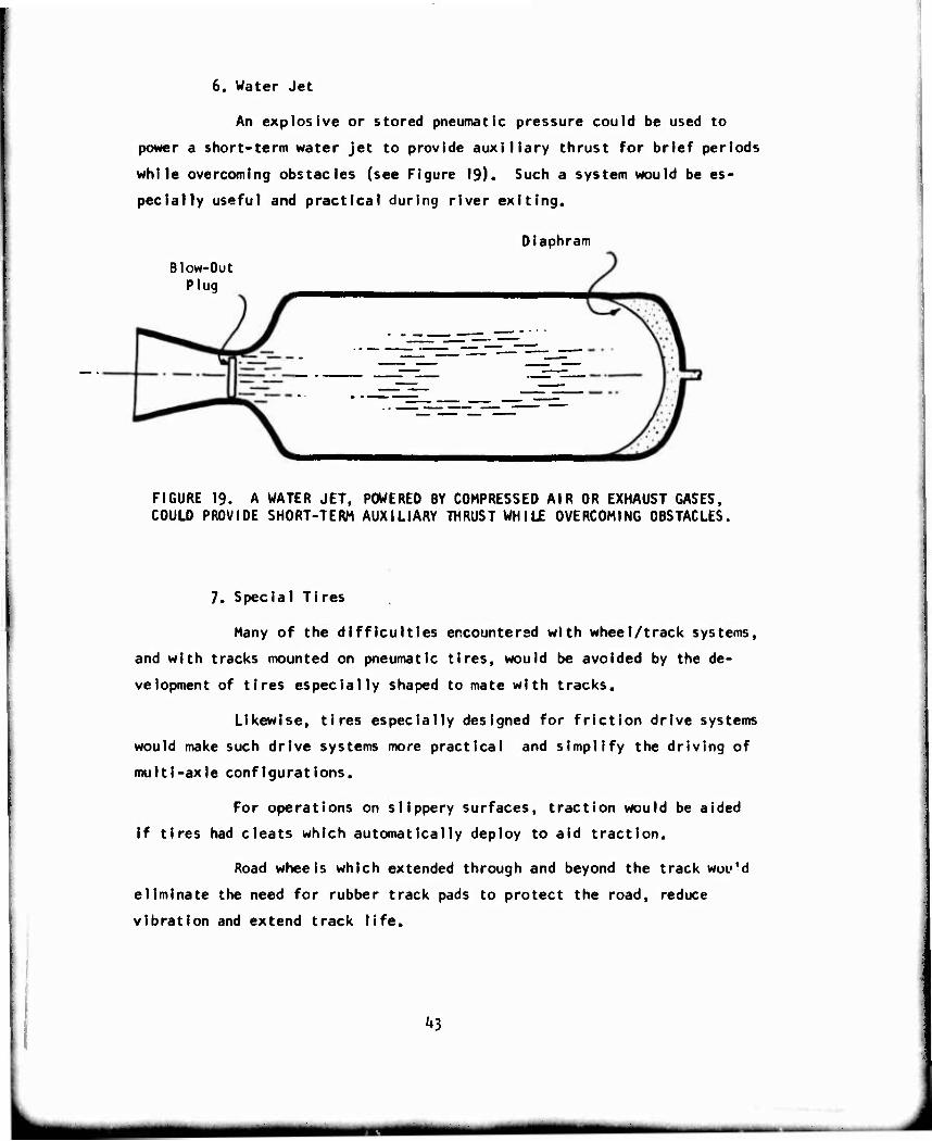
6. Water Jet
An explosive or stored pneumatic pressure could be used to
power a short-term water jet to provide auxiliary thrust for brief periods
while overcoming obstacles (see Figure 19). Such a system would be es-
pecially useful and practical during river exiting.
Diaphram
Blow-Out Plug
FIGURE 19. A WATER JET, POWERED BY COMPRESSED AIR OR EXHAUST GASES, COULD PROVIDE SHORT-TERM AUXILIARY THRUST WHILE OVERCOMING OBSTACLES,
7. Special Tires
Many of the difficulties encountered with wheel/track systems,
and with tracks mounted on pneumatic tires, would be avoided by the de-
velopment of tires especially shaped to mate with tracks.
Likewise, tires especially designed for friction drive systems
would make such drive systems more practical and simplify the driving of
multi-axle configurations.
For operations on slippery surfaces, traction would be aided
if tires had cleats which automatically deploy to aid traction.
Road wheels which extended through and beyond the track wou'd
eliminate the need for rubber track pads to protect the road, reduce
vibration and extend track life.
^3
G. External Mob!Iity Aids
In addition to integral traction and flotation aids, a number of
external aids were suggested to enhance mobility.
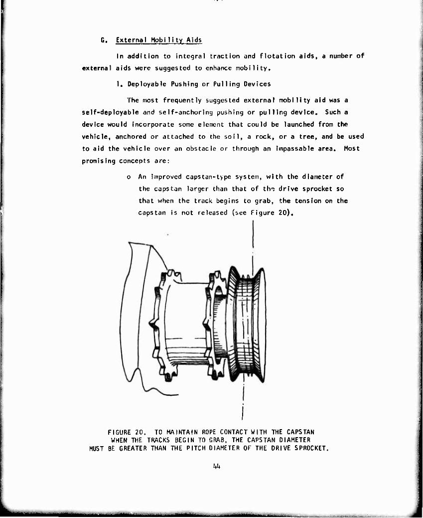
I. Deployable Pushing or Pulling Devices
The most frequently suggested external mobility aid was a
self-deployable and self-anchoring pushing or pulling device. Such a
device would incorporate some element that could be launched from the
vehicle, anchored or attached to the soil, a rock, or a tree, and be used
to aid the vehicle over an obstacle or through an impassable area. Most
promising concepts are:
o An improved capstan-type system, with the diameter of
the capstan larger than that of th«? drive sprocket so
that when the track begins to grab, the tension on the
capstan is not released (see Figure 20),
FIGURE 20. TO MAINTAIN ROPE CONTACT WITH THE CAPSTAN WHEN THE TRACKS BEGIN TO GRAB, THE CAPSTAN DIAMETER
MUST BE GREATER THAN THE PITCH DIAMETER OF THE DRIVE SPROCKET,
Uh
MMi
o A cybernetic gripper that uses man-^mpllfied servo-
mechanisms to reel In an anchored cable.
o A rapidly emplaced system like a ski tow, which could
be used to pull vehicles up embankments or through soft
terrain.
o A system which synchronizes winch speed and track or
wheel speed to enable both systems to aid propulsion
without fouling.
o An anchor launching system ./hich utilizes a fuel-air
mixture or exhaust gases as a propellent.
o A simple, exhaust-powered ram, capable of pushing
against the soil, rocks, trees or other protuberances.
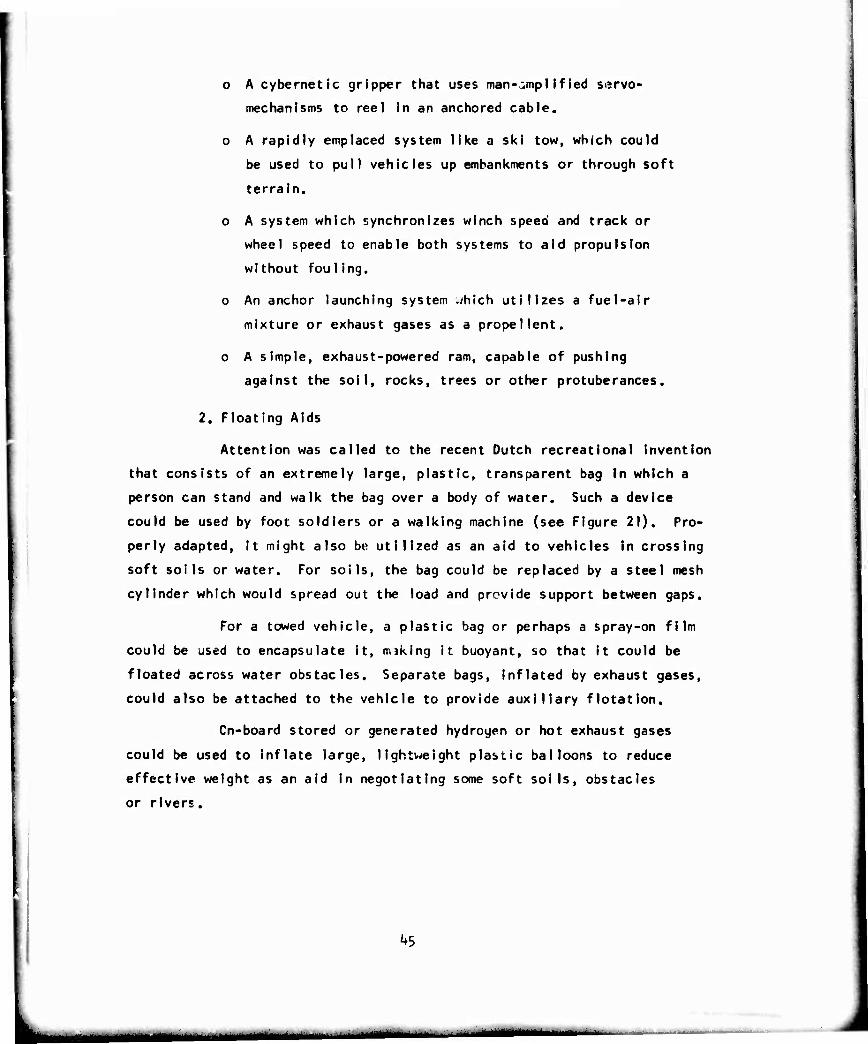
2. Floating Aids
Attention was called to the recent Dutch recreational Invention
that consists of an extremely large, plastic, transparent bag in which a
person can stand and walk the bag over a body of water. Such a device
could be used by foot soldiers or a walking machine (see Figure 21). Pro-
perly adapted, It might also be utilized as an aid to vehicles in crossing
soft soils or water. For soils, the bag could be replaced by a steel mesh
cylinder which would spread out the load and provide support between gaps.
For a towed vehicle, a plastic bag or perhaps a spray-on film
could be used to encapsulate it, miking it buoyant, so that It could be
floated across water obstacles. Separate bags. Inflated by exhaust gases,
could also be attached to the vehicle to provide auxiliary flotation.
Cn-board stored or generated hydrogen or hot exhaust gases
could be used to Inflate large, lightweight plastic balloons to reduce
effective weight as an aid In negotiating some soft soils, obstacles
or rivers.
kS
^^^MUMMMMi
R-l?!1*
FIGURE 21. A PLASTIC BUBBLE WOULD ALLOW A FOOT SOLDIER TO •VALK ON WATER". SUCH A DEVICE IS PRESENTLY IN USE
FOR RECREATIONAL PURPOSES.
3, Terrain Modification Aids
Vehicle-mounted terrain modification aids offer great promise,
since they need be mounted on only a few vehicles to improve the mobility
of many.
o A vehicle-mounted back-hoe, front end loader, or similar
device, could be used to demolish steep banks, remove
obstacles, fill in gaps, etc. (see Figure 22).
o A high-pressure hose could be used at river banks to wash
away steep banks and make them gentle enough for vehicles
to mount (see Figure 23).
^6
J
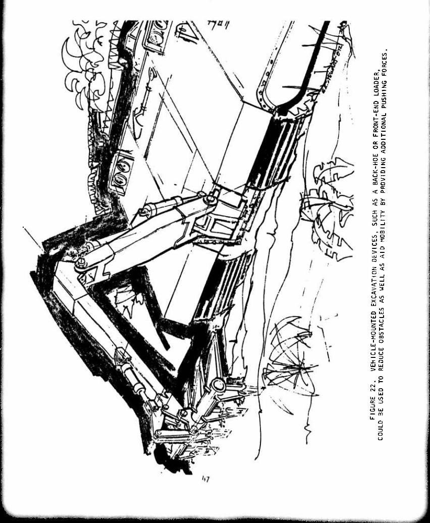
LU
«re Ul
ü to
Q Z3 Z O. LÜ I -I
O Q < LU o o x z i — ^ o o — < > OD O
S < Q-
< CO
X >- O I- Z3 — CO -J
. 03 >/> O LU T
— n > — a z < o
< UJ
< O W1 X < LU
•St a uj LU -I f- u z < => I- O lO i: to
— 3 X Q LU LU > a:
• P CM fM Q
Ul LU Ul
O LU — m
o o
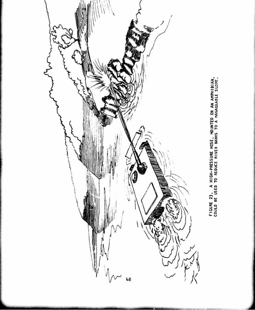
= 3
la < CO
< o
Ü
-z to m o X oc
ÜJ
= oc
to UJ tu o ?2 Q. Q I uj X QC o = p
< Q UJ
(M UJ CO
UJ
^3 US
o Vehicle-mounted chain saws could be used to remove
vegetation which obstructs mobility or to emplace
vegetation which would aid mobility.
o Bangalore-type torpedoes could clear vegetation, rocks
or other obstacles could be used to demolish banks.
o Quick-setting foams or epoxies could be used to strengthen
soil, reduce the s Upper iness of banks or fill in gaps
(water courses, ditches, bomb craters). The foam could
either combine with the water to form firmer terrain by
extracting moisture from the soil or it could overlie
the soli thereby effectively reducing ground pressure;
also small areas could be hardened to provide anchoring
points for winches or pushers,
o Accelerated hardening of disaggregated snow, as developed
for Arctic landing fields, could be applied to off-road
vehicle operations in snow,
o Rolls of fencing could be dropped in trenches or placed
alongside steep banks (see Figure Zk), During World War I,
British tanks carried such devices (called fascines).
Today we could use lightweight inflatable or foaming
materials.
o Adjustable ramps, set at the proper angles, could provide
smooth launch and recovery of vehicles crossing gaps, banks
or other obstacles. Such systems are now commonly used
by "car rodeos," For military applications, the systems
would require a calculating facility to establish the proper
launch angle and velocity and the matching recapture
contour (see Figure 25).
^9
in ' ■ ^-mtmmmmt
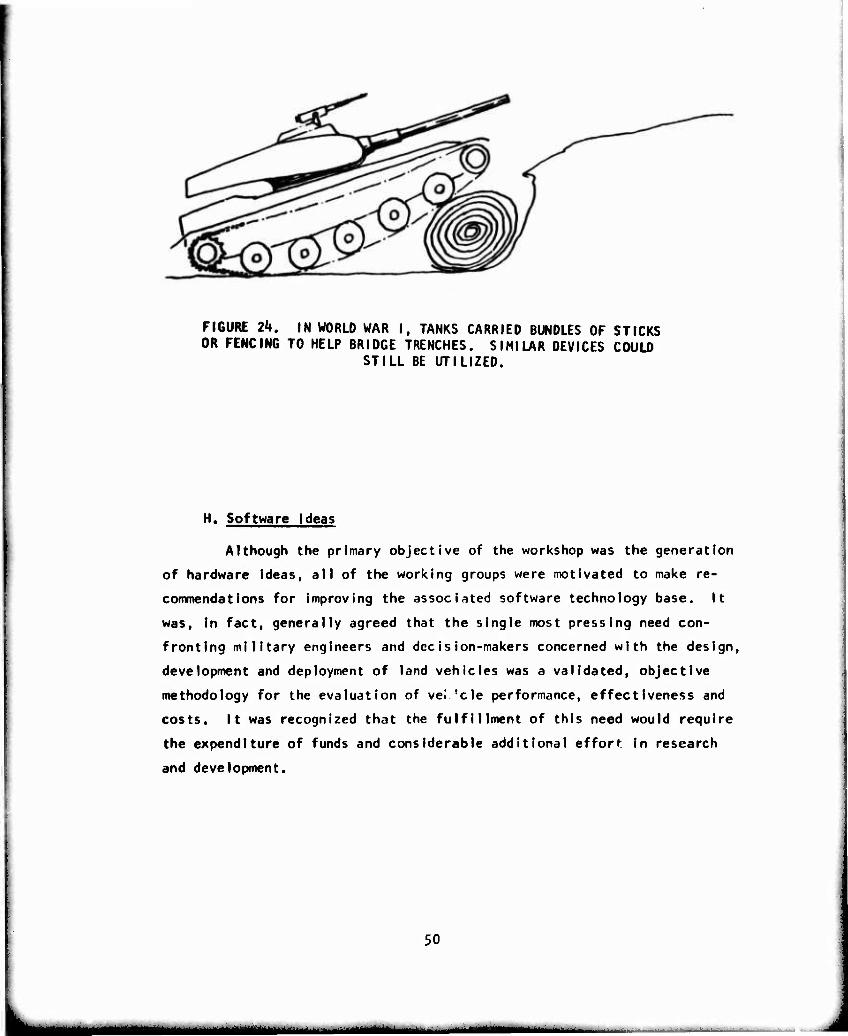
FIGURE 2k. IN WORLD WAR I, TANKS CARRIED BUNDLES OF STICKS OR FENCING TO HELP BRIDGE TRENCHES. SIMILAR DEVICES COULD
STILL BE UTILIZED.
H. Software Ideas
Although the primary objective of the workshop was the generation
of hardware ideas, all of the working groups were motivated to make re-
commendations for improving the associated software technology base. It
was, in fact, generally agreed that the single most pressing need con-
fronting military engineers and decision-makers concerned with the design,
development and deployment of land vehicles was a validated, objective
methodology for the evaluation of vel 'cle performance, effectiveness and
costs. It was recognized that the fulfillment of this need would require
the expenditure of funds and considerable additional effort in research
and development.
50
MIMB ^ ^ _ ____ .. . .
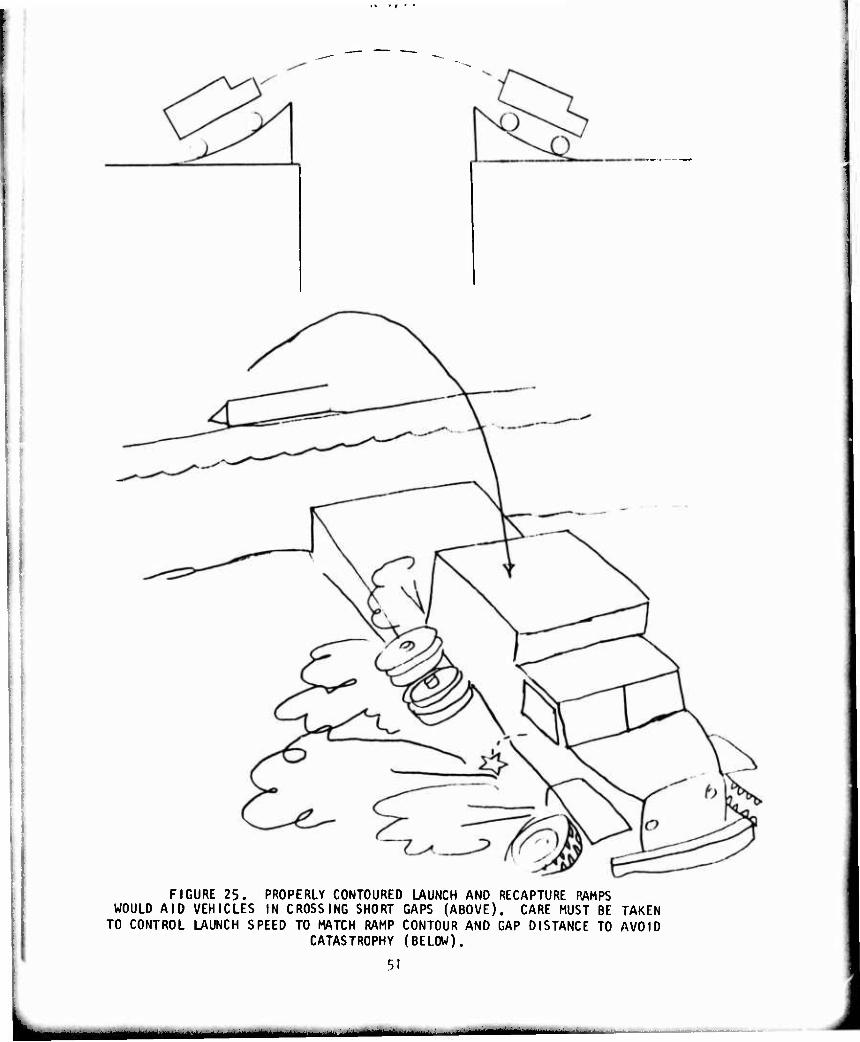
FIGURE 25. PROPERLY CONTOURED LAUNCH AND RECAPTURE RAMPS WOULD AID VEHICLES IN CROSSING SHORT GAPS (ABOVE). CARE MUST BE TAKEN
TO CONTROL LAUNCH SPEED TO MATCH RAMP CONTOUR AND GAP DISTANCE TO AVOID CATASTROPHY (BELOW).
r>l
1. Simulation Development
As a fundamental step In the development of this methodology,
simulations which accurately predict vehicle performance are essential.
a. Mobility Models.
The success of the AMC-71 Mobility Model, even in its
preliminary form, demonstrates the potential of such an evaluation tool.
This model must be validated, refined and expanded. Among the more
pressing areas requiring further development are those associated with:
o Ride.
An extended ride prediction model must be deve-
loped. The present model simulates only rigid-framed
vehicles. This model must be extended to account
for frame flexibility and articulated vehicles.
o River Cross ings.
One of the most severe obstacles to off-road
operation is the negotiation of inland rivers and
streams. A model which accurately predicts vehicle
performance in the water and while exiting is of
prime importjnce.
o Traction.
The predictive traction models developed by WES
and Bekker are only a first-cut approximation. Since
traction is an underlying performance factor for
almost all mobility modeling. Valid, accurate traction
models which include slip rate must be developed.
o Obstacle Negotiation and Avoidance.
Present obstacle negotiation and avoidance models
are not validated; they must be validated and upgraded
where necessary to achieve acceptable engineering
accuracy.
52
■Mdaaa
r\- i / I"
o Driver Performance.
We have no adequate driver behavior and perfor-
mance mathematical models. Most urgent requirements
are those associated with visibility, speed selection,
response to input shocks and vibration, and route
select ion.
b. Laboratory Simulations.
There is a companion need for the expansion of laboratory
facilities to conduct dynamic simulation testing of elemental components
and total vehicle systems. Such laboratory facilities would minimize
the subjectivity which enters Into the evaluation of vehicle sub-systems,
compare competitive configurations against the same baseline, and provide
tools for the development of the mobility models discussed above.
o RAM-0.
A great need exists for laboratory facilities which
can realistically exercise complete vehicles as well as
vehicle sub-systems. The ability to determine function-
al reliability and durability prior to field performance
tests will save time and money as well as improving the
RAM-D performance of field systems.
o Man/Machine Interface.
Operational simulators must be developed to evaluate
the performance of the man in the vehicle system. The
seat simulator at TACOM is but a first step in the deve-
lopment of needed man/machine itudy tools which can be
used to investigate pertinent aspects of human behavior.
o Riverine Performance.
Field tests are extremely expensive. In the case of
river crossings in swift streams, they are also dangerous.
A river simulator for testing of properly scaled down
vehicles would provide a less expensive, safer method
for conducting preliminary evaluation of river-crossing
designs and techniques, and would also provide a useful
53
L.
tool for the development of a valid river crossing
mathematical model.
o Vehicle/Soil Interaction.
Vehicle traction performance models can only be pro-
perly evaluated under the controlled conditions available
in a soil bin dynamometer facility. Adequate facilities
exist at TACOM, WES and Stevens Institute of Technology;
they must be properly utilized to develop the relation-
ships needed for the mobility models.
o Physical Scale Modeling.
Greater use of physical scale models in the development
of vehicles and their sub-systems should be utilized. Many
concepts can be investigated in scale model form at a
fraction of the full-scale price.
c. Operational Simulations.
There are many operational simulations presently in use.
None of these, however, adequately reflect the mobility and RAM-D character-
istics of the vehicles involved, and their dependence upon the terrain and
the environment.
d. Cost Modeling.
Much work must be done on the establishment of a proper
data base before valid cost models can be formulated.
2. Simulation Applications
Once the simulations discussed above are available, they
should then be employed in a wide variety of development applications.
o Computer-Aided Design.
Proper mathematical performance models and new visuali-
zation techniques can be used as a valuable aid In the early
concept design phase.
5^
L ^MMMB
n- I / I1-
o Equipment Evaluation.
RAM-0 and other laboratory simulations can be utilized
to evaluate a particular design or to compare competitive
configurations. Interfacing of these simulations with
higher order combat effectiveness models will provide an
evaluation of how the equipment will serve the Army in the
field.
o Tactics Development.
The use of new equipment frequently allows the commander
to employ his forces in new, more effective ways. Combat
and logistical simulations, in addition to evaluating a
proposed concept, can be used to determine how best to
explo it it In the f ield.
o Parametric Design Studies.
Systematic cvaulations of different but related concepts
can be performed to characterize the influence of design
factors on vehicle operational performance.
3. Exploratory Prototypes
The proposed use of simulations docs not in any way preclude
the need to conduct full-scale tests in the field. No model, however
sophisticated, can predict all that may occur in the field. There is
thus a requirement as a logical complement to the simulation approach for
the construction and testing of exploratory prototype vehicles to evaluate
definitively new concepts.
55
IV. CLOSURE
The ideas presented in this report, taken collectively, are con-
sidered to constitute a premising starting point for a program of mobility
research and development. The next logical steps in the process of imple-
menting such a program are as follows:
1. Analyze t'e potential risks and benefits associated with each
concept presented in Section ill.
2. identify those concepts which appear most promising on the
basis of risk-benefit considerations.
3. identify the pacing technological problems associated with
each high benefit/risk potential concept.
k. Design and implement specific research and development projects
directed towards the solution of these pacing problems.
56
J
APPENDIX A
ORGANIZATIONAL DETAILS AND METHODOLOGY
Part icipants
Basically, the participants at the workshop feM into three cate-
gories: 000 experts in the field of military vehicles or nobility
(personnel from this group were assiyned the tasks of conducting the
briefing orientations, chairing the committees, and conducting the workshop
administrative chores); personnel from civilian life with wide technical
backgrounds who were known to oc innovative in tneir thinking and accomplish-
ments; and non-tecnnicaI individuals (who were Included in the workshop
in order to bring fresh ideas and approaches in'c the discussions which would
require all participants to think in new rec.tions).
The complete list of participants is included in Appendix B. Each
participant was sent a briefing statement contained In an orientation
letter (Appendix C) and a copy of "Ground Crawling, ]Qff; the State-of-the-
Art in Off-Road Mobiiity," by C.J. Nuttall. The purpose of the briefing
statement was to inforn the attendees, of the purpose of trie workshop,
Its scope, and its detalJec objectives, and tc provide some background in-
formation. Mr. Nuttall's cexr was intended to familiarize attendees with
what has been accomplished In tue past and to serve as a basic reference
for those not up-to-date in ground mobility.
Steering Coniniitiee
The Workshop Steering Committee consisted of * ive persons:
Dr. I. Robp-t Ein iicn, Stevens Institute of Technology, Chairman
Lt. Col. Frank Cantwell, Headquarters, Army Material Command
Mr. James Carr, Heaac^ärters, Army Material Command
Mr. Howard J. Duqoff, U S. Army Tank-Automotive Command
Mr. Adam Rula, U.S. Army Engineers Waterways Experiment Station
A-1
r\- I / i*t
It was the responsibility of the Steering Committee to plan and or-
ganize the sessions, to select and invite the attendees, to outline the
content of the briefings, to obtain the briefers, to make all the adminis-
trative, housing and social 01rangements, and to prepare the written report
of the workshop rfisuks.
Creative Resource Staff
To aid in the conduct of the workshop, the Steering Committee engaged
the services of a Creative Resources Staff. They were:
Dr. Joseph McNeill, Consultant;
Mr. Augustine E. Magistro, U.S. Army Munitions Command, Resource Leader: and
Ms, Marie Ranger, Consultant
Dr. McNeill and Mr- Magistro organised and prepared the initial creative
session material and briefed the team chairmen prior to the start of the
workshop session. Direction of the detailed operations and creative
portions of the workshop sessions during the four-day session was provided
by Mr. Magistro and Ms. Ranger.
Tean. Organization
The attendees were divided Into six teams of six to eight members
each. The chairman of earn tram was preselected and was prebriefed on
methods for conducting creative ream sessions. Each team was assigned a
separate room for the -ronduct or its deliberations.
The teams stayed togetner throughout the workshop. The chairman
was charged with creating a cohesive team and guiding the deliberations
along predetermined paths.
Team selection was conducted In several ways. About half of the
participants completed the IPAT Form A test which was scored by the
Laboratory of Psychological Studies of Stevens Institute of Technology.
from the profiles provided by this test, these participants were assigned
to trains to assure heterogeneous team organization on the basis of key
personality factors including willingness to experiment, imaginative skill,
A-2
mmmm
and assertivenfias. Also, team participants were selected to provide each
team with a broad range of technological specialities related to the
mobility problems assigned to each team. Each team included at least
one person who knew very little about the mobility problem, to bring a
fresh outlook to the sessions and cause the "expert" members to examine
ideas which they might have otherwise rejected due to bias or preconceived
evaluation of merit. A special effort was made to include women parti-
cipants on each team since their presence causes male members to look in
new directions, much removed from their normal course.
Teams were structured so that supervisory personnel were not teamed
with working level technical personnel and, in most cases, the team forma-
tion followed the rule of a single job level for all members. In those
cases where several job levels were present on teams, no serious problems
were noted in idea output. The use of the IPAT for team selection reduced
the selection problems to a minimum.
Methodol £21
The main technique for producing new ideas and concepts for Improved
mobility technology was "bra instorming. " This technique is one of the
most frequently used by participants whose experience in the intentional
generation of ideas is limited. The technique has simple rules which are
learned in less than an hour. Thus the participants become effective
very quickly. The rules of operation are stated In Appendix D.
The use of braInstorming is designed to help participants to emerge
from their technological ruts and to allow them to produce many ideas in
a short period of time. Although a typical session will vary in effi-
ciency, from three to ten percent of the ideas generated are significant.
Thus, It is the ability of the group to produce hundreds of ideas that
make the technique an important technological tool. Also, those parti-
cipants who are active In the mobility field continue to think of the
concepts discussed and to generate new Ideas long afterwards, which, by
virtue of their position, they are able to apply.
A-3
^_ —-—-^.
The use of suspended or deferred judgement (no one criticizes an
idea, no matter how "ridiculous") and the encouragement of free-wreeling
and wild ideas help to produce a widely divergent output that is far
removed from tne common or traditional lines of thought that may inhibit
the production of novel ideas. The continuous flow of ideas from an ex-
perienced team of six to eight persons can easily proc'uce more than 100
ideas per hour; inexperienced teams generate about 60 ideas per hour.
To offset the idea-recording problem, each participant is provided with
many 5" * 8" cards to record his ideas and to make simple conceptual
sketches.
Techniques used by teams include deferred judgement, the forced
production of a large quantity of ideas, and the use of "hitchhiking"
(taking an idea and modifying it to create a new idea). The technique
which had the greatest impact in this workshop was the ruling out of
criticism or the deferred judgement technique.
The objective of each idea work shop session is the production of
many ideas, not just a few carefully considered ones. Evaluation and the
selection of the "best" Ideas are performed as a later task of the workshop.
When the idea or sketch is recorded on a 5" x 8" card, the objective is
not to create a work-of-art or an engineering marvel, but to try to cotmiuni-
cate the essence of the ideas, to generate raw ideas with as little editor-
ializing as possible, to move along, free-wheeling, to think, to modify,
and to expand on the ideas presented.
The workshop idea sessions varied in length from about one to three
hours for a total of about 15 hours during the four-day period. The
sessions were divided frequently by breaks and coffee at random intervals
and the idea car count was checked frequently to determine when idea
output was lagging. The teams learned the rules of brainstorming quickly,
but early sessions contained many distractions such as editorialization
and long idea descriptions.
A-4
mmHammi i —
Team leaders were briefed and Instructed on corrective actions at
m,.itings held daily with steering committee members and resource leaders.
A key factor in idea generation is the participants' alertness and incen-
tive to generate a large quantity of ideas. The team leader's responsi-
bility is to detect any degradation in the team's performance and to
provide corrective action, if the idea output lags, a review of the
problem statement is conducted and the problem restated to reduce or re-
focus the scope.
A-5
m^^m^mi^m^mtm^mmmam
Brtefinas
Briefings were held In a number of areas associated with mobility«
The briefings were designed to present to the participants a wide variety of
concepts that had been tried in the past, the present state of mobility
development, the plans for future Army automotive concepts, and the mobility
activities of other nations- The briefings presented are listed here by
title and author only; detailed briefings may be obtained by contacting the
author directly:
Definition of the Mobility Problem - H. Dugoff
Historical Development of Mobile Vehicles - C. J. Nuttall
Engine Developments - D. Latson
Suspension Developments - R. Patek
Foreign Vehicles - D. Flerer
Current Army Vehicle Fleet and Drawing Board Plans - P. Jones
Modular Vehicles - J. Winkworth
Briefing sessions were also held to orient the participants in the
creative processes, to introduce the techniques to be used within the teams,
and to release their creative potential. Risk-free creative activities were
also provided to illustrate the desired team operation. These intlal activities
allowed participants to experience the use of the key creative tools and to
point out typical blocks which inhibit creative thinking.
The participants were provided with a number of mobility briefing
documents that were to be used during the workshops to help define the mobility
problems to be attacked. The briefing documents described the creative challenge
told something about the situation, stated the parameters, and listed some ideas
for team consideration. The briefing document gave only enough information so
each team member had some initial understanding of the problem and it was anti-
cipated that, as the team operated on the problem, the problem statement would
be revised by the team. Copies of the briefing documents used are contained in
Appendix D.
A-6
«MBH

Task AssIgnments
Since the field of mobility is so broad, each team was assigned a
special problem area for deliberation in order to narrow the problem to
a manageable size. The initial team assignments were to look at future
technological advances that may be forthcoming in the next 10-20 years
and to determine how these advances might be translated into an improve-
ment in mobility. Each team was assigned different aspects of this problem
as follows:
Team #1 — The man/machine/environment interface — Rula, chairmar.
Team til — Vehicle morphology (shape and arrangement) — Carr, chairman.
Team ^3 — vraction systems — Dugoff, chairman.
Team ttk — Propulsion systems — Latson, chairman.
Team //5 ~ Suspension systems — Patek, chairman.
Team ^6 — Control systems — Nuttall, chairman.
Although teams were later allowed to look into areas not assigned, the ideas
generated indicate that, in general, each team tended to continue along the
path first assigned. The detailed briefing document of each Team is pre-
sented in Appendix E.
Next, each team was assigned mobility problem environments where they
were to apply the new technological developments discussed previously. Team
assignment«; were as follows:
Problem Area
Obstacles
River crossings
Snow
Soft soils
Siippery surfaces
Steep slopes
Dense vegetation
Urban areas
Rough terrain
Teams Assigned
I and h
1 and 5
1 and 6
2 and k
2 and 5
2 and 6
3 and U
3 and 5
3 and 6
A-7
^_»J
As an aid to the development of hardware ideas, each team was requested
to list the characteristics of each environment. These lists appear In
Appendix F.
In each environment, each team was to attempt to think of hardware
approaches that utilized concepts Incorporating at least one of each of
the following approaches:
WheeIs
Tracks
Air cushion
Unconventional, novel, or new systems
Hybrid combinations
Add-on kits to existing concepts
External aids (mats, etc.)
Finally, each team developed a set of evaluation criteria and, by
examining each idea in turn, assigned a three-level rating: yes, maybe,
no. From the "yes" category they then selected and expanded upon the
ten concepts that they thought to be best; some teams, however, expanded
on more than ten concepts.
It was the Intention of the steering committee to have each team
work on an actual vehicle concept; however, as the workshop progressed,
it was felt that the time would be better spent expanding on the above
activities.
The detailed ideas generated are presented in Appendix G and the
best concepts selected are presented in Section IV of this report.
Agenda
Only an agenda outline (Appendix C) was distributed to the attendees
so that they would not anticipate future events. The master agenda, known
only to the steering committee, is contained In Appendix H. Although it
was considered to be only a guide, It worked out that it was followed
rather wel 1.
A-8
Administrative Matters
Most of the administrative matters were covered In the letter of In-
structions sent to each attendee prior to the meeting. This letter Is
contained in Appendix C.
General
The brainstorming sessions satisfied the objective of producing a
large quantity of material in a short time. More than 75 ideas were se-
lected by the teams for further processing. Additional sessions are
recommended to process and improve the ideas developed. Special workshops
in each general area discussed in Section IV should be held to amplify the
start made at Durham. The organization of the idea improvement and imple-
mentation sessions will require a significant amount of planning and,if
the effort is inadequate,many ideas will be discarded or overlooked.
In most creative activities where ideas are intentionally generated,
the raw output must be examined carefully to see how it can be reduced to
practice. The session at Durham did not address itself to the problems
of reduction to practice of the ideas generated or a plan of action to
achieve idea implementation. This activity is clearly beyond the scope of
the authors of this report since it will require the establishment of pro-
grams and fundings to investigate the areas and to achieve the objectives
presented.
The general consensus of participants was that the objective to un-
cover innovative Ideas that will materially improve Army mobility was
achieved and that the experience, though personally fatiguing or frustrat-
ing during the early sessions, al lows them,for the first time, intent ional ly
to learn to exercise their imagination, to increase their fluency in pro-
ducing ideas, and to augment their willingness to accept and to be tolerant
of new ideas and of those that produced them.
A-9
mmm
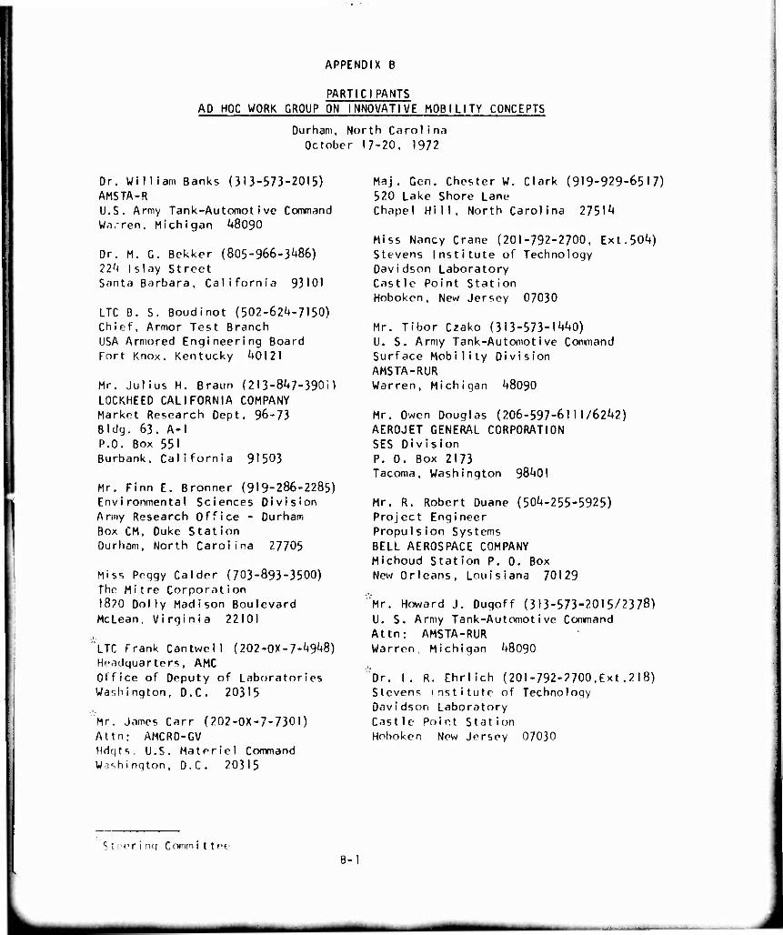
APPENDIX B
PARTICIPANTS AD HOC WORK GROUP ON INNOVATIVE MOBILITY CONCEPTS
Durham, North Carolina October 17-20, 1972
Or. William Banks (313-573-2015) AMSTA-R U.S. Army Tank-Automotive Command Wa.-ren, Michigan ^8090
Dr. M. G. Bekker (805-966-3^86) 22h Islay Street Santa Barbara, California 93IOI
LTC B. S. Boudinot (502-62^-7150) Chief, Armor Test Branch USA Armored Engineering Board Fort Knox, Kentucky U0I2I
Mr. Julius H. Braun (213-8^7-3901) LOCKHEED CALIFORNIA COMPANY Market Research Dept, 96-73 Bldg. 63, A-l P.O. Box 551 Burbank, California 91503
Mr. Finn E. Bronner (919-286-2285) Environmental Sciences Division Army Research Office - Durham Box CM, Duke Station Durham, North Carolina 27705
Miss Peqgy Calder (703-893-3500) The Mitre Corporation I8?0 Dolly Madison Boulevard McLean, Virqinia 22101
LTC Frank Cantwell (202-0X-7-/^8) Hoadquarters, AMC Office of Deputy of Laboratories Washington, D.C. 20315
Mr. James Carr (202-OX-7-730I) Attn: AMCRD-GV Hdqts. U.S. Materiel Command Washington, D.C. 20315
Maj. Gen. Chester W. Clark (919-929-6517) 520 Lake Shore Lane Chapel Hill, North Carolina 2751^
Miss Nancy Crane (201-792-2700, Ext.50^) Stevens Institute of Technology Davidson Laboratory Castle Point Station Hoboken, New Jersey 07030
Mr. Tibor Czako (313-573-1^0) U. S. Army Tank-Automotive Command Surface Mobility Division AMSTA-RUR Warren, Michigan ^8090
Mr. Owen Douglas (206-597-6111/62^2) AEROJET GENERAL CORPORATION SES Div i s ion P. 0. Box 2173 Tacoma, Washington 98^01
Mr. R. Robert Duane (50'4-255-5925) Project Engineer Propulsion Systems BELL AEROSPACE COMPANY Michoud Station P. 0. Box New Orleans, Louisiana 70129
Mr. Howard J. Dugoff (313-573-2015/2378) U. S. Army Tank-Automotive Command Attn: AMSTA-RUR Warren, Michigan '+8090
Dr. I. R. Ehrlich (201-792-2700,Ext.218) Stevens institute of Technology Davidson Laboratory Castle Point Station Hoboken New Jersey 07030
S t"e ring C ommi t t ee B-I
J
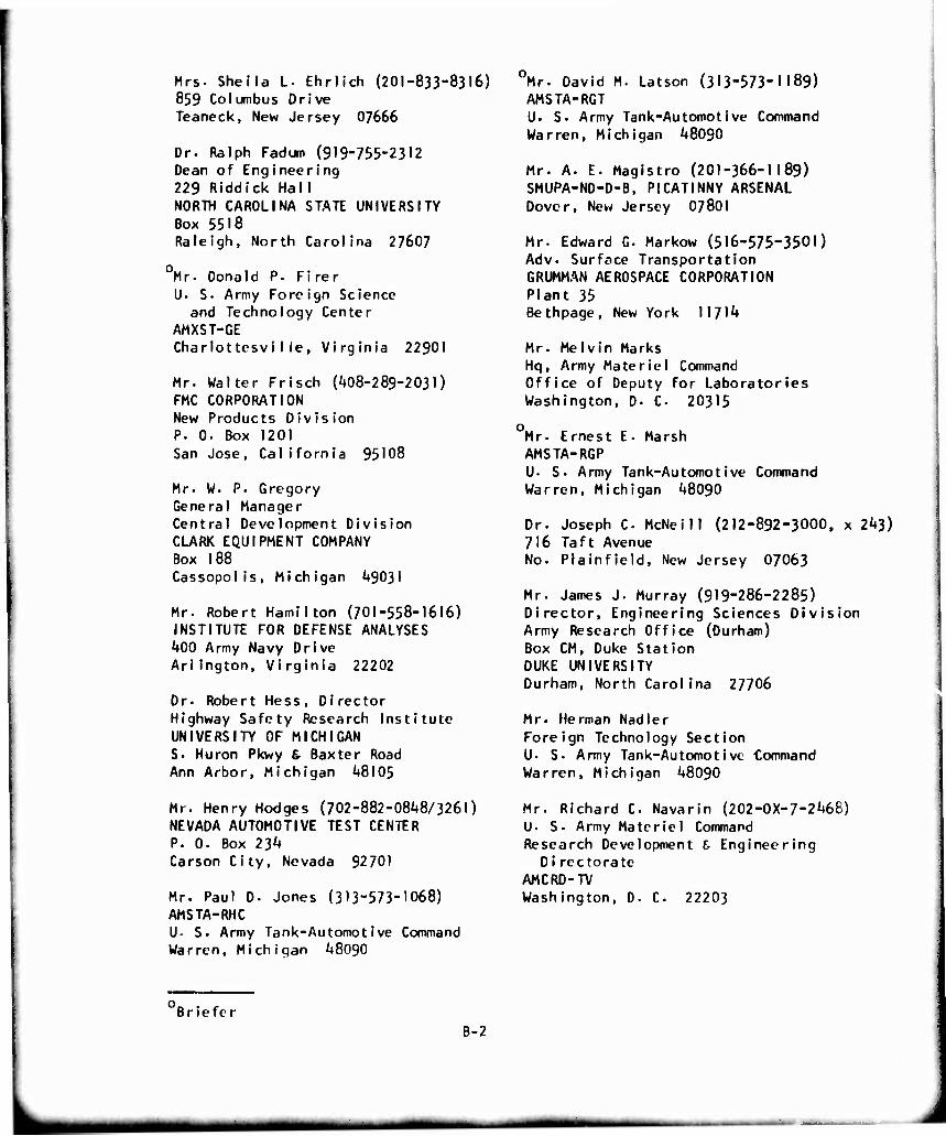
Mrs. Sheila L. Ehrlich (201-833-8316) 859 Columbus Drive Teaneck, New Jersey 07666
Dr. Ralph Fadum (919-755-2312 Dean of Engineering 229 Riddick Hall NORTH CAROLINA STATE UNIVERSITY Box 5518 Raleigh, North Carolina 27607
Mr. Donald P. Firer L). S. Army Foreign Science
and Technology Center AMXST-GE CharlottesviI(e, Virginia 22901
Mr. Walter Frisch (/t08-289-203l) FMC CORPORATION New Products Division P. 0. Box 1201 San Jose, California 95108
Mr. W. P. Gregory General Manager Central Development Division CLARK EQUIPMENT COMPANY Box 188 Cassopolis, Michigan ^9031
Mr. Robert Hamilton (701-558-1616) INSTITUTE FOR DEFENSE ANALYSES
^♦00 Army Navy Drive Arlington, Virginia 22202
Dr. Robert Hess, Director Highway Safety Research Institute UNIVERSITY OF MICHIGAN S. Huron Pkwy & Baxter Road Ann Arbor, Michigan ^8105
Mr. Henry Hodges (702-882-0848/3261) NEVADA AUTOMOTIVE TEST CENTER P. 0. Box 234 Carson City, Nevada 92701
Mr. Paul D. Jones (313-573-1068) AMSTA-RHC U. S. Army Tank-Automot i ve Command Warren, Michigan 48090
Mr. David M. Latson (313-573-1189) AMSTA-RGT U. S. Army Tank-Automotive Command Warren, Michigan 48090
Mr. A. E. Magistro (201-366-1 189) SMUPA-ND-D-B, PICATINNY ARSENAL Dover, New Jersey 07801
Mr. Edward G. Markow (516-575-3501) Adv. Surface Transportation GRUMMAN AEROSPACE CORPORATION Plant 35 Bethpage, New York 11714
Mr. Melvin Marks Hq, Army Materiel Command Office of Deputy for Laboratories Washington, D. C 20315
o Mr. Ernest E. Marsh AMSTA-RGP U. S. Army Tank-Automotive Command Warren, Michigan 48090
Dr. Joseph C McNeill (212-892-3000, x 243) 716 Taft Avenue No. Plainfield, New Jersey 07063
Mr. James J. Murray (919-286-2285) Director, Engineering Sciences Division Army Research Office (Durham) Box CM, Duke Station DUKE UNIVERSITY Durham, North Carolina 27706
Mr. Herman Nadler Foreign Technology Section U. S. Army Tank-Automotive Command Warren, Michigan 48090
Mr. Richard C Navarin (202-0X-7-2468) U. S. Army Materiel Command Research Development 6 Engineering
Di recto rate AMCRD-TV Washington, D. C 22203
Briefer B-2
mm mat
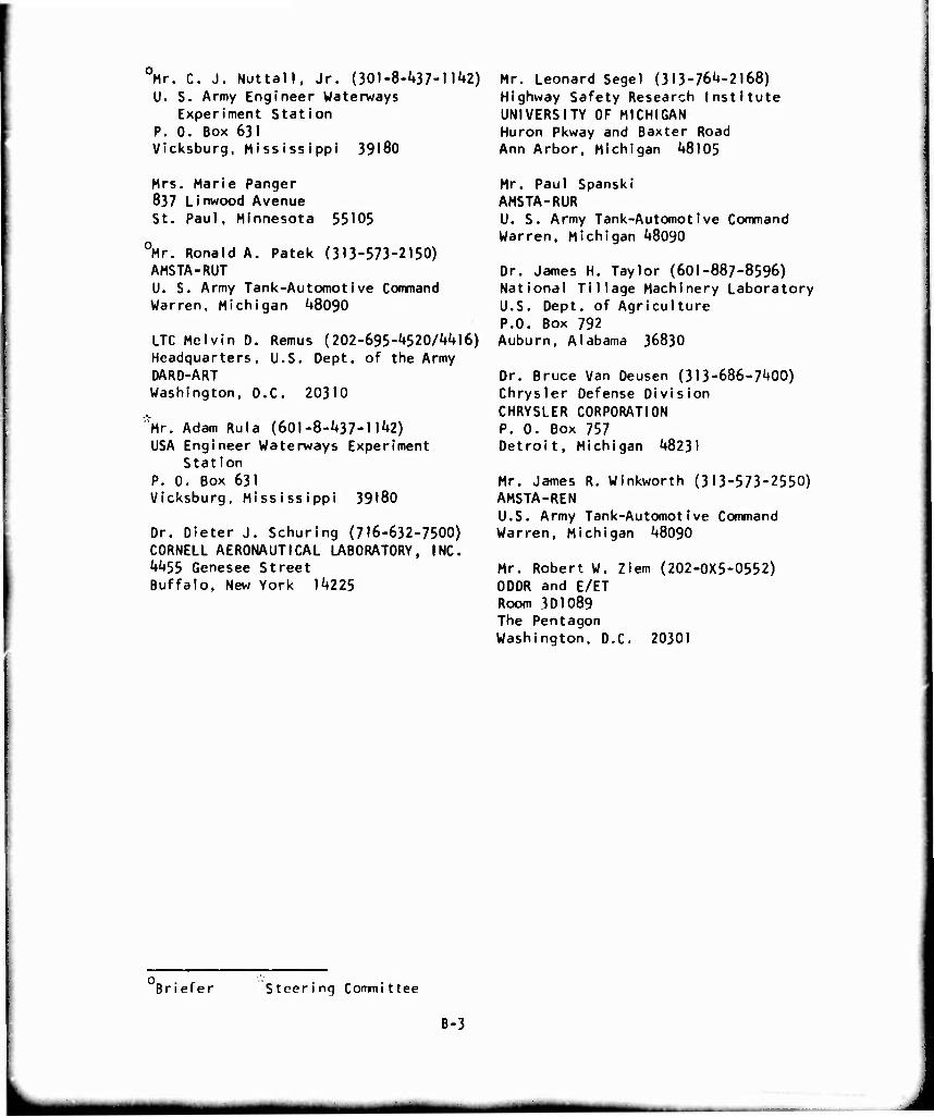
Mr. C. J. Nuttall, Jr. (301-8-U37-I l^) U. S. Army Engineer Waterways
Experiment Station P. 0. Box 631 Vicksburg, Mississippi 39180
Mrs. Marie Panger 837 Linwood Avenue St. Paul, Minnesota 55105
0Mr. Ronald A. Patek (313-573-2150) AMSTA-RUT U. S. Army Tank-Automotive Command Warren, Michigan ^8090
LTC Melvin D. Remus (202-695-'+520/Mil6) Headquarters, U.S. Dept. of the Army DARD-ART Washington, D.C. 20310
"'Mr. Adam Rula (601-8-437-11^2) USA Engineer Waterways Experiment
Station P. 0. Box 631 Vicksburg, Mississippi 39180
Dr. Dieter J. Schuring (716-632-7500) CORNELL AERONAUTICAL LABORATORY, INC. Mt55 Genesee Street Buffalo, New York 1^225
Mr. Leonard Segel (313-764-2168) Highway Safety Research Institute UNIVERSITY OF MICHIGAN Huron Pkway and Baxter Road Ann Arbor, Michigan ^8105
Mr. Paul Spanski AMSTA-RUR U. S. Army Tank-Automotive Command Warren, Michigan ^8090
Dr. James H. Taylor (601-887-8596) National Tillage Machinery Laboratory U.S. Dept. of Agriculture P.O. Box 792 Auburn, Alabama 36830
Dr. Bruce Van Deusen (3I3-686-7/+00) Chrysler Defense Division CHRYSLER CORPORATION P. 0. Box 757 Detroit, Michigan 48231
Mr. James R. Winkworth (313-573-2550) AMSTA-REN U.S. Army Tank-Automotive Command Warren, Michigan 48090
Mr. Robert W. Ziem (202-0X5-0552) 0DDR and E/ET Room 3OIO89 The Pentagon Washington, D.C. 20301
Briefer Steering Committee
B-3
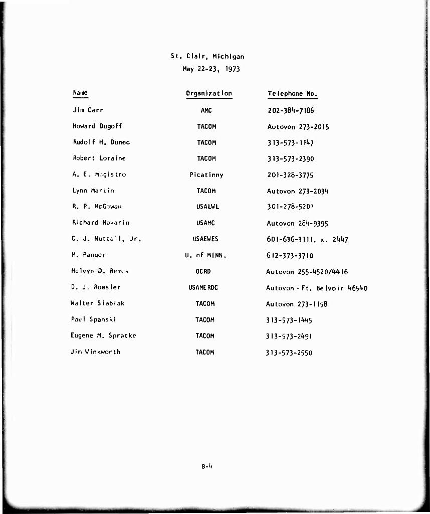
St. Clalr, Michigan
May 22-23. 1973
Name OrganizatIon Telephone No.
Jim Carr AMC 202-384-7186
Howard Dugoff TACOM Autovon 273-2015
Rudolf H. Dunec TACOM 3 13-573-M^
Robert Loralne TACOM 313-573-2390
A. E, M,.qistro Picatlnny 201-328-3775
Lynn Manin TACOM Autovon 273-203^
R. P. McGowan USALWL 301-278-5201
Richard Nävarin USAMC Autovon 264-9395
C. J. Nuttal1, Jr. USAEWES 601-636-3111, x. 2447
M. Panger U. of MINN. 612-373-3710
Melvyn D. Remcs OCRD Autovon 255-4520/4416
D. J. Roesler USAMERDC Autovon-Ft. Belvoir 46540
Walter Slabiak TACOM Autovon 273-1158
Paul Spanski TACOM 313-573-1445
Eugene M. Spralkc TACOM 313-573-2491
Jim Winkworth TACOM 313-573-2550
B-^
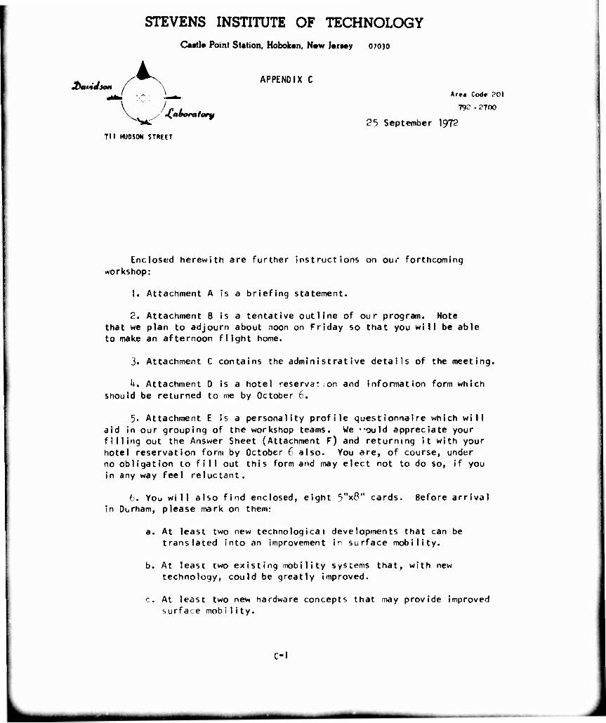
STEVENS INSTITUTE OF TECHNOLOGY
Castle Point Station, Hoboken, N«w Jorwy 07030
jbavidion i.
• •{aooratory
APPENDIX C
Are* Code ?0I
79- - ^700
25 September \$J2
711 HUDSON STREFT
Enclosed herewith are further instructions on our forthcoming workshop:
1. Attachment A is a briefing statement.
2. Attachment B is a tentative outline of our program. Note that we plan to adjourn about noon on Friday so that you will be able to make an afternoon flight home.
3. Attachment C contains the administrative details of the meeting.
h. Attachment D is a hotel reservat.on and information form which should be returned to me by October 6.
5. Attachment E is a personality profile questionnaire which will aid in our grouping of the workshop teams. We 'ould appreciate your filling out the Answer Sheet (Attachment F) and returning it with your hotel reservation form by October 6 also. You are, of course, under no obligation to fill out this form and may elect not to do so, if you in any way feel reluctant.
6. You will also find enclosed, eight 5"x8" cards. Before arrival in Durham, please mark on them:
a. At least two new technological developments that can be translated into an improvement in surface mobility.
b. At least two existing mobility systems that, with new technology, could be greatly improved.
c. At least two new hardware concepts that may provide improved surface mob i1i ty.
c-i
STEVENS INSTITUTE OF TECHNOLOGY DAVIDSON LABORATORY CASTLE POINT STATION HOBOKEN. NEW JERSEY
7. Under separate cover, you will be receiving a report discussing the state-of-the-art on ground mobility. Bring it with you to the workshop and, if you have a chance, look it over before arriving.
I am looking forward to seeing you in Durham and to a most enjoyable and useful workshop.
Very truly yours,
I. Robert Ehrlich
I RE:dp
C-2
MM
ATTACHMENT A
WORKSHOP TECHNICAL BRIEFING
1. Objectives;
To review the state-of-the-art of qround mobility and to identify, ,
conceive, and examine possible concepts and approaches for materially /
increasing the Army's ground mobility for the period I98O-I99O and beyond. /
The purpose of this group Is to develop ideas, not necessarily ^
workable concepts. If the ideas «ire innovative and show promise, then
research can be initiated to develop them into concepts.
2. Scope;
The scope of the effort will be limited to ground vehicle mobility
for off-road cross-country and unimproved roads and trails. It will be
oriented towar) combat (fighting) and tactical vehicle concepts. Important
to mobility but excluded from this effort are:
(I) Amphibious Operations
(?) Containerization
(3) Other Non-Vehicle Logistics Systems: Pipelines - fixed rail - mono-rails - conveyor systems - tramways
The meeting will identify present mobility needs and problems,
fruitful research areas and innovative ideas that have the greatest
potential for improvements in off-road ground mobility for the future.
The basic tools of mobility and mobile warfare are aircraft, combat
and tactical vehicles, general and special purpose vehicles, pipelines,
amphibious lighters and barges, and ships. The Workshop will consider
those combat and tactical vehicles which maintain contact with the
surface either through load-bearing mecnanical contact or air cushion.
C-3
mmm^m
3- Discussion:
Mobility iwans '"any things to many people- Each person sees it in the
light of his own k'l0W'edge and experience- The te rm mob i I i ty is defined in
AR-3IO-25 as: "A flua' i ty or capabi I i ty of mi I i tary forces wh i ch permi ts
them to move from p'ace to place while retaining the ability to fulfill their
primary mission." The same document defines mobile warfare as: "Warfare of
movement in which t^e opposing sides seek to seize and hold the initiative by
use of maneuver, organization of fire and utilization of terrain."
For the purposes of this Workshop, a combat vehicle is defined as: "A
vehicle with or wit'^^t armor, designed for a specific fighting function."
A tactical vehicle 's defined as: "A veh icle wi th mi I i tary characteristics
designed primarily for use by forces in the field in direct connection with,
or support of, combat or tactical operations." The emphasis will be on off-
road cross-country operations.
The trend in recer>t years in the field of ground mobility has been toward
product improvement '-hrough a program of modification and modernization. This
approach is perhaps appropriate from a short-range viewpoint; however, the
fact that most of the Army's present fleet was built with I9SO-60 state-of-
the-art and will be 20-3O years old by I98O suggests that advances in
technology may make feasible new and improved systems that will provide the
U.S. combat soldier of the future a tactical advantage.
The task of gePerating new innovative ideas in the ground mobility field
is particularly cha"eriging- There are experts in the field wh. claim that
there is little chance of something "new under the sun" and that bra instorming
sessions such as th's one can only be "fruitless" and "unprofitable." The
challenge for us is to examine the technology base and to prognosticate the
future. If there 3re no new ideas then, perhaps we can confirm the above
claims and direct a" our resources toward product improvement. On the
other hand if new ideas do surface, we may spark a break in the stalemate.
Ideally, we should identify technical options that the Army should consider
in developing its fu,:üre ground mobility research and development programs-
C-^
mmtmm^^m^^mmm
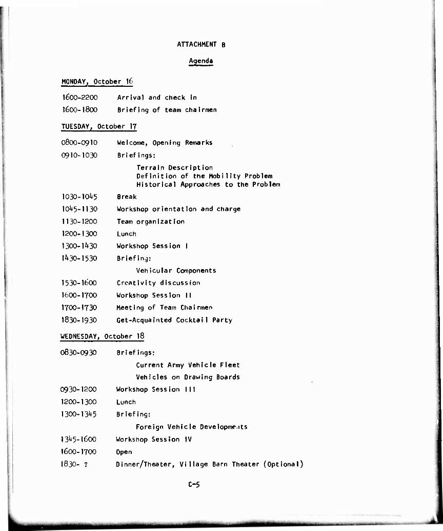
ATTACHMENT B
Agenda
MONDAY, October 16
1600-2200 Arrival and check in
I6OO-I8OO Briefing of team chairmen
TUESDAY, October 17
O8OO-O910 Welcome, Opening Remarks
0910-1030 Briefings:
Terrain Description Definition of the Mobility Problem Historical Approaches to the Problem
1030-IOU5 Break
10^5-1130 Workshop orientation and charge
1130-1200 Team organization
1200-1300 Lunch
1300-1430 Workshop Session I
1430-1530 Briefing:
Vehicular Components
1530-1600 Creativity discussion
1600-1700 Workshop Session II
I7OO-1730 Meeting of Team Chairmen
1830-1930 Get-Acquainted Cocktail Party
WEDNESDAY, October 18
0830-0930 Briefings:
Current Army Vehicle Fleet
Vehicles on Drawing Boards
0930-1200 Workshop Session Ml
1200-1300 Lunch
1300-1345 Briefing:
Foreign Vehicle Oevelopme.its
1345-1600 Workshop Session IV
1600-1700 Open
I83O- ? Dinner/Theater, Village Barn Theater (Optional)
C-5
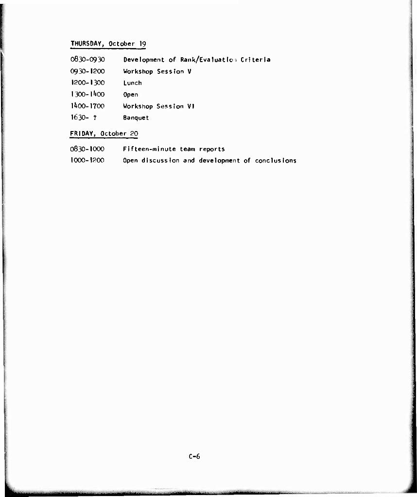
THURSDAY, October 19
0830-0930 Development of Rank/Evaluatlo , Criteria
0930-1200 Workshop Session V
1200-1300 Lunch
1300-lUoO Open
lUoO-1700 Workshop Session VI
I63O- ? Banquet
FRIDAY, October 20
O83O-1000 Fifteen-minute team reports
1000-1200 Open discussion and development of conclusions
C-6
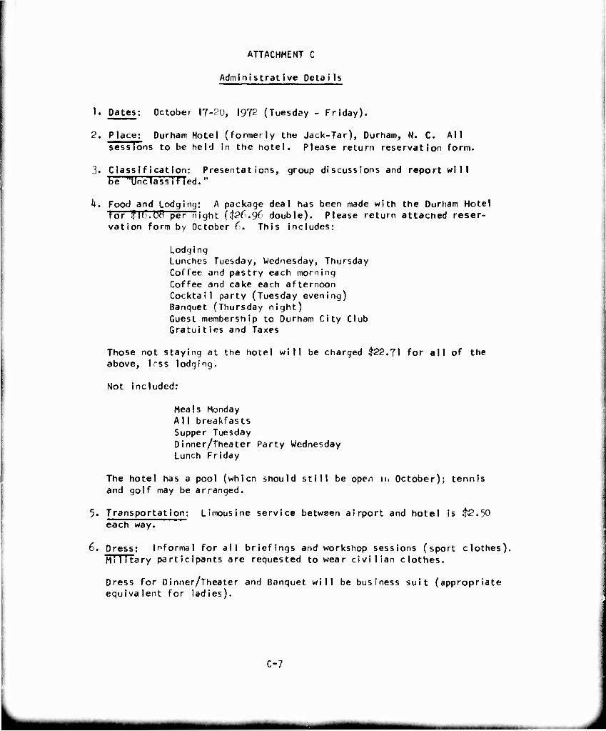
ATTACHMENT C
Administrative Details
1. Dates; October 17-20, 1972 (Tuesday - Friday).
2. Place; Durham Hotel (formerly the Jack-Tar), Durham, N. C. All sessions to be held in the notel. Please return reservation form.
3. Class Ification: Presentations, group discussions and report will be "Unclassified."
h. Food and Lodging: A package deal has been made with the Durham Hotel tor .flb.üö per night ($26.96 double). Please return attached reser- vation form by October C. This Includes:
Lodging Lunches Tuesday, Wednesday, Thursday Coffee and pastry each morning Coffee and cake each afternoon Cocktail party (Tuesday evening) Banquet (Thursday night) Guest membership to Durham City Club Gratuities and Taxes
Those not staying at the hotel will be charged .t22.7l for all of the above, 1-ss lodging.
Not included:
Meals Monday A I 1 breakfasts Supper Tuesday Dinner/Theater Party Wednesday Lunch Friday
The hotel has a pool (whlcn should still be open jn October); tennis and golf may be arranged.
5. Transportation: Limousine service between airport and hotel is $2.30 each way.
6. Dress: Informal for all briefings and workshop sessions (sport clothes). Mi 1itary participants are requested to wear civilian clothes.
Dress for Dinner/Theater and Banquet will be business suit (appropriate equivalent for ladies).
C-7
^■MH
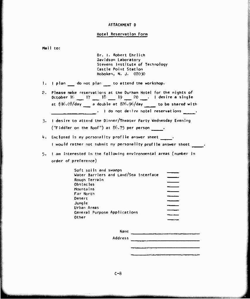
Mail to:
ATTACHMENT D
Hotel Reservation Form
Or. I. Robert Ehrlich Davidson Laboratory Stevens Institute of Technology Castle Point Station Hoboken, N. J. 07030
1. I plan do not plan to attend the workshop.
2. Please make reservations at the Durham Hotel for the nights of October 16 17 18 19 20 . I desire a single
at .tl£).08/day a double at $26.96/d«y to be shared with
. I do not de-, ire hotel reservations .
3. I desire to attend the Dinner/Theater Party Wednesday Evening
("Fiddler on the Roof") at $6.75 per person .
h. Enclosed is my personality profile answer sheet .
I would rather not submit my personality profile answer sheet
5. I am Interested in the following environmental areas (number in
order of preference)
Soft soils and swamps Water Barriers and Land/Sea Interface Rough Terrain Obstacles Mountains _^^^ Far North Desert Jungle Urban Areas General Purpose Applications Other
Name
Address
C-8
mm
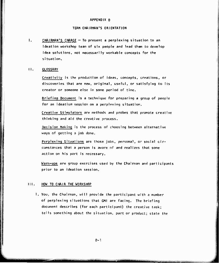
APPENDIX D
TEAM CHAIRMAN'S ORIENTATION
I. CHAIRMAN'S CHARGE - To present a perplexing situation to an
ideation workshop team of six people and lead them to develop
idea solutions, not necessarily workable concepts for the
si tuation.
II. GLOSSARY
Creativi ty is the production of ideas, concepts, creations, or
discoveries that are new, original, useful, or satisfying to its
creator or someone else in some period of time.
Briefing Document is a technique for preparing a group of people
for an ideation session on a perplexing situation.
Creative Stimulators are methods and probes that promote creative
thinking and aid the creative process.
Decision Making is the process of choosing between alternative
ways of getting a job done.
Perplexing Situations are those jobs, personal, or social cir-
cumstances that a person is aware of and realizes that some
action on his part is necessary.
Warm-ups are group exercises used by the Chairman and participants
prior to an ideation session.
Ill . HOW TO CHAIR THE WORKSHOP
I. You, the Chairman, will provide the participant with a number
of perplexing situations that GMI are facing. The briefing
document describes (for each participant) the creative task;
tells something about the situation, part or product; state the
D-1
mmmm mm
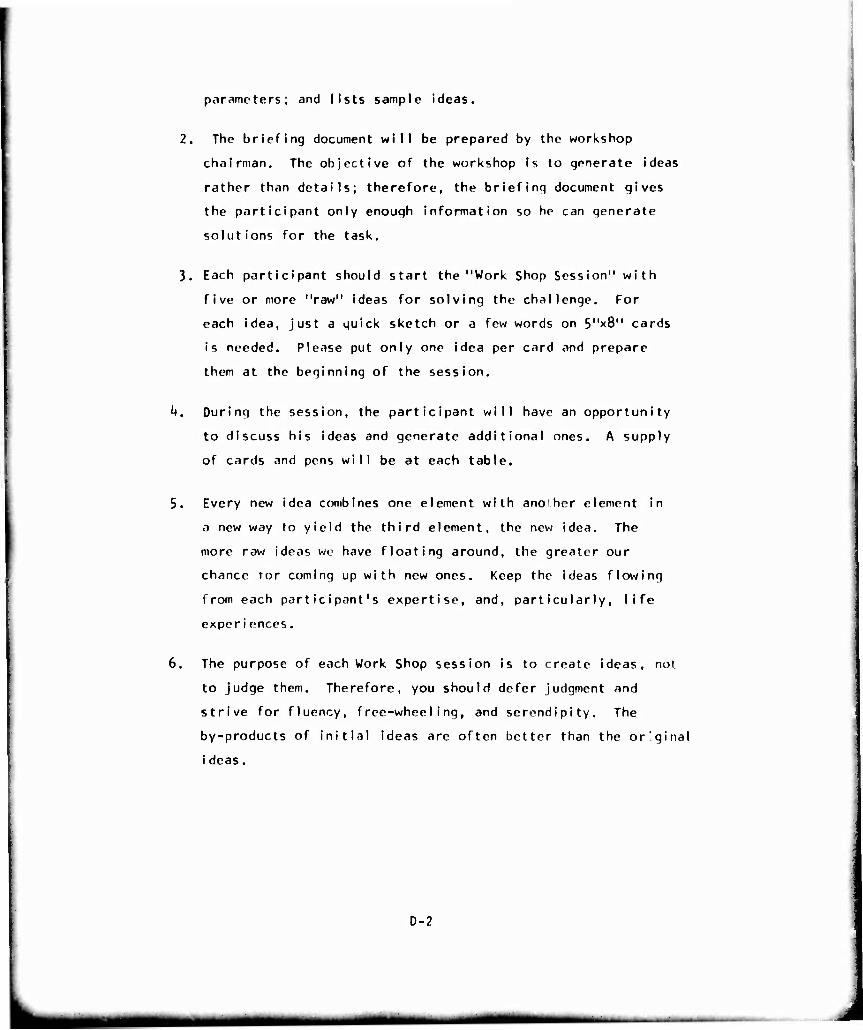
parameters; and lists sample ideas.
2. The briefing document will be prepared by the workshop
chairman. The objective of the workshop is to generate ideas
rather than details; therefore, the briefing document gives
the participant only enough information so he can generate
solutions for the task.
3. Each participant should start the "Work Shop Session" with
five or more "raw" ideas for solving the challenge. For
each idea, just a quick sketch or a few words on S'^S" cards
is needed. Please put only one idea per card and prepare
them at the beginning of the session.
k. During the session, the participant will have an opportunity
to discuss his ideas and generate additional ones. A supply
of cards and pens will be at each table.
5. Every new idea combines one element with another element in
a new way to yield the third element, the new idea. The
more raw ideas we have floating around, the greater our
chance tor coming up with new ones. Keep the ideas flowing
from each participant's expertise, and, particularly, life
experiences.
6. The purpose of each Work Shop session is to create ideas, not
to judge them. Therefore, you should defer judgment and
strive for fluency, free-wheeling, and serendipity. The
by-products of initial ideas are often better than the original
i deas.
D-2
7. The objective of each "Work Shop" session is to produce a
quantity of idejs, not just a few carefully considered ones.
Our objective is 300 ideas per session. Quantity brings quaHty.
8. In the Work Shop sessions, insist that each new idea that comes
up be put on a card with a quick sketch and/or a few words.
Our purpose is not to create a work of art or an engineering
marvel. We just want the participant to communicate the es-
sense of his idea. Each card should be dated, initialed, and
put in the center of the table. Give each idea as little
engineering thought as possible.
9. Idea concepts are what we are looking for, so move along by
free-wheeling and generating related ideas. Get the ideas Into
the hopper, but have the participant express them verbally to
the group.
10. Keep each participant on the idea being generated by the work
shop group. Each contributions will be much more valuable if
the group could explore them. The chairman will lead the way.
11. Keep the group loose. Try smile breaks every 30 minutes.
12. Relax and enjoy yourselves. Creating ideas can be fun for
both the chairmand and participants.
IV. THINGS TO WATCH OUT FOR
1. Check all room conditions for the comfort of participants.
2. Repeat the instructions prior to each ideation session.
Remind everyone that the objective is idea solsutions to
the perplexing situation—not critical comments.
3- Be certain each idea is written on a 5" x 8" card that is dated,
initialed, and immediately turned in.
h. Set the expected output of ideas for each session.
5. Start on time and end on time.
6. Keep the session moving by calling on each person to participate
In a clockwise rotation.
7. If idea production lags, change the creative stimulator or technique,
0-3
•MM mm
V. PROBLEM SOLVING MODEL AND THC PHASES THE CONFERENCE WILL COVER.
SEE EXHIBIT A AND B.
VI. CREATIVITY LECTURE (slides)
a. What is it?
b. What stifles creativity?
c. Whit enhances creativity?
d. Group effort for plannsd innovation.
VII. CREATIVE STIMULATORS AND TECHNIQUES (vary these during the
workshop session)
I. Rules of Deferred Judgement
a. CRITICISM IS RULED OUT: Judgement is suspended until a
latter screening or evaluation session. Allowing yourself
to be critical at the same time you are being creative is
like trying to get hot and cold water from one faucet at
the same time. Ideas aren't hot enough; criticism isn't
cold enough. Results are tepid.
b. FREE WHEELING IS WELCOMED: The wilder the ideas, the better.
Even off-beat, impractical suggestions may "trigger" in other
panel members practical suggestions which might not otherwise
occur to them.
c. QUANTITY IS WANTED: The greater the number of ideas, the
greater likelihood of winner;. It is easier to pare down
a long list of ideas than puff up a short list.
d. COMBINATION AND IMPROVEMENT ARE SOUGHT: In addition to con-
tributing ideas of their own, panel members should suggest
how suggestions by others can be turned into better ideas
or how two or nore ideas could be combined into a still
better idea.
0-^4
mm
2. Laws of Association (use questions to show:)
a. Contrast (comparison, show unlikcness, compare by
observing differences).
b. Contiguity (close proximity).
c. Similarity.
3. Idea-Spurring Questions - Use these to concentrate on a
particular idea.
PUT TO OTHER USES? New ways to use as Is? Other uses If
modified?
ADAPT? What else is like this? What other Ideas does
this suggest?
MODIFY? Change meaning, color, motion, sould odor,
taste, form, shape? Other changes?
MAGNIFY? What to add? Greater frequency? Stronger?
Larger? Plus ingredient? Multiply?
MINIFY What to subtrr.ct? Eliminate? Smaller? Lighter?
Slower? Split up? Less frequent?
SUBSTITUTE? Who else instead? What else instead? Other
place? Other time?
REARRANGE? Other layout? Other sequence? Change pace?
REVERSE? Opposites? Turn it backward? Turn it upside down?
Turn It Inside out?
COMBINE? How about a blend, an assortment? Combine purposes?
Combine Ideas?
D-5
mmmtm ' '" llWHW II»IHJ»IIJJ
A. FURTHER IPEA-SPURRING QUESTIONS
IDEA NEEDLERS
How much of this is the result of custom, tradition, or opinions?
Why does it have this shape?
How would I dcbign it if I had to build It in my home workshop?
What if this were turned inside out? reversed? upside down?
What if this wore larger? higher? longer? wider? thicker?
lower?
What else can it be made to do?
What other power would work better?
Where else can this be done?
What If the order were changed?
Suppose this were left out?
How can it appeal to the senses?
How about extra value?
Can this be multiplied?
What if this were blown up?
What if this were carried to extremes?
How can this be made more compact?
Would this be better symmetrical or asymmetrical?
In what form could this be?
Liquid, oowdc-. paste, or solid? Rod, Vjbe, triangle, cube or sphere?
Can motion be added to it?
Will it be better striding still?
What other layout might be better?
Cc cause and effect be reversed? Is one possibly the other?
Should iL be put on the other end or in the middle?
Should it slide instead of rotate?
0-6
Demonstrate or describe by what It fsn't.
Has a search been made of the patent literature? trade
Journals?
Could a vendor supply this for less?
How could this be made easier to use?
Can i t be made safer?
How could this be changed for quicker assembly?
What other mater id Is would do this job?
What Is similar to this but costs less? Why?
What If It were made lighter or faster?
What motion or power is wasted?
Could the package be used for something afterwards?
If all specifications could be forgotten, how else could
the basic function be accomplished?
Could these be made to meet specifications?
How do noncompetitors solve problems similar to this?
0-7
5. BIONICS: ASK yourself, "How is this done in nature?"
Nature's scherte of things is revealed to those who search.
(Note: Thib technique may come into play when utilizing
analogies.)
6. REVERSE BRAINSTÜRMING: Sometimes useful prior to an ideation
session. It consists of being critical instead of suspending
judgement.
(a) List all the things wrong with the operation, process,
system, or product.
(b) Systematically take each flaw uncovered and suggest ways
of overcoming i t.
7. INSPIRED (BIG DREAM) APPROACH: A "breakthrough" approach
which sometimes leads to spectacular advancements.
(a) Think the biggest dreams or technological advances possible.
(b) Read, study, and think about every subject connected
with your big dream--and do so regularly, persistently,
continually.
(c) Drop down a dream or so, then engineer your dream into
reali ty.
The objective is to make the greatest possible achievement
for human benefi t.
8. ATTRIBUTE LISTING: A technique used principally for improv-
ing tangible things.
(a) Choose some object to Improve.
(b) List the parts of the object.
(c) List the essential, basic qualities, features, or
attributes of the object and its parts.
(d) Systematically change or modify the attributes.
9. FORCED RELATIONSHIP: A method which attempts to force association.
(a) Isolate the elements of the problem at hand.
(b) Find the relationships between/among these elements
(similarities, differences, analogies, cause and effect).
D-8
(c) Record rhe relationships in organized fashion.
(d) Analyze the record of relationships to find the patterns
(or basic ideas) present. Dtvelop new ideas from these
pat terns.
VIM. CREATIVITY STIFFLEftS
I. Killer Phrases. Be low is a list of some of the killer phrases.
You know thcin well; everyone does who has ever attended a meeting, but
read the list over carefully. You will hear echoes from wasted confer-
ences, and you will know what to avoid in the future. In an ideation
session, killer phrases arc strictly rule-' out. In fact, place a bell
in the center of the table; whenever a killer phrase pops up, the bell
should be rung by the nearest person. Here they are:
We've never done it that way before
11 won't work
We haven'r the time
We haven't the manpower
It's not in the budget
We're not ready for it yet
All right in theory, but can you put it Into practice?
Too academi c
What will the customers think?
Somebody would have suggested it before if it were any good
Too modern
Too old-fashioned
Let's discuss it bome Uher time
You don't understand our problem
We're too small for that
We're too big for that , etc., etc., etc.
2. Killer Glances. Beside the killer phrase, you have to ring
the bell on the killer glance and the man who is disturbed by repetition.
Repeating an idea may spart a new chain reaction--so encourage it.
3. Apologetic Phrases (Self-Killer Phrase). A twin brother to
the killer nhrase is the apologetic phrase you often use to give a deadly
introduction to your own idea. In an ideat ion session it's outlawed too,
but don't ring the bell. Notice how these killers disappear as you cul-
tivate a creative atmosphere receptive to new ideas.
0-9
—-— ■'—
^
R-l?!1*
This may not be applicable but
While we have only made a few preliminary tests....
This may not work, but
This approach is screwy, but
It isn't clear that we need this, but
I don't know if the money can be appropriated, but.
It might be a dead end, but
Would it hurt if we did
Do you suppose it would be possible to
It may sound hair-brained, but
It may take a long time, but
I don't know just what you want, but
You probably have ideas about this too, but
You aren't going to like this, but
This is contrary to policy, but
This may not be the right time, but
This idea seems useless, but
0-10
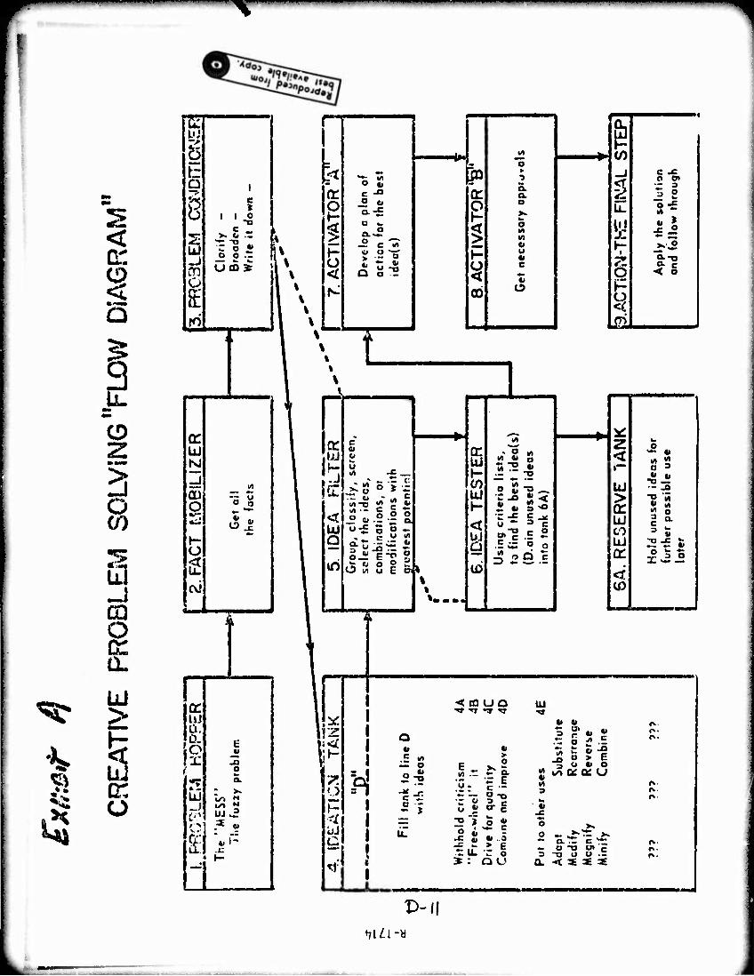
^
^
<
g Q
3 mm
ID
o en
CO o a. ÜJ
o
g b
8 S UJ -j
o
I c I
c ^ >. b ..
-2 S • z
(T ÜJ 1*0
CU O
cvi
r
cr UJ Ü. 0. o X 5
UJ
i
7"
o
UJ .^
! I 6 M CO _ ^ O
*t t; w Ja »
2 c -c o o>
rr o „ c -a a: a
a. 3 S
g g a >• U-
-. t
§ a-- 5 a M M Ö
5 <
t- O u i e «j
i
O Ap
ply
an
d <c
N 00 O
^ Lai
t
-J
c « II
»: 8 5 > I " «• S B «. S " o o o
w-£ o o - . c u ^
o-ET 0 •~ fi n O
a S S E
«•••.
~ 0 in n m a
-•^ S< U •" 3 C r»"13 C 0
.5^ o o
i3! .5 *> — a 2-S
5 J
< £0 UQ ■»» ■»r •» TT
> c o
- - I E .y: c •= ♦. — a ■« ~ ? 2. c o J »■ c 2 "> 5 j; o i~ =
-c 2: > c t: U. r o * : Q O
v: O z
< r™ O 3
«1 „ UJ -o —
— -O
> "S '5
or 5 8 UJ c Q- CO 3 s UJ 2-£ £ a: OSS x ^- — < (0
UJ
3 ? • • .t: o ^ .E n o > c 3 b «i o
2 uo o: Q£ u
3 hi 4)
— O T3 O» c 3 -O O O .r
O. < « « «
P-(( ♦7UI-«
_^^ — ^^ - ■ - .
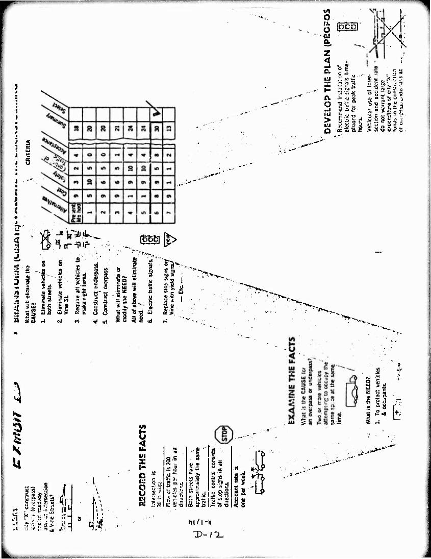
— ■ - ■ -J — —
I m
a:
o
•i
J
A 9
■ i»
33
3
13
O o a
O
>
a
s s
•I,
if ll
| ■ y
I «I JJ US
3
II s
(goej[|>
3
V ri
So
li
it <
3
y
nl
y
s-« a» M 3 * u. « t» s ot >
mfcbi' S1 ^ —y^
o?
f »1
" TT "^ >.-
0 Q
3 ?.
2 2" it! c _ »>
£ f«.
cc « ii <u
>>>. ^ rJ >:>,
I firis L
1
1 >
1 >
•' !±n'v Alt :' 2 ;?
«^
Ul
:-
u US!
§
^ '■'
■•■ f, 5
C S-5
Ul B sal
(Q ig A
I-
W irt J «^1 «5 -ra U 2 ^ " P 'S S Si
.0
t7lZl-«
K
| u
u m ci cv 2d ^8
^ i2««
?•
e .jj...
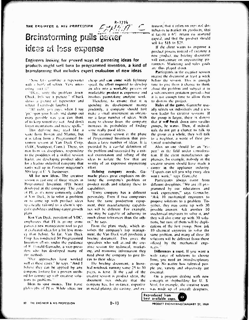
Brsinstorming puilslJeaer ideas ni loss expense Enp.inci'rs looking lor |»roved v/ays of Rarnering ideas for products miphf \^pll lurn t«» programmed Invention, a kind of bramstormmf, lh.it inrludt'S expert evaluation of new ideas
' Vn» lol • tonil'itu' .1 i\(v«riUi IUIII 1 SiH'v1 i'f sili/cr \'t'\ inli-t- cstnii: l^r^ I :'.'
"(Kr,, wnic tin' prohlcru .U'vin Chuck, Id's sic a picture." (f'huck sl»-^- .1 picture i'( tjpcwrilcr and scli/cr I vcr>hi>dy luuphs )
"All min. >i'i i'iu .. «lien I say 'go.' "|H-n Ncur heads ind dump out everj fH'Svihlc v..i\ s.iii can think nf in keep sometl'.in}! v.el And ilon'l forrel iiiLaniaimns and tnauic spell.'. "
I hi^ dm'i'Mie may read like a «tene frum Kowan and Martin, but it is taken from .1 Pro^ramntcd In- vcnlion session at Van l)\ck Corp. (\ IK , Similipori. (dnn ) There, sit nun Ifi'ttt M\ disciplines, rcspondinj; In the pri<diltn'.'s of a skilled session leader, .ire devclopinc product ideas tor ;i Ic.idinr industrial company thai ranis well up in fortune maea^inc's 5(H) larpcsl l' S businesses
Ml lor nt'w ideas. The creative session is ust one of three SML'CS in PmiV immecl Invention (I'D hem^ developed at the company The coal .1 PI. ,is it's more commonly called at Van Dyck, is to solve a problem 01 in come up with proJuct ideas spivlicallv tailored to a client's spc- ci.il c.ip.ibililic-; and lone-ranec growth plans
Kin \'jn Dyck. president of VFX'. empli i-.i/es that I'l is ei ini: coni- p.m.is a new manaeeaicni tool to pel .it evaluated idi;.s for a lot less mon- 1) lli.m before So far. Van Dyck ("orp h.is runducted 30 Programmed Invention efTorts under the euid.mce of H Donald Gamachc. a vice-presi- deni «ho has developed many of ihc methods
"Our approaches have worked well m these cases." he says "And I behexe thty can be applied by any companv liwkinc for a proven meth- od for coming: up with creative solu- tions In problems "
Idea« to save muni). The basic philosophy of PI is While ideas are
5J TM( INCtNCt» i MIS PBOrfSSION
cheap and I;MI enmc with liphtninp speed, the ellorr rr«)i>ired to develop an ulea inio a workable proeess or marketable pfixtuvf r. expensive and involves paimlalinc ar»al\tic work.
I lierefore. r>> ensme that it is spenilme its develi>pmcnt money prudently, a company should lust make a small investment in obtain- ine a laree number of ideas. With many to choose from, the comp.my increases its probability of frndinj! some really pood ideas
The creative session is the phase of Projit,mimed Invention that pro- duces a larpe number of ideas It li preceded b\ a careful definition of the problem and succeeded by a crit- ical examination and siftmu of the ideas to isolate '.he few that are worthy of an expensive eninnecnnp cllorl
Defining company needs, da- mache places great emphasis on de- limnp the company's problem or product needs and relating these to capabilities
"Ivcry company has a dilTcrcnt personality. F.vcn if two companies have the same production equip- ment, their maiiufacturinp capabili- ties will be dilferenl For example, one may be capable of adherinp to much closer tolerances than the oth- er." he says
From the plant study, which in- volves the company's lop manage- ment, the Van Dyck slalf produces a briefing document. This give* ihe specialists who will atcjnd the cre- ative session the technical, market- ing, and economic information they need about the company to give fo- cus to their ideas
I he brielmp diKiimcnt. a loosc- leaf notebook runmn:: some 25 to 30 p.i.es. is terse If the ual of the creative session is prodiict ideas, ihe documenl 'nav indicate that Ihe ci.mpany has, for invtancc. experli-c in metal plating, die casting, and ex-
trusion; ihal it teles on rer'1 n.<l dis- tributors lo market ns produds, thai it tarprts a 61 relam r>\ invested capital, and thtl Ihe pnul'ict should sell for SI5 lo $25
If the client wants to improve a product process instead of creating a new product. Ihc hriefirn; docuir.en! will cimeentrutc on enpineering pa- ramcters Marketing and sales poal» are thus played down
PjKiieip.ints in the creative session receive the document at least a week before the session, I lus is enough lime to give them a chance to ihink .iliout the problem anil subject it lo a siilxonseious gestation period—but it is not enough lime to allow them to dismiss ihe project.
Rules of Ihe game. Ciamnche usu- ally selects six individuals and a ses- sion leader for creative sessions It the group is larger, there is danffr that if wHf ^reak down into smaller groups, he warns Then, if individ- uals do not get a chance to talk lo the croup as a whole, they will talk to a neighbor, a waste of their po- '.■niial contribution.
Also no one should be an "ex- pert" m Ihe field under considera- tion. If the client manufactures ap- pliances, foi example, nobody in the creative session should have made a career in the appliance industry. "Fxperls can tell you why every idea wont work." says Gamache
Participants always mine from dilfeteni disciplines. "We ate ,;ll pn- grammed by out educations and work experiences," savs Ci?mache. "Ask 10 mechanical engineers lo propose solutions to a problem To- L'elher, ihev may come up with 30 possible answers AA another 10 mechanical engineers to solve u. and they will also ome up with 30 solu- tions, but mos: of them will be dupli- cations of the lift eronp. Now ask 10 chemical engineers to solve the same problem, and many of iheir 30 solutions will be ditlerenl from-those offered by the mechanical engi- neers '
Diflerences a must. If you want a wide range of solutions lo choose from, you need an interdisciplinary eroup No matter how talented pciv pie are. variety and objectivity are essential.
On a program dealing with new cmcepls in shipbuilding for U. S Steel, f"r example, the creative team was made up of aircraft designers.
0-13
Reproduced from best available copy.
MO0UCT fNClMrtBINC/jANUAlY 77. l»4»
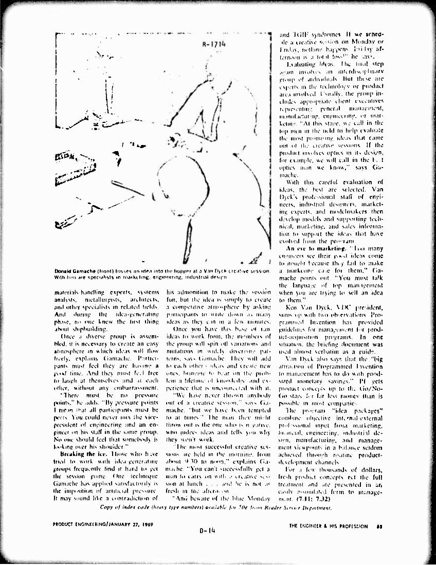
m
' •»^
/
ii/.
Oon«kl Ctmache ((ront) tosses .in irtPfl into the hopper al a V.m tl>cl> trc.itivc session With Mini »it specialists in inafKitint;. •ngtnetfing, ifulustti.il (tovpn
mulcrinls h.mdling cx^x-rts. *v<>tcnis his admnniliiin lo make lK- icssicm anaKsis, mctallurpisls, artliilcvls, fun. hut the iilc.i !>. simply to create ami iMhor s(vi.idlisis in rcl.iiiil tn-UN a compel it ivc atmnsplieie by n^kint; Ami iliiriii)' the idca-peneraltne p.irtieipanls to write ilovwi .l^ ma;i) ph.ivc. ni> i'iie knew the (irsi thing uleas as the) can in a few iniiiiiUs.
Uncc you have IIMS H.AO of taw ideas to work from, ihj nvmbers of the I'foup will spin oil variations and niulalions in wuUI) üivereme pat- terns, vi\>. (I.HU.KIIC liiev will .ulj ii> each dihrr •• ulias and create new lines. Snnei'U' I«' h. ar nn llie pioh- leni a lifetuiK i'l knowk*l;.v aiul es- penenee that is uneontivil.'tl with ii.
"Wi- have never thrown .in\iH>ilv out of a ireadu' SCSMHII," S,I\S fia-
•iKoul shiplniililinj!. Once •" diverse proup is assem-
Wed. it is necessary lo create an easy M'nosphere in which ideas will Mow freely, explains (iamaclie. Partici- pants niust feel they are havms* a J'MKI lime. And llicy niust fe.l free lo latieh at themselves and o etch filier, withotii any einharrassmeni.
"1 here must be no pressure points." he add». "Hy pressure points I mean i'at all parlictpants must be mache, "bul we have Ken templed peers Vou could never mix ;he vice- president of cneinrerint! and an en- gineer on his stalf in the same j'roup. No one should feel lliat somelvHlv i> |«»>kinc mer his shouider "
Briukint» Ihr ice. Ihosc who hsve tried lo work with idea eeneraiine (.•roups frequently lind u hard to ce' maihc. "Vou can't kuccesvfiillv the session ptiint One technique man to i.irrv nn will
to al limes" I he man ihev mi; lit throw out is the one who i> 11 e.iiive. who judees ideas and tells jou why Ihey won't wnrk.
Ihe ui'ist successful creative ses- sii'if. ire held in the mornini'. from alwiiii i> M) io ni>"n." explains da-
pcl a >. ii. aloe sv v-
(iamaehe has applied satisfactorily is sum at luncli . a'u! he is not a« the impi'Siiion of arlilicial pressure fresh in the afterui on It may sound hVc a conlradiclitm of "And beware of the blue Monday
Copy of imlrt coJr (lifuvf lyff numhen) OfiiHubti /.i/ ?(W ('..»i HiaJfr .Sinne litpailn
and I(ill; jyni'romcJ II we irhco- de a creative SC-MOO on Mnnday or lrul.iv, niill'.ini' h.ij pens J'iliy :if- lern.'nn is a total loss'" he ,av>.
Lialualiriß Wcas, Hie Imal "ilep ai'.un invitlves an intcrdisuplinarv eroup of individuals lint line are experts in the tcchnnioev or producl aiea involved tMiillv. Ihe j-roup in- i hides appropriate ihent executives reprC'entini; prneral manarmcit, mamifacturnp, en|;inecrini', or loar- kelinv "Al llus slaee, we call in the top men in the lield lo help evaluate the most prunusinii ideas that came out nl ill. creative sessions If the piodtid mvulves oplns in its design, for example, we will call in Ihe b. t optics in.in we know," says CJa- maehc.
With this careful evaluation of ideas, the best are selected. Van Dyek's prole-sioual stall of enei- neeis, industrial desirncrs, niaiket- ini; experts, and modelm.tkcrs then develop models and supporlinp tech- nical, marketing, and s.iles informa- tion to sup)'ii! Ihe ideas that have evolved from the pro'.'ram
An eve lo marketing. "I«HI many eiv.'ineeis see their p.»d ideas come In noiielii because llu y fad lo make a markciim* c.ie for them," fia- machc points out. "Vou must la'k Ihe lanpKK-e nf top man ii'nneiit when )ou are trjlnp lo sell an idea to lliem."
Ken Van Dyck, \\K~ president, sums up wilh two iib-.ervalions I'ro- frammetl Invention has provided piiidelni.v for management l-u prnd- iieI-ae(|iiisiiion proerams. In one situation, the bnefini: document was used almost verbalim as a cuid?.
X'.in Dyck also say, thai the "big allraioon o( I'ri'erammed Iivention to manaeemenl has to do wiih pood- si/cd monetary savings," IM pets pioiiuil concepis up to til. Cio/No- (io slaee fi-r far less moncv than is possible in iiuist companic
The |"o;r,im "idea paekapes" combine objective internal-external prof.'ssional input from marketing, III.HUI.II, enpinccrinp. inittistrinl de- sign, mannfaciurinp., and manage- ment viiwpoiiiis in a balance seldom achieved throuph ro.ninc product- dcvelopmcnl channels
lror a few thousands of dollars, fresh piodiiv.1 eoneepts eel the full treat mem and are presented in an easily assimilated fcirn to manage* m.ni 17.11: 7.32)
MOOUCT INCINtESlNG/jANUARY 37, 1969 O-l^
THE CNCINCCR t HIS PROFEUION II
—^ . -
'■ ■ '■■■ ' "^ —■■—-'■ "^ iw
R-iyi4* £&i&/r2>
\
HOW CREATIVE SESSIONS FUHCTION Miivi1 you i'vcr (»artM i|i.il>'<l in si'iall
iniproiiiiiin jMinip^, ijri'i'tnuni' ni u.iys In piny a tfnl nn hiiitn'tim ' l>i li.ivi' ymi cx- po rii'nc id tin ilfliulil "' i" i • ( ■ •• i in' .m «ml- laiifll ill Ni'lu'ini', h.tviiu; it ir n.iilialily fiij>jiofl liy SCIMU' tlsi', iiixl Ihfii, tliriMnjli ihocr inapiratioH, pr«'h»-iitint; in pv«n lll^^<, utitliiiulihh Iriik yi'Htsclt ' If HII, you know llic bouy.'iut spirit ami i'xhi uratmn P" nm-.itiiii; Hiu:h an alini;s(.|.r i c Oiasimi- all>'. ll>r nsullin,; trlraN ar-1 I ruly Hijjon- im. .-i. rr.it liiiih Ijiiitu.'h* in!.» i xif.tcii'c as a fliiifl n.'Kiilt of tin' mutual Huppori and « MI onra^ii.Kni throucl'K'if the i;roup
Ltt'.s sic luiw tn apply tlw sunic Icch- iür|ur in in^im-ii iiiL; a<'tivitifb tu rri'itlu tli« IK-W idt-ao su nrrCBsnry Inr priori1»«. A look at why luill - si' s sinn-. .1 i r sn c uiiHn- nvi' tu liiiaittnativt' .iclv» nt'ir«' may luriush Rom«- ilms 1 hi- sfss.i()r--> 1 ri'.ttr an atMiOiiptu'ri' lli.it alliiws ym; tci . .
txjjribs the problem i;< tic rally-fror frorii all rirlc HpdcificntiunA or rnnrli- tions.
Aü&umc that every ioi-a will <vork.
Si-nrch for nli a'i willn'iit r«-•! ru tiniiH.
I'irtif ip.iti1 with n competiliv«1 npirit.
Cnpltallltt! mi the mnt'ial .itirnsph« re of prairiu an'! (•ncouraui'iiu'nt.
Carry thfst' ftrunnd ruli s uvi-r into a
< rualive .WI-FMOO and yciii ran laikU- any tnuuh cnniifcn ii); problem, .Tust remem- ber (lu'Mc i' Kiniple i nies.
Hi-Hides heilig a liotii cc of ni'w nli-as, tliebe Mst.iiin;. ni'C also valuable for their sliinn laiivi.' ofl'Tt on the group and on each individual. When this effect in fnlt in a lar^c rli'(;rce, you know that ri< ativity naa had tin- best opportunity to exhibit itsflf. And if truly sun« ssud, thic Blnnul.ition will ()<• carried back In the joli. Don't rx- prrt an nvii rdialcly nsefu! id, a from every Ncnüion. Hut MI expect that a« you eontin- uc to huld thche hi-sbion» the perrcntanc of useful Ideas will increase. For your creative lali'iils ri'spniul to < xii- ihi- j'tst at do all your other abilities
After the rreative seNijion, evaluate each idoa i.ifefully. Ask yoursell »urh queutiona a«: Could »his be 1 lafi'- to work if 1 made ii smaller? Wh.il if ! ns«-fl ,1 different material? What if 1 changed in shape? Uh.it 11 I eombined thrsf two trlcaa? l"in,illy, si UM I the most proiiinn,- ideas for fnrth'-r invrst;.'I'mn and anolysli.
Remember: Your creative eflurtJ «TC
stifled when the Im-nedlate reiiponsc is either no or .1 look .1 deriflton. V.'litn this 01 i-nr»», i iiaiivity i rawlH li.n 1< into us little MIH-II, .nd old bluepnnl i, dd apprn.ii he;., and old lechniipiei* eontintie on an alwayc. I'te Iheae crt •iti«/«* «rsh.oas to break IOOHO from inhibition». KxerriRU • •inir in ..)> man on. flnve the will to N'H - ceefl. And ". Ii" knows, yon may devH.iji a pr nhut tli.il will put tin coiiipetilion to ahitme. 'I ry it'.
0-15
—- -■ - ■-innfiiDnii

—
APPENDIX E
BRIEFING DOCUMENT - TEAM 11]
Workshop Session 1
Man/Mach i ne/Env i ronment Interface
I. Statement of Perplexing Situation:
What are the possible future (1960-1990 and beyond) technological
advances which might be translated into an Improvement in vehicle mobility
from the standpoint of the vehicle man/machine/environment interface?
It. Background Information
A vehicle cannot oe operated properly without an effective man/machine/
environment interface. Poor interfaces prevent the driver from operating
his vehicle at its optimum level of performance. Tasks of this interface
ore to:
a. Provide adequate visibility to the operator of the vehicle displays
and the terrain.
b. Provide a link between the operator and the controls of the vehicle*
c. Provide feedback of driver actions.
d. Keep the temperature surrounding the crew at a comfortable level.
Improvements in the man/machine/environment interface will allow for
more efficient operation of the vehicle and the ability of the driver to
obtain the maximum from the vehicle's capabilities.
III. Basic Questions
a. What are the characteristics of a good (or bad) man/machine/environment
interface?
b. What additional influences does the m/m/e inteface have on vehicle
operation?
c. How does nature solve the m/m/e Interface problem?
E-l
—MMatea—»*-.^-. ,.*.—, fc^—^—i^a—fct—^j. lMt--. -JM.- .-. . ^^MHa^ --—-
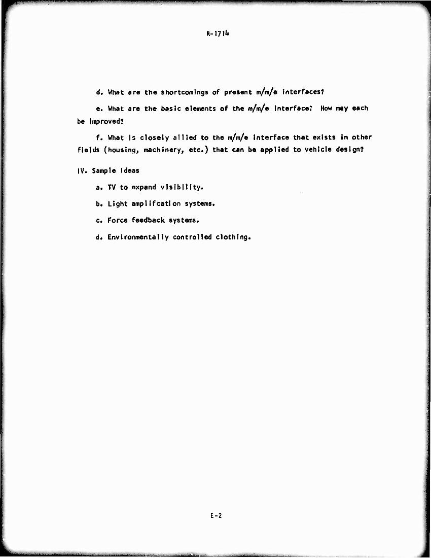
• ■■ ■'" ' I l"ll
^
R-I?^
d. What are the shortcomings of present m/m/e interfaces?
e. What are the basic elements of the m/m/e interface? How may each
be improved?
f. What is closely allied to the m/m/e interface that exists in other
fields (housing, machinery, etc.) that can be applied to vehicle design?
IV. Sample ideas
a. TV to expand visibility.
b. Light ampl if cation systems.
c. Force feedback systems.
d. Environmentally controlled clothing.
E-2
■ i■ i _.
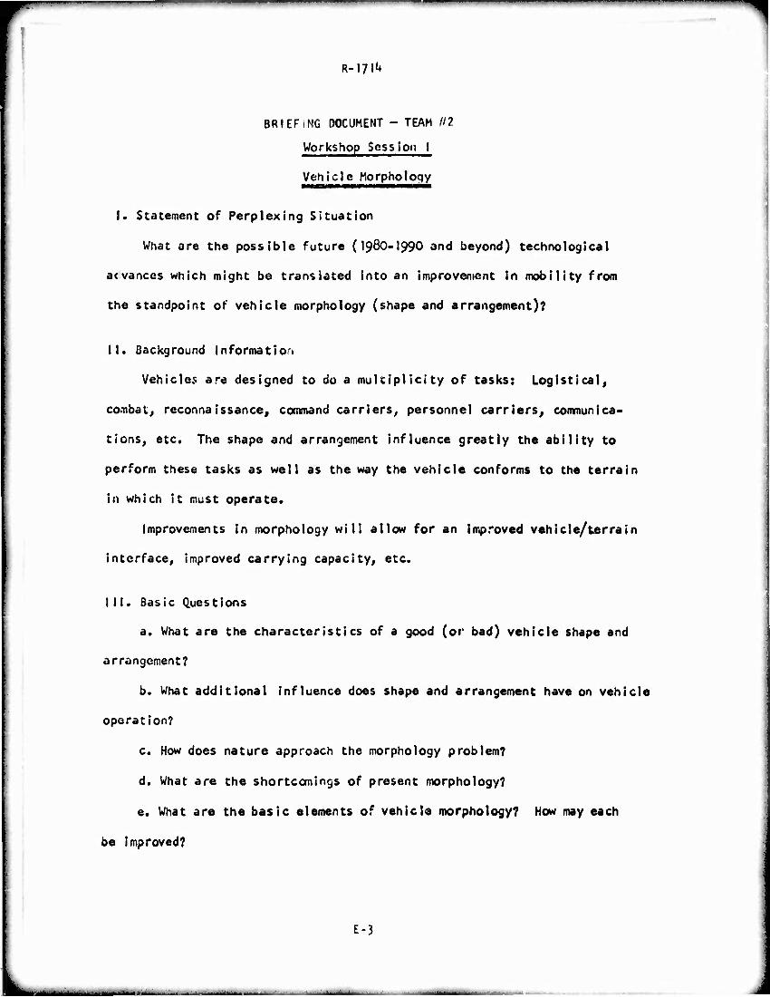
■—■
BRIEFiNG DOCUMENT - TEAM ill
Workshop ScssIon I
Vehicle Morphology
I. Statement of Perplexing Situation
What are the possible future (I98O-I99O and beyond) technological
acvances which might be translated into an improvement in mobility from
the standpoint of vehicle morphology (shape and arrangement)?
II. Background Informatioi
Vehicles are designed to do a multiplicity of tasks: Logistical,
combat, reconnaissance, command carriers^ personnel carriers, communica-
tions, etc. The shape and arrangement influence greatly the ability to
perform these tasks as well as the way the vehicle conforms to the terrain
in which it must operate.
Improvements in morphology will allow for an improved vehicle/terra in
interface, improved carrying capacity, etc.
III. Basic Questions
a. What are the characteristics of a good (or bad) vehicle shape and
arrangement?
b. What additional influence does shape and arrangement have on vehicle
operation?
c. How does nature approach the morphology problem?
d. What are the shortcomings of present morphology?
e. What are the basic elements of vehicle morphology? How may each
be improved?
E-3
-■ - ■- -■■mi 1 — ■ .. «-■. . 1 r ^
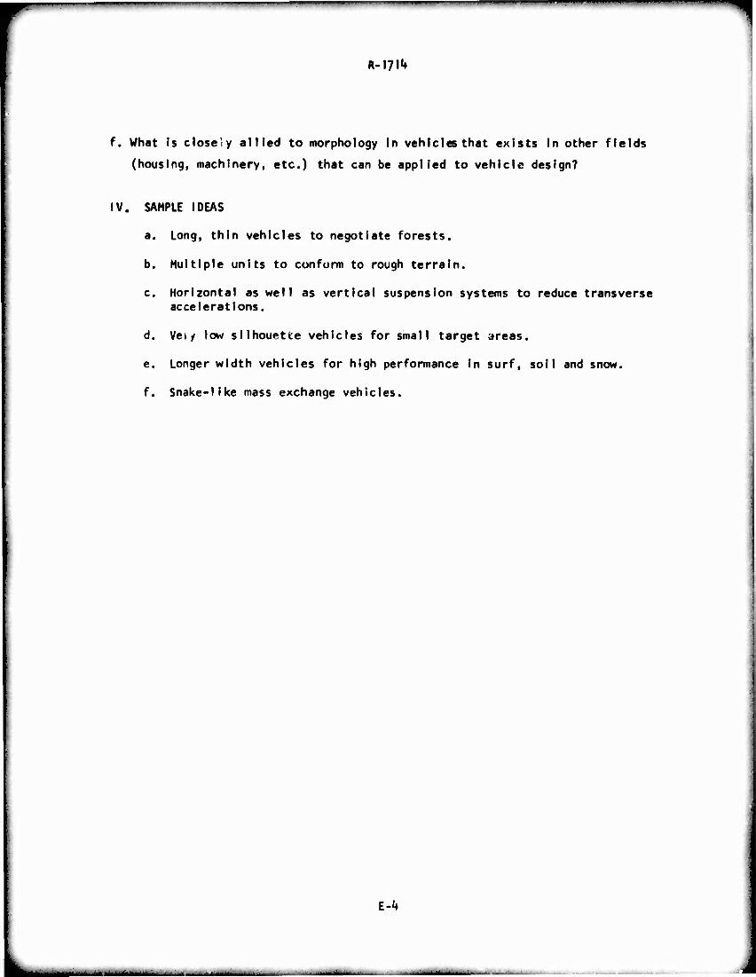
" ' ■' " "-"
R-??!*»
f. What Is close'y allied to morphology In vehicles that exists In other fields
(housing, machinery, etc.) that can be applied to vehicle design?
IV. SAMPLE IDEAS
a. Long, thin vehicles to negotiate forests.
b. Multiple units to cunfurm to rough terrain.
c. Horizontal as well as vertical suspension systems to reduce transverse accelerations.
d. Vety low silhouette vehicles for small target areas.
e. Longer width vehicles for high performance in surf, soil and snow.
f. Snake-like mass exchange vehicles.
l-k
- ■ -
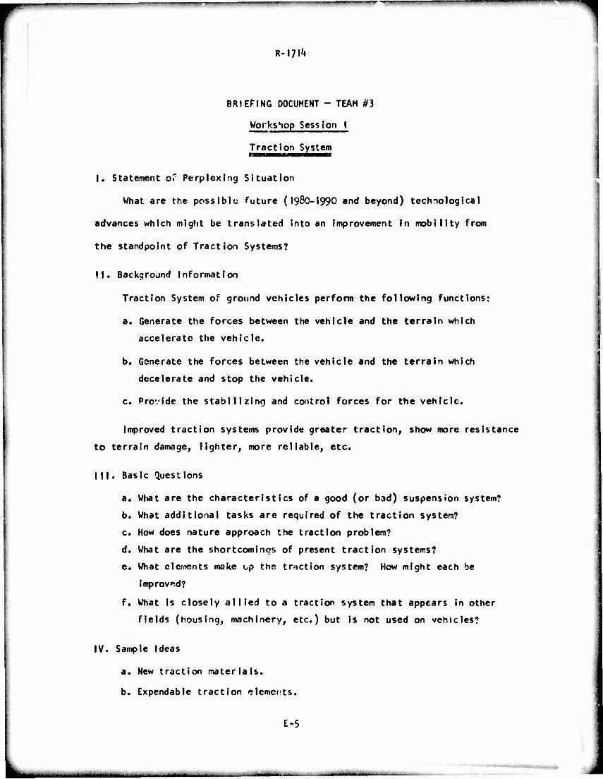
BRIEFING DOCUMENT - TEAM #3
Workshop Session I
Traction System
I. Statement of Perplexing Situation
What are the possibly future (I98O-I99O and beyond) technological
advances which might be translated into an improvement in mobility from
the standpoint of Traction Systems?
II. Background Information
Traction System of ground vehicles perform the following functions:
a. Generate the forces between the vehicle and the terrain which
accelerate the vehicle.
b. Generate the forces between the vehicle and the terrain which
decelerate and stop the vehicle.
c. Provide the stabilizing and control forces for the vehicle.
Improved traction systems provide greater traction, show more resistance
to terrain damage, lighter, more reliable, etc.
Ml. Basic Questions
a. What are the characteristics of a good (or bad) suspension system?
b. What additional tasks are required of the traction system?
c. How does nature approach the traction problem?
d. What are the shortcomings of present traction systems?
e. What elements make up the traction system? How might each be
Improved?
f. What Is closely allied to a traction system that appears in other
fields (housing, machinery, etc.) but is not used on vehicles?
IV. Sample Ideas
a. New traction materials.
b. Expendable traction elements.
E-5
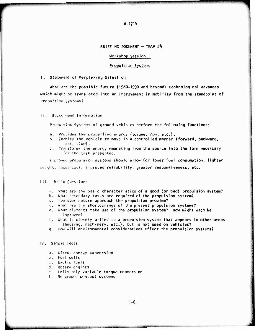
BRIEFING DOCUMENT - TEAM 0*4
Workshop Session I
Propulsion Systems
I, Statement of Perplexing Situation
What are the possible future (1980-1990 and beyond) technological advances
wnich might be translated into an Improvement In mobility from the standpoint of
Propulsion Systems?
li. BacKqround Information
Propuision Systems of ground vehicles perform the following functions:
a. Provides the propelling energy (torque, rpm, etc.)« D. Enables the vehicle to move in a controlled manner (forward, backward,
fast, slow). c. Transforms the energy emanating from the source Into the form necessary
for the task presented.
improved propulsion systems should allow for lower fuel consumption, Ilghtc
weight, lower cost, improved reliability, greater responsiveness, etc.
III. Bas ic Quest ions
•i. what are the basic characteristics of a good (or bad) propulsion system? b. What secondary tasks are required of the propulsion system? c. How does nature approach the propulsion problem? d. What are the shortcomings of the present propulsion systems? e. What elements make use of the propulsion system? How might each be
improved? f. What Is closely allied to a propulsion system that appears in other areas
(housing, machinery, etc.), but is not used on vehicles? g. How will environmental considerations effect the propulsion systems?
iV. Sample Ideas
a. üirect energy conversion b. Fuel eel Is c. Exotic fuels d. Rotary engines e. Infinitely variable torque conversion f. No ground contact systems
E-6
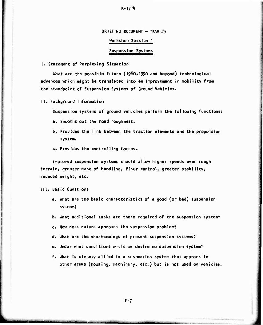
BRIEFING DOCUMENT - TEAM #5
Workshop Session 1
Suspension Systems
I. Statement of Perplexing Situation
What are the possible future (I98O-I990 and beyond) technological
advances which might be translated into an improvement in mobility from
the standpoint of Suspension Systems of Ground Vehicles.
II. Background Information
Suspension systems of ground vehicles perform the following functions:
a. Smooths out the road roughness.
b. Provides the link between the traction elements and the propulsion
system.
c. Provides the controlling forces.
Improved suspension systems should allow higher speeds over rough
terrain, greater ease of handling, finer control, greater stability,
reduced weight, etc.
III. Basic Questions
a. What are the basic characteristics of a good (or bad) suspension
system?
b. What additional tasks are there required of the suspension system?
c. How does nature approach the suspension problem?
d. What are the shortcomings of present suspension systems?
e. Under what conditions WTJH we desire no suspension system?
f. What Is cicely allied to a suspension system that appears in
other areas (housing, machinery, etc.) but is not used on vehicles.
E-7
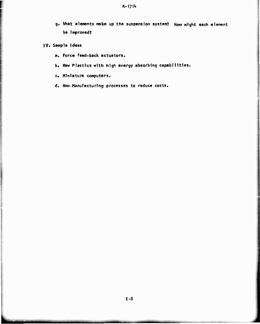
R-l?!1»
g. What elements make up the suspension system? How might each element
be Improved?
IV* Sample Ideas
a. Force feed-back actuators.
b. New Plastics with high energy absorbing capabilities,
e« Miniature computers.
d. New Manufacturing processes to reduce costs.
E-8
-- - - :,m ■■ tmmmammmmm ■ i .«. . . r
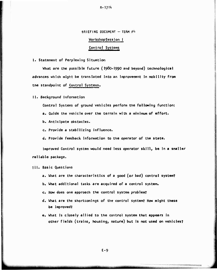
R-iyi^
BRIEFING DOCUMENT - TEAM 04
WorkshopSesslon I
Control Systems
I. Statement of Perplexing Situation
What are the possible future (I98O-I990 and beyond) technological
advances which might be translated into an improvement in mobility from
the standpoint of Control Systems.
II. Background Information
Control Systems of ground vehicles perform the following function:
a. Guide the vehicle over the terrain with a minimum of effort.
b. Anticipate obstacles.
c. Provide a stabilizing Influence.
d. Provide feedback information to the operator of the state.
Improved Control system would need less operator skill, be In a smaller
rellable package.
III. Basic Questions
a. What are the characteristics of a good (or bad) control system?
b. What additional tasks are acquired of a control system.
c. How does one approach the control system problem?
d. What are the shortcomings of the control system? How might these
be improved?
e. What is closely allied to the control system that appears in
other fields (trains, housing, nature) but is not used on vehicles?
E-9
wmtm
R-I?!^
f. What functions does the control system perform?
g. What are the attributes of the most effective system today?
IV. Sample Ideas
I. No operator required.
E-10
- — — • —
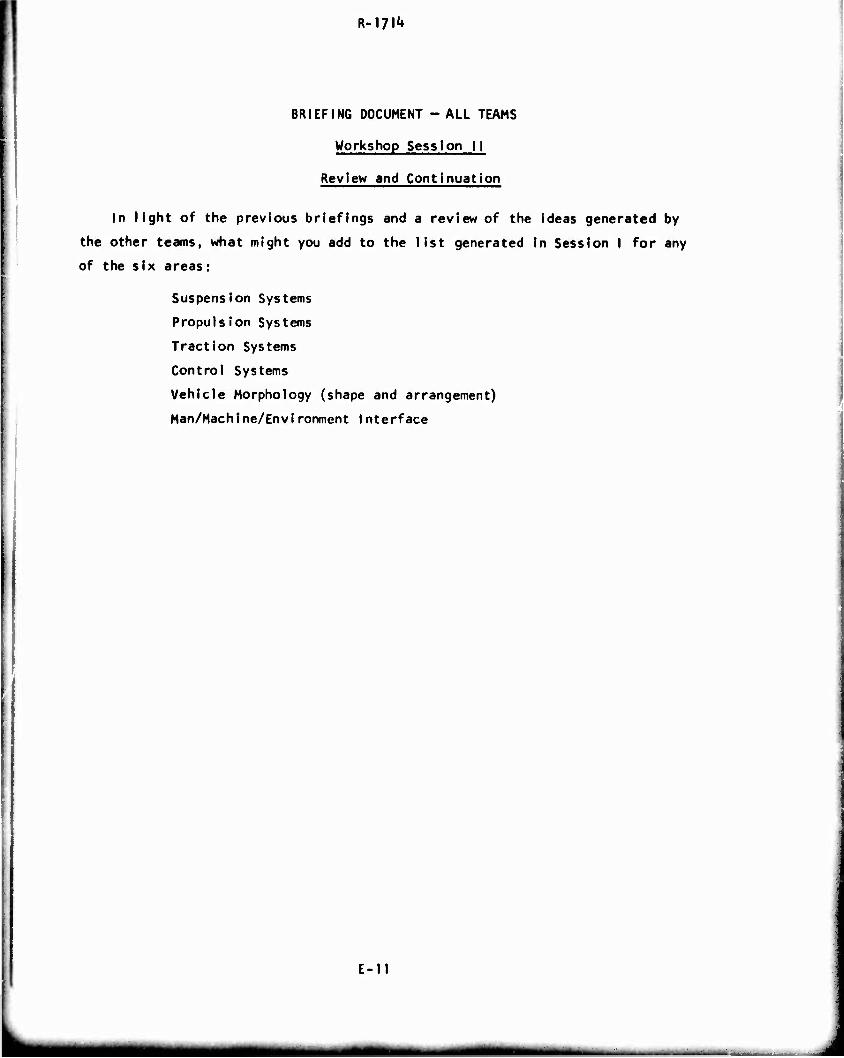
R-l?!1»
BRIEFING DOCUMENT - ALL TEAMS
Workshop Session 11
Review and Continuation
In light of the previous briefings and a review of the ideas generated by
the other teams, what might you add to the list generated in Session I for any
of the six areas:
Suspension Systems
Propulsion Systems
Traction Systems
Control Systems
Vehicle Morphology (shape and arrangement)
Man/Machine/Environment Interface
E-II
— - MM mi tm I ■ - - . - . - ..,
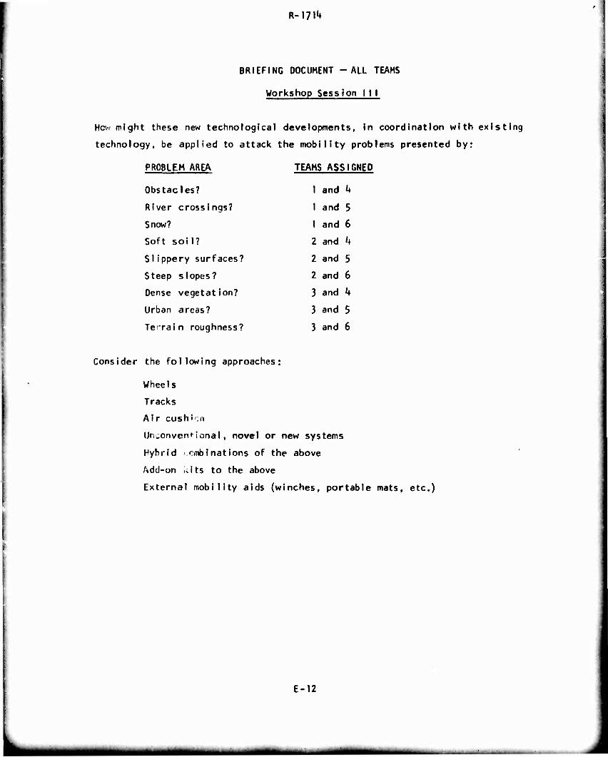
BRIEFING DOCUMENT -ALL TEAMS
Workshop Session I I I
How might these new technological developments, in coordination with existing
technology, be applied to attack the mobility problems presented by:
PROBLEM AREA
Obstacles?
River crossings?
Snow?
Soft soil?
Si ippery surfaces?
Steep slopes?
Dense vegetation?
Urban areas?
TeiTain roughness?
TEAMS ASSIGNED
I and i»
I and 5
1 and 6
2 and k
2 and 5
2 and 6
3 and k
3 and 5
3 and 6
Consider the following approaches:
Wheels
Tracks
Air cushi.n
Unconventional, novel or new systems
Hybrid ■cmbinations of the above
Add-on kits to the above
External mobility aids (winches, portable mats, etc.)
E-12
«■M
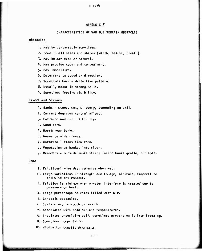
R-171^
APPENDIX F
CHARACTERISTICS OF VARIOUS TERRAIN OBSTACLES
Obstacles
1. May be by-passable sometimes.
2. Come In all sizes and shapes (width, height, breath).
3. May be man-made or natural.
k. May provide cover and concealment.
5. May immobiIize.
6. Deterrent to speed or direction.
7. Sometimes have a definitive pattern.
8. Usually occur in strong soils.
9» Sometimes impairs visibility.
Rivers and Streams
1. Banks - steep, wet, slippery, depending on soil.
2. Current degrades control afloat.
3. Entrance and exit difficulty.
h. Sand bars.
5. Marsh near banks.
6. Waves on wide rivers.
7. Water/soil transition zone.
8. Vegetation at banks, into river.
9. Meanders - outside banks steep; inside banks gentle, but soft.
Snow
1. Frictional when dry; cohesrve when wet.
2. Large variations in strength due to age, altitude, temperature and wind environment.
3. Friction is minimum when a water interface is created due to pressure or heat.
k. Large percentage of voids filled with air.
5. Conceals obstacles.
6. Surface may be rough or smooth.
7. Associated with cold ambient temperatures.
8. Insulates underlying soil, sometimes preventing it from freezing.
9. Sometimes compactable.
10. Vegetation usually defolated.
F-l
J
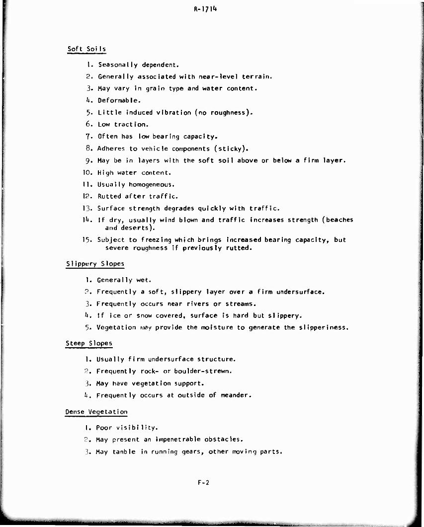
R-m^
Soft SoiIs
1. Seasonally dependent.
2. Generally associated with near-level terrain.
3. May vary in grain type and water content.
k. Deformable.
5- Little induced vibration (no roughness).
6. Low traction.
7. Often has low bearing capacity.
8. Adheres to vehicle components (sticky).
9. May be in layers with the soft soil above or below a firm layer.
10. High water content.
11. Usually homogeneous.
12. Rutted after traffic.
13. Surface strength degrades quickly with traffic.
I^. If dry, usually wind blown and traffic increases strength (beaches and deserts).
15. Subject to freezing which brings increased bearing capacity, but severe roughness if previously rutted.
Slippery Slopes
1. Generally wet.
2. Frequently a soft, slippery layer over a firm undersurface.
3. Frequently occurs near rivers or streams.
h. If ice or snow covered, surface is hard but slippery.
5. Vegetation may provide the moisture to generate the siipperiness.
Steep Slopes
1. Usually firm undersurface structure.
2. Frequently rock- or boulder-strewn.
3. May have vegetation support.
U, Frequently occurs at outside of meander.
Dense Vegetation
1. Poor visibi 1 ity.
2. May present an impenetrable obstacles.
3. May tanble in running gears, other moving parts.
F-2
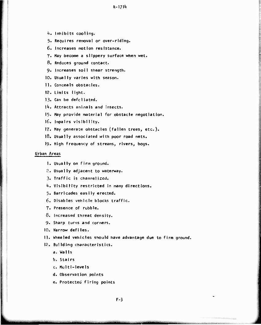
R-m4*
k. Inhibi ts coolIng.
5. Requires removal or over-riding.
6. Increases motion resistance.
7. May become a slippery surface when wet.
8. Reduces ground contact.
9. Increases soil shear strength.
10. Usually varies with season.
11. Conceals obstacles.
12. Limits light.
13. Can be defcliated.
\k. Attracts aninals and insects.
15. May provide material for obstacle negotiation.
16. Impalrs vis ibi I ity.
17« May generate obstacles (fallen trees, etc.).
|8. Usually associated with poor road nets.
19^ High frequency of streams, rivers, bogs.
Urban Areas
1. Usually on firm ground.
2. Usually adjacent to waterway.
3. Traffic is channelized.
h. Visibility restricted in many directions.
5. Barricades easily erected.
6. Disables vehicle blocks traffic.
7. Presence of rubble.
8. Increased threat density.
9. Sharp turns and corners.
10. Narrow defiles.
11. Wheeled vehicles should have advantage due to firm ground.
12. Building characteristics.
a. Walls
b. Stairs
c. Multi-levels
d. Observation points
e. Protected firing points
F-3
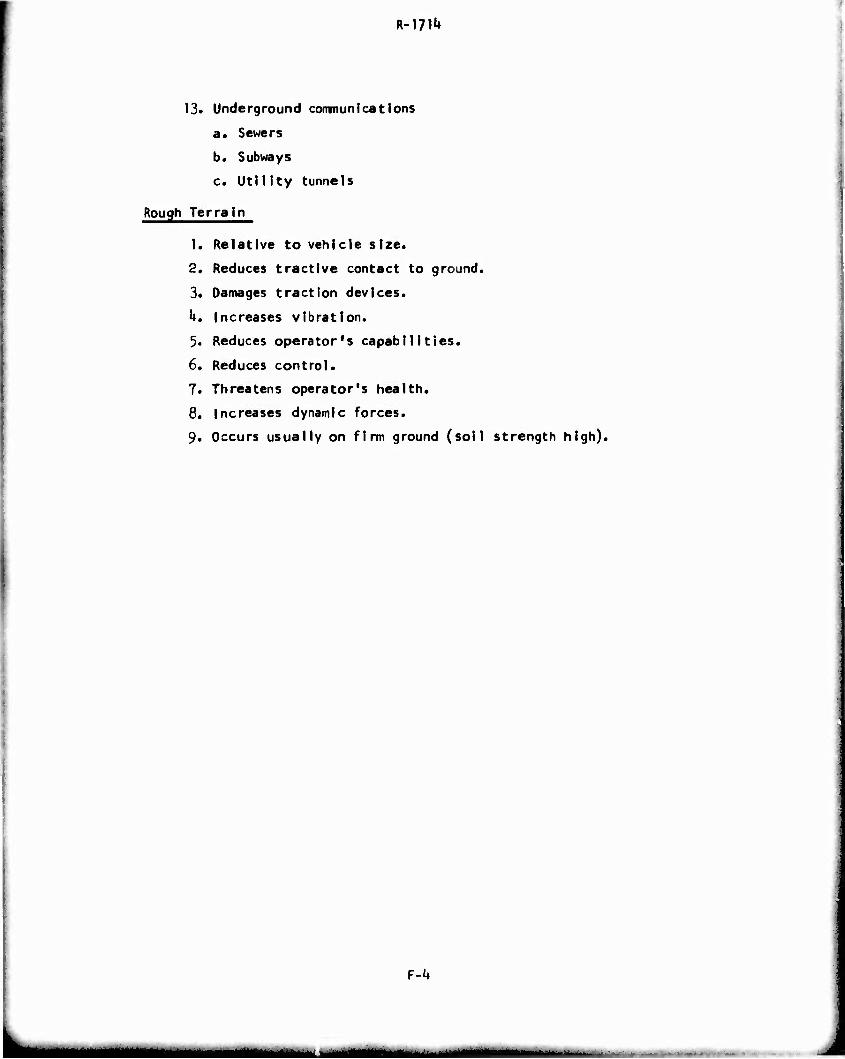
R-I7I^
13* Underground communications
a. Sewers
b. Subways
c. Utility tunnels
Rough Terrain
1. Relative to vehicle size.
2. Reduces tractive contact to ground.
3. Damages traction devices.
k. Increases vibration.
3. Reduces operator's capabilities.
6. Reduces control.
7. Threatens operator's health,
8. Increases dynamic forces.
9. Occurs usually on firm ground (soil strength high).
F-k
llMM——
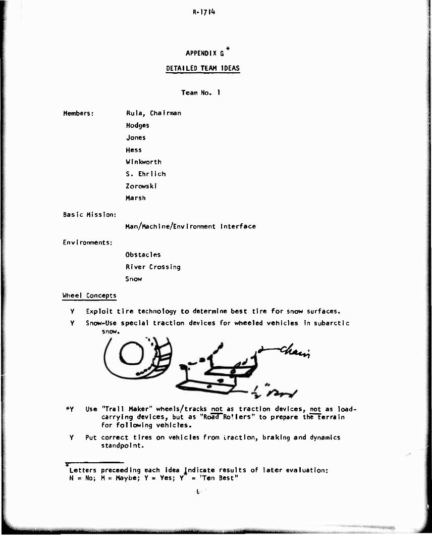
R-iyi1»
APPENDIX G*
DETAILED TEAM IDEAS
Team No. I
Members: Rula, Chairman
Hodges
Jones
Hess
Wlnkworth
S. Ehrlich
Zorows kl
Marsh
Basic Mission:
Man/Mach Ine/EnvIronment Interface
Environments:
Obstacles
River Crossing
Snow
Wheel Concepts
Y Exploit tire technology to determine best tire for snow surfaces.
Y Snow-Use special traction devices for wheeled vehicles In subarctic snow.
*—*****
*Y Use "Trail Maker" wheels/tracks not as traction devices, not as load- carrying devices, but as "Road Ro'lers" to prepare the terrain for following vehicles.
Y Put correct tires on vehicles from traction, braking and dynamics standpoint.
If Letters preceeding each idea Indicate results of later evaluation: N = No; M = Maybe; Y = Yes; Y = "Ten Best"
L
^—illfl I ^Mi—Ill i-.
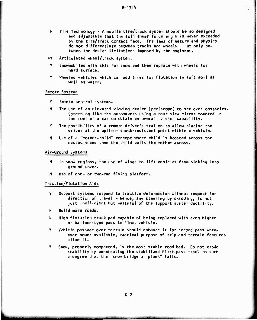
R-l?!1*
N Tire Technology - A mobile tire/track system should be so designed and adjustable that the soil shear force angle is never exceeded by the tire/track contact face. The laws of nature and physics do not differentiate between tracks and wheels ut only be- tween the design limitations imposed by the engineer.
*Y Articulated wheel/track system.
Y Snowmobiles with skis for snow and then replace with wheels for hard surface.
Y Wheeled vehicles which can add tires for flotation in soft soil as welI as water.
Remote Systems
Y Remote control systems.
M The use of an elevated viewing device (periscope) to see over obstacles. Something like the automakers using a rear view mirror mounted in the roof of a car to obtain an overall vision capability.
Y The possibility of a remote driver's station to allow placing the driver at the optimum shock-resistant point within a vehicle.
N Use of a "mother-child" concept where child is boosted across the obstacle and then the child pulls the mother across.
Air-Ground Systems
H In snow regions, the use of wings to lift vehicles from sinking into ground cover.
M Use of one- or two-man flying platform.
Traction/Flotation Aids
Y Support systems respond to tractive deformation without respect for direction of travel - hence, any steering by skidding, is not just inefficient but wasteful of the support system ductility.
N Bui Id more roads.
N High flotation track pad capable of being replaced with even higher or balloon-type pads to float vehicle.
Y Vehicle passage over terrain should enhance it for second pass when- ever power available, tactical purpose of trip and terrain features allow it.
Y Snow, properly compacted, is the most stable road bed. Do not erode stability by penetrating the stabilized first-pass track to such a degree that the "snow bridge or plank" fails.
G-2
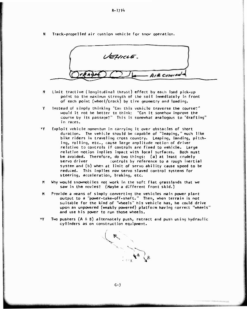
R-I/l^
Track-propelled air cushion vehicle for snow operation.
Ofefrsccg-
23gmZ32 N Limit tractive (longitudinal thrust) effect by each load pick-up
point to the maximum strength of the soil immediately in front of each point (wheel/track) by tire geometry and loading.
Y Instead of simply thinking "Can this vehicle traverse the course?" would it not be better to think: "Can It somehow improve the course by its passage?" This is somewhat analogous to "drafting" in races.
*Y Exploit vehicle momentum in carrying it over obstacles of short duration. The vehicle should be capable of "leaping," much like bike riders in traveling cross country. Leaping, landing, pitch- ing, rolling, etc., cause large amplitude motion of driver relative to controls If controls are fixed to vehicle. Large relative motion implies impact with local surfaces. Both must be avoided. Therefore, do two things: (a) at least crudely servo driver controls by reference to a rough inertial system an»! (b) when at limit of servo ability cause speed to be reduced. This implies new servo slaved control systems for steering, acceleration, braking, etc.
M Why would snowmobiles not work In the soft flat grasslands that we saw in the movies? (Maybe a different front skid.)
M Provide a means of simply converting the vehicles main power plant output to a "power-take-off-shaft." Then, when terrain is not suitable for the kind of "wheels" his vehicle has, he could drive upon an unpowered (weakly powered) platform having correct "wheels" and use his power to run those wheels.
*Y Two pushers (A & B) alternately push, retract and push using hydraulic cylinders as on construction equipment.
G-3
«M Itai MM
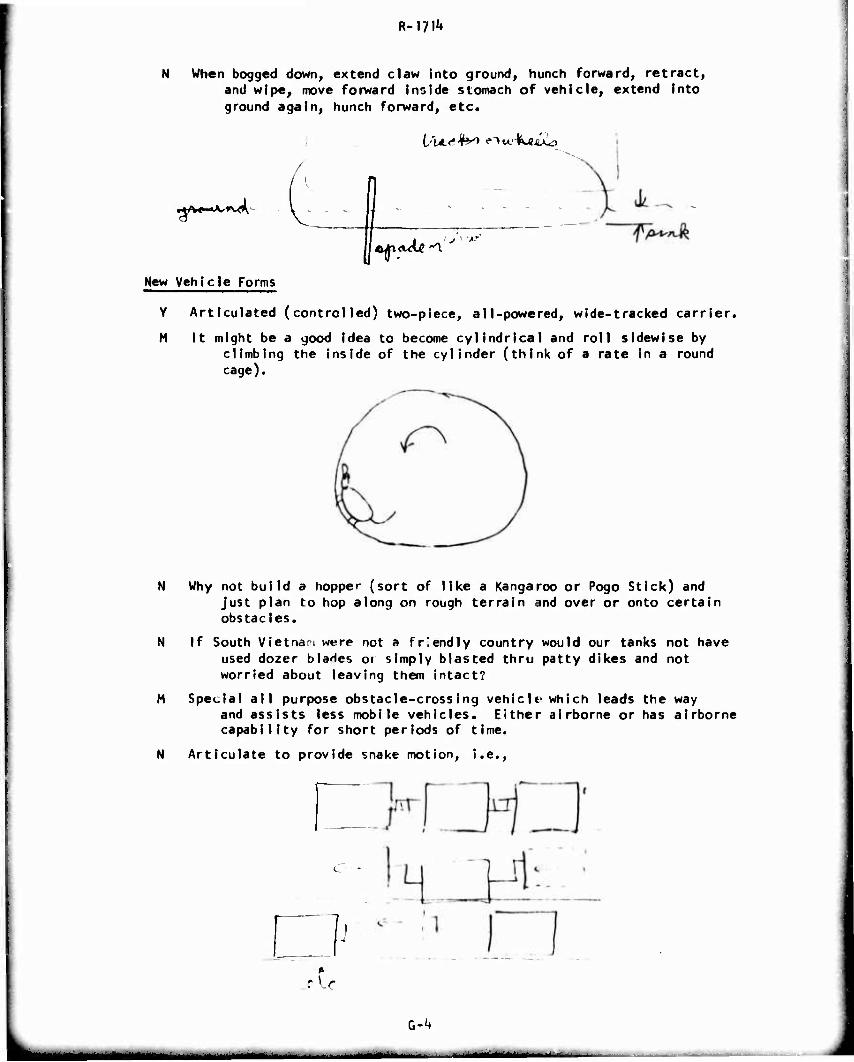
R-m't
N When bogged down, extend claw into ground, hunch forward, retract, and wipe, move forward inside stomach of vehicle, extend into ground again, hunch Forward, etc.
[AA^Jht .Mw.'Keü.\li)
i-MJV \f*«-*K-
New Vehicle Forms
f «Jjl»\ '
Y Articulated (controlled) two-piece, all-powered, wide-tracked carrier.
M It might be a good idea to become cylindrical and roll sidewise by climbing the inside of the cylinder (think of a rate in a round cage).
N Why not build a hopper (sort of like a Kangaroo or Pogo Stick) and Just plan to hop along on rough terrain and over or onto certain obstacles.
N If South Vietnan were not a friendly country would our tanks not have used dozer biaHes or simply blasted thru patty dikes and not worried about leaving them intact?
M Special all purpose obstacle-crossing vehiclf which leads the way and assists less mobile vehicles. Either airborne or has airborne capability for short periods of time.
N Articulate to provide snake motion, i.e.,
I-' .rU
G-^
■ - -
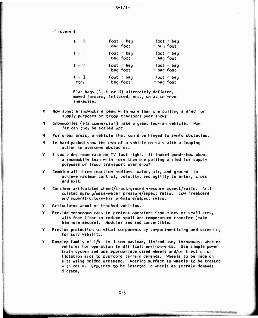
R-I?!^
movement
t --- 0
t = I
t = 2
t = 3 etc.
foot • bag bag foot
foot < bag bag foot
foot bag bag foot
foot < bag bag foot
foot < bag ' be i foot
foot <■ bag ; bag foot
foot < bag bag foot
foot < bag ' bag foot
Flat bags (U, 6 or 8) alternately deflated, moved forward, inflated, etc., so as to move snakewise.
M How about a snowmobile team with more than one pulling a sled for supply purposes or troop transport over snow?
N Snowmobiles (ala commercial) make a great two-man vehicle. How far can they be scaled up?
M For urban areas, a vehicle that could be hinged to avoid obstacles.
M In hard packed snow the use of a vehicle on skis with a leaping action to overcome obstacles.
Y I saw a dog-team race on TV last night. It looked good—how about a snowmobile team with more than one pulling a sled for supply purposes or troop transport over snow?
Y Combine all three reaction mediums—water, air, and ground—to achieve maximum control, velocity, and agility to enter, cross and exit.
N Consider articulated wheel/track-ground nressure aspect/ratio. Arti- culated sprung/mass-water pressure/aspect ratio. Low freeboard and superstructure-air pressure/aspect ratio.
Y Articulated wheel or tracked vehicles.
Y Provide monocoque cabs to protect operators from mines or small arms, with foam liner to reduce spall and temperature transfer (make him more secure). Modularized and convertible.
Y Provide protection to vital components by compartmentizing and screening for survivability.
Y Develop family of \/k- to I-ton pay load, limited use, throwaway, wheeled vehicles for operation in difficult environments. Use simple power train system and use appropriate sized wheels and/or traction or flotation aids to overcome terrain demands. Wheels to be made on site using molded urethane. Wearing surface to wheels to be treated with resin. Grousers to be inserted in wheels as terrain demands dictate.
G-5
•HMMaM
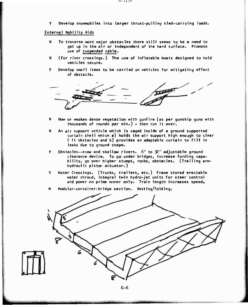
Y Develop snowmobiles into larger thrust-pulling sled-carrying loads.
External Mobility Aids
N To traverse most major obstacles there still seems to be a need to get up in the air or independent of the hard surface. Promote use of suspended cable.
N (For river crossings.) The use of inflatable boats designed to hold vehicles secure.
Y Develop small items to be carried on vehicles for mitigating effect of obstacle.
N Mow or weaken dense vegetation with gunfire (as per gunship guns with thousands of rounds per min.) - then run it over.
N An air support vehicle which is caged inside of a ground supported curtain shell which a) holds the air support high enough to clear 2 ft obstacles and b) provides an adaptable curtain to fill in leaks due to ground shape.
Y Obstacles--snow and shallow rivers. 6" to 32" adjustable ground clearance device. To go under bridges, Increase fording capa- bility, go over higher stumps, rocks, obstacles. (Trailing arm- hydraulic piston actuator.)
Y Water Crossings. (Trucks, trailers, etc.) Frame stored erectable water shroud, Integral twin hydro-jet units for steer control and power on prime mover only. Train length Increases speed»
M Modular-container-bridge section. Nesting/folding.
G-6
^«a^MMHMM^ r— ■'- -
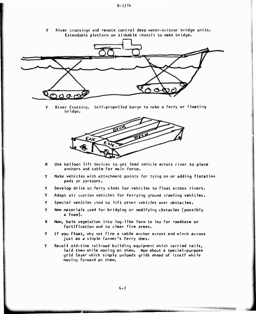
R-l?!'*
River crossings and remote control deep water-scissor bridge units. Extendable platform on sinkable chassis to make bridge.
Y River Crossing. Self-propelled barge to make a ferry or floating bridge.
M
Y
Y
Y
Y
Y
N
Y
Y
Use balloon lift devices to get lead vehicle across river to place anchors and cable for main force.
Make vehicles with attachment points for tying on or adding flotation pads or pontoons.
Develop drive on ferry sleds for vehicles to float across rivers.
Adapt air cushion vehicles for ferrying ground crawling vehicles.
Special vehicles used to lift other vehicles over obstacles.
New materials used for bridging or modifying obstacles (possibly a foam).
Mow, bale vegetation into log-like form to lay for roadbase or fortification and to clear fire areas.
If you float, why not fire a cable anchor across and winch across just as a simple farmer's ferry does.
Recall old-time railroad building equipment which carried rails, laid them while moving on them. How about a special-purpose grid layer which simply unloads grids ahead of itself while moving forward on them.
G-7
•' -.*i ■i'«imiii.^>i<miMi»»i>
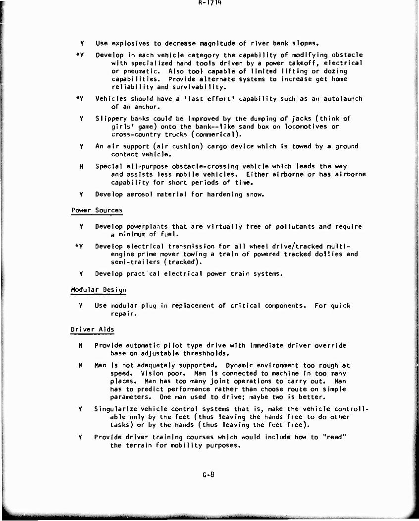
R-]7\'*
Y Use explosives to decrease magnitude of river bank slopes.
*y Develop in each vehicle category the capability of modifying obstacle with specialized hand tools driven by a power takeoff, electrical or pneumatic. Also tool capable of limited lifting or dozing capabilities. Provide alternate systems to increase get home reliabiIity and survivabi1ity.
*Y Vehicles should have a 'last effort' capability such as an autolaunch of an anchor.
Y Slippery banks could be improved by the dumping of jacks (think of girls' game) onto the bank—like sand box on locomotives or cross-country trucks ( commerical).
Y An air support (air cushion) cargo device which is towed by a ground contact vehicle.
M special all-purpose obstacle-crossing vehicle which leads the way and assists less mobile vehicles. Either airborne or has airborne capability for short periods of time.
Y Develop aerosol material for hardening snow.
Power Sources
Y Develop powerplants that are virtually free of pollutants and require a minimum of fuel.
*Y Develop electrical transmission for all wheel drive/tracked multi- engine prime mover towing a train of powered tracked dollies and semi-trailers (tracked).
Y Develop pract cal electrical power train systems.
Modular Design
Y Use modular plug in replacement of critical components. For quick repai r.
Driver Aids
N Provide automatic pilot type drive with immediate driver override base on adjustable threshholds.
M Man is not adequately supported. Dynamic environment too rough at speed. Vision poor. Man is connected to machine in too many places. Man has too many joint operations to carry out. Man has to predict performance rather than choose route on simple parameters. One man used to drive; maybe two Is better.
Y Slngularize vehicle control systems that is, make the vehicle controll- able only by the feet (thus leaving the hands free to do other tasks) or by the hands (thus leaving the feet free).
Y Provide driver training courses which would include how to "read" the terrain for mobility purposes.
G-8
R-iyi^
Y Air-conditioning for hot climates; heating for cold climates.
Y Have the seat of the vehicle adjustable to make driver more effi- cient and more comfortable«
N Computer system to help driver use the right techniques for his specific problem.
Y Driver ejection device for operations in water.
*Y Develop driver simulator training devices.
Y Reduce displays through automation (automatic switching gear).
Y Provide alternate systems to increase get-home reliability and survivabi11ty.
N Provide a comfortable vehicle environment, i.e., noise, temperature, vibration.
Y A sensing device for all parts of vehicle to see problems arising.
Y Isolate occupants from noise, shock, vibration, and fumes (location).
Y Provide life support console to reduce his obligations and non- operator functions.
Y Route selection, radially, from present vehicle position should extend, tactically, for a few hundred yards. Route selection should provide information on probability of negotiation and estimated speed possible. Vision from vehicle may not be adequate to see over hills through brush around corners or, in dust, very far. Provide intervehicle communication between scout vehicles and main vehicle to other vehicles; this should consist of a plan-position-indicator, speed made good, and vehicle code. The driver would have ability to "learn from" his colleagues at extended (up to 500 yard) range. Develop simplified vehicle controls.
Y Panoramic terrain display.
N Isolate crew from vehicle and environment; provide separate life control system, but permit complete body freedom. Operator Is connected to machine in too many places.
Y Develop devices to moderate terrain impact.
*Y Stabilize "sprung" mass only.
Y Improve suspension system for absorbing energy inputs—use variable spring rates.
Y Increase wheel or track travel.
Y Provide commonality between vehicles in operator station and other crew areas.
Y Advance Terrain-Sensor System for controlling vehicle.
N Provide integrated automatic controls.
G-9
m—m
R-\7\i*
Y Simplified control systems.
Y Provide alternate vehicle control points, depending on mission or situation. Singularize vehicle control systems, that Is, make the vehicle controllable only by the feet (thus leaving the hands free to do other tasks) or by the hands (thus leaving the feet free).
Y Improve train/trail maneuverability.
Y Divide vehicle function display observations among operating personnel such as Is currently done In aircraft.
Y Flberoptics information transmission.
M Use of remote visibility sensors; remote from vehicle (possibly air- planes) controlled by operator of vehicle.
Y A simple may (or better, local cheap and dirty air photo) board with approximate local position indicator which will Inform driver of best driving tactics; I.e., speed up to jump, steer to the right around a terrain feature, etc. A navigator In simplest form can move the indicator and give verbal advice (and replace maps). Command planning would be possible (experience of yours and others from past trips can be noted, etc.)
Y Feedback of vehicle response to modify or change response characteris- tics; modify vehicle response based on response feedback.
Y Provide inost level ride platform possible in the geomotry available.
»Y The need to develop more shock-resistant men. Possibly encase them in a fluid—like they do cameras for taking movies from helicopters, or the compass encased in oil or like a person's eyeballs. Possibly a "G" suit, like aircraft pilots to react to rapid changes in vibration. Suspend driver in a harness so that his body is pro- tected against nitting the seat and causing stress on spine.
M Air cushion the vehicle with wheels for control of turning, braking, and speed. One basic problem has been that the operator drives by the seat of his pants or is a victim of the terrain. He therefore needs higher rate suspension systems commensurate with his required operation.
*Y Enhance driver vision, day or night.
Non-Hardware Ideas
Y Avoid or maintain constant contact aspect/ratio regardleis of attitude.
Y River Crossing: For it, don't float it.
Y Develop systems for sensing, interpreting, and varying vehicle char- acteristic automatically such that obstacle performance (speed of crossing) is Increased.
N The laws of nature and physics do not differentiate between tracks and wheels. But only between the design limitations imposed by the engineer. Develop software to evaluate the terrain for mobility purposes in the theater of operations.
G-IO
»MliaMMiHfcMlÜ
R-m**
Y Develop techniques for locating potential river crossing sites.
Y Assemble current obstacle technology In usable form.
*Y Develop a computer compatible terrain factor measuring and recording system for field use.
Y Conduct terrain studies to establish magnitude of obstacle problem through knowledge of frequency of occurrence and area I occupancy Information.
G-ll
tät~- ■ i »mi i—i«
R-I?!^
Team No. 2
Members: Carr, Chairman
Markow
Boudlnot
Bekker
Fad urn
Banks
Zlem
Bradshaw
Basic Mission:
Envi ronments:
Wheel Concepts
Vehicle Morphology
Soft Soil
SIippery Surfaces
Steep Slopes
*Y A 'condual" (multiple concentric pneumatic chambers), radian and other tire/wheel designs.
*Y Reduced vulnerability tires by multiple structure, castable polyure- thane, ball filled, non-pneumatic, etc.
M Expanding multiple wheel disks to use as viscous shear disks for fluid mud propulsion.
**Y Wheel-track convertible logistical vehicles (based on new power train/steering technology).
M Air cushion with wheels for control of turning, braking and speed.
M Wheel-pump device where the tires rotate 90 , to get better thrust.
N Provide warning system which would be activated when tire or track slip exceeds the safe maximum, predetermined for each soil type.
N Provide automatic tire inflation and torque control which would adjust the tire and thrust pressure to soil conditions for optimum traction.
G-12
MM^fcMta^i ■ ■ 1 ». ■- - -- .—
R-I?^
**Y Multiple soft roller vehicle with air film or magnetic suspension between rollers and body and propelled by a gas generator or linear electrical motor driving magnetic tape or metallic wire reinforced bags.
Remote Systems
M Use balloons as complement to combat vehicle—as observation platform.
N A remote driver's station to allow placing the driver at the optimum shock resistant point within a vehicle.
N Orone-carrying TV to aid In route selection.
**Y Remote control by simu I at I on-telemetry to operator.
*Y Mother-daughter concept: remote controlled vehicles to provide observation, mine detection, electronic countermeasures; like aircraft for a Navy task force; or drones to a manned bomber force.
Air/Ground Systems
N Use flying platforms.
N RAM Air wing—transient contact vehicle-part wheel, part aero support.
**Y Combat vehicles which can be transported by U.S. Heavy Lift Heli- copters (18 tons).
Traction/Floatation Aids
*Y GEM assisted heavy armored vehicles to reduce one-pass 20-30 VCI trafficebllity capability to 7-10 VCI.
M Use high frequency vibratory skid to reduce surface friction— propel !er/fan/Jet for thrust. Utilize existing vibration of propulsion system, use this energy and to apply to skid.
*Y Suction cups or polyurethane tires and track pads impregnated with metallic grit or optimised agressive grousers and treads for high traction on slippery surfaces.
M Equip trailers with drive system that can feed off of rear differ- ential and provide assist when necessary.
M Use powered trailers like the British dc.
**Y Flexible tracks which would provide longer life and weight saving through the distribution of peak loads.
**Y Track suspension supported by ski-type, sliding, low friction sur- faces (Instead of road wheels) - air, fluid, solid lubricant, magnetic.
N Cycloidal locomotion (like helicopter with low disk loading); exploit dynamic strength of soil.
G-13
mm
R-l?!^
N Provide ski-type track suspension, in addition to the regular road wheels, which could be lowered to support the vehicle In case of extremely soft ground with purpose of reducing the peak loads incurred in track road wheel systems.
N Use gas turbine exhaust for the partial lifting of the vehicle, in critical soil conditions by providing simple collapsible air cush ions.
M Fold down inflatable air cushion lifting device kit to reduce ground pressure.
N Hot ski in saturated soils (use engine exhaust) flashes water to provide a steam interface or dries out soil for better trafflc- abiIIty«
N Glue emitting traction aid--for slippery surface (houst-f1y).
M Use unidirectional thrust «irface on vibrating skid—(like vibrating conveyor belts).
Y Deep penetration, aggressive treads for tires and tracks.
Y Variable geometry tracks: low pressure for soft soils, high pres- sure for slippery surfaces.
New Vehicle Forms
N Development of wheel - screw vehicle.
N Development of the track screw combination.
**Y Develop an advanced air-roll vehicle.
N Tri-track system.
**Y Air cushion with fore and aft thin knife-like wheel disks to provide lateral restraint - travel on slopes would now be possible.
N Flexible accordian, snake-like propulsion vehicle.
M Long, very minimum profile, articulated vehicle—bridging on demand (pitch control)--with centerline wheel/track suspension; stabi- lized by momentum, wheels, gyros or pulse jets.
**Y Articulated tracked vehicles.
M Make a very long articulated vehicle form by entrainment.
Y Run tracks In opposite directions to generate trench for vehicle protect Ion.
N Stabilization system for center-supported vehicles.
N Go fast - use high energy thruster, planing hull geometry, high slip wheel propulsion for high speed thrust.
N Build vehicle in shape of two concentric spheres—inner one stabi- lized, outer one rotating for locomotion.
M Use honeycomb structure and carry fuel within voids of honeycomb.
M Articulated armored vehicles with an armored joint integrated with vehicle body instead of being attached to it.
0-14
R-l?«1»
M Dynamically coupled vehicle train—rigid for Impulsive loads; arti- culated for normal motions—pneumatic or hydraulic coupling device.
M High speed, very weak soil vehicles—exploit Inertial soil effects of saturated soils. Use external thrust (not wheels); plane on soil much as a planing boat.
M Pillow drive.
M GEM sleds pulled by tracked or air-roll vehicle.
**Y Provide protection cily for vital components by compartmentalizing.
*y Pathfinder vehicle with very high pressure water jets for knocking down steep banks in order for it and following vehicle to exit from a ri ver.
M Totally inflatable vehicle structure—provides vehicle accommodation of surface geometry--smal1 stowed non-operating volume.
M Self-entrenching articulated vehicle—opposed, driven tracks dig a hole for low profile during stationary combat.
N Articulated air cushion vehicle.
N Use worm-likemotion.
Y Light, spaced armor for travel; fill spaces with soil for combat protection.
External Aids
N Use four small high thrust rockets burning same fuel as main pro- pulsion system to reduce ground pressure - Could also serve as a dash propulsion.
N Hang vehicle from a kite in the Jet stream.
N Use anti-gravity device.
N Establish soil anchor on hill top - all operational vehicles climb the cable.
N Carry "tire chain" liquid to be sprayed over slippery surface when needed.
N Fill trail with path of water and float on It.
N Provide In front of the vehicle some sort of spreaders and/or sprayers, which would cover the slope with anti-slip substances.
N Use balloons as lifters—Inflated from hot exhaust gases—when stuck in mud.
Y Provide bulldozer blade or backhoe to facilitate getting up banks.
N Fire grabbling hooks attached to a winch or capstan to aid obstacle negotiation.
*Y High-impulse JATO thrusters - primarily for water exiting.
N Surface hardener fluid.
G-15
m
R-]?!^
Power Sources
M Electronically stimulated (commanded) animals—animal robots.
N Use dog sleds.
M Use centrifugal force produced by controlled phases set of rotating eccentric masses to provide boost in lift and thrust for obstacle clearance.
M Vehicle that lives off the land; makes its own fuel.
M Compound engines.
M Turbine tracks—gases—instead of a gear box to directly drive the track.
M Stream jet propulsion—use indigenous water to provide quick scoot acceleration.
N Use explosive charges behind a big iron plate to get propulsive forces.
*Y Air over water impulse thruster to aid water exiting.
*Y Simple auxiliary propeller swimming propulsion system as used on the German WWII Jeep.
M Water dump into fan propulsion to get short acceleration capability.
Y Lightweight, wisker construction, high speed, high momentum flywheel for short bursts of high power to help in negotiating obstacles, exiting from rivers, or getting over hump power requirements for amphibians.
M Pulse jet water device—simple, lightweight, no drive train-water propulsion system.
**Y Alternate fuels and power plants to replace hydrocarbon fuels.
N Nuclear ground propulsion.
N Non air-breathing propulsion system for burrowing or submerged vehicle.
M Make non-flammable fuels.
N Electromagnetic propulsion and suspension.
**Y Microwave power transmission to vehicles from primary power source be investigated.
Modular Concepts
**Y Component modular structured vehicles.
**Y Advanced state-of-the-art electric powered hub. Exploit the evolving super magnetic materials and micrologic electronics.
G-16
R-iyi**
Driver Aids
M Active suspension systems.
M Provide a warning system which would be activated in case of approach- ing Imminent overturning of the vehicle.
Y Automatic control of speed and movement for individual vehicles in a convoy which can be remotely controlled or preprogrammed.
N Elevated TV for Improved view.
Y Large stroke, active or adaptive suspension system.
N Provide the driver or navigator with terrain sensing devices to read the terrain at an appropriate distance in front of the vehicle.
*Y Develop driver simulator training devices.
Y Provide driver training courses which would include how to "read" the terrain for mobility purposes.
*Y Provide precision navigation readouts for position location.
Y Liquid cushion suspension: metal particles suspended In solution and rigidity controlled by magnetic field.
N Automatically adjustable damping rate, controlled by ride severity measurement (automatic tuning away from resonance range).
N Air over hydraulic suspension system whose characteristic is con- trolled by the dynamic wheel (road wheel) load variation.
Non-Hardware ideas
M Transpiration cooling to reduce infrared signature.
*Y Use of CCR-TEN steel and/or surface coatings to reduce radar profile.
G-17
mama
R-l?!'*
Team No. 3
Members:
Basic Mission:
Envi ronments;
Dugoff, Chairman
Clark
Taylor
Schuring
Calder
R. Ehrlich
Traction Systems
Dense Vegetation
Urban Areas
Terrain Roughness
Wheel Concepts
M A quick response latable loop (tire) which will increase bearing surface as a sensor indicates need. (A pneumatic wheel with remotely controllable shape).
M A tire (pneumatic or other) with strong enough structure to replace the track.
•Y Make wheels so additional wheels can be easily attached (bolted) together to form duals, triples, etc.
Y Spherical wheels (like furniture casters) for omni-directional operation.
Y Cheap, expendable, light, track-over-wheel device, used and discarded as necessary (possibly of mylar) or nylon tape)
M Paddle wheel for propulsi^ in both land and water.
N Spiked wheels (no inflated rubber).
M Extremely large tires (or wheels) - 10 ft or larger - to change the wheel/terrain scale.
N Profiled tires which present a small surface for highways, but a large one for soft soils.
Y Control to put spikes out on wheels or tracks for Ice operations.
M Big-bag vehicle for crossing obstacles or rough ground.
G-18
tf^HMM
R-I/l^
M Attachable, lightweight cage to bolt onto wheel.
Y Wheels which change shape as they turn to present a large contact area to ground.
M Central inflation systems.
N Extremely low pressure tires.
Remote Systems
N Remote control (satellite)? for air cushion vehicles.
Y Remote controlled recon mini-vehicle.
Y Inexpensive, remote-controlled combat vehicle.
Air/Ground System
N Aerial terrain routing, use aircraft to detect or sense best route (similar to oil exploration techniques).
Y Use the mass (weight) of the soil beneath vehicle to aid traction.
Y Grouser to reach down to firm ground and then come up straight.
N Liquid track.
*Y More direct engagement of energy source to terrain (less dependence upon friction forces in soil - traction device Interface (Operation Red Sod).
M For soft ground passage, a qu«.sl-flotation system through a tire or other device with adjustable orifices to approach an air cushion device (air bearing).
Y Use reaction forces to assist traction by throwing back soil, mud, etc.
N ElectrostatI'_ repulsion system to reduce ground pressure.
M A traction system which generates an extremely large interface whose size can be controlled by terrain or soil sensors, according to need.
Y A traction force, generated and executed outside the vehicle-ground interface so as to divorce the traction generating mechanism from the vehicle supporting function,
M Use combustion gases directly to remove soft soil or obstacles In front of vehicle (Red Sod).
M A responsive track system with grousers that vary according to the so. I surface, working at front or rear (or both), which will present a greater area normal to the appropriate direction, as it is needed.
M Track w/lugs engaged in inverse proportion to speed - work in combi- nation w/wheels. High-speed hard surface - all wheels. Low speed soft surface - all track. Continuous, variation between the both kinds.
G-19
^mmtm
R-I?!^
N Variable aspect track-width which varies with speed (by centrifugal act ion)?
M Adjustable track axles.
*Y Technique for obtaining thrust force from obstacles (rocks, trees).
M Fluid filled bag suspension, bottom surface covered with ball bearings.
M Floor Scrubber analogy: fluid bed laid down and picked up behind vehicle.
Y Better (lighter) skirt materials for ACV.
Y Development of materials which adhere to "slippery" surfaces.
N Larger traction components would make terrain "look" smoother.
New Vehicle Forms
Y Inching vehicle - articulated vehicle which selectively moves one part at a time forward by selective expanding and contracting the connecting joints.
N Inchworm traction.
M Traction-like worms (accordion like traction): cylinder which can expand and contract.
M Design vehicle so that another vehicle could surmount it easily for: (1) mobile ramp, (2) easily bypassed when disabled In defiles.
M CombuStion-gas-cushion vehicle.
M Gyro vertical balance to allow vertically unstable configuration to remain upright In order to form motorcycle trains.
N Armored Cherry Picker for getting at uppe-- floors of buildings.
M Armored one-man vehicle.
Y Motorcycles, motor scooters, trail bikes.
M Climbing vehicle with force-feedback arms (climbs up outsides of buiIdings).
N Stair - climbing vehicle.
Y Motorcycle train with stabilizing mechanism such as outriggers for stationary mode.
M Bellyless veh'cle.
M Low-cost, thrrw-away, lightly-armored, recoi less-armed combat vehicle, which can be adapted from present commercial production to flood the battlefield In time of war.
Y Re-think articulated vehicle concept for tanks and ARCS.
M SkiIng-walking machine (use skiing motion for propulsion).
Y Monkey machine (swing from tree to tree).
G-20
MM! I -
i/m
Y Vehicle which obtains propulsive forces by grabbing vegetation.
Y Multi-unit articulated body (matrix of hinges?)
Y Vehicle which can enter and exit thru manhole and operate in sewers for urban warfare.
Y Jumping vehicle (a la soil compactor) as a pogo-stick-type vehicle.
Y Multiple forms of traction devices on same vehicle (e.g., ACV with rubber tires).
M Build vehicle in shape of circle or elipse with gyro stabilizer.
Y Lengthen vehicle (by entraining) to smooth ride.
Y Air cushion vehicle technology which will allow accurate steering.
N Underground burrowing (as a ground hog).
N Liquid cushion (vs. air cushion).
N Push thru the earth and move it on (as an Archimedes screw).
External Mobility Aids
Y Rocket for obstacle hopping.
Flood ruts, then float in them. N
*Y
Y
N
N
Y
N
M
N
N
N
A highly mobile pioneer vehicle equipped with many auxiliary mobility aids (winches, dozer blade, front-end loader, etc.) to clear way for following vehicles and assist their travel.
Capstan auxiliary drive for tracked vehicles (but this time do it right: make the capstan diameter larger than the drive sprockets).
Improved soil anchors for self-winching.
Satellite control to lift, etc. (like a puppet on a string).
Development of Compact High-Thrust rockets.
Development of some fluid which could be sprayed on soft or slippery ground, to make it harder or more frictional.
Front-end loader mounted on vehicle to: remove rubber, knock down walls, lift objects to upper floors.
Man-amplifier buiIding-knocker-downer.
Mobile ramp (vehicle which is also a ramp).
Jet exhaust reaction for propulsion.
Freeze dry terrain by flash of vacuum.
A lift device (balloon) which can be quickly inflated to reduce surface pressure as needed.
A Moving lake to float on—possible in marshes.
G-2i
.k< AdaB^AfiiMi
K-1/ IH
N Flood a path, then use floating vehicles.
Y Self-launching grapling hook or soil anchors.
N Ground leveler (bulldozer blade) in front of vehicle.
M Equip vehicle with chain saw in front to clear out vegetation.
M Laser obstacle disintegrator.
N Capstan on vehicle to help propel across river by cable assist.
M Cable-assisted operations.
Y Active missile-defeating device for less weighty armour (Re-do dash-dot system in light of new computer and sensor technology).
Y Big bag - place vehicle or people in large bag.
M Tree-farmer equipped vehicle to clear out forest, lay ramps with felled trees, etc.
M Movable shield to armor part needed, thus reduce total required armor.
H Cable-carrying balloon towed by small ground vehicle through dense vegetation.
M Separate water from soil by vacuum, polarization, heat application, pressure.
Y Rapidly hardening foam to spread out vehicle bearing pressure.
M Fast growing vegetation whose root structure strengthens soil and is not degraded by traffic.
N A lift for disabled vehicles so others can go under or around.
Y One-man rocket (or turbine or air screw) assisted propulsion system (non-flying) to aid in the propulsion of a person or skis, roller skates, bicycle, air bearing.
M Bow up bags w/exhaust for flotation.
Y Armor shell (self-supporting) to be pushed along by a vehicle inside.
Power Sources
M Use fuel combustion process directly to move soil and obtain thrust.
M Use energy from fuel directly without going thru an engine to achieve thrust and control in an ACV.
*Y Use soil as the piston and fuel as propulsor, cylinder in soil.
Y Flywheel to store energy In an Idling vehicle for high acceleration starts.
M Multiple natural power sources (sun, wind, rain, etc.) to run electric motor, charge battery, etc.)
M Self-winding or pendulum drive for flywhee' wer in rough terrain.
M Material thrust motor using slurry, mud or snow.
G-22
— —'--
R-m1»
Driver Aids
Y Means of Identifying the stronger parts of the soil to obtain best footing avallable.
Y Computer-assisted dynamic suspension system to sense terrain rough- ness and adjust suspension accordingly.
M Use sonic techniques (velocity) to determine soil characteristics.
Y Use nuclear radiation to determine soil characteristics.
Y Automatic controls to optimize slip, prevent splnout.
Y Feasible control systems for walking vehicle (as per nature).
Y Electronic sensors to identify firm or smooth terrain.
Non-Hardware Ideas
*Y
Set-up a small team to review past concepts (such as presented by Nuttall) to determine reasons for discard and determine If they are worth pursuing again.
Development of traction mechanics capable of using soil strength criterion to design vehicles more accurately.
G-23
im^mmamm
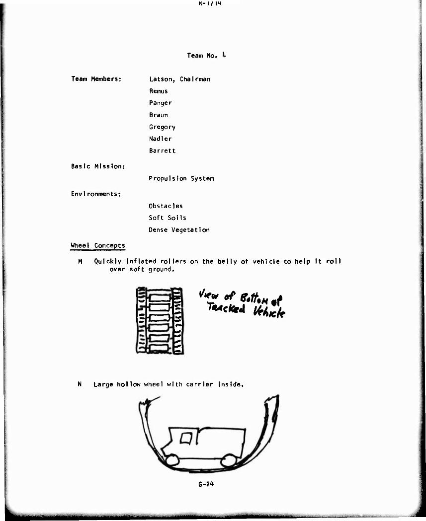
K-i/m
Team Members:
Team No. k
Latson, Chairman
Remus
Panger
Braun
Gregory
Nad]er
Barrett
Propulsion System
Obstacles
Soft Soils
Dense Vegetation
Wheel Concepts
M Quickly Inflated rollers on the belly of vehicle to help It roll over soft ground.
Basic Mission:
Environments:
a "*•' ^ «.fie,« «>
N Large hollow wheel with carrier Inside.
G-2k
mtmm^mm— - -
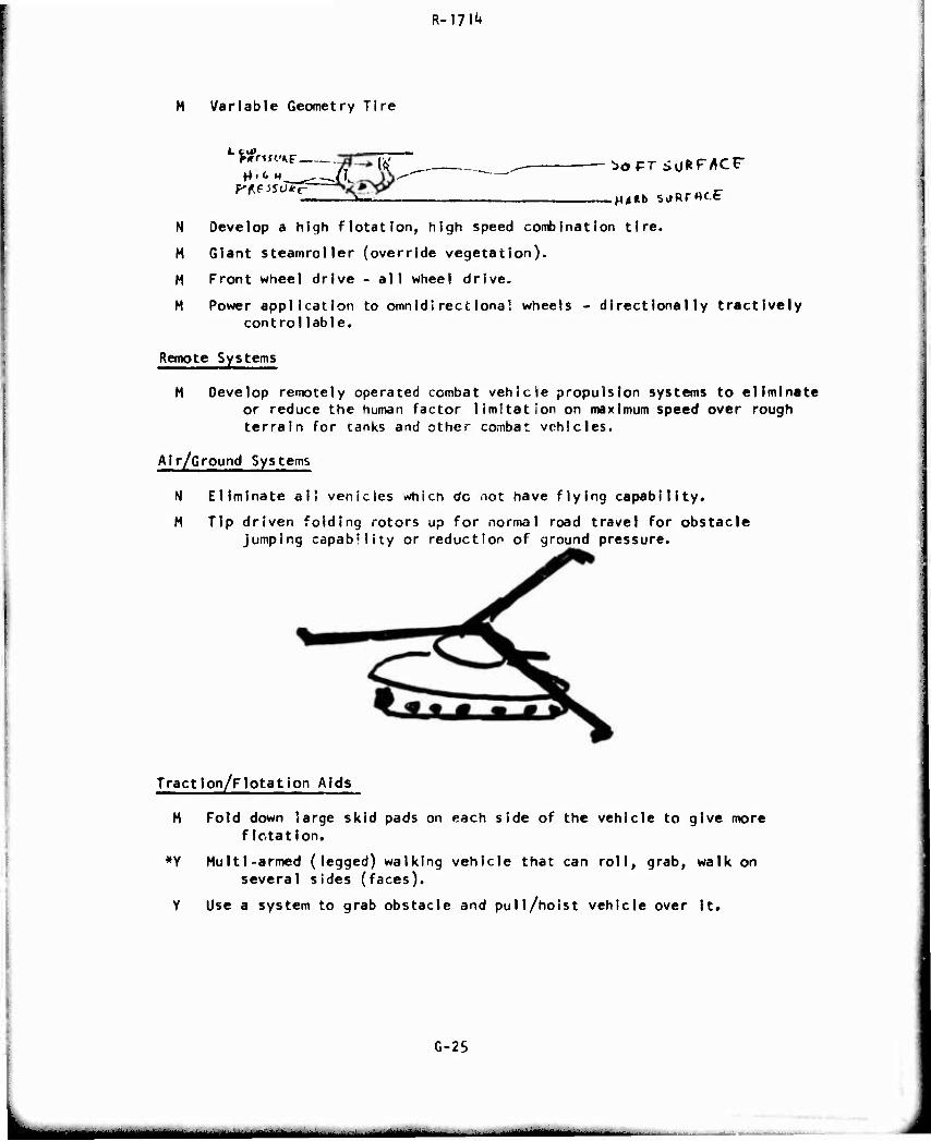
R-l?!^
M Variable Geometry Tire
Ltf. trMUKt (V
p^f iSU*t-~
N Develop a high flotation, high speed combination tire.
M Giant steamroller (override vegetation).
M Front wheel drive - all wheel drive.
M Power application to omnidirectionai wheels - dlrectlonally tractlvely controllable.
Remote Systems
M Develop remotely operated combat vehicle propulsion systems to eliminate or reduce the human factor limitation on maximum speed over rough terrain for tanks and other combat vehicles.
Air/Ground Systems
N Eliminate al! venicles wnicn do not have flying capability.
M Tip driven folding rotors up for normal road travel for obstacle jumping capability or reduction of ground pressure.
Traction/Flotation Aids
M Fold down large skid pads on each side of the vehicle to give more flotation.
*Y Multl-armed (legged) walking vehicle that can roll, grab, walk on several sides (faces).
Y Use a system to grab obstacle and pull/hoist vehicle over It.
G-25
MM -
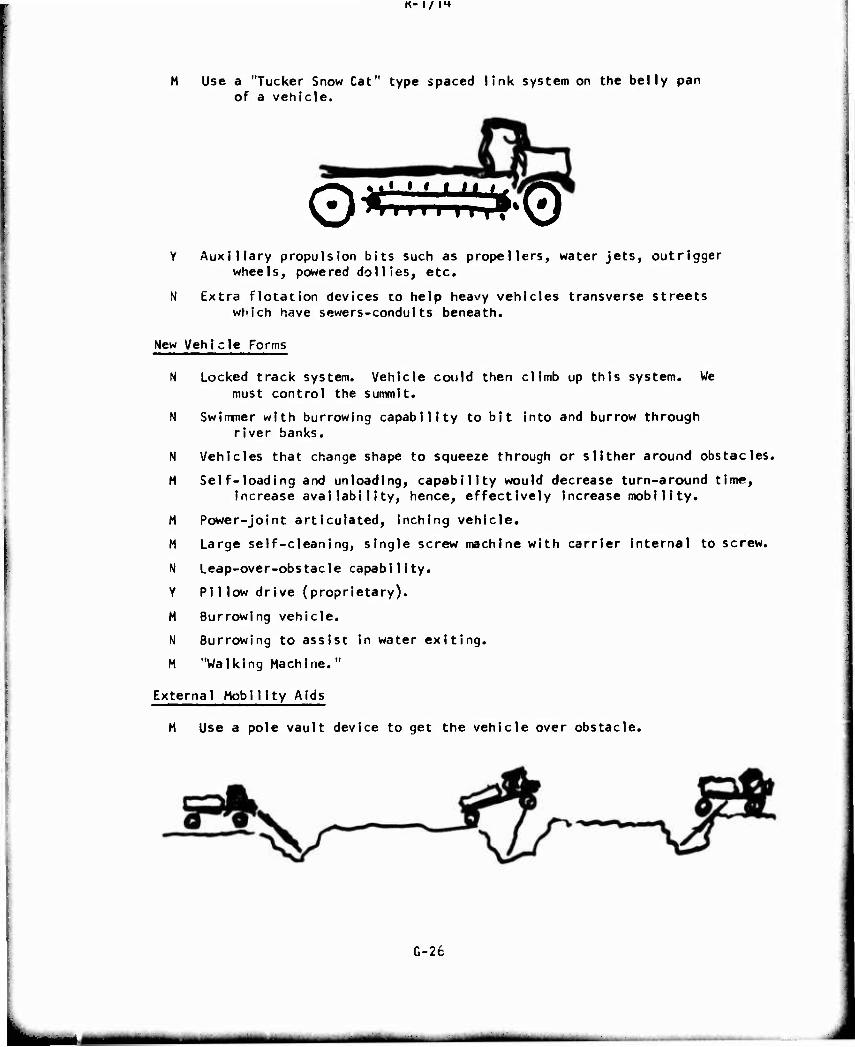
K- 1/ IH
Use a "Tucker Snow Cat" type spaced link system on the belly pan of a vehicle.
Q^s^^g Y Auxiliary propulsion bits such as propellers, water jets, outrigger
wheels, powered dollies, etc.
N Extra flotation devices to help heavy vehicles transverse streets which have sewers-conduits beneath.
New Vehi cle Forms
N Locked track system. Vehicle could then climb up this system. We must control the summit.
N Swimmer with burrowing capability to bit Into and burrow through river banks.
N Vehicles that change shape to squeeze through or slither around obstacles.
M Self-loading and unloading, capability would decrease turn-around time, increase availability, hence, effectively Increase mobility.
M Power-joint articulated, inching vehicle.
M Large self-cleaning, single screw machine with carrier internal to screw.
N Leap-over-obstacle capability.
Y Pillow drive (proprietary).
M Burrowing vehicle.
N Burrowing to assist in water exiting.
M "Walking Machine."
External Mobility Aids
M Use a pole vault device to get the vehicle over obstacle.
G-26
mtmmmtl^mtm u^aaMMM
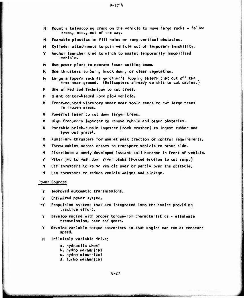
R-17I'*
M Mount a telescoping crane on the vehicle to move large rocks - fallen trees, etc., out of the way.
H Foamable plastics to fill holes or ramp vertical obstacles.
M Cylinder attachments to push vehicle out of temporary Immobiltty.
Y Anchor launcher tied to winch to assist temporarily Immobilized vehicle.
M Use power plant to operate laser cutting beam.
M Use thrusters to burn, knock down, or clear vegetation.
M Large snippers such as gardener's lopping shears that cut off the tree near ground. (Helicopters already do this to cut cables.)
M Use of Red Sod Technique to cut trees.
M Giant center-bladed Rome plow vehicle.
M Front-mounted vibratory shear near sonic range to cut large trees In frozen areas.
M Powerful laser to cut down larger trees.
M High frequency Impacter to remove rubble and other obstacles.
N Portable brick-rubble ingester (rock crusher) to Ingest rubber and spew out gravel.
M Auxiliary thrusters for use at peak traction or control requirements.
M Throw cables across chasms to transport vehicle to other side.
M Distribute a newly developed instant soil hardner In front of vehicle.
Y Water Jet to wash down river banks (Forced erosion to cut ramp.)
M Use thrusters to raise vehicle over or partly over the obstacle.
M Use thrusters to reduce vehicle weight and slnkage.
Power Sources
Y improved automatic transmissions.
Y Optimized power system.
*Y Propulsion systems that are integrated Into the device providing tractive effort.
Y Develop engine with proper torque-rpm characteristics - eliminate transmission, rear end gears.
Y Develop variable torque converters so that engine can run at constant speed.
M Infinitely variable drive:
a. hydraulIc wheel b. hydro mechanical c. hydro electrical d. turbo mechanical
G-27
mmtl mmmai^m
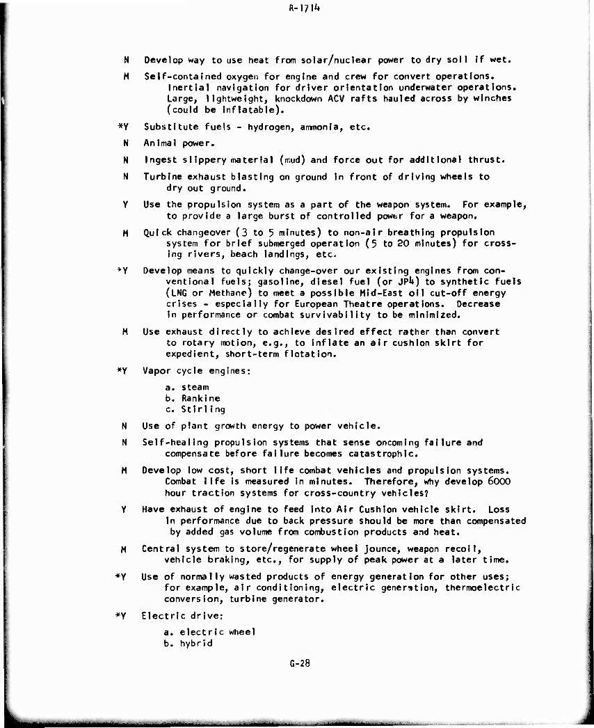
R-l?!^
N Develop way to use heat from solar/nuclear power to dry soil ff wet.
M Self-contained oxygen for engine and crew for convert operations. Inertlal navigation for driver orientation underwater operations. Large, lightweight, knockdown ACV rafts hauled across by winches (could be Inflatable).
*Y Substitute fuels - hydrogen, ammonia, etc.
N Animal power.
N Ingest slippery material (nr.ud) and force out for additional thrust.
N Turbine exhaust blasting on ground In front of driving wheels to dry out ground.
Y Use the propulsion system as a part of the weapon system. For example, to provide a large burst of controlled power for a weapon.
M Quick changeover (3 to 5 minutes) to non-air breathing propulsion system for brief submerged operation (5 to 20 minutes) for cross- ing rivers, beach landings, etc-
+Y Develop means to quickly change-over our existing engines from con- ventional fuels; gasoline, dlesel fuel (or JPk) to synthetic fuels (LNG or Methane) to meet a possible Mid-East oil cut-off energy crises - especially for European Theatre operations. Decrease In performance or combat survivabiIity to be minimized.
M Use exhaust directly to achieve desired effect rather than convert to rotary motion, e.g., to Inflate an air cushion skirt for expedient, short-term flotation.
*Y Vapor cycle engines:
a. steam b. Rankine c. StirlIng
N Use of plant growth energy to power vehicle.
N Self-healing propulsion systems that sense oncoming failure and compensate before failure becomes catastrophic.
M Develop low cost, short life combat vehicles and propulsion systems. Combat life is measured in minutes. Therefore, why develop 6000 hour traction systems for cross-country vehicles?
Y Have exhaust of engine to feed Into Air Cushion vehicle skirt. Loss In performance due to back pressure should be more than compensated by added gas volume from combustion products and heat.
M Central system to store/regenerate wheel jounce, weapon recoil, vehicle braking, etc., for supply of peak power at a later time.
*Y Use of normally wasted products of energy generation for other uses; for example, air conditioning, electric generation, thermoelectric conversion, turbine generator.
*Y Electric drive:
a. electric wheel b. hybrid
G-28
^■M
R-m'»
M Linear Induction motor.
M Increased use of turbine power.
Y Magnetic suspension and drive.
N Propulsion systems that don't have to Idle when not providing power.
*Y Reduce total power or propulsion signature noise, IR, gases, light.
*V Stored energy for peak power requirements:
a. Flywheel b. Battery c. Spring d. Accumulator e. Crew
Y Transmission of energy from a central point to vehicles in the field by wlreless means.
Y Solar energy propulsion system.
M People power for peak demand requirements.
Modular Design
M Multiply linked propulsion systems. Items that can be added or removed that have powered traction.
Driver Aids
Y Mobility failure sensing feature, to provide override and optimum drive parameters.
N Elimination of Instrumentation. Do away with oil pressure gage, coolant temperature, engine RPM, tail pipe temperature.
N Automatic engine Interrogation and evaluation portable diagnostic system.
M Man-vehicle Interface - training devices that teach driver how much driving stress they can take.
Y Driver training technology must be improved. Driver Is usually the limiting factor,
N TV or periscope In snorkel for bottom crawling vehicles In deep fording.
G-29
lilW-WUlHfc
■ li - - - ■- -
R-l/l1»
Team No. 3
Basic Mission:
Envlronments;
Team Members: Patek, Chairman
HamIIton
Czako
Spanski
Douglas
Duane
Bronner
Suspension Systems
River Crossing
SIippery Surfaces
Urban Areas
Wheel Concepts
Y Fibreglass parabolIc wheel.
N Combine paddle wheel propulsion with conventional wheels.
Remote Systems
M Deceiver vehicle to clear mines.
Y Remote control vehicle eliminates driver limit on mobility.
Air/Ground Systems
N Auxiliary helicopter kit for river or large obstacle crossing capa- bility.
N individual means of transportation for the soldier, i.e., flying belts.
Traction/Flotation Aids
N Slide (make it slippery) vehicles around tight city corners.
Y Numerous separate rubber bands to act as tracks (power belts).
H Non-mechanical drive in track vehicles to reduce noise.
G-30
MM
R-171^
Y Use "Voth=Schneider" (cycloidal) propeller in bottom of vehicle.
Y Track pads or tires that have variable friction-ground pressure capabilities either by sweating sticking fluid or changing shape and foot print:
a) cone type wheel b) foam or liquid filled c) liquid tire chain d) central tire inflation e) spiked track pads f) pneumatic track pads g) discardable track pad width extensions h) flair out footing i) brush-I ike wheels
Y Band-type track for heavy GVW (60,000 lb to 120,000 lb) vehicles to reduce vibrational power losses.
M Walking vehicle with suction cups to overcome siIpperiness.
New Vehicle Forms
M Have moving ballistic surfaces to improve or change penetration capability.
N Obtain ballistic projection by pillow or marshmaHow effect (absorb shock of projectile). Allows weight reduction.
Y Encapsulate driver and or cargo in positionally stabilized shock Insulated compartment.
Y Pitch control for crossing bombcraters In streets.
N Vehicle capable of turning on its side and driving forward (thru narrow openings).
Y Articulated Combat Vehicles overcome the inherent length-to-width ratio problem and allows longer narrower vehicle.
M Eliminate turret, gun positioning through variable height suspension.
M Jet Assist/Hybrid Vehicle.
M Marsh Screw/wheel/track hybrid vehicle.
Y Lightweight air cushion wheel or track vehicle hybrid.
M Floor of hull becomes two large walking feet to assist in soft soil.
H Suspension capable of automatically changing its chassis position to affect weight distribution and CG transfer capability.
Y Variable width vehicle. Possible elastic side walls external to armor for storing fluid vehicle requirements. Allows squeeze through tioht spaces.
M Wheels posltionaMe fore and aft to shorten or lengthen wheel base.
M Develop 2 or 3-wheel type vehicle suspension.
N Boat shaped body to improve water speed.
G-31
- ■ _.
R-l?^
i
M Hybrid vehicle using archlmedes screw for water propulsion and exiting of water.
Y Special-purpose, cheap, lightweight vehicles.
N Crab steer capability.
M Walking device - second generation - force feedback controlled by numan operator.
External Mobility Aids
N Use temporary Interlocking aircraft landing mats on river banks.
Y Spray bank with tractive or hardening substance.
Y C carpet-like device which would cover weak soil areas.
N Quickly detach cargo to lighten vehicle and drag over on a cable under water after vehicle crosses.
N Special paint to reduce water resistance.
M Inflatable planing board to increase water speed.
Y Use ACV barge, no propulsion system. Carry across vehicle by barge on winch cable.
M Harpoon guns or bazooka to throw line and winches to aid river crossings.
Y Increase buoyancy and stability with air cushion outriggers.
Y Air- or fluid-cushion suspension assist either built-in or add-on kit form for total vehicle weight or partial support.
Y Inflatable balloon pontoons pressurized from central air system.
N Balloon inflation with lithium hydride and water to generate hydrogen.
Y Water jet to wash away river bank.
Y Air cushion bridge-run out sections for water crossing; power source ashore and independent of run-out sections.
N High speed pu'verizer kit and jet dispenser to fill craters.
Y Quick-hardening foam cut to fill holes or cut sIIpperiness, or allow crossing mines, fields.
N Helium balloon kits for soft soil or river crossing.
N Use rocket-emplaced anchor with power winch to repetitively haul vehicles across slippery surfaces.
M Add J.A.T.O. for exiting onto slippery surfaces. I
G-32
MMMto^ ^.MMflMi
Power Sources
M Cryogenic (superconductivity) motors for small size, large power output.
N Use gun recoil energy to give impulse propulsion to cross difficult obstacles. Use special non-projectile charge.
M Electromagnetic propulsion and suspension.
Y Linear electric motors with ground-laid cable.
Modular Design
Y Design detachable cab pod which can be used as a controller for any vehicle.
Y Plug in; plug out throw away (modular) suspension to reduce weight and ease of maintenance.
Driver Aids
Y Bourden tube-type spring to change spring rate by changing the shape of cross-section.
M Flexible drive shaft for independent suspension to Increase wheel travel through elimination of u-joint angular limits.
M Fluldic control devices for automatic terrain sensing springing and damping.
M Mini-Computer for suspension spring and damping control.
Y Boron spring elements (Hi strength, low volume).
Y Inertia control sensing system for suspension to cause it to react in advance of an obstacle,
M Suspension rate adjustable by the driver simply and quickly while moving (dial-the-ride).
Y High wheel travel (more than 12") suspension for small (jeep size) vehicles.
M Control console with push-button operation of the vehicle. Example: 50 mph, ^0 mph button.
Y Improved electrically heated windows to enhance visibility.
Y Dry suspension - no fluid medium in the damping element.
Y All rubber suspension - maintenance free, quiet, cheap.
Y Automatically adjustable damping rate controlled by ride severity measurement (automatic tuning away from resonance range).
Y Air over hydraulic suspension system whose characteristic is con- trolled by the dynamic wheel (road wheel) load variation.
H Controls have pictorial description of use rather than verbal for easier identification.
G-33
MflMB tmmt - - ■-.
n— ■ / IT
M Isolated sound proof and vibration fre« personnel pod or compartment, rejectable for easy, rapid escape. Installable In every combat vehicle to make all vehicles operable by a single person. A command module idea.
Y Control elevation of operator's position for rough terrain. Improved observation.
Y Variable height suspension.
Y Highly improved seating with adjustable springing and damping; resilient bump-stops.
N Extendable fibre optics for looking around corners.
Y Variable rate torsion bars to provide mechanical variable rate systems or small compact configuration»
Y Hydromechanical strut as suspension element. Includes newly developed material (elastomesic) to fulfill multiple and partially contra- dictory measurements which cannot be satisfied with present hydraulic fluids.
G-31*
mam Mki -- - ■ -
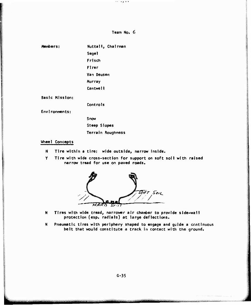
Team No. 6
Members: Nuttall, Chairman
Segel
Frisch
Flrer
Van Deusen
Murray
Cantwell
Controls
Snow
Steep Slopes
Terrain Roughness
Wheel Concepts
N Tire within a tire: wide outside, narrow inside.
Y Tire with wide cross-section for support on soft soil with raised narrow tread for use on paved roads.
Basic Mission:
Environments:
y *?F,r f**^
N Tires with wide tread, narrower air chamber to provide side-wall protection (esp. radials) at large deflections.
N Pneumatic tires with periphery shaped to engage and guide a ccntinuous belt that would constitute a track in contact with the ground.
G-35
~di
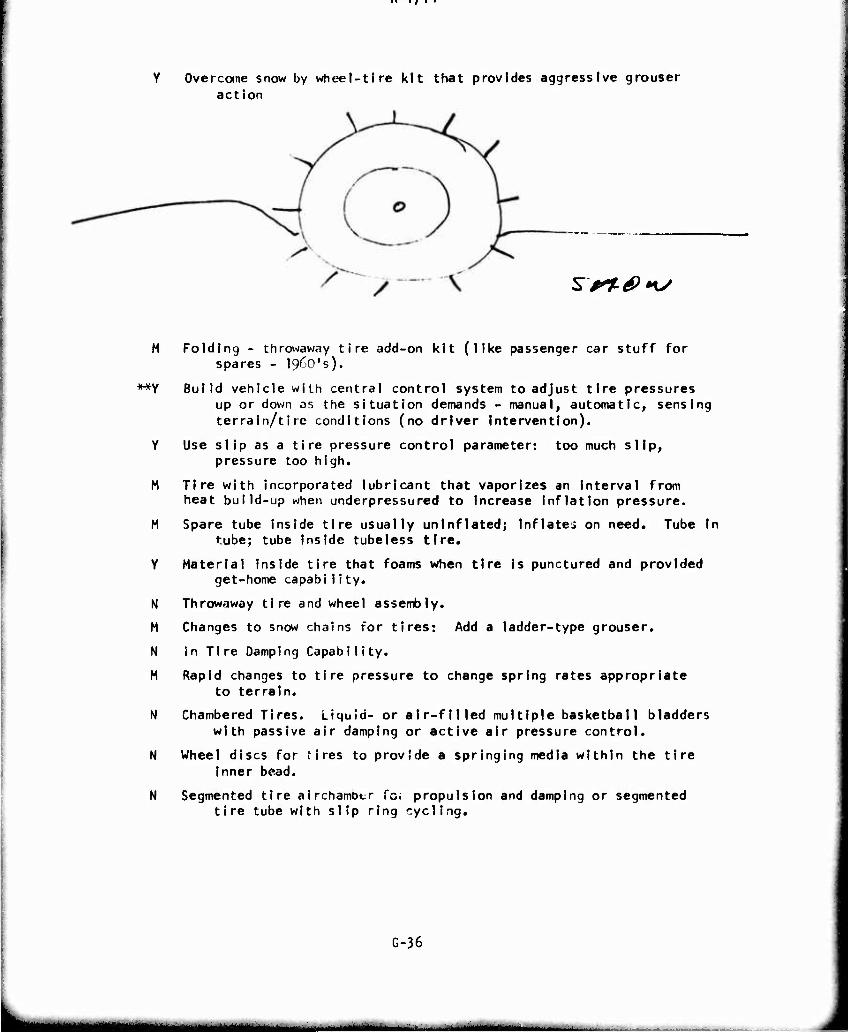
Overcome snow by wheel-tire kit that provides aggressive grouser action
sr%0»w
M Folding - throwaway tire add-on kit (like passenger car stuff for spares - ^O's).
**Y Build vehicle with central control system to adjust tire pressures up or down os the situation demands - manual, automatic, sensing terrain/tire conditions (no driver Intervention).
Y Use slip as a tire pressure control parameter: too much slip, pressure too high.
M Tire with Incorporated lubricant that vaporizes an Interval from heat build-up when underpressured to Increase Inflation pressure.
M Spare tube Inside tire usually uninflated; Inflates on need. Tube Ir tube; tube Inside tubeless tire.
Y Material Inside tire that foams when tire Is punctured and provided get-home capability.
N Throwaway tire and wheel assembly.
M Changes to snow chains for tires: Add a ladder-type grouser.
N in Tire Damping Capability.
M Rapid changes to tire pressure to change spring rates appropriate to terrain.
N Chambered Tires. Liquid- or air-filled multiple basketball bladders with passive air damping or active air pressure control.
N Wheel discs for 'Ires to provide a springing media within the tire Inner bead.
N Segmented tire airchambtr fo. propulsion and damping or segmented tire tube with slip ring cycling.
G-36
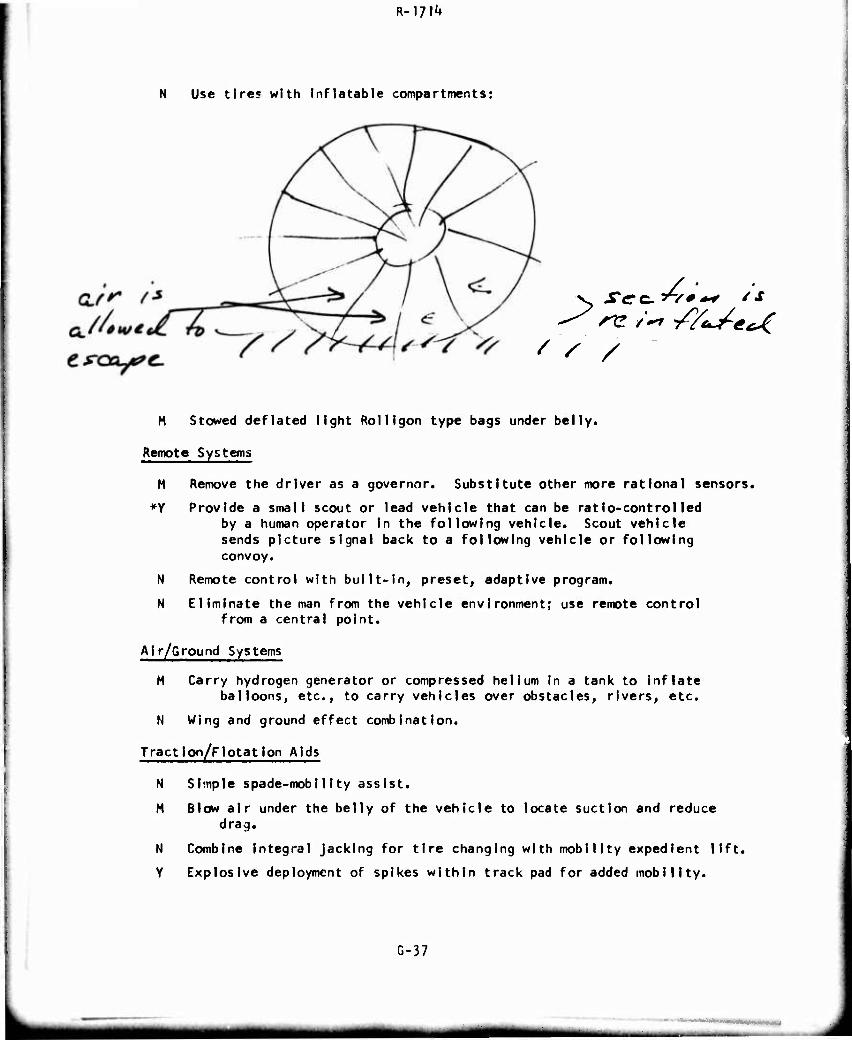
R-l?^
N Use tires with Inflatable compartments:
' ' /
H Stowed deflated light Roll igen type bags under belly.
Remote Systems
M Remove the driver as a governor. Substitute other more rational sensors.
*Y Provide a small scout or lead vehicle that can be ratio-controlled by a human operator In the following vehicle. Scout vehicle sends picture signal back to a following vehicle or following convoy.
N Remote control with built-in, preset, adaptive program.
N Eliminate the man from the vehicle environment; use remote control from a central point.
Air/Ground Systems
M Carry hydrogen generator or compressed helium in a tank to inflate balloons, etc., to carry vehicles over obstacles, rivers, etc.
N Wing and ground effect combination.
Traction/Flotation Aids
N Simple spade-mobility assist.
M Blow air under the belly of the vehicle to locate suction and reduce drag.
N Combine integral Jacking for tire changing with mobility expedient lift.
Y Explosive deployment of spikes within track pad for added mobility.
G-37
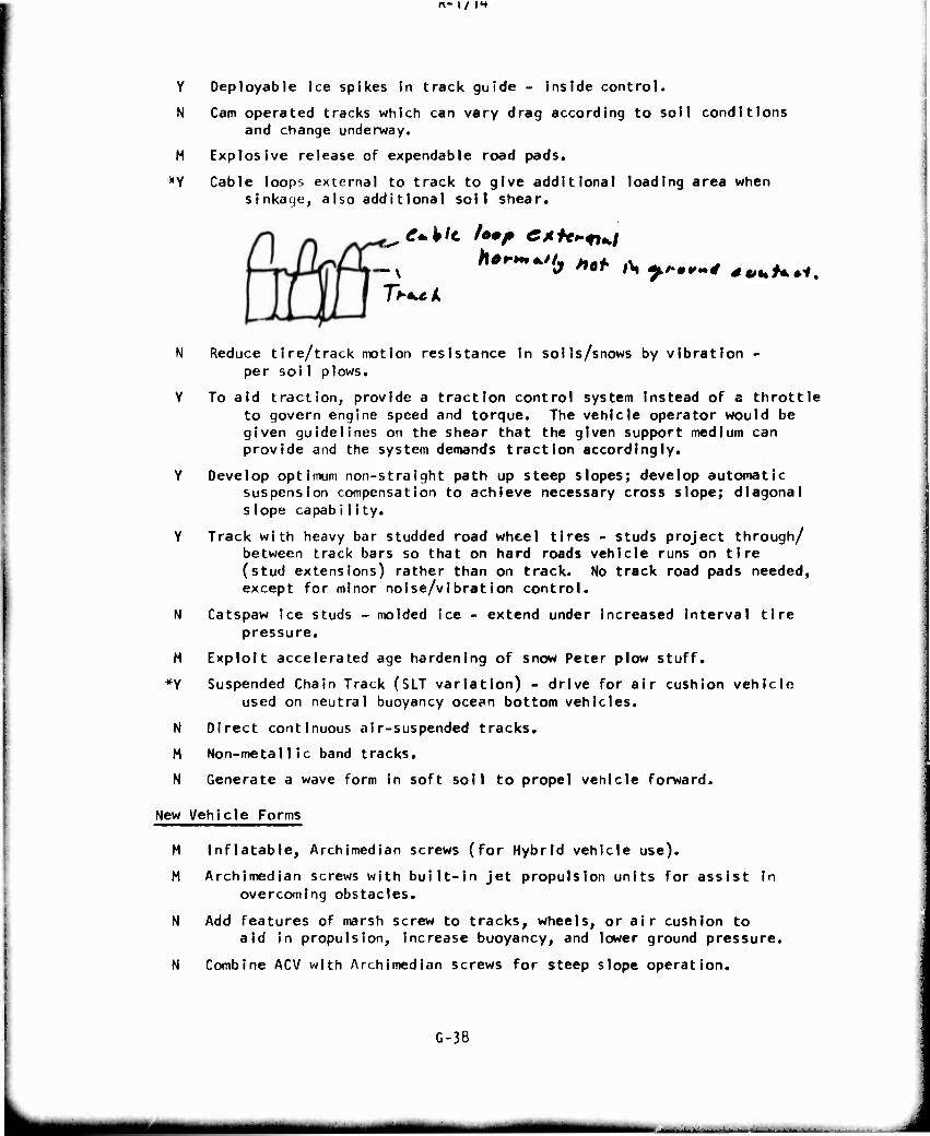
r\- 1/ it
Y
N
M
*Y
N
Y
M
»Y
N
M
N
Oeployable Ice spikes in track guide - inside control.
Cam operated tracks which can vary drag according to soil conditions and change underway.
Explosive release of expendable road pads.
Cable loops external to track to give additional loading area when sinkacje, also addi t lonal soil shear.
e+klc Um? CAfe^^t^i /t**-***.//,
Tf^ck b Hot l\ ff*»* *v%>f**i.
Reduce tire/track nwtlon resistance In soils/snows by vibration - per sol 1 plows.
To aid traction, provide a traction control system instead of a throttle to govern engine speed and torque. The vehicle operator would be given guidelines on the shear that the given support medium can provide and the system demands traction accordingly.
Develop optimum non-straight path up steep slopes; develop automatic suspension compensation to achieve necessary cross slope; diagonal slope capability.
Track with heavy bar studded road wheel tires - studs project through/ between track bars so that on hard roads vehicle runs on tire (stud extensions) rather than on track. No track road pads needed, except for minor noise/vibration control.
Catspaw ice studs -molded ice - extend under increased Interval tire pressure.
Exploit accelerated age hardening of snow Peter plow stuff.
Suspended Chain Track (SLT variation) - drive for air cushion vehicle used on neutral buoyancy ocec>n bottom vehicles.
Direct continuous air-suspended tracks.
Non-metallic band tracks.
Generate a wave form in soft soil to propel vehicle forward.
New Vehicle Forms
M Inflatable, Archimedian screws (for Hybrid vehicle use).
M Archimedian screws with built-in jet propulsion units for assist in overcoming obstacles.
N Add features of marsh screw to tracks, wheels, or air cushion to aid in propulsion, increase buoyancy, and lower ground pressure.
N Combine ACV with Archimedian screws for steep slope operation.
G-38
H^riH HMMB
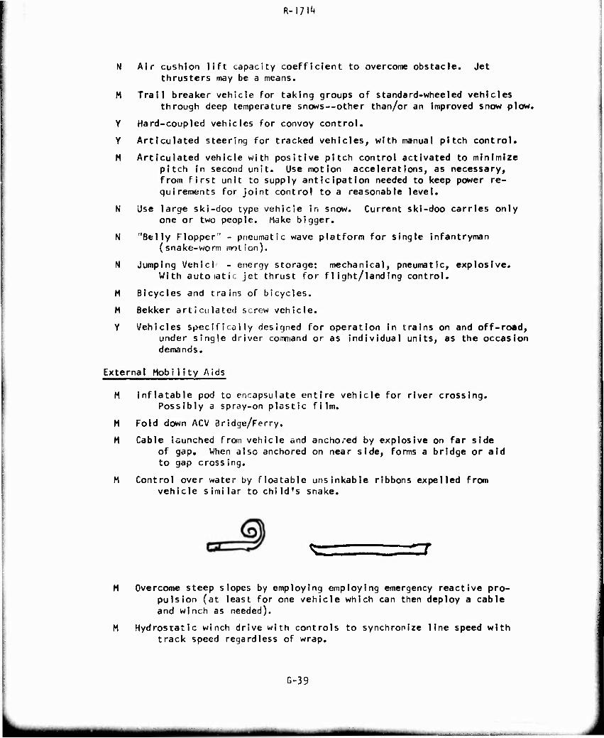
R-l?!^
N Air cushion lift capacity coefficient to overcome obstacle. Jet thrusters may be a means.
M Trail breaker vehicle for taking groups of standard-wheeled vehicles through deep temperature snows—other than/or an improved snow plow.
Y Hard-coupled vehicles for convoy control.
Y Articulated steering for tracked vehicles, with manual pitch control.
M Articulated vehicle with positive pitch control activated to minimize pitch in second unit. Use motion accelerations, as necessary, from first unit to supply anticipation needed to keep power re- quirements for joint control to a reasonable level.
N Use large ski-doo type vehicle In snow. Current ski-doo carries only one or two people. Hake bigger.
N "Belly Flopper" - pneumatic wave platform for single infantryman (snake-worm motion).
N Jumping Vehlcl - energy storage: mechanical, pneumatic, explosive. With autoiatic jet thrust for flight/landing control.
M Bicycles and trains of bicycles.
M Bekker articulated screw vehicle.
Y Vehicles specifically designed for operation in trains on and off-road, under single driver command or as individual units, as the occasion demands.
External Mobility Aids
M Inflatable pod to encapsulate entire vehicle for river crossing. Possibly a spray-on plastic film.
M Fold down ACV Bridge/Ferry.
M Cable launched from vehicle and anchored by explosive on far side of gap. When also anchored on near side, forms a bridge or aid to gap crossing.
M Control over water by floatable unsinkable ribbons expelled from vehicle similar to child's snake.
Overcome steep slopes by employing employing emergency reactive pro- pulsion (at least for one vehicle which can then deploy a cable and winch as needed).
Hydrostatic winch drive with controls to synchronize line speed with track speed regardless of wrap.
G-39
tm^mm
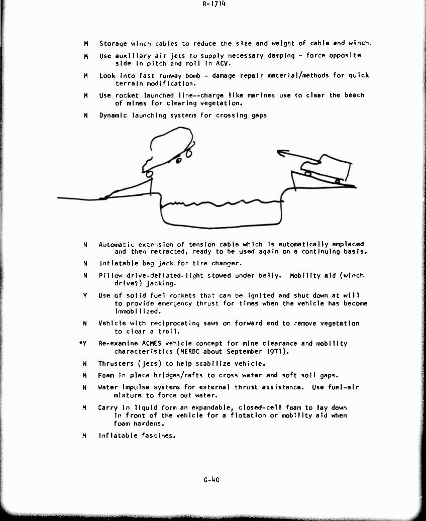
R-\7\k
M Storage winch cables to reduce the sJze and weight of cable and winch.
M Use auxiliary air jets to supply necessary damping - force opposite side in pitch and roll in ACV.
M Look Into fast runway bomb - damage repair material/methods for quick terrain modification.
M Use rocket launched line—charge like marines use to clear the beach of mines for clearing vegetation.
N Dynamic launching systems for crossing gaps
N Automatic extension of tension cable which Is automatically emplaced and then retracted, ready to be used again on a continuing basis.
N Inflatable bag jack for tire changer.
N Pillow drive-deflated-light stowed under belly. Mobility aid (winch drive?) jacking.
Y Use of solid fuel rcKkets thöt can be ignited and shut down at will to provide emergency thrust for times when the vehicle has become immoblIized.
N Vehicle with reciprocating saws on forward end to remove vegetation to clear a trai I.
♦Y Re-examine ACMES vehicle concept for mine clearance and mobility characteristics (MERDC about September 1971).
N Thrusters (jets) to help stabilize vehicle.
M Foam in place bridges/rafts to cross water and soft soil gaps.
N Water Impulse systems for external thrust assistance. Use fuel-air mixture to force out water.
M Carry In liquid form an expandable, closed-cell foam to lay down In front of the vehicle for a flotation or mobility aid when foam hardens.
M Inflatable fascines.
G-^O
mm — -
R-iyi't
Power Sources
M Use of smaller engines, supplemented by energy storage device (e.g., flywheel) to handle peak power demands.
N Gas Pop Gun to accelerate engines.
M Friction Drive System.
N Source of energy coupled with mechanical springs providing an impulse to lift and propel one man through the air.
Driver Aids
M Crew ejection system for tanks.
Y Proper seat belts - restraints.
Y Roll bars for vehicles.
N Active suspension to control roll/pitch.
M Automatic Navigation System based upon area surveillance system which selects path of least mobility obstruction!
N Air droppable navigation aids/sensors with communication link to driver for automatic route optimization.
M Terrain intelligence by satellite to avoid impassable areas.
M Pathfinder vehicle as a terrain sensor.
N Man in ejection return capsule to observe terrain and remotely guide vehicle.
M Use advanced electronic technology to place small computers in a vehicle that determine the optimum suspension parameters for the environment being negotiated. Vehicle has an adjustable suspens ion.
Y Hook vehicles together in convoy with electrical wires and auto- matic speed controls.
H Fluidics Technology to be used in design of control systems. (Similar to technology used in Helicopter Automatic Stabi- Iization Systems).
M Automatic Speed Control based upon sensing vehicle motion and/or "forecasting" (sensing) terrain obstacles in front of the vehicle.
M Better performance inclination at driving position - Digital Readout ■ including sensing of terrain conditions (soil strength, etc.).
H Sensor display systems to driver, including and/or other non-visual senses, such as odor, to provide information on the operating state, e.g., is a component about to fail.
N Eliminate as many control functions as possible by use of automatic shut downs, power limiters or audio warnings.
G-41
i^HMM
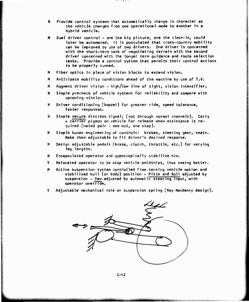
N Provide control systems that automatically change In character as the vehicle changes from one operational mode to another In a hybrid vehicle.
M Dual driver control - one the big picture, one the close-In, could later be automated. It Is postulated that cross-country mobility can be Improved by use of two drivers. One driver Is concerned with the short-term task of negotiating terrain with the second driver concerned with the longer term guidance and route selection tasks. Provide a control system that permits their control actions to be properly summed.
M Fiber optics In place of vision blocks to extend vision.
M Anticipate mobility conditions ahead of the machine by use of T.V.
M Augment driver vision - high/low line of sight, vision intensifler.
N Simple precheck of vehicle systems for reliability and compare with upcoming mission.
N Driver conditioning (booze?) for greater ride, speed tolerance, faster responses.
N Simple secure distress signal; (not through normal channels). Carry a carrier pigeon on vehicle for release when assistance Is re- quired (mated pair - one out, one stay).
N Simple human engineering of controls: brakes, steering gear, seats. Make them adjustable to fit driver's desired response.
M Design adjustable pedals (brake, clutch, throttle, etc.) for varying leg lengths.
N Encapsulated operator and gyposcopically stabilize him.
Y Relocated operator to be dtop vehicle amidships, thus seeing better.
M Active suspension system controlled from sensing vehicle motion and stabilized hull (or body) position - Pitch and Roll adjusted by suspension - Yaw adjusted by automatic steering Input, with operator override.
Y Adjustable mechanical rate on suspension spring (Ray MacHenry design).
^^
l-hl
,., ,,„ ul^^mm
R-I7I4
M Allow a vehicle to follow automatically a preceeding vehicle. Lock on (Light - IR Seismiz) to control speed and/or steering. Alternate - driver Indication - of closing rate distance between vehicles. Speed.
M Simple indicator system that tells the driver how far he Is behind next vehicle in convoy. Narrow band rear light photo cell forward on vehicle may be automated to red, green, yellow idiot light.
Y Simple control of uncoupled trains/convoys for manpower reduction.
H Siesmic sensors for convoy control.
Y If the vehicle has no suspension, rough terrain traversal can be Improved by employing dynamic vibration absorbers, i.e., allow a small mass to displace a large amount at the proper natural frequency.
N Pleasure center stimulation of man and beast with automatic remote or programmed control.
H Design seats more comfortably and easier to adjust.
G-iO
———« mi mtmrntt
R-I/IH
2 October \972
APPENDIX H
MASTER AGENDA
MONDAY, October 16
1600-2200
1600-1800
1800-
Arrival and check in - Ehrlich, Cantwell and Crane
Briefing of team chairmen — McNeill, Magistro
Orientation of team chairmen — ground rules of workshop.
Distribute packages.
Discuss idea-spurring questions and how to use them.
Discuss briefing document and objectives of workshop.
Dry run of typical workshop.
Typing — Between 1800 and \0kS Tuesday, need to type up:
Idea spurs.
Improved briefing document.
TUESDAY, October 17
0800-0910 Welcome, Opening Remarks - Ehr 1 ich, Cantwell, Ziem
0S]0-09kS Workshop orientation and charge -McNeill
SI ide show.
Handouts.
Brainstorming procedure.
09^5-1015 Break — Coffee and rolls in auditorium
I015-II30 Briefings - Dugoff and Nuttall
Terrain descr'ption.
Definition of the mobility problem.
1130-1200 Team Organization — Team Chairmen
Divide into six teams.
Find rooms.
Set up work area.
Distribute first briefing document.
Supply idea spurs to chairmen.
Get-acquainted between team members.
Quick look at problem before lunch (if time allows)
H-l
m—m

R-\J\k
Tuesday, October 17 (continued)
1200-1300 Lunch
Sit by teams.
Continue discussions while waiting to be served.
I3OO-l'+30 Workshop Session I
Each team 7-8 members.
Assign an area for each team.
Objective: Idea output of at least 70 ideas per session.
Ideas to be placed on S'^S" cards.
What are the possible future (1980-1990 and beyond) technological advances which might be translated into an improvement in mobility from a standpoint of;
1. Man/Machine/Environment interface?
2. Vehicle morphology (shape and arrangement)?
3. Traction systems?
*+. Propulsion systems?
5. Suspension systems of ground vehicles?
6. Control systems?
1U30-I600 Typing up all ideas generated in Session I and distribute
them to all participants. Estimate load: 500 lines.
1^30-1530 Briefing - Marsh and Patek
Vehicular Components.
I530-I5i*5 Break
15^5-1600 Techniques Review — McNei11, Magistro, Ranger, Team Chairmen
Review Techniques.
Pinpoint Procedure Weaknesses.
Take Corrective Action.
1600-1700 Workshop Session II ^
Same teams as Session I.
Review distributed material, especially ideas of other groups.
Seek 90-100 ideas per team.
"In light of the previous briefing and a review of the ideas generated by other qroups, what might you add to the list you or other Committees generated in Session I?"
H-2
«MBaBMSi
R-I711*
TUESDAY. October 17 (continued)
1700-1730 Critique and Summary (Team Members)
Develop written summary of day's activities.
Critique of technique, methods, procedures.
Organize cards generated into logical groupings.
Suggest pairs of members do each of the three above tasks.
Team Chai rmen
Team Chairmen and Steering Committee
Evaluate progress.
Suggest improvements.
Re-define charge.
I73O- Typing
Type up and distribute ideas from Session II by 0390 Wednesday.
1830-1930 Get-Acquainted Cocktai I Party - University I
WEDNESDAY. October 18
0830-0930 Briefings - Fierer
Soviet Vehicles.
0930-1200 Workshop Session IN
Assign 2 or 3 mobility impediments per team.
Looking for at least 200 ideas per team.
Take break at 1030 for coffee and pastry in workshop rooms.
"How might these new technological developments. In coordi-
nation with existing technology, be applied to attack the
mobility problems presented by:
1. Obstacles? 2. River Crossings? 3. Snow? k. Soft Soil? 5. Slippery Surfaces? 6. Steep Slopes 7. Dense Vegetation? 8. Urban Areas? 9. Terrain Roughness?
H-3
■■■■■HHMBaiHMMtaMMka«k^»_<^MBBMa>a._^MaMiiaMa
WEDNESDAY. October 18 (continued)
Consider the following approaches:
1. Wheels 2. Tracks 3. Air Cushions l*. Unconventional, novel or new systems 5. Hybrid Combinations of the Above 6. Add-on Kits to the Above 7. External Mobility Aids (winches, portable mats,etc.)"
1130-1200 Progress Review — Team Chairmen and Steering Committee
Turn over last half hour of Session I I I to Members to con- tinue along.
Half-way progress review and recommendations.
1200-1300 Lunch
Have Teams eat together (less chairmen).
Team Chairmen and Steering Committee eat together to con- tinue discussions.
0100- Typing
Begin typing up results of Workshop Session III.
UOO-U^S Briefing - Nuttall
Historical approaches to the Mobility Problem.
13^5-1600 Workshop Session IV
Continuation of Session III.
Looking for at least 100 ideas per team.
Last half hour develop evaluation criteria.
IM+5-I500 Break
1500-1600 Evaluation Briefing - EhrlIch
Team chairmen meet together.
Discuss evaluation technique.
Discuss trade-off technique.
Discuss ranking criteria.
Discuss Army requirements.
1500- Typing
Complete typing up Ideas from Sessions III and IV by 0830 Thursday.
H-U
R-17^
WEDNESDAY. October 18 (continued)
I600-I700 Rating Check List - Steering Committee
Reconsider Rating Check - list previously developed.
Select Ad Hoc Team.
1600-1700 Critique — Team Chairmen
General review and critique of program.
1600-1700 Summary — Team Members
Review and organize work of the day.
Prepare a written summary of results.
I7OO- Have Rating Sheets typed up and run off by 1100 Thursday.
I83O- ? Dinner/Theater, Village Barn Theater (optional).
THURSDAY, October 19
0830-1100 Workshop Session V
Same groups as for Workshop III and IV.
Coffee break at 1000 in workshops.
Look for 35 ideas per team.
How may the results of the preceding Sessions be applied
to attack the mobility problems associated with the
following missions:
1. Logistical (tactical support in the combat area)?
2. Combat (transport of a weapon or combat troops on the battlefield)?
3. Command and Reconnaissance (transport of lightly armed personnel at high speed over a wide variety of terrain)?
Take cognizance of the factors requiring the Army to make
multiple usage of P.s vehicle fleet in a wide range of
environment and for the use of each vehicle in general-
purpose assignments. r
Also consider the pressures of cost, reliability, maintain-
ability, weight, complexity, space, east ofX ope rat ion, etc,
H-5
mgtmma^mmmmmtmmmmtmm^mmmtmm
1100-1200 Evaluation Session
Evaluation of concepts employing criteria and score-sheet
developed on Wednesday.
IIOO-IUOO Type up results of Workshop V
1200-1300 Lunch
Seating for lunch mixed up — do not sit by teams.
1300-1*400 Workshop Session Vl
Same teams as Sessions Ml-V.
Restatement of the mobility problem.
'What non-hardware approaches may also be suggested to improve
the overall operational mobility of our field Army?"
]kQ0~\kkS Briefing - Jones
Current Army Vehicle Fleet and Drawing Board Plans.
lUOO-1700 Type up results of Workshop VI
1^5-1615 Workshop Session VII
Same teams as Sessions I II-VI.
Idea improvement.
Break at 1500 in workshops.
"Take the best ideas so far presented and see how they might be improved upon."
1615-1700 Report Preparation
Prepare written summary of activities.
Prepare written critique of activities.
Prepare 15-minute presentations for Friday.
Discuss conclusions and recommendations to be forth- coming from workshops.
I83O- ? Banquet
FRIDAY. October 20
0830-100 Fifteen-minute team reports — Ehr'ich
0830-1200 Type up results of Workshop Session VII, written summaries and cri t iques.
1000-1015 Break — Make arrangements for return to airport.
1000-1200 Open discussion and development of conclusions — Ehrlich.
H-6
MMMMM