distributed by: ktÜl€¢ full-speed dynamic clutch-overrun testing • differential-speed...
TRANSCRIPT
AD-782 814
TEST RESULTS AND TECHNOLOGY DEVELOP- MENT REPORT: HLH/ATC (HEAVY LIFT HELICOPTER/ADVANCED TECHNOLOGY COM- PONENT) TRANSMISSION OVERRUNNING CLUTCH
Nelson J. Ayoub, et al
Boeing Vertol Company
Prepared for:
Army Air Mobility Research and Development Laboratory
April 1974
DISTRIBUTED BY:
KTÜl National Technical Information Service U. S. DEPARTMENT OF COMMERCE 5285 Port Royal Road. Springfield Va. 22151

IlnelaHfiifioH SECUMITV CLASSIFICATION OP THIS PAGE (Whit Dmtm Bnlmnd)
REPORT DOCUMENTATION PAGE I. NEPORT NUMBCM
USAAMRDL-TR-74-17
2. GOVT ACCESSION NO. 3- RECIPIENT'S CATALOG NUMBER
4. TITLE f«n<» Sub«tl.)
Test Results and Technology Development Report—HLH/ATC Transmission Overrunnning Clutch
T. AUTHORS
Nelson J. Ayoub W. G. Perin
S. PERFORMING ORGANIZATION NAME AND ADDRESS
Boeing Vertol Company, A Division of The Boeing Company, P. 0. Box 16858 Philadelphia, Pennsylvania 19142
IS. DISTRIBUTION STATEMENT foKM. R«por(;
Approved for public release; distribution unlimited.
II. CONTROLLING OFFICE NAME AND ADDRESS
U, S. Army Aviation Systems Command P.O. Box 209, Main Office St. Louis, Missouri 63166
TJ MONITORING AGENCY NAME t ADORESV" illllnmtl Imm Conlrolllnt OMe*)
Eustis Directorate, U.S. Army Air Mobility Research and Development Laboratory Fort Eustis, Virginia 23604
4.D TM &£ READ INSTRUCTIONS
BEFORE COMPLETINO FORM
S. TYPE OF REPORT A PERIOD COVERED
S. PERFORMING OR6. REPORT NUMBER
T301-10222-1 S. CONTRACT OR GRANT NUMBER*.,)
DAAJ01-71-C-0840{P40)
10. PROGRAM ELEMENT. PROJECT, TASK AREA • WORK UNIT NUMBERS
12. REPORT DATE
April 1974 II. NUMBER OF PAGES
IS. SECURITY CLASS, (ol Ihlm report;
Unclassified IS«. OECLASSIFICATION/DOWNCRADING
SCHEDULE
17. DISTRIBUTION STATEMENT (ol Ml* abtltmcl tnttnd In Bloc» 70, II dllltrml Iram Rmpart)
It. SUPPLEMENTARY NOTES
JL. It. KEY WORDS (Ccnllnut on nvotto oldo II nocoooory «' Homily by Hock numbor)
Heavy lift helicopter Clutches Drives
10. ABSTRACT rContlnu* an nrmoo nHo II nocomoory mnt lOonllly hy block numb—)
This report presents the results of an evaluation test program to develop the optimum sprag engine/transmission clutch for use in the Heavy Lift Helicopter (HLH) drive system.
The design operating conditions were 3,795 ft-lb of torque transmitted at 11,500 rpm. Three clutch configurations with differing design philosophies were first subjected to a pre- ^.L, liminary evaluation j ~j*_
DO | jAlTn 1473 EOtTIOH OF I NOW M ft OBSOLETE «
"NATIONA! TFCHNICAI. / • INFORMATION SERVICE
., t ■■'■■■■ ■
... • ■ VA .■ :■ ■
Unclasaified SECURITY CLASSIFICATION OF THIS PAGE (HÜ OMa Bnlorod)

Unclaasified ttCUWITY CLAtliriC«TIOM Of TMI1 *Mt(Whm DM» MiMmä)
Block 20. Abstract - continued.
• Borg-Warner X137661—Design A
• Borg-Warner X1376 75—Design B
• Formsprag CL-41802—Design C
As a result of this preliminary evaluation consisting of over- running and differential-speed testing, the Borg-Warner design X137675 was judged to have the best performance. Accordingly, this design was then optimized (Borg-Warner design X137920, Design D) and subjected to a more comprehensive test program:
• Full-Speed Dynamic Clutch-Overrun Testing
• Differential-Speed Clutch-Overrun Testing
• Static Cyclic Torque Fatigue Testing
• Static Overload Testing
• 50-Hour Endurance Testing
Drag torque, oil temperatures, and oil flow were monitored during the dynamic testing.
The optimized Design D Borg-Warner X137920 clutch configura- tion successfully met all HLH Advanced Technology Component (ATC) design requirements.
J&. Unclassified
MCUNITV CLAMiricATiON or THIS p*oer«h«i OM< inim«
Eustis Directorate Position Statement
The objective of this effort was to conduct an extensive test and evaluation program to develop an optimum sprag clutch for use in the Heavy Lift Helicopter (HLH) drive system.
The clutch configurations tested incorporated many of the design recommendations published in USAAMRDL Technical Report 72-49, "Sprag Overriding Aircraft Clutch' As a result of these recommendations and those generated during the program, a successful clutch design evolved. The resulting clutch configuration was thoroughly tested and met all the HLH drive system design requirements.
This directorate concurs with the conclusions presented herein.
The technical monitor for this effort was Mr. Wayne A. Hudgins, Heavy Lift Heli- coper Project Office, Systems Support Division.
DISCtAIMERS
Tlw findingi in this report art not to bt eonitruad as an official Department of the Army position unless so dtsignated by other authorized document*.
When Government drawings, specifications, or other data are used for any purpose other than in connection with a definitely related Government procurement operation, the United States Government thereby incurs no responsibility nor any obligation whatsoever; and the tact that the Government may have formulated, furnished, or in any way supplied the said drawings, specifications, or other data is not to be regardec' by implication or oiSarwiM as in any manner licensing the holder or any other person or corporation, or conve/ing any rights or pi mission, to manufacture, use, or sell any patented invention that may in any way be rslated thereto.
Trade name* cited in this report do not constitute an official endorsement or approval of the use of such commercial hardware or software.
DISPOSITION INSTRUCTIONS
Destroy this report when no longer needed. Do not return it to the originator.
II.

PREFACE
The program was conducted from August 1972 through April 1973 for the U.S. Army Aviation Systems Command, St. Louis, Missouri, under Contract DAAJ01-71-C-0840 (P40) .
Acknowledgment is made to the engineering staffs of the following organizations for their assistance in the design, fabrication, and evaluation of the clutches used in this program:
• Spring Division, Borg-Warner Corporation, Bellwood, Illinois.
• Formsprag Company, Warren, Michigan.
U.S. Army technical direction was provided by Wayne A. Hudgins and Doni Lubrano of the Eustis Directorate, U.S. Army Air Mobility Research and Development Laboratory, Ft. Eustis, Virginia.
iii
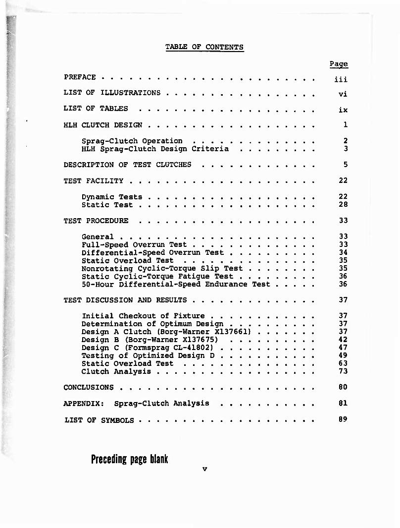
TABLE OF CONTENTS
Page
PREFACE iii
LIST OF ILLUSTRATIONS vi
LIST OF TABLES ix
HLH CLUTCH DESIGN 1
Sprag-Clutch Operation 2 HLH Sprag-Clutch Design Criteria 3
DESCRIPTION OF TEST CLUTCHES 5
TEST FACILITY 22
Dynamic Tests 22 Static Test 28
TEST PROCEDURE 33
General 33 Full-Speed Overrun Test 33 Differential-Speed Overrun Test 34 Static Overload Test 35 Nonrotating Cyclic-Torque Slip Test 35 Static Cyclic-Torque Fatigue Test 36 50-Hour Differential-Speed Endurance Test 36
TEST DISCUSSION AND RESULTS 37
Initial Checkout of Fixture 37 Determination of Optimum Design 37 Design A Clutch (Borg-Warner X137661) 37 Design B (Borg-Warner X137675) 42 Design C (Formsprag CL-41802) 47 Testing of Optimized Design D 49 Static Overload Test 63 Clutch Analysis 73
CONCLUSIONS 80
APPENDIX: Sprag-Clutch Analysis 81
LIST OF SYMBOLS 89
Preceding page blank
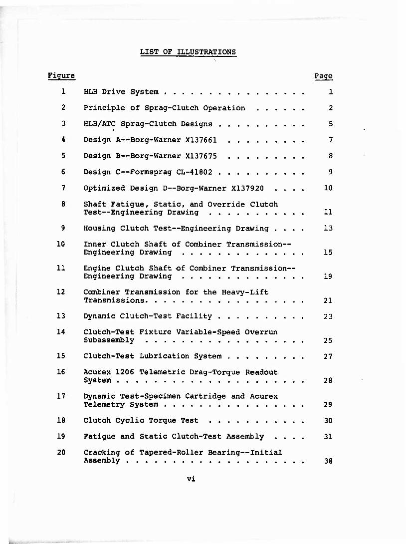
LIST OF ILLUSTRATIONS
Figure
1
2
3
4
5
6
7
8
9
10
11
12
13
14
15
16
17
18
19
20
Page
HLH Drive System 1
Principle of Sprag-Clutch Operation 2
HLH/ATC Sprag-Clutch Designs 5
Design A—Borg-Warner X137661 7
Design B—Borg-Warner X137675 8
Design C—Formsprag CL-41802 9
Optimized Design D—Borg-Warner X137920 .... 10
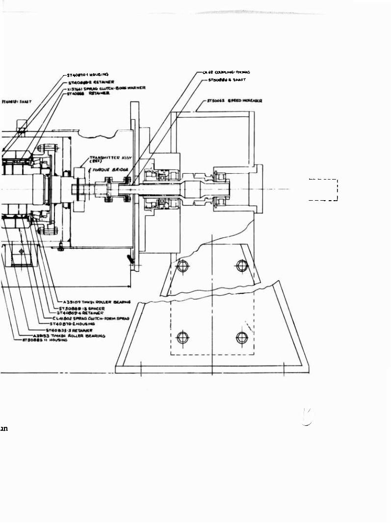
Shaft Fatigue, Static, and Override Clutch Test—Engineering Drawing 11
Housing Clutch Test—Engineering Drawing .... 13
Inner Clutch Shaft of Combiner Transmission— Engineering Drawing 15
Engine Clutch Shaft of Combiner Transmission— Engineering Drawing 19
Combiner Transmission for the Heavy-Lift Transmissions 21
Dynamic Clutch-Test Facility 2 3
Clutch-Test Fixture Variable-Speed Overrun Subassembly 25
Clutch-Test Lubrication System 27
Acurex 1206 Telemetric Drag-Torque Readout System 28
Dynamic Test-Specimen Cartridge and Acurex Telemetry System 29
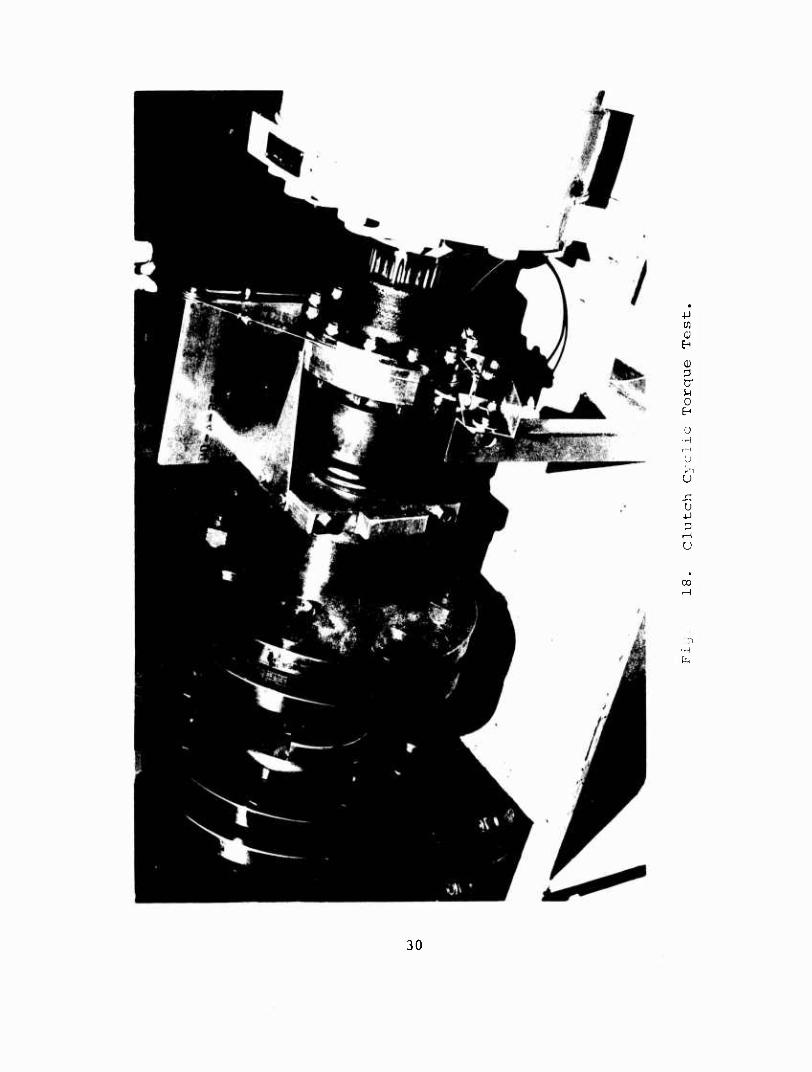
Clutch Cyclic Torque Test 30
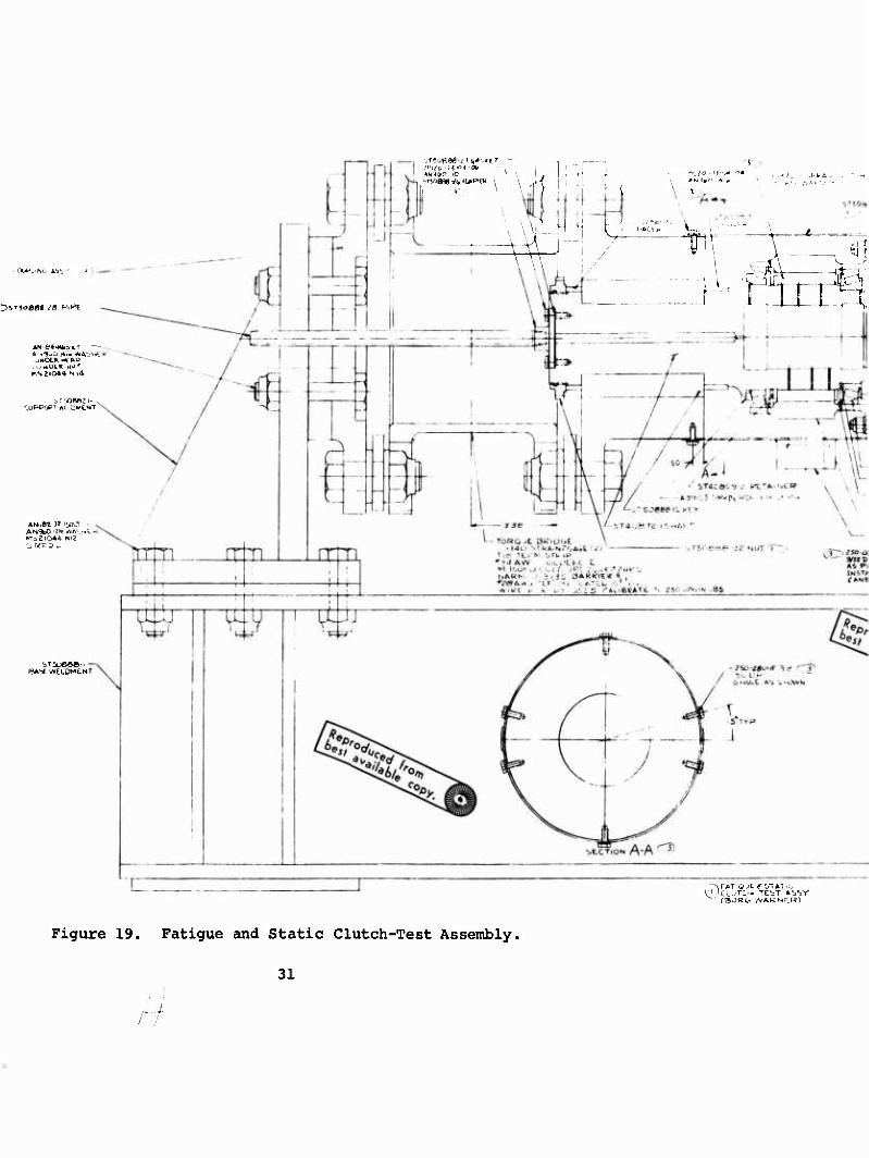
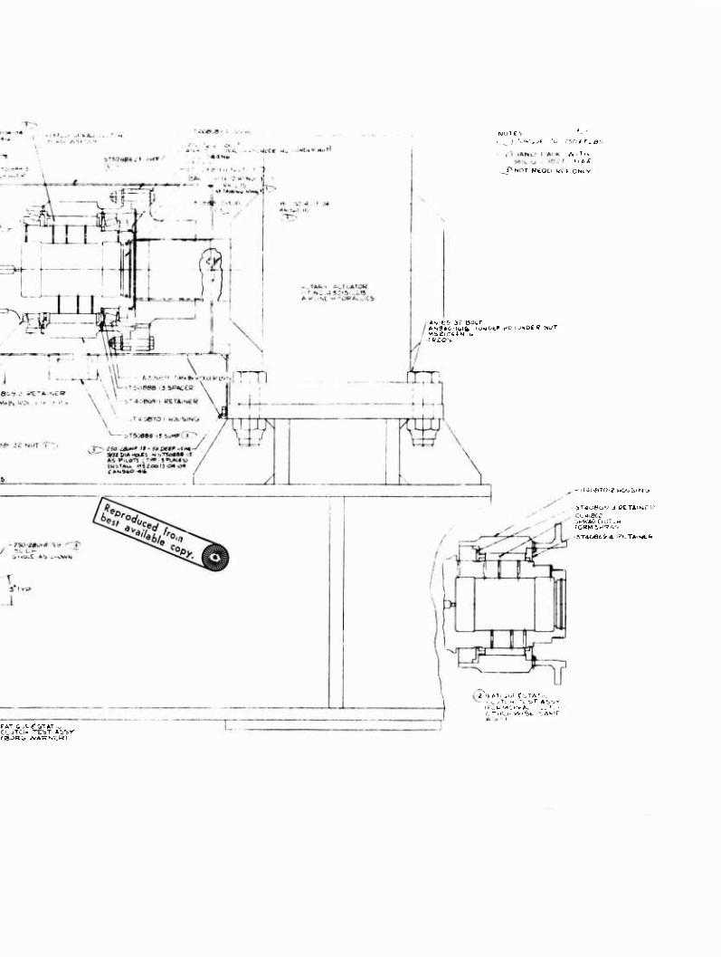
Fatigue and Static Clutch-Test Assembly .... 31
Cracking of Tapered-Roller Bearing—Initial Assembly 38
vi
Figure Page
21 Surface Damage of Tapered-Roller Bearing .... 39
22 Wear on Outside Diameter of Design A Drag Strips ' 40
23 Design A Components After 50-Percent Differential-Speed Overrun Test 41
24 Heat Rejection Versus Oil Flow at 100-Percent Overrunning 44
25 Drag Torque Versus Oil Flow at 100-Percent Overrunning 44
26 Heat Rejection Versus Differential Speed Overrunning 45
27 Drag Torque Versus Differential Speed 46
28 Design B Clutch Shaft Exhibiting 0.0016-Inch Wear on Inner Race After Disengagement Test . . 47
29 Design C Components After 75-Percent Differential-Speed Overrun Test 48
30 Design C Inner Race After Differential-Speed Test With Low Center-of-Gravity Offset Sprags . 48
31 Summary of Clutch-Evaluation Testing 50
32 Clutches and Inner-Race Shafts After Evaluation Testing 51
33 Design D Inner Drag Strip, Showing No Wear After 50-Hour Endurance Test 52
34 Design D Outer Drag Strip, Showing No Wear After 50-Hour Endurance Test 53
35 Map of Failures of Design A Energizing Ribbon After 50-Hour Endurance Testing 55
36 Map of Failures of Design D Energizing Ribbon After 50-Hour Endurance Testing 55
37 Design D Inner Race, Showing No Wear After 50-Hour Endurance Test 56
38 Results of Slip Test 56
vii
Figure Page
39 Results of the Nonrotating Cyclic-Torque Fatigue Test 57
40 Design A Cage Damage From Fatigue Testing .... 58
41 Clutch-Shaft Fatigue Damage 59
42 Clutch-Housing Fatigue Damage 60
43 Cracks on Outer Cage After Nonrotating Cyclic- Torque Fatigue Test—Assembly Similar to Design D 61
44 Cracks on Inner Cage After Nonrotating Cyclic- Torque Fatigue Test—Assembly Similar to Design D 62
45 Instrumentation for Sprag-Clutch Load-Sharing Static Test 65
46 Load-Sharing Measurement Scheme 67
47 Results of Load-Sharing Clutch Test—T-l Torque Bridge 69
48 Results of Load-Sharing Clutch Test—T-2 Torque Bridge 69
49 Design D Components After Static Overload Test 71
50 Inner-Race Contact Stress Versus Clutch Torque . 75
51 Outer-Race Hoop Stress Versus Clutch Torque ... 76
52 Inner-Race Strut Angle Versus Clutch Torque ... 77
53 Percentage of Cam Rise Versus Inner-Race Strut Angle 78
54 Sprag Geometry 81
Vlll

■'
LIST OF TABLES
Table Page
I Conditions for the Full-Speed Overrun Test ... 33
II Conditions for the Differential-Speed Overrun Test 34
III Summary of Optimization Testing 43
IV Load-Sharing Calibration—Row 1 Only 67
V Load-Sharing Calibration—Row 2 Only 68
VI Results of Load-Sharing Test 68
VII Housing Radial Deflection 70
VIII Summary of Load-Sharing Test Results 72
IX Clutch Geometry 74
X Comparison of Design D and Aircraft Clutch Parameters With Design Criteria 79
IX
HLH CLUTCH DESIGN
Reference 1 describes a program to advance the technology of overrunning sprag-clutch units to allow for reliable and effi- cient operation at speeds and loads conunensurate with advanced aircraft gas-turbine engines.
The test program described in Reference 2 applies the knowledge gained to develop an overrunning clutch capable of meeting the HLH design requirements. The design operating conditions for this program were 11,500 rpm and 3,795 ft-lb torque.
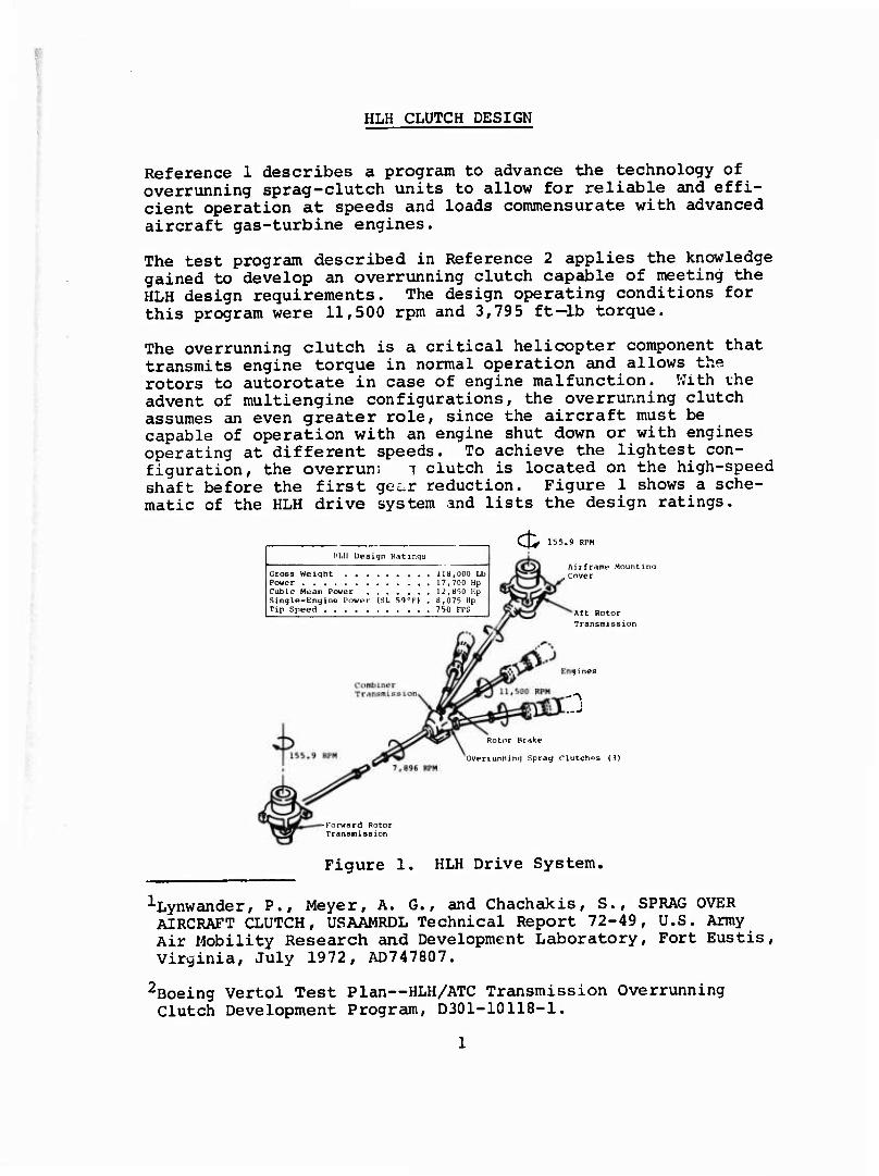
The overrunning clutch is a critical helicopter component that transmits engine torque in normal operation and allows the rotors to autorotate in case of engine malfunction. With the advent of multiengine configurations, the overrunning clutch assumes an even greater role, since the aircraft must be capable of operation with an engine shut down or with engines operating at different speeds. To achieve the lightest con- figuration, the overrun! T clutch is located on the high-speed shaft before the first gei-r reduction. Figure 1 shows a sche- matic of the HLH drive system and lists the design ratings.
CJ^ 155.9 RPM HLH Design Ratinya
Cross Weight 118,000 Lb Power 17,700 Up Cubic Mean Power U,Hr)0 Up Single-Engine Power (SL 59»F) , B,075 Hp Tip Speed 7 50 FPS
Airframe Mounting , cover
AEt Rotor Transmission
-'S
Rotor Brake
Overrunning Sprag Clutches (3)
-Forward Rotor Transmission
Figure 1. HLH Drive System,
^■Lynwander, P., Meyer, A. G., and Chachakis, S., SPRAG OVER AIRCRAFT CLUTCH, USAAMRDL Technical Report 72-49, U.S. Army Air Mobility Research and Development Laboratory, Fort Eustis, Virginia, July 1972, AD747807.
2Boeing Vertol Test Plan—HLH/ATC Transmission Overrunning Clutch Development Program, D301-10118-1.
SPRAG-CLUTCH OPERATION
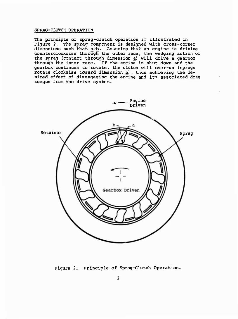
The principle of sprag-clutch operation ir illustrated in Figure 2. The sprag component is designed with cross-corner dimensions such that a>b. Assuming that an engine is driving counterclockwise through the outer race,- the wedging action of the sprag (contact through dimension a) will drive a gearbox through the inner race. If the engine is shut down and the gearbox continues to rotate, the clutch will overrun (sprags rotate clockwise toward dimension b) , thus achieving the de- sired effect of disengaging the engine and its associated drag torque from the drive system.
Engine Driven
Retainer Sprag
Figure 2. Principle of Sprag-Clutch Operation,
A spring is normally added to the clutch to ensure traction (energizing) during driving, and to maintain raceway contact during overrunning. To provide for equal load sharing (full phasing), a retainer is employed between the races to keep the sprags uniformly spaced. A centrifugal force produced by the mass and rotation of the sprags also acts to energize the clutch during the engine-drive mode. No centrifugal force acts on the sprags during the 100-percent overrunning mode because the tangential driving force component is greater at the inner race so slipping occurs initially at the inner race and the sprags remain stationary with the outer race.
An important feature of sprag-cam design is the compounding of radii of curvature, especially at the inner race. When the clutch changes from the load to overrun mode of operation (called the release position) , the radius of curvature at the inner race is greatly reduced, thus allowing the clutch to slip more easily into the overrun mode.
In addition to the conditions just described—drive and over- running—a third mode of operation, called differential speed, must be evaluated. In a multiengine application, if one engine is driving the gearbox, the clutches on the other engines are overrunning: the inner races are coupled to the gearbox and are rotating at speed of the first engine. If a second engine is started, it cannot transmit torque to the gearbox until it accelerates to the speed of the first engine. During this time, however, centrifugal force of the sprags acts to energize the clutch; this condition is much more severe on the wear life of the clutch than pure overrunning. This mode of operation could occur during preflight checkout of the aircraft or during flight if one engine is driving and the other is maintained at idle for quick response to any need for reserve power.
HLH SPRAG-CLUTCH DESIGN CRITERIA
• Single-engine torque is 3,795 ft-lb (100 percent) at 11,500 rpm. Engine rotation is clockwise looking forward.
• Sprag-clutch torque capacity must be 7,590 ft-lb (200 percent) minimum based on a contact stress of 450,000 psi.
• No permanent deformation or yield of shaft, springs, or cage may occur at 11,386 ft-lb (300 percent) based on a contact tact stress of 600,000 psi.
No structural failure,overturning, or slippage may occur at 17,078 ft-lb (450 percent).
Outer-race hoop stress may not exceed 71,200 psi (Re 36 hardness minimum) at a torque of 7,590 ft-lb (200 percent).
Combined radial deflection of inner shaft, outer shaft, sprag contacts, and sprag may not exceed 80 percent of sprag total cam rise for torque load of 7,590 ft «lb (200 percent) .
The clutch shall be capable of continuous operation at two- thirds differential overrun (outer race at 7,667 rpm and inner race at 11,500 rpm) . Both rotations are clockwise looking at input end of outer shaft.
Sprags must be made from N-50 steel or equivalent.
Cages must be fully machined and hardened.
Positive lubrication shall be provided to the clutch with oil dams to keep sprags submerged in oil during operation. Oil drains must be included in the outer shaft to prevent sludging. Total oil flow is not required to pass through adjacent clutch bearings.
Clutch-shaft material must be XBMN-7-223 (Vasco) carburized with no black oxide en clutch surface.
Surface finish must be as follows: inner and outer clutch- shaft diameters, 8 to 16 RHR; sprags, 4 to 8 RHR.
DESCRIPTION OF TEST CLUTCHES
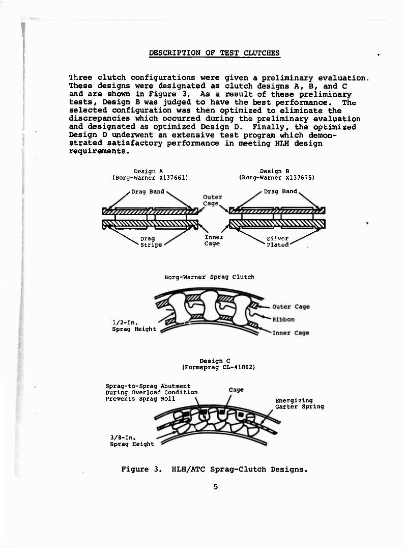
Three clutch configurations were given a preliminary evaluation. These designs were designated as clutch designs A, B, and C and are shown in Figure 3. As a result of these preliminary tests. Design B was judged to have the best performance. The selected configuration was then optimized to eliminate the discrepancies which occurred during the preliminary evaluation and designated as optimized Design D. Finally, the optimized Design D underwent an extensive test program which demon- strated satisfactory performance in meeting HLH design requirements.
Design A (Borg-Warner X137661)
•Drag Band
Design B (Borg-Warner X137675)
Drag Band,
^sssssss^ss^^^^ Drag Strips
, »N^^W^CCVV^C^ Inner Cage
Silver Plated"
Borg-Warner Sprag Clutch
1/2-In. Sprag Height
Design C (Formsprag CL-41802)
Sprag-to-Sprag Abutment During Overload Condition Prevents Sprag Roll
3/8-In. Sprag Height
Cage
Energizing Garter Spring
Figure 3. HLH/ATC Sprag-Clutch Designs.
5
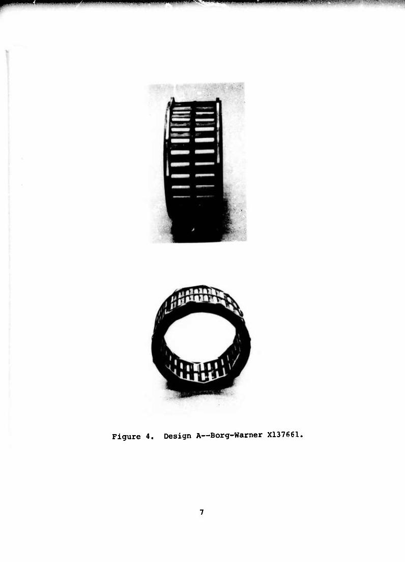
Design A, Borg-Warner X137661, is a two-row sprag-clutch assembly with tandem inner and outer cages incorporating two inner and two outer drag strips and a central energizing ribbon. Design A is shown in Figure 4.
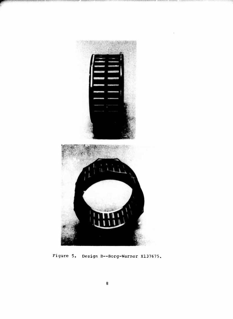
Design B, Borg-Warner X137675, is a two-row sprag-clutch assembly with a tandem inner and outer cage incorporating two outer drag strips but no inner drag strip. Silver-plated lands on the inner cage pilot closely to the inner shaft and use viscous drag to actuate the cage. Design B is shown in Figure 5.
The function of the drag strips in all cases is to create frictional drag between the sprag assembly and the adjacent inner and/or outer races, thereby aiding in the assembly cage actuation.
Design C, Formsprag CL-41802, consists of two single-row sprag- clutch assemblies, each having a cage and two garter springs to locate and actuate the sprags. The sprags have interlock- ing surfaces which prevent rollover when an overload condition occurs. Figure 6 shows Design C.
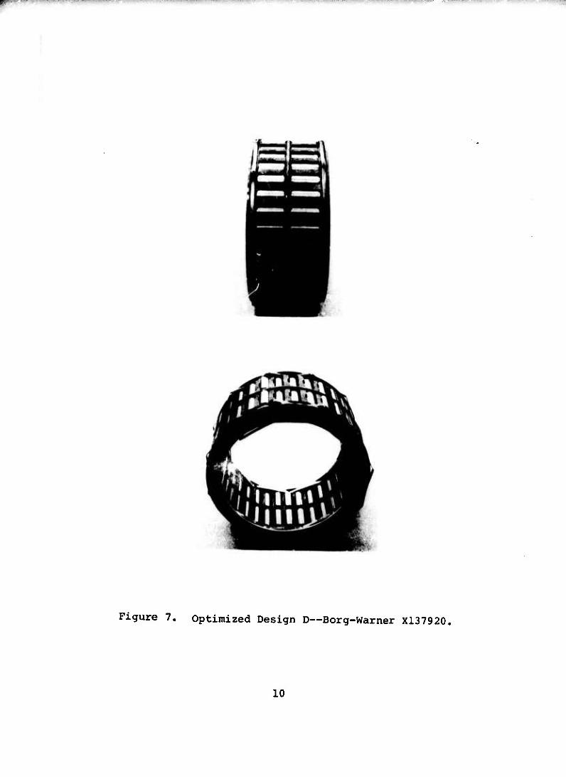
Optimized Design D, Borg-Warner X137920, is similar uo Design A in appearance and Design B in configuration except for opti- mization to eliminate minor discrepancies which occurred during the preliminary evaluation. The design consists of a two-row sprag-clutch assembly with a tandem inner and outer cage incorporating two inner and two outer drag strips. Silver-plated lands on the inner cage pilot closely to the inner shaft. The race-contact surface of the outer drag strips were increased to minimize wear. Figure 7 shows the Design D clutch tested.
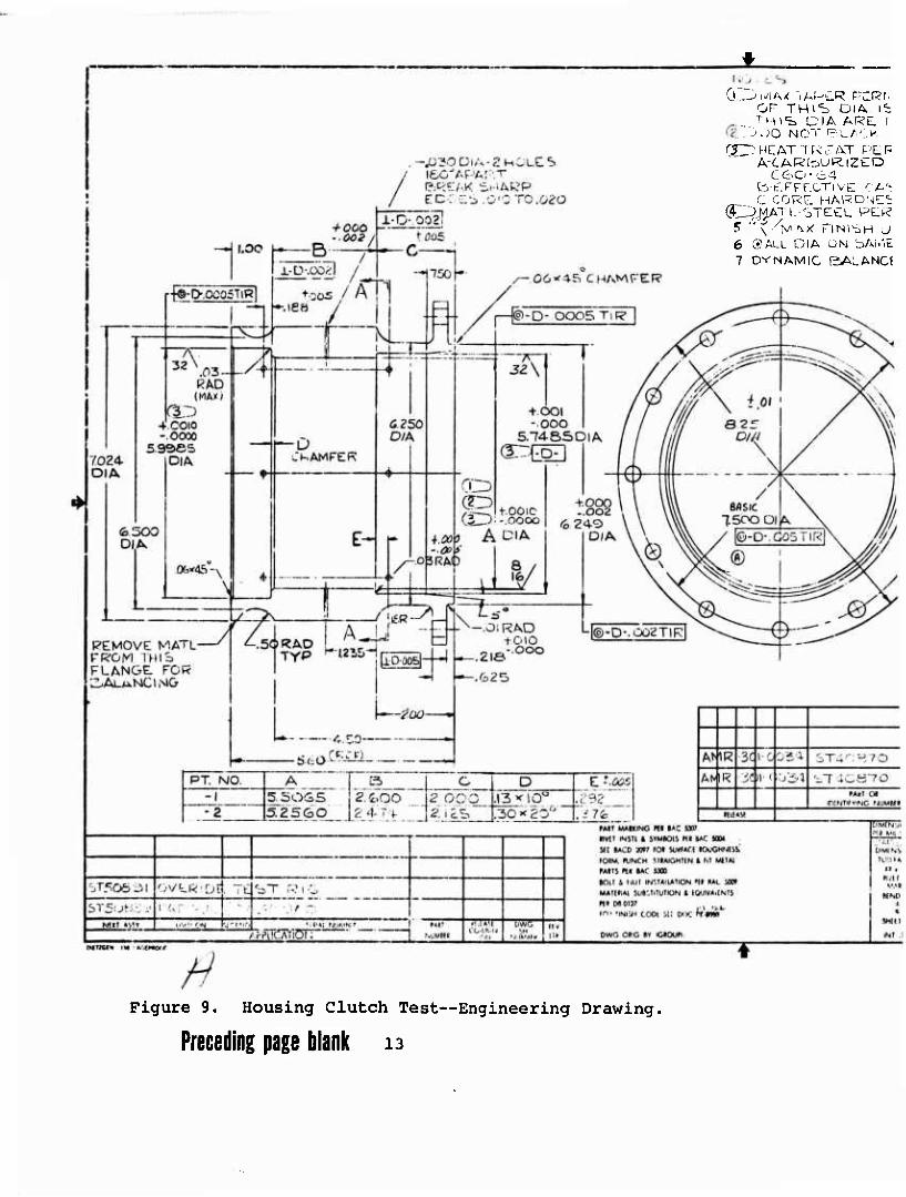
Lubrication to the clutch designs tested was provided centrif- ugally via holes drilled through the inner shaft (race) , shown in Figure 8. Figure 9 shows the outer test housing within which the test clutch was mounted.
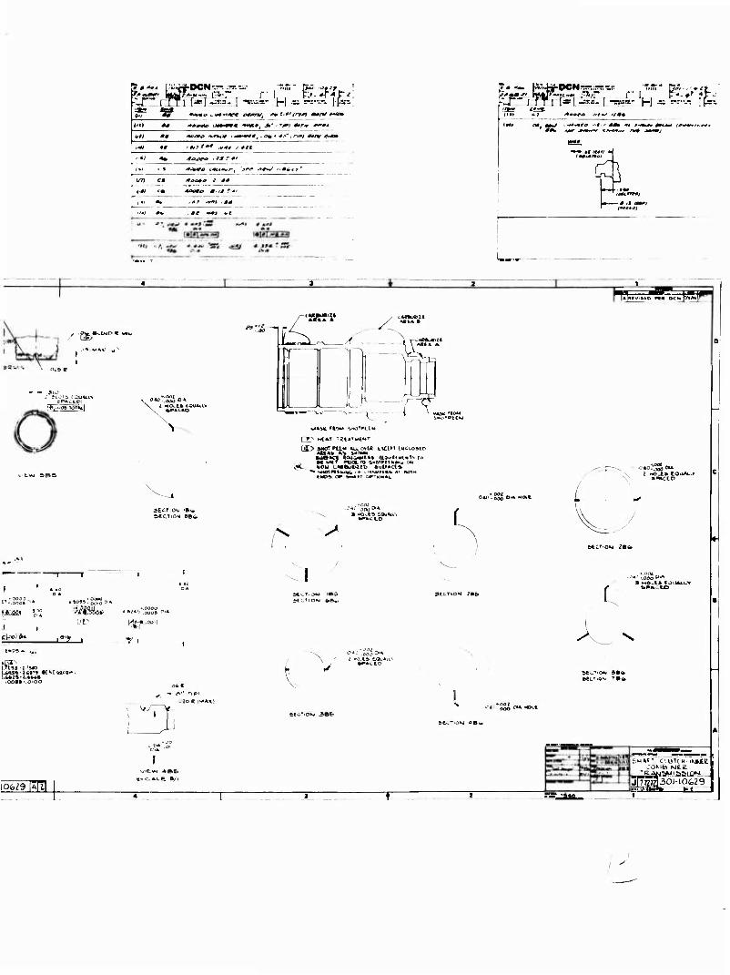
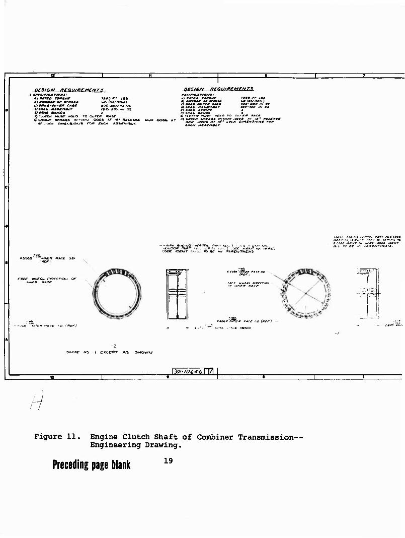
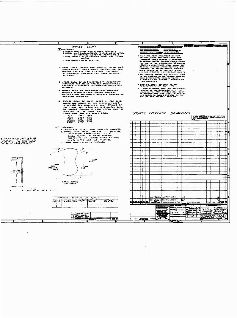
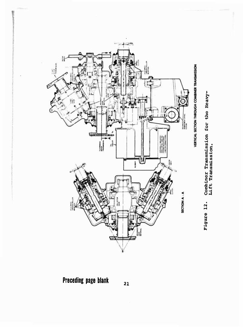
Figure 10 shows the final HLH/ATC sprag-clutch design, part 301-10629, and Figure 11 shows the final HLH/ATC inner clutch- shaft design, Boeing part 301-10646, resulting from this pro- gram for incorporation into the HLH/ATC combiner transmission. These final HLH/ATC parts are identical to the optimum Design D tested. Figure 12, an excerpt from Boeing drawing 301-10600, the combiner-transmission assembly, is also included to show the typical arrangement of the sprag clutch in the HLH transmission.
mmmmmmmm ^mmmmm mm^^mmmm mt-wmmmmim^Mi.vjtfn^ vw.immmum "■
Figure 4, Design A—Borg-Warner X137661,
.p«iiiw<iaVi.i,<jI.>ijH "tntm'^^'^' -.-■--......w.-,-.J-..i.^....w..»-^^-. -» ' MI" ■« nyijipip MB*!"!1"
'*.
Figure 5. Design B~Borg-Warner X137675.

^n»T....«r,«.v-T-,TT.rfr"'n-.-w;--... ■ .-^..^ , , , <I.M..^..WIIW*.I
Figure 6. Design C—Formsprag CL-41802.
"■■'■•"■■■■-■""^ ijuiiunm«™"!»» " ' " i' '^"v•■•«>., ■■■—"""•■— . i i itiwjiiiuiP ,V»IIPII»IIIIW«HW""-.^" T!» ^i.nii.. <>jiu>iiKm
Figure 7. Optimized Design D—Borg-Warner X137920.
10

M r.TT «, TC* '.'^.^M.V/. TAPCR DC
\ OF TM^S UlA ': ^VA . D!A /-.t',?l IMOT
\ (^ .3 DO INCTi ii_ACi \ '3 I.; hiCAT TP.CAT ,"->?.
1 DE !O• lOi^i" ,., ! ~ i AC fiRBCRlZEC
„ ^J3.M>/ // erErreoTivE ^ / / / GRlNOlKCr .
/.pa C-CORE HARC / ^ (47D MAT L - S r££L <
' ^_ -'■'5k*- 7 ALL DIA LCNCItJ
i>-,n -;• ti"/. JC»" '-'il^V V'"'1 fifN /' ^ i l>IA. .M.Jn/Ü-■. '- M-- "--i ii •;--'—• K-»--l '-: ...i-L'.-OU- -.two
?2 \
I E
f I
4
I.OD U- i
4 500
' f\/Kf.
-.OSl'AO
i i i1. iTIfi ■' 1
■u^r Ifli
I / f I
1 2.&*l DlA
505
4 0 ?it 7 .
J'-' 'M f; 1 . x/.'. i
D'A-
AT
SOM + 010 Q3ZSJ-—
-« ^^ \ i
— a^s- I.J i-A/.O.J6-
14.',"5
(^ 3-ij b - -. -■)
tLK \
,r L Ä'ÖOCb |
1.675 LW. [-.f
B.C. Bfl5!C Vv/ ^\_ X\ /^4 -' "^ coo T
.95t
^-3.7 9S'^ 01/1
V-.C/6E DIA (BREAK bHARP -IIG i4-'MOi.Ew-,Ufec V3i*. MOl...
... v\ /\\J} li ! 4- I
A AMP^ii' ■•)u.
U-"' i I.CO0
to*: ^ ri.;r ■N'ji/i.j.'',>N PI* '..-': *av V.'T-viM V.p'T'-.ul/JN « [7.1 *l M'-
r—n — -- —
—
—
-- —1 -4037a-, ■ i 1/ *.
'■-I'M-"1»!
"'"7 .;,",' — ---;- ;--^-v-,.lr7jyTf,;-■ -■ ^ 7"""~', .„'■'^:9f.' .LJ32i'lLs.'H-iüj£l G50.
toiiw trir IM ,,c:
HMJ '«ei.
Figure 8. Shaft Fatigue, Static, and Override Clutch Test- Engineering Drawing.
11

,
MOTtS (j£2wr-y. TAPCR >-'L.RvnTTF.i; -V.M.TH
OF Tw\S DlA 'z-.ooo?. '-i-'--- v , i Hi's OlA AU?El UOT C'Ulkr/MTlF---
Cii^^'OO INO"l 'iii-ACl' O^'i^r TH*^ r.:A \ '3 ') HEAT TW;t.W pf.'.R BCONCJ OUC J\'<'-1\'7
1 ftrCfcRBuKtZCD CAbF. HARDNESS POCKWEwV, C«C-64
EfELFFCCTlVE CASE DEPTH AF'TCR / GRtNDlHCr .CTTOV.'O
IT:
__.J!hV!VONi
r .v J -^ .i v., .:."",'"i \!L.
lit-'i'jTTi ?..o c« i j j.i i wA -in -.m t.go << TO ' .3 Ji
'!■.:.•, CK i«V !& ■M
±M T
"s>^_l_-'/ /i200 _ C-CORE hARÖNCb'i ftOCKWc1'- rl^-4£'
^. I •^'V 6 A/MA.* RHiSH UKUES5 NpTSIO
ü:; ^v/^"" —* " ^S , .-jnoL^ 7 ALL DlA tCNCCuTRlC 'vMltH DIOT'^ UNLfS^s ISO i EC.
•^ ^ 11,1 --.t^-'"^ £ r1'J r ;: ^.V/A .,.. nu\ i If/''// x. \v ■ L^ ■ ^'T^ir"i ^L..i4i...i_! ^..^4, - [—- --^i ,— , j{l/T]i 4 'h~£]--'--~t |TY' 4
:_ N i.)
, I I t _•
r—Hv-"->'* Ji-C AUv-'^iui.^:::.-.^
® -3« *.5 PP
j^-^IO Dl/l|
~(TY(' 4 PUS)
Cy'<S.'f/
ij KC-^I:'^ (HF \
-U-AOQ05I
5.8» V-
to 5 00
-,952 1 01
-.c-üö 3.0t&-l2Nb 3A
-3.375 Oifl ß (C
®
-3.798 '0 OIÄ
\-.002DtA(BREAK 'bWA.RP rIL'-G
"^ AMR
■ .■,i . ■ • '
;.■ n ii j .••.",•;•■! n; ■...: .«J
»M "-J'JCH '..'>>•..I-UN /. 'IT ''I'M
us > ■ i-; J'-"- 1'r s Iwl 'iSi/l;*! '.IN 'I' '..•'; ?J<.' itt«*l ■..»'."VuliQN s I - i.n'Ni'.
i< n .;>i L-'OI .'■ '.'O . D'.l.v
..T4037i • ! TT;—rrvr-
►*8T 0£ 'Off'Tltvif.i '. S.-UM6H M ^Ct'fflON
2£.-.,;,'v U" C
M/.:'.(r*i « SKCHiC^TtOM
"*/'''r,ONNC*.' OU*.*NC'* .a«- USi Üf .'.'AitViAL
Ol^,•^J■^.N■ A.^ 'M INC (MJ.-. ,' MOvi^S
XAiU'-rx: i'i ,ics , .• i -
»vtt ^ p.jii !DG: .x'.i I >.■., tG I ij > x I
ib >AC'li I 1 01 ... ..-. !. C- I * 03 Gfi t» > l.«fAIt>
'.T WIM '."••■II "•'. !■ - —
tv—
i; II.: iA „ t
fHt *3»4:J,fcJr-l»'Wj5? COMPANY VJRtO' Dr'ISi'JN PHil ADllfHIA.F*
'M, l.wn:. MO(.-
1 './?'JL. ■0872
itch Test—
0.---M^IA/ "IAPL-R PCRt. OP THl'b DIA I?: THl«» DIA ARE. f
..'UO NOT P-.LACK (TT^ HC AT T R u'AT PL P
A-CARfeURlzeO ceo-64
B-£FFr.CTiVE CA6: C-CORE. HARDNE^:
(S^JJ^AT L-STECL P£R " "\ ^M ^x1 FINISH J 6 ®ALL DIA 0^4 bAi.'it 7 DVNAMIC BALANCf
Figure 9. Housing Clutch Test—Engineering Drawing.
Preceding page blank 13

■I
MAM r ER
(l^J^M. TAPt-R PCRr.'.,TTZD G.""":' LenGTH OP TH»"^ DIA. IS.OOO? STk'PSON
_ THl's DIA ARE. NOT PERMlTTäTD u? 3L)0 NOTI^-.LACK' O.A'IOE THCJS OiA. ^53r,MCÄT"rRlrAT PER oOCiNG UOCJMEINI O2l0-i:3 i
A-CARtoURlZED CASE HARONtSS ROCKWEUU. C60-64
B-EFFF.CTivE CA^E DEPTH AFTER GRINDING 070 llO ___C-C0RE HARDNESS ROCKWELL C3&-42 (JlJj^ATL-STELL PER liOEING SPEC XBMS 7-2?3
5 'X./M'i* FlN\SH UNLESS NOTLD 6 ®ALL DlA ON SAME Q.OOSTIR
7 DVNAMIC EALANCE TO .Ol IN CZ
/ REMOVE MATU FROM THIS FLANGE FOR BALANCING
HJJTL-J— _. REVISIONS
OCiCB'PtlON
jCtffflv/iCQ returwci ".' gmr orfcu J/'/TJ| H ■ ■Ly' ( DAttl»>MOVtD
I25DIA 6HOLES EQJALLV SPACED vv: iTt .11-1 .OlO 2 PLACES
-+■000,5" ..0<7Ou
37^0 DIA THRU 2 MOLEIS EOUA'-Lr
SPACED oos SIS® SECTION A-A
taw AMR
AMR
3C I- C
i«ii(
•tltASt
.T- ■ilO
;T-4CÖTO »■I ot
IPtNT'F^'NG HUMflft
MOUSl NG
■'SING NOMfNClATUH 01 DtSCgMION
3.50C 'jiA ..-^ /;o:
■^ ., - w- ^ . I '-\ ■
M*-»»l*i A '^fCinrAt, ;w
Mil MAKING ffl IAC S307 ■veT iNsn t STMiois HI HAC SOOA
SIE lACD »97 FOI SUtHC.l lOUGHMfiS.
tO»M. HJNCM, 5IIAIGHTSN 1 HI MIIAl Mrs nil «Ac uoo
tOO S nul IM'.tAiiATION nt ML MO» MAIIIIAl UHOTlTUTION 1 IOUIVAIENTS
HI M0I37 .j »r>' 'INI>I cooi ii: cxx: ^«i»
DWO one «r ciou«
'J\MH.,O> 41NG » TCI tiAnr;'i'i5
DIMI NSIONJ Air IN INCH! "i TC-HSANCfS ANOlfS ft
M.'>.-..NS »M «ND MOii: '
x 01 (»> m t u ft 03 CN J9 » C'tATEl
SHEt) MtiAl COfiNlfi EAON
INT i« 1; (11 a
1ISTOF MAffSIAl
-14. a)
MAIL t noctsl
' *' ** Sliun /
; m
THF & £f/TS/tfdr COMPANY VFdlOl DIVISION FMIl AOtlPMIA.PA
I lü'JSiNC» M\ I 1 /
Cl DTCH TEST
IM '?.,'?. 40876^
awing.

£(* I**»« rtftin^j»'«*» J^iiOCN«
»/ •it,*/*-*
ItM^ I rrri=u™. i -==.-- H -- -:■■--- ii--:
'£&**** *ftj .**i?Zifi**~
tn Mt
« ■■-s- ■.. —=-: Ml
«r« ***** rw jMtfWWM^M» *«?*« j*»r^>*M«Ai «•
CODE OCMT MO it«^
^ \
l I
•-000 Ä ^ ^.
-■ . 91 J"
VMS x^m»
I IO.O» —
a.24>
>t _1
ö'»«3- •.[-
VIEW ioe.6 »CAL» ^(
i W MM. ® '
I ..w 4.äJ ifiaaa*
o * I'C'l
-- -M /■££ i1-«.«. 4 --
— — ^'a.'.ooo
•■ftt &OtiW& fttOCti-S bPCClFiw-MlOKI »*C »41«
• l.tPT A^ MOTKD
rv- --,
-tl tt-
.12 a
A« MOTIO;
4.Tt 4.4* Ifl*"*» """'■,
JWliMD'* -r« '.n- vitvy
t* ffis^ «
K M4*.0I U -- --. I .«»J" B.TCH DA I.fc939-J 49^9 •!*' •■i*B'»l *C>*^ ►-i^K-OI-^ ^ , i". •'«Bf .L4II - | R0OT eAOiUft .OOB»-.OiOO
T '
1.16 I» 3
5.03 i.0i lo.toatai»)
-r
SatCTtOM AC-
|/* Brooi
1301-10^9 lÄfi]
Figure 10. Inner Clutch Shaft of Combiner Transmission- Engineering Drawing (Sheet 1 of 2) ,
Preceding page blank 15
!« # ~. I w J*DCN-.r-. :rr. Z..: 'Tim " fiw- ^# J»
a- H •- ------ It-"- AT ••»»•u , .»♦'-'■v« ecrnf, ft-*" iryn mmrV ***>*
Ms ******> mi*09* ■**** Jti' ■ *Tß*i s»rv **•*
*OMO rvm* t m*0t*t. &* • *•■''. '>" ««/v f*<*u
• MT 4m 1 ^jt** *f*M / *tt
• *J ** 4CHJ*O . *s r t»
(*t • s ****<> im.'.»*'-, 'see ■****/ '**,.,• U7} C« *i»c*t» i *&
*£**a m- 'S i.
.mt •*•* *e
?*— p..W.OCNr.m;rT.-^ TAT BÄ-/'-*«»
•JT. l IT l J«! 5*3- 1 -==- H •- s-s'V-. !fr-. A*0*0 *'tmS IfM*
9
f
l^oös ToWi
,.EW ses>
I I :'T-
-i^y
:.n95 -I ': I.TlSS -t.tMO
\ ; Mcxtt tauAkky
- w,
o6 e - JO" .^P)
z- c«nu«tzt. / AKfc* *
IF
. t^A^e. ft/1
*/_ ■->
\ ASIA
rT MAS«. 'tQM SnOT'tt.W
GO *HO' PtLM AU. OvU ElC^I tMLLOSlP AJLIAV AS SNCMN ftuv>ce ioociNMt** uauiecuiNT.s to
. ftt Mt.T ^KX. ID SHOTref MiMu Oh «1 UOU CABCUKiItt) SoitActS
/X A
i SICTIOM 3ft6
3tcTiO*i ;•£•
N
■o*0-35o »• V smcto
fctCT.QM Z%(m
;,
Aftc-.OKJ 40^
COW© W£Ä
-LA SiiiS§j§^ I A FA
t tu. oumwm » « rmmn\ atm** m m mumm m UCM OHO mmm ao IM I«UM onoMnc Mono
r~y>THS MffT is A CLASS A (MVCM. «MT 4ND RfOuMS AL4. TESTS AND «COM» VfOUlD f*€mrm m mm MOCESS SHCKMIOH WS M OO FAnuTiai »MLL K m accomm WTM M OMÖ
4 «UMMMAOMOSumCE «OUGHNCSS '^CKCCPT AS MO TCO
|""g>—« ON M.« run« v nma im FILUTS
6 «iATM A/AAjtH P09TiON OF VLiNC TtETH WO MLCS OPnONM. UH-ESS SfVCTKD
l 3r>*«*r nunoNT re oaoKO AMAI FE* KXMC PNOCCSC
DOCuMtNT DZiO'iOSAI
• amminocm mtat» c ovicTM CAX ocrm ATTE*
0 OH HMOCU MOCRMLk C
Ha gg jjo-aa jg J^-
t (NM AT tStf 1 Iff' R* «X* HOURS APTCR FMAL OMO r com. imoos «HATIOH ts NOT TO ENCEEO foun ROCKVCLL C rauTt rai A MWT
HUMtlt m IH.L «AT LOT
Ö MCAK ALL 9HAIIPEMES MOT VEWCO TO A MAO'US OR CHAMFER OF 010 TO 0?0 VISUM. MSKCTIONOF TMB OI»t.«0N IS SATIWACTQirr
lO MTAL CKHHtSKCTlOH PCMtOClMG MIOCeSS SKCIFCATION »AC 5434 PMOII TO •<ITFCCMN&
«TC WTiai ««CTO» FfNKXMiFWnsSSnCIFCATlON MC »424 CLASS A C8lT>CAL IxCUM *» W)TtO
|FER flOEINC MOCCSS VCdFCATION SAC i/JO AFTCfl R To HOMioe ivaMBamBaHVi cxarr AS NOTID
A «OT SUE iO ■ UK «CMT OCS'OiZ AZ c otMOum. ioo>.
iS ttWJTV aMTMOL ««MEOM ACCONOANCE «TH BEWS RMOCESS SKCFUMM Mt Mt»
(7*> Ali. TMCAfit n» VCOFCATION WL'S-Mrf A« FEDEML HAMOKXW H-It
ift aKMICMAL LiHTS «W SURFACE ROuCMICSS DCSKWAHONS APPLT AUBSUMFACE TREATMENTS AMVt)H PLATiNC.UNUSS (JTMfRWlSI NOItO
nfa> 5i3l-IOfc29l SMAfTTöfl DvToAutCALLY •ÄtAHCEO -Q
A«t»Ä A» uauiecD.
U£> STtPS OW TWS D»* **l WOT »(.BMiTTeb-
rS^> 'OZ &K*Nt ^SPECliOU iM . t^ Of äAäE& USE
AMD CHLC«. kiDLU, »£AC), A^D PftOFlLX OtV'ATiOMt cw e.ACH **Kr.
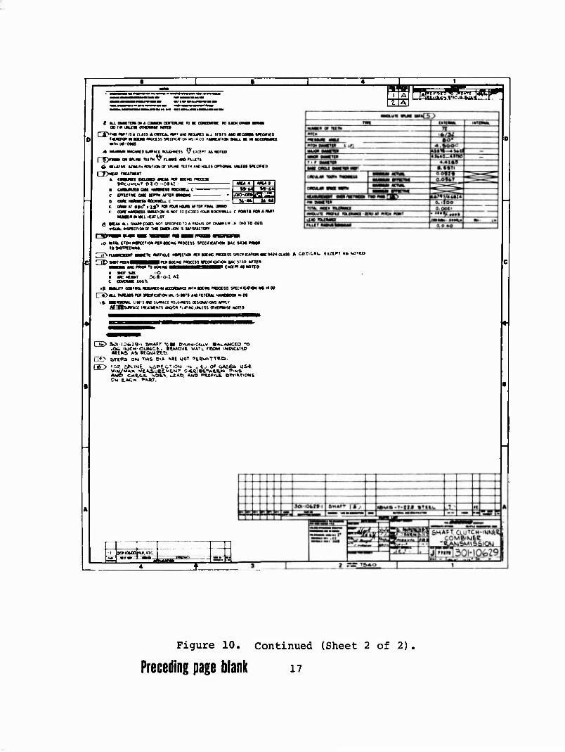
Figure 10. Continued (Sheet 2 of 2)
Preceding page blank i?
D£5tQA/ *£QU/*CM£Atr*
A) it Ar so TW04IU* lamorr to*
C)0***-O4*r** CA4£ »OO-MOO tkj Ot
Uem**-ASSfJiSAr /SO-JSC '^. oz ä)0*A9 m^MOi * S) CLUTCH **Lf*T MQLO TO OUTC* «*.CC QtQIOU^ S^MA^S WT-H'KJ QOOS Ar *»• ^CLCAAC
'9* t-.C« OMVW&'OVS ''Of CAM ASSCÄ-HiStv
QiSiMßL **ou'*£HeNrs •»»mo rr Am*. 4,9 !»*/*0w) tme-too //v o> 4me-fso /At oz
AKJO OOCK» AT
mmctrtcArfOtts • 4) if AT to roamv* D MVMmS* «* smA*s c) m**m ovr** c*mm
«) «XM« sr/r/^s m pi o*Am m*MOs i ♦> ctvrtßt MUST HOi.D re our** itAcm M) **Ot*m ****** WtT*/* .OCOa AT /*• ***£**£
AAlß OOOm AT /S' LOCK O/Zfä/VS/OA/S FO* t*CH AS-MCAfm*.*
- AiA^<t /SQCHJQ Vgr*TCM. nhfiT K/:., i ■ .i.t- »'CUT Avs. VCAJOO« f*l>Ar ' J-i . LP'&L 'l>, t -JCC *0£K/T Kf~ «f«£r.
COCC fOCUT Mo O. TO BC "^J PAROVTHCbtS.
MA»* aoe<H'i
At-i. ro me .
r&> IKJHCR OM.CC 0.0-
S£*'CL PA*r Nu $ toot .C* PAftr Mb., 3t*$*i, Mk. .-* *£**. coot loeftr f.- PA ffeNTHCSiS.
race WHCCL. cyRCCTioKj or
I
Jfa£ KjTCft niCC t.O. tRCF)
^-S-
- 1.470 AH/.
5Ä.MC AS ) CXCrPT A^ SHOWkJ
|3<?/-/^646r[7l 1
Figure 11. Engine Clutch Shaft of Combiner Transmission- Engineering Drawing.
Preceding page blank 19
7 1 » ♦ » ^ 1 ,__,, ' WOT£S co/v'r -
* «AM4i- *r.K> »rtMt, HA0S*M*e rff 0k «/•*« -«» 0*C4*m
^tf* */*# /.v T«# Am,cjkr,**(») ißtcmm D MMmtOM. A 3vm*rirt/Tf ,r£s* auMtt M»T 7 c*>«« jr^/>.j a^/vtf5 -*/Vtf »'aaosv r& am 100% ** «£« wrmtw mmto* rmar,** M*O
W%**sC**r w*r**A,r ********* *** 1^^*Z.&t?'&*Z.*IS%'- aew p*cc*ss SW,C*T/OA, a^c ***» Av.Ar/wlrsrm*,* coSttio, *T <*<,**, s»cce**r*aA-c£ <:*/r£/*/* ■/vo st/titcAT-sesv-s
ms»n nmeftMtwAt. mem»v****M*rM CCMMOM TP Ad* **J¥OC»S A***A* O*
m. CA»t» SMAH ms /MX Pt.uo»*ac**r mm*tmr*M*T ™'* ********, /Atsrmcraa mc* »omtM* P*OC*SS aßmct*ie*TtON ^ %iimmtm* *—** COVAV*** r» >«* »AC 3*j;m. ACctrrAttet. CAtTe»tA~/*o /*/0*cATie\ mtovi******r3 w 090,- loeer-t.
S. C-Urct* AS*M**mt.r MMAt.4. »M tMOIViOVAu.* _
a s**Ams aMAti mm *PO% rt.if*tsca*T *f*4*mrtc *«««#o 0* CCMTAWAIUO WTH THE
PA»T,c4.m wrmcrmo mm* aom/** mcmam Tl^mZrJ^couf^SSSr1*^*!&%,
■*0'CA-r*o*f Aiiovtmo. »AttAtt *•** BAC *aöT rvmm ma.
/A $*mm*a JMAU. am coto* cooao IN "to, »t-um. ifnow A*» a*mm** ay rna »tANurjicruRtti rp otAfcrm zt*m imet/fA/sa. cwt.* sf*A6S or '*e cOLOt* Ana PtmMtTTMD m A ct.vrc* ASSY.
THf ectomce PORTION or t*cn 3P*A$ MUST ee C
coior coot *— si» x«w~ ttLo~ SOURCE COA/TROL Df?AW/N6
ztt ;n;-«" iigasiiaf*«««««! ttuow sooa ■ .seea ■"■
- «MV/V • aaos - aooa
e. 3PnAr*^ M so srrri-, NAROCKGD TO «<. &» <*s. MiCAC&ccW c»**^/iwAr<oAj 'roc-) SMALL 1CVCAL K/O VtSUAL. «C^AINJCD
- act.*i-.-£*-CL. PS*T *tm$ COO*
rc ae "V r*Re*r*esis.
<•
■ -^- at,,- ) /
i1 roeet ' \ 1
sooa \ toao§ (ßti.*Aa* \ sits
—) ^-^^^--.l 1
■•
\ -J ! see S*V*Ai
1C£ *£'.<-
A
• - - z.+rS 'AHUH. $*>*
JU/ /«»<*■■ .LUTCH Ai^y 2> vf
5 E K E 5 E ioifom-t UUTCH MtSS* s ZE — ksJ ! %ijfAt,*tm *Af**,AoeAmaa vsüsr us? fci-
* I zzzt^zr = ■^Mmr^r« —:£■—s=s—
—^a' T—d^zt! ±; 3te%^ 10. eM6i*e SH*rT A
i yJi/OLOt "'"/tn. ■W^T -/ UMtft w%rc l^V IS\£.A-£ L«^1^"" ! __ .^m ^^-^»NJ SKÄfCfcS^-^eT" j
» * 3 »' - ' J *"- -Äfff.-ST?—* ' 1 "
(0
X
Q)
U O
g O
•r< 0) t «1 C
(0 CD
ä I EH to
U § (U M
•giJ 83
Preceding page blank 21
TEST FACILITY
DYNAMIC TESTS
Test Stand
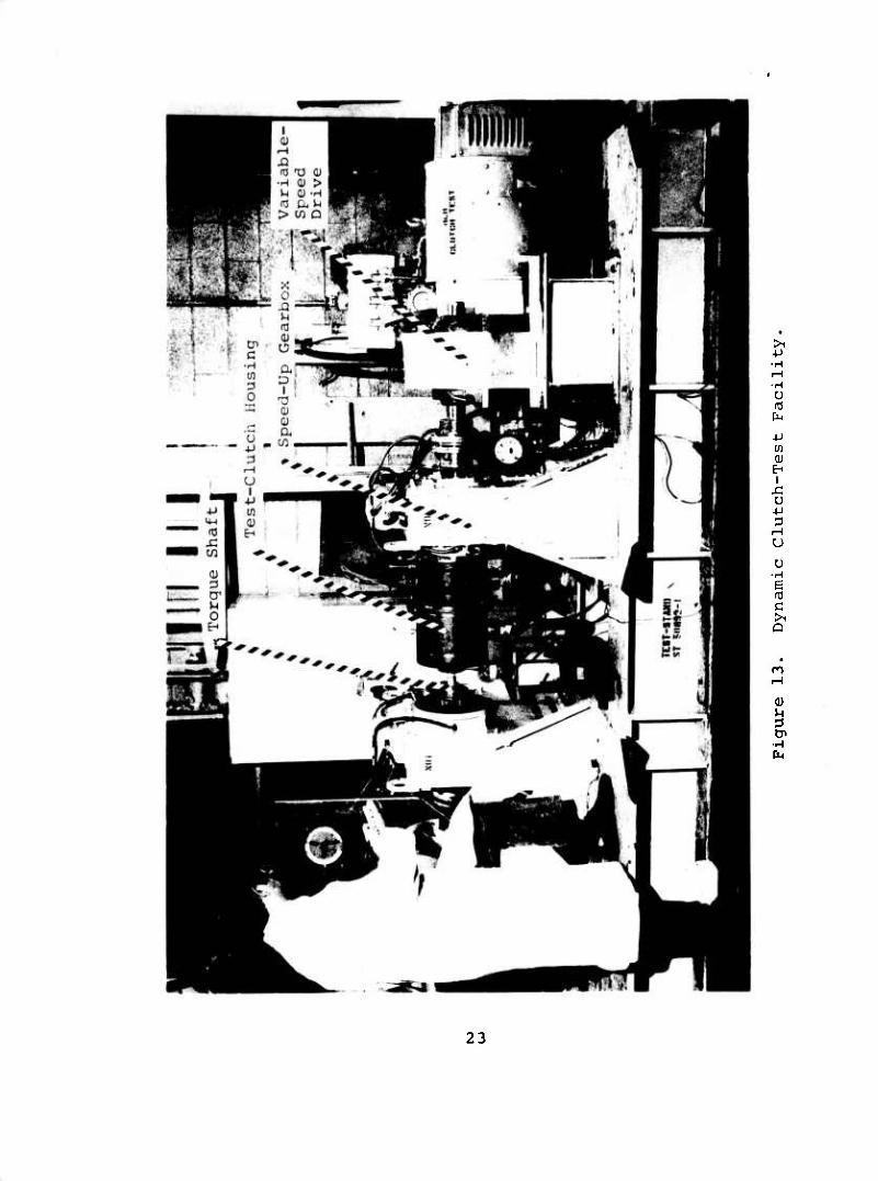
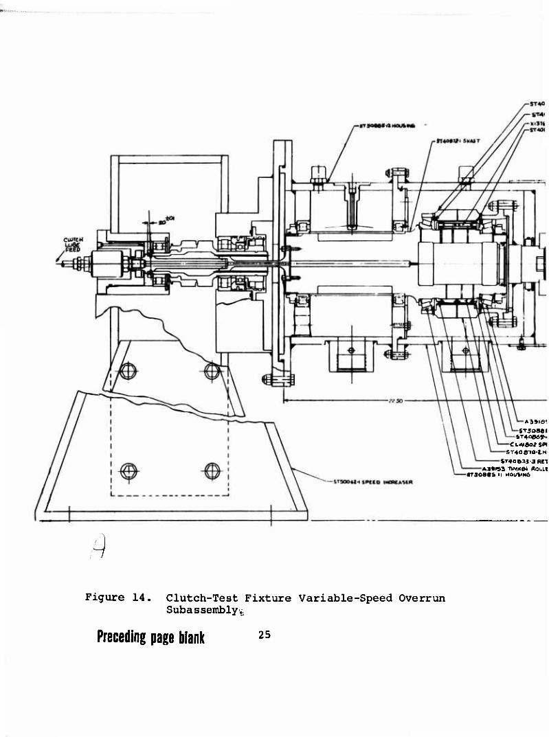
The test stand shown in Figures 13 and 14 consisted of two independently controlled speed increasers mounted on a solid weldment. The output shafts of the speed increasers were aligned to within 0.010 inch total indicated reading, and the specimen mounting-pad parallelism was maintained within 0.010 inch. The specimen output shaft (clutch inner race) was controlled by a variable-speed 60-hp dc motor driving through an overall ratio of 4.3125:1. The input shaft (clutch outer race) was controlled by a 70-hp hydraulic motor, powered by a 100-hp pump, driving through a ratio of 7.59:1. The test- stand gearboxes were lubricated by a system totally inde- pendent of the test-specimen lubrication system, as shown in Figure 15. The cartridge containing the test clutch could be installed between the two speed increasers without moving either gearbox, which provided for rapid removal and ensured constant proper alignment. The test specimen was lubricated by an independent lubrication system using MIL-L-23699 oil. An immersion heater maintained a constant oil-in temperature of 2000F. Hot oil exited from the specimen cartridge by gravity flow only.
Instrumentation
The instrumentation package consisted of constant-view monitor- ing devices. The monitored data included:
Oil flow to specimen Oil flow to test-stand gearboxes Oil pressure to specimen Oil pressure to specimen-support bearings Oil pressure to test-stand gearboxes Oil temperature to specimen Oil temperature from specimen Oil temperature from specimen-support bearings Clutch drag torque Clutch inner-race speed Clutch outer-race speed Test-stand gearbox input speed Drive-motor speed Drive-motor amperage
Oil temperatures were measured using iron-constantan thermo- couples in the scavenge lines.
Torque was measured using a strain-gauged necked-down shaft
22
>1
•H
U fO fa
4-1 03 0)
EH I
u 3
iH U
U •H | c >1 Q
n
Q)
•rH fa
23
A39ia< ST50MI
5T4oe«9-<
ST4O870-tH
iT4063J JRtl A3»<S3 -n/XK»! ffOLLl
sraoeaa n HOUSING
Figure 14. Clutch-Test Fixture Variable-Speed Overrun Subassemblyv,
Preceding page blank 25
-STAorw-i HOuaiNä
- iTAOtß'Z «CTMNER -X 137*4 > SMU& CU/ICU-acOSMAIINeR -STAoaM i»TAi>«a
CAM COUPUN6-THOMAS
I
!/

fmmmv
1
r©
(U CT a (0
0) Ü > H a) (0 H > 3
m (U en Ä (U 0 M
rH &4
rr
m 0^ C
•M U c (Ö •H 0) C (TJ
OQ OJ ^1 a Q •P •H U-l 0 T) (0 Q) (U x; a (Ü w w b
0 0 >i ■p +J ■P
•H 5 s > 0 0 (0 H H u b b o
Preceding page blank 27

attached to the clutch outer race. The torque was transmitted through an Acurex telemetry system and displayed on a digital voltmeter. This system is shown in Figures 16 and 17.
4-Arin Torque Bridge
110 VAC
-Electronic Rotary Module
-Rotary Coupling Collar
.Stationary Antenna
Coaxial Cable
n
Line Filter
Receiver
Torque Receiver and Demodulator
Digital Voltmeter
Figure 16. Acurex 1206 Telemetric Drag-Torque Readout System.
STATIC TEST
Fatigue and static torsional loadings of the clutch were applied by a hydraulic rotary actuator with a stall torque of 228,000 in.-lb at 3,000 psi. Maximum rotation was 100 degrees, controlled by a limit switch which actuated a servovalve that dumped the load. Figures 18 and 19 show this test setup.
The actuator was controlled by an electronic closed-loop servocontrol system. Feedback to the servosystem was supplied from a strain-gauge torsion bridge through a torque transducer. The reacted torque from the clutch was measured by a second strain-gauge torque bridge. Before testing, both bridges were calibrated to 120,000 in.-lb. Steady torque levels for both the fatigue and static-overload tests were applied by the positioning of the servocontroller set-point knob. The set- point position was determined from the torque-transducer output. The alternating fatigue load about the steady load was applied by another control knob on the servocontroller. Measurements of the dynamic fatigue loads were monitored on a recording oscillograph. Static-overload measurements were re- corded on a strain indicator coupled to the torque transducer.
28

e 0) -P tn >i tn
>i M 4J OJ e i)
r—t
^J
X (D
3 u <
C ra
QJ D^
•H
-P u It! U c CD e
•H U 0
CO I
-p
0) EH
e
a
CD u 3
■H
29
in o
0 3 cr o
EH
■J
6' x: u -p
u
71
•H
30
■jT'^Öß-i"'(,**■'« T -
II *~ \ li / ' \
..■'/.,■ .1-t &„-
^sTsoee« ^a vipt
ft .^oO 14.« AfcSwC .jMOt«. HtftO
K\SZl04<V M4
flASL WELOMCNT
til
1 ■d^fczra^!
C' 'CLJTCI- ■'EbT *bsr (SOR& /VAKWCR)
Figure 19. Fatigue and Static Clutch-Test Assembly.
31
-y n
ryuTts
^pNOJ RfcOO kf.t ONLV
*N9«C-|4lfa ruMOt« HP UXOCe NUT
CL4fÖ02 5MRA&CWT-M FORW S^P/.''J
^ H ATI jul ^VTAl ii!
/, Tut,), vViSt. c.AMr
FAT OJlilVTATiC
TEST PROCEDURE
GENERAL
Siy. series of tests were conducted as follows :
• Full-speed overrun test • Differential-speed overrun test • Static overload test • Nonrotating cyclic-torque slip test • Static cyclic-torque fatigue test • Differential-speed override 50-hour endurance test
Clutch Designs A, B, and C were subjected to the first two tests; Design D was subjected to all six tests.
MIL-L-233699 oil was used throughout all testing.
FULL-SPEED OVERRUN TEST
The objective of this test was to determine the optimum clutch oil flow in terms of heat generation, drag torque, and compo- nent wear. The following test data was monitored and recorded at half-hour intervals:
• Clutch-assembly oil temperature in 0F, ±20F • Clutch-assembly oil temperature out .... 0F, ±20F • Clutch-assembly oil flow gpm, ±0.1 gpm • Clutch-assembly oil pressure psi, actual • Clutch drag torque in.-lb, ±10 in.-lb • Output-shaft speed rpm, ±50 rpm • Input-shaft speed rpm, ±50 rpm • Time of day hr min, actual • Run time hr min, actual
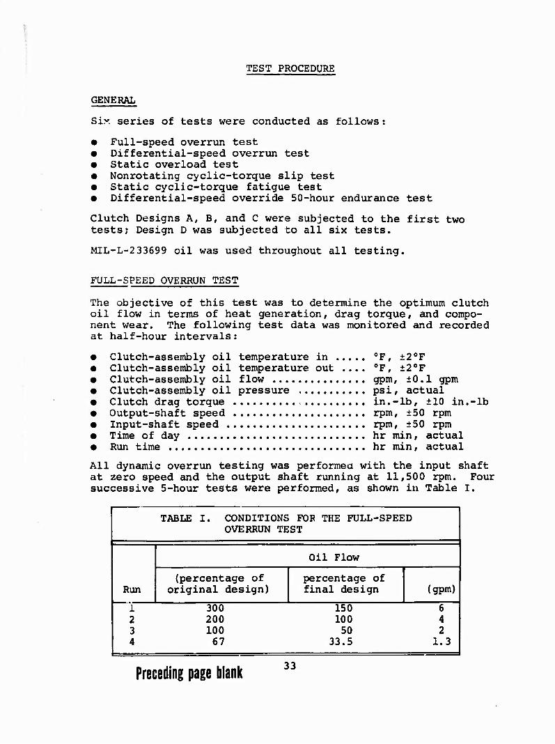
All dynamic overrun testing was performea with the input shaft at zero speed and the output shaft running at 11,500 rpm. Four successive 5-hour tests were performed, as shown in Table I.
TABLE I. CONDITIONS FOR THE FULL-SPEED OVERRUN TEST
Run
Oil Flow
(percentage of original design)
percentage of final design (gpm)
1 2 3 4
300 150 200 100 100 50 67 33.5
6 4 2
1.3
Preceding page blank 33
The oil temperature into the clutch was maintained at 200oF, ±2°, for all test runs. At the completion of each 5-hour run, the bearings, clutches, and inner and outer races were in- spected for any discrepancies. One clutch of each Designs A, B, C, and D was subjected to the full-speed overrun test.
DIFFERENTIAL-SPEED OVERRUN TEST
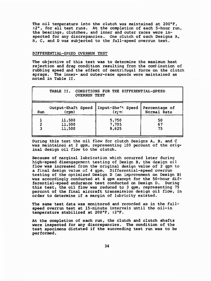
The objective of this test was to determine the maximum heat rejection and drag condition resulting from the com) ination of rubbing speed and the effect of centrifugal force on the clutch sprags. The inner- and outer-race speeds were maintained as noted in Table II.
TABLE II. CONDITIONS FOR THE DIFFERENTIAL-SPEED OVERRUN TEST
Run Output-Shaft Speed
(rpm) Input-Sha^t Speed
(rpm) Percentage of Normal Rate
1 2 3
11,500 11,500 11,500
5,750 7,705 8,625
50 67 75
During this test the oil flow for clutch Designs A, B, and C was maintained at 2 gpm, representing 100 percent of the orig- inal design oil flow to the clutch.
Because of marginal lubrication which occurred later during high-speed disengagement testing of Design B, the design oil flow was increased from the original design value of 2 gpm to a final design value of 4 gpm. Differential-speed overrun testing of the optimized Design D (an improvement on Design B) was accordingly conducted at 4 gpm except for the 50-hour dif- ferential-speed endurance test conducted on Design D. During this test, the oil flow was reduced to 3 gpm, representing 75 percent of the final aircraft transmission design oil flow, in order to determine if a margin of lubricity existed.
The same test data was monitored and recorded as in the full- speed overrun test at 15-minute intervals until the oil-in temperature stabilized at 200oF, ±20F.
At the completion of each run, the clutch and clutch shafts were inspected for any discrepancies. The condition of the test specimens dictated if the succeeding test run was to be performed.
34

STATIC OVERLOAD TEST
The objective of this test was to determine the ultimate capacity of the clutch and the mode of an overload failure. This test was performed on the selected candidate clutch only. Design D, as selected from the results of the previous test.
Static torque was applied in the following increments:
• 250 ft-lb from 0 to 4,000 ft-lb • 500 ft-lb from 4,000 to 8,000 ft-lb • 2,000 ft-lb from 8,000 ft-lb to failure
The following test parameters were recorded at each torque setting:
• Torque ft-lb, ±10 ft-lb • Angular displacement degrees, ±0.5 degrees • Outer-shaft deflection over each
row of sprags—8 places inches, ±0.0005 inch • Load sharing between rows
of sprags percent, ±20 percent
The clutch, inner and outer races, and bearings were coated with Mobil 28 (MIL-G-81322) grease.
The load distribution or sharing characteristics of the clutch was determined by machining a groove in the clutch inner race between the two rows of sprags and installing strain-gauge torque bridges. The gauges were then encapsulated in EC2216 epoxy. The load-sharing torsion bridges were calibrated in two steps. First, one row of sprags was removed from the clutch and 27,750 in.-lb of torque was applied in increments of 5,550 in.-lb. The second step was a repeat of the first step with only the second row of sprags installed. The inter- action of compressive line contact strains with the torsion bridge was measured at 27,750 in.-lb.
NONROTATING CYCLIC-TORQUE SLIP TEST
The objective of this test was to determine the cyclic torque at which the clutch fails to reengage. This test was performed on the selected candidate clutch only. Design D.
A steady torque of 45,540 in.-lb and an alternating load of ±4,560 in.-lb were applied. The alternating torque was in- creased in increments of ±3,000 in.-lb and run for 5 minutes at each setting or until the clutch began to slip.
The following data was monitored and recorded at each load level:
35
Static torque load ,.. in.-lb, ±120 in.-lb Alternating torque load in.-lb, ±600 in.-lb Angular displacement degrees, ±5 degrees
STATIC CYCLIC-TORQUE FATIGUE TEST
The objective of this test was to determine the fatigue char- acteristics of the clutch. This test was performed on clutch Design D only.
A static torque of 91,000 in.-lb and an alternating torque of ±13,600 in.-lb were applied. The test was to run for 10 mil- lion cycles or until failure« The following data was recorded in 500,000-cycle increments:
• Torque loading in.-lb, ±120 in.-lb • Number of cycles ±1,000 cycles • Angular displacement degrees, ±5.0 degrees
50-HOUR DIFFERENTIAL-SPEED ENDURANCE TEST
The objective of this test was to determine the ability of the clutch to function properly under adverse flight conditions for a sustained period of time, to determine the wear charac- teristics and reliability, and to aid in the eventual estab- lishment of a life cycle of the clutch. This test was performed on the selected candidate clutch only.
Data monitored was the same as that for the full-speed over- run test and was recorded at half-hour intervals.
Modifications to each clutch design and test reruns were madf- in accordance with Boeing Vertol test-plan document D301- 10118-1 and were determined by the condition of the clutch and clutch races at the completion of the previous runs.
36

TEST DISCUSSION AND RESULTS
INITIAL CHECKOUT OF FIXTURE
The specimen clutch was housed between two tapered-roller bearings. During the initial assembly of the test-specimen cartridge, the bearings were installed with 0.005 to 0.001 inch of axial float. At the completion of a pretest run it was noted that there was light circumferential scoring on the tapered rollers and at the completion of the first 5-hour run, the bearing cage had failed as shown in Figures 20 and 21. Analysis of the failure indicated it was the result of the axial float and marginal lubrication. The assembly was modi- fied to allow a greater oil flow through the bearings. The axial float was eliminated, and the bearings were preloaded from 1 to 5 in.-lb of running torque. In addition to these steps, the bearing cages were glass peened and silver plated to increase their marginal lubrication capability. No further difficulties were experienced with the tapered-roller bearings.
DETERMINATION OF OPTIMUM DESIGN
DESIGN A CLUTCH (BORG-WARNER X137661)
Full-Speed Test Run
Run 1 (6 gpm) of the full-speed overrun test was successfully completed with wear of 0.005 to 0.002 inch noted on the out- side diameter of the outer drag strips in the area of contact with the clutch outer race. Inspection at the end of run 2 (4 gpm) revealed wear of 0.008 inch on the bend radii of the inner drag strips where they made contact with the clutch inner cage (Figure 22) . There had been very litter experi- ence with wear in this area on clutches currently in service with similar configurations. As a result of the excessive wear, the inner drag strips were replaced with lower spring- rate strips. The clutch was then subjected to 30 minutes at 6 gpm and 5 hours at 4 gpm flow. Inspection after this run showed no signs of wear. The clutch then completed run 3 (2 gpm) and run 4 (1.3 gpm) of the full-speed overrun tests with no signs of distress. Drag-strip wear was within the acceptable limits of 0 to 0.0005 inch as determined by final inspection.
Differential Overspeed Test
This testing was conducted at 2 gpm which represents 100 per- cent of the original design oil flow to the clutch. Testing on Design A clutch was terminated upon completion of run 1 of the differential-speed overrun test when it was noted that the sprags were scuffed at the inner-race contact and the clutch inner race exhibited at 0.0016-inch wear step (Figure 23) .
37
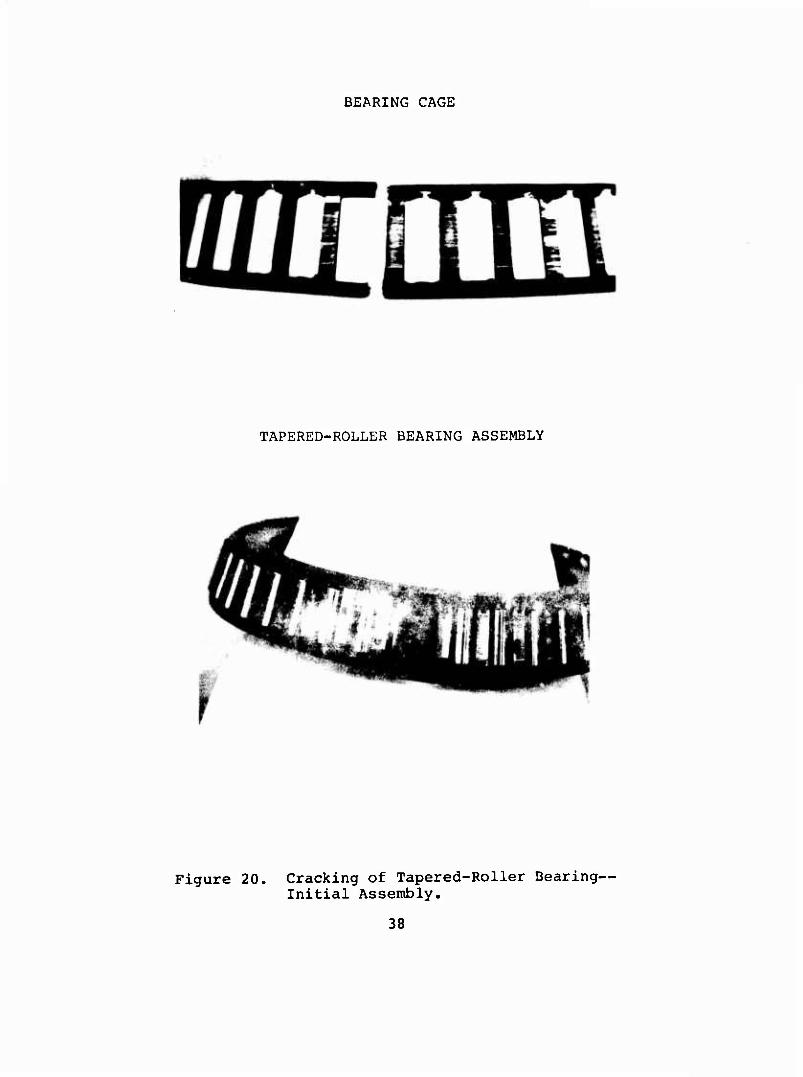
BEARING CAGE
TAPERED-ROLLER BEARING ASSEMBLY
Figure 20. Cracking of Tapered-Roller Bearing- Initial Assembly.
38

CIRCUMFERENTIAL SCORING AND EDGE LOADING ON ROLLER
^a»
EVIDENCE OF ROLLER SKIDDING ON INNER RACE
Figure 21. Surface Damage of Tapered-Roller Bearing,
39
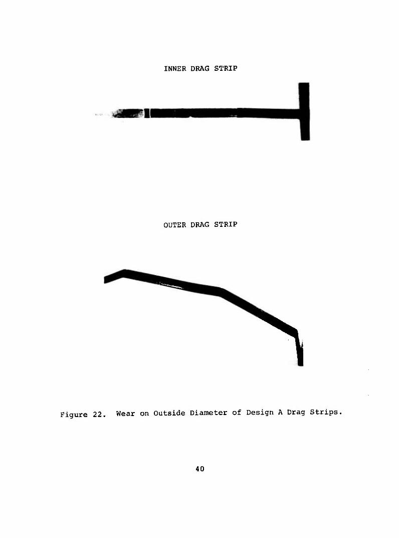
INNER DRAG STRIP
OUTER DRAG STRIP
Figure 22. Wear on Outside Diameter of Design A Drag Strips.
40
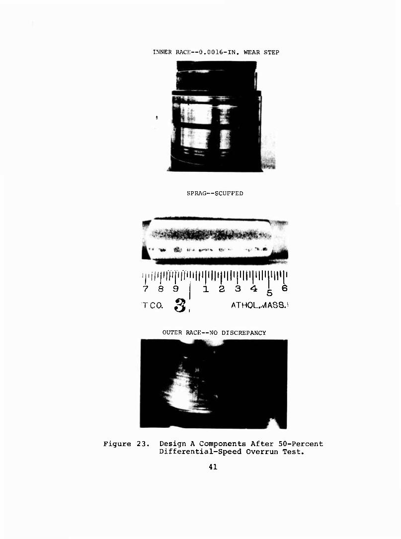
INNER RACK—0.0016-IN. WEAR STEP
SPRAG—SCUFFED
,,|ijij]i|i|Tiii||i 7 8 9 1
TCO. Oi
'il'l'll'l'll'l'll'l'li'l . 2 3 4 ^ €
ATHOUJASS,
OUTER RACE—NO DISCREPANCY
Figure 23. Design A Components After 50-Percent Differential-Speed Overrun Test.
41
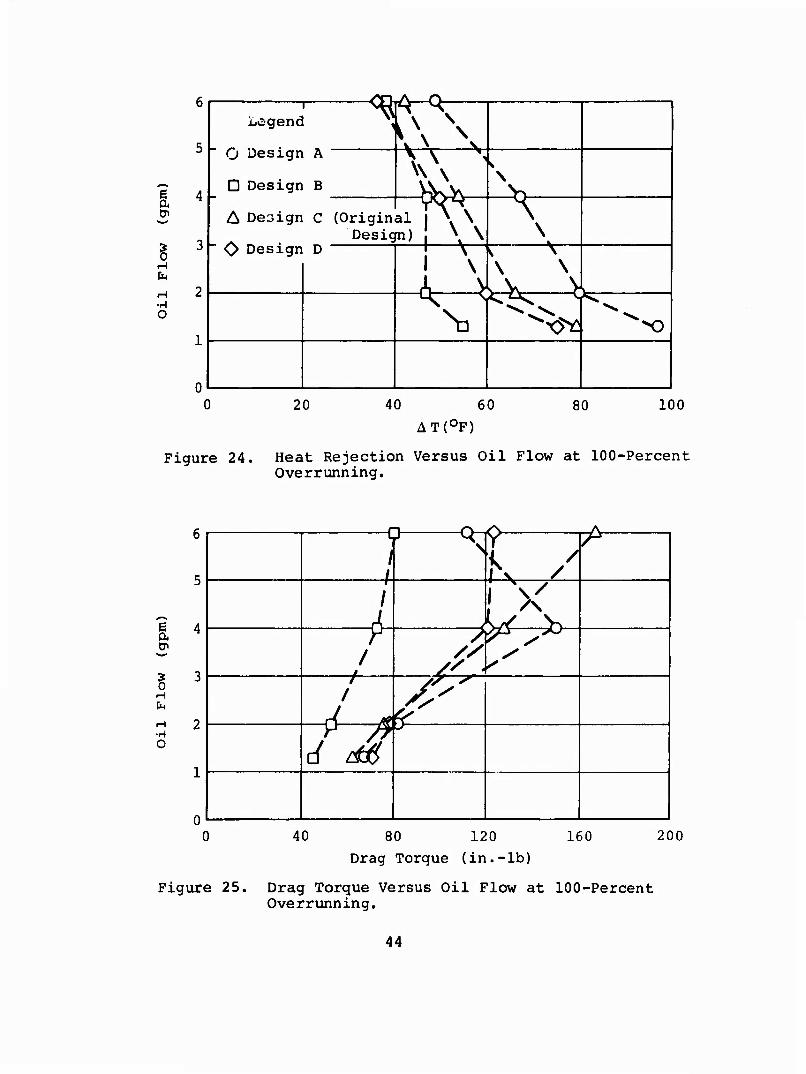
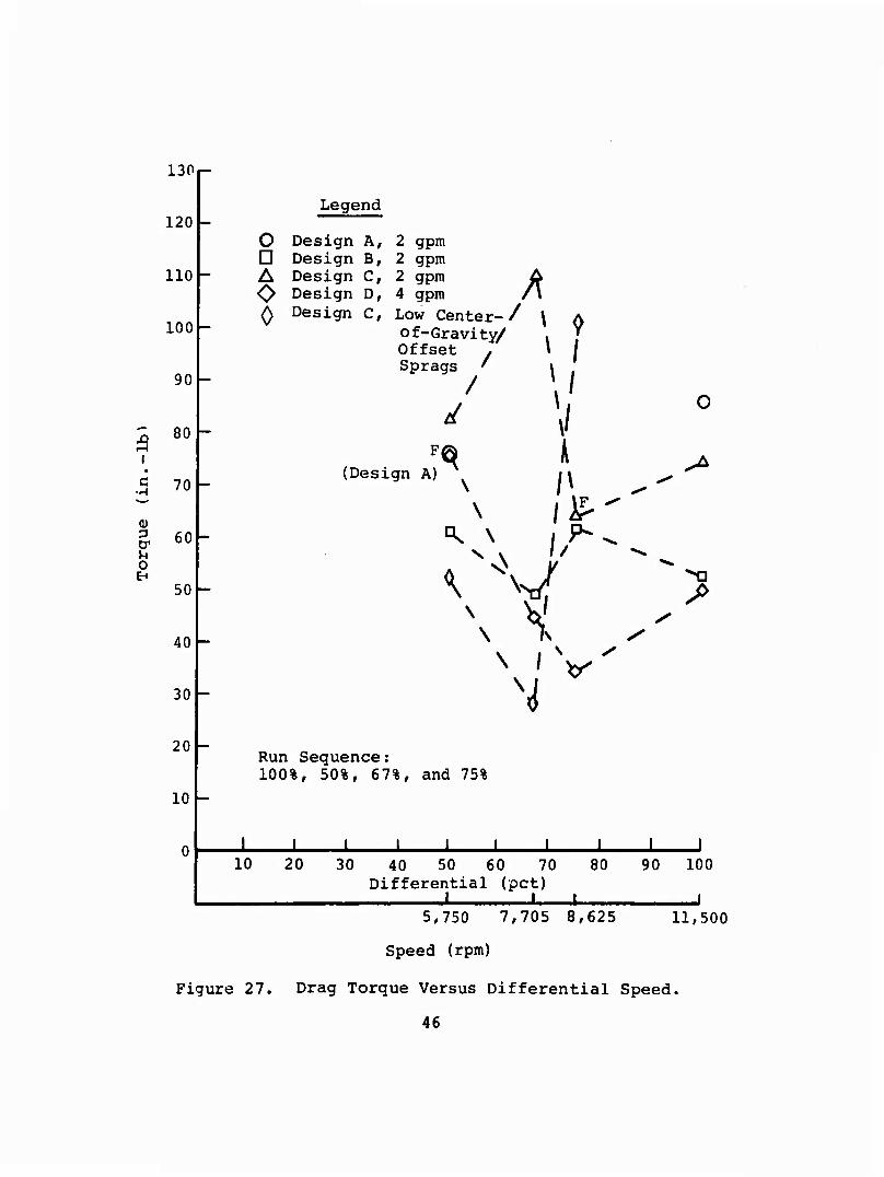
A test summary is shown in Table III. Inspection of the inner- drag-strip showed that wear was considerably reduced. Sprag scuffing is believed to be the result of a very high rubbing force on the inner race as exhibited by the high heat-rejection rate and high drag torque shown in Figures 24 through 27.
DESIGN B (BORG-WARNER X137675)
Full and Differential Speed Tests
As originally received, Design B contained sprags having the same strut angle as Design A. Since the results of the pre- vious test (Design A) indicated that the rubbing force was too high, sprags with a lower center-of-gravity offset were in- stalled before starting tests on this design. This clutch successfully completed all full and differential overrun tests, as shown in Table III.
Additional Nonscheduled Testing
The completion of this testing, an additional test at 2 gpm was performed to determine if the clutch would become centrif- ugally disengaged at high speed due to the low center-of-gravity offset sprags. Disengagements and re-engagements were success- fully accomplished at speeds from 7,600 to 9,500 rpm. Due to greater rubbing forces at higher speeds and the fact that there were no provisions for the application of an external force to initiate the disengagement, slippage could not be induced at speeds above 9,500 rpm. 'inspection at the completion of this test revealed a 0.0005-inch wear step on the inner race under one row of sprags only, shown in Figure 28; there were no ap- parent discrepancies on the second row of sprags. A dimensional inspection of the clutch by the manufacturer indicated that there was no geometric or metallurgical discrepancy apparent on the sprags, and that th light scoring under one row of sprags could possibly be attributed to foreign debris and/or slightly marginal lubrication.
The marginal oil was attributed to the adjacent oil retainer (ST40869-2) with the ID being larger than the clutch shaft (ST40872-1) inner race OD (Figure 10). Thin oil retainer to shaft clearance was necessary to allow assembly and disassembly operations. Ideally, the clearance between the oil retainer and shaft should be small enough to keep sufficient oil in the clutch area. However, optimum clearances could not be obtained in that dam, since,reducing the clearances would have meant damaging the clutch inner-race on assembly. The alternative of this solution was to increase the amount of oil flow to the clutch from the original design valae of 2 gpm to 4 gpm which was the final design value of oil flow to the clutch.
Of the three designs tested. Design B exhibited the best per- formance as is evidenced by the drag torque and heat rejection rates shown in Figures 24 through 27.
42

H H H
a a
u
| •H
C ■rH
c c 3
Q
I' to 0) Q
C D^
•H OJ
(U Q
U -d (U u tJi
•H
ß O U 0)
M O O 4J
CO
03
ß
•H
0) Q
Q) M 3 Di
•H
ß 0 u 0) Pi
u o -M
in in in m
m in in
in in m m
in
m
in
4J to 0)
+J CO
0)
§ M M 0) > o -a 0) 0) a, w i
3 CM
PM
■H o
o vo
I
I
B
•H o s
I I
ß 3 PS
H CM
I-I CM
•H rH o •H o a
(U 2 o & O n <N
1 1 1 1
ß ß 3 3 « P<
in (N
m (N
CD u
ß
0) S CO (U o <u CUrHQ
■HI
-0 "O -0 0) o 0) 0) d) 0) a Q. a w W w ß ß ß tp tP Cn
•H •H •H CO CO CO Q) 0) 0) Q Q Q
■P ■P ■p U u u 04 CU a<
•H O IJI ^
ß a-«»' 0) Cn U U-P 0) (t>
IW «N
•H +) ß Q ITJ «J
VO I I
in
I l
(* X Oi
o in
-0 (1)
H 0) •H 0. o w s ß
CO ^< 0)
Q ■P (0 +1
U ß Pi
PJ in r»
0)
ß ß nJ to M
ßH W CM
CO 0,
•H M P CO
'S o H
I M
O
CM >
CO
(0 & +J -H co u (U -P M CO
+J 0> ß «o (1) M
i^5 bi U id 0) o^ ß ß ß W -H
H TJ (0 (U ß o -a 0 «J 0) H H rH P tu •H H ü! (0 TJ PJ CM g.
CO C7> (0 M
CO
p <u CO
14-1 14H
o >1 p •rt > (0 M CP I
iw O I u P ß a) o
P •H
CO
0) -ß u p 3
-a 0)
to p CO
ß
43
E
§
•H O
Lc-gend
O Design A
D Design B
T\^ \
A Design C (Original ( ». \ Design) | \ \i
O Design D p-! \—^^ I
\ \
V-4^-^ \] x^ X)
20 40 60
AT(0F) 80 100
Figure 24. Heat Rejection Versus Oil Flow at 100-Percent Overrunning.
e
H CM
H 2
O
i
^-^^
df d£
<*$
JV-v^ /
i X
/: *7^
CA-
40 80 120 Drag Torque (in.-lb)
160 200
Figure 25. Drag Torque Versus Oil Flow at 100-Percent Overrunning.
44

Legend
O Design A D Design B A Design C ODesign D ^Design C
2 gpm 2 gpm 2 gpm (Original Design) 4 gpm 2 gpm (low CF Sprag)
F = Failure Test Terminated
Differential
(pct)
11,500 r 100
90
8,625
? 7,705
u
0) 0) 0-5,750
80
70
60
- 50
40
30
20
10
-«'
^ S
^\
"t^ M-\ 1 \
^
/ S
-T- s
s p^
Run Sequence 100 pct 50 pct 67 pct 75 pct
20 40 60
AT(0F)
80 100
Figure 26. Heat Rejection Versus Differential Speed Overrunning.
45
3 i
130
120
110
100 -
90 -
80
C 70
& 60 u o E-i
50
40
30
20
10
o D A O 0
Legend
Design A, Design B, Design C, Design D, Design C,
2 gpm 2 gpm 2 gpm 4 gpm Low Center- / of-Gravity/ Offset y Sprags '
/
A
\
(Design A) «* \
\
\
^
I I
»I
k
0
/
V
Run Sequence: 100%, 50%, 67%, and 75%
I J. J. ± -L JL -L -L 1 10 20 30 40 50 60 70 80 90 100
Differential (pet) I I ■ ■
5,750 7,705 8,625 11,500
Speed (rpm)
Figure 27. Drag Torque Versus Differential Speed.
46

Figure 26. Design B Clutch Shaft Exhibiting 0.0016-Inch Wear on Inner Race After Disengagement Test.
DESIGN C (FORMSPRAG CL-41802)
Full and Differential Speed Overrunning Tests
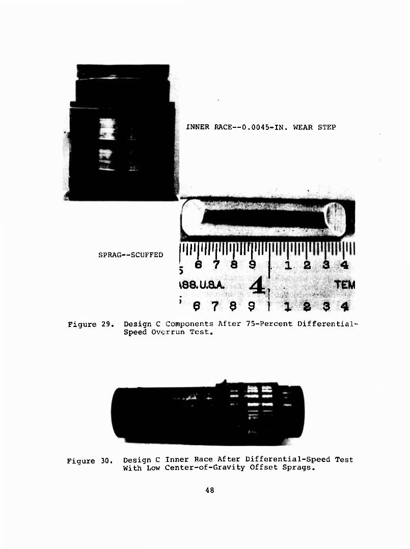
Design C successfully completed all of the full overrun and runs 1 and 2 of the differential-speed overrun tests, as indicated in Table III. At the completion of the third differential-speed overrun test, the clutch inner race was severely scored, with 0.0045 inch of wear step and the inside diameter of the sprags was scuffed (Figure 29). The distress on the clutch and inner race is indicative of high rubbing forces. Testing on this configuration was terminated and a new set of clutches incorporating standard garter springs and sprags with a lower center-of-gravity offset were installed. Run 3, the 75-percent differential-speed overrun test, was again performed. Inspection at the completion of this test revealed light polishing of the inner race; however, there was no measurable wear or sprag distress (Figure 30) .
Additional Testing
A test to determine if the clutch would become centrifugally disengaged was performed at input shaft speeds from 6,800 to 11,500 rpm. The clutch did not disengage; however, during a routine test-stand shut down, it was noted that at approxi- mately 860 rpm input speed, the clutch slipped and then re- engaged at about 470 rpm. Two additional shutdowns were effected with the same results; however, at the completion of the high-speed disengagement test, this phenomenon did not occur. Before removal at the completion of the high-speed
47
INNER RACE—0.0045-IN. WEAR STEP
SPRAG—SCUFFED i||<pi|ifi||i|i||r|i||i .6789
J 9 7 9 9 I i,
1 2 3 4 TEM
2 3 4 TL
Figure 29. Design C Components After 75-Percent Differential- Speed Overrun Test,
Figure 30. Design C Inner Race After Differential-Speed Test With Low Center-of-Gravity Offset Sprags.
48
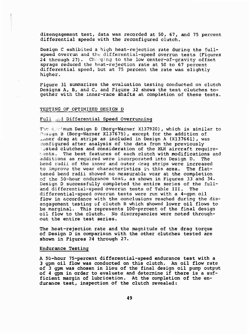
disengagement test, data was recorded at 50, 67, and 75 percent differential speeds with the reconfigured clutch.
Design C exhibited a high heat-rejection rate during the full- speed overrun and thy differential-speed overrun tests (Figures 24 through 27). Ch. -gJng to the low center-of-gravity offset sprags reduced the heat-rejection rate at 50 to 67 percent differential speed, but at 75 percent the rate was slightly higher.
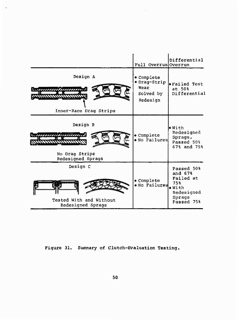
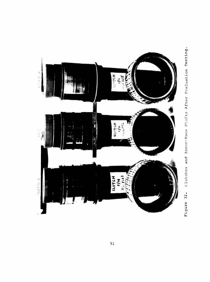
Figure 31 summarizes the evaluation testing conducted on clutch Designs A, B, and C, and Figure 32 shows the test clutches to- gether with the inner-race shafts at completion of these tests.
TESTING OF OPTIMIZED DESIGN D
Full ~:.d Differential Speed Overrunning
The c Hmum Design D (Borg-Warner X137920) , which is similar to fVisign B (Borg-Warner X137675) , except for the addition of .Lxiner drag at strips as included in Design A (X137661) , was configured after analysis of the data from the previously _sted clutches and consideration of the HLH aircraft require-
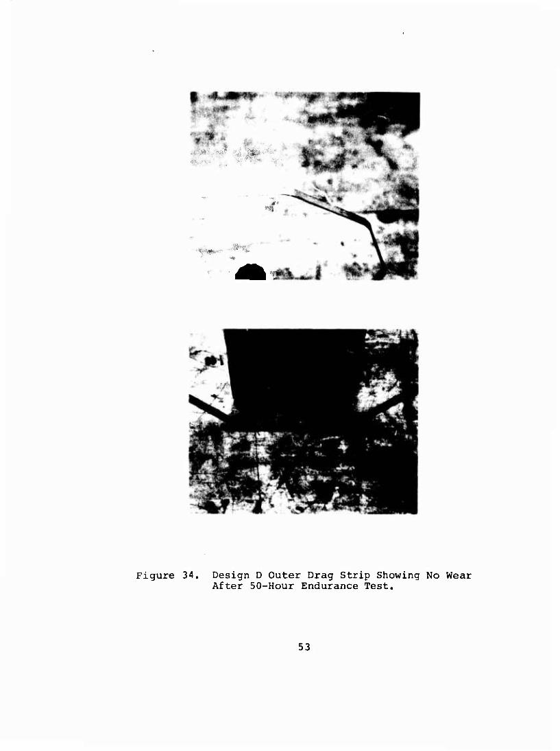
' ints. The best features of each clutch with modifications and additions as required were incorporated into Design D. The bend radii of the inner and outer drag strips were increased to improve the wear characteristics in this area. The flat- tened bend radii showed no measurable wear at the completion of the 50-hour endurance test, as shown in Figures 33 and 34. Design D successfully completed the entire series of the full- and differential-speed overrun tests of Table III. The differential-speed overrun tests were run with a 4-gpm oil flow in accordance with the conclusions reached during the dis- engagement testing üf clutch B which showed lower oil flows to be marginal. This represents 100-percent of the final design oil flow to the clutch. No discrepancies were noted through- out the entire test series.
The heat-rejection rate and the magnitude of the drag torque of Design D in comparison with the other clutches tested are shown in Figures 24 through 27.
Endurance Testing
A 50-hour 75-percent differential-speed endurance test with a 3 gpm oil flow was conducted on this clutch. An oil flow rate of 3 gpm was chosen in lieu of the final design oil pump output of 4 gpm in order to evaluate and determine if there is a suf- ficient margin of lubrication. At the completion of the en- durance test, inspection of the clutch revealed:
49
Full Overrun Differential Overrun
Design A
\^XVJ**NSN**C^N>WV^
\
• Complete • Drag-Strip
Wear Solved by
Redesign
•Failed Test at 50% Differential
Inner-Race Drag Strips
Design B
\>*}>}}}}}}}})m7777nj¥X ^*^V***X*NiN*^^
No Drag Strips Redesigned Sprags
Complete No Failures
• With Redesigned Sprags, Passed 50% 67% and 75^
Design C
• Complete • No Failures
Tested With and Without Redesigned Sprags
Passed 50% and 67% Failed at 75%
• With Redesigned Sprags Passed 75%
Figure 31. Summary of Clutch-Evaluation Testing.
50
c •H ■P m
c 0
•H ■P 03
iH
t> W
tu +J in <
a; -p IH rj x; a,
o u to a
i
0) c c
C rO
(.0
O
x: u
o
n
(1) M
Cn •H
51
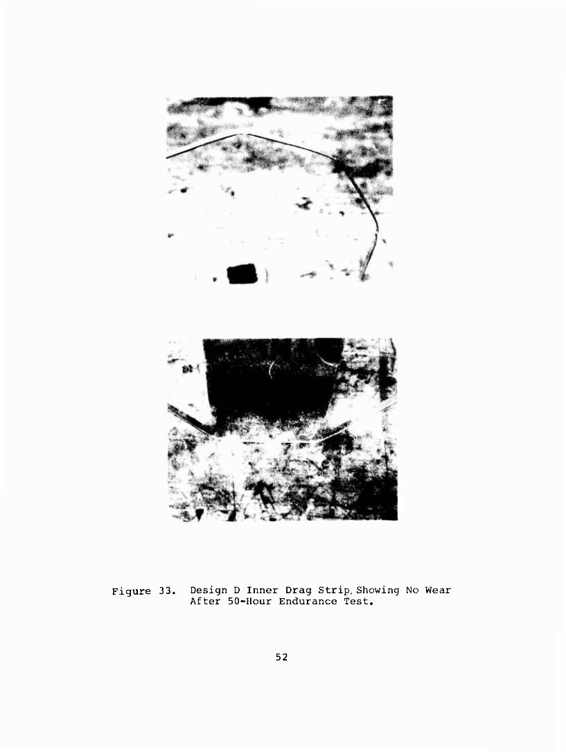
Figure 33. Design D Inner Drag Strip,Showing No Wear After 50-Hour Endurance Test.
52
• !
Figure 34. Design D Outer Drag Strip Showing No Wear After 50-Hour Endurance Test.
53
• A 0.0002-inch wear path on the inside diameter of the sprags
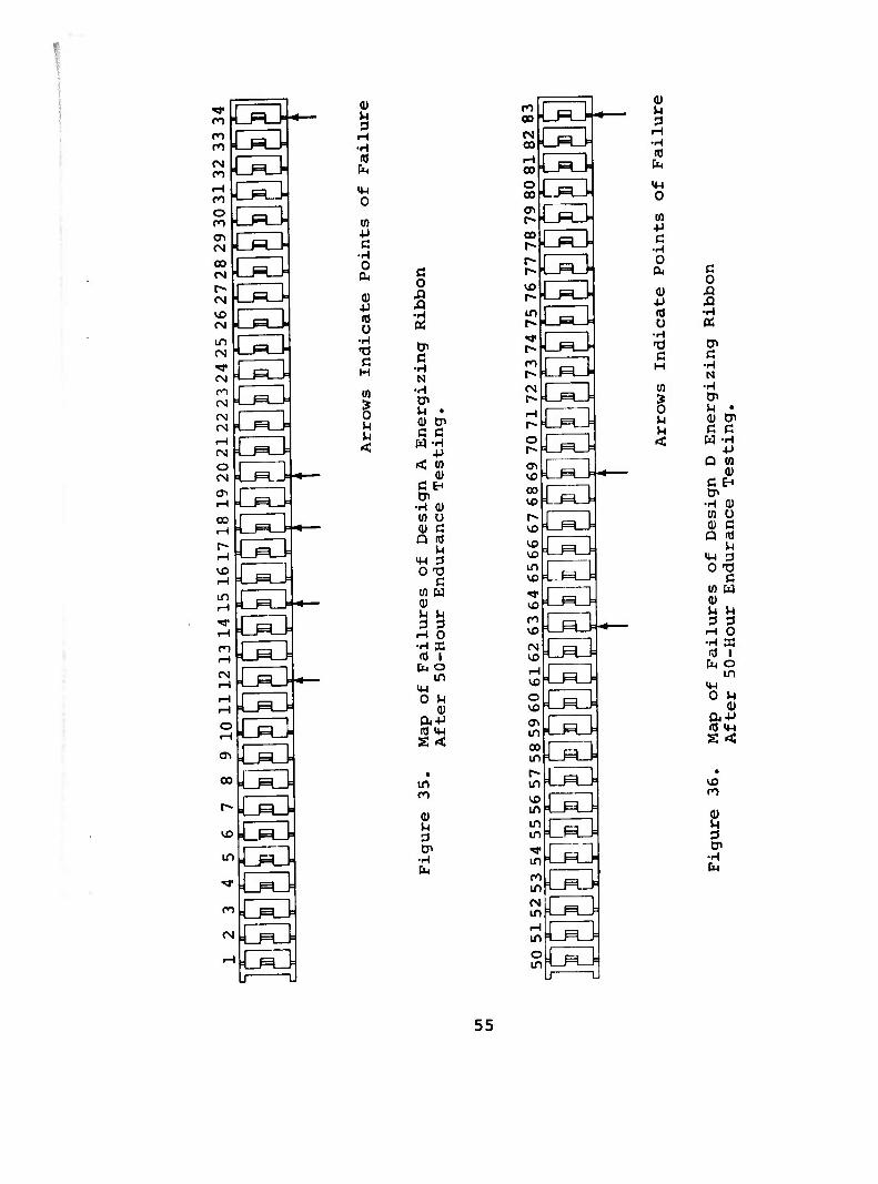
• Several breaks in the energizing ribbons (Figures 35 and 36)
• No wear on the clutch inner race (Figure 37)
The indexing of the energizing ribbons and inner and outer cage pockets was checked and found to be within tolerance. The en- ergizing ribbon radii were checked and found to be slightly iregular.
Static Testing
In addition to the dynamic testing performed on the candidate clutch. Design D, the following tests were performed. For the nonrotating cyclic-torque slip test, the clutch assembly and bearings were packed in MIL-G-81322 grease. During the initial loading and instrumentation systems checkout with a static load of 45,540 in.-lb and an alternating load of ±4,560 in.-lb applied, slippage occurred immediately. The loads were in- creased to 91,000, in.-lb ±9,000 in.-lb, and slippage contin- ued to be excessive. The clutch assembly was removed, disas- sembled, and degreased; inspection revealed no discrepancies. The test cartridge was reassembled using the same parts but using MIL-L-780 8 oil as a lubricant. The slippage rate had improved but not to the point of satisfaction, and a second disassembly and inspection was performed; no significant wear was apparent. A new clutch and inner race were assembled and reinstalled in the test stand. The new assembly was lubricated with MIL-L-7808 oil. Retesting showed that the slip rate had decreased over the previous clutch assemblies (Figure 38).
A frequency sweep from 10 Hz to 30 Hz with 91,000 in.-lb steady and ±9,000 in.-lb alternating torque applied was performed to determine if a resonant condition existed, thereby causing the slippage. No angular displacement between the inner and outer races was indicated. There was no amplitude or phase shifts throughout the entire sweep indicating that no detrimental resonance was present within the limits checked.
Because Design D was not available for test at this time and the geometric configuration of the cages, sprags, energizing ribbons, and drag strips of clutch Design A were similar to those ordered for Design D, all of the above static testing was performed on Design A.
At this point it was decided to hold the nonrotating cyclic- torque slip test in abeyance until Design D was received and to proceed to the nonrotating cyclic-torque fatigue test. This test was performed with a steady load of 91,000 in.-lb and an alternating torque of ±13,600 in.-lb applied to Design A. It was noted that the slip rate decreased as the cyclic count in- creased beyond 250,000. At 500,000 cycles, slippage stopped
54
m
oa
<y\
0) U
H •H m
4J c
•H 0
o •H ti C H
U)
B u u <
k^3 CS
c o
C •H N
•H Cr> U 0) c w
c •H in 0) Q
C ■H
W 0) En
0) U C
d
c 0)
o
u 3 H •H (0
M-l o
0)
in
(1)
00
tsa
CS3
<Ti
CB
Ci3 GO
0) u 3
r0
m o
^3 c
■H o
0) +J
Ü •H
c
B u
c o
•H «
c •H N
•H Cn u a) C W
c •H to (1) Q
C •H -P Ul (1)
ü c u
C
(Ü
IM o
rH •H
O
U
s B o in
M
a <
PL4
55

Figure 37. Design D Inner Race, Showing No Wear After 50-Hour Endurance Test.
30
40
a o CM
■P
c K
CO 0) •p 3 c •H
un \ a
■H
w i« 10 0
0) 0)
a
Steady Loading -9] ,000 In.-Lb
Single Poinl t Only
'v/l y^ 1
1 '
Build 1
k^ rj^^ l 6 9 12
Peak Dynamic Loading (in.-lb x 10"^)
15
Figure 38. Results of Slip Test.
56
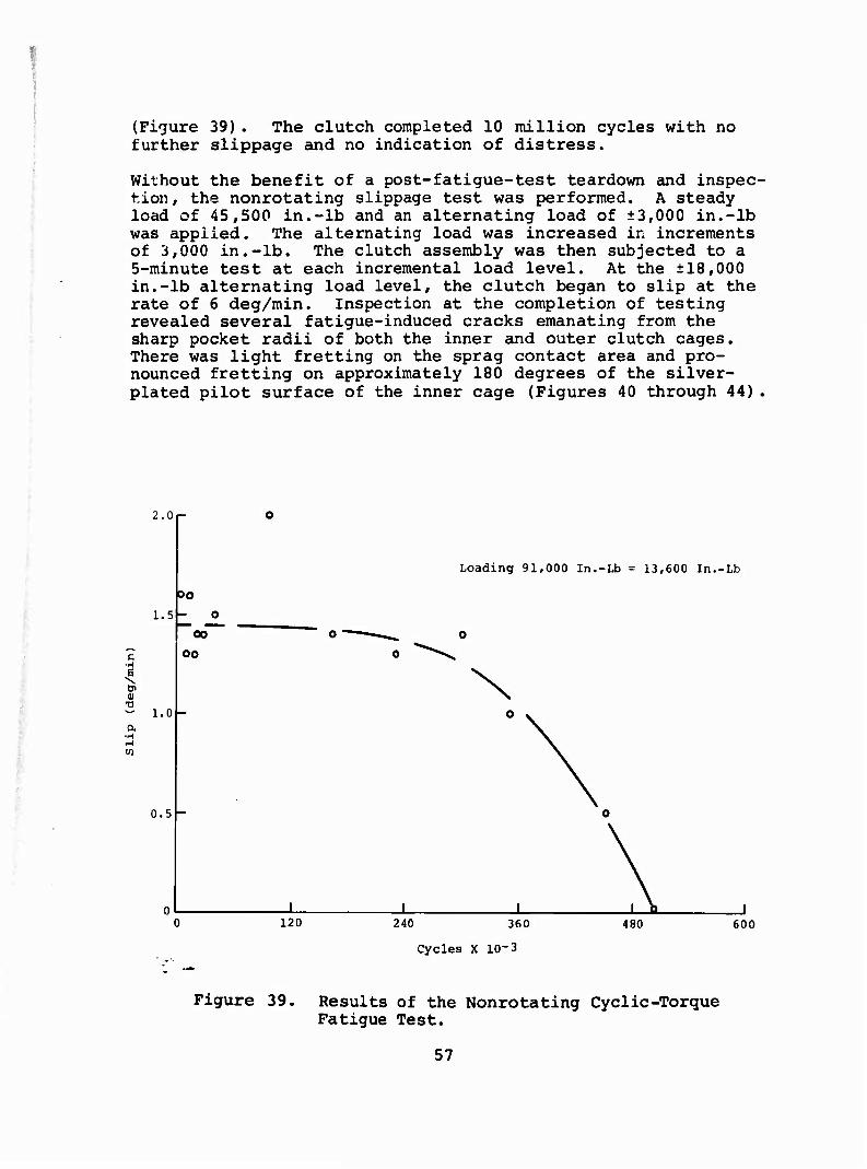
(Figure 39). The clutch completed 10 million cycles with no further slippage and no indication of distress.
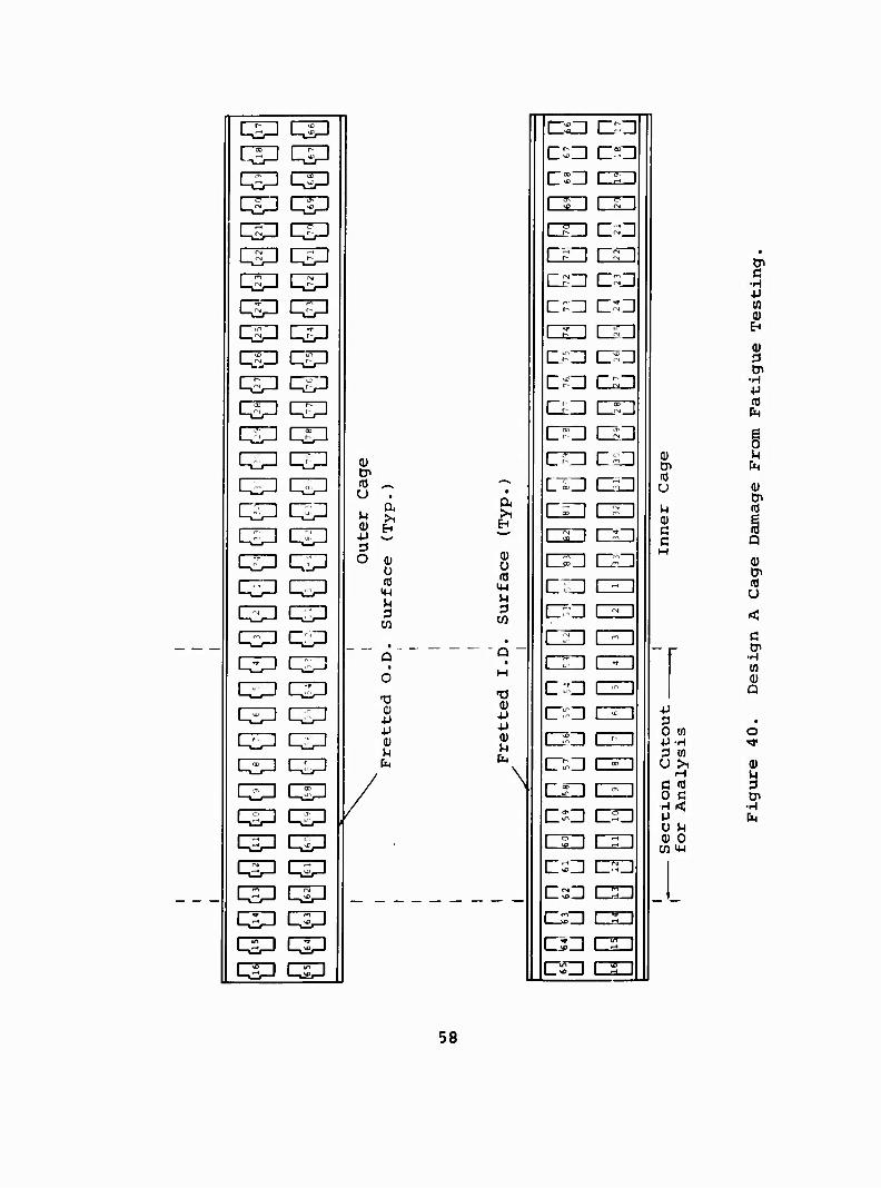
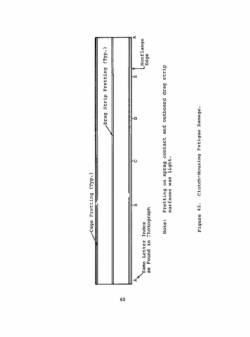
Without the benefit of a post-fatigue-test teardown and inspec- tion, the nonrotating slippage test was performed. A steady load of 45,500 in.-lb and an alternating load of ±3,000 in.-lb was applied. The alternating load was increased in increments of 3,000 in.-lb. The clutch assembly was then subjected to a 5-minute test at each incremental load level. At the ±18,000 in.-lb alternating load level, the clutch began to slip at the rate of 6 deg/min. Inspection at the completion of testing revealed several fatigue-induced cracks emanating from the sharp pocket radii of both the inner and outer clutch cages. There was light fretting on the sprag contact area and pro- nounced fretting on approximately 180 degrees of the silver- plated pilot surface of the inner cage (Figures 40 through 44)
■ ;
2.0
1.5
c -H
i -a - 1.0 a
•H
oo o
00
0.5 -
Loading 91,000 In.-Lb = 13,600 In.-Lb
\
120 240 360 480 600
Cycles X 10-3
Figure 39. Results of the Nonrotating Cyclic-Torque Fatigue Test.
57
CTH qp
qp qP q^D qp qp qp qsn qiP
q^ qp qsp qp qp q-n ^P qp
qp qp qp qp q£P q^ qp qp 133 qp qp qp qp qp qp qp qp qp qp qp qp qp qp qp qp qp qpi qp qpi qp qp qp qp qp qp qp qp qp
tn
U
U OJ 4J
o
EH
0
14-1 M 3 W
"0 tu
+J 4J
u b
era
CHI]
CSU CSU CSU CSD CSZI CSD OD CSD ca nn
Di c •H +J (0 0) n 0) 3 Cn
•H +J aJ P4
g 0) M Dl fe BJ U a)
CP M nJ (U C i C Q M
Q) &« fl Ü
< C _ ,_ CP
■H 03 OJ a
4J 3 * 0 tn 0 P-H •*< 3 M U >i (U
H C (0 S 0 c cn H< ■H p fo U M Q) 0
cn M-i
58

(0
ex" 0) M
c 0 H 4J
o u x: OJ & •p ■P c (U -H
(U c I 3 (0 0
CO o o
+J (0 E
■H X 0 M a
C •H -P -P (U M
tn
w-
Q-
a 1 >
EH CJi (0 p CP Q c
•H -P p ß +J (0 (U u u
•H fe 14-1
•H a c •H en u
•H p w en
TD M rO O XI OJ -P tji 3 -a ü w
c •H
w W •H
•H (U
(U U O (0 (0 M-l m ^ M 3 3 tfl w
+J -p m m 0) 0) m M 0 0 • 04
OJ • • u CP
TJ c 0 >i-H O XI -P Di ■p
cr> (u >iC u H ■M m H ■p (Ö +J 0) )H a) Cn a) p (Ö c m 0 0) Cn a) 0
p a 01 QJ
•H > w 0) nj
•p (0 ^ u aj u-i (U •P 0 p c (D 0 (0 j- u 0)
p ■P
t7>(d 0) aJ P M 0) a ax:x: w p >
■ •
0) -p 0 3
QJ
QJ 3 Cn
•H P
-P 4-1 (0
w I
u -p 3
rH u
2 3 Cn
•H tu
59
en c
■H -P 4-> (U u
0) Cn
\
" <U tP c '"" (d
6A I-I
C tP OT( 2 W
tT 4 I Cu •H
ß U ■H 4J -W ■P
(0 I -P 01 cn u (0 fe
t3 a •H T3 u M
(0 O
• 0)
Di 5 tn (0 m -Q 3
M 0 ■3 Q
\ -0
P o (0 •p c
Q
(U
■H p 03
-U
0 u . cnxl
cn c
•H to
0 X
1
(0 &> M -H
CO
c <0 1
p 0 »
tP 0) 0 H
C 0) ■H U U P (0 p IP
-03 0) P £ P 3 a b-i (n
u cn • •
0) p a Cn
•H fa
X 0 0) (U 4-1 p -a o 0 ex: 2 H (.,
Same Letter
as Found in
60
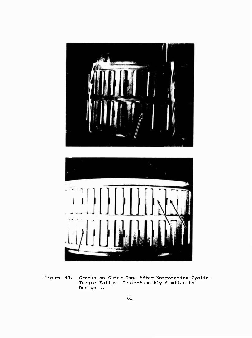
Figure 43. Cracks on Outer Cage After Nonrotating Cyclic- Torque Fatigue Test—Assembly S..milar to Design u.
61
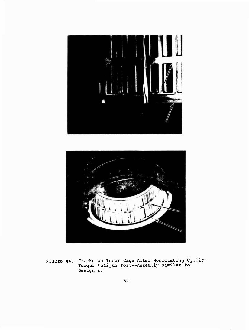
Figure 44. Cracks on Inner Cage After Nonrotating Cyclic- Torque ^atigue Test—Assembly Similar to Design u.
62
STATIC OVERLOAD TEST
This test was conducted on optimum clutch Design D only. The purpose of the test was to determine the clutch ultimate capac- ity. Static torque in the following increments was applied to the clutch by means of the test used in the previously de- scribed fatigue tests (Figure 18) :
• 250 ft-lb from 0 to 4,000 ft-lb • 500 ft-lb from 4,000 to 8,000 ft-lb • 2,000 ft-lb from 8,000 ft-lb to failure
Failure was defined as roll over, slippage, or component frac- ture. Testing on one assembly only was conducted. All clutch parts including bearings were coated with grease (MIL-G-81322).
The following data was recorded at each torque setting:
Torque ft-lb, ±10 ft-lb '\' nular displacement degrees, ±0.5 degree Outer-shaft deflection
over each row of sprags - 8 places total inches, ±0.0005 inch
Load sharing between rows of sprags percent, ±20 percent
All parts tested were used in previous overrunning and fatigue tests. All buildups for the static overload testing had less than 0.001-inch end-floating clearance. Subsequent teardowns revealed no change in this end clearance.
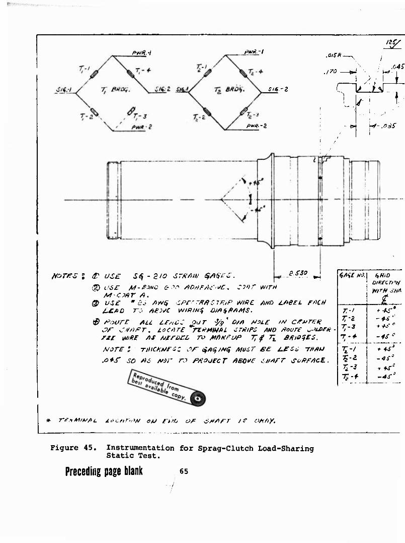
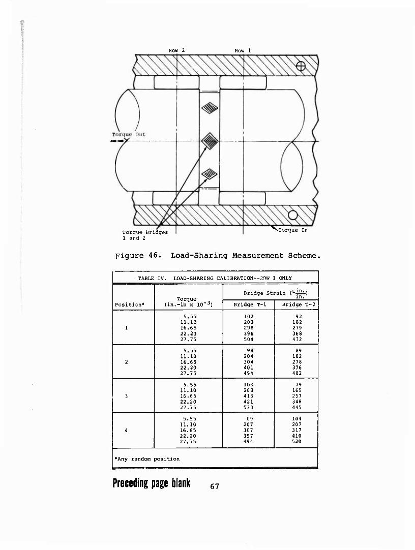
The load-sharing strain-gauged shaft (torsion bridge) , Figure 45, was calibrated in two steps. In step 1, only clutch row 1 was installed in the buildup. See Figure 46 for row 1 location. Torque calibration, presented in Table IV, was done to 50 per- cent normal flight loading. In step 2, clutch row 1 was re- moved and clutch row 2 was installed in the buildup. Interaction data of row-2 compressive line contact strains interacting with the torsion gauges was also collected to 50 percent normal flight load, as shown in Table V.
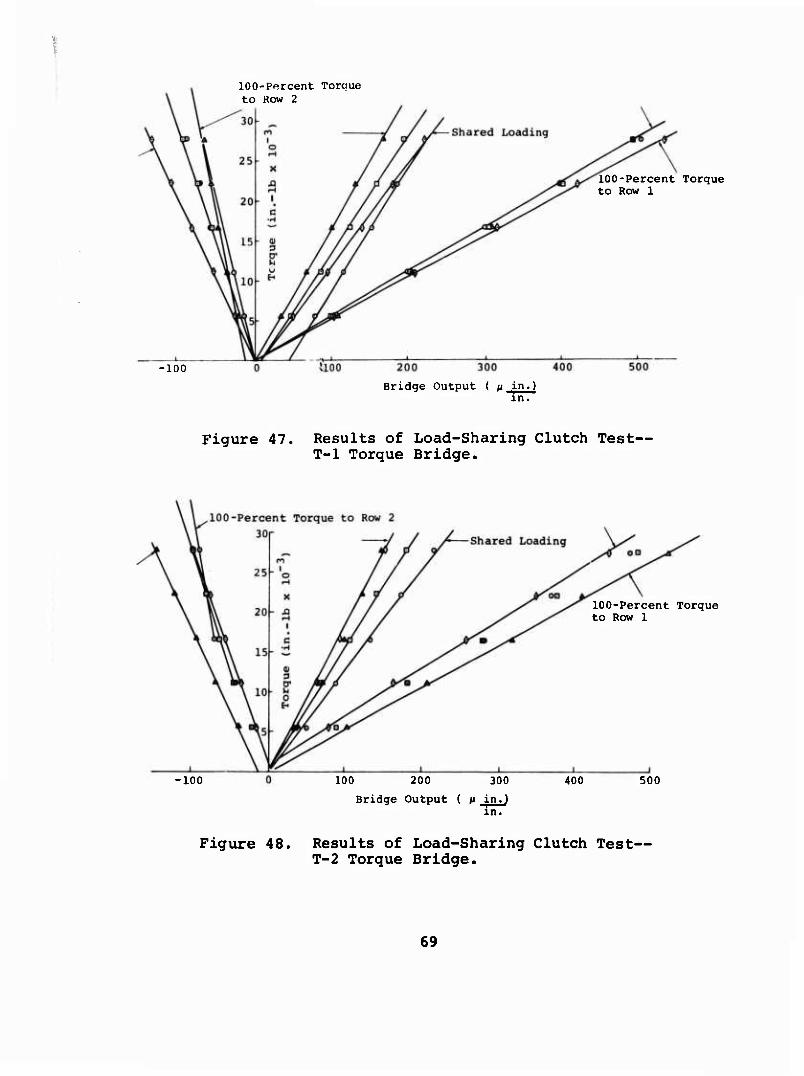
The load-sharing test was done at 50 percent normal flight load. See Table VI for this data. Figures 47 and 48 are plots of the load-sharing data.
At various torque increments, while increasing torque to reach ultimate clutch failure, housing radial-deflection measurements were made across each row of sprags at four diameter locations spaced 45 degree apart. See Table VII for this data. Failure occurred at a torque level of 206,900 in.-lb or 17,240 ft-lb, which is equivalent to 468 percent of one-engine design torque.
63
:
WR.-I pwA.-l .QlSK.
.170
SiS-Z ' ■ ^ ^li
.04S
t
p^.-a /■I
H«- .#*£
fares % £ USE *S30 * S$-ZIO STR'fiW SM'tS.
Q cor /Lf-j?Mc & ■">,-> ADrtFM'^c, conr WITH M-CMT A.
@ U3£ ' <?-- />)V(J CPCrfiflCTF.iP WR€ AHO LABEL fncti
LfsiC OUT 3/$ o/rt *3i£ //v cfvr/:? JV" CtfrtT* LOCHTE "rtfMMAL tTtitFS AND fiouTE >.JU>E*- ri£ WRE AS AJirüt-L ro MAHfi/P T; f TK SftOfES.
NOTE I TtUCHtJFSZ JT $*<$/*$ MUST ££ J.eS6 THAU
.o+S" so # 6 jvor ro PROJECT ABOVE tM/irr so PEACE..
S/li£ HO. (,H<0 oiftfcrfw W/rtf SNA
t T.-l + +S* t-z -4-i '' Z-3 i+S"
-4S*
t't ; is'
t'2- -4i-J
I Tfi f W T,-f -4*'
I ■■—
# 7-f.iM/vfii. j.L>cf>r':*H OJJ r^rj of SMAET i? oHny.
Figure 45. Instrumentation for Sprag-Clutch Load-Sharing Static Test.
Preceding page blank 65

ßZL .o/r/?.
.170 - v-* M?
riiLi t- i
•1 N*- .0iiS
Go'
X tr
♦t- -
iu.
w
.1
UfQ
IZO
9 SSO
±/>B£L FfiCH
JA/ C^vrEft
/.eSo THAU
^1 r.-t
Tr3
T'4- I
- 4i "'
-4S0
.4S0
-AS'
REVISIONS
LTR OtSCBIPTION DATE APPROVAL
it AHY OIL f/'l£ Nr*R $/>;/#$ t/NOtf-
30
\
0 330
IS'
vrw\ 1.^ / '.2 '-r i .
3M
/- .
^7- * cv '4 + \ '.. A. ^
d/o'
/ST>
Tr? D/fi^ #3Lr. TO
Zio
i/A (7
/w£ft / oorr» £inf£S ■fe D/fi. (yyp) oeduffR B>rH
ENGINEERING TEST
LABORATORY BJT^ TWTB-
P. N£$US f**C*
CMK I
APPO
DASM NO QTY MAIL SIZE 6- DESCRIPTION
THE jr^i VERTOL DIVISION
fX^^^ COMPANY PHILADELPHIA, PA.
Hin/Are OV£&*UfittN* SPftfiq CLUTCH INCTKUMI N 'S, -„ w
size
B CODE
IDCNT NO
77272 sr ao<o4-8
SCALE SHEET —7- 9g / J
-Sharing
Row 2 Row 1
Torque Bridges 1 and 2
vTorque In
Figure 46. Load-Sharing Measurement Scheme,
TABLE IV. LOAD-SHARING CALIBRATION--ROW 1 ONLY |
Bridge Strain (^iSi.) | Torque
(in.-lb x 10~3)
in. j
Position* Bridge T-l Bridge T-21
5.55 102 92 j 11.10 200 182
( 1 16.65 298 279 22.20 396 368 27.75 504 472 j
5.55 98 89 1 11.10 204 182 i
2 16.65 304 278 22.20 401 376 27.75 4S4 482 j
5.55 103 79 11.10 208 165
3 16.65 413 257 22.20 421 348 27.75 533 445 j
5.55 09 104 11.10 207 207
4 16.65 307 317 22.20 397 410 27.75 494 520
*Any random position j
Preceding page blank 67
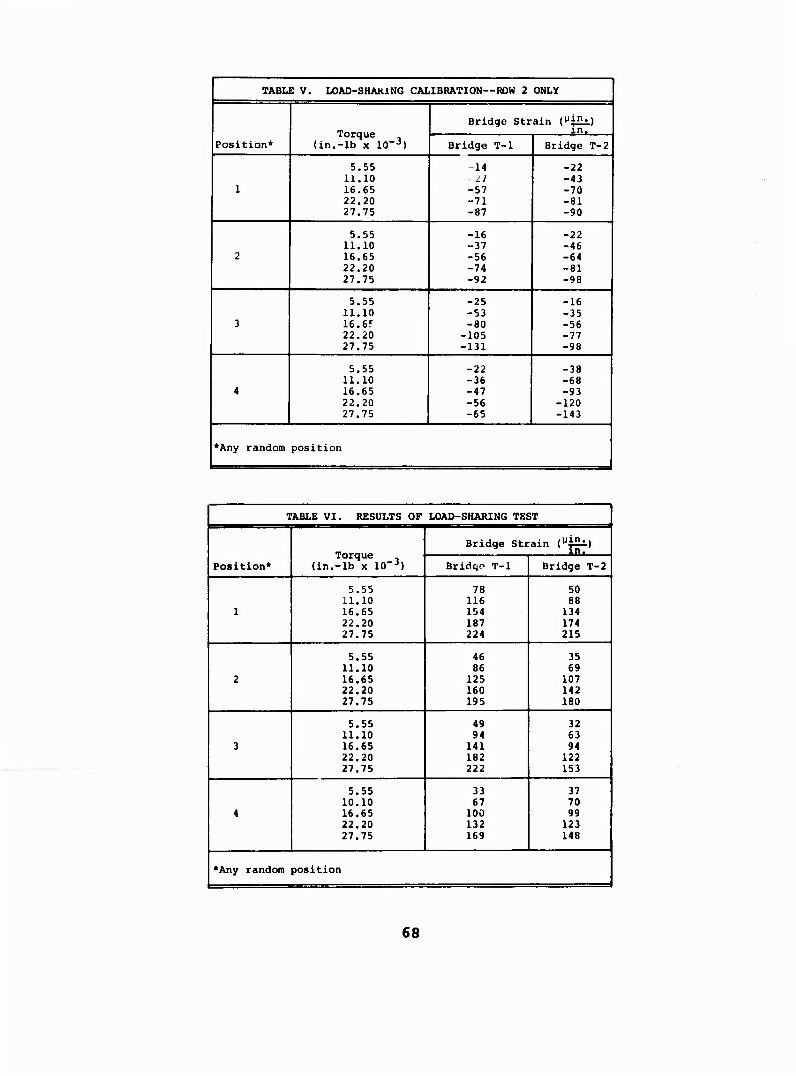
TABLE V. LOAD-SHAKING CALIBRATION—ROW 2 ONLY
Position* Torque
(in.-lb x 10"3)
Bridge Strain (^"v) in.
Bridge T-l Bridge T-2
1
5.55 11.10 16.65 22.20 27.75
-14 -11 -57 -71 -87
-22 -43 -70 -81 -90
2
5.55 11.10 16.65 22.20 27.75
-16 -37 -56 -74 -92
-22 -46 -64 -81 -98
3
5.55 11.10 16.6? 22.20 27.75
-25 -53 -80
-105 -131
-16 -35 -56 -77 -98
4
5.55 11.10 16.65 22.20 27.75
-22 -36 -47 -56 -65
-38 -68 -93
-120 -143
*Any random position
TABLE VI. RESULTS OF LOAD-SHARING TEST
Position* Torque
(in.-lb x lO-3)
Bridge Strain (^i^)
Bridqo T-l Bridge T-2
1
5.55 11.10 16.65 22.20 27.75
78 116 154 187 224
50 88
134 174 215
2
5.55 11.10 16.65 22.20 27.75
46 86
125 160 195
35 69
107 142 180
3
5.55 11.10 16.65 22.20 27.75
49 94 141 182 222
32 63 94
122 153
4
5.55 10.10 16.65 22.20 27.75
33 67
100 132 169
37 70 99
123 148
*Any random position
68
■100
100-Percent Torque to Row 2
U00
Bridge Output ( ß in.) in.
100-Percent Torque to Row 1
Figure 47. Results of Load-Sharing Clutch Test— T-l Torque Bridge.
•100
100-Percent Torque to Row 1
100 200 300 400 500
Bridge Output ( M in. in.
Figure 48, Results of Load-Sharing Clutch Test— T-2 Torque Bridge.
69
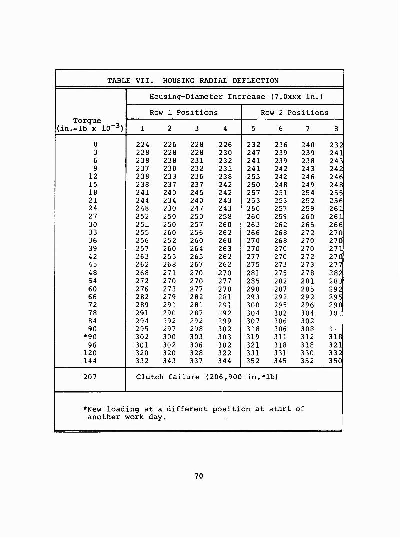
TABLE VII. HOUSING RADIAL DEFLECTION
Housing-Diameter Increase (7.0xxx in.)
Row 1 Positions Row 2 Positions Torque
(in.-lb x 10"3) 12 3 4 5 6 7 8
0 224 226 228 226 232 236 240 232 3 228 228 228 230 247 239 239 241 6 238 238 231 232 241 239 238 243 9 237 230 232 231 241 242 243 242
12 238 233 236 238 253 242 246 246 15 238 237 237 242 250 248 249 248 18 241 240 245 242 257 251 254 255 21 244 234 240 243 253 253 252 256 24 248 230 247 243 260 257 259 261 27 252 250 250 258 260 259 260 261 30 251 250 257 260 263 262 265 266 33 255 260 256 262 266 268 272 270 36 256 252 260 260 270 268 270 270 39 257 260 264 263 270 270 270 271 42 263 255 265 262 277 270 272 270 45 262 268 267 262 275 273 273 277 48 268 271 270 270 281 275 278 282 54 272 270 270 277 285 282 281 283 60 276 273 277 278 290 287 285 292 66 282 279 282 281 293 292 292 295 72 289 291 281 291 300 295 296 298 78 291 290 287 292 304 302 304 30;? 84 294 ?92 292 299 307 306 302 90 295 297 298 302 318 306 308 J» -'
*90 302 300 303 303 319 311 312 318 96 301 302 306 302 321 318 318 321
120 320 320 328 322 331 331 330 332 144 332 343 337 344 352 345 352 350
207 Clutch failure (206,900 in.- lb)
*New load ing at a different positi on at start of another work day.
70

The failure was sprag rollover. All sprag preload spring tabs but one were broken off. Also, several sprags had sheared "coffin corner" edges. Shaft and housing showed some brinel- ling. Unaided visual examination of the inner and outer cages revealed no damage (Figure 49) .
INNER RACE
SPRAGS AMD ENERGIZING RIBBON
SPRAG
3789 ,12341
Figure 49. Design D Components After Static Overload Test.
71

Table VIII shows the results of the load-sharing test and in- dicates that on the average, each row carries approximately 50 percent of the torque.
TABLE VIII. SUMMARY OF LOAD-SHARING TEST RESULTS
1
j Position3
Torque Through Row 1 (pet) 1
Torque Bridge 1 Torque Bridge 2
1 1
i 2
3
4
61.4
49.8
53.7
43.2
56.3 |
47.9
44.3
46.5 1
Average 52.0 48.8
Any random position
bIn the assembled position, row 1 is the first sprag-clutch row, looking from the engine end. |
72
CLUTCH ANALYSIS
The optimum test clutch, Design D (Borg-Warner X137920) , and the HLh aircraft clutch (301-10629) have been analyzed by the methods presented in the appendix. Geometrical data required for the analysis was taken from the appropriate clutch raceway and sprag drawings and is presented in Table IX. Although the data was taken from the X137920-S aircraft sprag drawing, the X133366 test-clutch sprag is identical with respect to those dimensions used in the analysis. For analysis purposes, nominal values of all dimensions have been used. Note that the test and aircraft clutch configurations are identical with the ex- ception of the outer-race thickness.
The results are presented in Figures 50 through 53. The curves extend to 100 percent cam rise, which indicates failure by sprag rollover. Table X presents the results as compared to the design criteria. The expected rollover torque for the air- craft clutch based on the test is also shown. Although this is slightly less than 450 percent torque, a problem with the air- craft clutch is not expected since the drive system ultimate torque is equivalent to 225 percent. Also, the outer-race hoop stress in the aircraft clutch is 3.5 percent above the criteria at 200 percent torque. However, since the test clutch com- pleted 10 million cycles during the fatigue test at a torque level equivalent to 206 percent, ±30.8 percent of aircraft single-engine torque without indication of outer race distress, and since the aircraft clutch operating condition is equivalent to 100 percent, ±12 percent, of single-engine torque, the slightly higher calculated hoop stress does not indicate an objectionable condition. Note also that at clutch rollover, the outer-race hoop stress is less than the race ultimate tensile strength.
73
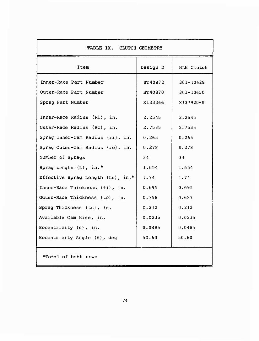
TABLE IX. CLUTCH GEOMETRY
j Item Design D HLH Clutch
Inner-Race Part Number ST40872 301-10629 j
Outer-Race Part Number ST40870 301-10650
Sprag Part Number X133366 X137920-S |
Inner-Race Radius (Ri), in. 2.2545 2.2545 1
Outer-Race Radius (Ro), in. 2.7535 2.7535
Sprag Inner-Cam Radius (ri), in. 0.265 0.265 |
Sprag Outer-Cam Radius (ro), in. 0.278 0.278
Number of Sprags 34 34
Sprag uongth (L), in.* 1.654 1.654 |
Effective Sprag Length (Le), in.* 1.74 1.74
Inner-Race Thickness (ti), in. 0.695 0.695
Outer-Race Thickness (to), in. 0.758 0.687 i i
Sprag Thickness (ts) , in. 0.212 0.212 j
Available Cam Rise, in. 0.0235 0.0235 j
Eccentricity (e), in. 0.0485 0.0485 j
Eccentricity Angle (9), deg 50.60 50.60
J
*Total of both rows
74
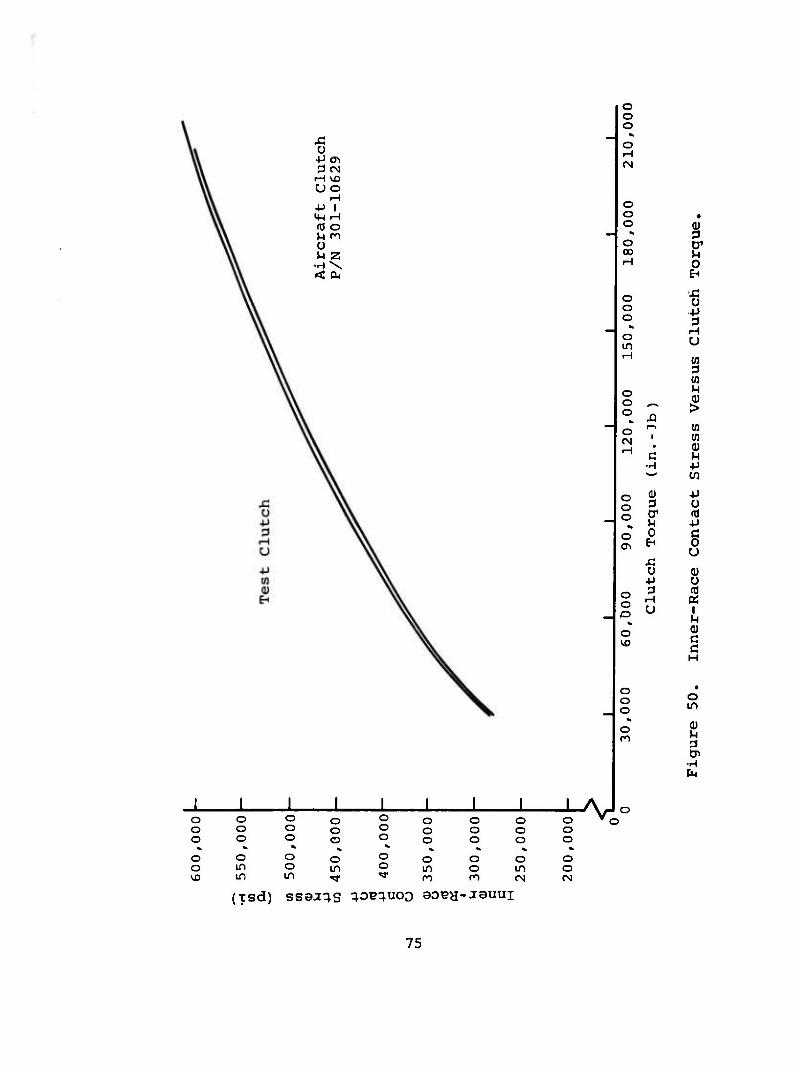
£ ü 4-1^ !3fN
rH VD UO
rH ■P 1 >W rH (ö o >H ro O H z •H\ < cu
o o o «> o rH CM
O O • O Q) * ^ o D1 00 ^l rH s O O O •P
3 ^ rH o
in U rH
3 o o o
XI
M 0) >
o CM
1 (0
rH •
c s •H +J w cn
o 0) ■p o 3 o o er (0
^ M +J o 0 c a\ EH 0
u U 0) +J ü
o o
3 rH U 1
u o
C! C H
o • o o
O in
^ o
•H CM
o o o o o o o o o o o o * ^ ^ « o o o o o in o in <D in in "<*
o o o o o
o o o o o o o o o o o o
% *k ^ ^ o o o o in o in o ro ro fN rg
V
(xsd) ssaa^s ^OH^UOO 90T?H-J9UUI
75
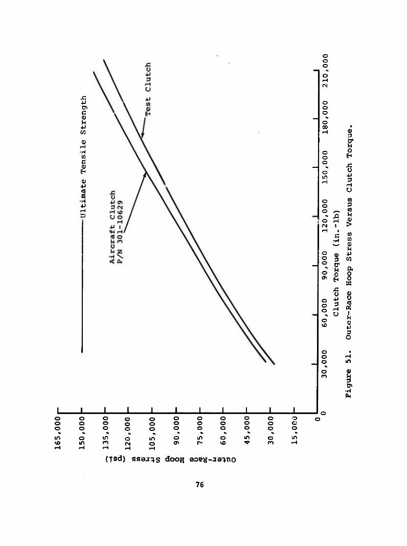
■M &> C (ü u 4J W
0) rH •H m C 0)
EH
0) •P
•H •P
o o o
N
o iH tN
O O O
% o 00 • rH
E1
O O
0 EH
o J5
o in H
O
rH U
o (0 o 3 o s^ U]
*> A >H o H 5! fN 1 > «H •
c (0 •H (0
2 O i) ■p O S w O O1 * u a o 0
E-" 8 33
O o o
ü +J
H
8
o U u
p
1 o t
o rH o in
% o 0) Cl
•H
O o o o o o o o o o o o o o o o o o o o o c; o o o o o o o o o o o *> % * « * * fe ^ % ^ « in o in o in o in o in o in vo in m rj o <T\ r«- vo ^r ro rH
(xsd) ssaj^s dooH aoca-ja^no
76
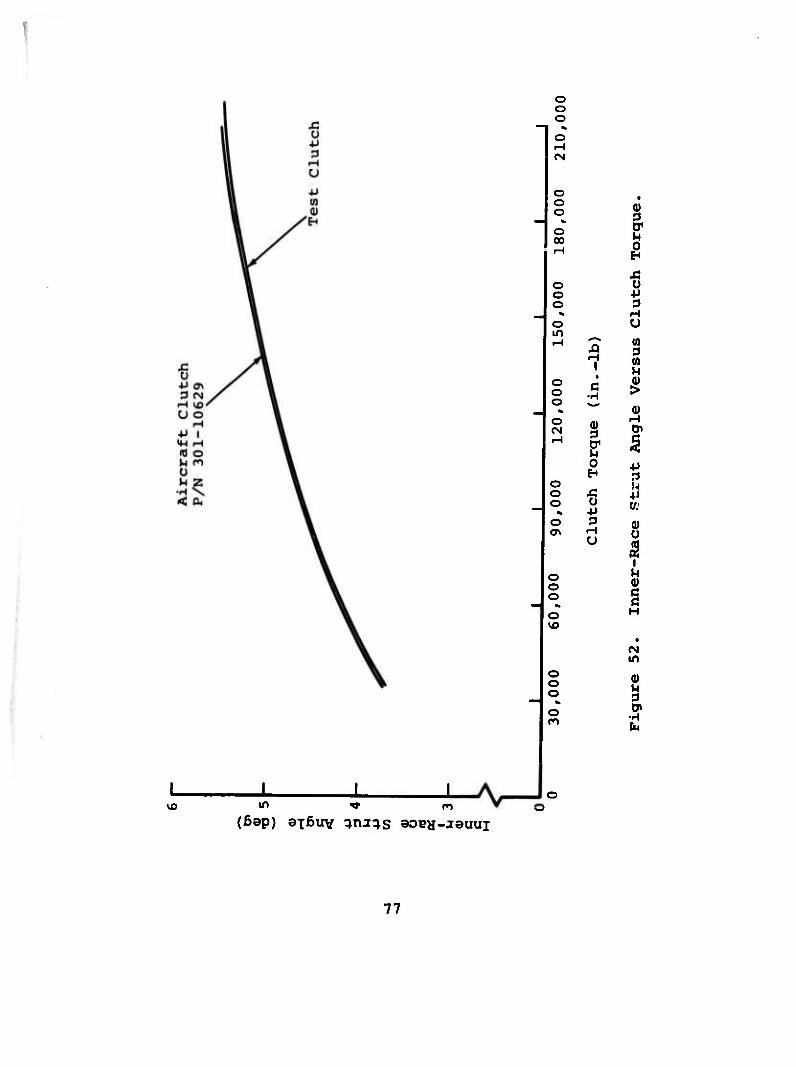
o o o o rH
O O O
O CD
O O O
o in
I I vo in v n
(6ap) axßuv ^ai^s SOBH-JSUUI
0)
&
8
H u iH "^ (0
5 ■ 3 (0 1 M
O o
t
C ■H 1
o * fl)
o CN
ff
2* rH 5
0 +J EH 3
O L o Ä 41 o O w; o 3 0) <T\ rH 0
U
f o o o
H
o H
vo •
in o o o o n
0)
CM
77
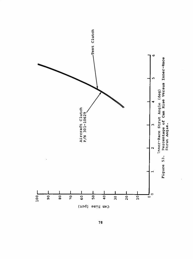
s: ü ■p 3 i-l U
vo
m
< cu
J L J L
n
(N
o o O O o o o o o o <Ti CO 1- vo in T m <N
Jo o
§ C
0> (1)
0)
3 I ■P 3
■P W
0) u (0 « I
(U c c
n in
I ■H CM
0 • 0)
Q) -1 tr oi
■p 3 c 0) p u 3 M )-i 0) P &4 Cß
(^od) asjii uieo
78
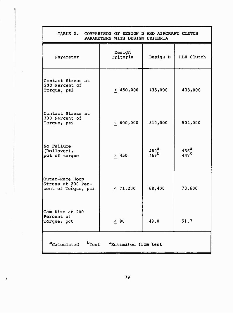
TABLE X. COMPARISON OF DESIGN D AND AIRCRAFT CLUTCH PARAMETERS WITH DESIGN CRITERIA
Parameter Design
Criteria Design D HLH Clutch
Contact Stress at 200 Percent of Torque, psi < 450,000 435,000 433,000
Contact Stress at 300 Percent of Torque, psi < 600,000 510,000 504,000
No Failure (Rollover) , pet of torque > 450
489j 469b
466a
447C
Outer-Race Hoop Stress at 200 Per- cent of Torque, psi <_ 71,200 68,400 73,600
Cam Rise at 200 Percent of Torque, pet _< 80 49.8 51.7
Calculated bTest Estimated fi rom test
79
CONCLUSIONS
The three clutch designs evaluated successfully met all of the technical requirements of the dynamic tests with the aid of alternative parts. The clutch design and manufacturer were therefore selected on the basis of:
• Cost
• Engineering cooperation between vendor and purchaser
The clutch selected as the optimum configuration was manufac- tured by the Borg-Warner Company. It successfully passed all tests and met all design criteria.
The few minor discrepancies found will be eliminated by more stringent manufacturing processes and better quality-control methods.
80

APPENDIX SPRAG-CLUTCH ANALYSIS
The objective of this analysis is to determine the following items as functions of torque: strut angles, contact stresses, race-hoop stresses, and cam rise. In the following paragraphs the pertinent aquations are derived and the method of solution is outlined.
SPRAG GEOMETRY
The basic sprag geometry is shown in Figure 54.
1 NRj ** *^^ ^a
F - Fi Fri TAN Xi 1 f if-^Sk^
fi 71 Fi +* Fr » F0 +♦ Fr„ i u /
'/V- SPRAG
FRi INNER
' RACE
"o
Figure 54. Sprag Geometry.
By definition, h = R0 - R. . By law of cosines,
2 2 2 cos B = (Ri + ri) + (R° " r°) " e
2(Ri + ri)(R0 - r0)
ß = cos 2 2 2
-1 (Ri + ri) + (Ro lV ~ e
2{Ri + riJCRo - r0)
SIN B = e cos (9 + T) Ri + ri
TAN a0 = Ri SIN ß
R„ - r. COS ß O 1
81
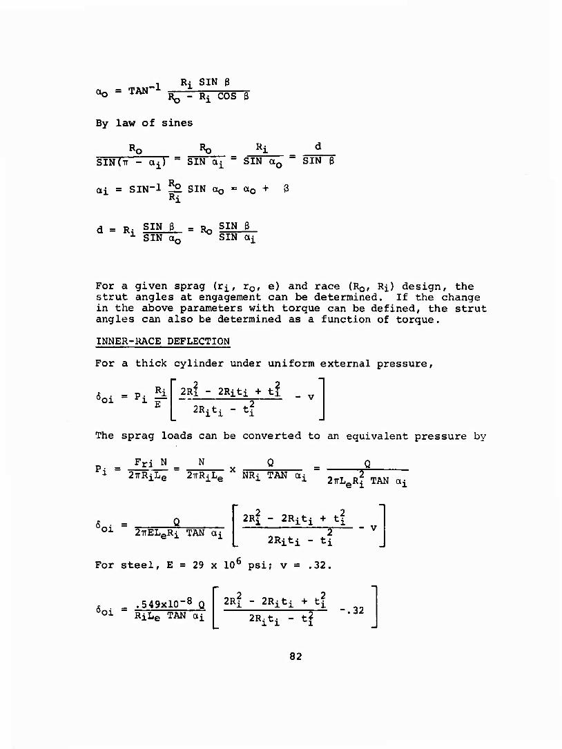
, Ri SIN ß OQ - TAN' ___—g-
By law of sines
Ro Ro «4
SIN(TT - tti) - SIN ÖJ " SIN a0 ■" SIN ß
ai = SIN-1 5° SIN a0 = a0 + ß Ri
d = Ri SIN § = Ro SIN ar
SIN ß SIN a^
For a given sprag (ri, r0, e) and race (R0, Ri) design, the strut angles at engagement can be determined. If the change in the above parameters with torque can be defined, the strut angles can also be determined as a function of torque.
INNER-RACE DEFLECTION
For a thick cylinder under uniform external pressure,
6oi = Pi ^\pi - ^i'l * *! - v
The sprag loads can be converted to an equivalent pressure by
P^ = ri N N 1 ~ 27rRiLe 2TrRiLe
X NRi TAN ai " ^ R2 e-i TAN ai
6 ■ = Q 01 27rELeRi TAN «i
2Ri - 2Riti + tf
2Riti - ti - V
For steel, E = 29 x 10° psi; v = .32.
'oi .549xl0~8 Q RiLe TAN ai
2Ri - 2Riti + tf
2RltI - tl -.32
82
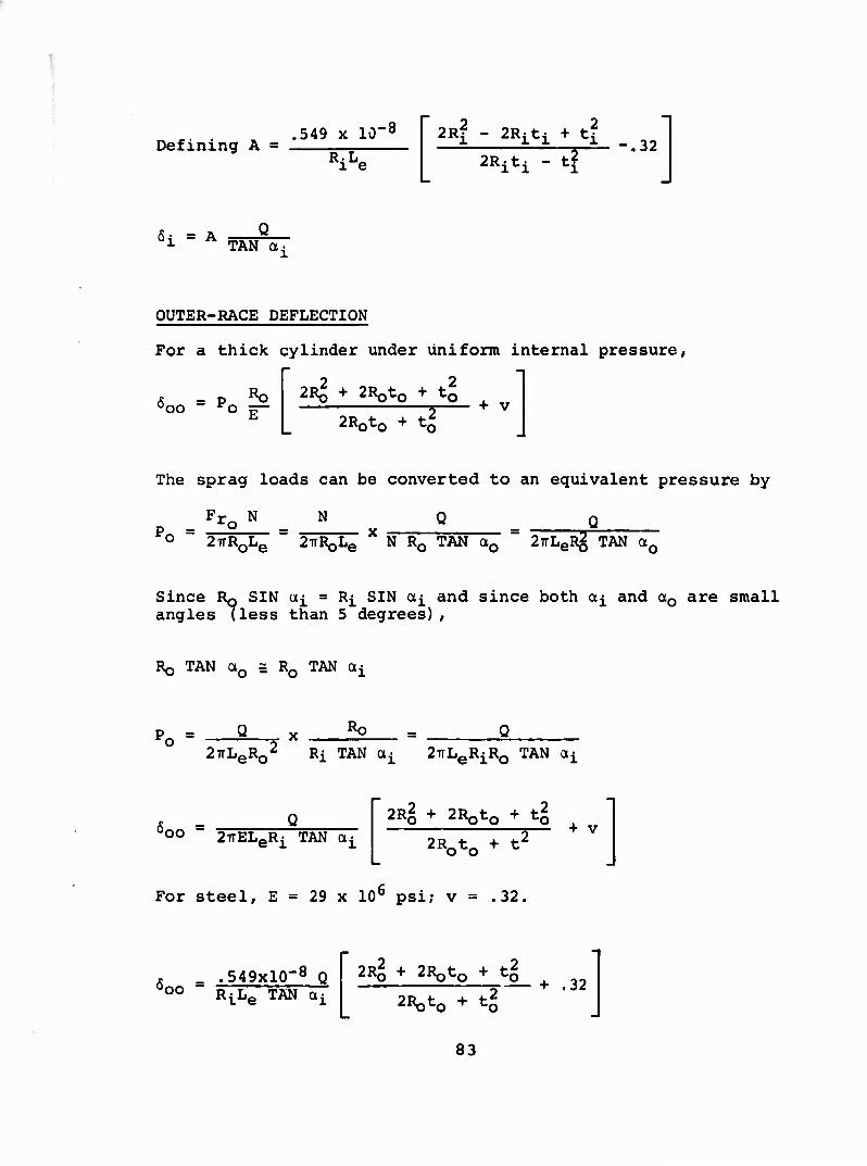
Defining A = .549 x lO-8
We 2R| - 2Riti + tl
2*iH - 4 .32
5- = A g 01 A TAN a,
OUTER-RACE DEFLECTION
For a thick cylinder under uniform internal pressure,
i
T & = P ^ Ooo ro £—
2R2 + ZRotQ + tl + V
2R0t0 + t^,
The sprag loads can be converted to an equivalent pressure by
Fr0 N N 0 Q Po ~ 2TTR0Le " JirR^L^ X N R0 TAN a0 =! 2TrLeR2 TAN a0
Since RQ SIN a^ ■ R^ SIN a^ and since both a^ and a0 are small angles (less than 5 degrees) ,
RQ TAN a0 £ R0 TAN a^
po = 2TrLeR0^ Ri TAN a^^ 2irLeRiR0 TAN a^
00 " 2TTELeRi TAN O^ 2Rg ■» 2R0t0 + tl
2R0t0 + t2 + v
For steel, E = 29 x 106 psi; v = .32.
'oo = .549xl0~8 Q R^IJQ TAN cxi
2*1 + 2R0t0 + tg 2R0t0 + tl
+ .32
83
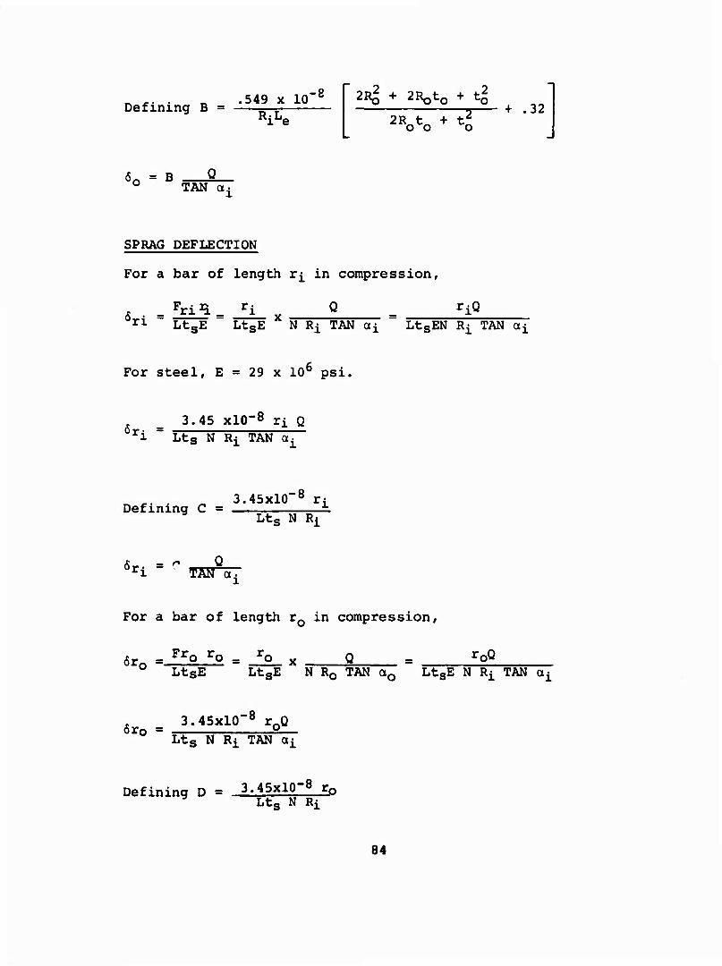
Defining B = .549 x 10
RiLe
-8 2Rg + 2Roto + t*
2Rrtt„ + t? o o o + .32
<S« = B TAN Ot:
SPRAG DEFLECTION
For a bar of length r^ in compression,
= !£i3= Jl- x Q _ riQ rl LtsE LtsE N Ri TAN ai LtsEN Ri TAN ai
For steel, E = 29 x 10b psi.
6r. = 3.45 xlO"8 ri Q
i Lts N Ri TAN QCj
Defining C = 3.45xl0"8 rj
Lts N Ri
6r. = C TAM a.
For a bar of length r0 in compression,
6r0 = FrQ ro = J2_ x r0Q LtsE LtsE N R0 TAN a0 LtsE N Ri TAN ai
m 3.45x10⁻⁸ r0Q Ltg N Ri TAN oti
Defining D = 3.45x10⁻⁸ ro Ltg N Ri
84

6r = D —§ rO TAN OU
SPRAG-RACE CONTACT DEFLECTION
The approach between a steel cylinder and plane is given by
&n = .436x10 -8 P .9
& _ .436X10-8 .9 .436xl0-8
N Ri TAN 0Li
.9
5 .436xl0-8
ci " L.8N.9R.9 i
.9
TAN a,
- .436x10-8 TTS
6„n = .^-^xxu ^ .9 _ .436xl0-8
CO S X r T .8
H .9
N R0 TAN a0
Since Rg SIN a0 = R^ SIN a^ and since both a^ and OLQ are small angles (less than 5 degrees) , R0 TAN a0 = R^ TAN a^.
_ .436xl0~8 CO " L-8N-V TAN on
.9
Defining H = _ .436xl0-8
L.8N.9R.9
6ci = 6co = H TAN ai
85
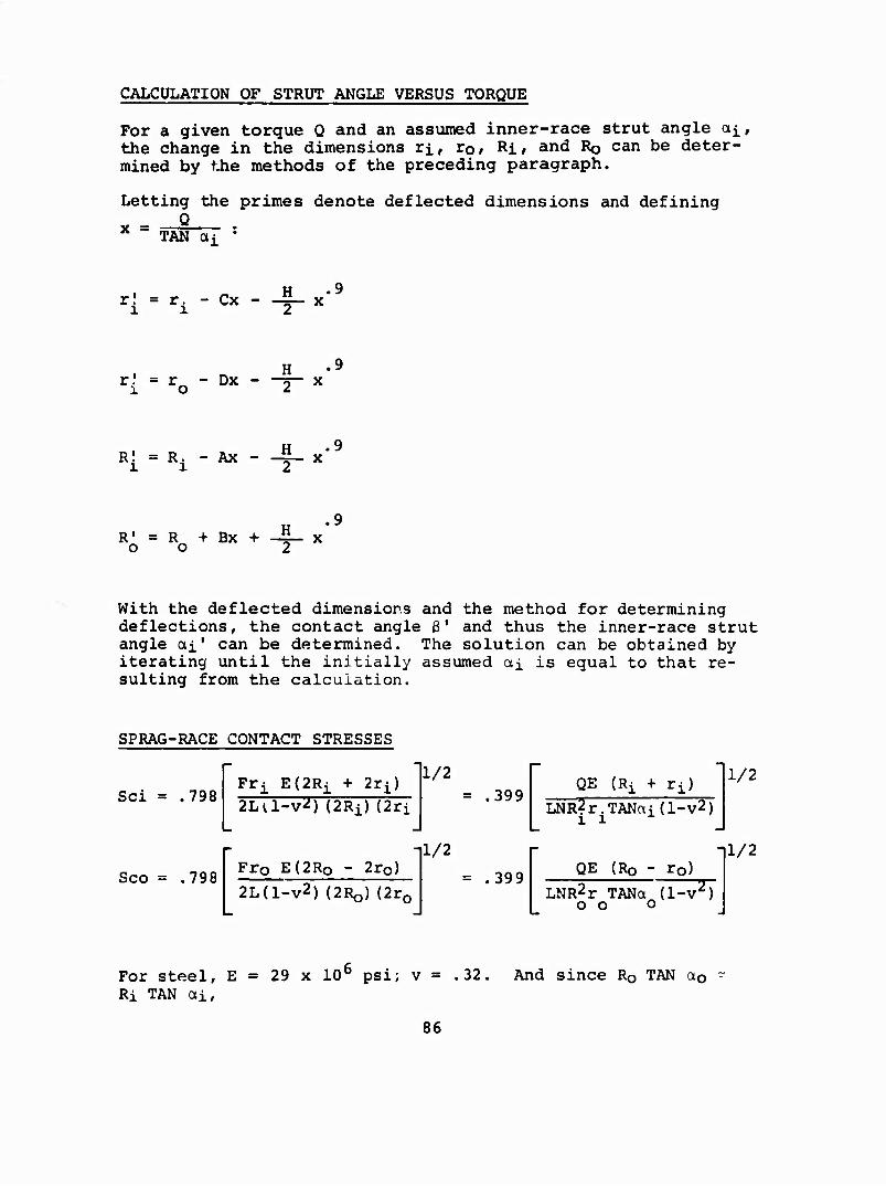
CALCULATION OF STRUT ANGLE VERSUS TORQUE
For a given torque Q and an assumed inner-race strut angle oti, the change in the dimensions rj., rof Ri» and RQ can be deter- mined by the methods of the preceding paragraph.
Letting the primes denote deflected dimensions and defining Q
TAN di *
r! = r. - Cx - 4-*
r! = ro - Dx - H 2 x
R| = Ri - Ax - 4-
R1 = R + Bx O O
+ -¥*
.9
.9
.9
With the deflected dimensions and the method for determining deflections, the contact angle 3' and thus the inner-race strut angle oti' can be determined. The solution can be obtained by iterating until the initially assumed cti is equal to that re- sulting from the calculation.
SPRAG-RACE CONTACT STRESSES
Sei = .798
Sco = .798
Fri E{2Ri + 2ri) 2La-v^) (2Ri) (2ri
Frp E(2Ro - 2ro)
2L(l-v2) URQ) (2r0
1/2
1/2
= .399
= .399
QE (Rj + rj)
LNR^r.TANai(l-v2) ii
1/2
QE (RQ - rp)
LNR2r TANa (l-v^) o o o
11/2
For steel, E Ri TAN oti,
= 29 x 106 psi; v = .32. And since RQ TAN ao
86
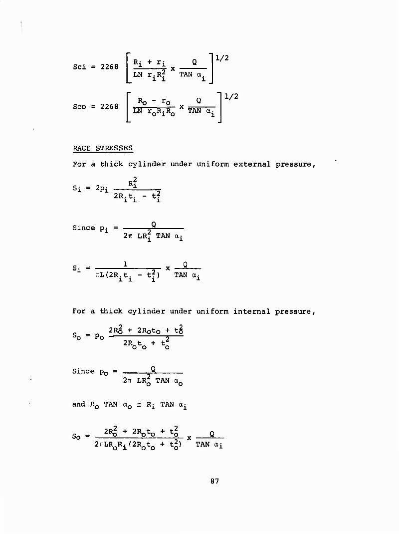
Sei = 2268 Ri + ri Q 5- x LN r.Rf TAN ot.
11 1
1/2
Sco = 2268 Ro - LN TQEJ^RQ TAN ai
1/2
RACE STRESSES
For a thick cylinder under uniform external pressure.
Si = 2pi
2Riti - tf
Since p^ - 5^ 2Tr LR7 TAN a.
Si = 1 TTL(2R.t. - t?) TAN ai
ill l
For a thick cylinder under uniform internal pressure,
2R§ + 2Roto + t§ So = po —: 2— 2R^t„ + t^ 00 o
Since p0 = 2Tr LRQ TAN a0
and R0 TAN a0 = R^ TAN a^
So = 2Rg + 2R0t0 + t| x Q
2TTLR R. (2RÄt + t2) TAN CM 0100 o ■L
87
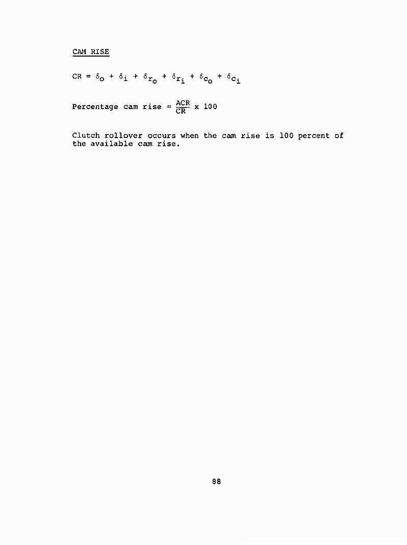
CM RISE
CR = 6n + 6i + 6r + 6r. + 6^ + &r. U X X.Q ij^ l-Q ^2.
ACR Percentage cam rise = ^— x 100 CR
Clutch rollover occurs when the cam rise is 100 percent of the available cam rise.
88

LIST OF SYMBOLS
ACR available cam rise, in.
CR actual cam rise, in.
E modulus of elasticity, psi
e offset between centers of r^ and r0, in.
h sprag height, in.
L sprag contact length, in. (If clutch contains two rows, L is twice the length of each sprag.)
Le effective sprag length (1.05L), in.
N number of sprags per row
Q clutch torque, in.-lb
R race radius, in.
r sprag cam radius, in.
S race circumferential (hoop) stress, psi
Sc sprag-race contact stress, psi
t race thickness, in.
ts sprag thickness, in.
v Poisson's ratio
a strut angle, deg
3 contact angle, deg
Subscripts
i inner race
o outer race
89