distant control of ac relays, contactors, and starters
DESCRIPTION
Data BulletinTRANSCRIPT
Bulletin No. M-379FNovember 1999
Raleigh, NC, USA
Replaces M-379E dated 11/84
Data Bulletin
1© 1984–1999 Schneider Electric All Rights Reserved
When a relay, contactor, or starter is mounted a considerable distance fromthe device controlling it, problems are introduced that are not present whenthe distance is relatively short. The major problems that arise are due to theseries impedance and shunt capacitance of the control wires and their effectupon the proper operation of the relay, contactor, or starter. Because of theinherent characteristics of AC operated magnets, these two problems areimportant at different times and can therefore be treated separately.
Due to the series impedance effect of the control wires in series with thedevice coil, the current drawn through the control wires causes a voltage dropwhich subtracts from the voltage available to the relay, starter, or contactorcoil. If the voltage drop due to this series impedance is large enough, thevoltage available to the device coil may not be sufficient for the device to pickup and seal properly. If the device fails to pick up or seal, and the pickupsignal is maintained, a coil burnout is likely.
The series impedance effect of the control wires is particularly importantwhen inrush current is present in the wires, since this is usually the only timewhen the current is sufficient to cause an appreciable difference between thesource voltage and the voltage available to the device coil. NEMA standardsrequire AC operated magnetic devices to operate satisfactorily at 85% of therated coil voltage. Allowing for a line voltage fluctuation of 10% below therated voltage, the voltage drop caused by the series impedance effect of thecontrol wires should be limited to 5% to insure satisfactory operation of thecircuit.
The tables beginning on page 5 of this bulletin show the maximum distancein feet between the relay, contactor, or starter and the device controlling it,based on a maximum difference of 5% between the source voltage and thevoltage available to the device coil during inrush conditions. This data isbased on 60 Hz voltage sources only.
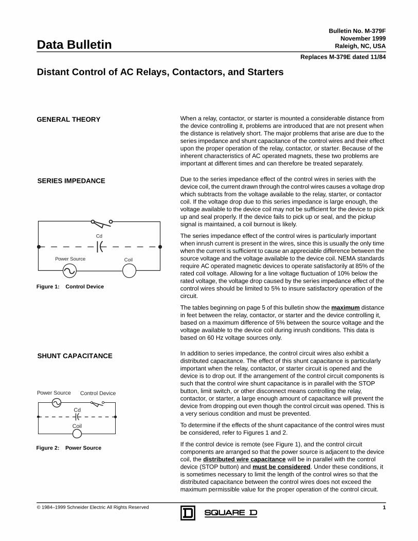
In addition to series impedance, the control circuit wires also exhibit adistributed capacitance. The effect of this shunt capacitance is particularlyimportant when the relay, contactor, or starter circuit is opened and thedevice is to drop out. If the arrangement of the control circuit components issuch that the control wire shunt capacitance is in parallel with the STOPbutton, limit switch, or other disconnect means controlling the relay,contactor, or starter, a large enough amount of capacitance will prevent thedevice from dropping out even though the control circuit was opened. This isa very serious condition and must be prevented.
To determine if the effects of the shunt capacitance of the control wires mustbe considered, refer to Figures 1 and 2.
If the control device is remote (see Figure 1), and the control circuitcomponents are arranged so that the power source is adjacent to the devicecoil, the distributed wire capacitance will be in parallel with the controldevice (STOP button) and must be considered . Under these conditions, itis sometimes necessary to limit the length of the control wires so that thedistributed capacitance between the control wires does not exceed themaximum permissible value for the proper operation of the control circuit.
GENERAL THEORY
SERIES IMPEDANCE
Cd
Power Source Coil
Figure 1: Control Device
SHUNT CAPACITANCE
Cd
Power Source
Coil
Control Device
Figure 2: Power Source
Distant Control of AC Relays, Contactors, and Starters
Distant Control of AC Relays, Contactors and Starters Bulletin No. M-379FData Bulletin November 1999
2 © 1984–1999 Schneider Electric All Rights Reserved
This will shunt the device coil in the energized state even though the controlcircuit is open. (See Figure 2.)
If the power source is adjacent to the control device (STOP button), openingthe control device contact will de-energize the distributed capacitance andthe relay, contactor, or starter coil. The distributed wire capacitance neednot be considered in determining the length of the control wire run, sincethe capacitance does not prevent the STOP button from functioning. In suchcases, the series impedance effect of the control wires is the limiting factor.
In practical applications, the system should not be installed first and thentried out later. Even though the circuit may work properly initially, conditionsmay change due to wear, aging, deteriorating insulation, humidity, or otherfactors, and the relay, contactor, or starter coil being controlled may not pickup or drop out at some critical moment. For this reason, it is important tocalculate the maximum allowable control distance that permits continuedreliable operation.
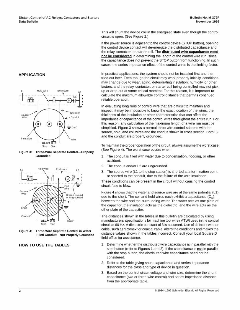
In evaluating long runs of control wire that are difficult to maintain andinspect, it may be impossible to know the exact location of the wires, thethickness of the insulation or other characteristics that can affect theimpedance or capacitance of the control wires throughout the entire run. Forthis reason, any calculation of the maximum length of a wire run must besimplified. Figure 3 shows a normal three-wire control scheme with thesource, hold, and coil wires and the conduit shown in cross section. Both L2and the conduit are properly grounded.
To maintain the proper operation of the circuit, always assume the worst case(See Figure 4). The worst case occurs when:
1. The conduit is filled with water due to condensation, flooding, or otheraccident.
2. The conduit and/or L2 are ungrounded.
3. The source wire (L1 to the stop station) is shorted at a termination point,or shorted to the conduit, due to the failure of the wire insulation.
These conditions can be present in the circuit without causing the controlcircuit fuse to blow.
Figure 4 shows that the water and source wire are at the same potential (L1)due to the short. The coil and hold wires each exhibit a capacitance (Cw)between the wire and the surrounding water. The water acts as one plate ofthe capacitor; the insulation acts as the dielectric; and the wire acts as theother plate of the capacitor.
The distances shown in the tables in this bulletin are calculated by usingmanufacturers' specifications for machine tool wire (MTW) used in the controlcircuit at 60 Hz. A dielectric constant of 8 is assumed. Use of different wire orcable, such as “Romex” or coaxial cable, alters the conditions and makes thedistance values shown in the tables incorrect. Consult your local Square Dfield office for assistance.
1. Determine whether the distributed wire capacitance is in parallel with thestop button (refer to Figures 1 and 2). If the capacitance is not in parallelwith the stop button, the distributed wire capacitance need not beconsidered.
2. Refer to the table giving shunt capacitance and series impedancedistances for the class and type of device in question.
3. Based on the control circuit voltage and wire size, determine the shuntcapacitance (two or three-wire control) and series impedance distancefrom the appropriate table.
APPLICATION
L1 Hold Wire Enclosure L2
Fuse
SourceWire
Coil Wire
Conduit
GND
WireInsulation
Stop Start
OLMM
Figure 3: Three-Wire Separate Control —ProperlyGrounded
L1 Hold Wire Enclosure L2
Fuse
SourceWire
CoilWire
Conduit
Water
Short
Stop Start
OLMM
Broken Groundor Ungrounded
Cw
Figure 4: Three-Wire Separate Control in WaterFilled Conduit —Not Properly Grounded
HOW TO USE THE TABLES
Bulletin No. M-379F Distant Control of AC Relays, Contactors and StartersNovember 1999 Data Bulletin
3© 1984–1999 Schneider Electric All Rights Reserved
NOTE: All tables refer to American Wire Gauge (AWG) copper wire.
4. When the shunt capacitance distance is greater than the seriesimpedance distance, the series impedance distance is the limiting value.(In this case, to avoid confusion, the shunt capacitance value does notappear in the table and reference to a footnote is made.)
5. When the shunt capacitance distance is less than the series impedancedistance, the shunt capacitance distance is the limiting value.
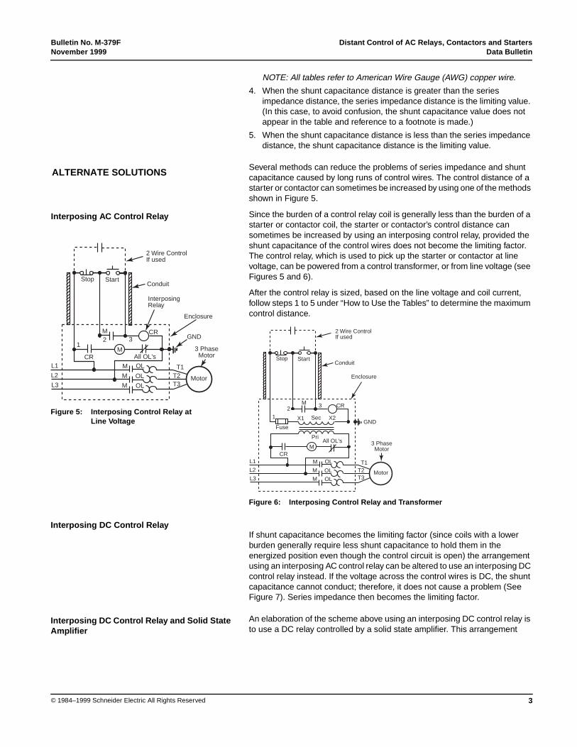
Several methods can reduce the problems of series impedance and shuntcapacitance caused by long runs of control wires. The control distance of astarter or contactor can sometimes be increased by using one of the methodsshown in Figure 5.
Since the burden of a control relay coil is generally less than the burden of astarter or contactor coil, the starter or contactor’s control distance cansometimes be increased by using an interposing control relay, provided theshunt capacitance of the control wires does not become the limiting factor.The control relay, which is used to pick up the starter or contactor at linevoltage, can be powered from a control transformer, or from line voltage (seeFigures 5 and 6).
After the control relay is sized, based on the line voltage and coil current,follow steps 1 to 5 under “How to Use the Tables” to determine the maximumcontrol distance.
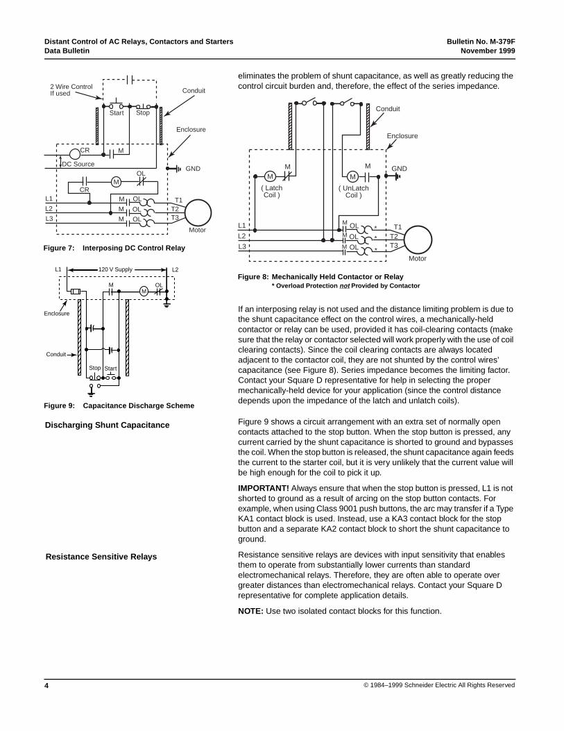
If shunt capacitance becomes the limiting factor (since coils with a lowerburden generally require less shunt capacitance to hold them in theenergized position even though the control circuit is open) the arrangementusing an interposing AC control relay can be altered to use an interposing DCcontrol relay instead. If the voltage across the control wires is DC, the shuntcapacitance cannot conduct; therefore, it does not cause a problem (SeeFigure 7). Series impedance then becomes the limiting factor.
An elaboration of the scheme above using an interposing DC control relay isto use a DC relay controlled by a solid state amplifier. This arrangement
ALTERNATE SOLUTIONS
Interposing AC Control Relay
L1
L2
L3
1
CR
M2 3
M
M
M
M
OL
OL
OL
All OL's
CR
Motor
T1T2T3
GND
3 PhaseMotor
Enclosure
InterposingRelay
ConduitStop Start
2 Wire ControlIf used
Figure 5: Interposing Control Relay atLine Voltage
Interposing DC Control Relay
L1
L2
L3
1
M2 3
M
M
M
M
OL
OL
OL
All OL's
CR
Motor
T1T2T3
GND
3 PhaseMotor
Enclosure
ConduitStop Start
2 Wire ControlIf used
Fuse
CR
X1 X2Sec
Pri
Figure 6: Interposing Control Relay and Transformer
Interposing DC Control Relay and Solid StateAmplifier
Distant Control of AC Relays, Contactors and Starters Bulletin No. M-379FData Bulletin November 1999
4 © 1984–1999 Schneider Electric All Rights Reserved
eliminates the problem of shunt capacitance, as well as greatly reducing thecontrol circuit burden and, therefore, the effect of the series impedance.
If an interposing relay is not used and the distance limiting problem is due tothe shunt capacitance effect on the control wires, a mechanically-heldcontactor or relay can be used, provided it has coil-clearing contacts (makesure that the relay or contactor selected will work properly with the use of coilclearing contacts). Since the coil clearing contacts are always locatedadjacent to the contactor coil, they are not shunted by the control wires’capacitance (see Figure 8). Series impedance becomes the limiting factor.Contact your Square D representative for help in selecting the propermechanically-held device for your application (since the control distancedepends upon the impedance of the latch and unlatch coils).
Figure 9 shows a circuit arrangement with an extra set of normally opencontacts attached to the stop button. When the stop button is pressed, anycurrent carried by the shunt capacitance is shorted to ground and bypassesthe coil. When the stop button is released, the shunt capacitance again feedsthe current to the starter coil, but it is very unlikely that the current value willbe high enough for the coil to pick it up.
IMPORTANT! Always ensure that when the stop button is pressed, L1 is notshorted to ground as a result of arcing on the stop button contacts. Forexample, when using Class 9001 push buttons, the arc may transfer if a TypeKA1 contact block is used. Instead, use a KA3 contact block for the stopbutton and a separate KA2 contact block to short the shunt capacitance toground.
Resistance sensitive relays are devices with input sensitivity that enablesthem to operate from substantially lower currents than standardelectromechanical relays. Therefore, they are often able to operate overgreater distances than electromechanical relays. Contact your Square Drepresentative for complete application details.
NOTE: Use two isolated contact blocks for this function.
L1
L2
L3
CR
DC Source
M
M
M
M
OL
OL
OL
OL
CR
T1T2T3
GND
Motor
Enclosure
Conduit
StopStart
2 Wire ControlIf used
M
Figure 7: Interposing DC Control Relay
L1
L2
L3
( LatchCoil )
M
M
M
M
OL
OL
OL
T1T2T3
GND
Motor
Enclosure
Conduit
M
MM
**
*
( UnLatchCoil )
Figure 8: Mechanically Held Contactor or Relay* Overload Protection not Provided by Contactor
Discharging Shunt Capacitance
MM
OL
Stop Start
120 V Supply
Enclosure
Conduit
L1 L2
Figure 9: Capacitance Discharge Scheme
Resistance Sensitive Relays
Bulletin No. M-379F Distant Control of AC Relays, Contactors and StartersNovember 1999 Data Bulletin
5© 1984–1999 Schneider Electric All Rights Reserved
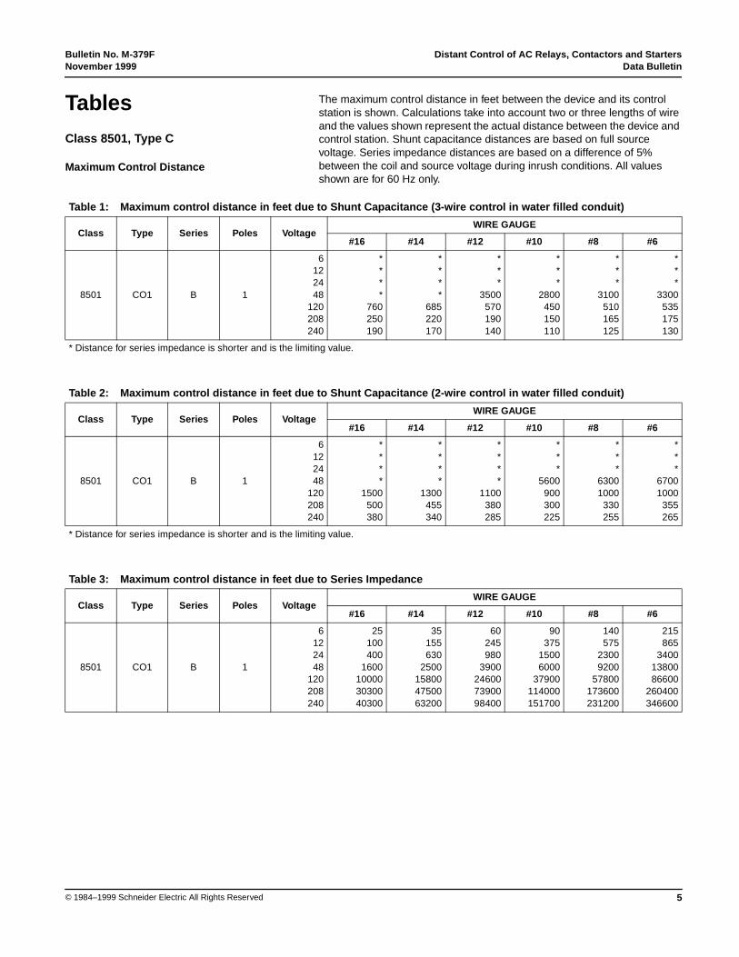
The maximum control distance in feet between the device and its controlstation is shown. Calculations take into account two or three lengths of wireand the values shown represent the actual distance between the device andcontrol station. Shunt capacitance distances are based on full sourcevoltage. Series impedance distances are based on a difference of 5%between the coil and source voltage during inrush conditions. All valuesshown are for 60 Hz only.
TablesClass 8501, Type C
Maximum Control Distance
Table 1: Maximum control distance in feet due to Shunt Capacitance (3-wire control in water filled conduit)
Class Type Series Poles VoltageWIRE GAUGE
#16 #14 #12 #10 #8 #6
8501 CO1 B 1
6122448
120208240
****
760250190
****
685220170
***
3500570190140
***
2800450150110
***
3100510165125
***
3300535175130
* Distance for series impedance is shorter and is the limiting value.
Table 2: Maximum control distance in feet due to Shunt Capacitance (2-wire control in water filled conduit)
Class Type Series Poles VoltageWIRE GAUGE
#16 #14 #12 #10 #8 #6
8501 CO1 B 1
6122448
120208240
****
1500500380
****
1300455340
****
1100380285
***
5600900300225
***
63001000
330255
***
67001000
355265
* Distance for series impedance is shorter and is the limiting value.
Table 3: Maximum control distance in feet due to Series Impedance
Class Type Series Poles VoltageWIRE GAUGE
#16 #14 #12 #10 #8 #6
8501 CO1 B 1
6122448
120208240
25100400
1600100003030040300
35155630
2500158004750063200
60245980
3900246007390098400
90375
15006000
37900114000151700
140575
23009200
57800173600231200
215865
34001380086600
260400346600
Distant Control of AC Relays, Contactors and Starters Bulletin No. M-379FData Bulletin November 1999
6 © 1984–1999 Schneider Electric All Rights Reserved
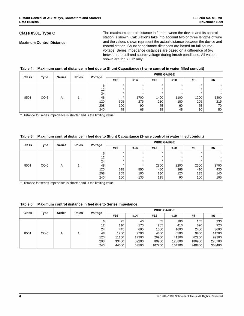
The maximum control distance in feet between the device and its controlstation is shown. Calculations take into account two or three lengths of wireand the values shown represent the actual distance between the device andcontrol station. Shunt capacitance distances are based on full sourcevoltage. Series impedance distances are based on a difference of 5%between the coil and source voltage during inrush conditions. All valuesshown are for 60 Hz only.
Class 8501, Type C
Maximum Control Distance
Table 4: Maximum control distance in feet due to Shunt Capacitance (3-wire control in water filled conduit)
Class Type Series Poles VoltageWIRE GAUGE
#16 #14 #12 #10 #8 #6
8501 CO-5 A 1
6122448
120208240
****
305100
75
***
1700275
9065
***
1400230
7555
***
1100180
6045
***
1200205
6550
***
1300215
7050
* Distance for series impedance is shorter and is the limiting value.
Table 5: Maximum control distance in feet due to Shunt Capacitance (2-wire control in water filled conduit)
Class Type Series Poles VoltageWIRE GAUGE
#16 #14 #12 #10 #8 #6
8501 CO-5 A 1
6122448
120208240
****
615205150
****
550180135
***
2800460150115
***
2200365120
90
***
2500410135100
***
2700430140105
* Distance for series impedance is shorter and is the limiting value.
Table 6: Maximum control distance in feet due to Series Impedance
Class Type Series Poles VoltageWIRE GAUGE
#16 #14 #12 #10 #8 #6
8501 CO-5 A 1
6122448
120208240
25110445
1700111003340044500
40170695
2700173005220069500
65265
10004300
2690080900
107700
100410
16006500
41200123800164900
155620
24009900
62200186900248800
230920
36001470092100
276700368400

Bulletin No. M-379F Distant Control of AC Relays, Contactors and StartersNovember 1999 Data Bulletin
7© 1984–1999 Schneider Electric All Rights Reserved
The maximum control distance in feet between the device and its controlstation is shown. Calculations take into account two or three lengths of wireand the values shown represent the actual distance between the device andcontrol station. Shunt capacitance distances are based on full sourcevoltage. Series impedance distances are based on a difference of 5%between the coil and source voltage during inrush conditions. All valuesshown are for 60 Hz only.
Class 8501, Type C
Maximum Control Distance
Table 7: Maximum control distance in feet due to Shunt Capacitance (3-wire control in water filled conduit)
Class Type Series Poles VoltageWIRE GAUGE
#16 #14 #12 #10 #8 #6
8501 CO11 A 1
6122448
120208240
***
1100175
5540
***
1 000160
5040
***
840130
4030
***
665105
3525
***
750120
3530
**
3100790125
4030
* Distance for series impedance is shorter and is the limiting value.
Table 8: Maximum control distance in feet due to Shunt Capacitance (2-wire control in water filled conduit)
Class Type Series Poles VoltageWIRE GAUGE
#16 #14 #12 #10 #8 #6
8501 CO11 A 1
6122448
120208240
****
355115
85
***
2000320105
80
***
1600265
8565
***
1300210
7050
***
1500240
7560
***
1500250
8060
* Distance for series impedance is shorter and is the limiting value.
Table 9: Maximum control distance in feet due to Series Impedance
Class Type Series Poles VoltageWIRE GAUGE
#16 #14 #12 #10 #8 #6
8501 CO11 A 1
6122448
120208240
25115465
1800117003510046800
45180730
2900182005490073100
70280
11004500
2830085100
113300
105430
17006900
43400130500173700
160655
26001050065600
197200262500
240970
38001550097400
292600389600
Distant Control of AC Relays, Contactors and Starters Bulletin No. M-379FData Bulletin November 1999
8 © 1984–1999 Schneider Electric All Rights Reserved
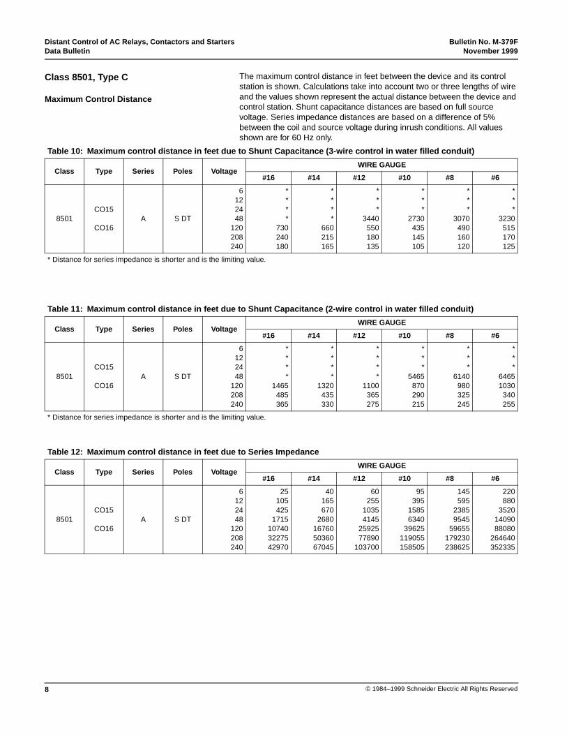
The maximum control distance in feet between the device and its controlstation is shown. Calculations take into account two or three lengths of wireand the values shown represent the actual distance between the device andcontrol station. Shunt capacitance distances are based on full sourcevoltage. Series impedance distances are based on a difference of 5%between the coil and source voltage during inrush conditions. All valuesshown are for 60 Hz only.
Class 8501, Type C
Maximum Control Distance
Table 10: Maximum control distance in feet due to Shunt Capacitance (3-wire control in water filled conduit)
Class Type Series Poles VoltageWIRE GAUGE
#16 #14 #12 #10 #8 #6
8501CO15
CO16A S DT
6122448
120208240
****
730240180
****
660215165
***
3440550180135
***
2730435145105
***
3070490160120
***
3230515170125
* Distance for series impedance is shorter and is the limiting value.
Table 11: Maximum control distance in feet due to Shunt Capacitance (2-wire control in water filled conduit)
Class Type Series Poles VoltageWIRE GAUGE
#16 #14 #12 #10 #8 #6
8501CO15
CO16A S DT
6122448
120208240
****
1465485365
****
1320435330
****
1100365275
***
5465870290215
***
6140980325245
***
64651030
340255
* Distance for series impedance is shorter and is the limiting value.
Table 12: Maximum control distance in feet due to Series Impedance
Class Type Series Poles VoltageWIRE GAUGE
#16 #14 #12 #10 #8 #6
8501CO15
CO16A S DT
6122448
120208240
25105425
1715107403227542970
40165670
2680167605036067045
60255
10354145
2592577890
103700
95395
15856340
39625119055158505
145595
23859545
59655179230238625
220880
35201409088080
264640352335
Bulletin No. M-379F Distant Control of AC Relays, Contactors and StartersNovember 1999 Data Bulletin
9© 1984–1999 Schneider Electric All Rights Reserved
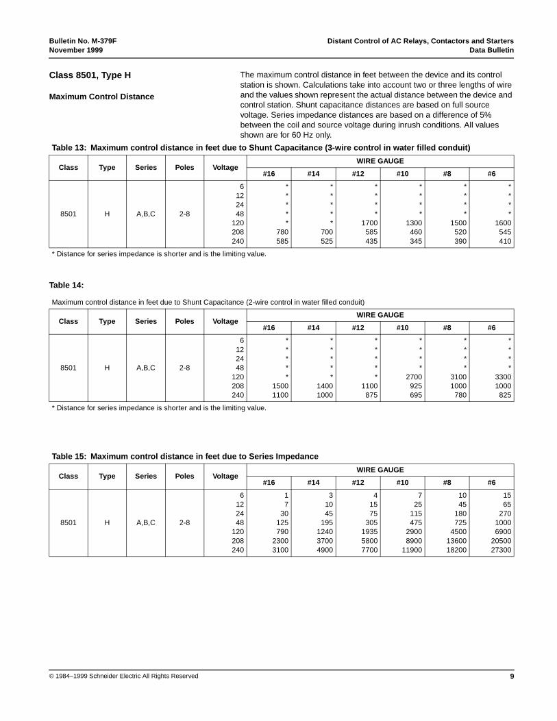
The maximum control distance in feet between the device and its controlstation is shown. Calculations take into account two or three lengths of wireand the values shown represent the actual distance between the device andcontrol station. Shunt capacitance distances are based on full sourcevoltage. Series impedance distances are based on a difference of 5%between the coil and source voltage during inrush conditions. All valuesshown are for 60 Hz only.
Class 8501, Type H
Maximum Control Distance
Table 14:
Table 13: Maximum control distance in feet due to Shunt Capacitance (3-wire control in water filled conduit)
Class Type Series Poles VoltageWIRE GAUGE
#16 #14 #12 #10 #8 #6
8501 H A,B,C 2-8
6122448
120208240
*****
780585
*****
700525
****
1700585435
****
1300460345
****
1500520390
****
1600545410
* Distance for series impedance is shorter and is the limiting value.
Maximum control distance in feet due to Shunt Capacitance (2-wire control in water filled conduit)
Class Type Series Poles VoltageWIRE GAUGE
#16 #14 #12 #10 #8 #6
8501 H A,B,C 2-8
6122448
120208240
*****
15001100
*****
14001000
*****
1100875
****
2700925695
****
31001000
780
****
33001000
825
* Distance for series impedance is shorter and is the limiting value.
Table 15: Maximum control distance in feet due to Series Impedance
Class Type Series Poles VoltageWIRE GAUGE
#16 #14 #12 #10 #8 #6
8501 H A,B,C 2-8
6122448
120208240
17
30125790
23003100
31045
195124037004900
41575
305193558007700
725
115475
29008900
11900
1045
180725
45001360018200
1565
27010006900
2050027300
Distant Control of AC Relays, Contactors and Starters Bulletin No. M-379FData Bulletin November 1999
10 © 1984–1999 Schneider Electric All Rights Reserved
The maximum control distance in feet between the device and its controlstation is shown. Calculations take into account two or three lengths of wireand the values shown represent the actual distance between the device andcontrol station. Shunt capacitance distances are based on full sourcevoltage. Series impedance distances are based on a difference of 5%between the coil and source voltage during inrush conditions. All valuesshown are for 60 Hz only.
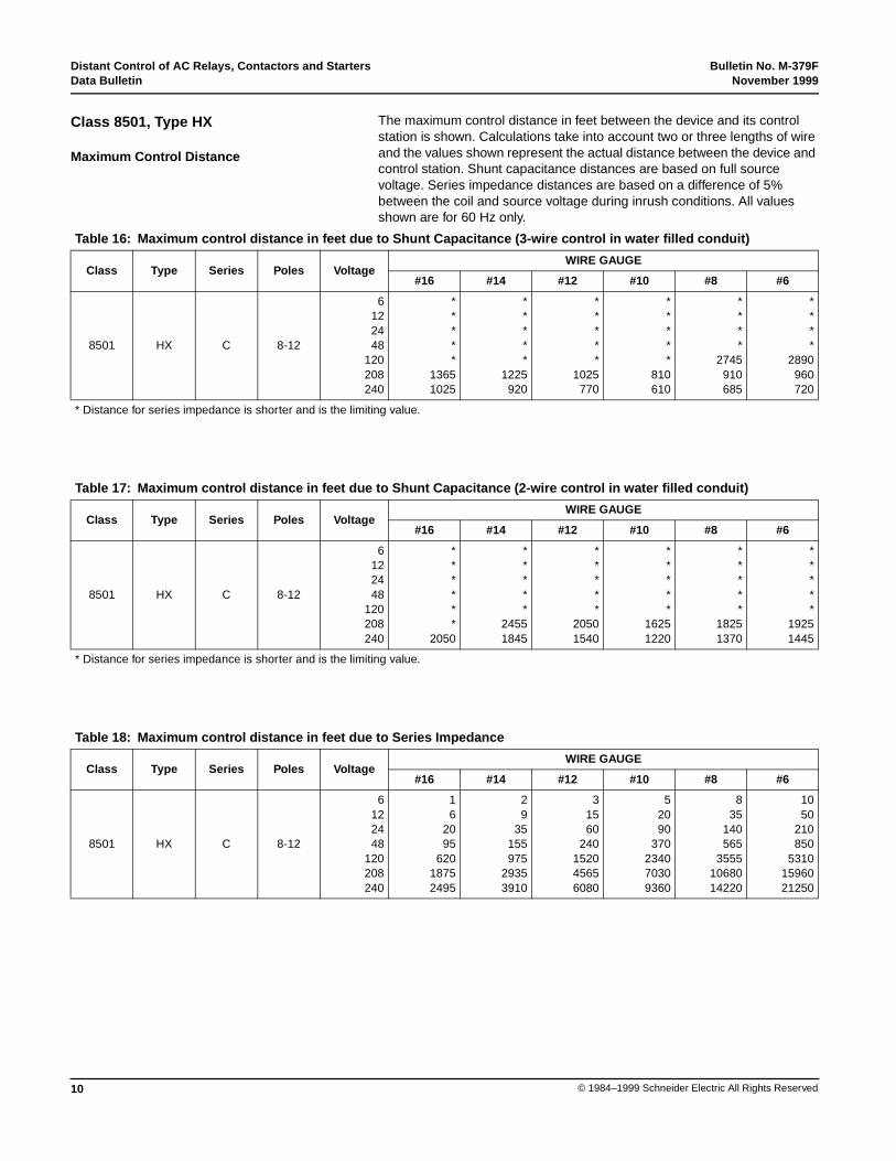
Class 8501, Type HX
Maximum Control Distance
Table 16: Maximum control distance in feet due to Shunt Capacitance (3-wire control in water filled conduit)
Class Type Series Poles VoltageWIRE GAUGE
#16 #14 #12 #10 #8 #6
8501 HX C 8-12
6122448
120208240
*****
13651025
*****
1225920
*****
1025770
*****
810610
****
2745910685
****
2890960720
* Distance for series impedance is shorter and is the limiting value.
Table 17: Maximum control distance in feet due to Shunt Capacitance (2-wire control in water filled conduit)
Class Type Series Poles VoltageWIRE GAUGE
#16 #14 #12 #10 #8 #6
8501 HX C 8-12
6122448
120208240
******
2050
*****
24551845
*****
20501540
*****
16251220
*****
18251370
*****
19251445
* Distance for series impedance is shorter and is the limiting value.
Table 18: Maximum control distance in feet due to Series Impedance
Class Type Series Poles VoltageWIRE GAUGE
#16 #14 #12 #10 #8 #6
8501 HX C 8-12
6122448
120208240
16
2095
62018752495
29
35155975
29353910
31560
240152045656080
52090
370234070309360
835
140565
35551068014220
1050
210850
53101596021250
Bulletin No. M-379F Distant Control of AC Relays, Contactors and StartersNovember 1999 Data Bulletin
11© 1984–1999 Schneider Electric All Rights Reserved
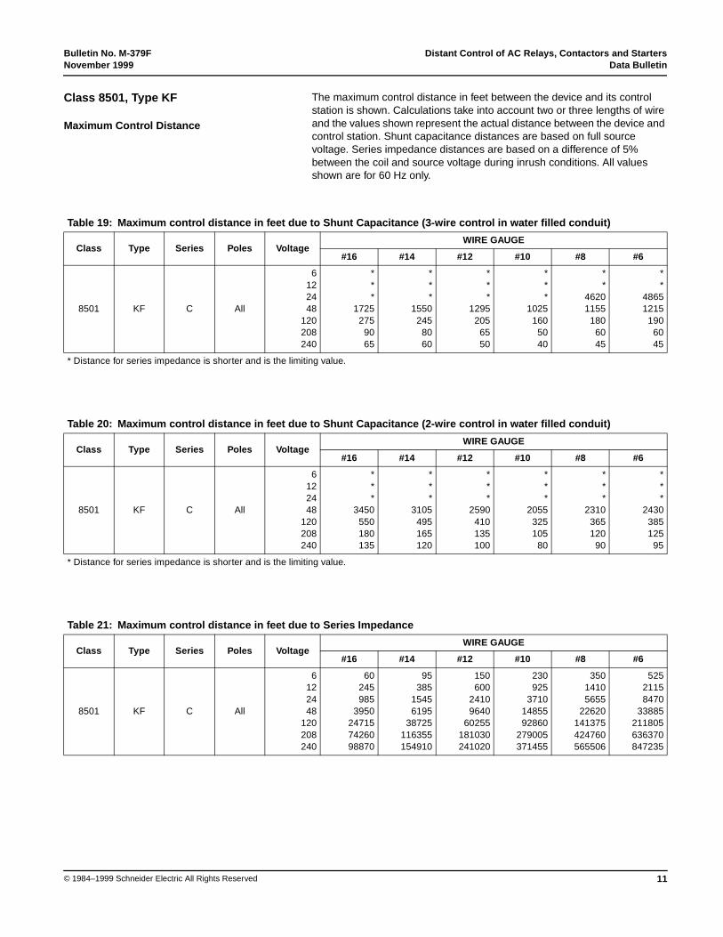
The maximum control distance in feet between the device and its controlstation is shown. Calculations take into account two or three lengths of wireand the values shown represent the actual distance between the device andcontrol station. Shunt capacitance distances are based on full sourcevoltage. Series impedance distances are based on a difference of 5%between the coil and source voltage during inrush conditions. All valuesshown are for 60 Hz only.
Class 8501, Type KF
Maximum Control Distance
Table 19: Maximum control distance in feet due to Shunt Capacitance (3-wire control in water filled conduit)
Class Type Series Poles VoltageWIRE GAUGE
#16 #14 #12 #10 #8 #6
8501 KF C All
6122448
120208240
***
1725275
9065
***
1550245
8060
***
1295205
6550
***
1025160
5040
**
46201155
1806045
**
48651215
1906045
* Distance for series impedance is shorter and is the limiting value.
Table 20: Maximum control distance in feet due to Shunt Capacitance (2-wire control in water filled conduit)
Class Type Series Poles VoltageWIRE GAUGE
#16 #14 #12 #10 #8 #6
8501 KF C All
6122448
120208240
***
3450550180135
***
3105495165120
***
2590410135100
***
2055325105
80
***
2310365120
90
***
2430385125
95
* Distance for series impedance is shorter and is the limiting value.
Table 21: Maximum control distance in feet due to Series Impedance
Class Type Series Poles VoltageWIRE GAUGE
#16 #14 #12 #10 #8 #6
8501 KF C All
6122448
120208240
60245985
3950247157426098870
95385
15456195
38725116355154910
150600
24109640
60255181030241020
230925
37101485592860
279005371455
35014105655
22620141375424760565506
52521158470
33885211805636370847235
Distant Control of AC Relays, Contactors and Starters Bulletin No. M-379FData Bulletin November 1999
12 © 1984–1999 Schneider Electric All Rights Reserved
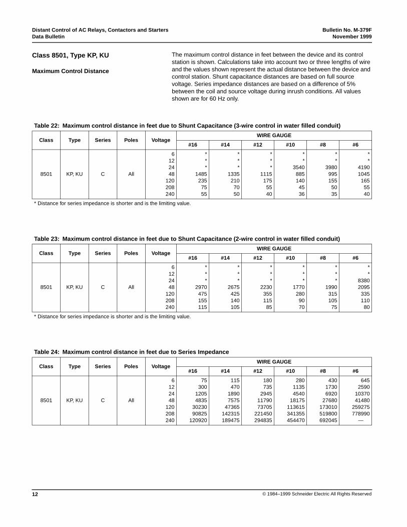
The maximum control distance in feet between the device and its controlstation is shown. Calculations take into account two or three lengths of wireand the values shown represent the actual distance between the device andcontrol station. Shunt capacitance distances are based on full sourcevoltage. Series impedance distances are based on a difference of 5%between the coil and source voltage during inrush conditions. All valuesshown are for 60 Hz only.
Class 8501, Type KP, KU
Maximum Control Distance
Table 22: Maximum control distance in feet due to Shunt Capacitance (3-wire control in water filled conduit)
Class Type Series Poles VoltageWIRE GAUGE
#16 #14 #12 #10 #8 #6
8501 KP, KU C All
6122448
120208240
***
1485235
7555
***
1335210
7050
***
1115175
5540
**
3540885140
4536
**
3980995155
5035
**
41901045
1655540
* Distance for series impedance is shorter and is the limiting value.
Table 23: Maximum control distance in feet due to Shunt Capacitance (2-wire control in water filled conduit)
Class Type Series Poles VoltageWIRE GAUGE
#16 #14 #12 #10 #8 #6
8501 KP, KU C All
6122448
120208240
***
2970475155115
***
2675425140105
***
2230355115
85
***
1770280
9070
***
1990315105
75
**
83802095
335110
80
* Distance for series impedance is shorter and is the limiting value.
Table 24: Maximum control distance in feet due to Series Impedance
Class Type Series Poles VoltageWIRE GAUGE
#16 #14 #12 #10 #8 #6
8501 KP, KU C All
6122448
120208240
75300
12054835
3023090825
120920
115470
18907575
47365142315189475
180735
29451179073705
221450294835
28011354540
18175113615341355454470
43017306920
27680173010519800692045
6452590
1037041480
259275778990
—

Bulletin No. M-379F Distant Control of AC Relays, Contactors and StartersNovember 1999 Data Bulletin
13© 1984–1999 Schneider Electric All Rights Reserved
The maximum control distance in feet between the device and its controlstation is shown. Calculations take into account two or three lengths of wireand the values shown represent the actual distance between the device andcontrol station. Shunt capacitance distances are based on full sourcevoltage. Series impedance distances are based on a difference of 5%between the coil and source voltage during inrush conditions. All valuesshown are for 60 Hz only.
NOTE: Distances shown below apply only to those Type L relays utilizing the31111-400 series coils.
Class 8501, Type LO
Maximum Control Distance
Table 25: Maximum control distance in feet due to Shunt Capacitance (3-wire control in water filled conduit)
Class Type Series Poles VoltageWIRE GAUGE
#16 #14 #12 #10 #8 #6
8501 LO A 2–8
6122448
120208240
*****
670500
*****
600450
****
1510500375
****
1200400300
****
1350445335
****
1420470355
* Distance for series impedance is shorter and is the limiting value.
Table 26: Maximum control distance in feet due to Shunt Capacitance (2-wire control in water filled conduit)
Class Type Series Poles VoltageWIRE GAUGE
#16 #14 #12 #10 #8 #6
8501 LO A 2–8
6122448
120208240
*****
13401005
*****
1250905
*****
1005755
****
2400800600
****
2700895675
****
2840945710
* Distance for series impedance is shorter and is the limiting value..
Table 27: Maximum control distance in feet due to Series Impedance
Class Type Series Poles VoltageWIRE GAUGE
#16 #14 #12 #10 #8 #6
8501 LO A 2–8
6122448
120208240
21040
170106532054265
41565
265167050256695
625
100415
26057835
10430
1040
160640
40251210016110
1560
245980
61451847024595
2090
36514759240
2777036975
Distant Control of AC Relays, Contactors and Starters Bulletin No. M-379FData Bulletin November 1999
14 © 1984–1999 Schneider Electric All Rights Reserved
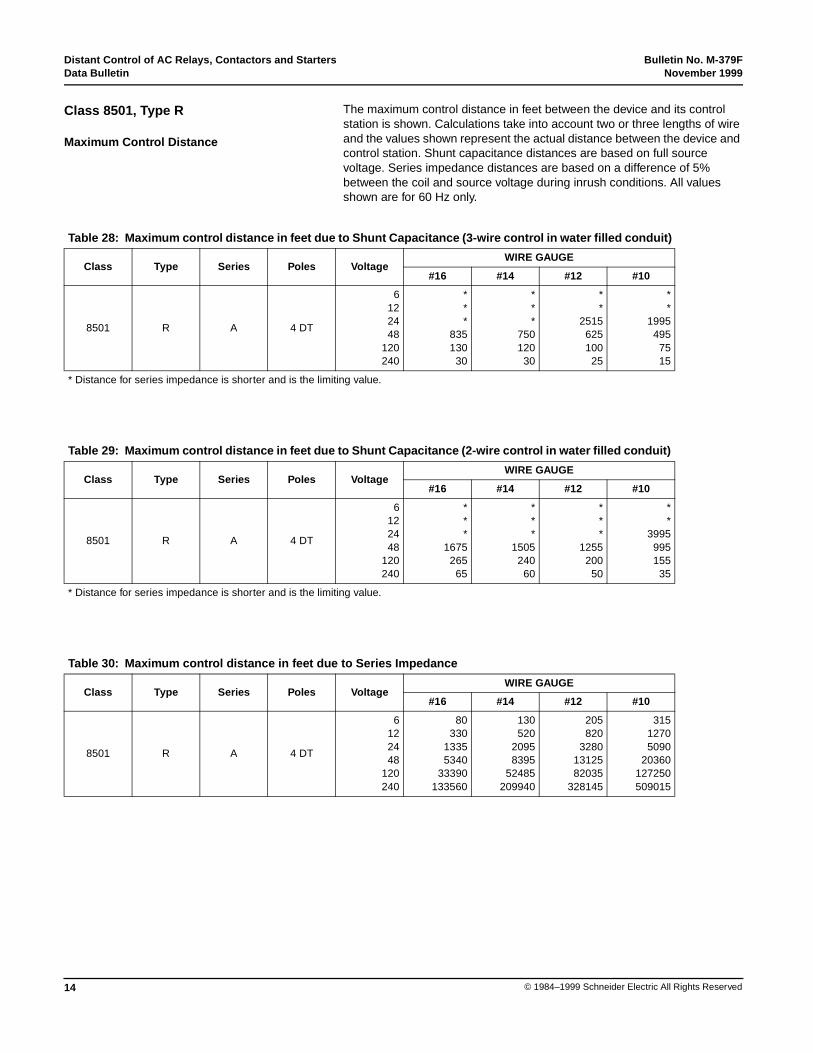
The maximum control distance in feet between the device and its controlstation is shown. Calculations take into account two or three lengths of wireand the values shown represent the actual distance between the device andcontrol station. Shunt capacitance distances are based on full sourcevoltage. Series impedance distances are based on a difference of 5%between the coil and source voltage during inrush conditions. All valuesshown are for 60 Hz only.
Class 8501, Type R
Maximum Control Distance
Table 28: Maximum control distance in feet due to Shunt Capacitance (3-wire control in water filled conduit)
Class Type Series Poles VoltageWIRE GAUGE
#16 #14 #12 #10
8501 R A 4 DT
6122448
120240
***
835130
30
***
750120
30
**
2515625100
25
**
1995495
7515
* Distance for series impedance is shorter and is the limiting value.
Table 29: Maximum control distance in feet due to Shunt Capacitance (2-wire control in water filled conduit)
Class Type Series Poles VoltageWIRE GAUGE
#16 #14 #12 #10
8501 R A 4 DT
6122448
120240
***
1675265
65
***
1505240
60
***
1255200
50
**
3995995155
35
* Distance for series impedance is shorter and is the limiting value.
Table 30: Maximum control distance in feet due to Series Impedance
Class Type Series Poles VoltageWIRE GAUGE
#16 #14 #12 #10
8501 R A 4 DT
6122448
120240
80330
13355340
33390133560
130520
20958395
52485209940
205820
32801312582035
328145
31512705090
20360127250509015
Bulletin No. M-379F Distant Control of AC Relays, Contactors and StartersNovember 1999 Data Bulletin
15© 1984–1999 Schneider Electric All Rights Reserved
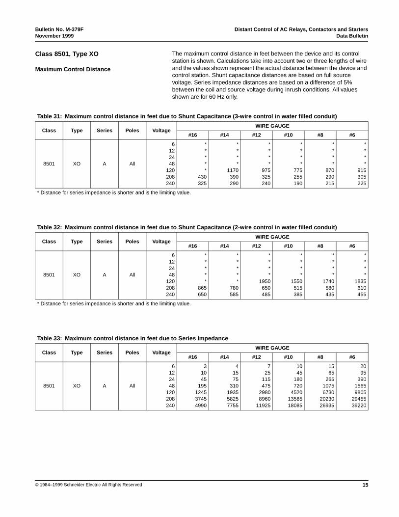
The maximum control distance in feet between the device and its controlstation is shown. Calculations take into account two or three lengths of wireand the values shown represent the actual distance between the device andcontrol station. Shunt capacitance distances are based on full sourcevoltage. Series impedance distances are based on a difference of 5%between the coil and source voltage during inrush conditions. All valuesshown are for 60 Hz only.
Class 8501, Type XO
Maximum Control Distance
Table 31: Maximum control distance in feet due to Shunt Capacitance (3-wire control in water filled conduit)
Class Type Series Poles VoltageWIRE GAUGE
#16 #14 #12 #10 #8 #6
8501 XO A All
6122448
120208240
*****
430325
****
1170390290
****
975325240
****
775255190
****
870290215
****
915305225
* Distance for series impedance is shorter and is the limiting value.
Table 32: Maximum control distance in feet due to Shunt Capacitance (2-wire control in water filled conduit)
Class Type Series Poles VoltageWIRE GAUGE
#16 #14 #12 #10 #8 #6
8501 XO A All
6122448
120208240
*****
865650
*****
780585
****
1950650485
****
1550515385
****
1740580435
****
1835610455
* Distance for series impedance is shorter and is the limiting value.
Table 33: Maximum control distance in feet due to Series Impedance
Class Type Series Poles VoltageWIRE GAUGE
#16 #14 #12 #10 #8 #6
8501 XO A All
6122448
120208240
31045
195124537454990
41575
310193558257755
725
115475
29808960
11925
1045
180720
45201358518085
1565
26510756730
2023026935
2095
39015659805
2945539220
Distant Control of AC Relays, Contactors and Starters Bulletin No. M-379FData Bulletin November 1999
16 © 1984–1999 Schneider Electric All Rights Reserved
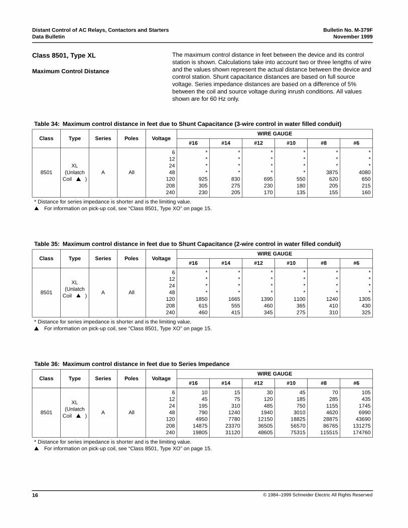
The maximum control distance in feet between the device and its controlstation is shown. Calculations take into account two or three lengths of wireand the values shown represent the actual distance between the device andcontrol station. Shunt capacitance distances are based on full sourcevoltage. Series impedance distances are based on a difference of 5%between the coil and source voltage during inrush conditions. All valuesshown are for 60 Hz only.
Class 8501, Type XL
Maximum Control Distance
Table 34: Maximum control distance in feet due to Shunt Capacitance (3-wire control in water filled conduit)
Class Type Series Poles VoltageWIRE GAUGE
#16 #14 #12 #10 #8 #6
8501XL
(UnlatchCoil� �� )
A All
6122448
120208240
****
925305230
****
830275205
****
695230170
****
550180135
***
3875620205155
***
4080650215160
* Distance for series impedance is shorter and is the limiting value.�� For information on pick-up coil, see “Class 8501, Type XO” on page 15.
Table 35: Maximum control distance in feet due to Shunt Capacitance (2-wire control in water filled conduit)
Class Type Series Poles VoltageWIRE GAUGE
#16 #14 #12 #10 #8 #6
8501
XL(Unlatch
Coil� �� )A All
6122448
120208240
****
1850615460
****
1665555415
****
1390460345
****
1100365275
****
1240410310
****
1305430325
* Distance for series impedance is shorter and is the limiting value.�� For information on pick-up coil, see “Class 8501, Type XO” on page 15.
Table 36: Maximum control distance in feet due to Series Impedance
Class Type Series Poles VoltageWIRE GAUGE
#16 #14 #12 #10 #8 #6
8501
XL(Unlatch
Coil� �� )A All
6122448
120208240
1045
195790
49501487519805
1575
31012407780
2337031120
30120485
1940121503650548605
45185750
3010188255657075315
70285
11554620
2887586765
115515
105435
17456990
43690131275174760
* Distance for series impedance is shorter and is the limiting value.�� For information on pick-up coil, see “Class 8501, Type XO” on page 15.
Bulletin No. M-379F Distant Control of AC Relays, Contactors and StartersNovember 1999 Data Bulletin
17© 1984–1999 Schneider Electric All Rights Reserved
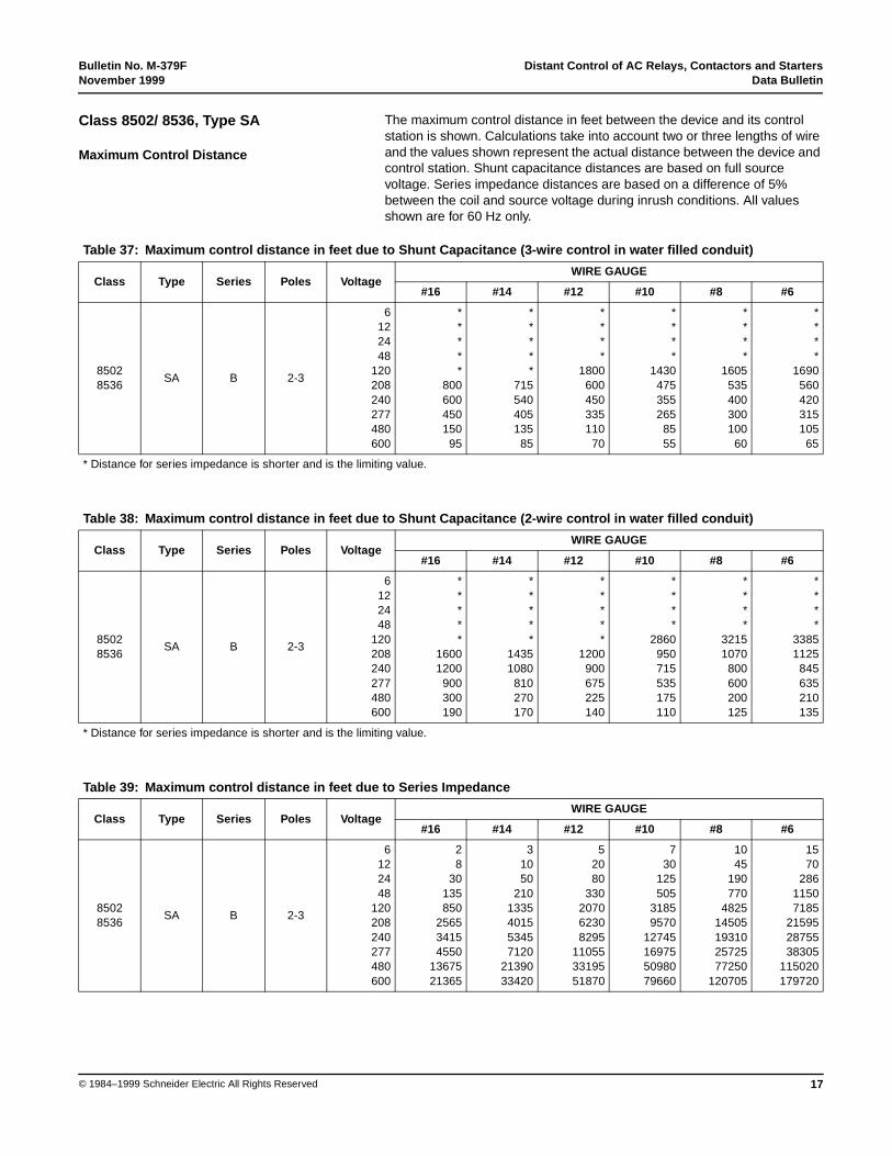
The maximum control distance in feet between the device and its controlstation is shown. Calculations take into account two or three lengths of wireand the values shown represent the actual distance between the device andcontrol station. Shunt capacitance distances are based on full sourcevoltage. Series impedance distances are based on a difference of 5%between the coil and source voltage during inrush conditions. All valuesshown are for 60 Hz only.
Class 8502/ 8536, Type SA
Maximum Control Distance
Table 37: Maximum control distance in feet due to Shunt Capacitance (3-wire control in water filled conduit)
Class Type Series Poles VoltageWIRE GAUGE
#16 #14 #12 #10 #8 #6
85028536
SA B 2-3
6122448
120208240277480600
*****
800600450150
95
*****
715540405135
85
****
1800600450335110
70
****
1430475355265
8555
****
1605535400300100
60
****
1690560420315105
65
* Distance for series impedance is shorter and is the limiting value.
Table 38: Maximum control distance in feet due to Shunt Capacitance (2-wire control in water filled conduit)
Class Type Series Poles VoltageWIRE GAUGE
#16 #14 #12 #10 #8 #6
85028536
SA B 2-3
6122448
120208240277480600
*****
16001200
900300190
*****
14351080
810270170
*****
1200900675225140
****
2860950715535175110
****
32151070
800600200125
****
33851125
845635210135
* Distance for series impedance is shorter and is the limiting value.
Table 39: Maximum control distance in feet due to Series Impedance
Class Type Series Poles VoltageWIRE GAUGE
#16 #14 #12 #10 #8 #6
85028536
SA B 2-3
6122448
120208240277480600
28
30135850
256534154550
1367521365
31050
2101335401553457120
2139033420
52080
330207062308295
110553319551870
730
125505
31859570
12745169755098079660
1045
190770
482514505193102572577250
120705
1570
28611507185
215952875538305
115020179720
Distant Control of AC Relays, Contactors and Starters Bulletin No. M-379FData Bulletin November 1999
18 © 1984–1999 Schneider Electric All Rights Reserved
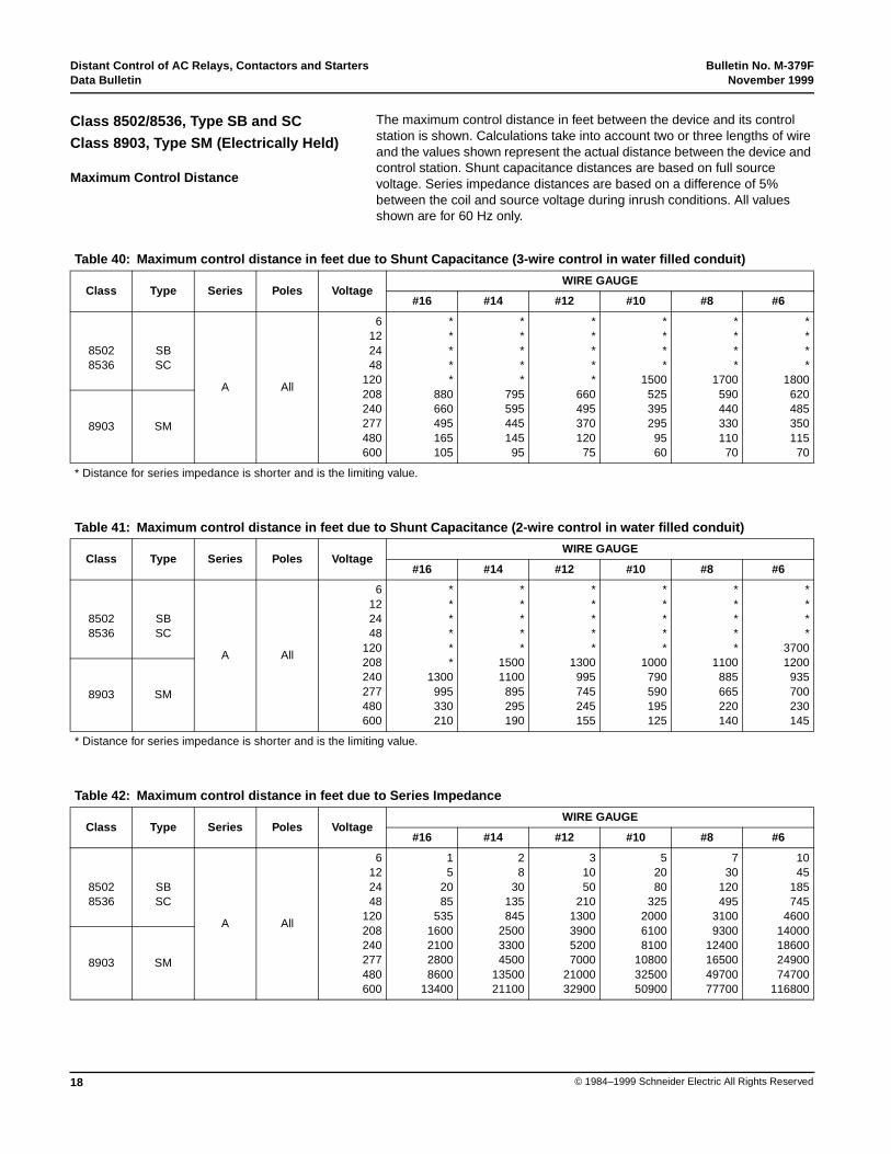
The maximum control distance in feet between the device and its controlstation is shown. Calculations take into account two or three lengths of wireand the values shown represent the actual distance between the device andcontrol station. Shunt capacitance distances are based on full sourcevoltage. Series impedance distances are based on a difference of 5%between the coil and source voltage during inrush conditions. All valuesshown are for 60 Hz only.
Class 8502/8536, Type SB and SC
Class 8903, Type SM (Electrically Held)
Maximum Control Distance
Table 40: Maximum control distance in feet due to Shunt Capacitance (3-wire control in water filled conduit)
Class Type Series Poles VoltageWIRE GAUGE
#16 #14 #12 #10 #8 #6
85028536
SBSC
A All
6122448
120208240277480600
*****
880660495165105
*****
795595445145
95
*****
660495370120
75
****
1500525395295
9560
****
1700590440330110
70
****
1800620485350115
70
8903 SM
* Distance for series impedance is shorter and is the limiting value.
Table 41: Maximum control distance in feet due to Shunt Capacitance (2-wire control in water filled conduit)
Class Type Series Poles VoltageWIRE GAUGE
#16 #14 #12 #10 #8 #6
85028536
SBSC
A All
6122448
120208240277480600
******
1300995330210
*****
15001100
895295190
*****
1300995745245155
*****
1000790590195125
*****
1100885665220140
****
37001200
935700230145
8903 SM
* Distance for series impedance is shorter and is the limiting value.
Table 42: Maximum control distance in feet due to Series Impedance
Class Type Series Poles VoltageWIRE GAUGE
#16 #14 #12 #10 #8 #6
85028536
SBSC
A All
6122448
120208240277480600
15
2085
5351600210028008600
13400
28
30135845
250033004500
1350021100
31050
2101300390052007000
2100032900
52080
325200061008100
108003250050900
730
120495
31009300
12400165004970077700
1045
185745
460014000186002490074700
116800
8903 SM
Bulletin No. M-379F Distant Control of AC Relays, Contactors and StartersNovember 1999 Data Bulletin
19© 1984–1999 Schneider Electric All Rights Reserved
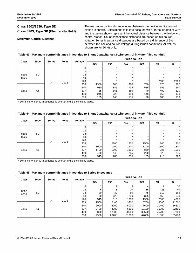
The maximum control distance in feet between the device and its controlstation is shown. Calculations take into account two or three lengths of wireand the values shown represent the actual distance between the device andcontrol station. Shunt capacitance distances are based on full sourcevoltage. Series impedance distances are based on a difference of 5%between the coil and source voltage during inrush conditions. All valuesshown are for 60 Hz only.
Class 8502/8536, Type SD
Class 8903, Type SP (Electrically Held)
Maximum Control Distance
Table 43: Maximum control distance in feet due to Shunt Capacitance (3-wire control in water filled conduit)
Class Type Series Poles VoltageWIRE GAUGE
#16 #14 #12 #10 #8 #6
85028536
SD
A 2 & 3
6122448
120208240277480600
*****
1300980735245155
*****
1100885665220140
*****
980735550180115
*****
780585440145
90
****
2600875655490160105
****
2700920690520170110
8903 SP
* Distance for series impedance is shorter and is the limiting value.
Table 44: Maximum control distance in feet due to Shunt Capacitance (2-wire control in water filled conduit)
Class Type Series Poles VoltageWIRE GAUGE
#16 #14 #12 #10 #8 #6
85028536
SD
A 2 & 3
6122448
120208240277480600
******
19001400
490315
*****
230017001300
440280
*****
190014001100
365235
*****
15001100
880290185
*****
17001300
985325210
*****
180013001000
345220
8903 SP
* Distance for series impedance is shorter and is the limiting value.
Table 45: Maximum control distance in feet due to Series Impedance
Class Type Series Poles VoltageWIRE GAUGE
#16 #14 #12 #10 #8 #6
85028536
SD
A 2 & 3
6122448
120208240277480600
15
2080
5151500200027008300
12900
28
30125810
240032004300
1290020200
31050
2001200370050006600
2000031200
41575
305190057007600
101003050047600
725
110455
28008500
11400152004570071500
1040
165670
420012600168002240067200
105100
8903 SP
Distant Control of AC Relays, Contactors and Starters Bulletin No. M-379FData Bulletin November 1999
20 © 1984–1999 Schneider Electric All Rights Reserved
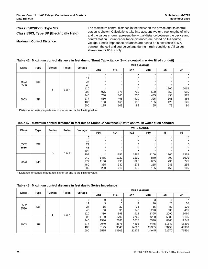
The maximum control distance in feet between the device and its controlstation is shown. Calculations take into account two or three lengths of wireand the values shown represent the actual distance between the device andcontrol station. Shunt capacitance distances are based on full sourcevoltage. Series impedance distances are based on a difference of 5%between the coil and source voltage during inrush conditions. All valuesshown are for 60 Hz only.
Class 8502/8536, Type SD
Class 8903, Type SP (Electrically Held)
Maximum Control Distance
Table 46: Maximum control distance in feet due to Shunt Capacitance (3-wire control in water filled conduit)
Class Type Series Poles VoltageWIRE GAUGE
#16 #14 #12 #10 #8 #6
85028536
SD
A 4 & 5
6122448
120208240277480600
*****
975730550180115
*****
875660495165105
*****
730550410135
85
*****
580435325105
65
****
1960650490365120
75
****
2065685515385125
80
8903 SP
* Distance for series impedance is shorter and is the limiting value.
Table 47: Maximum control distance in feet due to Shunt Capacitance (2-wire control in water filled conduit)
Class Type Series Poles VoltageWIRE GAUGE
#16 #14 #12 #10 #8 #6
85028536
SD
A 4 & 5
6122448
120208240277480600
******
14651100
365230
*****
17551320
990330210
*****
14651100
825275175
*****
1160870655215135
*****
1305890735245155
*****
13751030
775255165
8903 SP
* Distance for series impedance is shorter and is the limiting value.
Table 48: Maximum control distance in feet due to Series Impedance
Class Type Series Poles VoltageWIRE GAUGE
#16 #14 #12 #10 #8 #6
85028536
SD
A 4 & 5
6122448
120208240277480600
03
1560
38011501530204061259575
15
2095
5951790238531759540
14905
29
35145915
276036754895
1470022975
31055
2201395420055907445
2236534945
52080
330209062808360
111403345052270
730
120485
30609195
12245163104898076530
8903 SP
Bulletin No. M-379F Distant Control of AC Relays, Contactors and StartersNovember 1999 Data Bulletin
21© 1984–1999 Schneider Electric All Rights Reserved
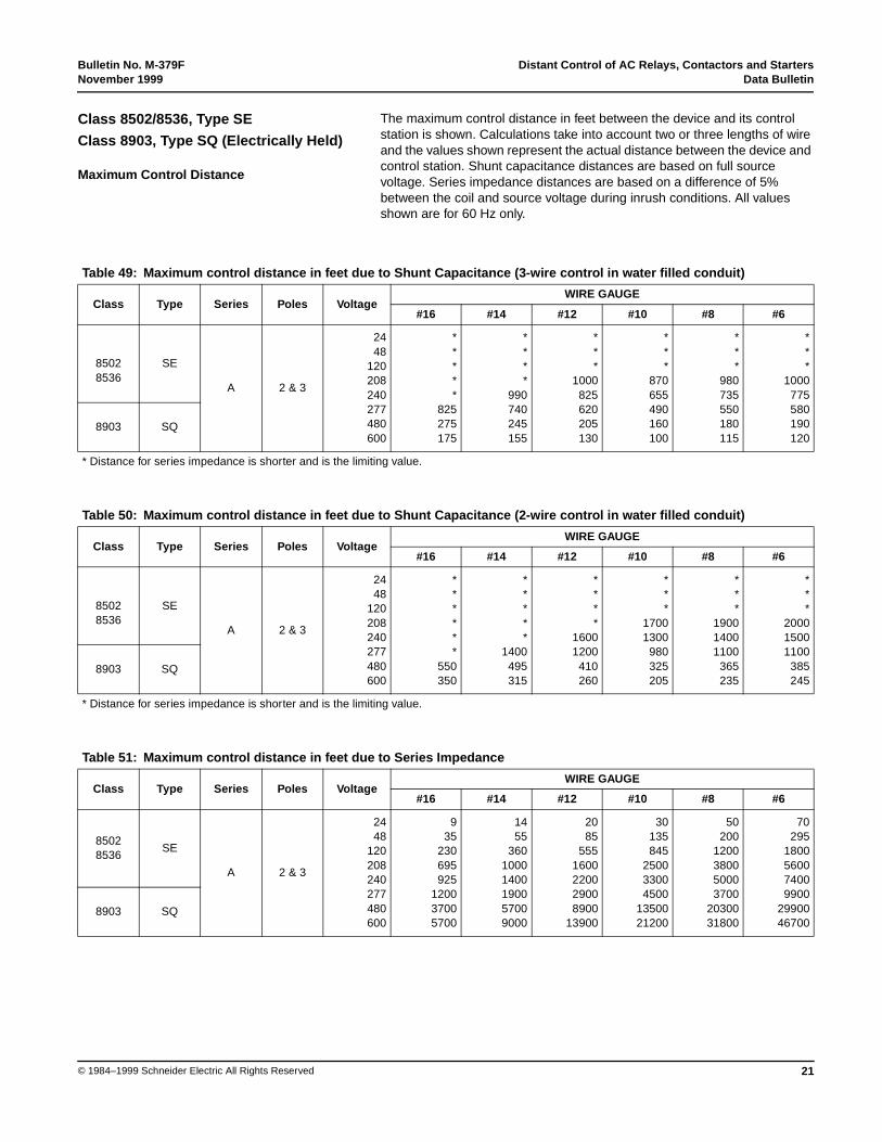
The maximum control distance in feet between the device and its controlstation is shown. Calculations take into account two or three lengths of wireand the values shown represent the actual distance between the device andcontrol station. Shunt capacitance distances are based on full sourcevoltage. Series impedance distances are based on a difference of 5%between the coil and source voltage during inrush conditions. All valuesshown are for 60 Hz only.
Class 8502/8536, Type SE
Class 8903, Type SQ (Electrically Held)
Maximum Control Distance
Table 49: Maximum control distance in feet due to Shunt Capacitance (3-wire control in water filled conduit)
Class Type Series Poles VoltageWIRE GAUGE
#16 #14 #12 #10 #8 #6
85028536
SE
A 2 & 3
2448
120208240277480600
*****
825275175
****
990740245155
***
1000825620205130
***
870655490160100
***
980735550180115
***
1000775580190120
8903 SQ
* Distance for series impedance is shorter and is the limiting value.
Table 50: Maximum control distance in feet due to Shunt Capacitance (2-wire control in water filled conduit)
Class Type Series Poles VoltageWIRE GAUGE
#16 #14 #12 #10 #8 #6
85028536
SE
A 2 & 3
2448
120208240277480600
******
550350
*****
1400495315
****
16001200
410260
***
17001300
980325205
***
190014001100
365235
***
200015001100
385245
8903 SQ
* Distance for series impedance is shorter and is the limiting value.
Table 51: Maximum control distance in feet due to Series Impedance
Class Type Series Poles VoltageWIRE GAUGE
#16 #14 #12 #10 #8 #6
85028536
SE
A 2 & 3
2448
120208240277480600
935
230695925
120037005700
1455
36010001400190057009000
2085
5551600220029008900
13900
30135845
250033004500
1350021200
50200
1200380050003700
2030031800
70295
1800560074009900
2990046700
8903 SQ
Distant Control of AC Relays, Contactors and Starters Bulletin No. M-379FData Bulletin November 1999
22 © 1984–1999 Schneider Electric All Rights Reserved
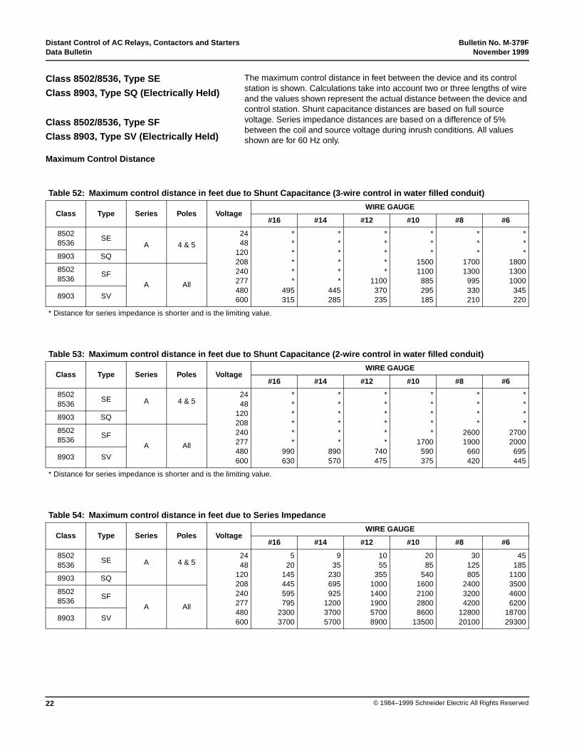
The maximum control distance in feet between the device and its controlstation is shown. Calculations take into account two or three lengths of wireand the values shown represent the actual distance between the device andcontrol station. Shunt capacitance distances are based on full sourcevoltage. Series impedance distances are based on a difference of 5%between the coil and source voltage during inrush conditions. All valuesshown are for 60 Hz only.
Class 8502/8536, Type SE
Class 8903, Type SQ (Electrically Held)
Class 8502/8536, Type SF
Class 8903, Type SV (Electrically Held)
Maximum Control Distance
Table 52: Maximum control distance in feet due to Shunt Capacitance (3-wire control in water filled conduit)
Class Type Series Poles VoltageWIRE GAUGE
#16 #14 #12 #10 #8 #6
85028536
SEA 4 & 5
2448
120208240277480600
******
495315
******
445285
*****
1100370235
***
15001100
885295185
***
17001300
995330210
***
180013001000
345220
8903 SQ
85028536
SFA All
8903 SV
* Distance for series impedance is shorter and is the limiting value.
Table 53: Maximum control distance in feet due to Shunt Capacitance (2-wire control in water filled conduit)
Class Type Series Poles VoltageWIRE GAUGE
#16 #14 #12 #10 #8 #6
85028536
SE A 4 & 52448
120208240277480600
******
990630
******
890570
******
740475
*****
1700590375
****
26001900
660420
****
27002000
695445
8903 SQ
85028536
SFA All
8903 SV
* Distance for series impedance is shorter and is the limiting value.
Table 54: Maximum control distance in feet due to Series Impedance
Class Type Series Poles VoltageWIRE GAUGE
#16 #14 #12 #10 #8 #6
85028536
SE A 4 & 52448
120208240277480600
520
145445595795
23003700
935
230695925
120037005700
1055
35510001400190057008900
2085
5401600210028008600
13500
30125805
240032004200
1280020100
45185
1100350046006200
1870029300
8903 SQ
85028536
SFA All
8903 SV
Bulletin No. M-379F Distant Control of AC Relays, Contactors and StartersNovember 1999 Data Bulletin
23© 1984–1999 Schneider Electric All Rights Reserved
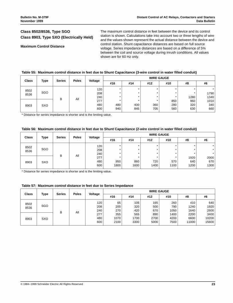
The maximum control distance in feet between the device and its controlstation is shown. Calculations take into account two or three lengths of wireand the values shown represent the actual distance between the device andcontrol station. Shunt capacitance distances are based on full sourcevoltage. Series impedance distances are based on a difference of 5%between the coil and source voltage during inrush conditions. All valuesshown are for 60 Hz only.
Class 8502/8536, Type SGO
Class 8903, Type SXO (Electrically Held)
Maximum Control Distance
Table 55: Maximum control distance in feet due to Shunt Capacitance (3-wire control in water filled conduit)
Class Type Series Poles VoltageWIRE GAUGE
#16 #14 #12 #10 #8 #6
85028536
SGO
B All
120208240277480600
****
480940
****
430845
****
360705
***
850280560
**
1280960320630
*179013401010
340660
8903 SXO
* Distance for series impedance is shorter and is the limiting value.
Table 56: Maximum control distance in feet due to Shunt Capacitance (2-wire control in water filled conduit)
Class Type Series Poles VoltageWIRE GAUGE
#16 #14 #12 #10 #8 #6
85028536
SGO
B All
120208240277480600
****
9501800
****
8601600
****
7201400
****
5701100
***
1920640
1200
***
2000670
13008903 SXO
* Distance for series impedance is shorter and is the limiting value.
Table 57: Maximum control distance in feet due to Series Impedance
Class Type Series Poles VoltageWIRE GAUGE
#16 #14 #12 #10 #8 #6
85028536
SGO
B All
120208240277480600
65200270355
10702100
105320420565
17003300
165500670890
27005000
260790
1050140042007500
4101240164022006600
11000
640192026003400
1020015600
8903 SXO
Distant Control of AC Relays, Contactors and Starters Bulletin No. M-379FData Bulletin November 1999
24 © 1984–1999 Schneider Electric All Rights Reserved
The maximum control distance in feet between the device and its controlstation is shown. Calculations take into account two or three lengths of wireand the values shown represent the actual distance between the device andcontrol station. Shunt capacitance distances are based on full sourcevoltage. Series impedance distances are based on a difference of 5%between the coil and source voltage during inrush conditions. All valuesshown are for 60 Hz only.
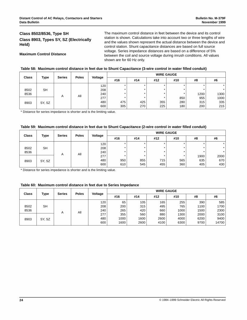
Class 8502/8536, Type SH
Class 8903, Types SY, SZ (ElectricallyHeld)
Maximum Control Distance
Table 58: Maximum control distance in feet due to Shunt Capacitance (3-wire control in water filled conduit)
Class Type Series Poles VoltageWIRE GAUGE
#16 #14 #12 #10 #8 #6
85028536
SH
A All
120208240277480600
****
475305
****
425270
****
355225
***
850280180
**
1200955315200
**
13001000
335215
8903 SY, SZ
* Distance for series impedance is shorter and is the limiting value.
Table 59: Maximum control distance in feet due to Shunt Capacitance (2-wire control in water filled conduit)
Class Type Series Poles VoltageWIRE GAUGE
#16 #14 #12 #10 #8 #6
85028536
SH
A All
120208240277480600
****
950610
****
855545
****
715455
****
565360
***
1900635405
***
2000670430
8903 SY, SZ
* Distance for series impedance is shorter and is the limiting value.
Table 60: Maximum control distance in feet due to Series Impedance
Class Type Series Poles VoltageWIRE GAUGE
#16 #14 #12 #10 #8 #6
85028536
SH
A All
120208240277480600
65200265355
10001600
105315420560
16002600
165495660880
26004100
255765
1000130040006300
39011001500200062009700
5851700230031009400
147008903 SY, SZ

Bulletin No. M-379F Distant Control of AC Relays, Contactors and StartersNovember 1999 Data Bulletin
25© 1984–1999 Schneider Electric All Rights Reserved
The maximum control distance in feet between the device and its controlstation is shown. Calculations take into account two or three lengths of wireand the values shown represent the actual distance between the device andcontrol station. Shunt capacitance distances are based on full sourcevoltage. Series impedance distances are based on a difference of 5%between the coil and source voltage during inrush conditions. All valuesshown are for 60 Hz only.
Class 8502/8536, Type SJ
Class 8903, Types SJ (Electrically Held)
Maximum Control Distance
Table 61: Maximum control distance in feet due to Shunt Capacitance (3-wire control in water filled conduit)
Class Type Series Poles VoltageWIRE GAUGE
#16 #14 #12 #10 #8 #6
850285368903
SJ A All
120208240277480600
****
255160
****
230145
***
575190120
**
610455150
95
**
685510170105
*960720540180115
* Distance for series impedance is shorter and is the limiting value.
Table 62: Maximum control distance in feet due to Shunt Capacitance (3-wire control in water filled conduit)
Class Type Series Poles VoltageWIRE GAUGE
#16 #14 #12 #10 #8 #6
850285368903
SJ A All
120208240277480600
****
510325
****
460295
****
380245
***
915305195
***
1025340215
**
14401080
360230
* Distance for series impedance is shorter and is the limiting value.
Table 63: Maximum control distance in feet due to Series Impedance
Class Type Series Poles VoltageWIRE GAUGE
#16 #14 #12 #10 #8 #6
850285368903
SJ A All
120208240277480600
40130175235710
1110
70210280375
11251760
110335445590
17802785
175525700935
28104395
275830
1105147044206910
4301295173023006920
10810
Distant Control of AC Relays, Contactors and Starters Bulletin No. M-379FData Bulletin November 1999
26 © 1984–1999 Schneider Electric All Rights Reserved
The maximum control distance in feet between the device and its controlstation is shown. Calculations take into account two or three lengths of wireand the values shown represent the actual distance between the device andcontrol station. Shunt capacitance distances are based on full sourcevoltage. Series impedance distances are based on a difference of 5%between the coil and source voltage during inrush conditions. All valuesshown are for 60 Hz only.
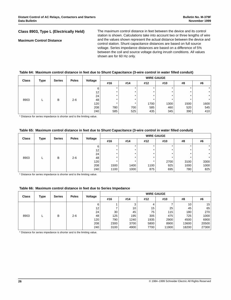
Class 8903, Type L (Electrically Held)
Maximum Control Distance
Table 64: Maximum control distance in feet due to Shunt Capacitance (3-wire control in water filled conduit)
Class Type Series Poles VoltageWIRE GAUGE
#16 #14 #12 #10 #8 #6
8903 L B 2-6
6122448
120208240
*****
780585
*****
700525
****
1700585435
****
1300460345
****
1500520390
****
1600545410
* Distance for series impedance is shorter and is the limiting value.
Table 65: Maximum control distance in feet due to Shunt Capacitance (3-wire control in water filled conduit)
Class Type Series Poles VoltageWIRE GAUGE
#16 #14 #12 #10 #8 #6
8903 L B 2-6
6122448
120208240
*****
15001100
*****
14001000
*****
1100875
****
2700925695
****
31001000
780
****
33001000
825
* Distance for series impedance is shorter and is the limiting value.
Table 66: Maximum control distance in feet due to Series Impedance
Class Type Series Poles VoltageWIRE GAUGE
#16 #14 #12 #10 #8 #6
8903 L B 2-6
6122448
120208240
17
30125790
23003100
31045
195124037004900
41575
305193558007700
725
115475
29008900
11900
1045
180725
45001360018200
1565
27010006900
2050027300
* Distance for series impedance is shorter and is the limiting value.
Bulletin No. M-379F Distant Control of AC Relays, Contactors and StartersNovember 1999 Data Bulletin
27© 1984–1999 Schneider Electric All Rights Reserved
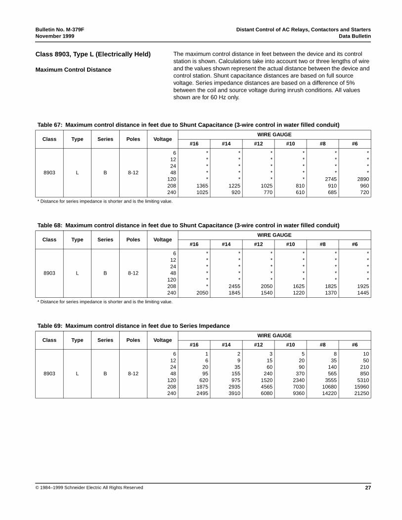
The maximum control distance in feet between the device and its controlstation is shown. Calculations take into account two or three lengths of wireand the values shown represent the actual distance between the device andcontrol station. Shunt capacitance distances are based on full sourcevoltage. Series impedance distances are based on a difference of 5%between the coil and source voltage during inrush conditions. All valuesshown are for 60 Hz only.
Class 8903, Type L (Electrically Held)
Maximum Control Distance
Table 67: Maximum control distance in feet due to Shunt Capacitance (3-wire control in water filled conduit)
Class Type Series Poles VoltageWIRE GAUGE
#16 #14 #12 #10 #8 #6
8903 L B 8-12
6122448
120208240
*****
13651025
*****
1225920
*****
1025770
*****
810610
****
2745910685
****
2890960720
* Distance for series impedance is shorter and is the limiting value.
Table 68: Maximum control distance in feet due to Shunt Capacitance (3-wire control in water filled conduit)
Class Type Series Poles VoltageWIRE GAUGE
#16 #14 #12 #10 #8 #6
8903 L B 8-12
6122448
120208240
******
2050
*****
24551845
*****
20501540
*****
16251220
*****
18251370
*****
19251445
* Distance for series impedance is shorter and is the limiting value.
Table 69: Maximum control distance in feet due to Series Impedance
Class Type Series Poles VoltageWIRE GAUGE
#16 #14 #12 #10 #8 #6
8903 L B 8-12
6122448
120208240
16
2095
62018752495
29
35155975
29353910
31560
240152045656080
52090
370234070309360
835
140565
35551068014220
1050
210850
53101596021250
Electrical equipment should be serviced only by qualified electrical maintenance personnel. Noresponsibility is assumed by Schneider Electric for any consequences arising out of the use of thismaterial.
Distant Control of AC Relays, Contactors and Starters Bulletin No. M-379FData Bulletin November 1999
Square D Company8001 Hwy 64 EastKnightdale, NC 27545888-SquareD (778-2733)www.squared.com
© 1984–1999 Schneider Electric All Rights Reserved28