disassembly & assembly instructions single stage...
TRANSCRIPT
(Rev. 2.0_10-2010)
DISASSEMBLY & ASSEMBLY INSTRUCTIONS SINGLE STAGE
CENTRIFUGAL PUMPS
TC... MCU-...
Disassembly & assembly instructions single stage centrifugal pumps TC… - MCU-… 2
INTRODUCTION These instructions are for the maintenance personnel for maintenance and/or repair of the indicated pump series. Disassembly and assembly require expertise and knowledge of the procedures, therefore the work must be carried out by qualified personnel. These instructions must be carefully read and understood in conjunction with the section drawings and tables contained in the manual and enclosed, prior to attempt any work on the pumps. For safety, installation and maintenance instructions consult the manual “INSTALLATION & OPERATING INSTRUCTIONS FOR CENTRIFUGAL PUMPS” attached to the pump at time of shipment. Consult also any other attached instructions for accessories and/or components included with the pumps such as mechanical seals, heat exchangers, flushing systems, instrumentation, etc. Before operating or working on the pump it is recommended to adopt safety precautions wearing safety attire (hat, glasses, gloves, shoes, etc.) and have ready the necessary tools required for the work to be done. Do not subject the pump of its components to sudden mechanical impacts and /or distortions. Do not damage or scratch the sealing faces. Pay particular attention not to damage flat gaskets and O-Rings. Careful not to leave foreign matters such as moults, screws, washers, rags, etc. in the pump. When requesting spare parts or technical information for the pump, always quote the pump model number and serial number which is printed on the pump nameplate: therefore it is recommended not to remove the pump nameplate or, in case this action will be necessary, write the serial number on the pump (for example on the flange). Should additional information be required, please do not hesitate to contact POMPETRAVAINI or the closest representative. Should there be any difficulties in repairing the pump, it is recommended to send the pump for repair to POMPETRAVAINI or the local authorised representative. Pump repairs and/or service carried out by customer or unauthorised personnel are not guaranteed by POMPETRAVAINI or by its subsidiaries. Note: Pump parts list identify all pump components by item number (VDMA) in connection with the sectional drawings.
All drawings are for reference purpose and not are certified for construction, however should additional information be required, contact POMPETRAVAINI or its closest representative.
INDEX
1 - Steps to be followed prior to pump disassembly 2 - Disassembly and assembly of pumps series TCH - TCT - TCA & MCU-CH / CHT / CHA group 1 - 2 - 3 2.1 - Disassembly 2.2 - Assembly 3 - Disassembly and assembly of pumps series MCU-CH group 3 NS and 4 NS 3.1 - Disassembly 3.2 - Assembly 4 - Disassembly and assembly of pumps series TCD and MCU-OD 4.1 - Disassembly 4.2 - Assembly 5 - Mechanical seals assembly 5.1 - Pumps series TCH - TCT - TCA - MCU-CH - MCU-CHT - MCU-CHA 5.2 - Pumps series TCD - TCD/SP - MCU-OD - MCU-OD/SP 6 - Replacing the packing rings 7 - Spare parts 8 - Section drawings and typical options 9 - Nomenclature of pump parts 10 - Engineering tables
The liquids handled by the pumps and also their parts could be potentially dangerous for persons and environment: provide their eventual disposal in conformity with the laws into force and a proper environment management.
The present manual is not assigned for pumps subjected to the ATEX 94/9/CE directive. In case the pump is assigned in environments subjected to the application ATEX 99/92/CE directive or in case the pump is provided with a nameplate indicating the ATEX stamp, it strictly forbidden proceed to start up the pumps but necessary to consult POMPETRAVAINI for clarifications. For pumps subjected to the ATEX 94/9/CE directive it is available a dedicated integrative manual.
In preparing this manual, every possible effort has been made to help the customer and operator with the proper installation and operation of the pump. Should you find errors, misunderstandings or discrepancies please do not hesitate to bring them to our attention.
Disassembly & assembly instructions single stage centrifugal pumps TC… - MCU-… 3
1 - STEPS TO BE FOLLOWED PRIOR TO PUMP DISASSEMBLY Should pump repairs be required, it is recommended to acquire full familiarity of the procedures to be followed by studying these instructions and the “Operating Manual for Centrifugal Pumps”.
FOLLOW THE SAFETY INSTRUCTIONS LISTED UNDER CHAPTER 2 OF THE AFORE MENTIONED OPERATING MANUAL.
It is important to adhere to the following before working on the pump: - use the appropriate steps to stop the pump - close the isolating valves at suction and discharge piping - wear the safety clothing (hard hat, safety glasses, gloves, safety booths, etc.) - disconnect the electrical power to the motor and all the electrical instrumentation and, if necessary, disconnect the
electrical cables - if the pump is handling hot liquids, let it cool down to ambient temperature - drain the pump casing through by removing the drain plugs, rinse the pump with neutral liquid, if required
- adopt all safety precautions when the pump handles hazardous liquids, pollutant or toxic; these liquids as well as the liquid used for rinsing the pump must be collected and disposed of with the maximum caution and always in compliance with the local safety regulations.
To remove the pump and the motor (if required) from the installation proceed as follows: - remove the bolts on the suction and discharge flanges - disconnect any flushing lines, accessories and/or instrumentation connected to the pump assembly - remove the coupling guard - remove the coupling spacer, if present - remove the motor, if necessary, by removing the anchor bolts from motor feet or from the motor flange in the case of
monoblock assemblies - remove the pump by removing the bolts from the pump’s feet - disconnect the pump from the installation with caution, do not damage any components - refer to the “Operating manual for centrifugal pumps” for instructions on transporting the pump.
2 - DISASSEMBLY AND ASSEMBLY OF PUMPS SERIES
TCH - TCT - TCA MCU-CH / CHT / CHA group 1 - 2 - 3
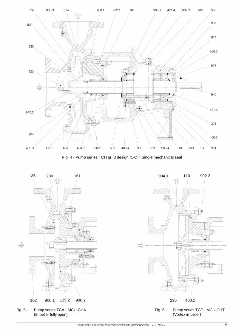
2.1 - DISASSEMBLY (See the section drawings from fig. 2 to fig. 11 of chapter 8). Remove the oil from the bearing frame through the draining plug VDMA 903.4 (dispose of the oil in compliance with the local safety regulations). Remove the bolts from the studs VDMA 902.2, this allows removal of the rotor from the pump casing. Pumps with vortex impeller (series TCT and MCU-CHT) are fitted with spacer ring VDMA 110 which must be removed from the casing or from the casing cover. Remove the impeller nut VDMA 922 (for cast iron construction) or VDMA 925 (for stainless steel construction) so that the impeller VDMA 230 can then be removed from the shaft VDMA 210, remove then the key VDMA 940.2. Pumps with open impeller (series TCA and MCU-CHA) are fitted with two wear plates VDMA 135 and 135.2; to remove the wear plates the screws VDMA 900.1 and 900.2 must be removed. Remove the bolts from studs VDMA 902.1, if pump is fitted with mechanical seal, remove the bolts from the studs VDMA 902 of the seal cover and separate the casing cover VDMA 161 from frame VDMA 330. The seal stationary face if fitted in the seal cover, remove it if replacement is required. For pumps with packed stuffing box it is required to remove the nuts from studs VDMA 902.3, remove the seal gland VDMA 452 attached to the cooling cover VDMA 165 and finally remove the packing rings VDMA 461. Removal of mechanical seal(s) and of packing should be carried out carefully to prevent damaging any of the various components. Remove the shaft sleeve VDMA 524 with the seal rotating element still on the sleeve together with the locating ring VDMA 485. If the locating ring requires replacement be sure to mark its location prior to removal. For “CARTRIDGE” type mechanical seal insert the seal spacers prior to removal of the seal. The seal spacers will block the seal with its sleeve, loosen then the set screws that lock seal sleeve to the pump shaft, remove the nuts from the studs that attach the seal flange to the pump and slide the Seal Cartridge out. To completely disassemble the bearing frame proceed as described below. Remove the splash ring VDMA 507. With a gear puller remove the half coupling from the pump shaft and the key VDMA 940. When dealing with Monoblock design remove also the lantern VDMA 341. Remove the two bearing covers VDMA 360.1 and/or 360.2 complete of radial seal rings VDMA 421 and 421.1 or 421.5. Remove the retaining rings VDMA 932 or bearing nut VDMA 923, applying a slight pressure push the shaft out, together with the bearings, toward the free end. The pressure should be such that the axially fixed bearing will be removed from the shaft. The last bearing should be removed from the shaft with the help of a gear puller.
Disassembly & assembly instructions single stage centrifugal pumps TC… - MCU-… 4
2.2 - ASSEMBLY Visually and dimensionally examine the components to be replaced. Verify the integrity of the component and quantify the degree of wear (for the main dimensions see tab. 2 - 3 - 4 - 6 of chapter 10). When new parts are required always insist on original parts from POMPETRAVAINI. In case of doubts or should there be any questions regarding the above, do not hesitate to contact POMPETRAVAINI or the nearest authorised representative. To replace the wear ring VDMA 502 it is required to loosen the set screws VDMA 904, using a puller or in the event of difficulty the wear ring can be machined on a lathe. Pumps with open impeller (series TCA and MCU-CHA) must have the proper clearance between the wear plates and the impeller (contact the factory for specific values). It is good practice to replace all gaskets and packing rings (even if they do not show evidence of defects), bearings and mechanical seals that show wear grooves and excessive tolerances. Clean each components using suitable cleaning agents and compatible with the materials of construction. Bearings must be decreased with a solvent such as Naphtha, allow them to dry and then lubricate with oil. To help with the bearing installation it is recommended to pre-heat the bearings to approximately 80 0C. If there are no complications and the components do not show any defects, wear and scratches on the sealing faces, the assembly steps will be by proceeding the reverse of the disassembly. Fitting of mechanical seals or packing rings are described in chapters 5 or 6. See chapter 10, tab. 2 - 3 - 4, for dimensions details. During assembly the fitting of the various components must be free of interference and damages. For a positive placement of the gaskets it is suggested to use a compatible fluid (example oil) to help keeping the gaskets in the sealing area. See fig. 17 of chapter 10 for torque values of bolts and screws. After the assembly it is suggested to hydrotest the pump for leakage. The test pressure should be at least 1.2 times the maximum working pressure ma not less than 4 bar. The seal chamber of pumps fitted with double back to back mechanical seals, should also be pressurised.
3 - DISASSEMBLY AND ASSEMBLY OF PUMPS SERIES
MCU-CH group 3 NS and 4 NS
3.1 - DISASSEMBLY (See the section drawings of fig. 12 - 13 - 14 of chapter 8). Drain the oil from the bearing frame by removing the drain plug VDMA 903.4. Remove the bolts from the studs VDMA 902.2 so that the rotor may be removed from the pump. Place the rotor assembly in the vertical position with the drive end toward the bottom. Loosen the impeller nut VDMA 925 and remove the impeller VDMA 230 from the shaft VDMA 210. Remove the bolts VDMA 914 and remove cover VDMA 471.1 (pay attention to the stationary seal element that is left in the cover, for back to back double seal arrangement). Remove the shaft sleeve VDMA 524 with the seal rotating element still on the sleeve together with the locating ring VDMA 485. If the locating ring requires replacement be sure to mark its location prior to removal. For pumps with packed stuffing box it is required to remove the nuts from studs VDMA 902.3, remove the seal gland VDMA 452 attached to the cooling cover VDMA 165 and finally remove the packing rings VDMA 461. Removal of mechanical seal(s) and of packing should be carried out carefully to prevent damaging any of the various components. Remove the cover VDMA 161 and the mechanical seal cover VDMA 471 or the seal gland VDMA 452. The seal stationary element is still in the seal cover, remove it if replacement is required. For “CARTRIDGE” type mechanical seal insert the seal spacers prior to removal of the seal. The seal spacers will block the seal with its sleeve, loosen then the set screws that lock seal sleeve to the pump shaft, remove the nuts from the studs that attach the seal flange to the pump and slide the Seal Cartridge out. To completely disassemble the bearing frame proceed as described below. Remove the splash ring VDMA 507. With a gear puller remove the half coupling from the pump shaft and the key VDMA 940. Remove the screws VDMA 901.2, remove the casing cover VDMA 163 together with the outer ring of the roller bearing VDMA 323. In the event the outer ring of the roller bearing requires replacement, it is necessary to remove the snap ring VDMA 932.3 and then utilise the external extraction holes. Rotate the bearing frame with the drive shaft end upward, remove screws VDMA 901 and bearing cover VDMA 360.2. Remove the shaft VDMA 210 with bearings VDMA 320. To replace these bearings remove first the bearing nut VDMA 923. 3.2 - ASSEMBLY Assembly procedures are same as given under paragraph 2.2 (for components type and dimensions see tab. 5 of chapter 10).
Disassembly & assembly instructions single stage centrifugal pumps TC… - MCU-… 5
4 - DISASSEMBLY AND ASSEMBLY OF PUMPS SERIES
TCD and MCU-OD
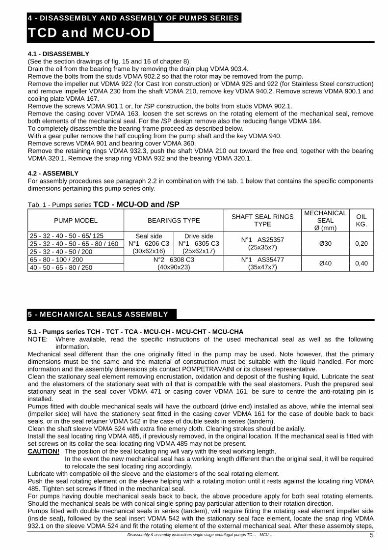
4.1 - DISASSEMBLY (See the section drawings of fig. 15 and 16 of chapter 8). Drain the oil from the bearing frame by removing the drain plug VDMA 903.4. Remove the bolts from the studs VDMA 902.2 so that the rotor may be removed from the pump. Remove the impeller nut VDMA 922 (for Cast Iron construction) or VDMA 925 and 922 (for Stainless Steel construction) and remove impeller VDMA 230 from the shaft VDMA 210, remove key VDMA 940.2. Remove screws VDMA 900.1 and cooling plate VDMA 167. Remove the screws VDMA 901.1 or, for /SP construction, the bolts from studs VDMA 902.1. Remove the casing cover VDMA 163, loosen the set screws on the rotating element of the mechanical seal, remove both elements of the mechanical seal. For the /SP design remove also the reducing flange VDMA 184. To completely disassemble the bearing frame proceed as described below. With a gear puller remove the half coupling from the pump shaft and the key VDMA 940. Remove screws VDMA 901 and bearing cover VDMA 360. Remove the retaining rings VDMA 932.3, push the shaft VDMA 210 out toward the free end, together with the bearing VDMA 320.1. Remove the snap ring VDMA 932 and the bearing VDMA 320.1. 4.2 - ASSEMBLY For assembly procedures see paragraph 2.2 in combination with the tab. 1 below that contains the specific components dimensions pertaining this pump series only. Tab. 1 - Pumps series TCD - MCU-OD and /SP
PUMP MODEL BEARINGS TYPE SHAFT SEAL RINGS
TYPE
MECHANICALSEAL
Ø (mm)
OIL KG.
25 - 32 - 40 - 50 - 65/ 125 25 - 32 - 40 - 50 - 65 - 80 / 160 25 - 32 - 40 - 50 / 200
Seal side N°1 6206 C3
(30x62x16)
Drive side N°1 6305 C3
(25x62x17)
N°1 AS25357 (25x35x7)
Ø30 0,20
65 - 80 - 100 / 200 40 - 50 - 65 - 80 / 250
N°2 6308 C3 (40x90x23)
N°1 AS35477 (35x47x7)
Ø40 0,40
5 - MECHANICAL SEALS ASSEMBLY
5.1 - Pumps series TCH - TCT - TCA - MCU-CH - MCU-CHT - MCU-CHA NOTE: Where available, read the specific instructions of the used mechanical seal as well as the following
information. Mechanical seal different than the one originally fitted in the pump may be used. Note however, that the primary dimensions must be the same and the material of construction must be suitable with the liquid handled. For more information and the assembly dimensions pls contact POMPETRAVAINI or its closest representative. Clean the stationary seal element removing encrustation, oxidation and deposit of the flushing liquid. Lubricate the seat and the elastomers of the stationary seat with oil that is compatible with the seal elastomers. Push the prepared seal stationary seat in the seal cover VDMA 471 or casing cover VDMA 161, be sure to centre the anti-rotating pin is installed. Pumps fitted with double mechanical seals will have the outboard (drive end) installed as above, while the internal seal (impeller side) will have the stationery seat fitted in the casing cover VDMA 161 for the case of double back to back seals, or in the seal retainer VDMA 542 in the case of double seals in series (tandem). Clean the shaft sleeve VDMA 524 with extra fine emery cloth. Cleaning strokes should be axially. Install the seal locating ring VDMA 485, if previously removed, in the original location. If the mechanical seal is fitted with set screws on its collar the seal locating ring VDMA 485 may not be present. CAUTION! The position of the seal locating ring will vary with the seal working length. In the event the new mechanical seal has a working length different than the original seal, it will be required
to relocate the seal locating ring accordingly. Lubricate with compatible oil the sleeve and the elastomers of the seal rotating element. Push the seal rotating element on the sleeve helping with a rotating motion until it rests against the locating ring VDMA 485. Tighten set screws if fitted in the mechanical seal. For pumps having double mechanical seals back to back, the above procedure apply for both seal rotating elements. Should the mechanical seals be with conical single spring pay particular attention to their rotation direction. Pumps fitted with double mechanical seals in series (tandem), will require fitting the rotating seal element impeller side (inside seal), followed by the seal insert VDMA 542 with the stationary seal face element, locate the snap ring VDMA 932.1 on the sleeve VDMA 524 and fit the rotating element of the external mechanical seal. After these assembly steps,
Disassembly & assembly instructions single stage centrifugal pumps TC… - MCU-… 6
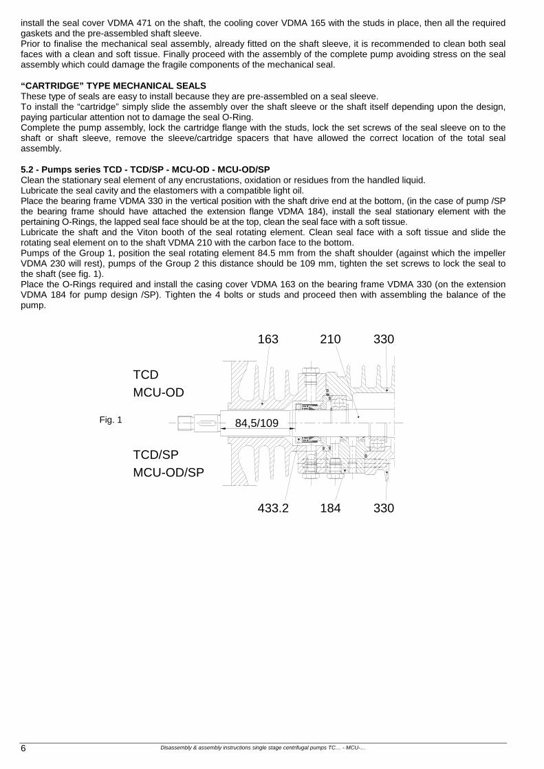
install the seal cover VDMA 471 on the shaft, the cooling cover VDMA 165 with the studs in place, then all the required gaskets and the pre-assembled shaft sleeve. Prior to finalise the mechanical seal assembly, already fitted on the shaft sleeve, it is recommended to clean both seal faces with a clean and soft tissue. Finally proceed with the assembly of the complete pump avoiding stress on the seal assembly which could damage the fragile components of the mechanical seal. “CARTRIDGE” TYPE MECHANICAL SEALS These type of seals are easy to install because they are pre-assembled on a seal sleeve. To install the “cartridge” simply slide the assembly over the shaft sleeve or the shaft itself depending upon the design, paying particular attention not to damage the seal O-Ring. Complete the pump assembly, lock the cartridge flange with the studs, lock the set screws of the seal sleeve on to the shaft or shaft sleeve, remove the sleeve/cartridge spacers that have allowed the correct location of the total seal assembly. 5.2 - Pumps series TCD - TCD/SP - MCU-OD - MCU-OD/SP Clean the stationary seal element of any encrustations, oxidation or residues from the handled liquid. Lubricate the seal cavity and the elastomers with a compatible light oil. Place the bearing frame VDMA 330 in the vertical position with the shaft drive end at the bottom, (in the case of pump /SP the bearing frame should have attached the extension flange VDMA 184), install the seal stationary element with the pertaining O-Rings, the lapped seal face should be at the top, clean the seal face with a soft tissue. Lubricate the shaft and the Viton booth of the seal rotating element. Clean seal face with a soft tissue and slide the rotating seal element on to the shaft VDMA 210 with the carbon face to the bottom. Pumps of the Group 1, position the seal rotating element 84.5 mm from the shaft shoulder (against which the impeller VDMA 230 will rest), pumps of the Group 2 this distance should be 109 mm, tighten the set screws to lock the seal to the shaft (see fig. 1). Place the O-Rings required and install the casing cover VDMA 163 on the bearing frame VDMA 330 (on the extension VDMA 184 for pump design /SP). Tighten the 4 bolts or studs and proceed then with assembling the balance of the pump.
Fig. 1
330
184 330
163 210
84,5/109
TCD
MCU-OD
TCD/SP
MCU-OD/SP
433.2
Disassembly & assembly instructions single stage centrifugal pumps TC… - MCU-… 7
6 - REPLACING THE PACKING RINGS Replacement of the packing rings can be accomplished without disassembling the pump but proceeding as follows. Remove the nuts on the packing gland studs VDMA 902.3, move the gland packing VDMA 452 as much as possible toward the drive end. Remove with a suitable tool the old packing rings VDMA 461 and the lantern ring VDMA 458. Clean the packing chamber and the shaft sleeve removing any encrustation, oxidation and deposits from the flushing fluid. Install the packing rings one by one and the lantern ring. Be sure to relocate the lantern ring in the original location and the packing rings should be rotated so that the joints are 90° apart. Replace the seal gland with the associated adjusting nuts. In the event the pump has been completely disassembled, it is recommended to fit the casing VDMA 161 with packing rings VDMA 461, lantern ring VDMA 458 and gland packing VDMA 452, then this sub-assembly will be attached to the pump frame. Be careful not to disturb the packing rings while inserting the shaft sleeve on to the shaft. Alternatively, assembly first the pump and then the stuffing box as discussed above.
7 - SPARE PARTS When ordering the pump it is good practice to also order the necessary spare parts, especially when there are no stand-by pumps in the installation. This will minimise unnecessary down times in the event of pump failure or routine maintenance. Following spare parts are suggested for each pump size:
1 Impeller 1 Wear ring 1 Shaft assembly 1 Set of bearings 1 Set of mechanical seals or packing 2 Sets of gaskets
However for proper parts management, consult the VDMA 24296 standard that recommends the quantity of spare parts to be stocked in relation to the number of pumps installed. On the pump nameplate are printed the pump model, the year of manufacture and the pump serial number: always provide this information when requesting spare parts. Specify also the VDMA number of the required part, as seen on the pump sectional drawing and parts list for proper identification of spare parts. We recommend the use of original spares: in case this is not respected, POMPETRAVAINI declines any responsability for eventual damages caused by not original spare parts.
Disassembly & assembly instructions single stage centrifugal pumps TC… - MCU-… 8
8 - SECTIONAL DRAWINGS AND TYPICAL OPTIONS
507
161102903.3
502.1
904.1
524 914561400.1
360.2
903.4 183 901.1
400.2
400.3
904
903.1230 485
940.2
925
922
433.2902.2 902.1
210
940
320330643932
421.5
935
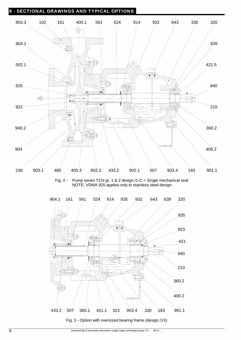
Fig. 2 - Pump series TCH gr. 1 & 2 design /1-C = Single mechanical seal NOTE: VDMA 925 applies only to stainless steel design
433.2 323507 421.1360.1
400.2
901.1903.4 183330
904.1 161 524561 914 935
360.2
210
940
421
643932 320
923
935
639
Fig. 3 - Option with oversized bearing frame (design /1X)
Disassembly & assembly instructions single stage centrifugal pumps TC… - MCU-… 9
433.2400.3
904
902.2903.1
502.1
925
230
524102 400.1903.3
639932507 400.4 903.4323 210 183 901
321
400.2
421.5
161 360.1 421.4
914
940
923
360.2
932.3 643
935
330902.1
485
940.2
Fig. 4 - Pump series TCH gr. 3 design /1-C = Single mechanical seal
230135
900.1 135.2
161
102 900.2
110 902.2904.1
400.1230
Fig. 5 - Pump series TCA - MCU-CHA (Impeller fully open)
Fig. 6 - Pump series TCT - MCU-CHT (Vortex impeller)
Disassembly & assembly instructions single stage centrifugal pumps TC… - MCU-… 10
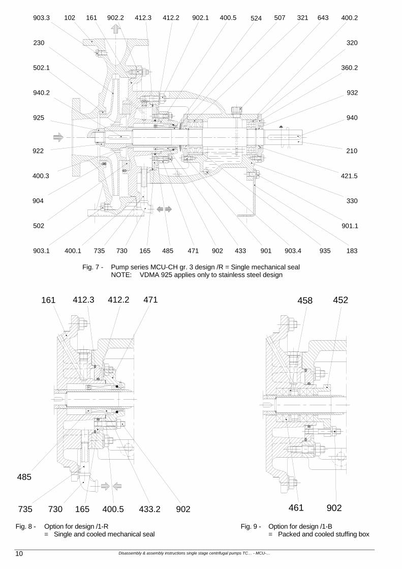
735
643 400.2
932
421.5
320
507524412.3 902.1
940
210
360.2
330
902.2102903.3
502.1
940.2
230
925
922
400.3
904
901.1
183935903.4902 901730
502
903.1 400.1
161 412.2 321
471165 485
400.5
433
Fig. 7 - Pump series MCU-CH gr. 3 design /R = Single mechanical seal NOTE: VDMA 925 applies only to stainless steel design
485
471412.3 412.2161
902735 730 400.5165 433.2
458 452
902461
Fig. 8 - Option for design /1-R = Single and cooled mechanical seal
Fig. 9 - Option for design /1-B = Packed and cooled stuffing box
Disassembly & assembly instructions single stage centrifugal pumps TC… - MCU-… 11
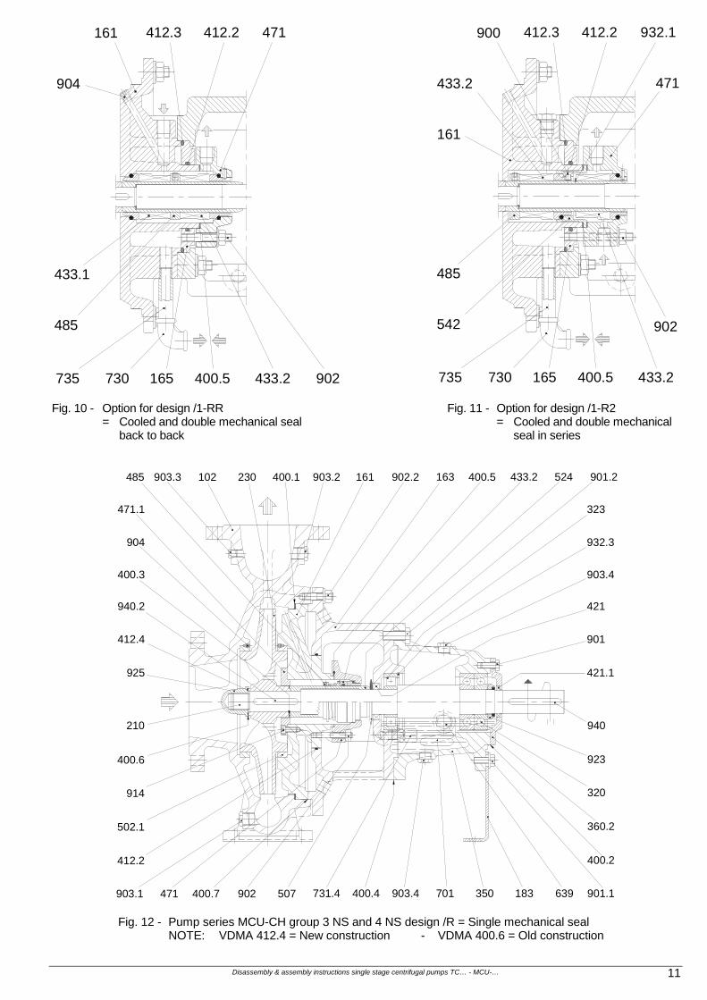
471412.3 412.2161
902
485
735 730 400.5165 433.2
433.1
904
932.1412.3 412.2900
902
735 730 400.5165 433.2
433.2
485
161
471
542
Fig. 10 - Option for design /1-RR = Cooled and double mechanical seal back to back
Fig. 11 - Option for design /1-R2 = Cooled and double mechanical seal in series
903.3 102 230 400.1 903.2 161 902.2
471.1
904
400.3
940.2
925
163
421.1
210
400.6
914
502.1
412.2
903.1 902 507 731.4 400.4 903.4 701 350 183 639 901.1
400.2
360.2
320
923
940
400.7
485
471
524 901.2
323
932.3
903.4
421
901
433.2400.5
412.4
Fig. 12 - Pump series MCU-CH group 3 NS and 4 NS design /R = Single mechanical seal NOTE: VDMA 412.4 = New construction - VDMA 400.6 = Old construction
Disassembly & assembly instructions single stage centrifugal pumps TC… - MCU-… 12
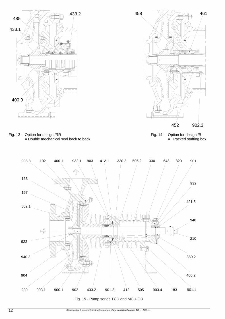
400.9
433.1
433.2485
458 461
452 902.3
Fig. 13 - Option for design /RR = Double mechanical seal back to back
Fig. 14 - Option for design /B = Packed stuffing box
903.4412 505433.2902900.1 901.2
502.1
940.2
903.1
904
230
643
922
320 901
932
940
210
360.2
183
400.2
901.1
421.5
330320.2 505.2412.1903932.1400.1102903.3
167
163
Fig. 15 - Pump series TCD and MCU-OD
Disassembly & assembly instructions single stage centrifugal pumps TC… - MCU-… 13
360.2
901.1183
400.2
932.1412.1421.1 903.4
421.5
932.1184400.1900.1102903.3
167
163
902.1433.2 903
940.2
902.2230 903.1
904
901320643
932
330320.2 505.2
940
210
502.1
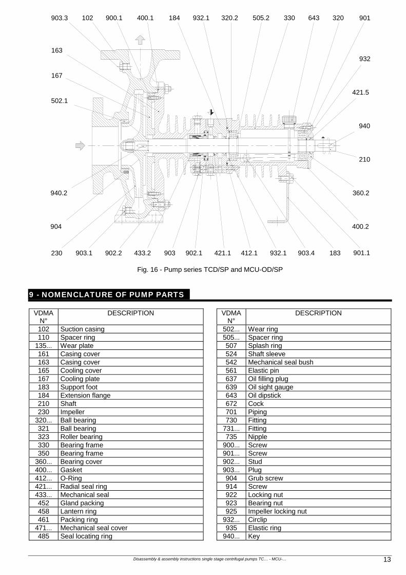
Fig. 16 - Pump series TCD/SP and MCU-OD/SP
9 - NOMENCLATURE OF PUMP PARTS
VDMA N°
DESCRIPTION VDMA N°
DESCRIPTION
102 Suction casing 502... Wear ring 110 Spacer ring 505... Spacer ring
135... Wear plate 507 Splash ring 161 Casing cover 524 Shaft sleeve 163 Casing cover 542 Mechanical seal bush 165 Cooling cover 561 Elastic pin 167 Cooling plate 637 Oil filling plug 183 Support foot 639 Oil sight gauge 184 Extension flange 643 Oil dipstick 210 Shaft 672 Cock 230 Impeller 701 Piping
320... Ball bearing 730 Fitting 321 Ball bearing 731... Fitting 323 Roller bearing 735 Nipple 330 Bearing frame 900... Screw 350 Bearing frame 901... Screw
360... Bearing cover 902... Stud 400... Gasket 903... Plug 412... O-Ring 904 Grub screw 421... Radial seal ring 914 Screw 433... Mechanical seal 922 Locking nut 452 Gland packing 923 Bearing nut 458 Lantern ring 925 Impeller locking nut 461 Packing ring 932... Circlip
471... Mechanical seal cover 935 Elastic ring 485 Seal locating ring 940... Key
Disassembly & assembly instructions single stage centrifugal pumps TC… - MCU-… 14
10 - ENGINEERING TABLES
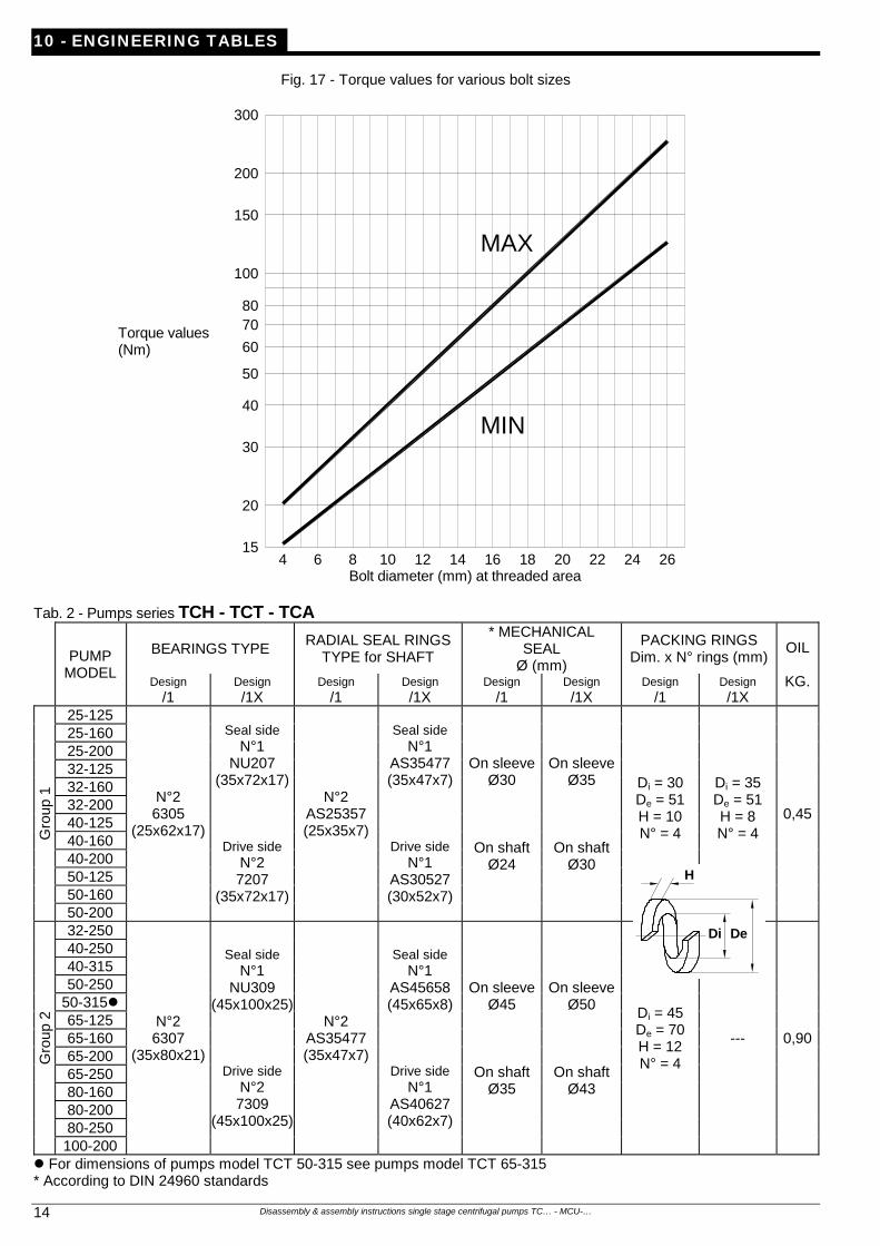
Fig. 17 - Torque values for various bolt sizes
Torque values (Nm)
300
200
100
20
50
15
30
40
60
7080
150
4 6 8 10 12 14 16 18 20 22 24 26
MAX
MIN
Bolt diameter (mm) at threaded area
Tab. 2 - Pumps series TCH - TCT - TCA
PUMP
MODEL
BEARINGS TYPE RADIAL SEAL RINGS
TYPE for SHAFT
* MECHANICAL SEAL
Ø (mm)
PACKING RINGS Dim. x N° rings (mm)
OIL
KG.Design /1
Design /1X
Design /1
Design /1X
Design /1
Design /1X
Design /1
Design /1X
Gro
up 1
25-125
N°2 6305
(25x62x17)
Seal side N°1
NU207 (35x72x17)
Drive side N°2 7207
(35x72x17)
N°2 AS25357 (25x35x7)
Seal side N°1
AS35477 (35x47x7)
Drive side N°1
AS30527 (30x52x7)
On sleeveØ30
On shaft Ø24
On sleeveØ35
On shaft Ø30
Di = 30 De = 51 H = 10 N° = 4
Di = 35 De = 51 H = 8 N° = 4
0,45
25-160 25-200 32-125 32-160 32-200 40-125 40-160 40-200 50-125 50-160 50-200
Gro
up 2
32-250
N°2 6307
(35x80x21)
Seal side N°1
NU309 (45x100x25)
Drive side N°2 7309
(45x100x25)
N°2 AS35477 (35x47x7)
Seal side N°1
AS45658 (45x65x8)
Drive side N°1
AS40627 (40x62x7)
On sleeveØ45
On shaft Ø35
On sleeveØ50
On shaft Ø43
Di = 45 De = 70 H = 12 N° = 4
--- 0,90
40-250 40-315 50-250
50-315 65-125 65-160 65-200 65-250 80-160 80-200 80-250 100-200
For dimensions of pumps model TCT 50-315 see pumps model TCT 65-315 * According to DIN 24960 standards
H
Di De
Disassembly & assembly instructions single stage centrifugal pumps TC… - MCU-… 15
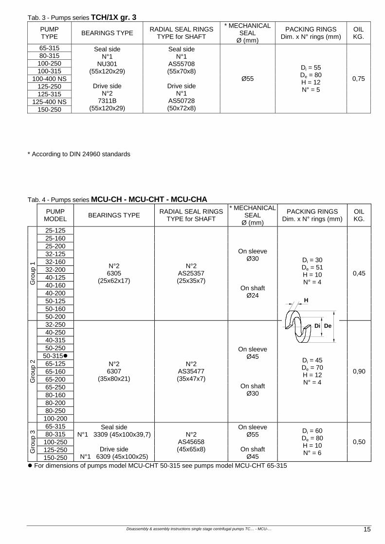
Tab. 3 - Pumps series TCH/1X gr. 3
PUMP TYPE
BEARINGS TYPE RADIAL SEAL RINGS
TYPE for SHAFT
* MECHANICAL SEAL
Ø (mm)
PACKING RINGS Dim. x N° rings (mm)
OIL KG.
65-315 80-315 100-250 100-315
100-400 NS 125-250 125-315
125-400 NS 150-250
Seal side N°1
NU301 (55x120x29)
Drive side
N°2 7311B
(55x120x29)
Seal side N°1
AS55708 (55x70x8)
Drive side
N°1 AS50728 (50x72x8)
Ø55
Di = 55 De = 80 H = 12 N° = 5
0,75
* According to DIN 24960 standards Tab. 4 - Pumps series MCU-CH - MCU-CHT - MCU-CHA
PUMP
MODEL BEARINGS TYPE
RADIAL SEAL RINGS TYPE for SHAFT
* MECHANICAL SEAL
Ø (mm)
PACKING RINGS Dim. x N° rings (mm)
OIL KG.
25-125 25-160 25-200 32-125 32-160 32-200 40-125 40-160 40-200 50-125 50-160
Gro
up 1
50-200
N°2 6305
(25x62x17)
N°2 AS25357 (25x35x7)
On sleeve Ø30
On shaft Ø24
Di = 30 De = 51 H = 10 N° = 4
0,45
32-250 40-250 40-315 50-250
50-315 65-125 65-160 65-200 65-250 80-160 80-200 80-250
Gro
up 2
100-200
N°2 6307
(35x80x21)
N°2 AS35477 (35x47x7)
On sleeve Ø45
On shaft Ø30
Di = 45 De = 70 H = 12 N° = 4
0,90
65-315 80-315 100-250 125-250 G
roup
3
150-250
Seal side N°1 3309 (45x100x39,7)
Drive side
N°1 6309 (45x100x25)
N°2 AS45658 (45x65x8)
On sleeve Ø55
On shaft
Ø45
Di = 60 De = 80 H = 10 N° = 6
0,50
For dimensions of pumps model MCU-CHT 50-315 see pumps model MCU-CHT 65-315
H
Di De
Disassembly & assembly instructions single stage centrifugal pumps TC… - MCU-… 16
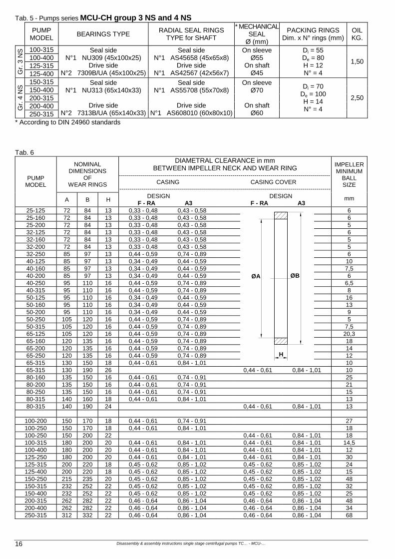
Tab. 5 - Pumps series MCU-CH group 3 NS and 4 NS
PUMP
MODEL BEARINGS TYPE
RADIAL SEAL RINGS TYPE for SHAFT
* MECHANICALSEAL
Ø (mm)
PACKING RINGS Dim. x N° rings (mm)
OIL KG.
100-315 100-400 125-315
Gr.
3 N
S
125-400
Seal side N°1 NU309 (45x100x25)
Drive side N°2 7309B/UA (45x100x25)
Seal side N°1 AS45658 (45x65x8)
Drive side N°1 AS42567 (42x56x7)
On sleeve Ø55
On shaft Ø45
Di = 55 De = 80 H = 12 N° = 4
1,50
150-315 150-400 200-315 200-400 G
r. 4
NS
250-315
Seal side N°1 NU313 (65x140x33)
Drive side
N°2 7313B/UA (65x140x33)
Seal side N°1 AS55708 (55x70x8)
Drive side
N°1 AS608010 (60x80x10)
On sleeve Ø70
On shaft
Ø60
Di = 70 De = 100 H = 14 N° = 4
2,50
* According to DIN 24960 standards Tab. 6
NOMINAL DIMENSIONS
OF WEAR RINGS
DIAMETRAL CLEARANCE in mm BETWEEN IMPELLER NECK AND WEAR RING
---------------------------------------------------------------------------------------------------------- CASING CASING COVER ----------------------------------------------------------------------------------------------------------
PUMP MODEL
A B H DESIGN DESIGN F - RA A3 F - RA A3
IMPELLERMINIMUM
BALL SIZE
mm
25-125 72 84 13 0,33 - 0,48 0,43 - 0,58 6 25-160 72 84 13 0,33 - 0,48 0,43 - 0,58 6 25-200 72 84 13 0,33 - 0,48 0,43 - 0,58 5 32-125 72 84 13 0,33 - 0,48 0,43 - 0,58 6 32-160 72 84 13 0,33 - 0,48 0,43 - 0,58 5 32-200 72 84 13 0,33 - 0,48 0,43 - 0,58 5 32-250 85 97 13 0,44 - 0,59 0,74 - 0,89 6 40-125 85 97 13 0,34 - 0,49 0,44 - 0,59 10 40-160 85 97 13 0,34 - 0,49 0,44 - 0,59 7,5 40-200 85 97 13 0,34 - 0,49 0,44 - 0,59 6 40-250 95 110 16 0,44 - 0,59 0,74 - 0,89 6,5 40-315 95 110 16 0,44 - 0,59 0,74 - 0,89 8 50-125 95 110 16 0,34 - 0,49 0,44 - 0,59 16 50-160 95 110 16 0,34 - 0,49 0,44 - 0,59 13 50-200 95 110 16 0,34 - 0,49 0,44 - 0,59 9 50-250 105 120 16 0,44 - 0,59 0,74 - 0,89 5 50-315 105 120 16 0,44 - 0,59 0,74 - 0,89 7,5 65-125 105 120 16 0,44 - 0,59 0,74 - 0,89 20,3 65-160 120 135 16 0,44 - 0,59 0,74 - 0,89 18 65-200 120 135 16 0,44 - 0,59 0,74 - 0,89 14 65-250 120 135 16 0,44 - 0,59 0,74 - 0,89 12 65-315 130 150 18 0,44 - 0,61 0,84 - 1,01 10 65-315 130 190 26 0,44 - 0,61 0,84 - 1,01 10 80-160 135 150 16 0,44 - 0,61 0,74 - 0,91 25 80-200 135 150 16 0,44 - 0,61 0,74 - 0,91 21 80-250 135 150 16 0,44 - 0,61 0,74 - 0,91 15 80-315 140 160 18 0,44 - 0,61 0,84 - 1,01 13 80-315 140 190 24 0,44 - 0,61 0,84 - 1,01 13
100-200 150 170 18 0,44 - 0,61 0,74 - 0,91 27 100-250 150 170 18 0,44 - 0,61 0,84 - 1,01 18 100-250 150 200 22 0,44 - 0,61 0,84 - 1,01 18 100-315 180 200 20 0,44 - 0,61 0,84 - 1,01 0,44 - 0,61 0,84 - 1,01 14,5 100-400 180 200 20 0,44 - 0,61 0,84 - 1,01 0,44 - 0,61 0,84 - 1,01 12 125-250 180 200 20 0,44 - 0,61 0,84 - 1,01 0,44 - 0,61 0,84 - 1,01 30 125-315 200 220 18 0,45 - 0,62 0,85 - 1,02 0,45 - 0,62 0,85 - 1,02 24 125-400 200 220 18 0,45 - 0,62 0,85 - 1,02 0,45 - 0,62 0,85 - 1,02 15 150-250 215 235 20 0,45 - 0,62 0,85 - 1,02 0,45 - 0,62 0,85 - 1,02 48 150-315 232 252 22 0,45 - 0,62 0,85 - 1,02 0,45 - 0,62 0,85 - 1,02 32 150-400 232 252 22 0,45 - 0,62 0,85 - 1,02 0,45 - 0,62 0,85 - 1,02 25 200-315 262 282 22 0,46 - 0,64 0,86 - 1,04 0,46 - 0,64 0,86 - 1,04 48 200-400 262 282 22 0,46 - 0,64 0,86 - 1,04 0,46 - 0,64 0,86 - 1,04 34 250-315 312 332 22 0,46 - 0,64 0,86 - 1,04 0,46 - 0,64 0,86 - 1,04 68
H
ØA ØB

Disassembly & assembly instructions single stage centrifugal pumps TC… - MCU-… 17
(Blank page)

Disassembly & assembly instructions single stage centrifugal pumps TC… - MCU-… 18
(Blank page)
Disassembly & assembly instructions single stage centrifugal pumps TC… - MCU-… 19
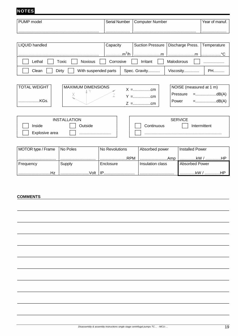
NOTES
PUMP model .........................................................................
Serial Number ......................
Computer Number ........................................................
Year of manuf. ......................
LIQUID handled .........................................................................
Capacity ...............m3/h
Suction Pressure ........................m
Discharge Press. ........................m
Temperature
..................°C
Lethal Toxic Noxious Corrosive Irritant Malodorous ...................
Clean Dirty With suspended parts Spec. Gravity........... Viscosity.............. PH..........
TOTAL WEIGHT ...................KGs.
MAXIMUM DIMENSIONS
X =................cm
Y =................cm
Z =................cm
NOISE (measured at 1 m)
Pressure =...................dB(A)
Power =...................dB(A)
INSTALLATION SERVICE
Inside Outside Continuous Intermittent
Explosive area ............................. ......................................................................
MOTOR type / Frame ..................................
No Poles ................................
No Revolutions ........................RPM
Absorbed power .........................Amp
Installed Power ...............kW / ..............HP
Frequency .............................Hz
Supply ..........................Volt
Enclosure IP............................
Insulation class ...............................
Absorbed Power ..............kW / ..............HP
COMMENTS
Disassembly & assembly instructions single stage centrifugal pumps TC… - MCU-… 20
OUR PRODUCTION
MONOSTAGE CENTRIFUGAL PUMPS
MAGNETIC DRIVE MONOSTAGE CENTRIFUGAL PUMPS
SELF-PRIMING CENTRIFUGAL PUMPS
MAGNETIC DRIVE
SELF-PRIMING CENTRIFUGAL PUMPS
MULTISTAGE CENTRIFUGAL PUMPS
LIQUID RING VACUUM PUMPS
LIQUID RING COMPRESSORS
PACKAGE VACUUM UNITS WITH PARTIAL OR TOTAL SERVICE LIQUID RECIRCULATION
NA5.SM.TCH0.GB00 / PRINTED IN ITALY Smontaggio TC… - MCU-… Inglese
POMPETRAVAINI’S continuing research results in product improvement, therefore any specifications may be subject to change without notice.
S.p.A.
20022 CASTANO PRIMO (Milano) ITALY Via per Turbigo, 44 – Zona Industriale Tel. 0331 889000 – Fax 0331 889090 www.pompetravaini.it