dionex ics-2100 ion chromatography system operator's...
TRANSCRIPT
Dionex ICS-2100 Ion Chromatography System Operator’s Manual
Document No. 065291Revision 03
October 2012
© 2012 by Thermo Fisher Scientific Inc. All rights reserved.
AES, AMMS ICE, ASRS, Chromeleon, Dionex, IonPac, OnGuard, and SRS are registered trademarks of Thermo Fisher Scientific Inc. in the United States.
Microsoft, Windows, Windows 2000, and Windows XP are registered trademarks of Microsoft Corporation in the United States and other countries. Adobe, Acrobat, and Adobe Reader are registered trademarks of Adobe Systems, Incorporated in the United States and other countries.
Reagent-Free and RFIC are trademarks of Thermo Fisher Scientific Inc.
PEEK is a trademark of Victrex PLC.
All other trademarks are the property of Thermo Fisher Scientific Inc. and its subsidiaries.
Thermo Fisher Scientific Inc. provides this document to its customers with a product purchase to use in the product operation. This document is copyright protected and any reproduction of the whole or any part of this document is strictly prohibited, except with the written authorization of Thermo Fisher Scientific Inc.
The contents of this document are subject to change without notice. All technical information in this document is for reference purposes only. System configurations and specifications in this document supersede all previous information received by the purchaser.
Thermo Fisher Scientific Inc. makes no representations that this document is complete, accurate or error-free and assumes no responsibility and will not be liable for any errors, omissions, damage or loss that might result from any use of this document, even if the information in the document is followed properly.
This document is not part of any sales contract between Thermo Fisher Scientific Inc. and a purchaser. This document shall in no way govern or modify any Terms and Conditions of Sale, which Terms and Conditions of Sale shall govern all conflicting information between the two documents.
Revision history: Revision 01 released March 2009; initial release of systemRevision 02 released December 2011; Thermo Fisher Scientific transitionRevision 03 released October 2012; new part numbers assigned
For Research Use Only. Not for use in diagnostic procedures.
Doc. 065291-03 10/12 i
1 • Introduction . . . . . . . . . . . . . . . . . . . . . . . . . . . . . . . . . . . . . . . . . . . . . . 1
1.1 Introduction to Ion Chromatography (IC) . . . . . . . . . . . . . . . . . . . . . . . . 1
1.2 Overview of the Dionex ICS-2100 . . . . . . . . . . . . . . . . . . . . . . . . . . . . . 4
1.3 About This Manual . . . . . . . . . . . . . . . . . . . . . . . . . . . . . . . . . . . . . . . . . 5
1.3.1 Safety Messages and Notes . . . . . . . . . . . . . . . . . . . . . . . . . . . . 6
1.4 Safety and Regulatory Information . . . . . . . . . . . . . . . . . . . . . . . . . . . . . 8
1.4.1 Safety Labels . . . . . . . . . . . . . . . . . . . . . . . . . . . . . . . . . . . . . . . 8
2 • Features . . . . . . . . . . . . . . . . . . . . . . . . . . . . . . . . . . . . . . . . . . . . . . . . . . 11
2.1 Operating Features . . . . . . . . . . . . . . . . . . . . . . . . . . . . . . . . . . . . . . . . . 11
2.1.1 Front Panel . . . . . . . . . . . . . . . . . . . . . . . . . . . . . . . . . . . . . . . . 11
2.1.2 Top Cover . . . . . . . . . . . . . . . . . . . . . . . . . . . . . . . . . . . . . . . . . 16
2.1.3 Component Panel . . . . . . . . . . . . . . . . . . . . . . . . . . . . . . . . . . . 18
2.1.4 Rear Panel . . . . . . . . . . . . . . . . . . . . . . . . . . . . . . . . . . . . . . . . . 21
2.2 Flow Schematics . . . . . . . . . . . . . . . . . . . . . . . . . . . . . . . . . . . . . . . . . . 23
2.3 Chromeleon and Chromeleon Xpress . . . . . . . . . . . . . . . . . . . . . . . . . . 30
2.3.1 The Panel Tabset . . . . . . . . . . . . . . . . . . . . . . . . . . . . . . . . . . . 30
2.3.2 Software Control Modes . . . . . . . . . . . . . . . . . . . . . . . . . . . . . 31
2.3.3 System Wellness . . . . . . . . . . . . . . . . . . . . . . . . . . . . . . . . . . . . 31
2.4 System Component Details . . . . . . . . . . . . . . . . . . . . . . . . . . . . . . . . . . 32
2.4.1 Vacuum Degas Assembly (Optional) . . . . . . . . . . . . . . . . . . . . 32
Contents
Dionex ICS-2100 Ion Chromatography System
ii Doc. 065291-03 10/12
2.4.2 Eluent Valve . . . . . . . . . . . . . . . . . . . . . . . . . . . . . . . . . . . . . . .34
2.4.3 Pump . . . . . . . . . . . . . . . . . . . . . . . . . . . . . . . . . . . . . . . . . . . . .34
2.4.4 Eluent Generator . . . . . . . . . . . . . . . . . . . . . . . . . . . . . . . . . . . .37
2.4.5 Auxiliary Power Supply (Optional) . . . . . . . . . . . . . . . . . . . . . .42
2.4.6 Injection Valve . . . . . . . . . . . . . . . . . . . . . . . . . . . . . . . . . . . . .42
2.4.7 Auxiliary Valve (Optional) . . . . . . . . . . . . . . . . . . . . . . . . . . . .44
2.4.8 Column Heater . . . . . . . . . . . . . . . . . . . . . . . . . . . . . . . . . . . . . .45
2.4.9 Suppressor . . . . . . . . . . . . . . . . . . . . . . . . . . . . . . . . . . . . . . . . .46
2.4.10 DS6 Heated Conductivity Cell . . . . . . . . . . . . . . . . . . . . . . . . .46
3 • Operation and Maintenance . . . . . . . . . . . . . . . . . . . . . . . .49
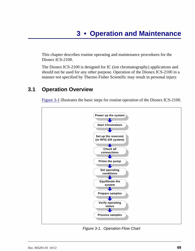
3.1 Operation Overview . . . . . . . . . . . . . . . . . . . . . . . . . . . . . . . . . . . . . . . .49
3.2 Turning On the System Power . . . . . . . . . . . . . . . . . . . . . . . . . . . . . . . .51
3.3 Connecting to Chromeleon . . . . . . . . . . . . . . . . . . . . . . . . . . . . . . . . . . .52
3.4 Set Up the Eluent Reservoir . . . . . . . . . . . . . . . . . . . . . . . . . . . . . . . . . .54
3.4.1 Filter the Deionized Water . . . . . . . . . . . . . . . . . . . . . . . . . . . .54
3.4.2 Fill the Reservoir . . . . . . . . . . . . . . . . . . . . . . . . . . . . . . . . . . . .54
3.4.3 Set the Eluent Level . . . . . . . . . . . . . . . . . . . . . . . . . . . . . . . . . .54
3.4.4 Connect the Reservoir . . . . . . . . . . . . . . . . . . . . . . . . . . . . . . . .56
3.5 Check All Connections . . . . . . . . . . . . . . . . . . . . . . . . . . . . . . . . . . . . . .57
3.6 Prime the Pump . . . . . . . . . . . . . . . . . . . . . . . . . . . . . . . . . . . . . . . . . . .57
3.7 Set System Operating Conditions . . . . . . . . . . . . . . . . . . . . . . . . . . . . . .58
3.8 Equilibrate the System and Verify Operational Status . . . . . . . . . . . . .59
Contents
Doc. 065291-03 10/12 iii
3.9 Prepare Samples . . . . . . . . . . . . . . . . . . . . . . . . . . . . . . . . . . . . . . . . . . 60
3.9.1 Collecting and Storing Samples . . . . . . . . . . . . . . . . . . . . . . . . 60
3.9.2 Pretreating Samples . . . . . . . . . . . . . . . . . . . . . . . . . . . . . . . . . 61
3.9.3 Diluting Samples . . . . . . . . . . . . . . . . . . . . . . . . . . . . . . . . . . . 61
3.10 Loading and Injecting Samples . . . . . . . . . . . . . . . . . . . . . . . . . . . . . . . 62
3.10.1 Loading Samples with a Syringe . . . . . . . . . . . . . . . . . . . . . . . 63
3.10.2 Loading Samples with a Vacuum Syringe . . . . . . . . . . . . . . . . 64
3.10.3 Loading Samples with an Autosampler . . . . . . . . . . . . . . . . . . 64
3.10.4 Injecting Samples . . . . . . . . . . . . . . . . . . . . . . . . . . . . . . . . . . . 65
3.11 Processing Samples . . . . . . . . . . . . . . . . . . . . . . . . . . . . . . . . . . . . . . . . 65
3.11.1 Manual Sample Processing . . . . . . . . . . . . . . . . . . . . . . . . . . . 65
3.11.2 Automatic (Batch) Sample Processing . . . . . . . . . . . . . . . . . . . 66
3.12 Maintenance . . . . . . . . . . . . . . . . . . . . . . . . . . . . . . . . . . . . . . . . . . . . . 68
4 • Troubleshooting . . . . . . . . . . . . . . . . . . . . . . . . . . . . . . . . . . . . . . . 71
4.1 Error Messages . . . . . . . . . . . . . . . . . . . . . . . . . . . . . . . . . . . . . . . . . . . 71
4.2 Troubleshooting Error Messages . . . . . . . . . . . . . . . . . . . . . . . . . . . . . . 74
4.3 Liquid Leaks . . . . . . . . . . . . . . . . . . . . . . . . . . . . . . . . . . . . . . . . . . . . . 86
4.4 Pump Difficult to Prime or Loses Prime . . . . . . . . . . . . . . . . . . . . . . . . 88
4.5 Pump Does Not Start . . . . . . . . . . . . . . . . . . . . . . . . . . . . . . . . . . . . . . . 90
4.6 No Flow . . . . . . . . . . . . . . . . . . . . . . . . . . . . . . . . . . . . . . . . . . . . . . . . . 90
4.7 Erratic Flow/Pressure Reading . . . . . . . . . . . . . . . . . . . . . . . . . . . . . . . 91
4.8 Excessive System Backpressure . . . . . . . . . . . . . . . . . . . . . . . . . . . . . . 92
4.9 Peak “Ghosting” . . . . . . . . . . . . . . . . . . . . . . . . . . . . . . . . . . . . . . . . . . 93
Dionex ICS-2100 Ion Chromatography System
iv Doc. 065291-03 10/12
4.10 Nonreproducible Peak Height or Retention Time . . . . . . . . . . . . . . . . .94
4.11 Abnormal Retention Time or Selectivity . . . . . . . . . . . . . . . . . . . . . . . .94
4.12 No Cell Response . . . . . . . . . . . . . . . . . . . . . . . . . . . . . . . . . . . . . . . . . .94
4.13 High Cell Output . . . . . . . . . . . . . . . . . . . . . . . . . . . . . . . . . . . . . . . . . .95
4.14 Baseline Noise or Drift . . . . . . . . . . . . . . . . . . . . . . . . . . . . . . . . . . . . . .96
4.15 Vacuum Degas Assembly Does Not Run . . . . . . . . . . . . . . . . . . . . . . . .97
5 • Service . . . . . . . . . . . . . . . . . . . . . . . . . . . . . . . . . . . . . . . . . . . . . . . . . . . .99
5.1 Diagnostic and Calibration Procedures . . . . . . . . . . . . . . . . . . . . . . . . .99
5.1.1 Chromeleon Wellness Panel Overview . . . . . . . . . . . . . . . . . .100
5.1.2 Diagnostic and Calibration Touch Screen Overview . . . . . . .102
5.1.3 Calibrating the Conductivity Cell . . . . . . . . . . . . . . . . . . . . . .103
5.1.4 Calibrating the Flow Rate . . . . . . . . . . . . . . . . . . . . . . . . . . . .106
5.1.5 Calibrating the Vacuum Degas Assembly . . . . . . . . . . . . . . . .108
5.2 Isolating a Restriction in the Liquid Lines . . . . . . . . . . . . . . . . . . . . . .109
5.3 Replacing Tubing and Fittings . . . . . . . . . . . . . . . . . . . . . . . . . . . . . . .113
5.4 Rebuilding the Injection Valve or Auxiliary Valve . . . . . . . . . . . . . . .114
5.5 Replacing an Auxiliary Valve Pod . . . . . . . . . . . . . . . . . . . . . . . . . . . .115
5.6 Cleaning and Replacing the Pump Check Valves . . . . . . . . . . . . . . . .118
5.7 Replacing a Pump Piston Seal and Piston Rinse Seal . . . . . . . . . . . . .120
5.8 Replacing a Pump Piston . . . . . . . . . . . . . . . . . . . . . . . . . . . . . . . . . . .124
5.9 Replacing the Waste Valve or Priming Valve O-Ring . . . . . . . . . . . . .125
5.10 Replacing the Conductivity Cell . . . . . . . . . . . . . . . . . . . . . . . . . . . . . .127
5.11 Replacing the Suppressor . . . . . . . . . . . . . . . . . . . . . . . . . . . . . . . . . . .130
Contents
Doc. 065291-03 10/12 v
5.12 Replacing the Column Heater . . . . . . . . . . . . . . . . . . . . . . . . . . . . . . . 131
5.13 Replacing the Column Heater Heat Exchanger . . . . . . . . . . . . . . . . . . 134
5.14 Replacing the Eluent Valve . . . . . . . . . . . . . . . . . . . . . . . . . . . . . . . . . 135
5.15 Replacing the Leak Sensor . . . . . . . . . . . . . . . . . . . . . . . . . . . . . . . . . 137
5.16 Priming the Pump . . . . . . . . . . . . . . . . . . . . . . . . . . . . . . . . . . . . . . . . 138
5.16.1 Priming the Eluent Lines with a Syringe . . . . . . . . . . . . . . . . 138
5.16.2 Priming with the Prime Button . . . . . . . . . . . . . . . . . . . . . . . . 140
5.17 Priming the Pump with Isopropyl Alcohol . . . . . . . . . . . . . . . . . . . . . 141
5.18 Changing Main Power Fuses . . . . . . . . . . . . . . . . . . . . . . . . . . . . . . . . 142
5.19 Replacing a Dionex EluGen Cartridge . . . . . . . . . . . . . . . . . . . . . . . . 143
5.19.1 Replacing a KOH, LiOH, MSA, or NaOH
Dionex EluGen Cartridge . . . . . . . . . . . . . . . . . . . . . . . . . . . . 143
5.19.2 Replacing a K2CO3 Cartridge . . . . . . . . . . . . . . . . . . . . . . . . 151
5.20 Replacing the CR-TC . . . . . . . . . . . . . . . . . . . . . . . . . . . . . . . . . . . . . 165
5.21 Replacing the EPM Electrolytic pH Modifier . . . . . . . . . . . . . . . . . . . 169
5.21.1 Recording the EPM Serial Number in Chromeleon . . . . . . . . 170
5.21.2 Plumbing the EPM for Hydrating and Conditioning . . . . . . . 171
5.21.3 Hydrating and Conditioning the EPM . . . . . . . . . . . . . . . . . . 173
5.22 Replacing the EGC CO3 Mixer . . . . . . . . . . . . . . . . . . . . . . . . . . . . . . 174
5.22.1 Installing the New EGC CO3 Mixer . . . . . . . . . . . . . . . . . . . 174
5.22.2 Filling the EGC CO3 Mixer with Deionized Water . . . . . . . . 175
5.22.3 Filling the EGC CO3 Mixer with Eluent . . . . . . . . . . . . . . . . 178
5.23 Replacing the EGC Holder and Degas Assembly . . . . . . . . . . . . . . . . 185
5.23.1 Disconnecting and Removing the Dionex EluGen
Cartridge . . . . . . . . . . . . . . . . . . . . . . . . . . . . . . . . . . . . . . . . . 185
Dionex ICS-2100 Ion Chromatography System
vi Doc. 065291-03 10/12
5.23.2 Removing the CR-TC and Reinstalling it in the New EGC
Holder . . . . . . . . . . . . . . . . . . . . . . . . . . . . . . . . . . . . . . . . . . .188
5.23.3 Removing the EPM and Reinstalling it in the New EGC
Holder . . . . . . . . . . . . . . . . . . . . . . . . . . . . . . . . . . . . . . . . . . .190
5.23.4 Installing the New EGC Holder Without a CR-TC or EPM . .192
5.23.5 Reinstalling the Dionex EluGen Cartridge . . . . . . . . . . . . . . .193
A • Specifications . . . . . . . . . . . . . . . . . . . . . . . . . . . . . . . . . . . . . . . . .195
A.1 Electrical . . . . . . . . . . . . . . . . . . . . . . . . . . . . . . . . . . . . . . . . . . . . . . . .195
A.2 Physical . . . . . . . . . . . . . . . . . . . . . . . . . . . . . . . . . . . . . . . . . . . . . . . . .195
A.3 Environmental . . . . . . . . . . . . . . . . . . . . . . . . . . . . . . . . . . . . . . . . . . .196
A.4 Front Panel . . . . . . . . . . . . . . . . . . . . . . . . . . . . . . . . . . . . . . . . . . . . . .196
A.5 Analytical Pump and Fluidics . . . . . . . . . . . . . . . . . . . . . . . . . . . . . . . .196
A.6 Eluent Generation . . . . . . . . . . . . . . . . . . . . . . . . . . . . . . . . . . . . . . . . .198
A.7 Detector Electronics . . . . . . . . . . . . . . . . . . . . . . . . . . . . . . . . . . . . . . .200
A.8 Conductivity Cell with Heat Exchanger . . . . . . . . . . . . . . . . . . . . . . . .200
A.9 Injection Valve . . . . . . . . . . . . . . . . . . . . . . . . . . . . . . . . . . . . . . . . . . .201
A.10 Auxiliary Valve (Optional) . . . . . . . . . . . . . . . . . . . . . . . . . . . . . . . . . .201
A.11 Vacuum Degas Assembly . . . . . . . . . . . . . . . . . . . . . . . . . . . . . . . . . . .201
A.12 Column Heater . . . . . . . . . . . . . . . . . . . . . . . . . . . . . . . . . . . . . . . . . . .201
A.13 Auxiliary Power Supply (Optional) . . . . . . . . . . . . . . . . . . . . . . . . . . .202
A.14 Suppressors . . . . . . . . . . . . . . . . . . . . . . . . . . . . . . . . . . . . . . . . . . . . . .202
A.15 Autosampler . . . . . . . . . . . . . . . . . . . . . . . . . . . . . . . . . . . . . . . . . . . . .203
A.16 System Software . . . . . . . . . . . . . . . . . . . . . . . . . . . . . . . . . . . . . . . . . .204
Contents
Doc. 065291-03 10/12 vii
B • Touch Screen Operation. . . . . . . . . . . . . . . . . . . . . . . . . . . 207
B.1 Using the Touch Screen . . . . . . . . . . . . . . . . . . . . . . . . . . . . . . . . . . . . 207
B.2 Using the Touch Screen with Chromeleon . . . . . . . . . . . . . . . . . . . . . 210
B.3 Overview of Dionex ICS-2100 Touch Screen Pages . . . . . . . . . . . . . 211
B.4 Home Page . . . . . . . . . . . . . . . . . . . . . . . . . . . . . . . . . . . . . . . . . . . . . . 212
B.4.1 Home Page Pump Controls . . . . . . . . . . . . . . . . . . . . . . . . . . 212
B.4.2 Home Page EGC Controls . . . . . . . . . . . . . . . . . . . . . . . . . . . 214
B.4.3 Home Page Column Heater . . . . . . . . . . . . . . . . . . . . . . . . . . 214
B.4.4 Home Page Injection Valve Controls . . . . . . . . . . . . . . . . . . . 215
B.4.5 Home Page Detector Controls . . . . . . . . . . . . . . . . . . . . . . . . 215
B.4.6 Other Home Page Controls . . . . . . . . . . . . . . . . . . . . . . . . . . . 216
B.5 Plot Page . . . . . . . . . . . . . . . . . . . . . . . . . . . . . . . . . . . . . . . . . . . . . . . 217
B.6 Status Page . . . . . . . . . . . . . . . . . . . . . . . . . . . . . . . . . . . . . . . . . . . . . . 218
B.6.1 Viewing Other Status Parameters . . . . . . . . . . . . . . . . . . . . . . 220
B.6.2 Status Parameter Details . . . . . . . . . . . . . . . . . . . . . . . . . . . . . 221
B.7 Pump Page . . . . . . . . . . . . . . . . . . . . . . . . . . . . . . . . . . . . . . . . . . . . . . 223
B.7.1 Setting Pump Pressure Limits and Selecting the Pressure
Unit . . . . . . . . . . . . . . . . . . . . . . . . . . . . . . . . . . . . . . . . . . . . . 223
B.7.2 Setting Degas Operating Parameters (Optional) . . . . . . . . . . 224
B.7.3 Controlling the Eluent Valve . . . . . . . . . . . . . . . . . . . . . . . . . 225
B.8 Eluent Generator Page . . . . . . . . . . . . . . . . . . . . . . . . . . . . . . . . . . . . . 226
B.8.1 EGC Serial Number . . . . . . . . . . . . . . . . . . . . . . . . . . . . . . . . 226
B.8.2 Setting the Eluent Concentration . . . . . . . . . . . . . . . . . . . . . . 227
B.8.3 Controlling the Eluent Generator Power . . . . . . . . . . . . . . . . 228
Dionex ICS-2100 Ion Chromatography System
viii Doc. 065291-03 10/12
B.8.4 Monitoring the EluGen Cartridge Life . . . . . . . . . . . . . . . . . .228
B.8.5 Controlling the CR-TC Power . . . . . . . . . . . . . . . . . . . . . . . . .229
B.9 Suppressor Page . . . . . . . . . . . . . . . . . . . . . . . . . . . . . . . . . . . . . . . . . .230
B.10 Detector Page . . . . . . . . . . . . . . . . . . . . . . . . . . . . . . . . . . . . . . . . . . . .231
B.10.1 Setting the Data Rise Time . . . . . . . . . . . . . . . . . . . . . . . . . . .232
B.10.2 Selecting the Conductivity Polarity . . . . . . . . . . . . . . . . . . . . .232
B.10.3 Setting Analog Out Options . . . . . . . . . . . . . . . . . . . . . . . . . .233
B.11 Information Page . . . . . . . . . . . . . . . . . . . . . . . . . . . . . . . . . . . . . . . . .234
B.12 Module Setup Page . . . . . . . . . . . . . . . . . . . . . . . . . . . . . . . . . . . . . . . .235
B.13 Input/Output Page . . . . . . . . . . . . . . . . . . . . . . . . . . . . . . . . . . . . . . . . .236
B.14 Diagnostic and Calibration Pages . . . . . . . . . . . . . . . . . . . . . . . . . . . . .236
C • TTL and Relay Control . . . . . . . . . . . . . . . . . . . . . . . . . . . . . .239
C.1 TTL and Relay Connections . . . . . . . . . . . . . . . . . . . . . . . . . . . . . . . . .239
C.1.1 Selecting TTL Input Functions and Control Types . . . . . . . . .242
C.2 Controlling TTL and Relay Outputs . . . . . . . . . . . . . . . . . . . . . . . . . . .245
C.3 Example Setup for Stand-Alone Operation . . . . . . . . . . . . . . . . . . . . .246
D • Reordering Information. . . . . . . . . . . . . . . . . . . . . . . . . . . . .251
E • FAQ . . . . . . . . . . . . . . . . . . . . . . . . . . . . . . . . . . . . . . . . . . . . . . . . . . . . . . .255
E.1 How do I hook up an autosampler? . . . . . . . . . . . . . . . . . . . . . . . . . . .255
E.2 How do I print? . . . . . . . . . . . . . . . . . . . . . . . . . . . . . . . . . . . . . . . . . . .255
E.3 Why are the retention times moving? . . . . . . . . . . . . . . . . . . . . . . . . . .255
Contents
Doc. 065291-03 10/12 ix
E.4 How do I adjust retention times? . . . . . . . . . . . . . . . . . . . . . . . . . . . . . 255
E.5 When should I remake standards? . . . . . . . . . . . . . . . . . . . . . . . . . . . . 255
E.6 When should I replace the eluent generator cartridge? . . . . . . . . . . . 256
E.7 How do I start Chromeleon? . . . . . . . . . . . . . . . . . . . . . . . . . . . . . . . . 256
E.8 How do I delete data? . . . . . . . . . . . . . . . . . . . . . . . . . . . . . . . . . . . . . 256
E.9 How do I back up data? . . . . . . . . . . . . . . . . . . . . . . . . . . . . . . . . . . . . 256
E.10 How do I shut off the system? . . . . . . . . . . . . . . . . . . . . . . . . . . . . . . . 256
E.11 How do I store columns? . . . . . . . . . . . . . . . . . . . . . . . . . . . . . . . . . . . 256
E.12 How do I know when a column is dirty? . . . . . . . . . . . . . . . . . . . . . . . 257
E.13 How do I clean a column? . . . . . . . . . . . . . . . . . . . . . . . . . . . . . . . . . . 257
E.14 Why is the conductivity high? . . . . . . . . . . . . . . . . . . . . . . . . . . . . . . . 257
E.15 How do I configure and operate the auxiliary valve? . . . . . . . . . . . . . 257
F • Glossary . . . . . . . . . . . . . . . . . . . . . . . . . . . . . . . . . . . . . . . . . . . . . . . . 259
Index
Dionex ICS-2100 Ion Chromatography System
x Doc. 065291-03 10/12
Doc. 065291-03 10/12 1
1 • Introduction
1.1 Introduction to Ion Chromatography (IC)
The Thermo Scientific Dionex™ ICS-2100 Ion Chromatography System (Dionex ICS-2100) performs ion analyses using suppressed or non-suppressed conductivity detection. An ion chromatography system typically consists of a liquid eluent, a high-pressure pump, a sample injector, a guard and separator column, a chemical suppressor, a conductivity cell, and a data collection system.
Before running a sample, the ion chromatography system is calibrated using a standard solution. By comparing the data obtained from a sample to that obtained from the known standard, sample ions can be identified and quantitated. The data collection system, typically a computer running chromatography software, produces a chromatogram (a plot of the detector output vs. time). The chromatography software converts each peak in the chromatogram to a sample concentration and produces a printout of the results.
Dionex ICS-2100 Ion Chromatography System
2 Doc. 065291-03 10/12
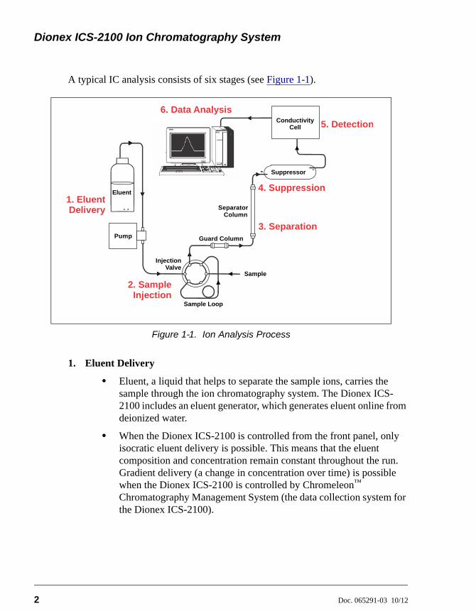
A typical IC analysis consists of six stages (see Figure 1-1).
1. Eluent Delivery
• Eluent, a liquid that helps to separate the sample ions, carries the sample through the ion chromatography system. The Dionex ICS-2100 includes an eluent generator, which generates eluent online from deionized water.
• When the Dionex ICS-2100 is controlled from the front panel, only isocratic eluent delivery is possible. This means that the eluent composition and concentration remain constant throughout the run. Gradient delivery (a change in concentration over time) is possible when the Dionex ICS-2100 is controlled by Chromeleon™ Chromatography Management System (the data collection system for the Dionex ICS-2100).
Figure 1-1. Ion Analysis Process
Guard Column
Separator Column
Pump
ConductivityCell
InjectionValve
Suppressor
1. Eluent Delivery
3. Separation
5. Detection
6. Data Analysis
Sample Loop
Sample
Eluent4. Suppression
2. Sample Injection
1 • Introduction
Doc. 065291-03 10/12 3
2. Sample Injection
• The liquid sample is loaded into a sample loop either manually or automatically (if an automated sampler is installed). When triggered, the Dionex ICS-2100 injects the sample into the eluent stream.
• The pump pushes the eluent and sample through the guard and separator columns (chemically-inert tubes packed with a polymeric resin). The guard column removes contaminants that might poison the separator column.
3. Separation
• As the eluent and sample are pumped through the separator column, the sample ions are separated. In the Dionex ICS-2100, the mode of separation is called ion exchange. This is based on the premise that different sample ions migrate through the IC column at different rates, depending upon their interactions with the ion exchange sites.
4. Suppression
• After the eluent and sample ions leave the column, they flow through a suppressor that selectively enhances detection of the sample ions while suppressing the conductivity of the eluent.
5. Detection
• A conductivity cell measures the electrical conductance of the sample ions as they emerge from the suppressor and produces a signal based on a chemical or physical property of the analyte.
6. Data Analysis
• The conductivity cell transmits the signal to a data collection system.
• The data collection system (for the Dionex ICS-2100, this is the Chromeleon™ Chromatography Management System) identifies the ions based on retention time, and quantifies each analyte by integrating the peak area or peak height. The data is quantitated by comparing the sample peaks in a chromatogram to those produced from a standard solution. The results are displayed as a chromatogram and the concentrations of ionic analytes can be automatically determined and tabulated.
Dionex ICS-2100 Ion Chromatography System
4 Doc. 065291-03 10/12
1.2 Overview of the Dionex ICS-2100
The Dionex ICS-2100 is an integrated ion chromatography system containing an eluent generator, pump, injection valve, column heater, and conductivity detector. Other system components, including a guard column, separator column, and suppressor vary, depending on the analyses to be performed.
The Dionex ICS-2100 can be configured with a vacuum degas assembly for online eluent degassing. If desired, the second eluent generator power supply can be configured to power an auxiliary electrolytic device, such as a water purifier.
An optional second high-pressure valve (6-port or 10-port) can be installed for sample preparation applications.
Dionex ICS-2100 operation can be controlled in one of two ways:
• Remotely, with a personal computer running Microsoft® Windows® Vista or Windows XP and Chromeleon software (version 6.80 SR6a or later). Chromeleon also provides data acquisition and data processing functions.
• Locally, with the front panel LCD touch screen. The touch screen is used for instrument control only. It does not provide data acquisition or data processing functions. An analog output on the rear panel can be connected to a separate data acquisition device.
For communication between the Dionex ICS-2100 and Chromeleon, the Dionex ICS-2100 is connected to a USB (Universal Serial Bus) port on the computer or a USB hub. For details, see the Dionex ICS-2100 installation instructions. Also refer to Installing the Chromeleon Chromatography Management System with a Dionex Ion Chromatograph (IC) (Document No. 031883).
1 • Introduction
Doc. 065291-03 10/12 5
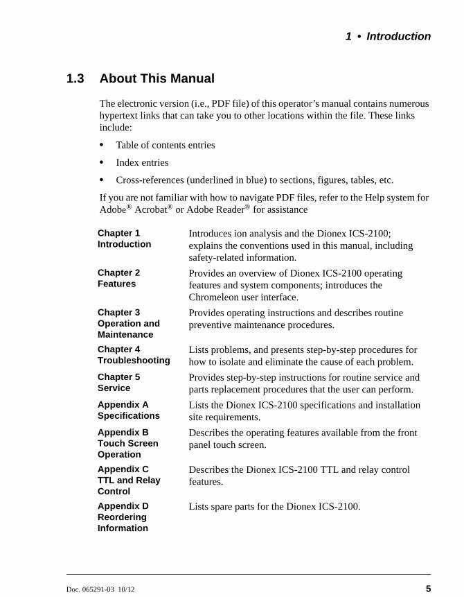
1.3 About This Manual
The electronic version (i.e., PDF file) of this operator’s manual contains numerous hypertext links that can take you to other locations within the file. These links include:
• Table of contents entries
• Index entries
• Cross-references (underlined in blue) to sections, figures, tables, etc.
If you are not familiar with how to navigate PDF files, refer to the Help system for Adobe® Acrobat® or Adobe Reader® for assistance
Chapter 1Introduction
Introduces ion analysis and the Dionex ICS-2100; explains the conventions used in this manual, including safety-related information.
Chapter 2Features
Provides an overview of Dionex ICS-2100 operating features and system components; introduces the Chromeleon user interface.
Chapter 3Operation and Maintenance
Provides operating instructions and describes routine preventive maintenance procedures.
Chapter 4Troubleshooting
Lists problems, and presents step-by-step procedures for how to isolate and eliminate the cause of each problem.
Chapter 5Service
Provides step-by-step instructions for routine service and parts replacement procedures that the user can perform.
Appendix ASpecifications
Lists the Dionex ICS-2100 specifications and installation site requirements.
Appendix BTouch Screen Operation
Describes the operating features available from the front panel touch screen.
Appendix CTTL and Relay Control
Describes the Dionex ICS-2100 TTL and relay control features.
Appendix DReordering Information
Lists spare parts for the Dionex ICS-2100.
Dionex ICS-2100 Ion Chromatography System
6 Doc. 065291-03 10/12
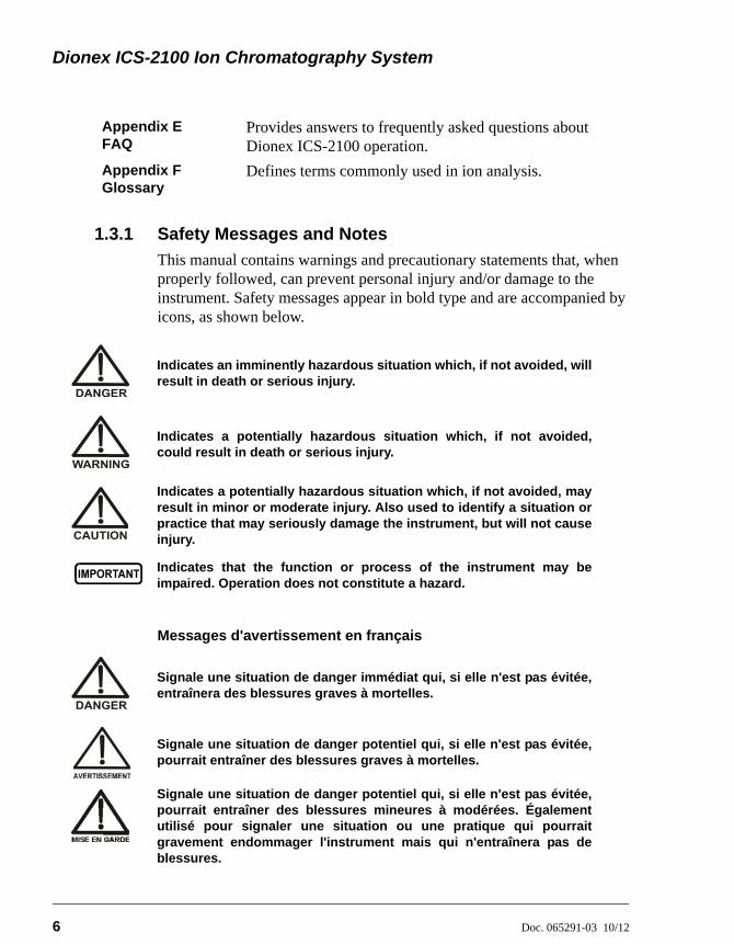
1.3.1 Safety Messages and Notes
This manual contains warnings and precautionary statements that, when properly followed, can prevent personal injury and/or damage to the instrument. Safety messages appear in bold type and are accompanied by icons, as shown below.
Messages d'avertissement en français
Appendix EFAQ
Provides answers to frequently asked questions about Dionex ICS-2100 operation.
Appendix FGlossary
Defines terms commonly used in ion analysis.
Indicates an imminently hazardous situation which, if not avoided, willresult in death or serious injury.
Indicates a potentially hazardous situation which, if not avoided,could result in death or serious injury.
Indicates a potentially hazardous situation which, if not avoided, mayresult in minor or moderate injury. Also used to identify a situation orpractice that may seriously damage the instrument, but will not causeinjury.
Indicates that the function or process of the instrument may beimpaired. Operation does not constitute a hazard.
Signale une situation de danger immédiat qui, si elle n'est pas évitée,entraînera des blessures graves à mortelles.
Signale une situation de danger potentiel qui, si elle n'est pas évitée,pourrait entraîner des blessures graves à mortelles.
Signale une situation de danger potentiel qui, si elle n'est pas évitée,pourrait entraîner des blessures mineures à modérées. Égalementutilisé pour signaler une situation ou une pratique qui pourraitgravement endommager l'instrument mais qui n'entraînera pas deblessures.
1 • Introduction
Doc. 065291-03 10/12 7
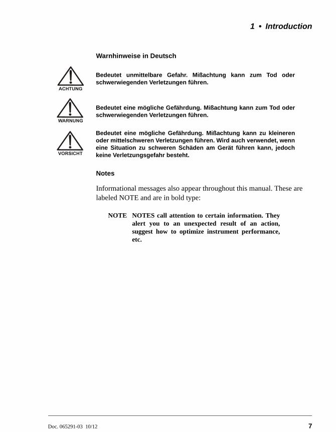
Warnhinweise in Deutsch
Notes
Informational messages also appear throughout this manual. These are labeled NOTE and are in bold type:
NOTE NOTES call attention to certain information. Theyalert you to an unexpected result of an action,suggest how to optimize instrument performance,etc.
Bedeutet unmittelbare Gefahr. Mißachtung kann zum Tod oderschwerwiegenden Verletzungen führen.
Bedeutet eine mögliche Gefährdung. Mißachtung kann zum Tod oderschwerwiegenden Verletzungen führen.
Bedeutet eine mögliche Gefährdung. Mißachtung kann zu kleinerenoder mittelschweren Verletzungen führen. Wird auch verwendet, wenneine Situation zu schweren Schäden am Gerät führen kann, jedochkeine Verletzungsgefahr besteht.
Dionex ICS-2100 Ion Chromatography System
8 Doc. 065291-03 10/12
1.4 Safety and Regulatory Information
The Dionex ICS-2100 was manufactured by Thermo Fisher Scientific at the following location: 527 Lakeside Drive, Sunnyvale, CA 94088-3603 U.S.A. The Dionex ICS-2100 is designed for IC (ion chromatography) applications and should not be used for any other purpose. Operation of a Dionex ICS-2100 in a manner not specified by Thermo Fisher Scientific may result in personal injury. If there is a question regarding appropriate usage, contact Technical Support for Dionex products. In the U.S. and Canada, call 1-800-346-6390. Outside the U.S. and Canada, call the nearest Thermo Fisher Scientific office.
1.4.1 Safety Labels
The TUV T-Mark and cTUVus Mark safety labels and the CE Mark label on the system indicate that it is in compliance with the following standards:
EMC Susceptibility and Emissions
• EN 61326-1:2006
Safety
• CAN/CSA-C22.2 61010-1:2004
• UL 61010-1:2004
• EN 61010-1:2001
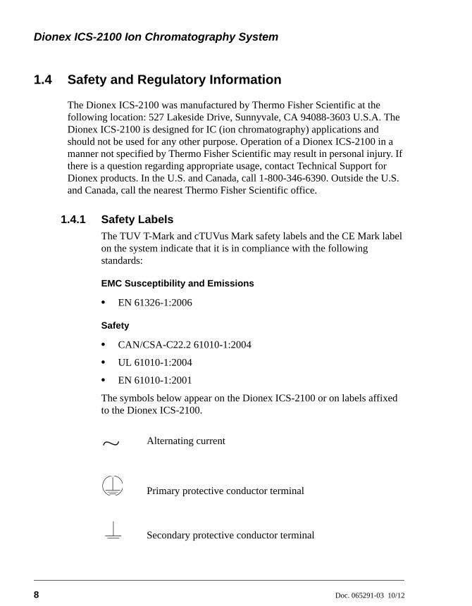
The symbols below appear on the Dionex ICS-2100 or on labels affixed to the Dionex ICS-2100.
Alternating current
Primary protective conductor terminal
Secondary protective conductor terminal

1 • Introduction
Doc. 065291-03 10/12 9
Power supply is on
Power supply is off
Hot surface
Indicates a potential hazard. Refer to the operator’s manual for an explanation of the hazard and how to proceed.

Dionex ICS-2100 Ion Chromatography System
10 Doc. 065291-03 10/12
Doc. 065291-03 10/12 11
2 • Features
This chapter describes key Dionex ICS-2100 features and introduces the Chromeleon user interface.
2.1 Operating Features
2.1.1 Front Panel
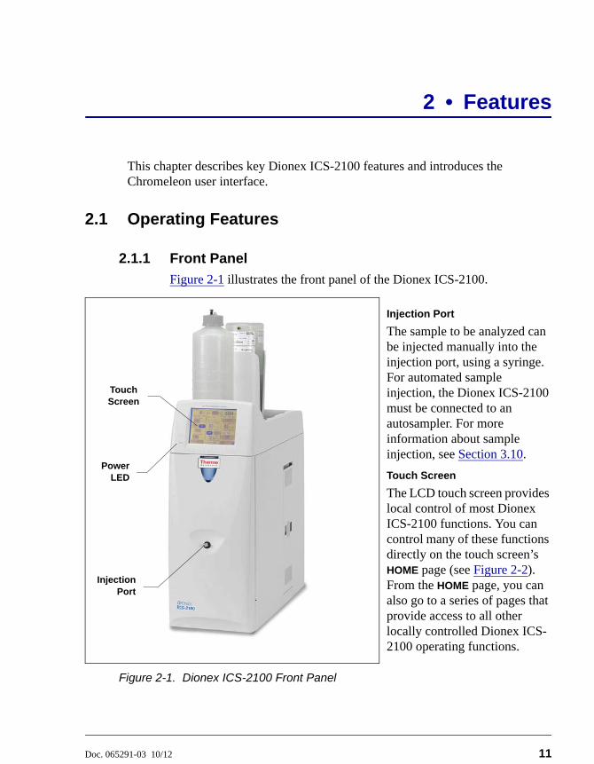
Figure 2-1 illustrates the front panel of the Dionex ICS-2100.
Injection Port
The sample to be analyzed can be injected manually into the injection port, using a syringe. For automated sample injection, the Dionex ICS-2100 must be connected to an autosampler. For more information about sample injection, see Section 3.10.
Touch Screen
The LCD touch screen provides local control of most Dionex ICS-2100 functions. You can control many of these functions directly on the touch screen’s HOME page (see Figure 2-2). From the HOME page, you can also go to a series of pages that provide access to all other locally controlled Dionex ICS-2100 operating functions.
Figure 2-1. Dionex ICS-2100 Front Panel
InjectionPort
PowerLED
Touch Screen
Dionex ICS-2100 Ion Chromatography System
12 Doc. 065291-03 10/12
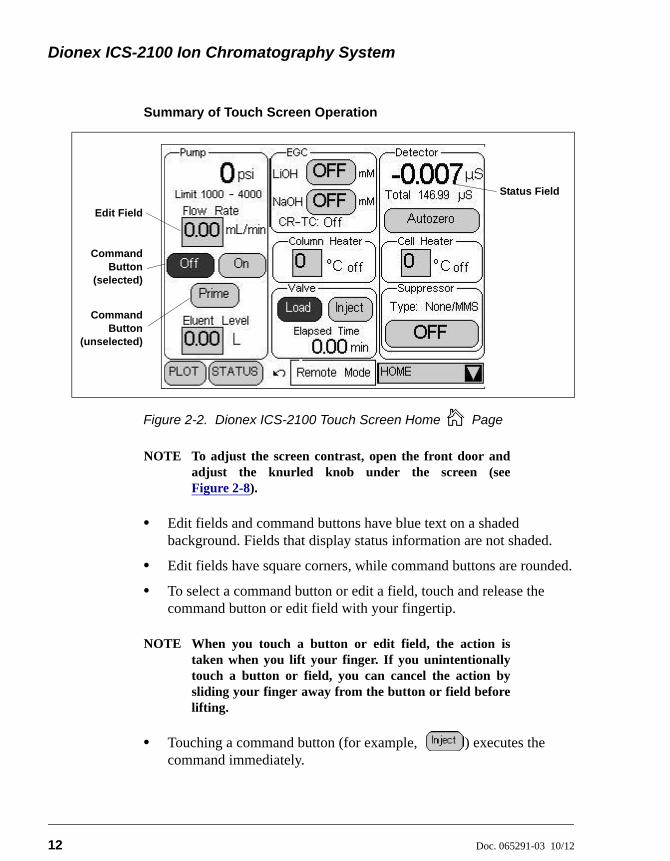
Summary of Touch Screen Operation
NOTE To adjust the screen contrast, open the front door andadjust the knurled knob under the screen (seeFigure 2-8).
• Edit fields and command buttons have blue text on a shaded background. Fields that display status information are not shaded.
• Edit fields have square corners, while command buttons are rounded.
• To select a command button or edit a field, touch and release the command button or edit field with your fingertip.
NOTE When you touch a button or edit field, the action istaken when you lift your finger. If you unintentionallytouch a button or field, you can cancel the action bysliding your finger away from the button or field beforelifting.
• Touching a command button (for example, ) executes the command immediately.
Figure 2-2. Dionex ICS-2100 Touch Screen Home Page
Edit Field
CommandButton
(selected)
CommandButton
(unselected)
Status Field
2 • Features
Doc. 065291-03 10/12 13
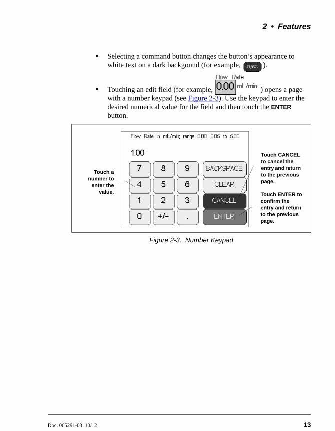
• Selecting a command button changes the button’s appearance to white text on a dark backgound (for example, ).
• Touching an edit field (for example, ) opens a page with a number keypad (see Figure 2-3). Use the keypad to enter the desired numerical value for the field and then touch the ENTER button.
Figure 2-3. Number Keypad
Touch anumber to
enter thevalue. Touch ENTER to
confirm the entry and return to the previous page.
Touch CANCEL to cancel the entry and return to the previous page.
Dionex ICS-2100 Ion Chromatography System
14 Doc. 065291-03 10/12
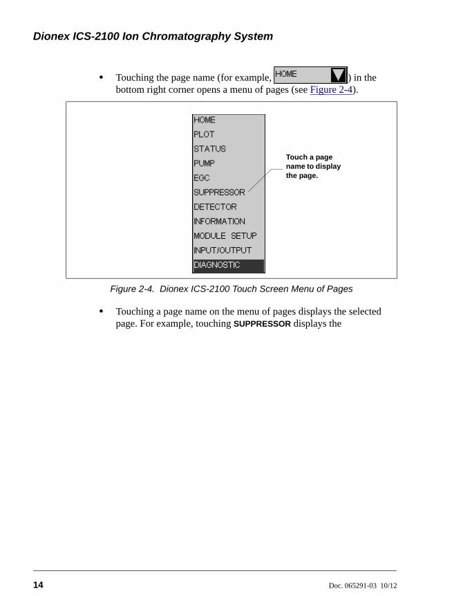
• Touching the page name (for example, ) in the bottom right corner opens a menu of pages (see Figure 2-4).
• Touching a page name on the menu of pages displays the selected page. For example, touching SUPPRESSOR displays the
Figure 2-4. Dionex ICS-2100 Touch Screen Menu of Pages
Touch a page name to display the page.
2 • Features
Doc. 065291-03 10/12 15
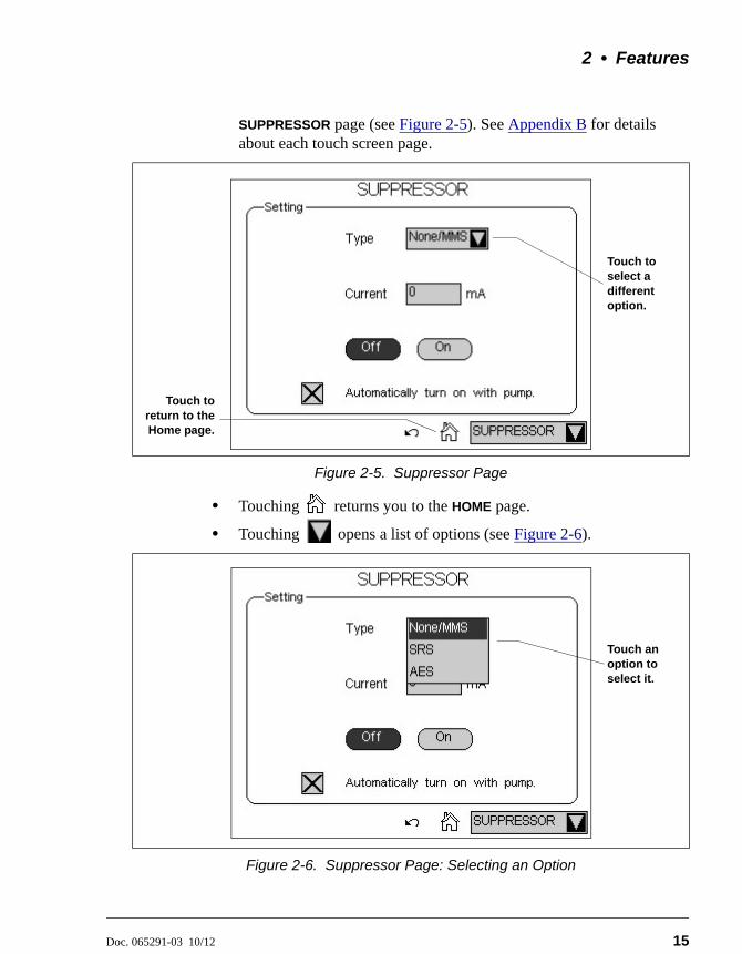
SUPPRESSOR page (see Figure 2-5). See Appendix B for details about each touch screen page.
• Touching returns you to the HOME page.
• Touching opens a list of options (see Figure 2-6).
Figure 2-5. Suppressor Page
Figure 2-6. Suppressor Page: Selecting an Option
Touch toreturn to theHome page.
Touch to select a different option.
Touch an option to select it.
Dionex ICS-2100 Ion Chromatography System
16 Doc. 065291-03 10/12
2.1.2 Top Cover
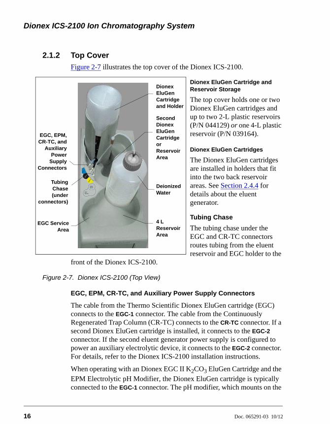
Figure 2-7 illustrates the top cover of the Dionex ICS-2100.
Dionex EluGen Cartridge and Reservoir Storage
The top cover holds one or two Dionex EluGen cartridges and up to two 2-L plastic reservoirs (P/N 044129) or one 4-L plastic reservoir (P/N 039164).
Dionex EluGen Cartridges
The Dionex EluGen cartridges are installed in holders that fit into the two back reservoir areas. See Section 2.4.4 for details about the eluent generator.
Tubing Chase
The tubing chase under the EGC and CR-TC connectors routes tubing from the eluent reservoir and EGC holder to the
front of the Dionex ICS-2100.
Figure 2-7. Dionex ICS-2100 (Top View)
EGC, EPM, CR-TC, and Auxiliary Power Supply Connectors
The cable from the Thermo Scientific Dionex EluGen cartridge (EGC) connects to the EGC-1 connector. The cable from the Continuously Regenerated Trap Column (CR-TC) connects to the CR-TC connector. If a second Dionex EluGen cartridge is installed, it connects to the EGC-2 connector. If the second eluent generator power supply is configured to power an auxiliary electrolytic device, it connects to the EGC-2 connector. For details, refer to the Dionex ICS-2100 installation instructions.
When operating with an Dionex EGC II K2CO3 EluGen Cartridge and the EPM Electrolytic pH Modifier, the Dionex EluGen cartridge is typically connected to the EGC-1 connector. The pH modifier, which mounts on the
Deionized Water
Dionex EluGen Cartridge and Holder
EGC, EPM,CR-TC, and
AuxiliaryPower
SupplyConnectors
TubingChase(under
connectors)
EGC ServiceArea
4 L Reservoir Area
Second Dionex EluGen Cartridge or Reservoir Area
2 • Features
Doc. 065291-03 10/12 17
side of the Dionex EluGen cartridge holder, is connected to the EGC-2 connector. However, the connections can be reversed, if desired.
EGC Service Area
The EGC service area holds the cartridge during installation and replacement. For details, refer to the Dionex ICS-2100 installation instructions.
Dionex ICS-2100 Ion Chromatography System
18 Doc. 065291-03 10/12
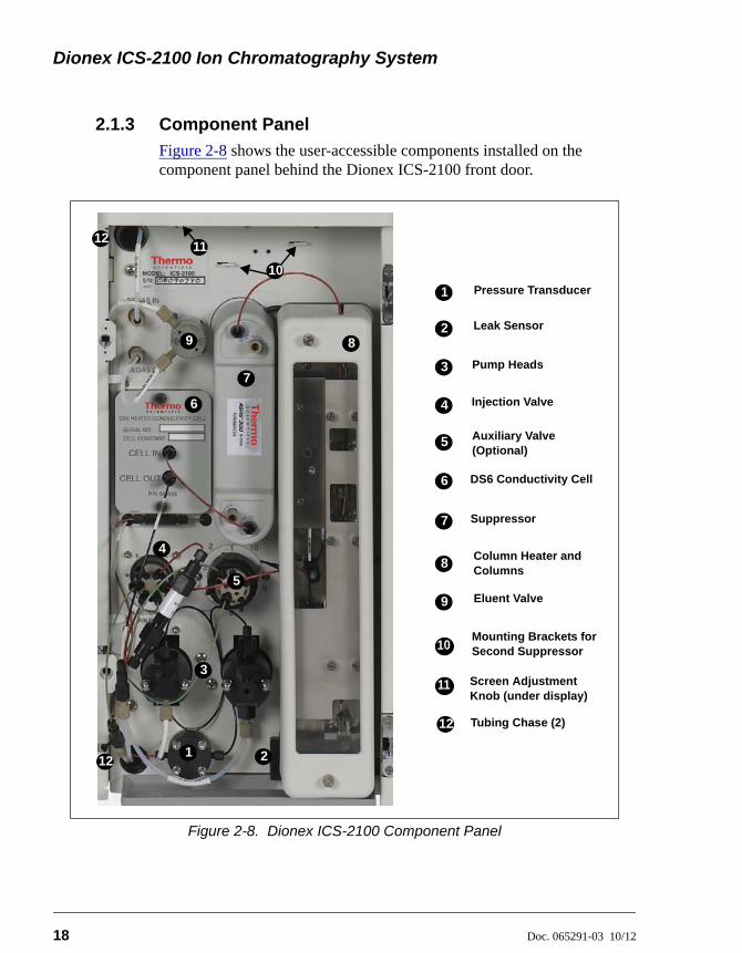
2.1.3 Component Panel
Figure 2-8 shows the user-accessible components installed on the component panel behind the Dionex ICS-2100 front door.
Figure 2-8. Dionex ICS-2100 Component Panel
1 2
3
5
6
7
8
Column Heater and Columns
Auxiliary Valve (Optional)
Pump Heads
Injection Valve
DS6 Conductivity Cell
1
Leak Sensor
Mounting Brackets for Second Suppressor
2
4
5
6
8
9
10
Eluent Valve
Suppressor7
Tubing Chase (2)
11
Pressure Transducer
4
12
12
Screen Adjustment Knob (under display)
11
3
1 2
3
5
6
7
89
12
10
2 • Features
Doc. 065291-03 10/12 19
Pressure Transducer
The pressure transducer measures the system backpressure.
Leak Sensor
The leak sensor is installed in the drip tray at the bottom of the component panel. If liquid accumulates in the tray, an error message is logged in the Chromeleon Audit Trail and displayed on the LCD touch screen.
Pump Heads
The Dionex ICS-2100 includes a dual-piston serial pump. The flow rate can be set to 0.00 mL/min or to between 0.05 and 5.00 mL/min. However, for optimum performance, set the flow rate to between 0.40 and 2.00 mL/min. Setting the flow rate to 0.00 mL/min turns off the pump. See Section 2.4.3 for details about the pump.
Injection Valve
The injection valve is a six-port, electrically-activated Rheodyne valve. A 25-L sample loop (P/N 042857) is installed on the valve at the factory. See Section 2.4.6 for details about valve operation.
Auxiliary Valve (Optional)
The auxiliary valve is a two-position, electrically-activated Rheodyne valve (6-Port Valve Kit, P/N 069472; 10-Port Valve Kit, P/N 069473). See Section 2.4.6 for details about valve operation.
DS6 Heated Conductivity Cell
The flow-through conductivity cell measures the electrical conductance of analyte ions as they pass through the cell. A heat exchanger inside the cell regulates the temperature, which can be set to between 30 and 55 °C. For optimum performance, set the temperature to at least 7 °C above the ambient temperature and 5 °C above the column oven temperature. See Section 2.4.10 for details about the cell.
Dionex ICS-2100 Ion Chromatography System
20 Doc. 065291-03 10/12
Suppressor
The suppressor reduces the eluent conductivity and enhances the conductivity of the sample ions, thereby increasing detection sensitivity.
Either a Dionex AES™ Atlas Electrolytic Suppressor, Dionex SRS™ Self-
Regenerating Suppressor, or Dionex MMS™ MicroMembrane™ Suppressor can be used with the Dionex ICS-2100. See Section 2.4.9 for details about the suppressor.
Separator and Guard Columns
Both the separator and guard columns are packed with resin and perform the separation of the sample ions. The main function of the guard column is to trap contaminants and remove particulates that might damage the separator column.
Column Heater
The column heater controls the temperature of the separator and guard columns. The temperature can be set to between 30 and 60 °C; however, it must be set to at least 5 °C above the ambient temperature. See Section 2.4.8 for details about the column heater.
Eluent Valve
The eluent valve controls the flow from the eluent reservoir. The eluent valve opens automatically when the pump is started and closes when the pump is turned off.
Screen Adjustment Knob
Use this knob to change the LCD touch screen contrast.
Tubing Chases
The upper tubing chase routes tubing from the top cover to the component panel. The lower tubing chase routes tubing from the component panel, through the interior of the Dionex ICS-2100, to the rear panel.
2 • Features
Doc. 065291-03 10/12 21
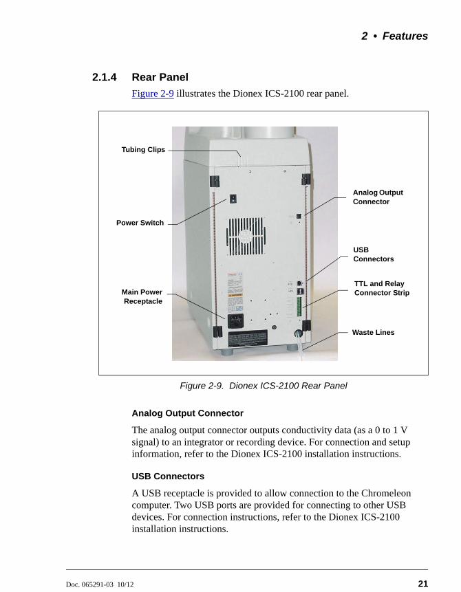
2.1.4 Rear Panel
Figure 2-9 illustrates the Dionex ICS-2100 rear panel.
Analog Output Connector
The analog output connector outputs conductivity data (as a 0 to 1 V signal) to an integrator or recording device. For connection and setup information, refer to the Dionex ICS-2100 installation instructions.
USB Connectors
A USB receptacle is provided to allow connection to the Chromeleon computer. Two USB ports are provided for connecting to other USB devices. For connection instructions, refer to the Dionex ICS-2100 installation instructions.
Figure 2-9. Dionex ICS-2100 Rear Panel
Power Switch
Analog Output Connector
USB Connectors
TTL and Relay Connector Strip
Waste Lines
Main PowerReceptacle
Tubing Clips
12
Dionex ICS-2100 Ion Chromatography System
22 Doc. 065291-03 10/12
TTL and Relay Connector
The TTL and Relay connector strip provides two TTL outputs, two relay outputs, and four TTL inputs. The outputs can be used to control functions in other TTL- or relay-controllable devices. The inputs can be used to switch the injection valve position, turn on the pump, perform an autozero command, and send an event mark to the analog output. See Section C.1 for connection instructions.
Tubing Chases
The lower chase routes tubing from the rear panel to the component panel.
Tubing Clips
The tubing clips hold tubing routed from the top cover in place.
Power Switch
The power switch provides on/off control of power to the Dionex ICS-2100.
Main Power Receptacle
The power supply cord plugs into the AC power receptacle.
The power supply cord is used as the main disconnect device. Makesure the socket-outlet is located near the Dionex ICS-2100 and iseasily accessible.
Le cordon d'alimentation principal est utilisé comme dispositifprincipal de débranchement. Veillez à ce que la prise de base soitsituée/installée près du module et facilement accessible.
Das Netzkabel ist das wichtigste Mittel zur Stromunterbrechung.Stellen Sie sicher, daß sich die Steckdose nahe am Gerät befindet undleicht zugänglich ist.
2 • Features
Doc. 065291-03 10/12 23
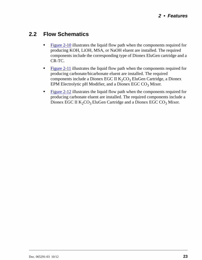
2.2 Flow Schematics
• Figure 2-10 illustrates the liquid flow path when the components required for producing KOH, LiOH, MSA, or NaOH eluent are installed. The required components include the corresponding type of Dionex EluGen cartridge and a CR-TC.
• Figure 2-11 illustrates the liquid flow path when the components required for producing carbonate/bicarbonate eluent are installed. The required components include a Dionex EGC II K2CO3 EluGen Cartridge, a Dionex EPM Electrolytic pH Modifier, and a Dionex EGC CO3 Mixer.
• Figure 2-12 illustrates the liquid flow path when the components required for producing carbonate eluent are installed. The required components include a Dionex EGC II K2CO3 EluGen Cartridge and a Dionex EGC CO3 Mixer.
Dionex ICS-2100 Ion Chromatography System
24 Doc. 065291-03 10/12
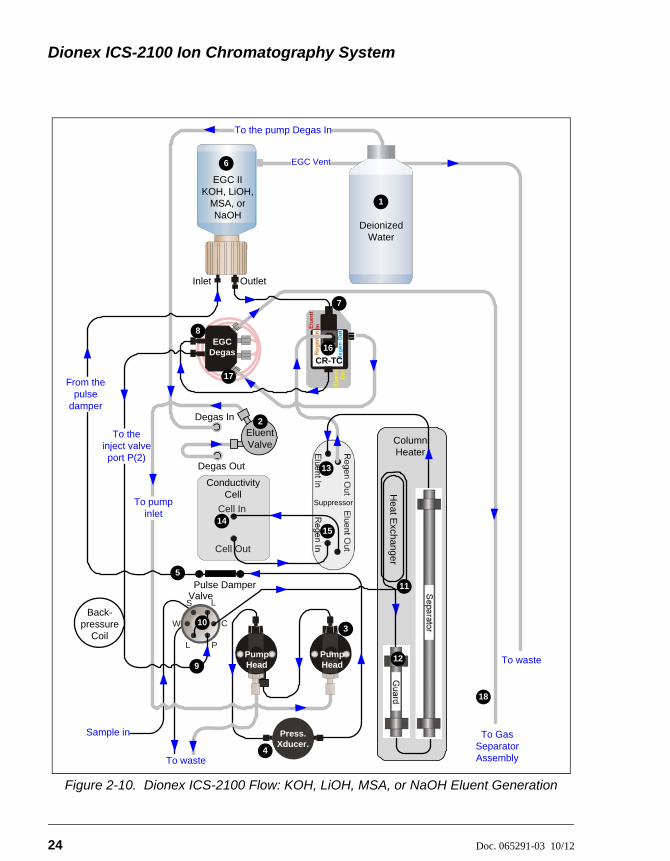
Figure 2-10. Dionex ICS-2100 Flow: KOH, LiOH, MSA, or NaOH Eluent Generation
Sample in
To the pump Degas In
Cell In
Cell Out
Column Heater
Suppressor
Heat E
xchang
er
To pump inlet
Degas Out
Pulse Damper
EGC Degas
From the pulse
damperDegas In
To waste
Eluent Valve
Pump Head
Pump Head
CR-TC
2
3
5
7
8
12
13
1415
16
17
6
EGC IIKOH, LiOH,
MSA, or NaOH
Inlet Outlet
To Gas Separator Assembly
18
Conductivity Cell
L
L
S
W
P
C10
To the inject valve port P(2)
9
11
Back-pressure
Coil
Valve
EGC Vent
To waste
Deionized Water
1
4
Press.Xducer.
2 • Features
Doc. 065291-03 10/12 25
Flow Description for KOH, LiOH, MSA, or NaOH Eluent Generation
Refer to Figure 2-10 for the flow path number locations.
• Deionized water from the reservoir flows first through the pump degas assembly and then through the eluent valve to the pump . The water is then pushed through the pressure transducer , which measures the system pressure. From there, the water flows through a pulse damper , which smooths minor pressure variations from the pump to minimize baseline noise.
• Water then flows into the Dionex EluGen cartridge (EGC) , which generates the programmed concentration of eluent. Eluent exits the cartridge and flows through the CR-TC (which traps ionic contaminants), through the EGC degas tubing assembly , and on to the injection valve .
• After sample is loaded into the sample loop and the injection valve is toggled to the Inject position, eluent passes through the sample loop.
• The eluent/sample mixture is pumped through the heat exchanger , which heats the mixture to the column heater temperature. The mixture then goes to the guard and separator columns and through the suppressor .
• From the suppressor, the mixture flows through the cell , where the analytes are detected. A digital signal is sent to Chromeleon software. Analog output can be collected simultaneously.
• The mixture flows out of the cell and is recycled back into the suppressor , where it is the water source for the regenerant chamber.
• Regenerant waste from the suppressor is directed back to the CR-TC , and then to the EGC degas tubing , where any released hydrogen or oxygen gas is removed before it is sent to the gas separator assembly and then to waste .
11
12 13
14
15
16
17
18
Dionex ICS-2100 Ion Chromatography System
26 Doc. 065291-03 10/12
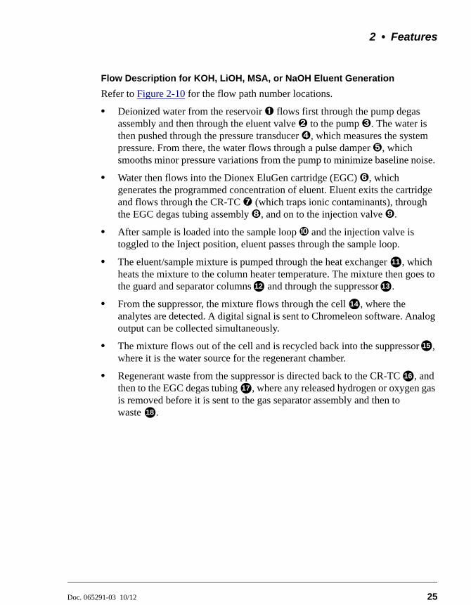
Figure 2-11. Dionex ICS-2100 Flow: Carbonate/Bicarbonate Eluent Generation
L
L
S
W
P
C
7EPM
Eluent In
Eluent Out
Regen Out
Regen In17
To the pump Degas In
Cell In
Cell Out
Column Heater
Suppressor
Hea
t Excha
nge
r
To pump inlet
Degas Out
Pulse DamperValve
11
EGC Degas
Degas In
To waste
Se
parator3
5
8
6
EGC II K2CO3
Inlet Outlet
To Gas Separator Assembly
Conductivity Cell
Sample in
Back-pressure
Coil
10
12
13
14
1516
18
19
EGC Vent
To waste
Deionized Water
1
9
Pump Head
Pump Head
EG
C C
O3 M
ixer
Eluent Valve
2
4
Press.Xducer.
2 • Features
Doc. 065291-03 10/12 27
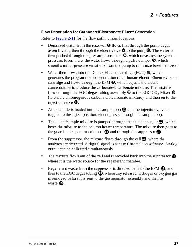
Flow Description for Carbonate/Bicarbonate Eluent Generation
Refer to Figure 2-11 for the flow path number locations.
• Deionized water from the reservoir flows first through the pump degas assembly and then through the eluent valve to the pump. The water is then pushed through the pressure transducer , which measures the system pressure. From there, the water flows through a pulse damper , which smooths minor pressure variations from the pump to minimize baseline noise.
• Water then flows into the Dionex EluGen cartridge (EGC) , which generates the programmed concentration of carbonate eluent. Eluent exits the cartridge and flows through the EPM, which adjusts the eluent concentration to produce the carbonate/bicarbonate mixture. The mixture flows through the EGC degas tubing assembly to the EGC CO3 Mixer (to ensure a homogenous carbonate/bicarbonate mixture), and then on to the injection valve .
• After sample is loaded into the sample loop and the injection valve is toggled to the Inject position, eluent passes through the sample loop.
• The eluent/sample mixture is pumped through the heat exchanger , which heats the mixture to the column heater temperature. The mixture then goes to the guard and separator columns and through the suppressor .
• From the suppressor, the mixture flows through the cell , where the analytes are detected. A digital signal is sent to Chromeleon software. Analog output can be collected simultaneously.
• The mixture flows out of the cell and is recycled back into the suppressor , where it is the water source for the regenerant chamber.
• Regenerant waste from the suppressor is directed back to the EPM , and then to the EGC degas tubing , where any released hydrogen or oxygen gas is removed before it is sent to the gas separator assembly and then to waste .
11
12
13 14
15
16
17
18
19
Dionex ICS-2100 Ion Chromatography System
28 Doc. 065291-03 10/12
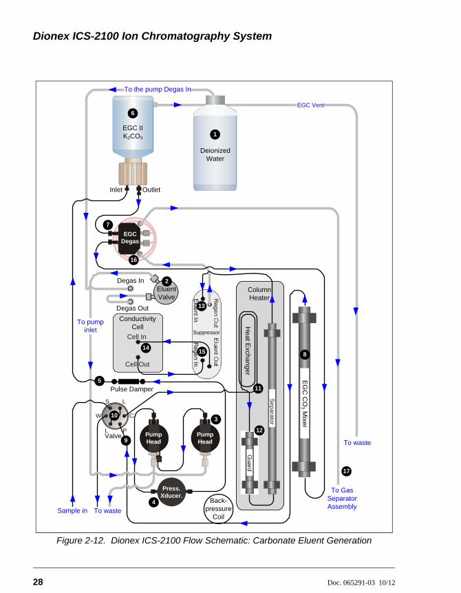
Figure 2-12. Dionex ICS-2100 Flow Schematic: Carbonate Eluent Generation
L
L
S
W
P
C10
7
17
To the pump Degas In
Cell In
Cell Out
Column Heater
Suppressor
He
at E
xcha
nger
Pulse Damper
EGC Degas
To waste
Se
parato
r3
Inlet Outlet
To Gas Separator Assembly
Conductivity Cell
Back-pressure
Coil
Valve
11
12
13
1415
16
EGC Vent
To waste
Deionized Water
1
9
Pump Head
Pump Head
EG
C C
O3 M
ixer
8
4
Press.Xducer.
Degas Out
Degas InEluent Valve
2
To pump inlet
Sample in
5
6
EGC II K2CO3
2 • Features
Doc. 065291-03 10/12 29
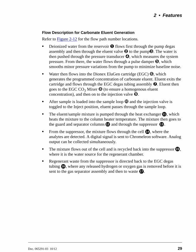
Flow Description for Carbonate Eluent Generation
Refer to Figure 2-12 for the flow path number locations.
• Deionized water from the reservoir flows first through the pump degas assembly and then through the eluent valve to the pump. The water is then pushed through the pressure transducer , which measures the system pressure. From there, the water flows through a pulse damper , which smooths minor pressure variations from the pump to minimize baseline noise.
• Water then flows into the Dionex EluGen cartridge (EGC) , which generates the programmed concentration of carbonate eluent. Eluent exits the cartridge and flows through the EGC degas tubing assembly. Eluent then goes to the EGC CO3 Mixer (to ensure a homogenous eluent concentration), and then on to the injection valve.
• After sample is loaded into the sample loop and the injection valve is toggled to the Inject position, eluent passes through the sample loop.
• The eluent/sample mixture is pumped through the heat exchanger , which heats the mixture to the column heater temperature. The mixture then goes to the guard and separator columns and through the suppressor .
• From the suppressor, the mixture flows through the cell , where the analytes are detected. A digital signal is sent to Chromeleon software. Analog output can be collected simultaneously.
• The mixture flows out of the cell and is recycled back into the suppressor , where it is the water source for the regenerant chamber.
• Regenerant waste from the suppressor is directed back to the EGC degas tubing , where any released hydrogen or oxygen gas is removed before it is sent to the gas separator assembly and then to waste .
11
12 13
14
15
16
17
Dionex ICS-2100 Ion Chromatography System
30 Doc. 065291-03 10/12
2.3 Chromeleon and Chromeleon Xpress
The Dionex ICS-2100 is controlled by a PC configured with Chromeleon Chromatography Management System or Chromeleon Xpress. Chromeleon Chromatography Management System provides complete instrument control, data acquisition, and data management. Chromeleon Xpress provides real-time control and monitoring of instruments, but does not include data management capabilities.
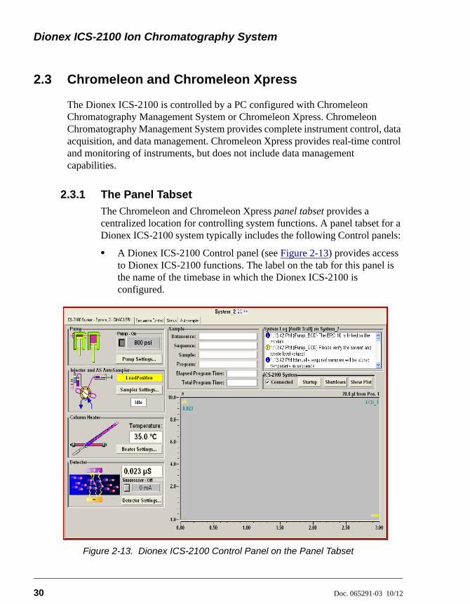
2.3.1 The Panel Tabset
The Chromeleon and Chromeleon Xpress panel tabset provides a centralized location for controlling system functions. A panel tabset for a Dionex ICS-2100 system typically includes the following Control panels:
• A Dionex ICS-2100 Control panel (see Figure 2-13) provides access to Dionex ICS-2100 functions. The label on the tab for this panel is the name of the timebase in which the Dionex ICS-2100 is configured.
Figure 2-13. Dionex ICS-2100 Control Panel on the Panel Tabset
2 • Features
Doc. 065291-03 10/12 31
• A Sequence Control panel lets you define and run sequences (groups of sample injections to be analyzed in the order in which they are listed).
• A Status panel shows the overall system status.
• An Autosampler panel (included if the Dionex ICS-2100 is connected to a Dionex AS, Dionex AS-AP, Dionex AS-DV, or Dionex AS-HV Autosampler) provides access to autosampler functions.
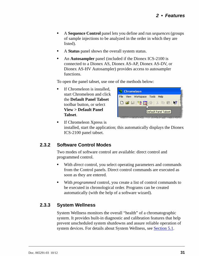
To open the panel tabset, use one of the methods below:
• If Chromeleon is installed, start Chromeleon and click the Default Panel Tabset toolbar button, or select View > Default Panel Tabset.
• If Chromeleon Xpress is installed, start the application; this automatically displays the Dionex ICS-2100 panel tabset.
2.3.2 Software Control Modes
Two modes of software control are available: direct control and programmed control.
• With direct control, you select operating parameters and commands from the Control panels. Direct control commands are executed as soon as they are entered.
• With programmed control, you create a list of control commands to be executed in chronological order. Programs can be created automatically (with the help of a software wizard).
2.3.3 System Wellness
System Wellness monitors the overall “health” of a chromatographic system. It provides built-in diagnostic and calibration features that help prevent unscheduled system shutdowns and assure reliable operation of system devices. For details about System Wellness, see Section 5.1.
Dionex ICS-2100 Ion Chromatography System
32 Doc. 065291-03 10/12
2.4 System Component Details
This section provides details about Dionex ICS-2100 system components, including the vacuum degas assembly, pump, eluent generator, injection valve, column heater, suppressor, auxiliary power supply, and conductivity cell.
2.4.1 Vacuum Degas Assembly (Optional)
The vacuum degas assembly provides online eluent degassing at the time and duration specified by the user. The assembly, which must be installed in the Dionex ICS-2100 at the factory, consists of:
• A single-channel degas chamber (with degas membranes) with internal capacity of 17 mL
• A dual-stage diaphragm vacuum pump
• A solenoid valve
• An on-board vacuum sensor
• The electronics required to operate the vacuum pump
• Tubing, fittings, and other accessories
By default, the Dionex ICS-2100 monitors the degas pressure reading and turns the degas pump on and off as needed. Different degas operating modes can be selected from the touch screen PUMP page (see Section B.7) or from Chromeleon.
To select the degas operating options, open the Chromeleon Server Configuration program, right-click the Dionex ICS-2100 device in the timebase, and select Properties.
2 • Features
Doc. 065291-03 10/12 33
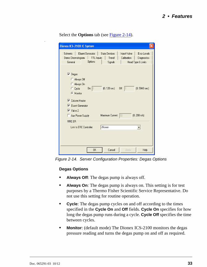
Select the Options tab (see Figure 2-14)..
Figure 2-14. Server Configuration Properties: Degas Options
Degas Options
• Always Off: The degas pump is always off.
• Always On: The degas pump is always on. This setting is for test purposes by a Thermo Fisher Scientific Service Representative. Do not use this setting for routine operation.
• Cycle: The degas pump cycles on and off according to the times specified in the Cycle On and Off fields. Cycle On specifies for how long the degas pump runs during a cycle. Cycle Off specifies the time between cycles.
• Monitor: (default mode) The Dionex ICS-2100 monitors the degas pressure reading and turns the degas pump on and off as required.
Dionex ICS-2100 Ion Chromatography System
34 Doc. 065291-03 10/12
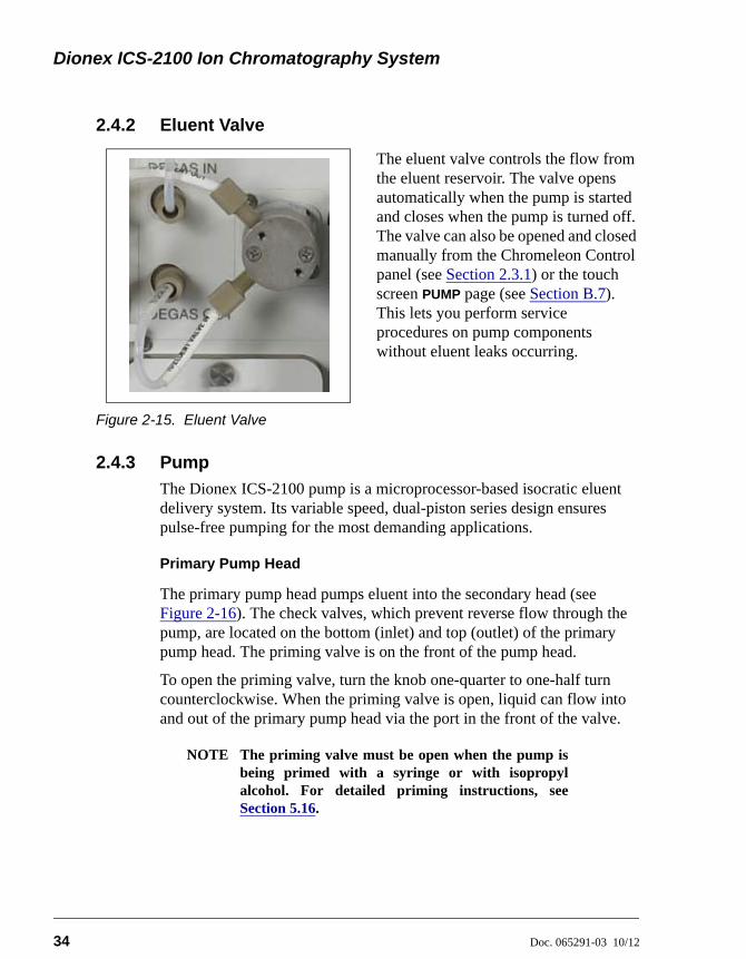
2.4.2 Eluent Valve
2.4.3 Pump
The Dionex ICS-2100 pump is a microprocessor-based isocratic eluent delivery system. Its variable speed, dual-piston series design ensures pulse-free pumping for the most demanding applications.
Primary Pump Head
The primary pump head pumps eluent into the secondary head (see Figure 2-16). The check valves, which prevent reverse flow through the pump, are located on the bottom (inlet) and top (outlet) of the primary pump head. The priming valve is on the front of the pump head.
To open the priming valve, turn the knob one-quarter to one-half turn counterclockwise. When the priming valve is open, liquid can flow into and out of the primary pump head via the port in the front of the valve.
NOTE The priming valve must be open when the pump isbeing primed with a syringe or with isopropylalcohol. For detailed priming instructions, seeSection 5.16.
The eluent valve controls the flow from the eluent reservoir. The valve opens automatically when the pump is started and closes when the pump is turned off. The valve can also be opened and closed manually from the Chromeleon Control panel (see Section 2.3.1) or the touch screen PUMP page (see Section B.7). This lets you perform service procedures on pump components without eluent leaks occurring.
Figure 2-15. Eluent Valve
2 • Features
Doc. 065291-03 10/12 35
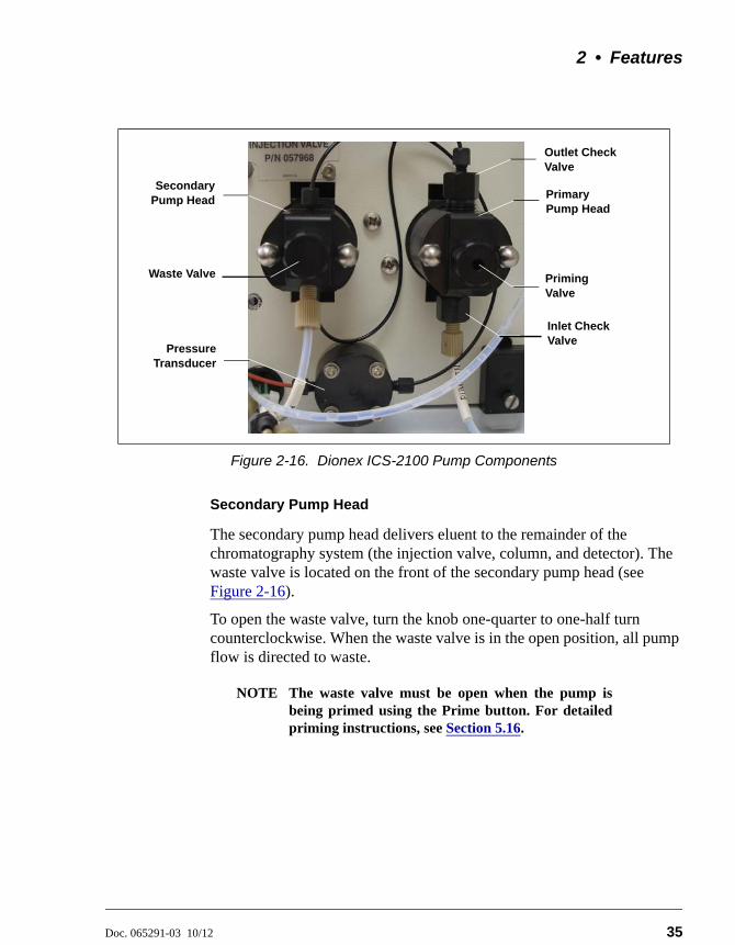
Secondary Pump Head
The secondary pump head delivers eluent to the remainder of the chromatography system (the injection valve, column, and detector). The waste valve is located on the front of the secondary pump head (see Figure 2-16).
To open the waste valve, turn the knob one-quarter to one-half turn counterclockwise. When the waste valve is in the open position, all pump flow is directed to waste.
NOTE The waste valve must be open when the pump isbeing primed using the Prime button. For detailedpriming instructions, see Section 5.16.
Figure 2-16. Dionex ICS-2100 Pump Components
SecondaryPump Head Primary
Pump Head
Outlet Check Valve
Inlet Check Valve
Priming Valve
Waste Valve
PressureTransducer
Dionex ICS-2100 Ion Chromatography System
36 Doc. 065291-03 10/12
Pressure Transducer
Flow exiting the secondary pump head is directed to the pressure transducer (see Figure 2-16), which measures the system pressure.
Pressure readings indicate that the pumping system is delivering smooth, accurate flow. Pressure readings can be monitored from the Chromeleon Control panel or the touch screen HOME page.
The system pressure should remain consistent (no more than a 3% difference from one pressure reading to the next). High and low pressure limits can be used to stop the pump flow if a limit is exceeded. The pressure limits can be set from Chromeleon (in the Server Configuration or in the control program) or from the touch screen PUMP page (see Section B.7). See Section 4.2 for troubleshooting information if a pressure limit is exceeded.
Pulse Damper
Flow output from the pressure transducer continues to the pulse damper, which smooths minor pressure variations. From there, flow is directed to the injection valve and then to the remainder of the chromatography system.
Piston Seal Wash
The pump includes a piston seal wash assembly that can be set up to continuously rinse the back of the piston seals to remove salt crystals and prolong the life of the seals. To use this feature, an external water source must be connected. For connection instructions, refer to the Dionex ICS-2100 installation instructions.
For continued protection of the pump, replace the piston rinse seals (see Section 5.7) and O-rings in the seal wash assembly every 6 months, or whenever you replace the main piston seals for the Dionex ICS-2100 pump.
2 • Features
Doc. 065291-03 10/12 37
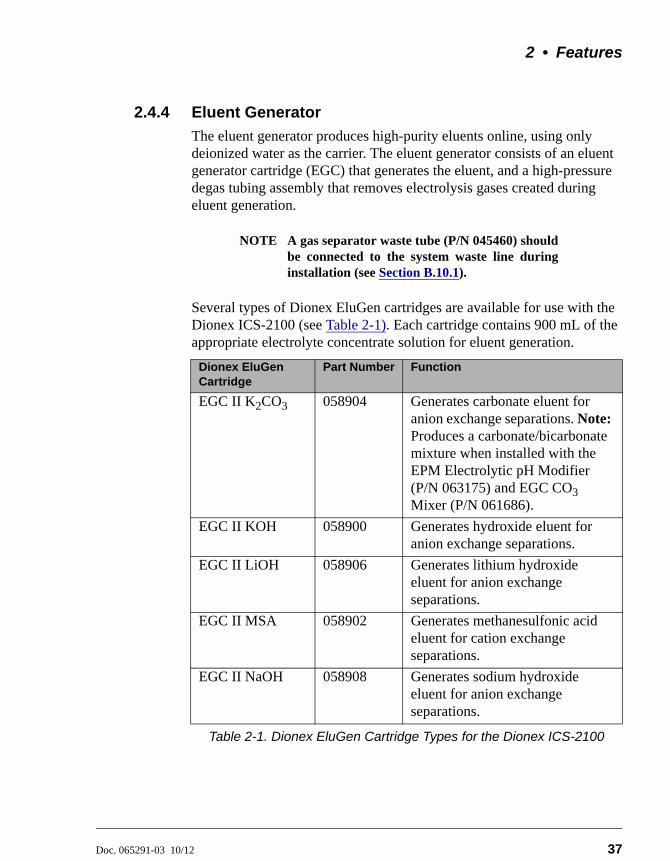
2.4.4 Eluent Generator
The eluent generator produces high-purity eluents online, using only deionized water as the carrier. The eluent generator consists of an eluent generator cartridge (EGC) that generates the eluent, and a high-pressure degas tubing assembly that removes electrolysis gases created during eluent generation.
NOTE A gas separator waste tube (P/N 045460) shouldbe connected to the system waste line duringinstallation (see Section B.10.1).
Several types of Dionex EluGen cartridges are available for use with the Dionex ICS-2100 (see Table 2-1). Each cartridge contains 900 mL of the appropriate electrolyte concentrate solution for eluent generation.
Dionex EluGen Cartridge
Part Number Function
EGC II K2CO3 058904 Generates carbonate eluent for anion exchange separations. Note: Produces a carbonate/bicarbonate mixture when installed with the EPM Electrolytic pH Modifier (P/N 063175) and EGC CO3 Mixer (P/N 061686).
EGC II KOH 058900 Generates hydroxide eluent for anion exchange separations.
EGC II LiOH 058906 Generates lithium hydroxide eluent for anion exchange separations.
EGC II MSA 058902 Generates methanesulfonic acid eluent for cation exchange separations.
EGC II NaOH 058908 Generates sodium hydroxide eluent for anion exchange separations.
Table 2-1. Dionex EluGen Cartridge Types for the Dionex ICS-2100
Dionex ICS-2100 Ion Chromatography System
38 Doc. 065291-03 10/12
For more information, refer to the Dionex EluGen cartridge manual. The manual is included on the Thermo Scientific Reference Library DVD (P/N 053891).
You can select the concentration of eluent to be generated from either the Chromeleon Control panel or from the touch screen HOME page (see Section B.4).
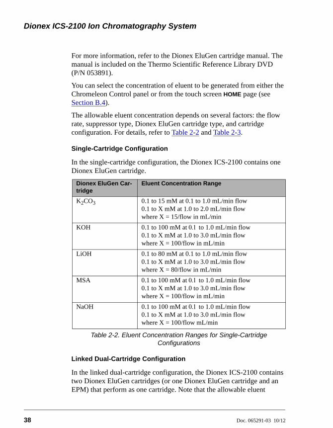
The allowable eluent concentration depends on several factors: the flow rate, suppressor type, Dionex EluGen cartridge type, and cartridge configuration. For details, refer to Table 2-2 and Table 2-3.
Single-Cartridge Configuration
In the single-cartridge configuration, the Dionex ICS-2100 contains one Dionex EluGen cartridge.
Linked Dual-Cartridge Configuration
In the linked dual-cartridge configuration, the Dionex ICS-2100 contains two Dionex EluGen cartridges (or one Dionex EluGen cartridge and an EPM) that perform as one cartridge. Note that the allowable eluent
Dionex EluGen Car-tridge
Eluent Concentration Range
K2CO3 0.1 to 15 mM at 0.1 to 1.0 mL/min flow0.1 to X mM at 1.0 to 2.0 mL/min flowwhere X = 15/flow in mL/min
KOH 0.1 to 100 mM at to 1.0 mL/min flow0.1 to X mM at 1.0 to 3.0 mL/min flowwhere X = 100/flow in mL/min
LiOH 0.1 to 80 mM at 0.1 to 1.0 mL/min flow0.1 to X mM at 1.0 to 3.0 mL/min flowwhere X = 80/flow in mL/min
MSA 0.1 to 100 mM at to 1.0 mL/min flow0.1 to X mM at 1.0 to 3.0 mL/min flowwhere X = 100/flow in mL/min
NaOH 0.1 to 100 mM at to 1.0 mL/min flow0.1 to X mM at 1.0 to 3.0 mL/min flowwhere X = 100/flow mL/min
Table 2-2. Eluent Concentration Ranges for Single-Cartridge Configurations
2 • Features
Doc. 065291-03 10/12 39
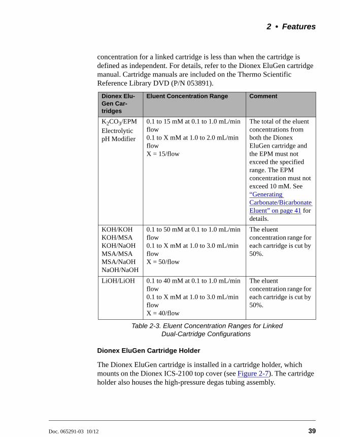
concentration for a linked cartridge is less than when the cartridge is defined as independent. For details, refer to the Dionex EluGen cartridge manual. Cartridge manuals are included on the Thermo Scientific Reference Library DVD (P/N 053891).
Dionex EluGen Cartridge Holder
The Dionex EluGen cartridge is installed in a cartridge holder, which mounts on the Dionex ICS-2100 top cover (see Figure 2-7). The cartridge holder also houses the high-pressure degas tubing assembly.
Dionex Elu-Gen Car-tridges
Eluent Concentration Range Comment
K2CO3/EPM
Electrolytic pH Modifier
0.1 to 15 mM at 0.1 to 1.0 mL/min flow 0.1 to X mM at 1.0 to 2.0 mL/min flowX = 15/flow
The total of the eluent concentrations from both the Dionex EluGen cartridge and the EPM must not exceed the specified range. The EPM concentration must not exceed 10 mM. See “Generating Carbonate/Bicarbonate Eluent” on page 41 for details.
KOH/KOHKOH/MSAKOH/NaOHMSA/MSAMSA/NaOHNaOH/NaOH
0.1 to 50 mM at 0.1 to 1.0 mL/min flow0.1 to X mM at 1.0 to 3.0 mL/min flowX = 50/flow
The eluent concentration range for each cartridge is cut by 50%.
LiOH/LiOH 0.1 to 40 mM at 0.1 to 1.0 mL/min flow0.1 to X mM at 1.0 to 3.0 mL/min flowX = 40/flow
The eluent concentration range for each cartridge is cut by 50%.
Table 2-3. Eluent Concentration Ranges for Linked Dual-Cartridge Configurations
Dionex ICS-2100 Ion Chromatography System
40 Doc. 065291-03 10/12
The Dionex ICS-2100 can control up to two Dionex EluGen cartridges. However, when operating with a Dionex EGC II K2CO3 EluGen Cartridge and the pH Modifier, only one cartridge can be installed, because the pH Modifier must be connected to the other EGC power supply (EGC-1 or EGC-2).
Tubing and fittings for plumbing the cartridge, degas assembly, CR-TC, and EPM are included with the holder. For connection instructions, refer to the Dionex ICS-2100 installation instructions.
Backpressure Coil (Optional)
The Dionex EluGen cartridge requires at least 14 MPa (2000 psi) of system backpressure for removal of electrolysis gas from the eluent produced by the cartridge. A system backpressure of 16 MPa (2300 psi) is ideal.
If necessary, increase the system backpressure by installing a backpressure coil between the injection valve and the Dionex EluGen cartridge OUTLET port. For details, refer to the Dionex ICS-2100 installation instructions.
Continuously Regenerated Trap Column (CR-TC)
The CR-TC is a high pressure electrolytically-regenerated trap column. The CR-TC is designed to remove anionic or cationic contaminants in the eluent or deionized water and to reduce drift during gradient separations. Two versions of the CR-TC can be used with the Dionex ICS-2100:
• CR-ATC (Continuously Regenerated Anion Trap Column, P/N 060477)
• CR-CTC (Continuously Regenerated Cation Trap Column, P/N 060478)
For more information, refer to the CR-TC manual. The manual is included on the Thermo Scientific Reference Library DVD (P/N 053891).
NOTE The IonPac™ ATC-HC Trap Column (P/N 059604)or IonPac CTC-1 Trap Column (P/N 040192) can beused with the Dionex ICS-2100. However, bothIonPac trap columns require off-line chemicalregeneration. Contact Thermo Fisher Scientific formore information.
2 • Features
Doc. 065291-03 10/12 41
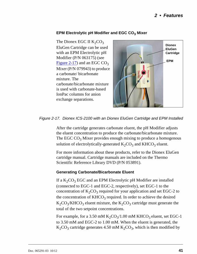
EPM Electrolytic pH Modifier and EGC CO3 Mixer
The Dionex EGC II K2CO3 EluGen Cartridge can be used with an EPM Electrolytic pH Modifier (P/N 063175) (see Figure 2-17) and an EGC CO3 Mixer (P/N 079943) to produce a carbonate/ bicarbonate mixture. The carbonate/bicarbonate mixture is used with carbonate-based IonPac columns for anion exchange separations.
Figure 2-17. Dionex ICS-2100 with an Dionex EluGen Cartridge and EPM Installed
After the cartridge generates carbonate eluent, the pH Modifier adjusts the eluent concentration to produce the carbonate/bicarbonate mixture. The EGC CO3 Mixer provides enough mixing to produce a homogenous solution of electrolytically-generated K2CO3 and KHCO3 eluent.
For more information about these products, refer to the Dionex EluGen cartridge manual. Cartridge manuals are included on the Thermo Scientific Reference Library DVD (P/N 053891).
Generating Carbonate/Bicarbonate Eluent
If a K2CO3 EGC and an EPM Electrolytic pH Modifier are installed (connected to EGC-1 and EGC-2, respectively), set EGC-1 to the concentration of K2CO3 required for your application and set EGC-2 to the concentration of KHCO3 required. In order to achieve the desired K2CO3/KHCO3 eluent mixture, the K2CO3 cartridge must generate the total of the two setpoint concentrations.
For example, for a 3.50 mM K2CO3/1.00 mM KHCO3 eluent, set EGC-1 to 3.50 mM and EGC-2 to 1.00 mM. When the eluent is generated, the K2CO3 cartridge generates 4.50 mM K2CO3, which is then modified by
EPM
Dionex EluGen Cartridge
Dionex ICS-2100 Ion Chromatography System
42 Doc. 065291-03 10/12
the EPM to achieve the desired 3.50 mM K2CO3/1.00 mM KHCO3
mixture.
2.4.5 Auxiliary Power Supply (Optional)
The EGC-2 power supply can be configured as an auxiliary power supply for the operation of an electrolytic device such as a water purifier. The power supply operates in constant current mode and can be configured from 0 to 200 mA, with a maximum voltage of 35 V.
2.4.6 Injection Valve
The injection valve (P/N 057968) is a six-port, electrically-activated valve. A 25-L sample loop (P/N 042857) is installed on the valve at the factory.
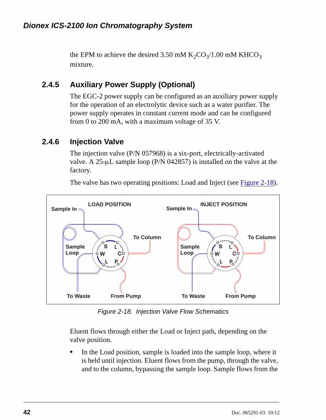
The valve has two operating positions: Load and Inject (see Figure 2-18).
Eluent flows through either the Load or Inject path, depending on the valve position.
• In the Load position, sample is loaded into the sample loop, where it is held until injection. Eluent flows from the pump, through the valve, and to the column, bypassing the sample loop. Sample flows from the
Figure 2-18. Injection Valve Flow Schematics
To Waste
Sample In
To Column
From Pump
SampleLoop
LOAD POSITION
To Waste
Sample In
From Pump
SampleLoop
INJECT POSITION
To Column
2 • Features
Doc. 065291-03 10/12 43
syringe or automated sampler line (if installed), through the valve, and into the sample loop. Excess sample flows out to waste.
• In the Inject position, sample is swept to the column for analysis. Eluent flows from the pump, through the sample loop, and on to the column, carrying the contents of the sample loop with it. Section 3.10 describes how to inject samples.
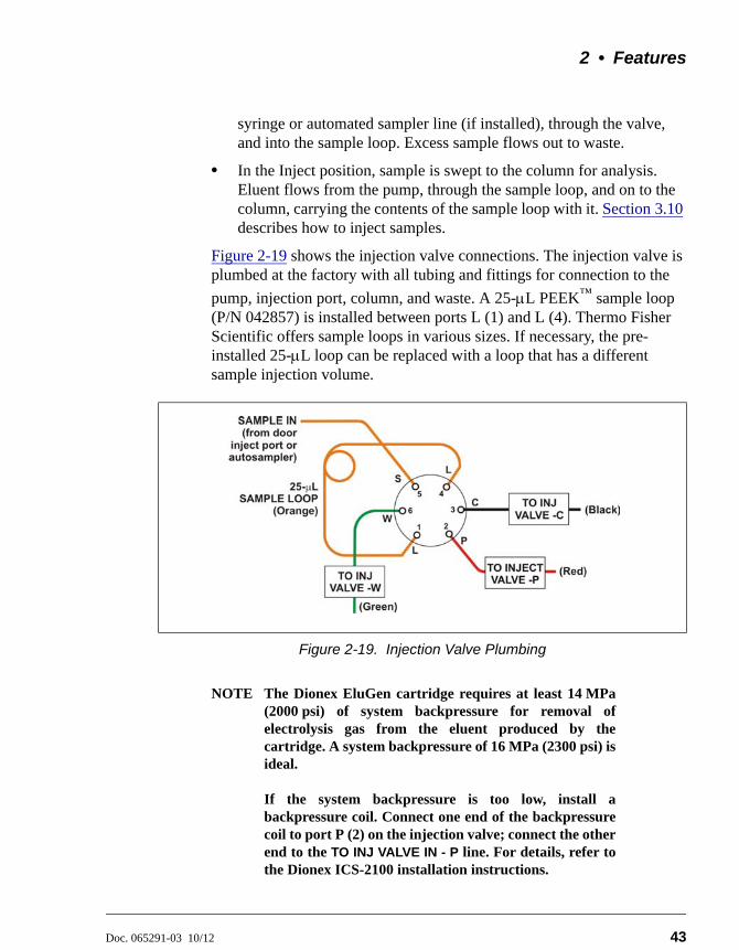
Figure 2-19 shows the injection valve connections. The injection valve is plumbed at the factory with all tubing and fittings for connection to the
pump, injection port, column, and waste. A 25-L PEEK™ sample loop (P/N 042857) is installed between ports L (1) and L (4). Thermo Fisher Scientific offers sample loops in various sizes. If necessary, the pre-installed 25-L loop can be replaced with a loop that has a different sample injection volume.
NOTE The Dionex EluGen cartridge requires at least 14 MPa(2000 psi) of system backpressure for removal ofelectrolysis gas from the eluent produced by thecartridge. A system backpressure of 16 MPa (2300 psi) isideal.
If the system backpressure is too low, install abackpressure coil. Connect one end of the backpressurecoil to port P (2) on the injection valve; connect the otherend to the TO INJ VALVE IN - P line. For details, refer tothe Dionex ICS-2100 installation instructions.
Figure 2-19. Injection Valve Plumbing
Dionex ICS-2100 Ion Chromatography System
44 Doc. 065291-03 10/12
2.4.7 Auxiliary Valve (Optional)
The auxiliary valve is a high-pressure Rheodyne valve. The electrically-activated, 2-position PEEK valve is offered in both 6-port and 10-port models (6-Port Valve Kit, P/N 069472; 10-Port Valve Kit, P/N 069473). The auxiliary valve enables a variety of sample preparation activities, including:
• Online filtration
• Matrix elimination (for example, the removal of high backgrounds of chloride or organic material)
• Concentrator-based techniques
• Conditional injections (large loop/small loop applications where the data system monitors sample concentration and reinjects the sample, using the smaller loop, if the concentration is too high)
• AutoNeutralization™
• Matrix diversion prior to MS (mass spectrometry) detection
For more information, refer to Installing the ICS-1100/ICS-1600/ICS-2100 Auxiliary Valve (Document No. 065288). The manual is provided in the Auxiliary Valve Kit.
2 • Features
Doc. 065291-03 10/12 45
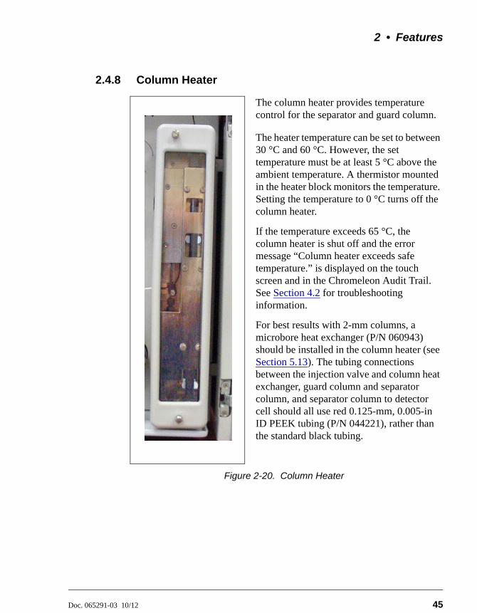
2.4.8 Column Heater
The column heater provides temperature control for the separator and guard column. The heater temperature can be set to between 30 °C and 60 °C. However, the set temperature must be at least 5 °C above the ambient temperature. A thermistor mounted in the heater block monitors the temperature. Setting the temperature to 0 °C turns off the column heater.
If the temperature exceeds 65 °C, the column heater is shut off and the error message “Column heater exceeds safe temperature.” is displayed on the touch screen and in the Chromeleon Audit Trail. See Section 4.2 for troubleshooting information.
For best results with 2-mm columns, a microbore heat exchanger (P/N 060943) should be installed in the column heater (see Section 5.13). The tubing connections between the injection valve and column heat exchanger, guard column and separator column, and separator column to detector cell should all use red 0.125-mm, 0.005-in ID PEEK tubing (P/N 044221), rather than the standard black tubing.
Figure 2-20. Column Heater
Dionex ICS-2100 Ion Chromatography System
46 Doc. 065291-03 10/12
2.4.9 Suppressor
The suppressor reduces the eluent conductivity and enhances the conductivity of the sample ions, thereby increasing detection sensitivity. Either a Dionex Atlas Electrolytic Suppressor, Dionex Self-Regenerating Suppressor, or Dionex MicroMembrane Suppressor can be used with the Dionex ICS-2100.
For details about any of the suppressors or for information about selecting a suppressor for your application, refer to the suppressor manuals. The manuals are on the Thermo Scientific Reference Library DVD (P/N 053891).
2.4.10 DS6 Heated Conductivity Cell
The flow-through conductivity cell measures the electrical conductance of analyte ions as they pass through the cell. Two passivated 316 stainless steel electrodes are permanently sealed into the PEEK cell body. The cell design provides efficient sweep-out, low volume (1 L), and low dispersion. Temperature control and compensation help ensure good peak reproducibility and baseline stability.
Temperature Control
Temperature directly affects the conductivity of a solution. For example, laboratory heating and air conditioning systems can cause a regular slow cycling in the baseline. This, in turn, can affect the reproducibility of an analysis. The higher the conductivity, the more pronounced the effect.
In ion analysis, the effect of temperature variation is minimized by suppressing eluent conductivity. To further reduce the effect of temperature variation, a heater inside the cell regulates the temperature. The cell heater can be set to between 30 °C and 55 °C. The set temperature must be at least 7 °C above the ambient temperature. Setting the cell temperature to 0 °C turns off the cell heater.
Temperature Compensation
Built-in preset temperature compensation of 1.7% per °C helps minimize changes in the baseline or in peak heights when the operating temperature is different from the temperature at which the cell was calibrated.
2 • Features
Doc. 065291-03 10/12 47
DS6 Heated Conductivity Cell Components
The cell front cover provides CELL IN and CELL OUT fittings for connecting the cell to the suppressor (see Figure 2-8). The remaining cell components are mounted behind the component panel. To replace, the cell remove the screws on the cell front cover and pull the entire cell assembly out through the component panel. See Section 5.10 for cell replacement instructions.

Dionex ICS-2100 Ion Chromatography System
48 Doc. 065291-03 10/12
Doc. 065291-03 10/12 49
3 • Operation and Maintenance
This chapter describes routine operating and maintenance procedures for the Dionex ICS-2100.
The Dionex ICS-2100 is designed for IC (ion chromatography) applications and should not be used for any other purpose. Operation of the Dionex ICS-2100 in a manner not specified by Thermo Fisher Scientific may result in personal injury.
3.1 Operation Overview
Figure 3-1 illustrates the basic steps for routine operation of the Dionex ICS-2100.
Figure 3-1. Operation Flow Chart
Power up the system
Set up the reservoir (or RFIC-ER system)
Start Chromeleon
Check all connections
Prime the pump
Set operating conditions
Equilibrate the system
Verify operating status
Process samples
Prepare samples
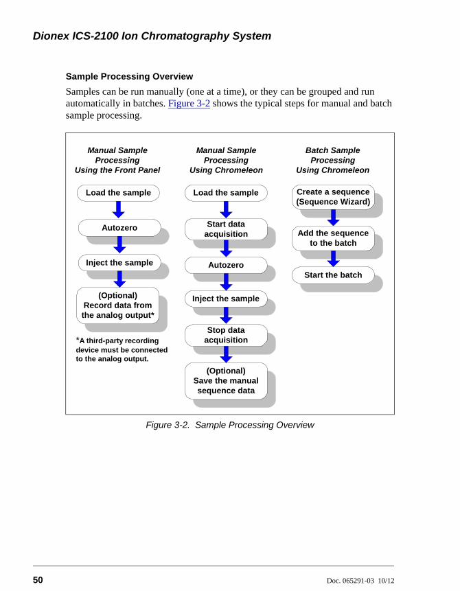
Dionex ICS-2100 Ion Chromatography System
50 Doc. 065291-03 10/12
Sample Processing Overview
Samples can be run manually (one at a time), or they can be grouped and run automatically in batches. Figure 3-2 shows the typical steps for manual and batch sample processing.
Figure 3-2. Sample Processing Overview
Manual SampleProcessing
Using the Front Panel
*A third-party recordingdevice must be connectedto the analog output.
(Optional)Record data fromthe analog output*
Inject the sample
Autozero
Manual SampleProcessing
Using Chromeleon
Inject the sample
Autozero
Stop dataacquisition
(Optional)Save the manualsequence data
Start dataacquisition
Batch SampleProcessing
Using Chromeleon
Create a sequence(Sequence Wizard)
Start the batch
Add the sequenceto the batch
Load the sample Load the sample
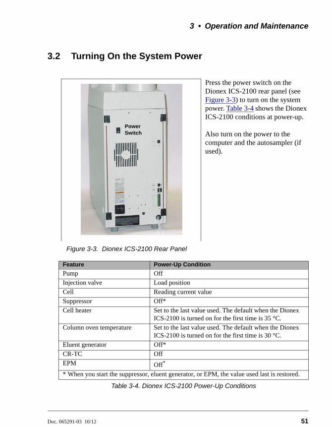
3 • Operation and Maintenance
Doc. 065291-03 10/12 51
3.2 Turning On the System Power
Press the power switch on the Dionex ICS-2100 rear panel (see Figure 3-3) to turn on the system power. Table 3-4 shows the Dionex ICS-2100 conditions at power-up.
Also turn on the power to the computer and the autosampler (if used).
Figure 3-3. Dionex ICS-2100 Rear Panel
Feature Power-Up Condition
Pump Off
Injection valve Load position
Cell Reading current value
Suppressor Off*
Cell heater Set to the last value used. The default when the Dionex ICS-2100 is turned on for the first time is 35 °C.
Column oven temperature Set to the last value used. The default when the Dionex ICS-2100 is turned on for the first time is 30 °C.
Eluent generator Off*
CR-TC Off
EPM Off*
* When you start the suppressor, eluent generator, or EPM, the value used last is restored.
Table 3-4. Dionex ICS-2100 Power-Up Conditions
Power Switch
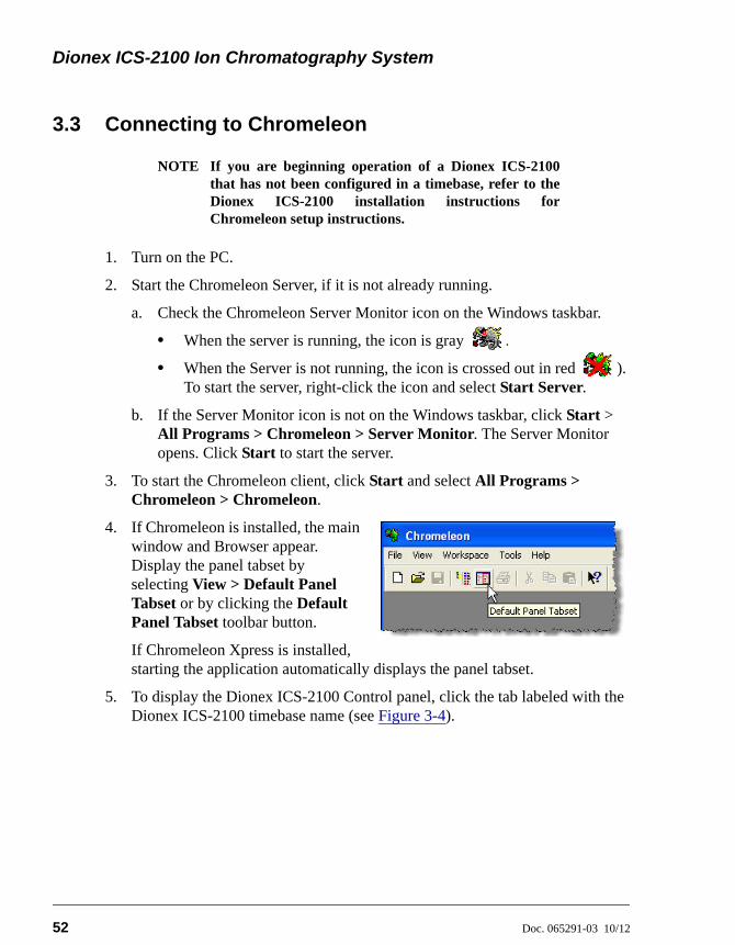
Dionex ICS-2100 Ion Chromatography System
52 Doc. 065291-03 10/12
3.3 Connecting to Chromeleon
NOTE If you are beginning operation of a Dionex ICS-2100that has not been configured in a timebase, refer to theDionex ICS-2100 installation instructions forChromeleon setup instructions.
1. Turn on the PC.
2. Start the Chromeleon Server, if it is not already running.
a. Check the Chromeleon Server Monitor icon on the Windows taskbar.
• When the server is running, the icon is gray .
• When the Server is not running, the icon is crossed out in red ). To start the server, right-click the icon and select Start Server.
b. If the Server Monitor icon is not on the Windows taskbar, click Start > All Programs > Chromeleon > Server Monitor. The Server Monitor opens. Click Start to start the server.
3. To start the Chromeleon client, click Start and select All Programs > Chromeleon > Chromeleon.
4. If Chromeleon is installed, the main window and Browser appear. Display the panel tabset by selecting View > Default Panel Tabset or by clicking the Default Panel Tabset toolbar button.
If Chromeleon Xpress is installed, starting the application automatically displays the panel tabset.
5. To display the Dionex ICS-2100 Control panel, click the tab labeled with the Dionex ICS-2100 timebase name (see Figure 3-4).
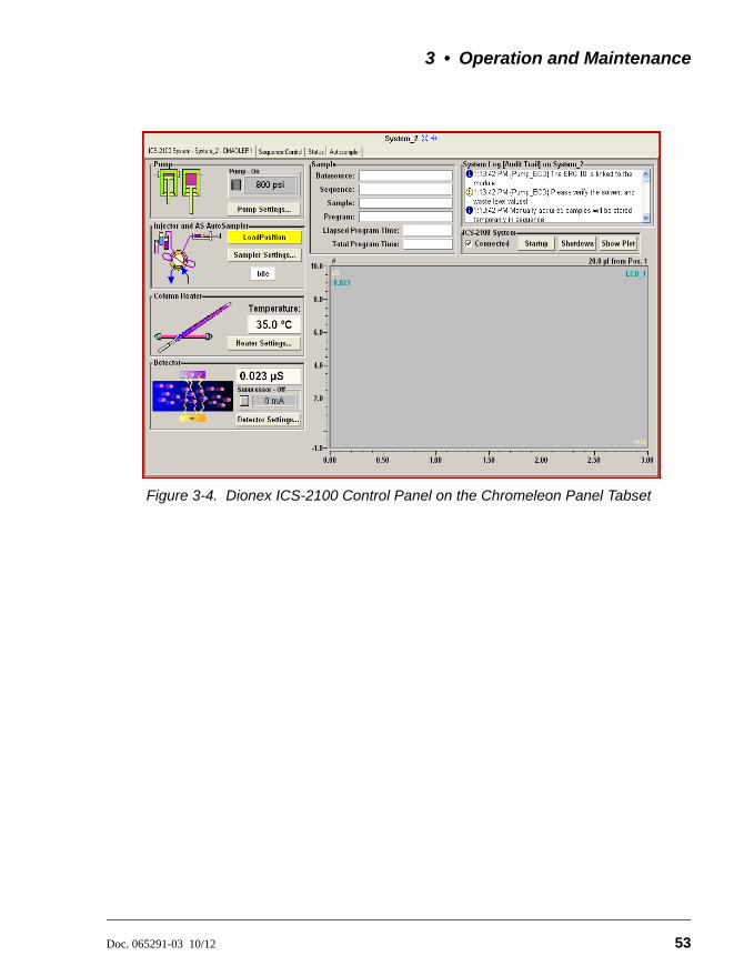
3 • Operation and Maintenance
Doc. 065291-03 10/12 53
Figure 3-4. Dionex ICS-2100 Control Panel on the Chromeleon Panel Tabset
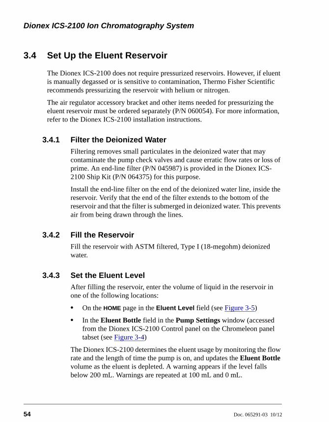
Dionex ICS-2100 Ion Chromatography System
54 Doc. 065291-03 10/12
3.4 Set Up the Eluent Reservoir
The Dionex ICS-2100 does not require pressurized reservoirs. However, if eluent is manually degassed or is sensitive to contamination, Thermo Fisher Scientific recommends pressurizing the reservoir with helium or nitrogen.
The air regulator accessory bracket and other items needed for pressurizing the eluent reservoir must be ordered separately (P/N 060054). For more information, refer to the Dionex ICS-2100 installation instructions.
3.4.1 Filter the Deionized Water
Filtering removes small particulates in the deionized water that may contaminate the pump check valves and cause erratic flow rates or loss of prime. An end-line filter (P/N 045987) is provided in the Dionex ICS-2100 Ship Kit (P/N 064375) for this purpose.
Install the end-line filter on the end of the deionized water line, inside the reservoir. Verify that the end of the filter extends to the bottom of the reservoir and that the filter is submerged in deionized water. This prevents air from being drawn through the lines.
3.4.2 Fill the Reservoir
Fill the reservoir with ASTM filtered, Type I (18-megohm) deionized water.
3.4.3 Set the Eluent Level
After filling the reservoir, enter the volume of liquid in the reservoir in one of the following locations:
• On the HOME page in the Eluent Level field (see Figure 3-5)
• In the Eluent Bottle field in the Pump Settings window (accessed from the Dionex ICS-2100 Control panel on the Chromeleon panel tabset (see Figure 3-4)
The Dionex ICS-2100 determines the eluent usage by monitoring the flow rate and the length of time the pump is on, and updates the Eluent Bottle volume as the eluent is depleted. A warning appears if the level falls below 200 mL. Warnings are repeated at 100 mL and 0 mL.
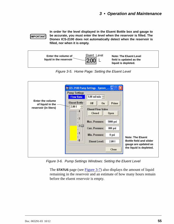
3 • Operation and Maintenance
Doc. 065291-03 10/12 55
The STATUS page (see Figure 3-7) also displays the amount of liquid remaining in the reservoir and an estimate of how many hours remain before the eluent reservoir is empty.
In order for the level displayed in the Eluent Bottle box and gauge tobe accurate, you must enter the level when the reservoir is filled. TheDionex ICS-2100 does not automatically detect when the reservoir isfilled, nor when it is empty.
Figure 3-5. Home Page: Setting the Eluent Level
Figure 3-6. Pump Settings Windows: Setting the Eluent Level
Enter the volume ofliquid in the reservoir
Note: The Eluent Level field is updated as the liquid is depleted.
Enter the volumeof liquid in the
reservoir (in liters)
Note: The Eluent Bottle field and slider gauge are updated as the liquid is depleted.
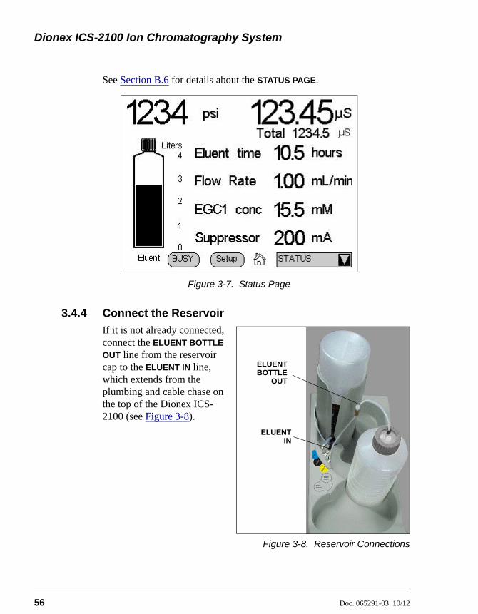
Dionex ICS-2100 Ion Chromatography System
56 Doc. 065291-03 10/12
See Section B.6 for details about the STATUS PAGE.
3.4.4 Connect the Reservoir
If it is not already connected, connect the ELUENT BOTTLE
OUT line from the reservoir cap to the ELUENT IN line, which extends from the plumbing and cable chase on the top of the Dionex ICS-2100 (see Figure 3-8).
Figure 3-8. Reservoir Connections
Figure 3-7. Status Page
ELUENTBOTTLE
OUT
ELUENTIN
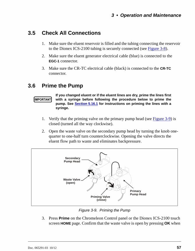
3 • Operation and Maintenance
Doc. 065291-03 10/12 57
3.5 Check All Connections
1. Make sure the eluent reservoir is filled and the tubing connecting the reservoir to the Dionex ICS-2100 tubing is securely connected (see Figure 3-8).
2. Make sure the eluent generator electrical cable (blue) is connected to the EGC-1 connector.
3. Make sure the CR-TC electrical cable (black) is connected to the CR-TC connector.
3.6 Prime the Pump
1. Verify that the priming valve on the primary pump head (see Figure 3-9) is closed (turned all the way clockwise).
2. Open the waste valve on the secondary pump head by turning the knob one-quarter to one-half turn counterclockwise. Opening the valve directs the eluent flow path to waste and eliminates backpressure.
3. Press Prime on the Chromeleon Control panel or the Dionex ICS-2100 touch screen HOME page. Confirm that the waste valve is open by pressing OK when
If you changed eluent or if the eluent lines are dry, prime the lines firstwith a syringe before following the procedure below to prime thepump. See Section 5.16.1 for instructions on priming the lines with asyringe.
Figure 3-9. Priming the Pump
Priming Valve
Waste Valve
PrimaryPump Head
SecondaryPump Head
(open)
(close)
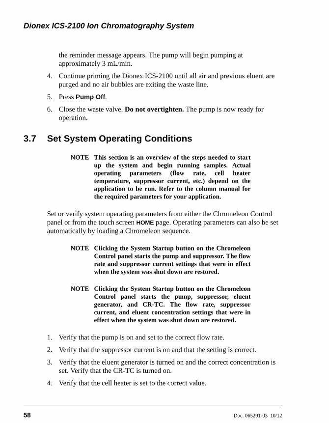
Dionex ICS-2100 Ion Chromatography System
58 Doc. 065291-03 10/12
the reminder message appears. The pump will begin pumping at approximately 3 mL/min.
4. Continue priming the Dionex ICS-2100 until all air and previous eluent are purged and no air bubbles are exiting the waste line.
5. Press Pump Off.
6. Close the waste valve. Do not overtighten. The pump is now ready for operation.
3.7 Set System Operating Conditions
NOTE This section is an overview of the steps needed to startup the system and begin running samples. Actualoperating parameters (flow rate, cell heatertemperature, suppressor current, etc.) depend on theapplication to be run. Refer to the column manual forthe required parameters for your application.
Set or verify system operating parameters from either the Chromeleon Control panel or from the touch screen HOME page. Operating parameters can also be set automatically by loading a Chromeleon sequence.
NOTE Clicking the System Startup button on the ChromeleonControl panel starts the pump and suppressor. The flowrate and suppressor current settings that were in effectwhen the system was shut down are restored.
NOTE Clicking the System Startup button on the ChromeleonControl panel starts the pump, suppressor, eluentgenerator, and CR-TC. The flow rate, suppressorcurrent, and eluent concentration settings that were ineffect when the system was shut down are restored.
1. Verify that the pump is on and set to the correct flow rate.
2. Verify that the suppressor current is on and that the setting is correct.
3. Verify that the eluent generator is turned on and the correct concentration is set. Verify that the CR-TC is turned on.
4. Verify that the cell heater is set to the correct value.
3 • Operation and Maintenance
Doc. 065291-03 10/12 59
5. Verify that the column heater is set to the correct value.
Automatically Turning on the Suppressor and Eluent Generator
You can set up the Dionex ICS-2100 to turn on the suppressor, eluent generator, and CR-TC automatically when the pump is turned on. To do this:
• For the suppressor, select the Automatically turn on with pump option from the SUPPRESSOR page.
• For the eluent generator and CR-TC, select the option from the ELUENT
GENERATOR page.
NOTE The suppressor, eluent generator, and CR-TC arealways turned off automatically when the pump isturned off.
3.8 Equilibrate the System and Verify Operational Status
NOTE You can monitor system functions (conductivity,pressure, cell temperature, etc.) from the ChromeleonControl panel or from the touch screen HOME page.
1. Allow the system to equilibrate. During equilibration, the Chromeleon Control panel displays the background conductivity (the conductivity of the eluent before sample injection) and the system backpressure.
2. Monitor the background conductivity. Refer to the column manual for the appropriate background conductivity for your application.
3. Offset the background and zero the reading by clicking the Autozero button on the Chromeleon Control panel (see Figure 3-4).
4. Monitor the system pressure from the Control panel to make sure it is at the expected pressure for the installed column (refer to the column manual for details) and is stable.
• If the pressure is less than the expected amount, gas may be trapped in the system. To release the gas, remove the pump fitting on the injection valve port, labeled P (2). Allow the air to escape and then reconnect the fitting.
• If the pressure fluctuates by more than about 0.13 MPa (20 psi), prime the pump. See Section 4.4 for additional troubleshooting information.
Dionex ICS-2100 Ion Chromatography System
60 Doc. 065291-03 10/12
• If the pressure is too high, there may be a restriction in the system plumbing. See Section 4.8 for troubleshooting information.
5. Verify that the baseline conductivity is at the expected reading for your application and is stable. In general, it should be <30 S for a system set up for anion analyses and <2 S for a system set up for cation analyses. See Section 4.13 for troubleshooting information if the conductivity is too high. See Section 4.14 if the baseline is drifting or has excessive “noise” (large fluctuations in readings).
6. Verify that the cell heater is at the set point and is stable. The temperature is at equilibrium when the Set Temperature and the Current Temperature readings on the Control panel are the same, or when the “=” symbol is displayed next to the Column Heater temperature on the HOME page.
7. Verify that the column heater temperature is at the set point and stable. The temperature is at equilibrium when the Set Temperature and the Current Temperature readings on the Control panel are the same, or when the “=” symbol is displayed next to the Column Heater temperature on the HOME page.
The system is now ready for sample processing.
3.9 Prepare Samples
NOTE Sample preparation can be performed while the systemis equilibrating.
3.9.1 Collecting and Storing Samples
Collect samples in high density polyethylene containers that have been thoroughly cleaned with deionized (DI) water. Do not clean containers with strong acids or detergents because these can leave traces of ions on the container walls. The ions may interfere with the analysis.
If samples will not be analyzed on the day they are collected, filter them through clean 0.45 m filters immediately after collection; otherwise, bacteria in the samples may cause the ionic concentrations to change over time. Refrigerating the samples at 4C (39 F) will reduce, but not eliminate, bacterial growth.
3 • Operation and Maintenance
Doc. 065291-03 10/12 61
Analyze samples containing nitrite or sulfite as soon as possible. Nitrite oxidizes to nitrate, and sulfite to sulfate, thus increasing the measured concentrations of these ions in the sample. In general, samples that do not contain nitrite or sulfite can be refrigerated for at least one week with no significant changes in anion concentrations.
3.9.2 Pretreating Samples
Analyze rainwater, drinking water, and air particulate leach solutions directly with no sample preparation (other than filtering and possibly diluting).
Filter groundwater and wastewater samples through 0.45 m filters before injection, unless samples were filtered after collection.
Before injection, pretreat samples that may contain high concentrations of interfering substances by putting them through Dionex OnGuard™ cartridges. Refer to Installation and Troubleshooting Guide for OnGuard Cartridges (Document No. 032943) for instructions.
3.9.3 Diluting Samples
Because the concentrations of ionic species in different samples can vary widely from sample to sample, no single dilution factor can be recommended for all samples of one type. In some cases (for example, many water samples), concentrations are so low that dilution is not necessary.
Use eluent or ASTM filtered, Type I (18-megohm) deionized water to dilute the sample. When using carbonate eluents, diluting with eluent minimizes the effect of the water dip at the beginning of the chromatogram. If you dilute the sample with eluent, also use eluent from the same lot to prepare the calibration standards. This is most important for fluoride and chloride, which elute near the water dip.
To improve the accuracy of early eluting peak determinations, such as fluoride, at concentrations below 50 ppb, dilute standards in eluent or spike the samples with concentrated eluent to minimize the water dip. For example, spike a 100 mL sample with 1.0 mL of a 100 X eluent concentrate.
Dionex ICS-2100 Ion Chromatography System
62 Doc. 065291-03 10/12
3.10 Loading and Injecting Samples
NOTE Samples can be injected using either the standardinjection valve or the optional auxiliary valve, ifinstalled. For more information, see the ChromeleonHelp or user’s manual.
The two techniques for loading samples into the sample loop are: (1) with an autosampler or (2) with a syringe or vacuum syringe through the injection port on the Dionex ICS-2100 front door.
For autosampler injections, the injection port tubing is disconnected from the Dionex ICS-2100 injection valve and replaced by the autosampler outlet tubing. Other setup requirements depend upon the model of autosampler.
Setup for a Dionex AS Autosampler
To use a Dionex AS Autosampler with the Dionex ICS-2100, the following requirements must be met:
• The Dionex ICS-2100 injection valve (or the auxiliary valve, if installed) must be specified as the injection valve and must be linked to the Dionex AS in the Chromeleon timebase.
• An injection valve should not be installed in the AS.
See the Dionex ICS-2100 installation instructions for Dionex AS connection instructions.
NOTE The Dionex ICS-2100 and the Dionex AS can be set upfor stand-alone (front panel) operation. This requires aTTL cable connection between the Dionex ICS-2100 andthe AS. See Section C.3 for stand-alone setupinstructions.
Setup for a Dionex AS-DV Autosampler
To use a Dionex AS-DV Autosampler with the Dionex ICS-2100, the following requirements must be met:
• The Dionex ICS-2100 injection valve must be linked to the Dionex AS-DV in the Chromeleon timebase.
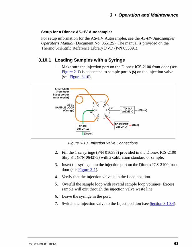
3 • Operation and Maintenance
Doc. 065291-03 10/12 63
Setup for a Dionex AS-HV Autosampler
For setup information for the AS-HV Autosampler, see the AS-HV Autosampler Operator’s Manual (Document No. 065125). The manual is provided on the Thermo Scientific Reference Library DVD (P/N 053891).
3.10.1 Loading Samples with a Syringe
1. Make sure the injection port on the Dionex ICS-2100 front door (see Figure 2-1) is connected to sample port S (5) on the injection valve (see Figure 3-10).
2. Fill the 1 cc syringe (P/N 016388) provided in the Dionex ICS-2100 Ship Kit (P/N 064375) with a calibration standard or sample.
3. Insert the syringe into the injection port on the Dionex ICS-2100 front door (see Figure 2-1).
4. Verify that the injection valve is in the Load position.
5. Overfill the sample loop with several sample loop volumes. Excess sample will exit through the injection valve waste line.
6. Leave the syringe in the port.
7. Switch the injection valve to the Inject position (see Section 3.10.4).
Figure 3-10. Injection Valve Connections
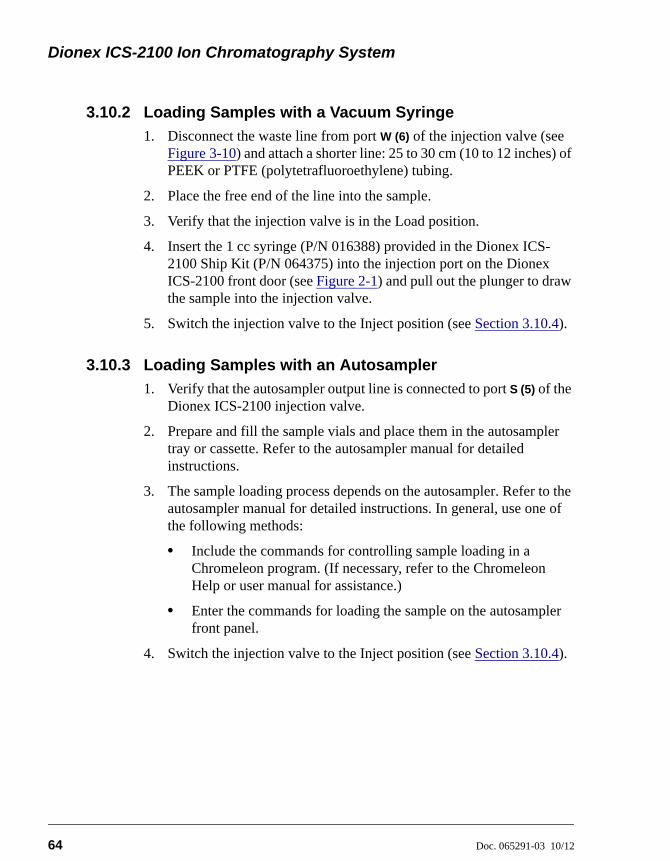
Dionex ICS-2100 Ion Chromatography System
64 Doc. 065291-03 10/12
3.10.2 Loading Samples with a Vacuum Syringe
1. Disconnect the waste line from port W (6) of the injection valve (see Figure 3-10) and attach a shorter line: 25 to 30 cm (10 to 12 inches) of PEEK or PTFE (polytetrafluoroethylene) tubing.
2. Place the free end of the line into the sample.
3. Verify that the injection valve is in the Load position.
4. Insert the 1 cc syringe (P/N 016388) provided in the Dionex ICS-2100 Ship Kit (P/N 064375) into the injection port on the Dionex ICS-2100 front door (see Figure 2-1) and pull out the plunger to draw the sample into the injection valve.
5. Switch the injection valve to the Inject position (see Section 3.10.4).
3.10.3 Loading Samples with an Autosampler
1. Verify that the autosampler output line is connected to port S (5) of the Dionex ICS-2100 injection valve.
2. Prepare and fill the sample vials and place them in the autosampler tray or cassette. Refer to the autosampler manual for detailed instructions.
3. The sample loading process depends on the autosampler. Refer to the autosampler manual for detailed instructions. In general, use one of the following methods:
• Include the commands for controlling sample loading in a Chromeleon program. (If necessary, refer to the Chromeleon Help or user manual for assistance.)
• Enter the commands for loading the sample on the autosampler front panel.
4. Switch the injection valve to the Inject position (see Section 3.10.4).
3 • Operation and Maintenance
Doc. 065291-03 10/12 65
3.10.4 Injecting Samples
After loading the sample in the sample loop, use one of the following methods to switch the injection valve to the Inject position:
• Manually: Click the Inject button on the Chromeleon Control panel (see Figure 3-4) or touch the Inject button on the HOME page.
• Automatically: Include the Inject command in a Chromeleon program. (If necessary, refer to the Chromeleon Help or user manual for assistance.)
3.11 Processing Samples
Samples can be run manually (one at a time) or else they can be grouped and run automatically in batches.
3.11.1 Manual Sample Processing
To process samples manually, select operating parameters and commands from the touch screen pages, or from the Chromeleon menu bar, toolbars, and Control panel. Commands are executed as soon as they are entered.
NOTE When you run samples manually from the frontpanel (without using Chromeleon), the data is savedonly temporarily in the Dionex ICS-2100 memory.For a permanent record of the data, connect arecording device (chart recorder, integrator, etc.) tothe analog output. For output connectioninstructions, refer to the Dionex ICS-2100installation instructions.
1. Complete the instructions in Section 3.2 through Section 3.8 to prepare the Dionex ICS-2100 for operation and to prepare the sample for processing.
2. Load the sample, using a syringe, vacuum syringe, or autosampler (see Section 3.10).
3. In Chromeleon, select Control > Acquisition On. Chromeleon records the signal supplied by the detector and displays the signal plot on the Control panel.
Dionex ICS-2100 Ion Chromatography System
66 Doc. 065291-03 10/12
4. Click the Autozero button on the Control panel or the touch screen HOME page.
5. Inject the sample (see Section 3.10.4).
6. In Chromeleon, monitor the chromatogram on the Control panel and select Control > Acquisition Off when sample data is collected.
NOTE Data from Chromeleon manual processing issaved in the MANUAL sequence folder underthe local datasource. This data is overwritteneach time a new manual sample is processed. Tosave the data from a manual run, select theMANUAL folder, select File > Save As, andenter a new name for the sequence.
7. If you are controlling the Dionex ICS-2100 from the touch screens, select the PLOT button on the HOME page to view a plot of the conductivity data.
3.11.2 Automatic (Batch) Sample Processing
You can use Chromeleon or Chromeleon Xpress to create a list of samples (a sequence) to be processed automatically. For each sample, the sequence includes the following:
• A program with commands and parameters for controlling the Dionex ICS-2100 and autosampler (if used), and for acquiring sample data.
• A quantification method for peak identification and area determination.
• Additional sample processing parameters (sample name, sample type, injection volume, etc.).
After creating the sequence, you can start batch processing.
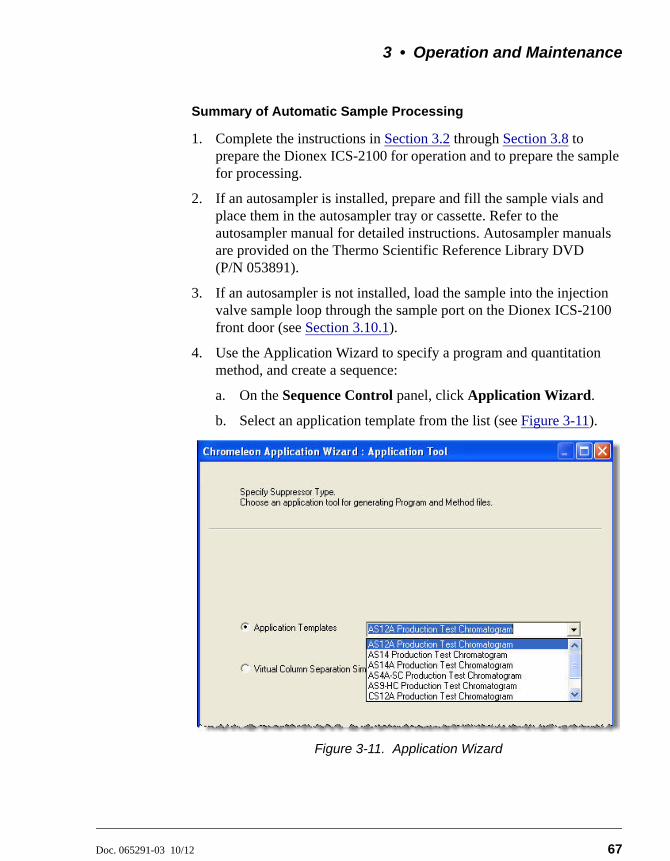
3 • Operation and Maintenance
Doc. 065291-03 10/12 67
Summary of Automatic Sample Processing
1. Complete the instructions in Section 3.2 through Section 3.8 to prepare the Dionex ICS-2100 for operation and to prepare the sample for processing.
2. If an autosampler is installed, prepare and fill the sample vials and place them in the autosampler tray or cassette. Refer to the autosampler manual for detailed instructions. Autosampler manuals are provided on the Thermo Scientific Reference Library DVD (P/N 053891).
3. If an autosampler is not installed, load the sample into the injection valve sample loop through the sample port on the Dionex ICS-2100 front door (see Section 3.10.1).
4. Use the Application Wizard to specify a program and quantitation method, and create a sequence:
a. On the Sequence Control panel, click Application Wizard.
b. Select an application template from the list (see Figure 3-11).
Figure 3-11. Application Wizard
Dionex ICS-2100 Ion Chromatography System
68 Doc. 065291-03 10/12
c. Click Next > and select the in a new sequence via Sequence Wizard option.
d. Click Next > to go to the Sequence Wizard.
e. Complete the steps in the Sequence Wizard, adding the desired number of samples and standards to the list. For help, click the Help button on the Sequence Wizard page.
After you click Finish, a sequence is created and a program appropriate for the selected application is copied to the sequence. If you are using Chromeleon, a quantification method is also copied to the sequence.
5. Load the sequence and start batch processing:
a. On the Sequence Control panel, click Load Sequence.
b. Select the sequence created in Step 4 and click Open.
c. Click Start Batch.
3.12 Maintenance
This section describes routine maintenance procedures that users may perform. All other maintenance procedures must be performed by Thermo Fisher Scientific personnel.
As Needed
• Regularly check the eluent reservoir and refill when needed.
Daily
• Check the Dionex ICS-2100 component panel (see Figure 2-8) for leaks or spills. Wipe up spills. Isolate and repair leaks (see Section 4.3). Rinse off any dried eluent with deionized water.
• Check the waste container daily and empty when needed.
Weekly
• Once a week, check fluid lines for crimping or discoloration. Replace any pinched lines. Replace damaged lines.
• Check the junctions between the pump heads and the pump casting for evidence of liquid leaks. If the piston seal wash tubing is not connected, check
3 • Operation and Maintenance
Doc. 065291-03 10/12 69
the drain tubes at the rear of the pump heads for evidence of moisture. Normal friction and wear may gradually result in small liquid leaks around the piston seal. If unchecked, these leaks can gradually contaminate the piston housing, causing the pump to operate poorly. If leaks occur, replace the piston seals (see Section 5.7).
• Check the end-line filter (P/N 045987) and change if needed. When new, end-line filters are pure white. If the system is in continuous operation, change the end-line filter weekly, or whenever it becomes discolored. Replace the filter more often if bacterial buildup is visible or if the eluent does not contain solvent.
NOTE It is especially important to regularly replace end-linefilters when using aqueous eluents, which maycontaminate the filter with bacteria or algae. Thebacterial buildup may not be visible.
Every Six Months
• Calibrate the cell (see Section 5.1.3).
• Calibrate the vacuum degas assembly (see Section 5.1.5).
• Replace the pump piston rinse seals and piston seals (see Section 5.7).
Yearly
• Thermo Fisher Scientific recommends performing preventive maintenance annually, as well as before scheduled Performance Qualification tests. A Dionex ICS-2100 Preventive Maintenance Kit (P/N 057954) is available for this purpose.
• Rebuild the auxiliary valve, if installed (see Section 5.4).
• If a Dionex AS Autosampler is installed, perform the preventive maintenance procedure. The Dionex AS Preventive Maintenance Kit (P/N 060581) is available for this purpose.
• If a Dionex AS-DV Autosampler is installed, replace the tip and tubing. The Dionex AS-DV Preventive Maintenance Kit (P/N 055647) contains all of the components required to replace the sampling tip and the tubing between the tip and the injection valve. Instructions are included with the kit.
Dionex ICS-2100 Ion Chromatography System
70 Doc. 065291-03 10/12
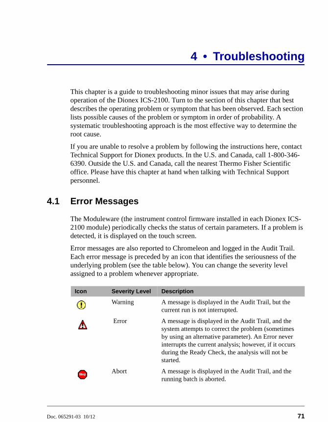
Doc. 065291-03 10/12 71
4 • Troubleshooting
This chapter is a guide to troubleshooting minor issues that may arise during operation of the Dionex ICS-2100. Turn to the section of this chapter that best describes the operating problem or symptom that has been observed. Each section lists possible causes of the problem or symptom in order of probability. A systematic troubleshooting approach is the most effective way to determine the root cause.
If you are unable to resolve a problem by following the instructions here, contact Technical Support for Dionex products. In the U.S. and Canada, call 1-800-346-6390. Outside the U.S. and Canada, call the nearest Thermo Fisher Scientific office. Please have this chapter at hand when talking with Technical Support personnel.
4.1 Error Messages
The Moduleware (the instrument control firmware installed in each Dionex ICS-2100 module) periodically checks the status of certain parameters. If a problem is detected, it is displayed on the touch screen.
Error messages are also reported to Chromeleon and logged in the Audit Trail. Each error message is preceded by an icon that identifies the seriousness of the underlying problem (see the table below). You can change the severity level assigned to a problem whenever appropriate.
Icon Severity Level Description
Warning A message is displayed in the Audit Trail, but the current run is not interrupted.
Error A message is displayed in the Audit Trail, and the system attempts to correct the problem (sometimes by using an alternative parameter). An Error never interrupts the current analysis; however, if it occurs during the Ready Check, the analysis will not be started.
Abort A message is displayed in the Audit Trail, and the running batch is aborted.

Dionex ICS-2100 Ion Chromatography System
72 Doc. 065291-03 10/12
The table below lists the most frequently observed Dionex ICS-2100 error messages. For troubleshooting assistance, refer to the page indicated in the table.
Alarms and Error Conditions See
Auxiliary power supply disconnected page 74
Auxiliary power supply over current page 74
Auxiliary power supply over voltage page 75
Auxiliary power supply stopped for zero flow page 75
Column heater exceeds safe temperature page 75
Column heater open circuit page 76
Column heater short circuit page 76
CR-TC over current page 76
CR-TC stopped for zero flow rate page 77
Degas calibration failed page 77
EGC board not present page 77
EGC-1 calibration error page 78
EGC-1 disconnected error page 78
EGC-1 invalid concentration page 79
EGC-1 invalid concentration vs. flow rate page 79
EGC-1 invalid flow rate page 79
EGC-1 over current page 79
EGC-1 over voltage page 80
EGC-2 calibration error page 78
EGC-2 disconnected error page 78
EGC-2 invalid concentration vs. flow rate page 79
EGC-2 invalid flow rate page 79
EGC-2 over current page 79
EGC-2 over voltage page 80
Hardware not present page 80
Leak sensor wet page 80
Load/Inject valve error page 81
Option not installed page 81
Table 4-5. Alarms and Error Messages Summary
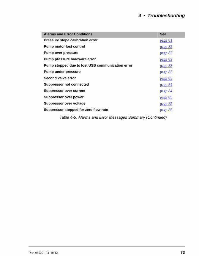
4 • Troubleshooting
Doc. 065291-03 10/12 73
Pressure slope calibration error page 81
Pump motor lost control page 82
Pump over pressure page 82
Pump pressure hardware error page 82
Pump stopped due to lost USB communication error page 83
Pump under pressure page 83
Second valve error page 83
Suppressor not connected page 84
Suppressor over current page 84
Suppressor over power page 85
Suppressor over voltage page 85
Suppressor stopped for zero flow rate page 85
Alarms and Error Conditions See
Table 4-5. Alarms and Error Messages Summary (Continued)
Dionex ICS-2100 Ion Chromatography System
74 Doc. 065291-03 10/12
4.2 Troubleshooting Error Messages
This error occurs when the auxiliary power supply is configured as active, but no device is connected.
To troubleshoot:
1. Connect the cable for the auxiliary device to the EGC-2 power supply connector.
2. If there is no auxiliary device, open the Chromeleon Server Configuration program and remove this option from the Dionex ICS-2100 timebase.
This error occurs when the device connected to the auxiliary power supply is attempting to draw more current than is allowed (200 mA) or is 20% higher than the set current.
To troubleshoot:
1. Check the cable connecting the device to the power supply for damage or a faulty connection.
2. If the error persists, refer to the manual provided by the device vendor for assistance.
AUXILIARY POWER SUPPLY DISCONNECTED
AUXILIARY POWER SUPPLY OVER CURRENT
4 • Troubleshooting
Doc. 065291-03 10/12 75
This error occurs when the device connected to the auxiliary power supply is attempting to operate at a higher voltage than is allowed (35 V).
To troubleshoot:
1. Check the cable connecting the device to the power supply for damage or a faulty connection.
2. If the error persists, refer to the manual provided by the device vendor for assistance.
When the pump flow stops, the auxiliary power supply automatically turns off (to prevent damage to the electrolytic device) and this error occurs.
To troubleshoot:
If the pump stopped unexpectedly, see Section 4.6 for pump troubleshooting information.
This error occurs when the column heater temperature is higher than the maximum allowed. This error may occur if the Dionex ICS-2100 is operating in an extreme environment (greater than 40 °C (104 °F)).
To troubleshoot:
Refer to Section A.3 for environmental specifications.
AUXILIARY POWER SUPPLY OVER VOLTAGE
AUXILIARY POWER SUPPLY STOPPED FOR ZERO FLOW RATE ERROR
COLUMN HEATER EXCEEDS SAFE TEMPERATURE
Dionex ICS-2100 Ion Chromatography System
76 Doc. 065291-03 10/12
This error occurs when the column heater is unplugged from the component panel.
To troubleshoot:
1. Check that the column heater is plugged into the component panel.
2. If the error persists, the column heater may be faulty. Replace the column heater (see Section 5.12).
This error occurs when there is a short circuit on the thermistor input used to measure the column heater temperature. This error indicates a faulty column heater.
To troubleshoot:
Replace the column heater (see Section 5.12).
This error occurs when the current applied to the CR-TC exceeds the maximum current allowed.
To troubleshoot:
1. Check the CR-TC cable connection.
2. If the error persists, contact Thermo Fisher Scientific for assistance. There may be a malfunction in the CR-TC control electronics.
COLUMN HEATER OPEN CIRCUIT
COLUMN HEATER SHORT CIRCUIT
CR-TC OVER CURRENT ERROR
4 • Troubleshooting
Doc. 065291-03 10/12 77
This message appears when you click the Shutdown button on the Chromeleon Control panel. The message also appears when you turn off the pump flow while the EGC current (and CR-TC) are on. The CR-TC is automatically turned off.
To troubleshoot:
If the pump stopped unexpectedly, see Section 4.6 for pump troubleshooting information.
This error occurs when the degas vacuum does not reach the expected level during calibration.
To troubleshoot:
1. Retry the calibration.
2. If calibration still fails, the vacuum degas assembly may need to be replaced. Contact Thermo Fisher Scientific for assistance.
This error occurs if Chromeleon sends a command to the IC related to the eluent generator, but the eluent generator controller board is either not installed or the Dionex ICS-2100 does not recognize the installed board.
To troubleshoot:
Contact Thermo Fisher Scientific for assistance. The electronics components cannot be serviced by the user.
CR-TC STOPPED FOR ZERO FLOW RATE
DEGAS CALIBRATION FAILED
EGC BOARD NOT PRESENT
Dionex ICS-2100 Ion Chromatography System
78 Doc. 065291-03 10/12
This error occurs if the measured current is outside the expected range when running the eluent generator calibration procedure.
To troubleshoot:
1. Review the procedure to verify that you set up the Dionex ICS-2100 correctly and then rerun the calibration.
2. If the error message reappears, contact Thermo Fisher Scientific for assistance.
This error occurs when Chromeleon sends a command to set an eluent generator parameter when the EGC is disconnected. The error also can occur if you attempt to run the EGC verification test when the EGC is disconnected.
To troubleshoot:
1. Verify that the Dionex EluGen cartridge cable is connected to the EGC-1
connector on the Dionex ICS-2100 top cover (see Figure 2-7).
2. If the error persists, contact Thermo Fisher Scientific for assistance. There may be a malfunction in the EGC control electronics.
EGC-1 CALIBRATION ERROR
EGC-2 CALIBRATION ERROR
EGC-1 DISCONNECTED ERROR
EGC-2 DISCONNECTED ERROR
4 • Troubleshooting
Doc. 065291-03 10/12 79
The maximum eluent concentration that can be set for a particular application depends on the suppressor type, the EGC type, and the flow rate. This error occurs when the selected concentration is too high for the current flow rate.
To troubleshoot:
Refer to the column manual, which is included on the Thermo Scientific Reference Library DVD (P/N 053891), for the concentration of eluent to use with your application. Reset the eluent concentration and/or the flow rate to the recommended values.
This error occurs if the flow rate is set to a value not supported by the eluent generator. The Dionex ICS-2100 allows a flow rate range of 0.00 to 5.00 mL/min without an eluent generator. With an eluent generator, the allowed range is 0.10 to 3.00 mL/min. The recommended operating range is 0.40 to 2.00 mL/min.
To troubleshoot:
Set the flow rate to a value within the allowed range.
This error occurs when the current applied to the Dionex EluGen cartridge exceeds the maximum current allowed. Under these conditions, the EGC current is turned off to prevent damage to the EGC. This error may occur if the liquid flow to the cartridge is interrupted.
To troubleshoot:
See Section 4.6 for troubleshooting when there is no flow from the pump.
EGC-1 INVALID CONCENTRATION VS. FLOW RATE ERROR
EGC-2 INVALID CONCENTRATION VS. FLOW RATE ERROR
EGC-1 INVALID FLOW RATE ERROR
EGC-2 INVALID FLOW RATE ERROR
EGC-1 OVER CURRENT
EGC-2 OVER CURRENT
Dionex ICS-2100 Ion Chromatography System
80 Doc. 065291-03 10/12
This error occurs when the current applied to the Dionex EluGen cartridge exceeds the maximum current allowed. The EGC current is turned off to prevent damage to the EGC. This error may occur if the liquid flow to the cartridge is interrupted.
To troubleshoot:
See Section 4.6 for troubleshooting when there is no flow from the pump.
This error indicates a problem in the Dionex ICS-2100 electronics.
To troubleshoot:
Contact Thermo Fisher Scientific for assistance. The Dionex ICS-2100 electronics components cannot be serviced by the user.
The leak sensor is installed in the drip tray at the bottom of the component panel (see Figure 2-8). If liquid accumulates in the tray, the sensor signals the problem and this error message appears.
To troubleshoot:
1. Locate the source of the leak by visually inspecting the tubing, fittings, and components on the component panel. Refer to Section 4.3.
2. Tighten fittings or replace tubing and fittings as required. Refer to Section 4.3 for detailed troubleshooting of various types of leaks.
3. After fixing the leak, dry the drip tray thoroughly to prevent the leak sensor from triggering additional error messages.
EGC-1 OVER VOLTAGE
EGC-2 OVER VOLTAGE
HARDWARE NOT PRESENT
LEAK SENSOR WET
4 • Troubleshooting
Doc. 065291-03 10/12 81
If the injection valve fails to switch position within 1 second of being toggled, the Dionex ICS-2100 Moduleware reports an error to Chromeleon and this error message appears.
To troubleshoot:
1. If a sequence is being executed, terminate the sequence by selecting Batch > Stop in Chromeleon.
2. Try to toggle the valve from Load to Inject by clicking the Load and Inject buttons on the Dionex ICS-2100 Control panel in Chromeleon or on the touch screen HOME page.
3. Turn off the Dionex ICS-2100 power briefly and then restart.
4. If the problem persists, repeat Step 2.
5. If the problem persists, contact Thermo Fisher Scientific for assistance.
This error occurs if a command is issued to control an option that is not installed.
To troubleshoot:
Check the Chromeleon Server Configuration program to verify that the option is enabled.
This error occurs if you try to calibrate the pressure slope when the pressure is less than 3 MPa (500 psi).
To troubleshoot:
Contact Thermo Fisher Scientific for assistance.
LOAD/INJECT VALVE ERROR
OPTION NOT INSTALLED
PRESSURE SLOPE CALIBRATION ERROR
Dionex ICS-2100 Ion Chromatography System
82 Doc. 065291-03 10/12
This error indicates a problem in the pump controller electronics.
To troubleshoot:
Contact Thermo Fisher Scientific for assistance. The Dionex ICS-2100 electronics components cannot be serviced by the user.
This error indicates a problem in the pump controller electronics.
To troubleshoot:
Contact Thermo Fisher Scientific for assistance. The Dionex ICS-2100 electronics components cannot be serviced by the user.
If the system pressure exceeds the set limit for at least 0.5 second, this error message appears and the pump stops. Pressure limits can be set in the Chromeleon Server Configuration or in the control program. The limits can also be set on the touch screen PUMP page (see Section B.7.1).
To troubleshoot:
1. Check for blockages in the liquid lines by working your way backward from the cell to the pump. See Section 2.2 for the system flow schematics.
2. Check that the flow rate is set to the correct value.
3. Check that the high pressure limit is set to the correct value.
4. Restart the pump.
PUMP MOTOR LOST CONTROL
PUMP PRESSURE HARDWARE ERROR
PUMP OVER PRESSURE
4 • Troubleshooting
Doc. 065291-03 10/12 83
This error occurs if the Dionex ICS-2100 loses communication with Chromeleon.
To troubleshoot:
Verify that the USB cable is connected correctly from the Dionex ICS-2100 rear panel to the Chromeleon PC.
If the system pressure falls below the low pressure limit, the pump stops and this error message appears. Pressure limits can be set in the Chromeleon Server Configuration or in the control program. The limits can also be set on the touch screen PUMP page (see Section B.7.1).
To troubleshoot:
1. Make sure the eluent reservoir is full.
2. Check for liquid leaks (see Section 4.3).
3. Check that the waste valve is closed.
4. Prime the pump (see Section 5.16).
5. Restart the pump.
If the auxiliary valve fails to switch position within 1 second of being toggled, the Dionex ICS-2100 Moduleware reports an error to Chromeleon and this error message appears.
To troubleshoot:
1. If a sequence is being executed, terminate the sequence by selecting Batch > Stop in Chromeleon.
PUMP STOPPED DUE TO LOST USB COMMUNICATION ERROR
PUMP UNDER PRESSURE
SECOND VALVE ERROR
Dionex ICS-2100 Ion Chromatography System
84 Doc. 065291-03 10/12
2. Try to toggle the valve from position A to position B by clicking the corresponding buttons on the Dionex ICS-2100 Control panel in Chromeleon (or by clicking the Valve_2 commands under Pump_ECD in the Commands dialog box).
3. Turn off the Dionex ICS-2100 power briefly and then restart.
4. If the problem persists, repeat Step 2.
5. If the problem persists, contact Thermo Fisher Scientific for assistance.
This error occurs if you turn on the suppressor and the Dionex ICS-2100 cannot establish a connection with the suppressor.
To troubleshoot:
1. Check the suppressor cable connection (see Section 5.11).
2. If the error persists, contact Thermo Fisher Scientific for assistance. There may be a problem in the suppressor controller electronics. The Dionex ICS-2100 electronics components cannot be serviced by the user.
This error may be caused by an expended or dirty suppressor or by a malfunction in the suppressor controller electronics.
To troubleshoot:
1. Follow the instructions in the suppressor manual to regenerate the suppressor. Suppressor manuals are included on the Thermo Scientific Reference Library DVD (P/N 053891).
2. Follow the instructions in the suppressor manual to clean the suppressor.
3. If a malfunction in the suppressor controller is suspected, contact Thermo Fisher Scientific for assistance. The Dionex ICS-2100 electronics components cannot be serviced by the user.
SUPPRESSOR NOT CONNECTED
SUPPRESSOR OVER CURRENT
4 • Troubleshooting
Doc. 065291-03 10/12 85
This error occurs when, in order to maintain the selected current, the Dionex ICS-2100 is required to apply a higher voltage than the suppressor can support.
To troubleshoot:
1. Reduce the flow rate.
2. Rehydrate the suppressor. Refer to the suppressor manual for instructions. Suppressor manuals are included on the Thermo Scientific Reference Library DVD (P/N 053891).
3. If the error persists, replace the suppressor (see Section 5.11).
This error occurs if you turn on the suppressor but the Dionex ICS-2100 cannot establish a connection with the suppressor.
To troubleshoot:
1. Check the suppressor cable connection (see Section 5.11).
2. If the error persists, replace the suppressor (see Section 5.11).
This error message appears when you click the Shutdown button on the Dionex ICS-2100 Control panel in Chromeleon. The message also appears anytime you turn off the pump flow while the suppressor is on. The suppressor is automatically turned off to prevent damage to the suppressor.
To troubleshoot:
• If the pump stopped unexpectedly, see Section 4.6 for pump troubleshooting information.
SUPPRESSOR OVER POWER
SUPPRESSOR OVER VOLTAGE
SUPPRESSOR STOPPED FOR ZERO FLOW RATE
Dionex ICS-2100 Ion Chromatography System
86 Doc. 065291-03 10/12
4.3 Liquid Leaks
• Leaking fitting
Locate the source of the leak. Tighten or, if necessary, replace the liquid line connection (see Section 5.3). Refer to Installation of Dionex Liquid Line Fittings (Document No. 031432) for tightening requirements. The manual is included on the Thermo Scientific Reference Library DVD (P/N 053891).
• Broken liquid line
Replace the line and fittings with the same length and internal diameter tubing (see Section 5.3).
• Blocked or improperly installed line
Make sure the lines are not crimped or otherwise blocked. Also, if the blocked line is a waste line, make sure it is not elevated at any point after it exits the Dionex ICS-2100. If a line is blocked, replace it (see Section 5.2).
• Loose pump check valve
1. Make sure the check valves are firmly seated in the pump head. If they are not, tighten them carefully with an open-end wrench just until the leak stops.
2. If the leak persists, replace the check valve (see Section 5.6).
• Leaking seal wash port
Leaking from the seal wash port indicates a leaking piston seal. Replace the seal (see Section 5.7).
• Damaged pump piston seal
1. Replace the piston seal (see Section 5.7).
2. If the leak persists, replace the piston (see Section 5.8).
• Pump head not tight against casting
Carefully tighten the pump head mounting nuts just until the leak stops. DO NOT OVERTIGHTEN!
4 • Troubleshooting
Doc. 065291-03 10/12 87
• Leaking pressure transducer
1. Make sure the liquid line connections into the pressure transducer are tight. Refer to Installation of Dionex Liquid Line Fittings (Document No. 031432) for tightening requirements. The manual is included on the Thermo Scientific Reference Library DVD (P/N 053891). Replace any damaged fittings.
2. If the pressure transducer continues to leak, contact Thermo Fisher Scientific for assistance. The pressure transducer cannot be serviced by the user.
• Leaking pump head waste valve
Make sure the waste valve is closed. To close the valve, turn the knob clockwise, and tighten fingertight. DO NOT OVERTIGHTEN! Overtightening may damage the valve and the pump head.
If the leak persists, replace the waste valve O-ring (see Section 5.9).
• Leaking suppressor
Refer to the suppressor manual for troubleshooting procedures. Suppressor manuals are included on the Thermo Scientific Reference Library DVD (P/N 053891).
• Leaking injection valve or auxiliary valve
1. Make sure the liquid line connections to the transducer are tight. Refer to Installation of Dionex Liquid Line Fittings (Document No. 031432) for tightening requirements. The manual is included on the Thermo Scientific Reference Library DVD (P/N 053891). Replace any damaged fittings.
2. Liquid leaks from behind the valve stator may indicate a scratched rotor seal. Rebuild the valve (see Section 5.4).
• Leaking detector cell
1. Check the waste lines for blockage; trapped particles can plug the lines and cause a restriction and/or leak. If necessary, clear the waste lines by reversing the direction of flow.
2. Make sure the plumbing downstream from the cell is clear; a blockage may overpressurize the cell, causing it to leak. If the problem continues, contact Thermo Fisher Scientific for assistance.
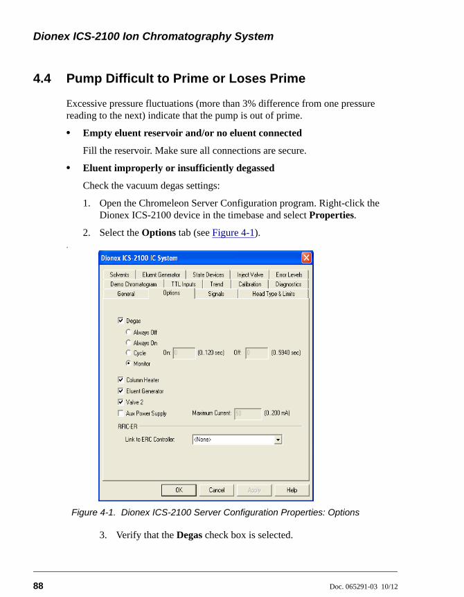
Dionex ICS-2100 Ion Chromatography System
88 Doc. 065291-03 10/12
4.4 Pump Difficult to Prime or Loses Prime
Excessive pressure fluctuations (more than 3% difference from one pressure reading to the next) indicate that the pump is out of prime.
• Empty eluent reservoir and/or no eluent connected
Fill the reservoir. Make sure all connections are secure.
• Eluent improperly or insufficiently degassed
Check the vacuum degas settings:
1. Open the Chromeleon Server Configuration program. Right-click the Dionex ICS-2100 device in the timebase and select Properties.
2. Select the Options tab (see Figure 4-1)..
Figure 4-1. Dionex ICS-2100 Server Configuration Properties: Options
3. Verify that the Degas check box is selected.
4 • Troubleshooting
Doc. 065291-03 10/12 89
4. Check the Degas settings. Select either the Monitor option or the Cycle option. If you select Cycle, set the time On to 30 seconds and the time Off to 600 seconds. If Cycle is already selected, try increasing the time on or decreasing the time off.
NOTE Degas options can also be selected from thetouch screen PUMP page (see Section B.7).
• End-line filter is dirty or clogged
When new, end-line filters (P/N 045987) are pure white. If the system is in continuous operation, change the end-line filter weekly, or whenever it becomes discolored. Replace the filter more often if bacterial buildup is visible or if the eluent does not contain solvent.
NOTE It is especially important to regularly replace end-linefilters when using aqueous eluents, which maycontaminate the filter with bacteria or algae. Thebacterial buildup may not be visible.
• Blockages in inlet tubing
Kinked or clogged tubing causes the pump to be “starved” for eluent. Replace the tubing and fittings (see Section 5.3).
• Dirty check valve
Clean or replace the pump check valve (see Section 5.6).
• Liquid leaks at junction between pump head and pump casting
Use the open-end wrench (P/N 014605) provided in the Dionex ICS-2100 Ship Kit (P/N 064375) to tighten the two acorn nuts that attach the pump head to the pump housing (see Figure 5-13). Tighten the nuts evenly (12 in-lb torque).
If the leak persists, replace the piston seal (see Section 5.7).
• Liquid leaks from the seal wash port
Replace the piston seal (see Section 5.7).
• Scratched pump piston
Check the pump pistons for scratches and replace if necessary (see Section 5.8).
Dionex ICS-2100 Ion Chromatography System
90 Doc. 065291-03 10/12
4.5 Pump Does Not Start
• No power (front Power LED indicator is not lit)
Check that the power cord is plugged in.
Check the main power fuses and replace, if needed (see Section 5.18).
• No communication between Dionex ICS-2100 and Chromeleon
Verify that the USB cable is connected correctly. For connection and setup information, refer to the Dionex ICS-2100 installation instructions.
• Pump is turned off
Turn on the pump from either the Chromeleon Control panel or the Dionex ICS-2100 touch screen HOME page.
• Flow rate is set to 0
Set the flow rate from either the Chromeleon Control panel or the Dionex ICS-2100 touch screen HOME page.
4.6 No Flow
• Pump waste or priming valve open (see Figure 4-2)
Close the valves by turning the knobs clockwise until fingertight. DO NOT OVERTIGHTEN! Overtightening may damage the valve and the pump head.
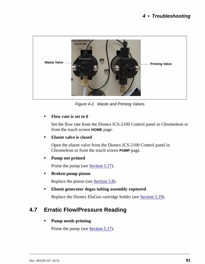
4 • Troubleshooting
Doc. 065291-03 10/12 91
• Flow rate is set to 0
Set the flow rate from the Dionex ICS-2100 Control panel in Chromeleon or from the touch screen HOME page.
• Eluent valve is closed
Open the eluent valve from the Dionex ICS-2100 Control panel in Chromeleon or from the touch screen PUMP page.
• Pump not primed
Prime the pump (see Section 5.17).
• Broken pump piston
Replace the piston (see Section 5.8).
• Eluent generator degas tubing assembly ruptured
Replace the Dionex EluGen cartridge holder (see Section 5.19).
4.7 Erratic Flow/Pressure Reading
• Pump needs priming
Prime the pump (see Section 5.17).
Figure 4-2. Waste and Priming Valves
Waste Valve Priming Valve
Dionex ICS-2100 Ion Chromatography System
92 Doc. 065291-03 10/12
• Damaged piston seal
Replace the piston seal (see Section 5.7).
• Dirty pump check valve
Clean or replace the check valve (see Section 5.6).
• Leaking liquid lines or fittings
Check the liquid lines and fittings for small leaks. Tighten or, if necessary, replace the liquid line connection (see Section 5.3). Refer to Installation of Dionex Liquid Line Fittings (Document No. 031432) for tightening requirements. The manual is included on the Thermo Scientific Reference Library DVD (P/N 053891).
4.8 Excessive System Backpressure
• Restriction in the system plumbing
Check all liquid lines for crimping or blockage. Make sure the ferrule fittings are not overtightened onto tubing. Refer to Installation of Dionex Liquid Line Fittings (Document No. 031432) for details. The manual is included on the Thermo Scientific Reference Library DVD (P/N 053891).
If you have trouble isolating the restriction, refer to Section 5.2.
• Plugged or damaged fitting
Isolate the faulty fitting by loosening fittings, one by one, until the pressure returns to normal. Repair or replace the fitting (see Section 5.3).
• Flow rate through the columns too high
Set the correct rate for your application. If an incorrect flow rate calibration is suspected, calibrate the flow (see Section 5.1.4).
• Clogged column bed supports
Refer to the instructions in the column manual for troubleshooting guidance. Column manuals are included on the Thermo Scientific Reference Library DVD (P/N 053891).
• Contaminated columns
Clean the columns as instructed in the column manual or replace the guard column.
4 • Troubleshooting
Doc. 065291-03 10/12 93
• Plugged injection valve or auxiliary valve passages
Rebuild the valve (see Section 5.4).
4.9 Peak “Ghosting”
“Ghosting” is the appearance of extraneous peaks in a chromatogram. These may be late-eluting peaks from a previous injection. They may also be the result of a contaminated standard or eluent, or a malfunctioning injection valve. These peaks may co-elute with peaks of interest, resulting in nonreproducible peak heights/areas.
• Insufficient time between sample injections
Wait until the previous sample has been completely eluted before making another injection.
• Insufficient flush between samples
Flush the sample loop with at least 10 loop volumes of deionized water or sample between sample injections.
• Incorrect or contaminated standards
Remake standards.
• Incorrect or contaminated eluent
Remake the eluent. Refer to the instructions in the column manual. The manual is included on the Thermo Scientific Reference Library DVD (P/N 053891).
Verify that the correct eluent concentration is selected.
Install or replace the end-line filter on the end of the deionized water line (see Section 3.4.1).
• Malfunctioning injection valve or auxiliary valve
1. Rebuild the valve (see Section 5.4).
2. If the valve leak persists, contact Thermo Fisher Scientific for assistance.
Dionex ICS-2100 Ion Chromatography System
94 Doc. 065291-03 10/12
4.10 Nonreproducible Peak Height or Retention Time
• Column overloading
Dilute the sample (see Section 3.9.3).
• Liquid leaks
Locate and eliminate the leaks (see Section 4.3).
• Incomplete or imprecise filling of the sample loop
1. Fill the sample loop until excess sample exits the waste line.
2. Inspect the 1-cc syringe (P/N 016388) and replace if damaged.
• Pump not primed properly
Prime the pump (see Section 5.17).
4.11 Abnormal Retention Time or Selectivity
• Incorrect eluent
Check the EGC concentration setting.
• Contaminated or degraded sample
Take appropriate precautions when preparing and storing samples to prevent contamination and degradation (see Section 3.9).
• Contaminated column
1. Clean the column as instructed in the column manual. Column manuals are included on the Thermo Scientific Reference Library DVD (P/N 053891).
2. If cleaning is unsuccessful, replace the column.
4.12 No Cell Response
• Cell not properly installed
Verify that the cell front cover is flush against the component panel. If necessary, tighten the two mounting screws. When the cell is correctly
4 • Troubleshooting
Doc. 065291-03 10/12 95
installed and the screws tightened, an electronics connector on the cell plugs into a receptacle inside the Dionex ICS-2100.
• No flow from pump
This condition has several possible causes; see Section 4.5 and Section 4.6 for details.
• Cell electronics malfunctioning
Use the Chromeleon Wellness Panel diagnostics to test the electronics (see Section 5.1 and the Chromeleon Help for instructions). If the variance reading is outside the tolerance range (less than 1 S), the electronics are malfunctioning. Contact Thermo Fisher Scientific for assistance. The Dionex ICS-2100 electronics cannot be serviced by the user.
4.13 High Cell Output
• Background not suppressed by suppressor
Verify that the suppressor is turned on and the current is set to the correct value. Refer to the suppressor manual for additional troubleshooting guidance. Suppressor manuals are included on the Thermo Scientific Reference Library DVD (P/N 053891).
• Sample concentration too high
Dilute the sample (see Section 3.9.3).
• Wrong eluent
Check that you are using the correct eluent for your application.
• Background conductivity not offset from conductivity reading
Before making an injection, allow the background conductivity to equilibrate, and then click Autozero on the Dionex ICS-2100Control panel in Chromeleon or the Dionex ICS-2100 touch screen HOME page.
• Cell out of calibration
Recalibrate the cell (see Section 5.1.3).
Dionex ICS-2100 Ion Chromatography System
96 Doc. 065291-03 10/12
4.14 Baseline Noise or Drift
• Flow system leak; erratic baseline
Check all fittings and liquid lines for leaks. Tighten or, if necessary, replace all liquid line connections. Refer to Installation of Dionex Liquid Line Fittings (Document No. 031432) for tightening requirements. The manual is included on the Thermo Scientific Reference Library DVD (P/N 053891).
• Trapped gases
Release any trapped gases in the cell by loosening the lines to and from the cell and then retightening them. Also loosen and retighten the fittings to and from the suppressor eluent ports.
• Pump not properly primed
Prime the pump (see Section 5.17).
• Incorrect eluent
Check the EGC concentration setting.
• Inadequate system backpressure
Add backpressure tubing between the injection valve and the ELUENT OUT port on the EGC to maintain a pressure of 16 ± 0.7 MPa (2300 ± 100 psi). For details, refer to the Dionex ICS-2100 installation instructions.
• Rapid changes in ambient temperature
Make sure the ambient temperature is between 4 and 40 °C (40 and 104 °F).
Make sure air conditioning and heating vents are directed away from the Dionex ICS-2100 and the Dionex ICS-2100 front door is closed.
• Insufficient system equilibration following changes to operating parameters; especially apparent when operating at high sensitivities
Allow a longer system equilibration time (up to 2 hours) before starting operation.
• Incorrect suppressor operating conditions
Refer to the suppressor manual for troubleshooting information. Suppressor manuals are included on the Thermo Scientific Reference Library DVD (P/N 053891).
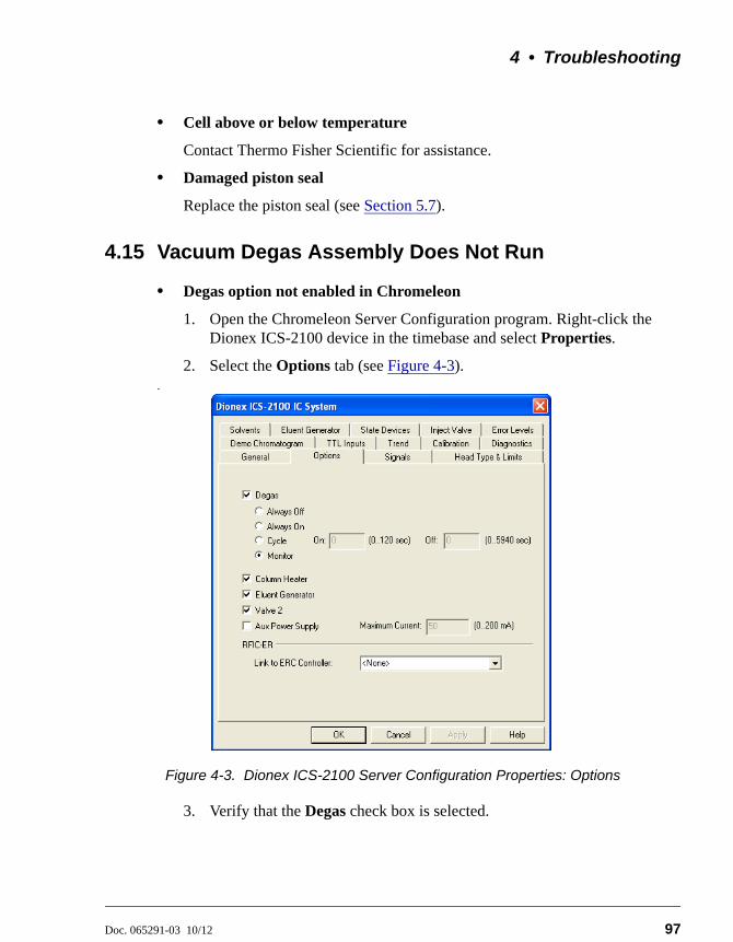
4 • Troubleshooting
Doc. 065291-03 10/12 97
• Cell above or below temperature
Contact Thermo Fisher Scientific for assistance.
• Damaged piston seal
Replace the piston seal (see Section 5.7).
4.15 Vacuum Degas Assembly Does Not Run
• Degas option not enabled in Chromeleon
1. Open the Chromeleon Server Configuration program. Right-click the Dionex ICS-2100 device in the timebase and select Properties.
2. Select the Options tab (see Figure 4-3)..
Figure 4-3. Dionex ICS-2100 Server Configuration Properties: Options
3. Verify that the Degas check box is selected.
Dionex ICS-2100 Ion Chromatography System
98 Doc. 065291-03 10/12
4. Under Degas, verify that the Always Off option is not selected. If it is, select one of the following settings instead:
• Cycle; also select On: 30 seconds and Off: 10 minutes
• Monitor
5. If the Degas settings are correct, but the degas assembly still does not run, test the assembly by selecting the Always On option. The pump should turn on immediately. If it does not, the vacuum degas assembly may need to be replaced. Contact Thermo Fisher Scientific for assistance.
NOTE Degas options can also be selected from the touchscreen PUMP page (see Section B.7).
6. If the degas pump runs when you select Always On, but does not run when Monitor is selected, recalibrate the degas assembly (see Section 5.1.5).
Select the Degas, Always On option only when testing the vacuum degasassembly. Do not select the Always On option for routine use.
Doc. 065291-03 10/12 99
5 • Service
This chapter describes Dionex ICS-2100 service and repair procedures that the user can perform. All procedures not included here, including electronics-related repair procedures, must be performed by Thermo Fisher Scientific personnel. For assistance, contact Technical Support for Dionex products. In the U.S. and Canada, call 1-800-346-6390. Outside the U.S. and Canada, call the nearest Thermo Fisher Scientific office.
Before replacing any part, refer to the troubleshooting information in Chapter 4 to isolate the cause of the problem.
5.1 Diagnostic and Calibration Procedures
Diagnostic and calibration procedures can be performed either from the touch screen or from the Chromeleon Wellness Panel (see Figure 5-1).
For an overview of the Wellness Panel features, see Section 5.1.1. For an overview of the diagnostic and calibration touch screen, see Section 5.1.2. For instructions on performing calibration and diagnostic procedures, see the following sections:
• Calibrating the Conductivity Cell (Section 5.1.3)
• Calibrating the Flow Rate (Section 5.1.4)
• Calibrating the Vacuum Degas Assembly (Section 5.1.5)
Substituting non-Dionex/Thermo Fisher Scientific parts may impairperformance, thereby voiding the product warranty. Refer to thewarranty statement in the Dionex Terms and Conditions for moreinformation.
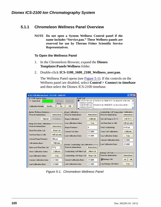
Dionex ICS-2100 Ion Chromatography System
100 Doc. 065291-03 10/12
5.1.1 Chromeleon Wellness Panel Overview
NOTE Do not open a System Wellness Control panel if thename includes “Service.pan.” These Wellness panels arereserved for use by Thermo Fisher Scientific ServiceRepresentatives.
To Open the Wellness Panel
1. In the Chromeleon Browser, expand the Dionex Templates\Panels\Wellness folder.
2. Double-click ICS-1100_1600_2100_Wellness_user.pan.
The Wellness Panel opens (see Figure 5-1). If the controls on the Wellness panel are disabled, select Control > Connect to timebase and then select the Dionex ICS-2100 timebase.
Figure 5-1. Chromeleon Wellness Panel
5 • Service
Doc. 065291-03 10/12 101
Use the Wellness Panel to perform the following functions:
• Calibrate the pump flow rate
• Calibrate the vacuum degas assembly
• Calibrate the conductivity cell
• Test the conductivity cell electronics, using a dummy cell
• Upload calibration values from the Dionex ICS-2100 to the Chromeleon Wellness database
After completing a calibration procedure from the touch screen,always update the Chromeleon Wellness database by clicking theUpload button on the Chromeleon Wellness Panel (see Figure 5-1).This action ensures that the current calibration information is storedin Chromeleon as well as in the Dionex ICS-2100.
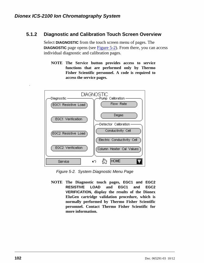
Dionex ICS-2100 Ion Chromatography System
102 Doc. 065291-03 10/12
5.1.2 Diagnostic and Calibration Touch Screen Overview
Select DIAGNOSTIC from the touch screen menu of pages. The DIAGNOSTIC page opens (see Figure 5-2). From there, you can access individual diagnostic and calibration pages.
NOTE The Service button provides access to servicefunctions that are performed only by ThermoFisher Scientific personnel. A code is required toaccess the service pages.
.
NOTE The Diagnostic touch pages, EGC1 and EGC2RESISTIVE LOAD and EGC1 and EGC2VERIFICATION, display the results of the DionexEluGen cartridge validation procedure, which isnormally performed by Thermo Fisher Scientificpersonnel. Contact Thermo Fisher Scientific formore information.
Figure 5-2. System Diagnostic Menu Page
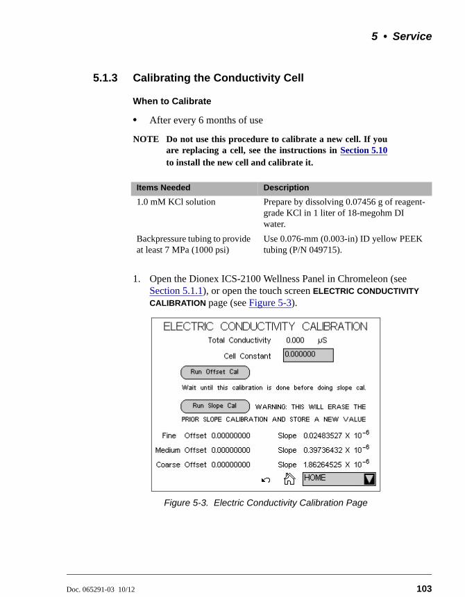
5 • Service
Doc. 065291-03 10/12 103
5.1.3 Calibrating the Conductivity Cell
When to Calibrate
• After every 6 months of use
NOTE Do not use this procedure to calibrate a new cell. If youare replacing a cell, see the instructions in Section 5.10to install the new cell and calibrate it.
1. Open the Dionex ICS-2100 Wellness Panel in Chromeleon (see Section 5.1.1), or open the touch screen ELECTRIC CONDUCTIVITY
CALIBRATION page (see Figure 5-3).
Items Needed Description
1.0 mM KCl solution Prepare by dissolving 0.07456 g of reagent-grade KCl in 1 liter of 18-megohm DI water.
Backpressure tubing to provide at least 7 MPa (1000 psi)
Use 0.076-mm (0.003-in) ID yellow PEEK tubing (P/N 049715).
Figure 5-3. Electric Conductivity Calibration Page
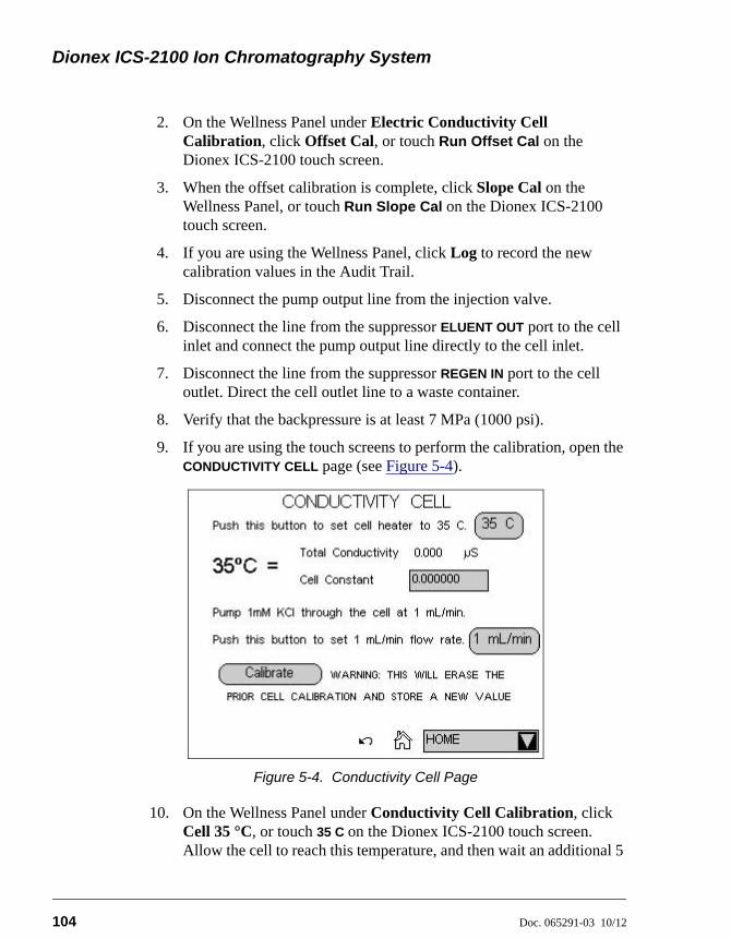
Dionex ICS-2100 Ion Chromatography System
104 Doc. 065291-03 10/12
2. On the Wellness Panel under Electric Conductivity Cell Calibration, click Offset Cal, or touch Run Offset Cal on the Dionex ICS-2100 touch screen.
3. When the offset calibration is complete, click Slope Cal on the Wellness Panel, or touch Run Slope Cal on the Dionex ICS-2100 touch screen.
4. If you are using the Wellness Panel, click Log to record the new calibration values in the Audit Trail.
5. Disconnect the pump output line from the injection valve.
6. Disconnect the line from the suppressor ELUENT OUT port to the cell inlet and connect the pump output line directly to the cell inlet.
7. Disconnect the line from the suppressor REGEN IN port to the cell outlet. Direct the cell outlet line to a waste container.
8. Verify that the backpressure is at least 7 MPa (1000 psi).
9. If you are using the touch screens to perform the calibration, open the CONDUCTIVITY CELL page (see Figure 5-4).
10. On the Wellness Panel under Conductivity Cell Calibration, click Cell 35 °C, or touch 35 C on the Dionex ICS-2100 touch screen. Allow the cell to reach this temperature, and then wait an additional 5
Figure 5-4. Conductivity Cell Page
5 • Service
Doc. 065291-03 10/12 105
minutes to let it stabilize. When the temperature has stabilized, “=” is displayed to the right of the temperature reading on the CONDUCTIVITY CELL page.
11. Select 1.00 mL/min to begin pumping 1.00 mM KCl through the cell at 1.0 mL/min.
12. Wait until the total conductivity reading stabilizes (in about 15 minutes) and then select Calibrate on the Wellness Panel or the touch screen CONDUCTIVITY CELL page.
After calibration, the conductivity reading should be 147.00 ± 2 S and the cell constant should be between 120 and 180. If this is not the case, contact Thermo Fisher Scientific for help.
13. If you are using the Wellness Panel, click Log to record the new calibration values in the Audit Trail.
14. If you are using the touch screen, record the new calibration values in the Chromeleon Wellness database. To do this, open the Wellness Panel (see Section 5.1.1) and click Upload under Update Wellness Database.
15. Flush the KCl solution from the system by pumping deionized water through the cell. When the conductivity drops to less than 1 S/cm, stop the pump.
16. Reconnect the pump to the injection valve and reconnect the line from the suppressor ELUENT OUT port to the cell inlet.
17. Reconnect the cell outlet to the suppressor REGEN IN port.
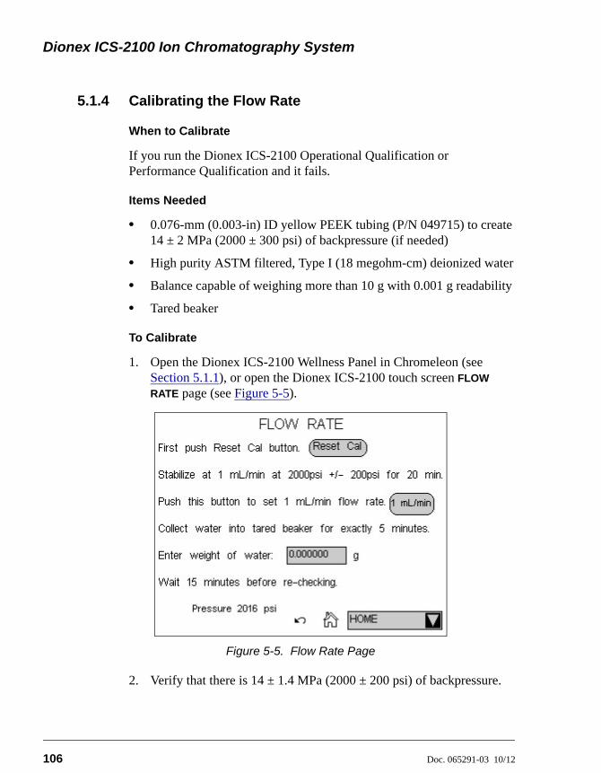
Dionex ICS-2100 Ion Chromatography System
106 Doc. 065291-03 10/12
5.1.4 Calibrating the Flow Rate
When to Calibrate
If you run the Dionex ICS-2100 Operational Qualification or Performance Qualification and it fails.
Items Needed
• 0.076-mm (0.003-in) ID yellow PEEK tubing (P/N 049715) to create 14 ± 2 MPa (2000 ± 300 psi) of backpressure (if needed)
• High purity ASTM filtered, Type I (18 megohm-cm) deionized water
• Balance capable of weighing more than 10 g with 0.001 g readability
• Tared beaker
To Calibrate
1. Open the Dionex ICS-2100 Wellness Panel in Chromeleon (see Section 5.1.1), or open the Dionex ICS-2100 touch screen FLOW
RATE page (see Figure 5-5).
2. Verify that there is 14 ± 1.4 MPa (2000 ± 200 psi) of backpressure.
Figure 5-5. Flow Rate Page
5 • Service
Doc. 065291-03 10/12 107
3. On the Chromeleon Wellness Panel under Pump Flow Rate Calibration, select Reset Cal, or touch Reset Cal on the touch screen.
4. Select 1 mL/min to set the flow rate and begin pumping deionized water.
5. Allow the pump to stabilize for 20 minutes.
6. If you are using the Wellness Panel, click 5.00 min to start the timer. If you are using the touch screen, start an external timer. Immediately start collecting water into the tared beaker.
7. Collect the water for exactly 5.00 minutes.
8. Enter the weight of the water (in grams).
9. If you are using the Wellness Panel, click Calibrate to download the value to the Dionex ICS-2100.
10. To recheck the value, wait at least 15 minutes, and then repeat the calibration.
11. If you are using the Wellness panel, click Log to record the new calibration value in the Audit Trail.
12. If you performed the calibration from the Dionex ICS-2100 touch screen, record the new calibration values in the Chromeleon Wellness database. To do this, open the Wellness Panel (see Section 5.1.1) and click Upload.
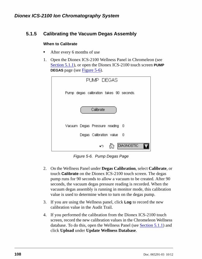
Dionex ICS-2100 Ion Chromatography System
108 Doc. 065291-03 10/12
5.1.5 Calibrating the Vacuum Degas Assembly
When to Calibrate
• After every 6 months of use
1. Open the Dionex ICS-2100 Wellness Panel in Chromeleon (see Section 5.1.1), or open the Dionex ICS-2100 touch screen PUMP
DEGAS page (see Figure 5-6).
2. On the Wellness Panel under Degas Calibration, select Calibrate, or touch Calibrate on the Dionex ICS-2100 touch screen. The degas pump runs for 90 seconds to allow a vacuum to be created. After 90 seconds, the vacuum degas pressure reading is recorded. When the vacuum degas assembly is running in monitor mode, this calibration value is used to determine when to turn on the degas pump.
3. If you are using the Wellness panel, click Log to record the new calibration value in the Audit Trail.
4. If you performed the calibration from the Dionex ICS-2100 touch screen, record the new calibration values in the Chromeleon Wellness database. To do this, open the Wellness Panel (see Section 5.1.1) and click Upload under Update Wellness Database.
Figure 5-6. Pump Degas Page
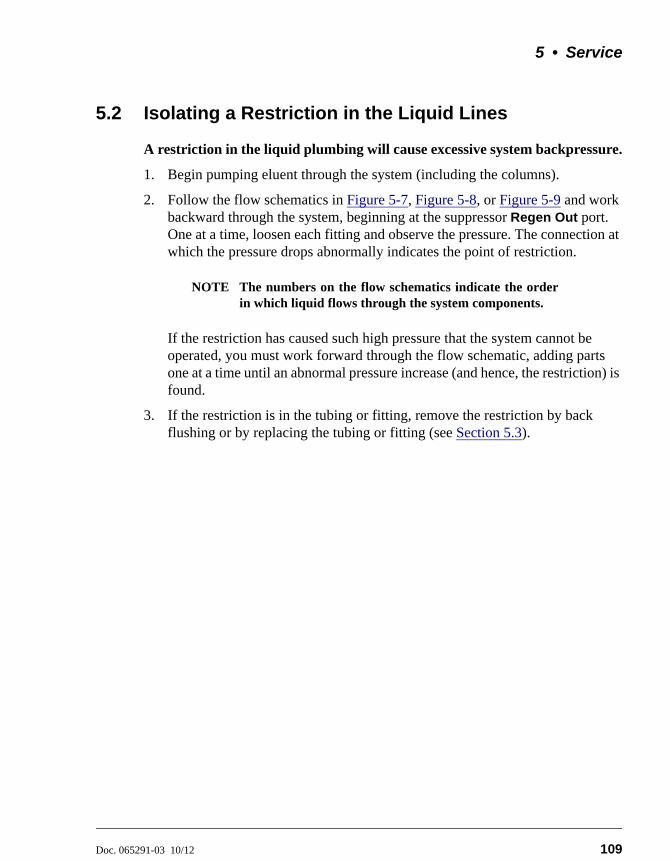
5 • Service
Doc. 065291-03 10/12 109
5.2 Isolating a Restriction in the Liquid Lines
A restriction in the liquid plumbing will cause excessive system backpressure.
1. Begin pumping eluent through the system (including the columns).
2. Follow the flow schematics in Figure 5-7, Figure 5-8, or Figure 5-9 and work backward through the system, beginning at the suppressor Regen Out port. One at a time, loosen each fitting and observe the pressure. The connection at which the pressure drops abnormally indicates the point of restriction.
NOTE The numbers on the flow schematics indicate the orderin which liquid flows through the system components.
If the restriction has caused such high pressure that the system cannot be operated, you must work forward through the flow schematic, adding parts one at a time until an abnormal pressure increase (and hence, the restriction) is found.
3. If the restriction is in the tubing or fitting, remove the restriction by back flushing or by replacing the tubing or fitting (see Section 5.3).
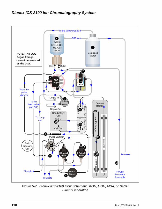
Dionex ICS-2100 Ion Chromatography System
110 Doc. 065291-03 10/12
Figure 5-7. Dionex ICS-2100 Flow Schematic: KOH, LiOH, MSA, or NaOH Eluent Generation
Sample in
To the pump Degas In
Cell In
Cell Out
Column Heater
Suppressor
Heat E
xchanger
To pump inlet
Degas Out
Pulse Damper
EGC Degas
From the pulse
damperDegas In
To waste
Eluent Valve
Pump Head
Pump Head
CR-TC
2
3
5
7
8
12
13
1415
16
17
6
EGC IIKOH, LiOH,
MSA, or NaOH
Inlet Outlet
To Gas Separator Assembly
18
Conductivity Cell
L
L
S
W
P
C10
To the inject valve port P(2)
9
11
Back-pressure
Coil
Valve
EGC Vent
To waste
Deionized Water
1
4
Press.Xducer.
NOTE: The EGC Degas fittings
by the user.cannot be serviced
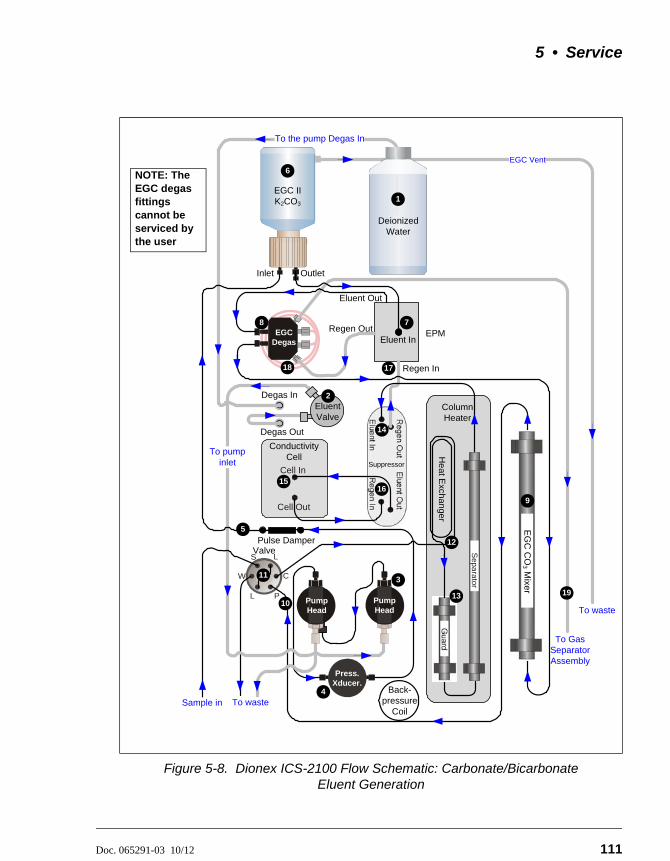
5 • Service
Doc. 065291-03 10/12 111
Figure 5-8. Dionex ICS-2100 Flow Schematic: Carbonate/Bicarbonate Eluent Generation
L
L
S
W
P
C
7EPM
Eluent In
Eluent Out
Regen Out
Regen In17
To the pump Degas In
Cell In
Cell Out
Column Heater
Suppressor
He
at Exchan
ger
To pump inlet
Degas Out
Pulse DamperValve
11
EGC Degas
Degas In
To waste
Sep
ara
tor3
5
8
6
EGC II K2CO3
Inlet Outlet
To Gas Separator Assembly
Conductivity Cell
Sample in
Back-pressure
Coil
10
12
13
14
1516
18
19
EGC Vent
To waste
Deionized Water
1
9
Pump Head
Pump Head
EG
C C
O3 M
ixer
Eluent Valve
2
4
Press.Xducer.
NOTE: The EGC degas fittings cannot be serviced by the user
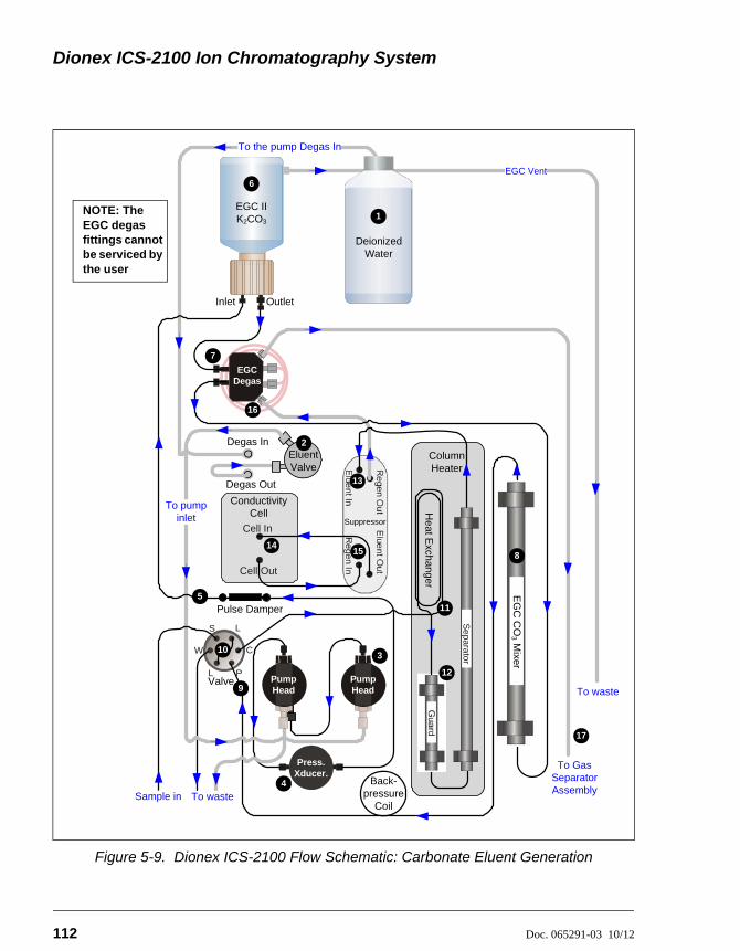
Dionex ICS-2100 Ion Chromatography System
112 Doc. 065291-03 10/12
Figure 5-9. Dionex ICS-2100 Flow Schematic: Carbonate Eluent Generation
L
L
S
W
P
C10
7
17
To the pump Degas In
Cell In
Cell Out
Column Heater
Suppressor
Heat E
xchanger
Pulse Damper
EGC Degas
To waste
Se
parator3
Inlet Outlet
To Gas Separator Assembly
Conductivity Cell
Back-pressure
Coil
Valve
11
12
13
1415
16
EGC Vent
To waste
Deionized Water
1
9
Pump Head
Pump Head
EG
C C
O3 M
ixer
8
4
Press.Xducer.
Degas Out
Degas InEluent Valve
2
To pump inlet
Sample in
5
6
EGC II K2CO3
NOTE: The EGC degas fittings cannot be serviced by the user
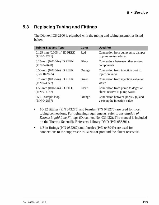
5 • Service
Doc. 065291-03 10/12 113
5.3 Replacing Tubing and Fittings
The Dionex ICS-2100 is plumbed with the tubing and tubing assemblies listed below.
• 10-32 fittings (P/N 043275) and ferrules (P/N 043276) are used for most tubing connections. For tightening requirements, refer to Installation of Dionex Liquid Line Fittings (Document No. 031432). The manual is included on the Thermo Scientific Reference Library DVD (P/N 053891).
• 1/8-in fittings (P/N 052267) and ferrules (P/N 048949) are used for connections to the suppressor REGEN OUT port and the eluent reservoir.
Tubing Size and Type Color Used For
0.125-mm (0.005-in) ID PEEK (P/N 044221)
Red Connection from pump pulse damper to pressure transducer
0.25-mm (0.010-in) ID PEEK (P/N 042690)
Black Connections between other system components
0.50-mm (0.020-in) ID PEEK (P/N 042855)
Orange Connection from injection port to injection valve
0.75-mm (0.030-in) ID PEEK (P/N 044777)
Green Connection from injection valve to waste
1.58-mm (0.062-in) ID PTFE (P/N 014157)
Clear Connection from pump to degas or eluent reservoir; pump waste
25 L sample loop (P/N 042857)
Orange Connection between ports L (1) and L (4) on the injection valve
Dionex ICS-2100 Ion Chromatography System
114 Doc. 065291-03 10/12
5.4 Rebuilding the Injection Valve or Auxiliary Valve
Thermo Fisher Scientific recommends rebuilding the injection valve and the auxiliary valve (if installed) annually. The Injection Valve Rebuild Kit (P/N 057896) contains all required replacement parts for one valve.
NOTE If you prefer, you can replace the auxiliary valve “pod,”instead of rebuilding the valve. Replacing the pod iseasier and faster than rebuilding the auxiliary valve. Forinstructions, see Section 5.5.
1. Turn off the pump from the Dionex ICS-2100 Control panel in Chromeleon or from the touch screen HOME page.
2. Open the Dionex ICS-2100 front door.
3. Disconnect each liquid line connected to the valve.
4. Follow the instructions provided in the Rebuild Kit to replace the rotor seal, isolation seal, and stator face.
5. Reconnect all liquid lines to the injection valve (see Figure 5-10) or auxiliary valve.
6. Close the door.
7. Turn on the pump.
Substituting non-Dionex/Thermo Fisher Scientific parts may impairperformance, thereby voiding the product warranty. Refer to thewarranty statement in the Dionex Terms and Conditions for moreinformation.
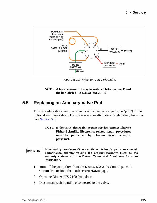
5 • Service
Doc. 065291-03 10/12 115
NOTE A backpressure coil may be installed between port P andthe line labeled TO INJECT VALVE - P.
5.5 Replacing an Auxiliary Valve Pod
This procedure describes how to replace the mechanical part (the “pod”) of the optional auxiliary valve. This procedure is an alternative to rebuilding the valve (see Section 5.4).
NOTE If the valve electronics require service, contact ThermoFisher Scientific. Electronics-related repair proceduresmust be performed by Thermo Fisher Scientificpersonnel.
1. Turn off the pump flow from the Dionex ICS-2100 Control panel in Chromeleonor from the touch screen HOME page.
2. Open the Dionex ICS-2100 front door.
3. Disconnect each liquid line connected to the valve.
Figure 5-10. Injection Valve Plumbing
Substituting non-Dionex/Thermo Fisher Scientific parts may impairperformance, thereby voiding the product warranty. Refer to thewarranty statement in the Dionex Terms and Conditions for moreinformation.
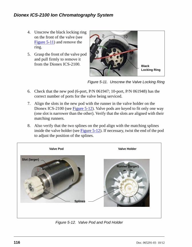
Dionex ICS-2100 Ion Chromatography System
116 Doc. 065291-03 10/12
4. Unscrew the black locking ring on the front of the valve (see Figure 5-11) and remove the ring.
5. Grasp the front of the valve pod and pull firmly to remove it from the Dionex ICS-2100.
Figure 5-11. Unscrew the Valve Locking Ring
6. Check that the new pod (6-port, P/N 061947; 10-port, P/N 061948) has the correct number of ports for the valve being serviced.
7. Align the slots in the new pod with the runner in the valve holder on the Dionex ICS-2100 (see Figure 5-12). Valve pods are keyed to fit only one way (one slot is narrower than the other). Verify that the slots are aligned with their matching runners.
8. Also verify that the two splines on the pod align with the matching splines inside the valve holder (see Figure 5-12). If necessary, twist the end of the pod to adjust the position of the splines.
Figure 5-12. Valve Pod and Pod Holder
Black Locking Ring
Slot (larger)
Splines
Runner (larger)
Valve Pod Valve Holder
5 • Service
Doc. 065291-03 10/12 117
9. Push the pod into the holder until it clicks into place. Replace the black locking ring.
10. Reconnect all liquid lines to the valve.
11. Turn on the pump flow. Check for leaks from the valve. Tighten fittings as required (see Section 5.1.1).
12. Close the door.
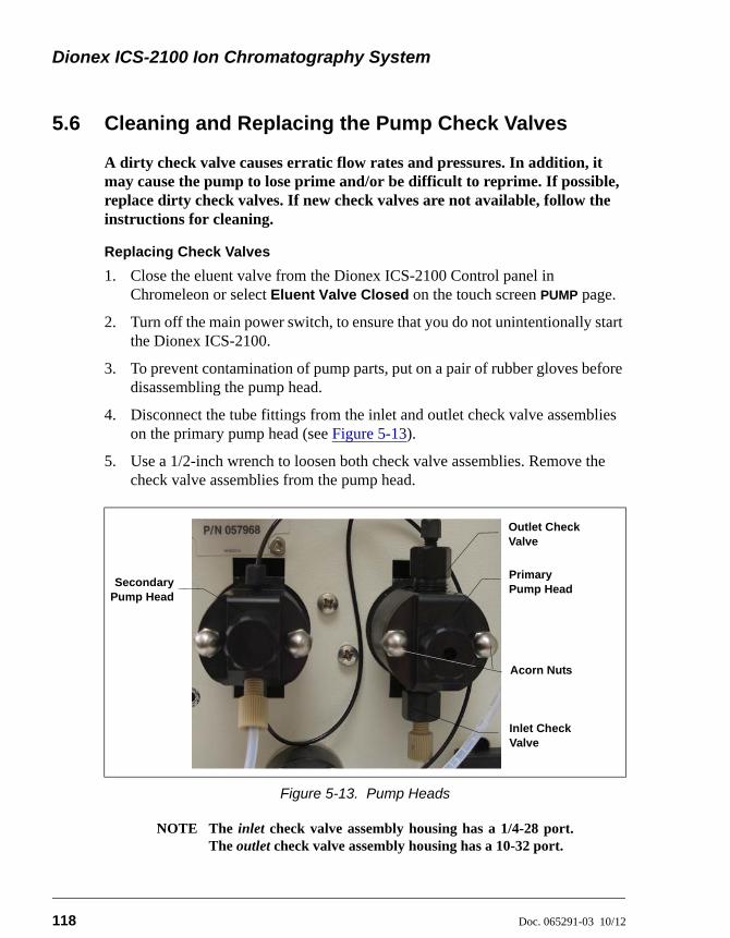
Dionex ICS-2100 Ion Chromatography System
118 Doc. 065291-03 10/12
5.6 Cleaning and Replacing the Pump Check Valves
A dirty check valve causes erratic flow rates and pressures. In addition, it may cause the pump to lose prime and/or be difficult to reprime. If possible, replace dirty check valves. If new check valves are not available, follow the instructions for cleaning.
Replacing Check Valves
1. Close the eluent valve from the Dionex ICS-2100 Control panel in Chromeleon or select Eluent Valve Closed on the touch screen PUMP page.
2. Turn off the main power switch, to ensure that you do not unintentionally start the Dionex ICS-2100.
3. To prevent contamination of pump parts, put on a pair of rubber gloves before disassembling the pump head.
4. Disconnect the tube fittings from the inlet and outlet check valve assemblies on the primary pump head (see Figure 5-13).
5. Use a 1/2-inch wrench to loosen both check valve assemblies. Remove the check valve assemblies from the pump head.
NOTE The inlet check valve assembly housing has a 1/4-28 port.The outlet check valve assembly housing has a 10-32 port.
Figure 5-13. Pump Heads
SecondaryPump Head
Primary Pump Head
Outlet Check Valve
Inlet Check Valve
Acorn Nuts
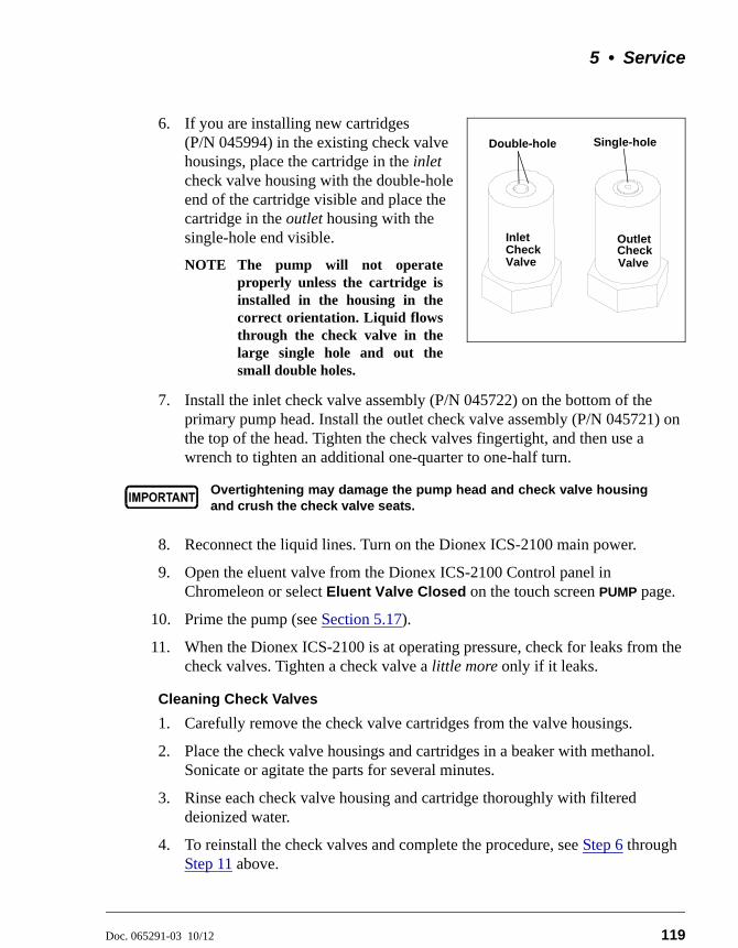
5 • Service
Doc. 065291-03 10/12 119
6. If you are installing new cartridges (P/N 045994) in the existing check valve housings, place the cartridge in the inlet check valve housing with the double-hole end of the cartridge visible and place the cartridge in the outlet housing with the single-hole end visible.
NOTE The pump will not operateproperly unless the cartridge isinstalled in the housing in thecorrect orientation. Liquid flowsthrough the check valve in thelarge single hole and out thesmall double holes.
7. Install the inlet check valve assembly (P/N 045722) on the bottom of the primary pump head. Install the outlet check valve assembly (P/N 045721) on the top of the head. Tighten the check valves fingertight, and then use a wrench to tighten an additional one-quarter to one-half turn.
8. Reconnect the liquid lines. Turn on the Dionex ICS-2100 main power.
9. Open the eluent valve from the Dionex ICS-2100 Control panel in Chromeleon or select Eluent Valve Closed on the touch screen PUMP page.
10. Prime the pump (see Section 5.17).
11. When the Dionex ICS-2100 is at operating pressure, check for leaks from the check valves. Tighten a check valve a little more only if it leaks.
Cleaning Check Valves
1. Carefully remove the check valve cartridges from the valve housings.
2. Place the check valve housings and cartridges in a beaker with methanol. Sonicate or agitate the parts for several minutes.
3. Rinse each check valve housing and cartridge thoroughly with filtered deionized water.
4. To reinstall the check valves and complete the procedure, see Step 6 through Step 11 above.
Overtightening may damage the pump head and check valve housingand crush the check valve seats.
InletCheck Valve
CheckOutlet
Valve
Double-hole Single-hole
Dionex ICS-2100 Ion Chromatography System
120 Doc. 065291-03 10/12
5.7 Replacing a Pump Piston Seal and Piston Rinse Seal
A damaged seal allows leakage past the piston, as well as leakage from the piston seal wash housing. The pump may be difficult to prime, flow rates may be unstable, and there may be baseline noise.
Preparation
1. Rinse the pump flow path with deionized water. Direct the flow to waste by opening the waste valve on the secondary pump head (see Figure 5-16). To open the valve, turn the knob one-quarter to one-half turn counterclockwise.
2. After rinsing, close the waste valve.
3. Close the eluent valve from the Dionex ICS-2100 Control panel in Chromeleon or select Eluent Valve Closed on the touch screen PUMP page.
4. To prevent contamination of pump parts, put on a pair of rubber gloves before disassembling the pump head.
Removing the Head and Piston
1. Turn off the main power switch, to ensure that you do not unintentionally start the Dionex ICS-2100.
2. Disconnect all tubing connections to the pump head.
3. Locate the open-end wrench (P/N 014605) provided in the Dionex ICS-2100 Ship Kit (P/N 064375). Use the wrench to remove the two acorn nuts (see Figure 5-13) from the pump head.
4. Slowly pull the head and allow it to separate from the housing. Carefully disengage the head from the piston by pulling the head straight off and away from its mounting studs.
Lateral motion while disengaging the pump head from the piston maybreak the piston.
Un mouvement latéral pendant la séparation de la tête et du pistonpeut casser le piston.
Vermeiden Sie Seitwärtsbewegungen, wenn Sie den Kopf vom Kolbenlösen. Andernfalls kann der Kolben brechen.
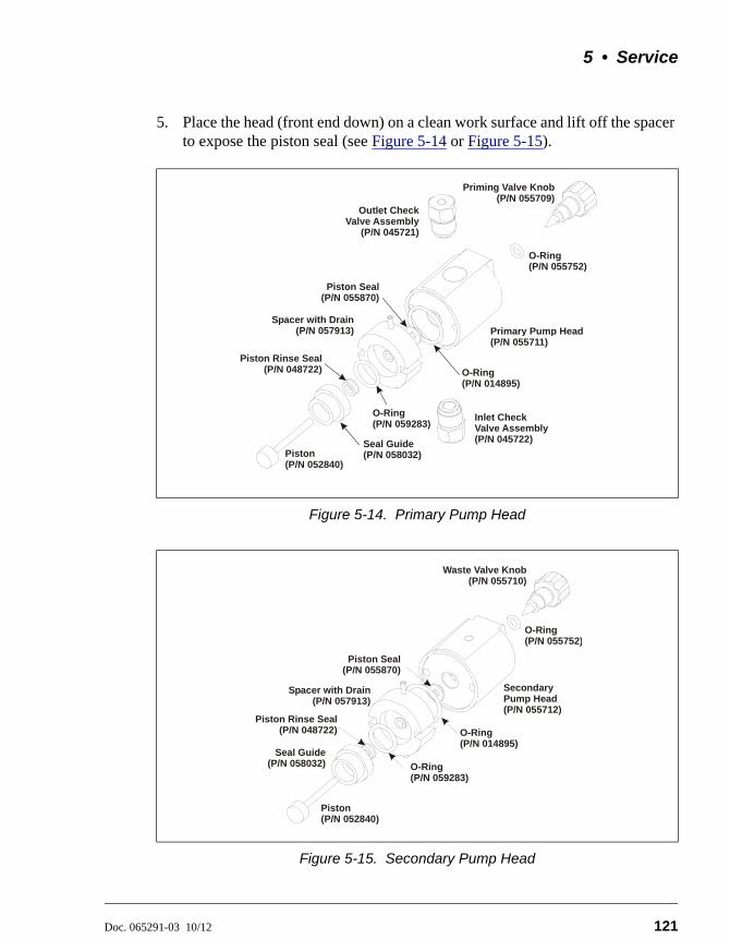
5 • Service
Doc. 065291-03 10/12 121
5. Place the head (front end down) on a clean work surface and lift off the spacer to expose the piston seal (see Figure 5-14 or Figure 5-15).
Figure 5-14. Primary Pump Head
Figure 5-15. Secondary Pump Head
Piston(P/N 052840)
O-Ring(P/N 055752)
Piston Seal(P/N 055870)
Primary Pump Head(P/N 055711)
Seal Guide(P/N 058032)
Spacer with Drain(P/N 057913)
Priming Valve Knob(P/N 055709)
Inlet Check Valve Assembly(P/N 045722)
Outlet Check Valve Assembly
(P/N 045721)
O-Ring(P/N 059283)
Piston Rinse Seal(P/N 048722) O-Ring
(P/N 014895)
Piston(P/N 052840)
Seal Guide(P/N 058032)
O-Ring(P/N 055752)
Piston Seal(P/N 055870)
Secondary Pump Head(P/N 055712)
Spacer with Drain(P/N 057913)
Waste Valve Knob(P/N 055710)
O-Ring(P/N 059283)
Piston Rinse Seal(P/N 048722) O-Ring
(P/N 014895)
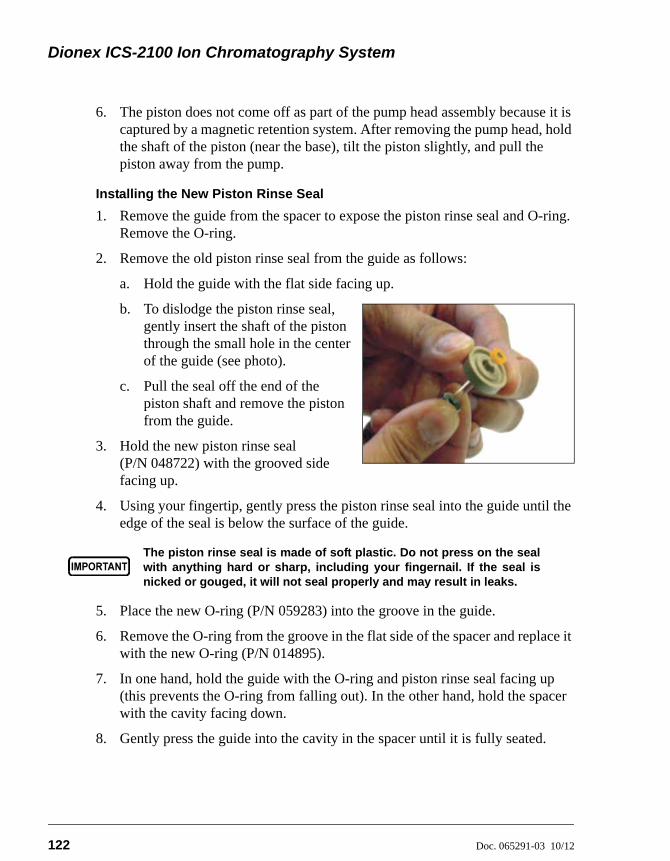
Dionex ICS-2100 Ion Chromatography System
122 Doc. 065291-03 10/12
6. The piston does not come off as part of the pump head assembly because it is captured by a magnetic retention system. After removing the pump head, hold the shaft of the piston (near the base), tilt the piston slightly, and pull the piston away from the pump.
Installing the New Piston Rinse Seal
1. Remove the guide from the spacer to expose the piston rinse seal and O-ring. Remove the O-ring.
2. Remove the old piston rinse seal from the guide as follows:
a. Hold the guide with the flat side facing up.
b. To dislodge the piston rinse seal, gently insert the shaft of the piston through the small hole in the center of the guide (see photo).
c. Pull the seal off the end of the piston shaft and remove the piston from the guide.
3. Hold the new piston rinse seal (P/N 048722) with the grooved side facing up.
4. Using your fingertip, gently press the piston rinse seal into the guide until the edge of the seal is below the surface of the guide.
5. Place the new O-ring (P/N 059283) into the groove in the guide.
6. Remove the O-ring from the groove in the flat side of the spacer and replace it with the new O-ring (P/N 014895).
7. In one hand, hold the guide with the O-ring and piston rinse seal facing up (this prevents the O-ring from falling out). In the other hand, hold the spacer with the cavity facing down.
8. Gently press the guide into the cavity in the spacer until it is fully seated.
The piston rinse seal is made of soft plastic. Do not press on the sealwith anything hard or sharp, including your fingernail. If the seal isnicked or gouged, it will not seal properly and may result in leaks.
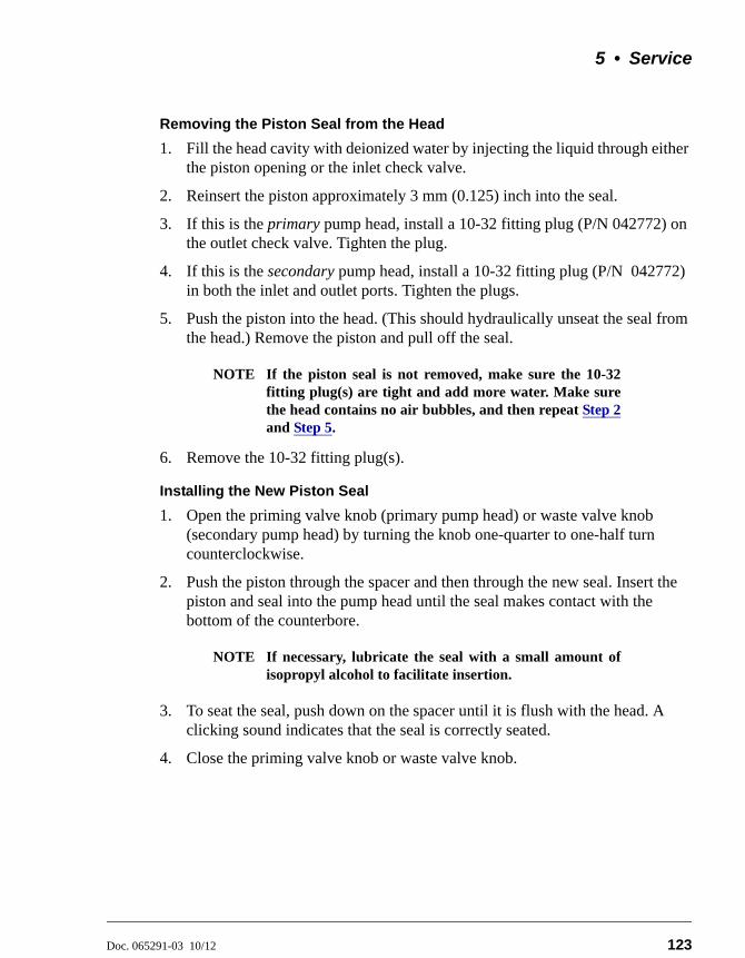
5 • Service
Doc. 065291-03 10/12 123
Removing the Piston Seal from the Head
1. Fill the head cavity with deionized water by injecting the liquid through either the piston opening or the inlet check valve.
2. Reinsert the piston approximately 3 mm (0.125) inch into the seal.
3. If this is the primary pump head, install a 10-32 fitting plug (P/N 042772) on the outlet check valve. Tighten the plug.
4. If this is the secondary pump head, install a 10-32 fitting plug (P/N 042772) in both the inlet and outlet ports. Tighten the plugs.
5. Push the piston into the head. (This should hydraulically unseat the seal from the head.) Remove the piston and pull off the seal.
NOTE If the piston seal is not removed, make sure the 10-32fitting plug(s) are tight and add more water. Make surethe head contains no air bubbles, and then repeat Step 2and Step 5.
6. Remove the 10-32 fitting plug(s).
Installing the New Piston Seal
1. Open the priming valve knob (primary pump head) or waste valve knob (secondary pump head) by turning the knob one-quarter to one-half turn counterclockwise.
2. Push the piston through the spacer and then through the new seal. Insert the piston and seal into the pump head until the seal makes contact with the bottom of the counterbore.
NOTE If necessary, lubricate the seal with a small amount ofisopropyl alcohol to facilitate insertion.
3. To seat the seal, push down on the spacer until it is flush with the head. A clicking sound indicates that the seal is correctly seated.
4. Close the priming valve knob or waste valve knob.
Dionex ICS-2100 Ion Chromatography System
124 Doc. 065291-03 10/12
Reinstalling the Head and Piston
Thermo Fisher Scientific recommends reinstalling the head and piston as a single assembly, so that the piston centers itself onto the magnetic follower.
1. Hold the assembled spacer and guide with the drain tubes aligned vertically and press the spacer into the head until it is flush with the indented surface of the head.
2. Insert the piston so that 1/4 inch of the shaft is exposed. This ensures that the magnet in the follower picks up the piston. (The follower is the cylinder that holds the piston in place as it moves in and out of the pump head assembly.)
3. Reinstall the head and piston assembly; use a wrench to tighten the nuts evenly (12 in-lb torque).
Completing the Procedure
1. Reconnect all liquid lines to the pump head.
2. Turn on the main power switch.
3. Open the eluent valve.
4. Prime the pump (see Section 5.17).
5.8 Replacing a Pump Piston
Continued leaking of the piston seal after installation of a new seal (assuming the pump head is tight) indicates a dirty, scratched, or broken piston.
Follow the instructions in Section 5.7 to install a new piston (P/N 052840) and piston seal (P/N 055870).
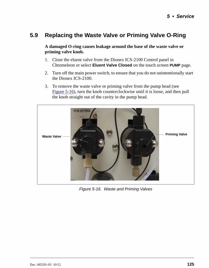
5 • Service
Doc. 065291-03 10/12 125
5.9 Replacing the Waste Valve or Priming Valve O-Ring
A damaged O-ring causes leakage around the base of the waste valve or priming valve knob.
1. Close the eluent valve from the Dionex ICS-2100 Control panel in Chromeleon or select Eluent Valve Closed on the touch screen PUMP page.
2. Turn off the main power switch, to ensure that you do not unintentionally start the Dionex ICS-2100.
3. To remove the waste valve or priming valve from the pump head (see Figure 5-16), turn the knob counterclockwise until it is loose, and then pull the knob straight out of the cavity in the pump head.
Figure 5-16. Waste and Priming Valves
Waste ValvePriming Valve
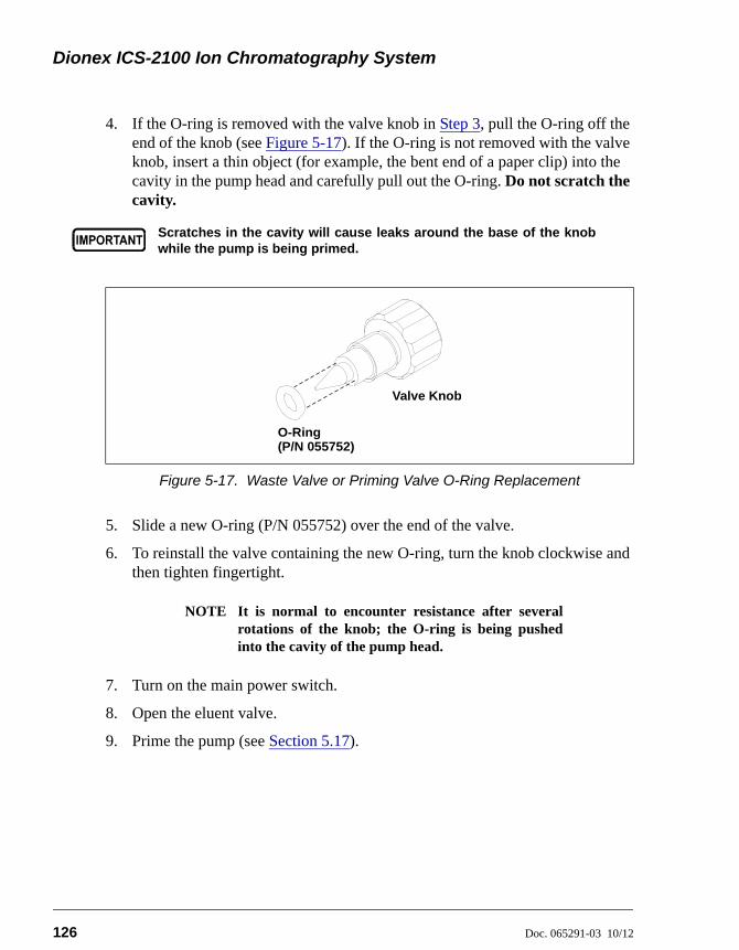
Dionex ICS-2100 Ion Chromatography System
126 Doc. 065291-03 10/12
4. If the O-ring is removed with the valve knob in Step 3, pull the O-ring off the end of the knob (see Figure 5-17). If the O-ring is not removed with the valve knob, insert a thin object (for example, the bent end of a paper clip) into the cavity in the pump head and carefully pull out the O-ring. Do not scratch the cavity.
5. Slide a new O-ring (P/N 055752) over the end of the valve.
6. To reinstall the valve containing the new O-ring, turn the knob clockwise and then tighten fingertight.
NOTE It is normal to encounter resistance after severalrotations of the knob; the O-ring is being pushedinto the cavity of the pump head.
7. Turn on the main power switch.
8. Open the eluent valve.
9. Prime the pump (see Section 5.17).
Scratches in the cavity will cause leaks around the base of the knobwhile the pump is being primed.
Figure 5-17. Waste Valve or Priming Valve O-Ring Replacement
Valve Knob
O-Ring(P/N 055752)
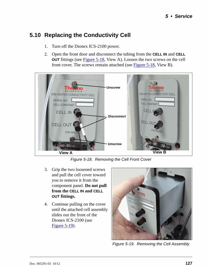
5 • Service
Doc. 065291-03 10/12 127
5.10 Replacing the Conductivity Cell
1. Turn off the Dionex ICS-2100 power.
2. Open the front door and disconnect the tubing from the CELL IN and CELL
OUT fittings (see Figure 5-18, View A). Loosen the two screws on the cell front cover. The screws remain attached (see Figure 5-18, View B).
Figure 5-18. Removing the Cell Front Cover
3. Grip the two loosened screws and pull the cell cover toward you to remove it from the component panel. Do not pull from the CELL IN and CELL
OUT fittings.
4. Continue pulling on the cover until the attached cell assembly slides out the front of the Dionex ICS-2100 (see Figure 5-19).
Figure 5-19. Removing the Cell Assembly
Disconnect
Unscrew
Unscrew
View A View B
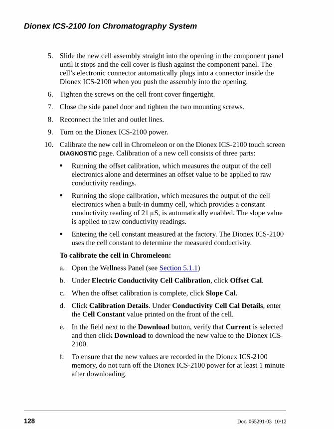
Dionex ICS-2100 Ion Chromatography System
128 Doc. 065291-03 10/12
5. Slide the new cell assembly straight into the opening in the component panel until it stops and the cell cover is flush against the component panel. The cell’s electronic connector automatically plugs into a connector inside the Dionex ICS-2100 when you push the assembly into the opening.
6. Tighten the screws on the cell front cover fingertight.
7. Close the side panel door and tighten the two mounting screws.
8. Reconnect the inlet and outlet lines.
9. Turn on the Dionex ICS-2100 power.
10. Calibrate the new cell in Chromeleon or on the Dionex ICS-2100 touch screen DIAGNOSTIC page. Calibration of a new cell consists of three parts:
• Running the offset calibration, which measures the output of the cell electronics alone and determines an offset value to be applied to raw conductivity readings.
• Running the slope calibration, which measures the output of the cell electronics when a built-in dummy cell, which provides a constant conductivity reading of 21 S, is automatically enabled. The slope value is applied to raw conductivity readings.
• Entering the cell constant measured at the factory. The Dionex ICS-2100 uses the cell constant to determine the measured conductivity.
To calibrate the cell in Chromeleon:
a. Open the Wellness Panel (see Section 5.1.1)
b. Under Electric Conductivity Cell Calibration, click Offset Cal.
c. When the offset calibration is complete, click Slope Cal.
d. Click Calibration Details. Under Conductivity Cell Cal Details, enter the Cell Constant value printed on the front of the cell.
e. In the field next to the Download button, verify that Current is selected and then click Download to download the new value to the Dionex ICS-2100.
f. To ensure that the new values are recorded in the Dionex ICS-2100 memory, do not turn off the Dionex ICS-2100 power for at least 1 minute after downloading.
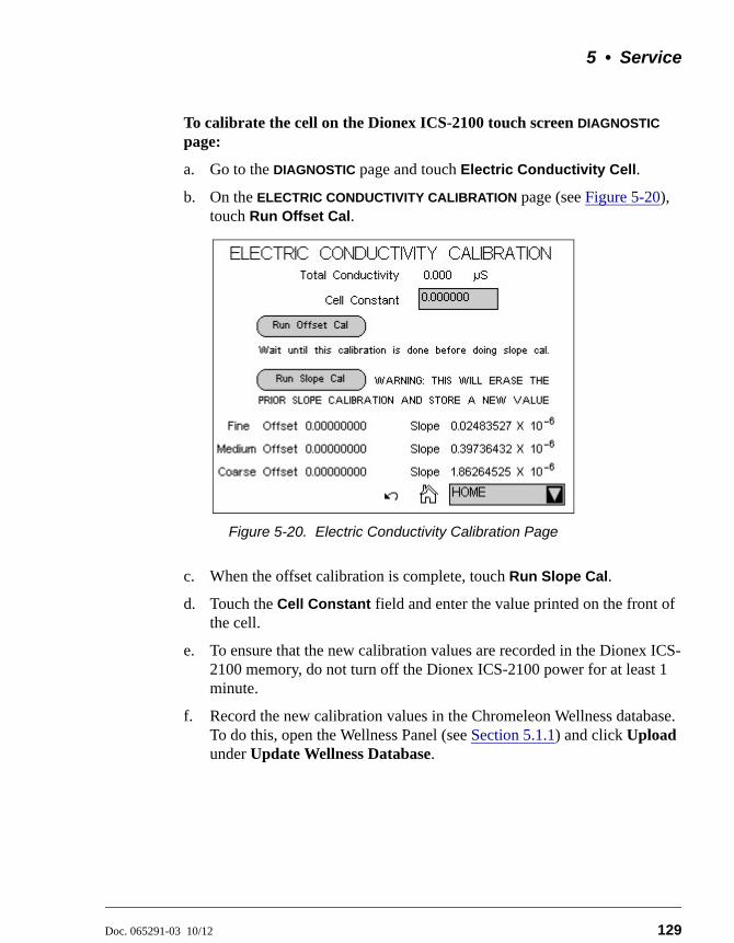
5 • Service
Doc. 065291-03 10/12 129
To calibrate the cell on the Dionex ICS-2100 touch screen DIAGNOSTIC page:
a. Go to the DIAGNOSTIC page and touch Electric Conductivity Cell.
b. On the ELECTRIC CONDUCTIVITY CALIBRATION page (see Figure 5-20), touch Run Offset Cal.
c. When the offset calibration is complete, touch Run Slope Cal.
d. Touch the Cell Constant field and enter the value printed on the front of the cell.
e. To ensure that the new calibration values are recorded in the Dionex ICS-2100 memory, do not turn off the Dionex ICS-2100 power for at least 1 minute.
f. Record the new calibration values in the Chromeleon Wellness database. To do this, open the Wellness Panel (see Section 5.1.1) and click Upload under Update Wellness Database.
Figure 5-20. Electric Conductivity Calibration Page
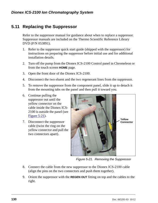
Dionex ICS-2100 Ion Chromatography System
130 Doc. 065291-03 10/12
5.11 Replacing the Suppressor
Refer to the suppressor manual for guidance about when to replace a suppressor. Suppressor manuals are included on the Thermo Scientific Reference Library DVD (P/N 053891).
1. Refer to the suppressor quick start guide (shipped with the suppressor) for instructions on preparing the suppressor before initial use and for additional installation details.
2. Turn off the pump from the Dionex ICS-2100 Control panel in Chromeleon or from the touch screen HOME page.
3. Open the front door of the Dionex ICS-2100.
4. Disconnect the two eluent and the two regenerant lines from the suppressor.
5. To remove the suppressor from the component panel, slide it up to detach it from the mounting tabs on the panel and then pull it toward you.
6. Continue pulling the suppressor out until the yellow connector on the cable inside the Dionex ICS-2100 is outside the panel (see Figure 5-21).
7. Disconnect the suppressor cable (twist the ring on the yellow connector and pull the two connectors apart).
Figure 5-21. Removing the Suppressor
8. Connect the cable from the new suppressor to the Dionex ICS-2100 cable (align the pins on the two connectors and push them together).
9. Orient the suppressor with the REGEN OUT fitting on top and the cables to the right.
YellowConnector
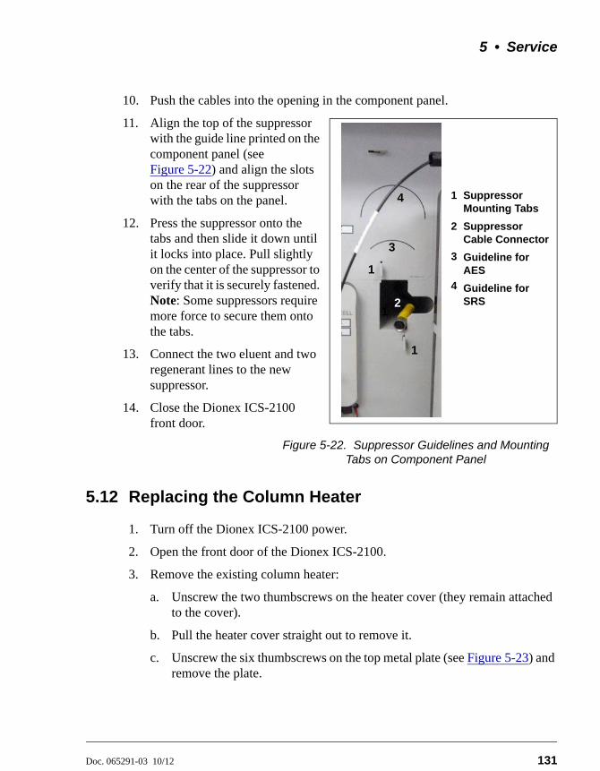
5 • Service
Doc. 065291-03 10/12 131
10. Push the cables into the opening in the component panel.
11. Align the top of the suppressor with the guide line printed on the component panel (see Figure 5-22) and align the slots on the rear of the suppressor with the tabs on the panel.
12. Press the suppressor onto the tabs and then slide it down until it locks into place. Pull slightly on the center of the suppressor to verify that it is securely fastened. Note: Some suppressors require more force to secure them onto the tabs.
13. Connect the two eluent and two regenerant lines to the new suppressor.
14. Close the Dionex ICS-2100 front door.
Figure 5-22. Suppressor Guidelines and Mounting Tabs on Component Panel
5.12 Replacing the Column Heater
1. Turn off the Dionex ICS-2100 power.
2. Open the front door of the Dionex ICS-2100.
3. Remove the existing column heater:
a. Unscrew the two thumbscrews on the heater cover (they remain attached to the cover).
b. Pull the heater cover straight out to remove it.
c. Unscrew the six thumbscrews on the top metal plate (see Figure 5-23) and remove the plate.
1
12
3
4
1
Suppressor Mounting Tabs
Suppressor Cable Connector
Guideline for AES
Guideline for SRS
1
2
3
4
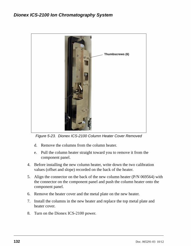
Dionex ICS-2100 Ion Chromatography System
132 Doc. 065291-03 10/12
Figure 5-23. Dionex ICS-2100 Column Heater Cover Removed
d. Remove the columns from the column heater.
e. Pull the column heater straight toward you to remove it from the component panel.
4. Before installing the new column heater, write down the two calibration values (offset and slope) recorded on the back of the heater.
5. Align the connector on the back of the new column heater (P/N 069564) with the connector on the component panel and push the column heater onto the component panel.
6. Remove the heater cover and the metal plate on the new heater.
7. Install the columns in the new heater and replace the top metal plate and heater cover.
8. Turn on the Dionex ICS-2100 power.
Thumbscrews (6)
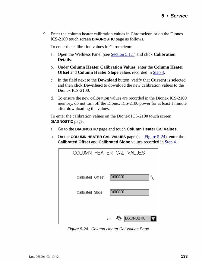
5 • Service
Doc. 065291-03 10/12 133
9. Enter the column heater calibration values in Chromeleon or on the Dionex ICS-2100 touch screen DIAGNOSTIC page as follows.
To enter the calibration values in Chromeleon:
a. Open the Wellness Panel (see Section 5.1.1) and click Calibration Details.
b. Under Column Heater Calibration Values, enter the Column Heater Offset and Column Heater Slope values recorded in Step 4.
c. In the field next to the Download button, verify that Current is selected and then click Download to download the new calibration values to the Dionex ICS-2100.
d. To ensure the new calibration values are recorded in the Dionex ICS-2100 memory, do not turn off the Dionex ICS-2100 power for at least 1 minute after downloading the values.
To enter the calibration values on the Dionex ICS-2100 touch screen DIAGNOSTIC page:
a. Go to the DIAGNOSTIC page and touch Column Heater Cal Values.
b. On the COLUMN HEATER CAL VALUES page (see Figure 5-24), enter the Calibrated Offset and Calibrated Slope values recorded in Step 4.
Figure 5-24. Column Heater Cal Values Page
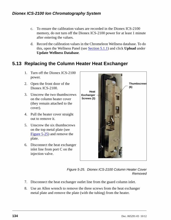
Dionex ICS-2100 Ion Chromatography System
134 Doc. 065291-03 10/12
c. To ensure the calibration values are recorded in the Dionex ICS-2100 memory, do not turn off the Dionex ICS-2100 power for at least 1 minute after entering the values.
d. Record the calibration values in the Chromeleon Wellness database. To do this, open the Wellness Panel (see Section 5.1.1) and click Upload under Update Wellness Database.
5.13 Replacing the Column Heater Heat Exchanger
1. Turn off the Dionex ICS-2100 power.
2. Open the front door of the Dionex ICS-2100.
3. Unscrew the two thumbscrews on the column heater cover (they remain attached to the cover).
4. Pull the heater cover straight out to remove it.
5. Unscrew the six thumbscrews on the top metal plate (see Figure 5-25) and remove the plate.
6. Disconnect the heat exchanger inlet line from port C on the injection valve.
Figure 5-25. Dionex ICS-2100 Column Heater CoverRemoved
7. Disconnect the heat exchanger outlet line from the guard column inlet.
8. Use an Allen wrench to remove the three screws from the heat exchanger metal plate and remove the plate (with the tubing) from the heater.
HeatExchangerScrews (3)
Thumbscrews(6)
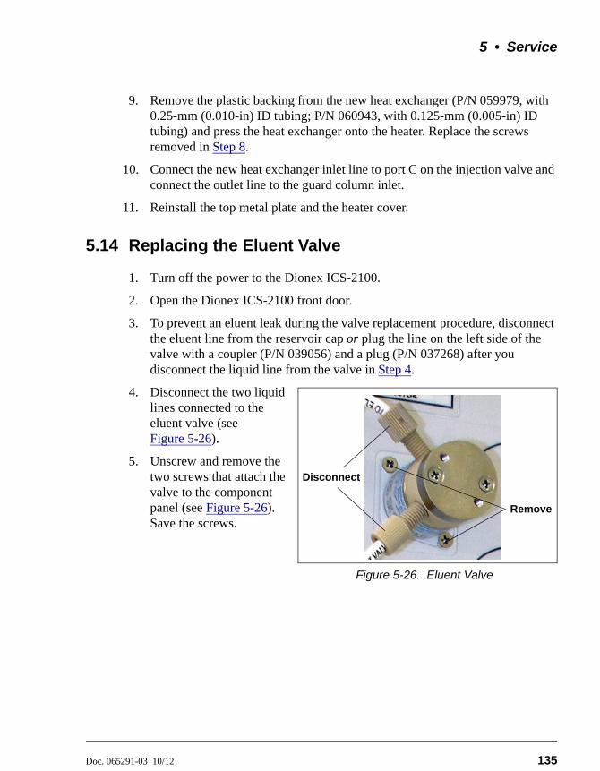
5 • Service
Doc. 065291-03 10/12 135
9. Remove the plastic backing from the new heat exchanger (P/N 059979, with 0.25-mm (0.010-in) ID tubing; P/N 060943, with 0.125-mm (0.005-in) ID tubing) and press the heat exchanger onto the heater. Replace the screws removed in Step 8.
10. Connect the new heat exchanger inlet line to port C on the injection valve and connect the outlet line to the guard column inlet.
11. Reinstall the top metal plate and the heater cover.
5.14 Replacing the Eluent Valve
1. Turn off the power to the Dionex ICS-2100.
2. Open the Dionex ICS-2100 front door.
3. To prevent an eluent leak during the valve replacement procedure, disconnect the eluent line from the reservoir cap or plug the line on the left side of the valve with a coupler (P/N 039056) and a plug (P/N 037268) after you disconnect the liquid line from the valve in Step 4.
4. Disconnect the two liquid lines connected to the eluent valve (see Figure 5-26).
5. Unscrew and remove the two screws that attach the valve to the component panel (see Figure 5-26). Save the screws.
Figure 5-26. Eluent Valve
Remove
Disconnect
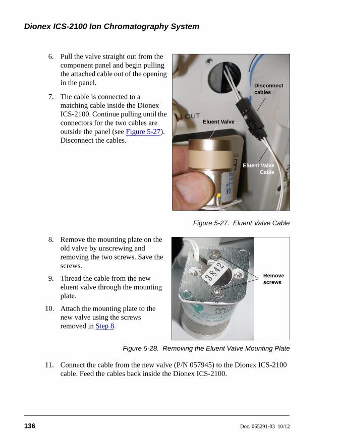
Dionex ICS-2100 Ion Chromatography System
136 Doc. 065291-03 10/12
6. Pull the valve straight out from the component panel and begin pulling the attached cable out of the opening in the panel.
7. The cable is connected to a matching cable inside the Dionex ICS-2100. Continue pulling until the connectors for the two cables are outside the panel (see Figure 5-27). Disconnect the cables.
Figure 5-27. Eluent Valve Cable
8. Remove the mounting plate on the old valve by unscrewing and removing the two screws. Save the screws.
9. Thread the cable from the new eluent valve through the mounting plate.
10. Attach the mounting plate to the new valve using the screws removed in Step 8.
Figure 5-28. Removing the Eluent Valve Mounting Plate
11. Connect the cable from the new valve (P/N 057945) to the Dionex ICS-2100 cable. Feed the cables back inside the Dionex ICS-2100.
Eluent ValveCable
Disconnect cables
Eluent Valve
Remove screws
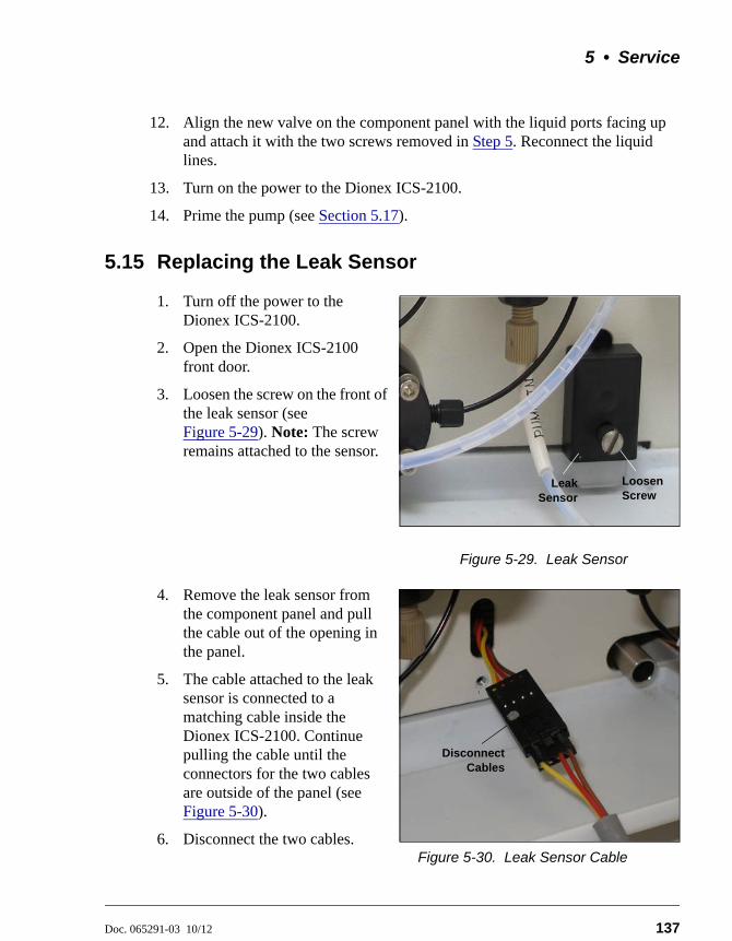
5 • Service
Doc. 065291-03 10/12 137
12. Align the new valve on the component panel with the liquid ports facing up and attach it with the two screws removed in Step 5. Reconnect the liquid lines.
13. Turn on the power to the Dionex ICS-2100.
14. Prime the pump (see Section 5.17).
5.15 Replacing the Leak Sensor
1. Turn off the power to the Dionex ICS-2100.
2. Open the Dionex ICS-2100 front door.
3. Loosen the screw on the front of the leak sensor (see Figure 5-29). Note: The screw remains attached to the sensor.
Figure 5-29. Leak Sensor
4. Remove the leak sensor from the component panel and pull the cable out of the opening in the panel.
5. The cable attached to the leak sensor is connected to a matching cable inside the Dionex ICS-2100. Continue pulling the cable until the connectors for the two cables are outside of the panel (see Figure 5-30).
6. Disconnect the two cables.Figure 5-30. Leak Sensor Cable
LeakSensor
LoosenScrew
DisconnectCables

Dionex ICS-2100 Ion Chromatography System
138 Doc. 065291-03 10/12
7. Connect the cable from the new leak sensor (P/N 058053) to the Dionex ICS-2100 cable.
8. Feed the cables back inside the Dionex ICS-2100. Align the leak sensor with the component panel opening and fingertighten the screw.
9. Make sure the leak sensor does not touch the bottom of the drip tray.
5.16 Priming the Pump
1. Verify that the eluent reservoir is filled, the reservoir cap is installed and hand tightened, and the liquid line from the Dionex ICS-2100 to the reservoir cap is connected.
2. Verify that the waste lines are directed to a waste container.
3. The priming procedure consists of two parts:
• Priming the eluent lines with a syringe (see Section 5.16.1). Perform this procedure at initial installation, after changing eluents, or when eluent lines are empty.
• Priming the pump heads with the Prime button (see Section 5.16.2). Perform this procedure after the eluent lines are primed.
5.16.1 Priming the Eluent Lines with a Syringe
NOTE Prime the eluent lines after initial installation, afterchanging eluents, or when eluent lines are empty.
1. Verify that the pump is turned off.
2. Connect a 10 mL syringe (P/N 079803) to the priming valve port on the primary pump head (see Figure 5-31).
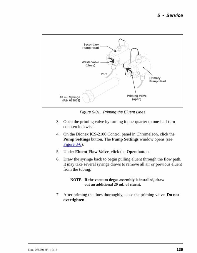
5 • Service
Doc. 065291-03 10/12 139
3. Open the priming valve by turning it one-quarter to one-half turn counterclockwise.
4. On the Dionex ICS-2100 Control panel in Chromeleon, click the Pump Settings button. The Pump Settings window opens (see Figure 3-6).
5. Under Eluent Flow Valve, click the Open button.
6. Draw the syringe back to begin pulling eluent through the flow path. It may take several syringe draws to remove all air or previous eluent from the tubing.
NOTE If the vacuum degas assembly is installed, drawout an additional 20 mL of eluent.
7. After priming the lines thoroughly, close the priming valve. Do not overtighten.
Figure 5-31. Priming the Eluent Lines
10 mL Syringe(P/N 079803)
Priming Valve (open)
Port
Waste Valve(close)
PrimaryPump Head
SecondaryPump Head
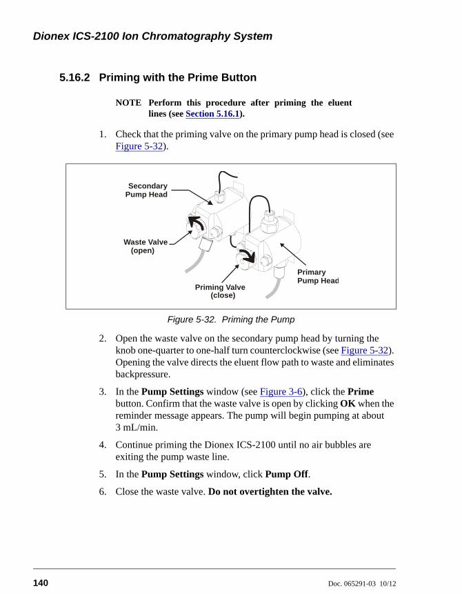
Dionex ICS-2100 Ion Chromatography System
140 Doc. 065291-03 10/12
5.16.2 Priming with the Prime Button
NOTE Perform this procedure after priming the eluentlines (see Section 5.16.1).
1. Check that the priming valve on the primary pump head is closed (see Figure 5-32).
2. Open the waste valve on the secondary pump head by turning the knob one-quarter to one-half turn counterclockwise (see Figure 5-32). Opening the valve directs the eluent flow path to waste and eliminates backpressure.
3. In the Pump Settings window (see Figure 3-6), click the Prime button. Confirm that the waste valve is open by clicking OK when the reminder message appears. The pump will begin pumping at about 3 mL/min.
4. Continue priming the Dionex ICS-2100 until no air bubbles are exiting the pump waste line.
5. In the Pump Settings window, click Pump Off.
6. Close the waste valve. Do not overtighten the valve.
Figure 5-32. Priming the Pump
Priming Valve
Waste Valve
PrimaryPump Head
SecondaryPump Head
(open)
(close)
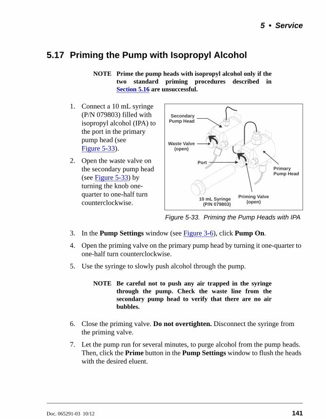
5 • Service
Doc. 065291-03 10/12 141
5.17 Priming the Pump with Isopropyl Alcohol
NOTE Prime the pump heads with isopropyl alcohol only if thetwo standard priming procedures described inSection 5.16 are unsuccessful.
1. Connect a 10 mL syringe (P/N 079803) filled with isopropyl alcohol (IPA) to the port in the primary pump head (see Figure 5-33).
2. Open the waste valve on the secondary pump head (see Figure 5-33) by turning the knob one-quarter to one-half turn counterclockwise.
Figure 5-33. Priming the Pump Heads with IPA
3. In the Pump Settings window (see Figure 3-6), click Pump On.
4. Open the priming valve on the primary pump head by turning it one-quarter to one-half turn counterclockwise.
5. Use the syringe to slowly push alcohol through the pump.
NOTE Be careful not to push any air trapped in the syringethrough the pump. Check the waste line from thesecondary pump head to verify that there are no airbubbles.
6. Close the priming valve. Do not overtighten. Disconnect the syringe from the priming valve.
7. Let the pump run for several minutes, to purge alcohol from the pump heads. Then, click the Prime button in the Pump Settings window to flush the heads with the desired eluent.
10 mL Syringe(P/N 079803)
Priming Valve (open)
Port
Waste Valve(open)
PrimaryPump Head
SecondaryPump Head
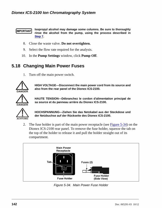
Dionex ICS-2100 Ion Chromatography System
142 Doc. 065291-03 10/12
8. Close the waste valve. Do not overtighten.
9. Select the flow rate required for the analysis.
10. In the Pump Settings window, click Pump Off.
5.18 Changing Main Power Fuses
1. Turn off the main power switch.
2. The fuse holder is part of the main power receptacle (see Figure 5-34) on the Dionex ICS-2100 rear panel. To remove the fuse holder, squeeze the tab on the top of the holder to release it and pull the holder straight out of its compartment.
Isopropyl alcohol may damage some columns. Be sure to thoroughlyrinse the alcohol from the pump, using the process described inStep 7.
HIGH VOLTAGE—Disconnect the main power cord from its source andalso from the rear panel of the Dionex ICS-2100.
HAUTE TENSION—Débranchez le cordon d'alimentation principal desa source et du panneau arrière du Dionex ICS-2100.
HOCHSPANNUNG—Ziehen Sie das Netzkabel aus der Steckdose undder Netzbuchse auf der Rückseite des Dionex ICS-2100.
Figure 5-34. Main Power Fuse Holder
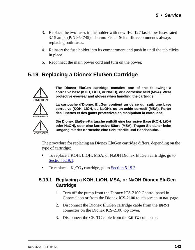
5 • Service
Doc. 065291-03 10/12 143
3. Replace the two fuses in the holder with new IEC 127 fast-blow fuses rated 3.15 amps (P/N 954745). Thermo Fisher Scientific recommends always replacing both fuses.
4. Reinsert the fuse holder into its compartment and push in until the tab clicks in place.
5. Reconnect the main power cord and turn on the power.
5.19 Replacing a Dionex EluGen Cartridge
The procedure for replacing an Dionex EluGen cartridge differs, depending on the type of cartridge:
• To replace a KOH, LiOH, MSA, or NaOH Dionex EluGen cartridge, go to Section 5.19.1.
• To replace a K2CO3 cartridge, go to Section 5.19.2.
5.19.1 Replacing a KOH, LiOH, MSA, or NaOH Dionex EluGen Cartridge
1. Turn off the pump from the Dionex ICS-2100 Control panel in Chromeleon or from the Dionex ICS-2100 touch screen HOME page.
2. Disconnect the Dionex EluGen cartridge cable from the EGC-1
connector on the Dionex ICS-2100 top cover.
3. Disconnect the CR-TC cable from the CR-TC connector.
The Dionex EluGen cartridge contains one of the following: acorrosive base (KOH, LiOH, or NaOH), or a corrosive acid (MSA). Wearprotective eyewear and gloves when handling the cartridge.
La cartouche d'Dionex EluGen contient un de ce qui suit: une basecorrosive (KOH, LiOH, ou NaOH), ou un acide corrosif (MSA). Porterdes lunettes et des gants protectives en manipulant la cartouche.
Die Dionex EluGen-Kartusche enthält eine korrosive Base (KOH, LiOHoder NaOH), oder eine korrosive Säure (MSA). Tragen Sie daher beimUmgang mit der Kartusche eine Schutzbrille und Handschuhe.
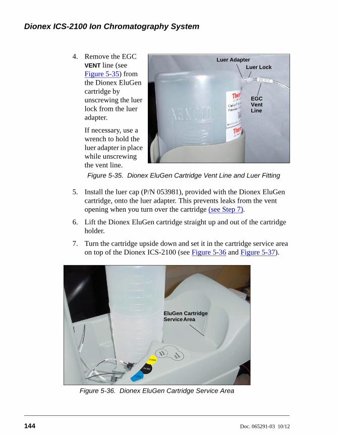
Dionex ICS-2100 Ion Chromatography System
144 Doc. 065291-03 10/12
4. Remove the EGC
VENT line (see Figure 5-35) from the Dionex EluGen cartridge by unscrewing the luer lock from the luer adapter.
If necessary, use a wrench to hold the luer adapter in place while unscrewing the vent line.
Figure 5-35. Dionex EluGen Cartridge Vent Line and Luer Fitting
5. Install the luer cap (P/N 053981), provided with the Dionex EluGen cartridge, onto the luer adapter. This prevents leaks from the vent opening when you turn over the cartridge (see Step 7).
6. Lift the Dionex EluGen cartridge straight up and out of the cartridge holder.
7. Turn the cartridge upside down and set it in the cartridge service area on top of the Dionex ICS-2100 (see Figure 5-36 and Figure 5-37).
Figure 5-36. Dionex EluGen Cartridge Service Area
Luer LockLuer Adapter
EGC VentLine
EluGen Cartridge AreaService
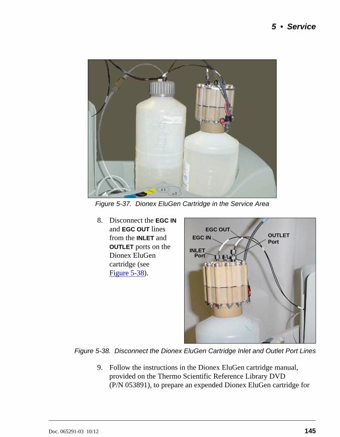
5 • Service
Doc. 065291-03 10/12 145
Figure 5-37. Dionex EluGen Cartridge in the Service Area
8. Disconnect the EGC IN and EGC OUT lines from the INLET and OUTLET ports on the Dionex EluGen cartridge (see Figure 5-38).
Figure 5-38. Disconnect the Dionex EluGen Cartridge Inlet and Outlet Port Lines
9. Follow the instructions in the Dionex EluGen cartridge manual, provided on the Thermo Scientific Reference Library DVD (P/N 053891), to prepare an expended Dionex EluGen cartridge for
EGC OUTOUTLETPort
EGC IN
INLETPort
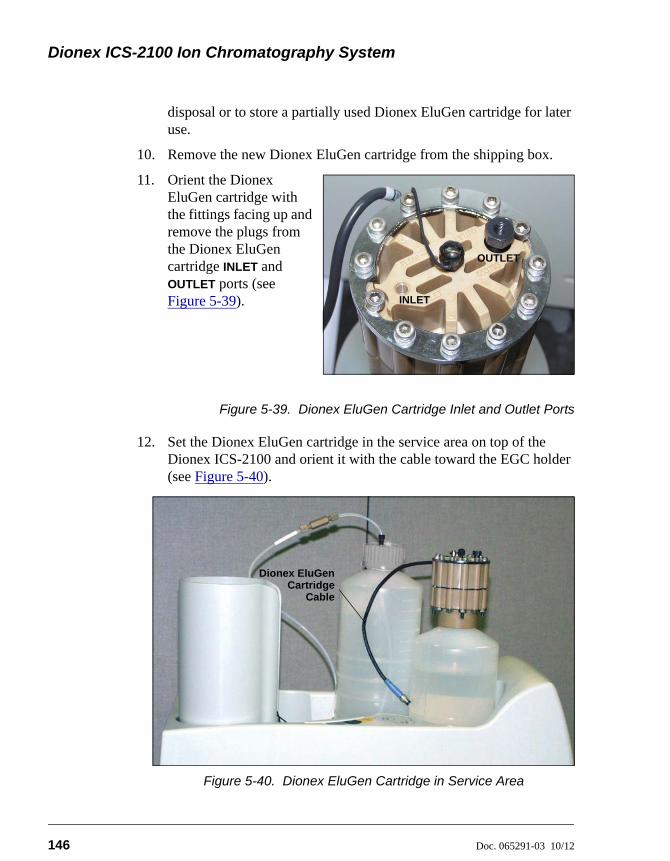
Dionex ICS-2100 Ion Chromatography System
146 Doc. 065291-03 10/12
disposal or to store a partially used Dionex EluGen cartridge for later use.
10. Remove the new Dionex EluGen cartridge from the shipping box.
11. Orient the Dionex EluGen cartridge with the fittings facing up and remove the plugs from the Dionex EluGen cartridge INLET and OUTLET ports (see Figure 5-39).
Figure 5-39. Dionex EluGen Cartridge Inlet and Outlet Ports
12. Set the Dionex EluGen cartridge in the service area on top of the Dionex ICS-2100 and orient it with the cable toward the EGC holder (see Figure 5-40).
Figure 5-40. Dionex EluGen Cartridge in Service Area
OUTLET
INLET
Dionex EluGenCartridge
Cable
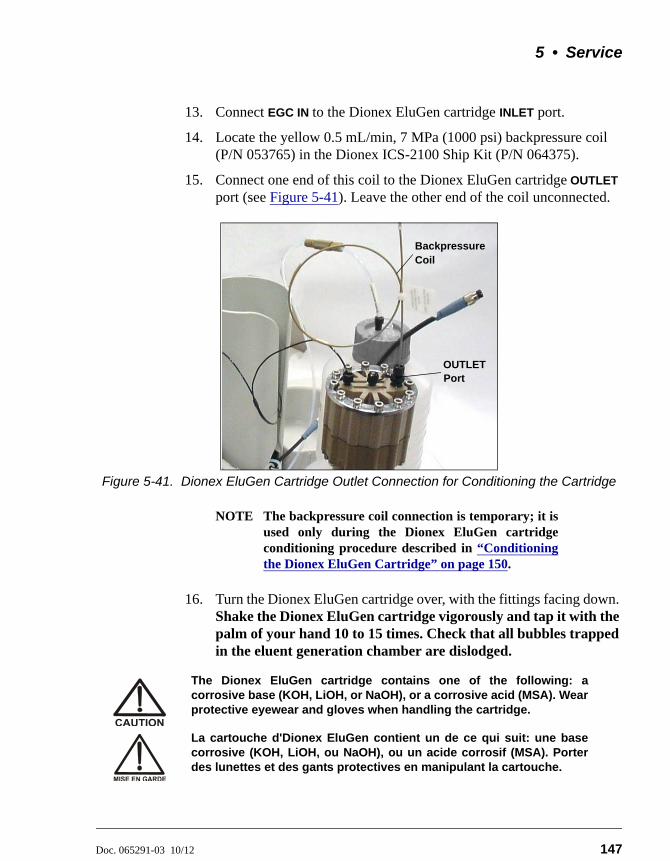
5 • Service
Doc. 065291-03 10/12 147
13. Connect EGC IN to the Dionex EluGen cartridge INLET port.
14. Locate the yellow 0.5 mL/min, 7 MPa (1000 psi) backpressure coil (P/N 053765) in the Dionex ICS-2100 Ship Kit (P/N 064375).
15. Connect one end of this coil to the Dionex EluGen cartridge OUTLET port (see Figure 5-41). Leave the other end of the coil unconnected.
Figure 5-41. Dionex EluGen Cartridge Outlet Connection for Conditioning the Cartridge
NOTE The backpressure coil connection is temporary; it isused only during the Dionex EluGen cartridgeconditioning procedure described in “Conditioningthe Dionex EluGen Cartridge” on page 150.
16. Turn the Dionex EluGen cartridge over, with the fittings facing down. Shake the Dionex EluGen cartridge vigorously and tap it with the palm of your hand 10 to 15 times. Check that all bubbles trapped in the eluent generation chamber are dislodged.
The Dionex EluGen cartridge contains one of the following: acorrosive base (KOH, LiOH, or NaOH), or a corrosive acid (MSA). Wearprotective eyewear and gloves when handling the cartridge.
La cartouche d'Dionex EluGen contient un de ce qui suit: une basecorrosive (KOH, LiOH, ou NaOH), ou un acide corrosif (MSA). Porterdes lunettes et des gants protectives en manipulant la cartouche.
BackpressureCoil
OUTLETPort
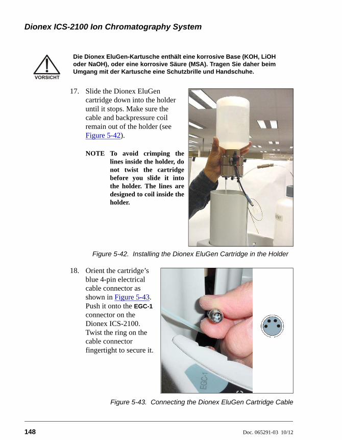
Dionex ICS-2100 Ion Chromatography System
148 Doc. 065291-03 10/12
17. Slide the Dionex EluGen cartridge down into the holder until it stops. Make sure the cable and backpressure coil remain out of the holder (see Figure 5-42).
NOTE To avoid crimping thelines inside the holder, donot twist the cartridgebefore you slide it intothe holder. The lines aredesigned to coil inside theholder.
Figure 5-42. Installing the Dionex EluGen Cartridge in the Holder
18. Orient the cartridge’s blue 4-pin electrical cable connector as shown in Figure 5-43. Push it onto the EGC-1 connector on the Dionex ICS-2100. Twist the ring on the cable connector fingertight to secure it.
Figure 5-43. Connecting the Dionex EluGen Cartridge Cable
Die Dionex EluGen-Kartusche enthält eine korrosive Base (KOH, LiOHoder NaOH), oder eine korrosive Säure (MSA). Tragen Sie daher beimUmgang mit der Kartusche eine Schutzbrille und Handschuhe.
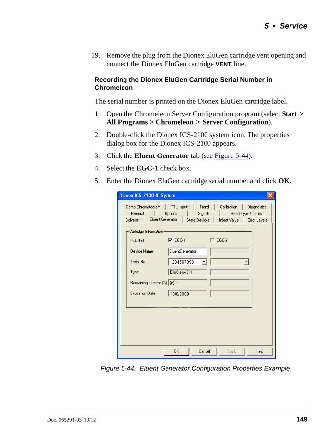
5 • Service
Doc. 065291-03 10/12 149
19. Remove the plug from the Dionex EluGen cartridge vent opening and connect the Dionex EluGen cartridge VENT line.
Recording the Dionex EluGen Cartridge Serial Number in Chromeleon
The serial number is printed on the Dionex EluGen cartridge label.
1. Open the Chromeleon Server Configuration program (select Start > All Programs > Chromeleon > Server Configuration).
2. Double-click the Dionex ICS-2100 system icon. The properties dialog box for the Dionex ICS-2100 appears.
3. Click the Eluent Generator tab (see Figure 5-44).
4. Select the EGC-1 check box.
5. Enter the Dionex EluGen cartridge serial number and click OK.
Figure 5-44. Eluent Generator Configuration Properties Example
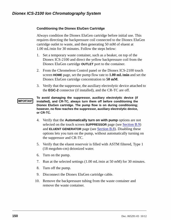
Dionex ICS-2100 Ion Chromatography System
150 Doc. 065291-03 10/12
Conditioning the Dionex EluGen Cartridge
Always condition the Dionex EluGen cartridge before initial use. This requires directing the backpressure coil connected to the Dionex EluGen cartridge outlet to waste, and then generating 50 mM of eluent at 1.00 mL/min for 30 minutes. Follow the steps below:
1. Set a temporary waste container, such as a beaker, on top of the Dionex ICS-2100 and direct the yellow backpressure coil from the Dionex EluGen cartridge OUTLET port to the container.
2. From the Chromeleon Control panel or the Dionex ICS-2100 touch screen HOME page, set the pump flow rate to 1.00 mL/min and set the Dionex EluGen cartridge concentration to 50 mM.
3. Verify that the suppressor, the auxiliary electrolytic device attached to the EGC-2 connector (if installed), and the CR-TC are off.
4. Verify that the Automatically turn on with pump options are not selected on the touch screen SUPPRESSOR page (see Section B.9) and ELUENT GENERATOR page (see Section B.8). Disabling these options lets you turn on the pump, without automatically turning on the suppressor and CR-TC.
5. Verify that the eluent reservoir is filled with ASTM filtered, Type 1 (18 megohm-cm) deionized water.
6. Turn on the pump.
7. Run at the selected settings (1.00 mL/min at 50 mM) for 30 minutes.
8. Turn off the pump.
9. Disconnect the Dionex EluGen cartridge cable.
10. Remove the backpressure tubing from the waste container and remove the waste container.
To avoid damaging the suppressor, auxiliary electrolytic device (ifinstalled), and CR-TC, always turn them off before conditioning theDionex EluGen cartridge. The pump flow is on during conditioning;however, no flow reaches the suppressor, auxiliary electrolytic device,or CR-TC.
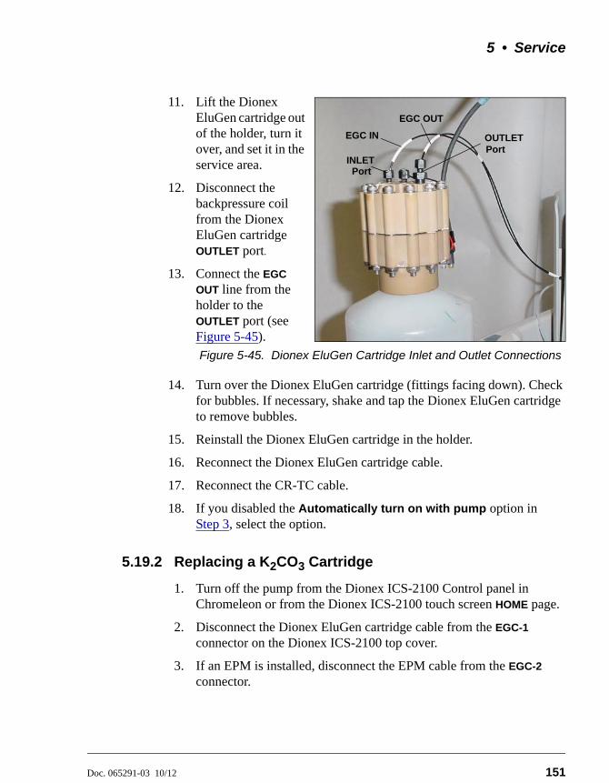
5 • Service
Doc. 065291-03 10/12 151
11. Lift the Dionex EluGen cartridge out of the holder, turn it over, and set it in the service area.
12. Disconnect the backpressure coil from the Dionex EluGen cartridge OUTLET port.
13. Connect the EGC
OUT line from the holder to the OUTLET port (see Figure 5-45).
Figure 5-45. Dionex EluGen Cartridge Inlet and Outlet Connections
14. Turn over the Dionex EluGen cartridge (fittings facing down). Check for bubbles. If necessary, shake and tap the Dionex EluGen cartridge to remove bubbles.
15. Reinstall the Dionex EluGen cartridge in the holder.
16. Reconnect the Dionex EluGen cartridge cable.
17. Reconnect the CR-TC cable.
18. If you disabled the Automatically turn on with pump option in Step 3, select the option.
5.19.2 Replacing a K2CO3 Cartridge
1. Turn off the pump from the Dionex ICS-2100 Control panel in Chromeleon or from the Dionex ICS-2100 touch screen HOME page.
2. Disconnect the Dionex EluGen cartridge cable from the EGC-1
connector on the Dionex ICS-2100 top cover.
3. If an EPM is installed, disconnect the EPM cable from the EGC-2 connector.
EGC OUT
OUTLETPort
EGC IN
INLETPort
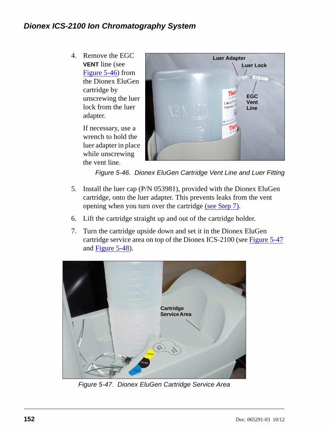
Dionex ICS-2100 Ion Chromatography System
152 Doc. 065291-03 10/12
4. Remove the EGC
VENT line (see Figure 5-46) from the Dionex EluGen cartridge by unscrewing the luer lock from the luer adapter.
If necessary, use a wrench to hold the luer adapter in place while unscrewing the vent line.
Figure 5-46. Dionex EluGen Cartridge Vent Line and Luer Fitting
5. Install the luer cap (P/N 053981), provided with the Dionex EluGen cartridge, onto the luer adapter. This prevents leaks from the vent opening when you turn over the cartridge (see Step 7).
6. Lift the cartridge straight up and out of the cartridge holder.
7. Turn the cartridge upside down and set it in the Dionex EluGen cartridge service area on top of the Dionex ICS-2100 (see Figure 5-47 and Figure 5-48).
Figure 5-47. Dionex EluGen Cartridge Service Area
Luer LockLuer Adapter
EGC VentLine
Cartridge AreaService
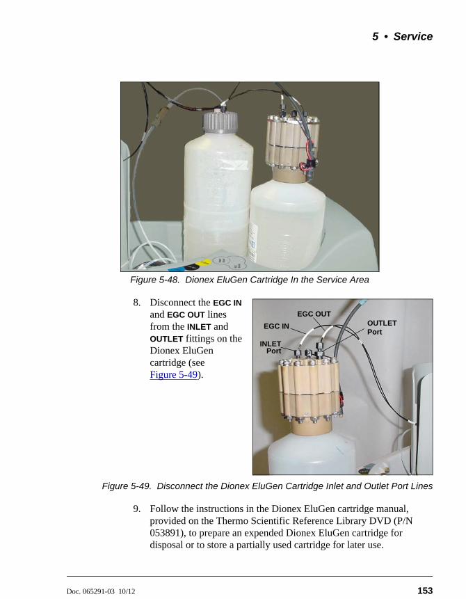
5 • Service
Doc. 065291-03 10/12 153
Figure 5-48. Dionex EluGen Cartridge In the Service Area
8. Disconnect the EGC IN and EGC OUT lines from the INLET and OUTLET fittings on the Dionex EluGen cartridge (see Figure 5-49).
Figure 5-49. Disconnect the Dionex EluGen Cartridge Inlet and Outlet Port Lines
9. Follow the instructions in the Dionex EluGen cartridge manual, provided on the Thermo Scientific Reference Library DVD (P/N 053891), to prepare an expended Dionex EluGen cartridge for disposal or to store a partially used cartridge for later use.
EGC OUTOUTLETPort
EGC IN
INLETPort
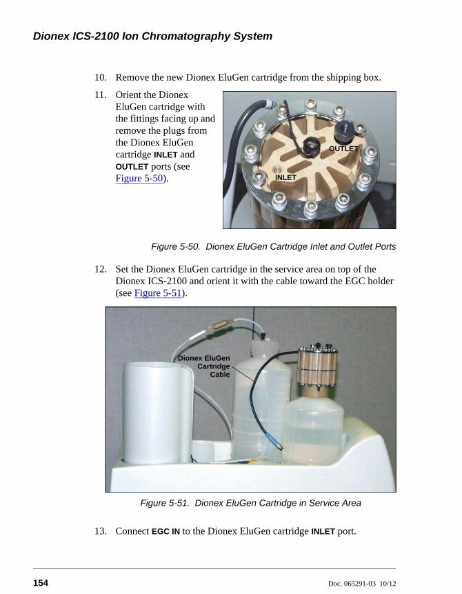
Dionex ICS-2100 Ion Chromatography System
154 Doc. 065291-03 10/12
10. Remove the new Dionex EluGen cartridge from the shipping box.
11. Orient the Dionex EluGen cartridge with the fittings facing up and remove the plugs from the Dionex EluGen cartridge INLET and OUTLET ports (see Figure 5-50).
Figure 5-50. Dionex EluGen Cartridge Inlet and Outlet Ports
12. Set the Dionex EluGen cartridge in the service area on top of the Dionex ICS-2100 and orient it with the cable toward the EGC holder (see Figure 5-51).
13. Connect EGC IN to the Dionex EluGen cartridge INLET port.
Figure 5-51. Dionex EluGen Cartridge in Service Area
OUTLET
INLET
Dionex EluGenCartridge
Cable
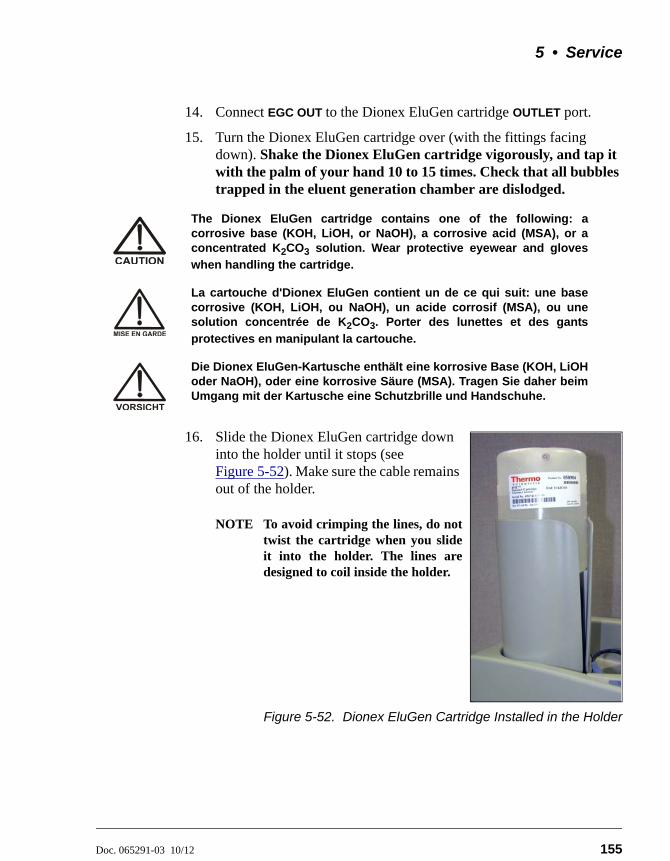
5 • Service
Doc. 065291-03 10/12 155
14. Connect EGC OUT to the Dionex EluGen cartridge OUTLET port.
15. Turn the Dionex EluGen cartridge over (with the fittings facing down). Shake the Dionex EluGen cartridge vigorously, and tap it with the palm of your hand 10 to 15 times. Check that all bubbles trapped in the eluent generation chamber are dislodged.
16. Slide the Dionex EluGen cartridge down into the holder until it stops (see Figure 5-52). Make sure the cable remains out of the holder.
NOTE To avoid crimping the lines, do nottwist the cartridge when you slideit into the holder. The lines aredesigned to coil inside the holder.
Figure 5-52. Dionex EluGen Cartridge Installed in the Holder
The Dionex EluGen cartridge contains one of the following: acorrosive base (KOH, LiOH, or NaOH), a corrosive acid (MSA), or aconcentrated K2CO3 solution. Wear protective eyewear and gloves
when handling the cartridge.
La cartouche d'Dionex EluGen contient un de ce qui suit: une basecorrosive (KOH, LiOH, ou NaOH), un acide corrosif (MSA), ou unesolution concentrée de K2CO3. Porter des lunettes et des gants
protectives en manipulant la cartouche.
Die Dionex EluGen-Kartusche enthält eine korrosive Base (KOH, LiOHoder NaOH), oder eine korrosive Säure (MSA). Tragen Sie daher beimUmgang mit der Kartusche eine Schutzbrille und Handschuhe.
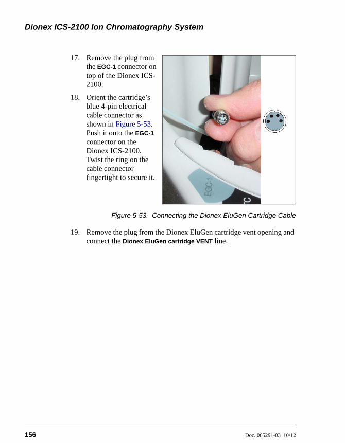
Dionex ICS-2100 Ion Chromatography System
156 Doc. 065291-03 10/12
17. Remove the plug from the EGC-1 connector on top of the Dionex ICS-2100.
18. Orient the cartridge’s blue 4-pin electrical cable connector as shown in Figure 5-53. Push it onto the EGC-1 connector on the Dionex ICS-2100. Twist the ring on the cable connector fingertight to secure it.
Figure 5-53. Connecting the Dionex EluGen Cartridge Cable
19. Remove the plug from the Dionex EluGen cartridge vent opening and connect the Dionex EluGen cartridge VENT line.
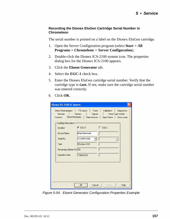
5 • Service
Doc. 065291-03 10/12 157
Recording the Dionex EluGen Cartridge Serial Number in Chromeleon
The serial number is printed on a label on the Dionex EluGen cartridge.
1. Open the Server Configuration program (select Start > All Programs > Chromeleon > Server Configuration).
2. Double-click the Dionex ICS-2100 system icon. The properties dialog box for the Dionex ICS-2100 appears.
3. Click the Eluent Generator tab.
4. Select the EGC-1 check box.
5. Enter the Dionex EluGen cartridge serial number. Verify that the cartridge type is Carb. If not, make sure the cartridge serial number was entered correctly.
6. Click OK.
Figure 5-54. Eluent Generator Configuration Properties Example
Dionex ICS-2100 Ion Chromatography System
158 Doc. 065291-03 10/12
Continue on to one of the following sections, depending on the type of eluent to be generated:
• For carbonate eluent, go to “Plumbing the Dionex EluGen Cartridge for Conditioning with Carbonate Eluent” on page 159.
• For carbonate/bicarbonate eluent, go to “Plumbing the Dionex EluGen Cartridge and EPM for Conditioning with Carbonate/Bicarbonate Eluent” on page 162.
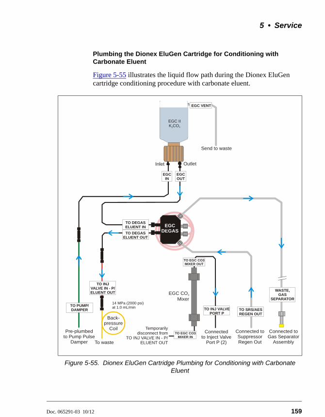
5 • Service
Doc. 065291-03 10/12 159
Plumbing the Dionex EluGen Cartridge for Conditioning with Carbonate Eluent
Figure 5-55 illustrates the liquid flow path during the Dionex EluGen cartridge conditioning procedure with carbonate eluent.
Figure 5-55. Dionex EluGen Cartridge Plumbing for Conditioning with Carbonate Eluent
EGC DEGAS
EGC IN
Connected toGas Separator
Assembly
TO DEGASELUENT OUT
TO SRS/AESREGEN OUT
WASTE, GAS
SEPARATOR
Connected toSuppressorRegen Out
Pre-plumbed Pump Pulse
Damperto
Inlet Outlet
EGC VENT
Send to waste
EGC OUT
EGC II K CO2 3
TO DEGASELUENT IN
Back-pressure
Coil
TO INJ VALVE IN - P/ELUENT OUT
To waste
14 MPa (2000 psi) at 1.0 mL/min
Connected Inject ValvePort P (2)
to
EGC CO Mixer
3
TO EGC CO3 MIXER IN
TO EGC CO3 MIXER OUT
TO INJ VALVE PORT P
Temporarily disconnect from
TO INJ VALVE IN - P/ ELUENT OUT
TO PUMP/DAMPER
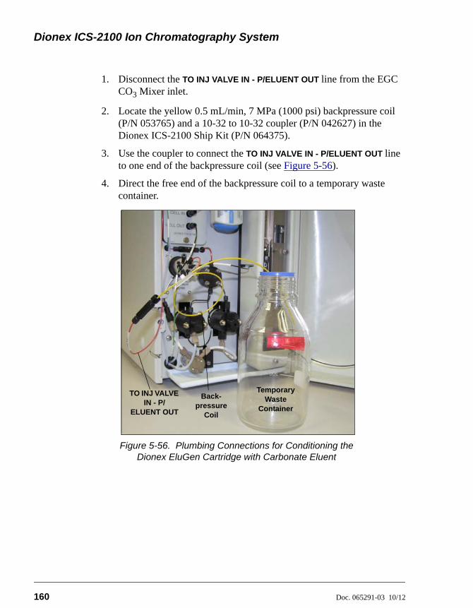
Dionex ICS-2100 Ion Chromatography System
160 Doc. 065291-03 10/12
1. Disconnect the TO INJ VALVE IN - P/ELUENT OUT line from the EGC CO3 Mixer inlet.
2. Locate the yellow 0.5 mL/min, 7 MPa (1000 psi) backpressure coil (P/N 053765) and a 10-32 to 10-32 coupler (P/N 042627) in the Dionex ICS-2100 Ship Kit (P/N 064375).
3. Use the coupler to connect the TO INJ VALVE IN - P/ELUENT OUT line to one end of the backpressure coil (see Figure 5-56).
4. Direct the free end of the backpressure coil to a temporary waste container.
Figure 5-56. Plumbing Connections for Conditioning the Dionex EluGen Cartridge with Carbonate Eluent
EGC Cable
Temporary Waste
Container
Back-pressure
Coil
TO INJ VALVE IN - P/
ELUENT OUT
5 • Service
Doc. 065291-03 10/12 161
Conditioning the Dionex EluGen Cartridge
Always condition the Dionex EluGen cartridge for 30 minutes before initial use.
1. Make sure the eluent reservoir is filled with ASTM filtered, Type I (18-megohm) deionized water.
2. Verify that the suppressor and the auxiliary electrolytic device attached to the EGC-2 connector (if installed) are off.
3. Verify that the Automatically turn on with pump option is not selected on the Dionex ICS-2100 touch screen SUPPRESSOR page (see Section B.9). Disabling this option lets you turn on the pump, without automatically turning on the suppressor.
4. From the Control panel in Chromeleon or the touch screen HOME
page, set the pump flow rate to 1.00 mL/min.
5. Turn on the pump.
6. From the Chromeleon Control panel or the touch screen ELUENT
GENERATOR page, set the EGC-1 concentration to 9 mM.
7. Turn on the EGC-1 current.
8. Run at these settings for 30 minutes.
9. Turn off the EGC-1 current.
10. Turn off the pump.
11. Remove the backpressure coil.
12. Reconnect the TO INJ VALVE IN - P/ELUENT OUT line to the mixer inlet.
To avoid damaging the suppressor (and auxiliary electrolytic device, ifinstalled), always turn them off before conditioning the Dionex EluGencartridge. The pump flow is on during conditioning; however, no flowreaches the suppressor or auxiliary electrolytic device.
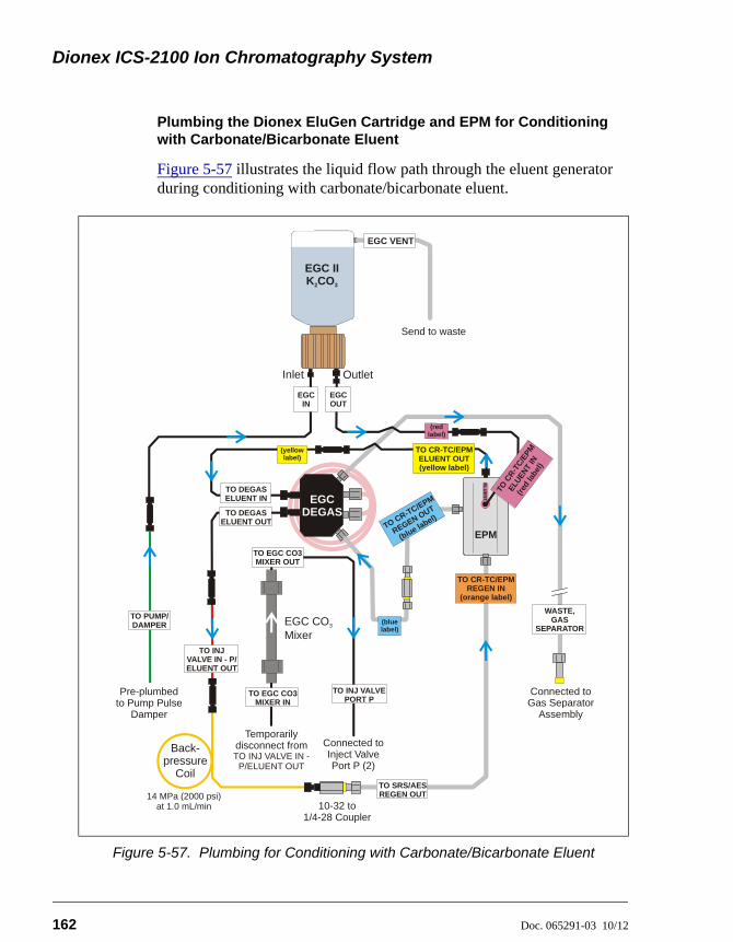
Dionex ICS-2100 Ion Chromatography System
162 Doc. 065291-03 10/12
Plumbing the Dionex EluGen Cartridge and EPM for Conditioning with Carbonate/Bicarbonate Eluent
Figure 5-57 illustrates the liquid flow path through the eluent generator during conditioning with carbonate/bicarbonate eluent.
Figure 5-57. Plumbing for Conditioning with Carbonate/Bicarbonate Eluent
EGC IN
TO DEGASELUENT OUT
TO SRS/AESREGEN OUT
WASTE, GAS
SEPARATOR
TO INJ VALVE IN - P/ELUENT OUT
EGC VENT
TO DEGASELUENT IN EGC
DEGAS
Connected toGas Separator
Assembly
Connected Inject ValvePort P (2)
to
Pre-plumbed Pump Pulse
Damperto
Inlet Outlet
Send to waste
EGC CO Mixer
3
EGC II K CO2 3
TO CR-TC/EPM REGEN IN
(orange label)
TO PUMP/DAMPER
TO CR-TC/EPM ELUENT OUT (yellow label)
TO CR-TC/EPM
REGEN OUT
(blue label)
EPM
EL
UE
NT
IN
TO C
R-T
C/E
PM
ELU
ENT
IN
(red
labe
l)
EGC OUT
TO EGC CO3 MIXER IN
TO INJ VALVE PORT P
TO EGC CO3 MIXER OUT
(yellowlabel)
(blue label)
(redlabel)
Back-pressure
Coil
10-32 to 1/4-28 Coupler
14 MPa (2000 psi) at 1.0 mL/min
Temporarily disconnect from TO INJ VALVE IN -
P/ELUENT OUT
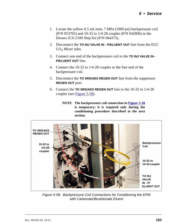
5 • Service
Doc. 065291-03 10/12 163
1. Locate the yellow 0.5 mL/min, 7 MPa (1000 psi) backpressure coil (P/N 053765) and 10-32 to 1/4-28 coupler (P/N 042806) in the Dionex ICS-2100 Ship Kit (P/N 064375).
2. Disconnect the TO INJ VALVE IN - P/ELUENT OUT line from the EGC CO3 Mixer inlet.
3. Connect one end of the backpressure coil to the TO INJ VALVE IN -
P/ELUENT OUT line.
4. Connect the 10-32 to 1/4-28 coupler to the free end of the backpressure coil.
5. Disconnect the TO SRS/AES REGEN OUT line from the suppressor REGEN OUT port.
6. Connect the TO SRS/AES REGEN OUT line to the 10-32 to 1/4-28 coupler (see Figure 5-58).
NOTE The backpressure coil connection in Figure 5-58is temporary; it is required only during theconditioning procedure described in the nextsection.
Figure 5-58. Backpressure Coil Connections for Conditioning the EPM with Carbonate/Bicarbonate Eluent
10-32 to1/4-28
coupler
TO INJ VALVE IN - P/ELUENT OUT
BackpressureCoil
TO SRS/AESREGEN OUT
10-32 to 10-32 coupler
Dionex ICS-2100 Ion Chromatography System
164 Doc. 065291-03 10/12
Conditioning the Dionex EluGen Cartridge
Always condition the Dionex EluGen cartridge for 30 minutes before initial use.
1. Make sure the eluent reservoir is filled with ASTM filtered, Type I (18-megohm) deionized water.
2. Verify that the suppressor and the auxiliary electrolytic device (if installed) are off.
3. Verify that the Automatically turn on with pump option is not selected on the Dionex ICS-2100 touch screen SUPPRESSOR page (see Section B.9). Disabling this option lets you turn on the pump, without automatically turning on the suppressor.
4. From the Dionex ICS-2100 Control panel in Chromeleon or the touch screen HOME page, set the pump flow rate to 1.00 mL/min.
5. Turn on the pump.
6. Select the following settings from the Chromeleon Control panel or the touch screen ELUENT GENERATOR page:
• Set the EGC-1 concentration to 9 mM.
• Set the EGC-2 concentration to 1 mM.
7. Turn on the EGC-1 and EGC-2 currents.
8. Run at these settings for 30 minutes.
9. Turn off the EGC-1 and EGC-2 currents.
10. Turn off the pump.
11. Remove the backpressure coil.
12. Reconnect the TO INJ VALVE IN - P/ELUENT OUT line to the mixer inlet.
13. Reconnect the TO SRS/AES REGEN OUT line to the suppressor REGEN
OUT port.
To avoid damaging the suppressor (and auxiliary electrolytic device, ifinstalled), always turn them off before conditioning the Dionex EluGencartridge. The pump flow is on during conditioning; however, no flowreaches the suppressor or auxiliary electrolytic device.
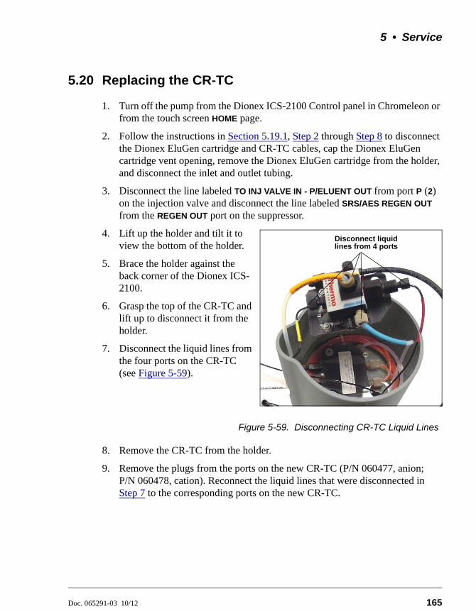
5 • Service
Doc. 065291-03 10/12 165
5.20 Replacing the CR-TC
1. Turn off the pump from the Dionex ICS-2100 Control panel in Chromeleon or from the touch screen HOME page.
2. Follow the instructions in Section 5.19.1, Step 2 through Step 8 to disconnect the Dionex EluGen cartridge and CR-TC cables, cap the Dionex EluGen cartridge vent opening, remove the Dionex EluGen cartridge from the holder, and disconnect the inlet and outlet tubing.
3. Disconnect the line labeled TO INJ VALVE IN - P/ELUENT OUT from port P (2) on the injection valve and disconnect the line labeled SRS/AES REGEN OUT from the REGEN OUT port on the suppressor.
4. Lift up the holder and tilt it to view the bottom of the holder.
5. Brace the holder against the back corner of the Dionex ICS-2100.
6. Grasp the top of the CR-TC and lift up to disconnect it from the holder.
7. Disconnect the liquid lines from the four ports on the CR-TC (see Figure 5-59).
Figure 5-59. Disconnecting CR-TC Liquid Lines
8. Remove the CR-TC from the holder.
9. Remove the plugs from the ports on the new CR-TC (P/N 060477, anion; P/N 060478, cation). Reconnect the liquid lines that were disconnected in Step 7 to the corresponding ports on the new CR-TC.
Disconnect liquid lines from 4 ports
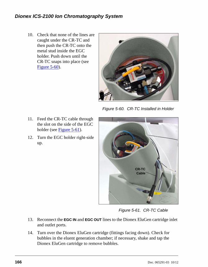
Dionex ICS-2100 Ion Chromatography System
166 Doc. 065291-03 10/12
10. Check that none of the lines are caught under the CR-TC and then push the CR-TC onto the metal stud inside the EGC holder. Push down until the CR-TC snaps into place (see Figure 5-60).
Figure 5-60. CR-TC Installed in Holder
11. Feed the CR-TC cable through the slot on the side of the EGC holder (see Figure 5-61).
12. Turn the EGC holder right-side up.
Figure 5-61. CR-TC Cable
13. Reconnect the EGC IN and EGC OUT lines to the Dionex EluGen cartridge inlet and outlet ports.
14. Turn over the Dionex EluGen cartridge (fittings facing down). Check for bubbles in the eluent generation chamber; if necessary, shake and tap the Dionex EluGen cartridge to remove bubbles.
CR-TCCable
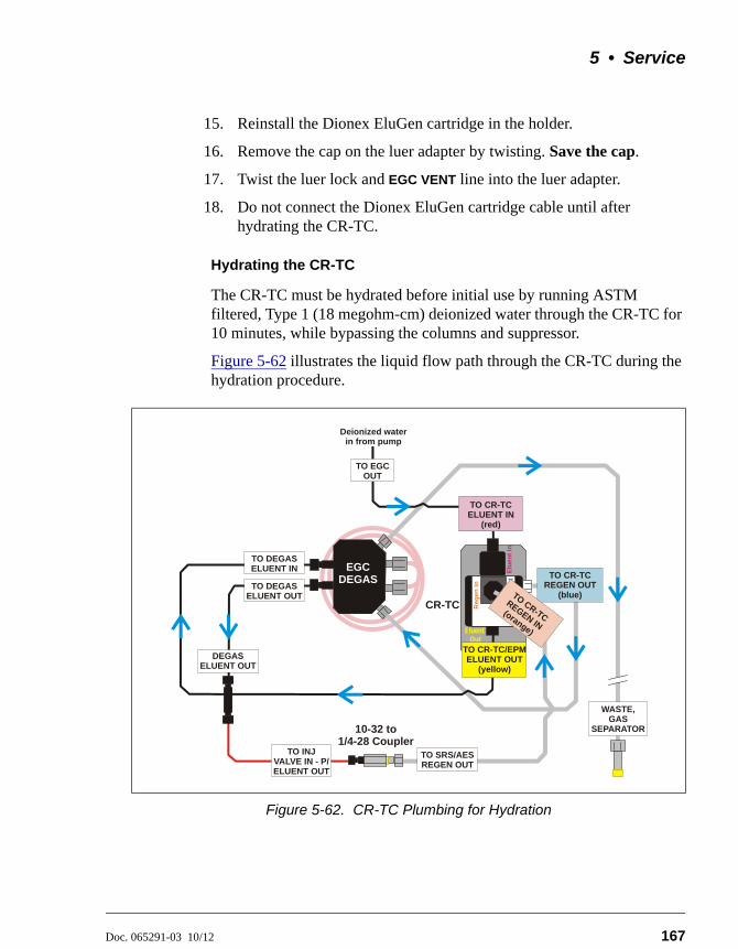
5 • Service
Doc. 065291-03 10/12 167
15. Reinstall the Dionex EluGen cartridge in the holder.
16. Remove the cap on the luer adapter by twisting. Save the cap.
17. Twist the luer lock and EGC VENT line into the luer adapter.
18. Do not connect the Dionex EluGen cartridge cable until after hydrating the CR-TC.
Hydrating the CR-TC
The CR-TC must be hydrated before initial use by running ASTM filtered, Type 1 (18 megohm-cm) deionized water through the CR-TC for 10 minutes, while bypassing the columns and suppressor.
Figure 5-62 illustrates the liquid flow path through the CR-TC during the hydration procedure.
Figure 5-62. CR-TC Plumbing for Hydration
Elu
en
t In
Reg
en
In
Re
ge
n O
ut
Eluent Out
CR-TC
EGC DEGAS
TO DEGASELUENT OUT
TO CR-TC REGEN OUT
(blue)
TO SRS/AESREGEN OUT
TO CR-TC
REGEN IN(orange)
WASTE, GAS
SEPARATOR
DEGASELUENT OUT
TO INJ VALVE IN - P/ELUENT OUT
TO DEGASELUENT IN
TO CR-TCELUENT IN
(red)
TO CR-TC/EPMELUENT OUT
(yellow)
10-32 to 1/4-28 Coupler
Deionized water in from pump
TO EGC OUT
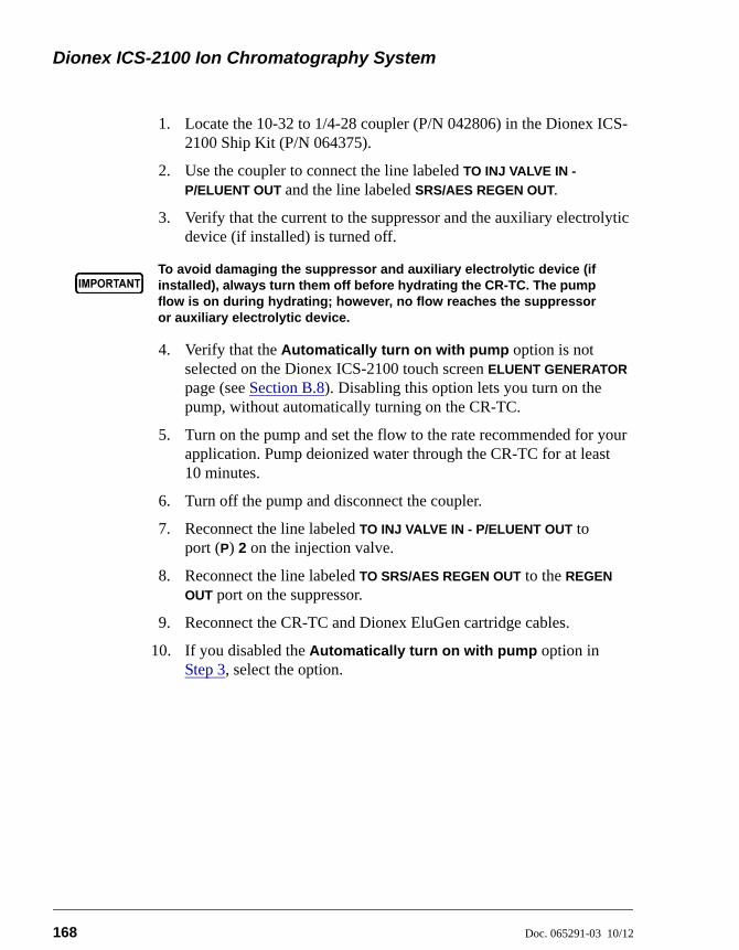
Dionex ICS-2100 Ion Chromatography System
168 Doc. 065291-03 10/12
1. Locate the 10-32 to 1/4-28 coupler (P/N 042806) in the Dionex ICS-2100 Ship Kit (P/N 064375).
2. Use the coupler to connect the line labeled TO INJ VALVE IN -
P/ELUENT OUT and the line labeled SRS/AES REGEN OUT.
3. Verify that the current to the suppressor and the auxiliary electrolytic device (if installed) is turned off.
4. Verify that the Automatically turn on with pump option is not selected on the Dionex ICS-2100 touch screen ELUENT GENERATOR page (see Section B.8). Disabling this option lets you turn on the pump, without automatically turning on the CR-TC.
5. Turn on the pump and set the flow to the rate recommended for your application. Pump deionized water through the CR-TC for at least 10 minutes.
6. Turn off the pump and disconnect the coupler.
7. Reconnect the line labeled TO INJ VALVE IN - P/ELUENT OUT to port (P) 2 on the injection valve.
8. Reconnect the line labeled TO SRS/AES REGEN OUT to the REGEN
OUT port on the suppressor.
9. Reconnect the CR-TC and Dionex EluGen cartridge cables.
10. If you disabled the Automatically turn on with pump option in Step 3, select the option.
To avoid damaging the suppressor and auxiliary electrolytic device (ifinstalled), always turn them off before hydrating the CR-TC. The pumpflow is on during hydrating; however, no flow reaches the suppressoror auxiliary electrolytic device.
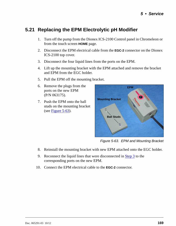
5 • Service
Doc. 065291-03 10/12 169
5.21 Replacing the EPM Electrolytic pH Modifier
1. Turn off the pump from the Dionex ICS-2100 Control panel in Chromeleon or from the touch screen HOME page.
2. Disconnect the EPM electrical cable from the EGC-2 connector on the Dionex ICS-2100 top cover.
3. Disconnect the four liquid lines from the ports on the EPM.
4. Lift up the mounting bracket with the EPM attached and remove the bracket and EPM from the EGC holder.
5. Pull the EPM off the mounting bracket.
6. Remove the plugs from the ports on the new EPM (P/N 063175).
7. Push the EPM onto the ball studs on the mounting bracket (see Figure 5-63).
Figure 5-63. EPM and Mounting Bracket
8. Reinstall the mounting bracket with new EPM attached onto the EGC holder.
9. Reconnect the liquid lines that were disconnected in Step 3 to the corresponding ports on the new EPM.
10. Connect the EPM electrical cable to the EGC-2 connector.
EGC Cable
Ball Studs
Mounting Bracket
EPM
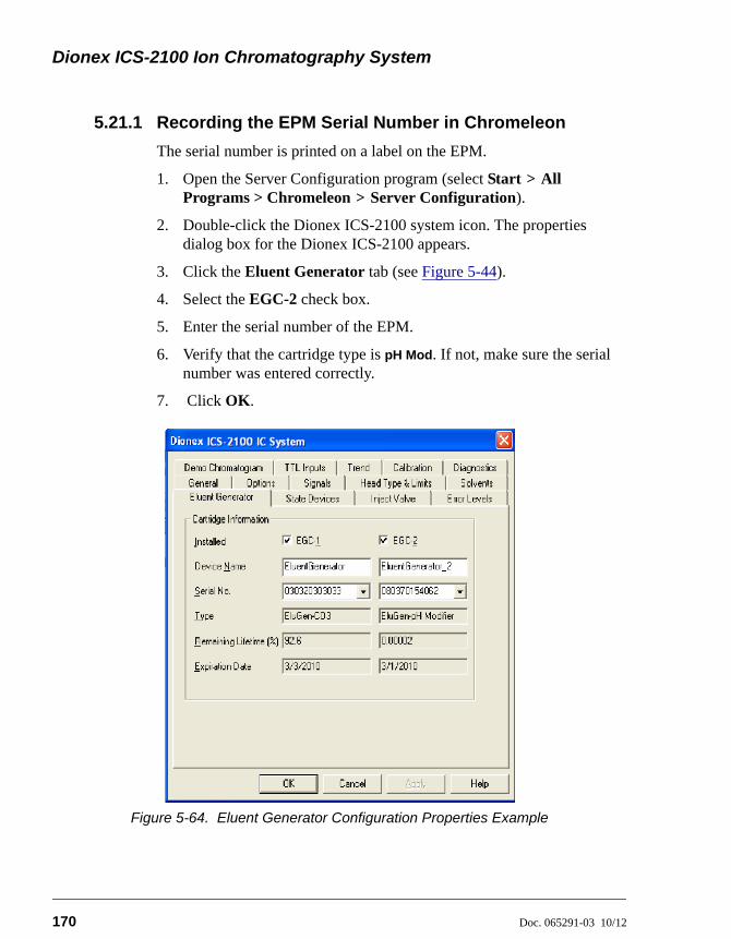
Dionex ICS-2100 Ion Chromatography System
170 Doc. 065291-03 10/12
5.21.1 Recording the EPM Serial Number in Chromeleon
The serial number is printed on a label on the EPM.
1. Open the Server Configuration program (select Start > All Programs > Chromeleon > Server Configuration).
2. Double-click the Dionex ICS-2100 system icon. The properties dialog box for the Dionex ICS-2100 appears.
3. Click the Eluent Generator tab (see Figure 5-44).
4. Select the EGC-2 check box.
5. Enter the serial number of the EPM.
6. Verify that the cartridge type is pH Mod. If not, make sure the serial number was entered correctly.
7. Click OK.
Figure 5-64. Eluent Generator Configuration Properties Example
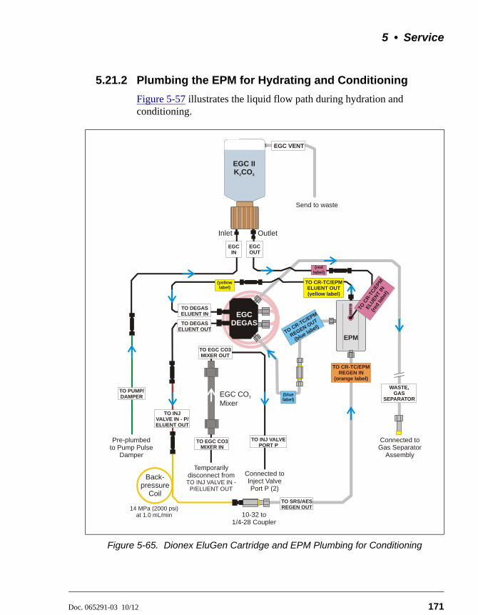
5 • Service
Doc. 065291-03 10/12 171
5.21.2 Plumbing the EPM for Hydrating and Conditioning
Figure 5-57 illustrates the liquid flow path during hydration and conditioning.
Figure 5-65. Dionex EluGen Cartridge and EPM Plumbing for Conditioning
EGC IN
TO DEGASELUENT OUT
TO SRS/AESREGEN OUT
WASTE, GAS
SEPARATOR
TO INJ VALVE IN - P/ELUENT OUT
EGC VENT
TO DEGASELUENT IN EGC
DEGAS
Connected toGas Separator
Assembly
Connected Inject ValvePort P (2)
to
Pre-plumbed Pump Pulse
Damperto
Inlet Outlet
Send to waste
EGC CO Mixer
3
EGC II K CO2 3
TO CR-TC/EPM REGEN IN
(orange label)
TO PUMP/DAMPER
TO CR-TC/EPM ELUENT OUT (yellow label)
TO CR-TC/EPM
REGEN OUT
(blue label)
EPM
EL
UE
NT
IN
TO C
R-T
C/E
PM
ELU
ENT
IN
(red
labe
l)
EGC OUT
TO EGC CO3 MIXER IN
TO INJ VALVE PORT P
TO EGC CO3 MIXER OUT
(yellowlabel)
(blue label)
(redlabel)
Back-pressure
Coil
10-32 to 1/4-28 Coupler
14 MPa (2000 psi) at 1.0 mL/min
Temporarily disconnect from TO INJ VALVE IN -
P/ELUENT OUT
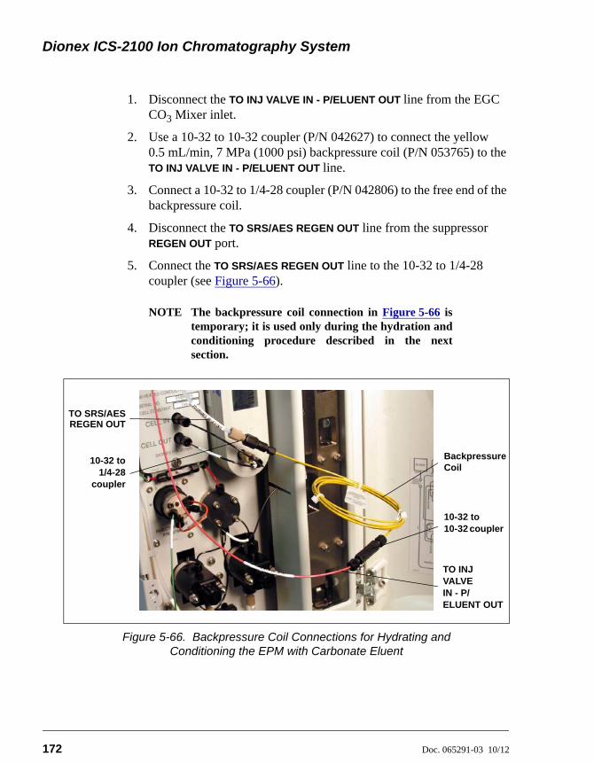
Dionex ICS-2100 Ion Chromatography System
172 Doc. 065291-03 10/12
1. Disconnect the TO INJ VALVE IN - P/ELUENT OUT line from the EGC CO3 Mixer inlet.
2. Use a 10-32 to 10-32 coupler (P/N 042627) to connect the yellow 0.5 mL/min, 7 MPa (1000 psi) backpressure coil (P/N 053765) to the TO INJ VALVE IN - P/ELUENT OUT line.
3. Connect a 10-32 to 1/4-28 coupler (P/N 042806) to the free end of the backpressure coil.
4. Disconnect the TO SRS/AES REGEN OUT line from the suppressor REGEN OUT port.
5. Connect the TO SRS/AES REGEN OUT line to the 10-32 to 1/4-28 coupler (see Figure 5-66).
NOTE The backpressure coil connection in Figure 5-66 istemporary; it is used only during the hydration andconditioning procedure described in the nextsection.
Figure 5-66. Backpressure Coil Connections for Hydrating and Conditioning the EPM with Carbonate Eluent
10-32 to1/4-28
coupler
TO INJ VALVE IN - P/ELUENT OUT
BackpressureCoil
TO SRS/AESREGEN OUT
10-32 to 10-32 coupler
5 • Service
Doc. 065291-03 10/12 173
5.21.3 Hydrating and Conditioning the EPM
Follow the steps below to hydrate the EPM for 5 minutes and then condition the EPM for 30 minutes.
1. Fill the eluent reservoir with ASTM filtered, Type I (18-megohm) deionized water.
2. Verify that the suppressor and the auxiliary electrolytic device (if installed) are off.
3. Verify that the Dionex EluGen cartridge is off.
4. Verify that the Automatically turn on with pump options are not selected on the Dionex ICS-2100 touch screen SUPPRESSOR page (see Section B.9) and ELUENT GENERATOR page (see Section B.8). Disabling these options lets you turn on the pump, without automatically turning on the suppressor and Dionex EluGen cartridge.
5. From the Dionex ICS-2100 Control panel in Chromeleon or the Dionex ICS-2100 touch screen HOME page, set the pump flow rate to 1.00 mL/min.
6. Turn on the pump.
7. Run the pump for 5 minutes to hydrate the EPM.
8. Select the following settings from the Chromeleon Control panel or the touch screen ELUENT GENERATOR page:
• Set the EGC-1 concentration to 9 mM.
• Set the EGC-2 concentration to 1 mM.
9. Turn on the EGC-1 and EGC-2 currents.
10. Run at these settings for 30 minutes.
11. Turn off the EGC-1 and EGC-2 currents.
12. Turn off the pump.
To avoid damaging the suppressor and auxiliary electrolytic device (ifinstalled), always turn them off before conditioning the EPM andDionex EluGen cartridge. The pump flow is on during conditioning;however, no flow reaches the suppressor or auxiliary electrolyticdevice.

Dionex ICS-2100 Ion Chromatography System
174 Doc. 065291-03 10/12
13. Remove the backpressure coil and couplers from the TO INJ VALVE IN
- P/ELUENT OUT and TO SRS/AES REGEN OUT lines.
14. Reconnect the TO INJ VALVE IN - P/ELUENT OUT line to the EGC CO3 Mixer inlet.
15. Reconnect the TO SRS/AES REGEN OUT line to the suppressor REGEN
OUT port.
5.22 Replacing the EGC CO3 Mixer
5.22.1 Installing the New EGC CO3 Mixer
1. Turn off the pump from the Dionex ICS-2100 Control panel in Chromeleon or from the touch screen HOME page.
2. Disconnect the inlet and outlet lines (labeled TO EGC CO3 MIXER IN and TO EGC CO3 MIXER OUT) from the existing mixer and pull the mixer off the mounting clips.
3. Orient the new EGC CO3 Mixer (P/N 079943) with the outlet pointing upward and push it onto the mounting clips (see Figure 5-67). The mixer outlet must point upward to ensure thorough mixing of the eluent.
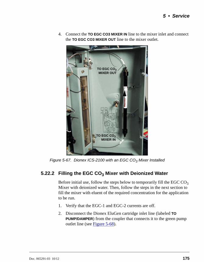
5 • Service
Doc. 065291-03 10/12 175
4. Connect the TO EGC CO3 MIXER IN line to the mixer inlet and connect the TO EGC CO3 MIXER OUT line to the mixer outlet.
5.22.2 Filling the EGC CO3 Mixer with Deionized Water
Before initial use, follow the steps below to temporarily fill the EGC CO3 Mixer with deionized water. Then, follow the steps in the next section to fill the mixer with eluent of the required concentration for the application to be run.
1. Verify that the EGC-1 and EGC-2 currents are off.
2. Disconnect the Dionex EluGen cartridge inlet line (labeled TO
PUMP/DAMPER) from the coupler that connects it to the green pump outlet line (see Figure 5-68).
Figure 5-67. Dionex ICS-2100 with an EGC CO3 Mixer Installed
TO EGC CO3MIXER IN
TO EGC CO3MIXER OUT
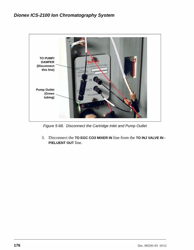
Dionex ICS-2100 Ion Chromatography System
176 Doc. 065291-03 10/12
3. Disconnect the TO EGC CO3 MIXER IN line from the TO INJ VALVE IN -
P/ELUENT OUT line.
Figure 5-68. Disconnect the Cartridge Inlet and Pump Outlet
TO PUMP/DAMPER
(Disconnectthis line)
Pump Outlet(Greentubing)
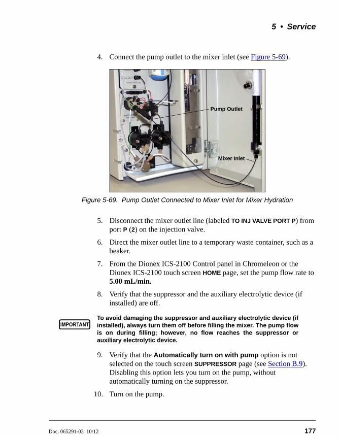
5 • Service
Doc. 065291-03 10/12 177
4. Connect the pump outlet to the mixer inlet (see Figure 5-69).
5. Disconnect the mixer outlet line (labeled TO INJ VALVE PORT P) from port P (2) on the injection valve.
6. Direct the mixer outlet line to a temporary waste container, such as a beaker.
7. From the Dionex ICS-2100 Control panel in Chromeleon or the Dionex ICS-2100 touch screen HOME page, set the pump flow rate to 5.00 mL/min.
8. Verify that the suppressor and the auxiliary electrolytic device (if installed) are off.
9. Verify that the Automatically turn on with pump option is not selected on the touch screen SUPPRESSOR page (see Section B.9). Disabling this option lets you turn on the pump, without automatically turning on the suppressor.
10. Turn on the pump.
Figure 5-69. Pump Outlet Connected to Mixer Inlet for Mixer Hydration
To avoid damaging the suppressor and auxiliary electrolytic device (ifinstalled), always turn them off before filling the mixer. The pump flowis on during filling; however, no flow reaches the suppressor orauxiliary electrolytic device.
Mixer Inlet
Pump Outlet
Dionex ICS-2100 Ion Chromatography System
178 Doc. 065291-03 10/12
11. Run the pump until the mixer is filled and there is a consistent flow of water exiting the mixer outlet.
It takes about 5 minutes to fill a 4-mm mixer and about 2 minutes to fill a 2-mm mixer.
12. Turn off the pump.
5.22.3 Filling the EGC CO3 Mixer with Eluent
Before initial use, follow the steps in this section to fill the EGC CO3 Mixer with the eluent required for the application to be run. The procedure varies slightly, depending on the type of eluent to be generated:
• For carbonate eluent, see “Filling the EGC CO3 Mixer with Carbonate Eluent” below.
• For carbonate/bicarbonate eluent, see “Filling the EGC CO3 Mixer with Carbonate/Bicarbonate Eluent” on page 182.
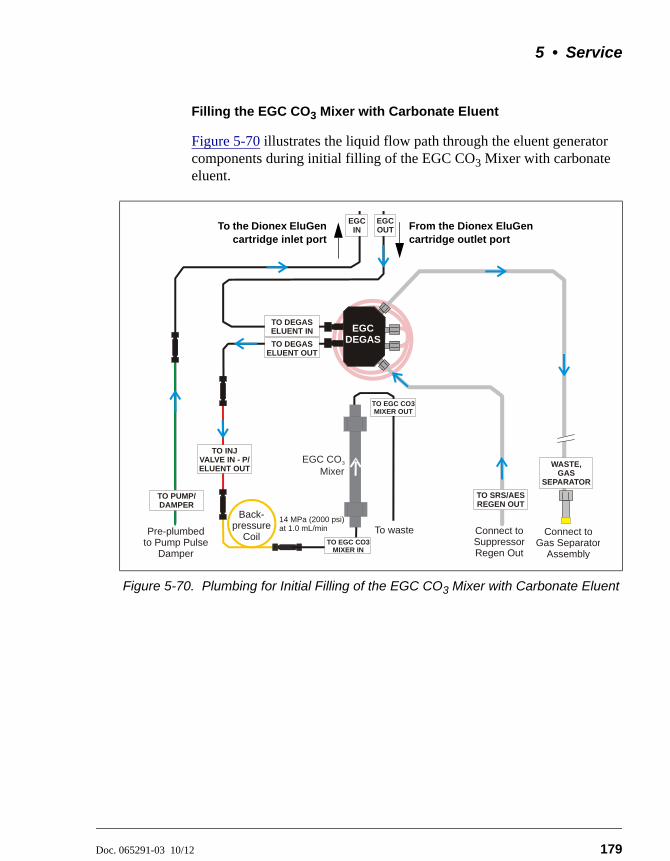
5 • Service
Doc. 065291-03 10/12 179
Filling the EGC CO3 Mixer with Carbonate Eluent
Figure 5-70 illustrates the liquid flow path through the eluent generator components during initial filling of the EGC CO3 Mixer with carbonate eluent.
Figure 5-70. Plumbing for Initial Filling of the EGC CO3 Mixer with Carbonate Eluent
EGC DEGAS
EGC IN
Connect toGas Separator
Assembly
TO DEGASELUENT OUT
TO SRS/AESREGEN OUT
WASTE, GAS
SEPARATOR
Connect toSuppressorRegen Out
Pre-plumbed Pump Pulse
Damperto
EGC OUT
TO DEGASELUENT IN
Back-pressure
Coil
TO INJ VALVE IN - P/ELUENT OUT
To waste
EGC CO Mixer
3
TO EGC CO3 MIXER IN
TO EGC CO3 MIXER OUT
14 MPa (2000 psi) at 1.0 mL/min
TO PUMP/DAMPER
To the Dionex EluGencartridge inlet port
From the Dionex EluGen cartridge outlet port
Dionex ICS-2100 Ion Chromatography System
180 Doc. 065291-03 10/12
1. Locate the yellow 0.5 mL/min, 7 MPa (1000 psi) backpressure coil (P/N 053765) and a 10-32 to 10-32 coupler (P/N 042627) in the Dionex ICS-2100 Ship Kit (P/N 064375).
2. Use the coupler to connect one end of the backpressure coil to the TO
INJ VALVE IN - P/ELUENT OUT line.
3. Connect the other end of the backpressure coil to the coupler on the mixer inlet.
NOTE The backpressure coil connection is temporary;it is required only during initial filling of themixer.
4. Direct the mixer outlet to a temporary waste container, such as a beaker.
5. Verify that the suppressor and the auxiliary electrolytic device (if installed) are off.
6. Verify that the Automatically turn on with pump option is not selected on the Dionex ICS-2100 touch screen SUPPRESSOR page (see Section B.9). Disabling this option lets you turn on the pump, without automatically turning on the suppressor.
7. From the Dionex ICS-2100 Control panel in Chromeleon or the touch screen HOME page, set the pump flow rate to the rate required for the application.
8. Turn on the pump.
9. Verify that the system backpressure is between 14 and 16 MPa (2000 and 2300 psi). If necessary, adjust the pressure by adding or removing backpressure tubing.
10. From the Chromeleon Control panel or the touch screen ELUENT
GENERATOR page, set the EGC-1 concentration to the value required for your application.
11. Turn on the EGC-1 current.
To avoid damaging the suppressor and auxiliary electrolytic device (ifinstalled), always turn them off before filling the mixer. The pump flowis on during filling; however, no flow reaches the suppressor orauxiliary electrolytic device.
5 • Service
Doc. 065291-03 10/12 181
12. Run at these settings until a consistent flow of eluent is exiting the mixer outlet. At a flow rate of 1 mL/min it will take about 16 minutes to fill a 4-mm mixer and about 5 minutes to fill a 2-mm mixer.
NOTE The void volume of the 4-mm mixer is about16 mL. The void volume of the 2-mm mixer isabout 5 mL.
13. Turn off the EGC-1 current.
14. Turn off the pump.
15. Remove the backpressure coil from the TO INJ VALVE IN - P/ELUENT
OUT line and the mixer inlet.
16. Retain the coupler on the mixer inlet.
17. Reconnect the TO INJ VALVE IN - P/ELUENT OUT line to the coupler on the mixer inlet.
18. Reconnect the mixer outlet line to port P (2) on the injection valve.
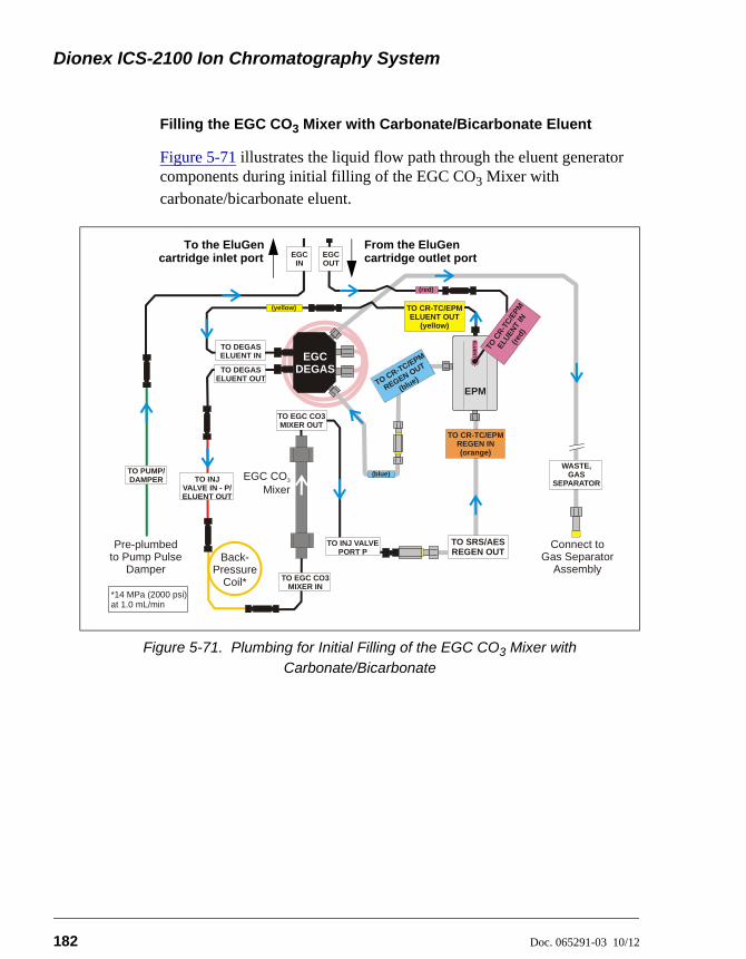
Dionex ICS-2100 Ion Chromatography System
182 Doc. 065291-03 10/12
Filling the EGC CO3 Mixer with Carbonate/Bicarbonate Eluent
Figure 5-71 illustrates the liquid flow path through the eluent generator components during initial filling of the EGC CO3 Mixer with carbonate/bicarbonate eluent.
Figure 5-71. Plumbing for Initial Filling of the EGC CO3 Mixer with Carbonate/Bicarbonate
EGC IN
TO DEGASELUENT OUT
WASTE, GAS
SEPARATORTO INJ VALVE IN - P/ELUENT OUT
TO DEGASELUENT IN EGC
DEGAS
Connect toGas Separator
Assembly
Pre-plumbed Pump Pulse
Damperto
EGC CO Mixer
3
TO CR-TC/EPM REGEN IN (orange)
TO PUMP/DAMPER
TO CR-TC/EPM ELUENT OUT
(yellow)
TO CR-TC/EPM
REGEN OUT
(blue)
EPM
EL
UE
NT
IN
TO C
R-T
C/E
PM
ELU
ENT
IN(r
ed)
EGC OUT
(yellow)
(blue)
(red)
TO EGC CO3 MIXER IN
TO INJ VALVE PORT P
TO EGC CO3 MIXER OUT
TO SRS/AESREGEN OUTBack-
PressureCoil*
*
14 MPa (2000 psi) at 1.0 mL/min
From the EluGencartridge outlet port
To the EluGencartridge inlet port
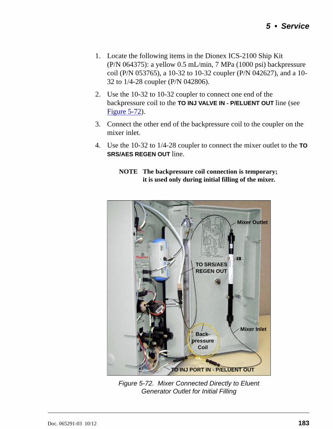
5 • Service
Doc. 065291-03 10/12 183
1. Locate the following items in the Dionex ICS-2100 Ship Kit (P/N 064375): a yellow 0.5 mL/min, 7 MPa (1000 psi) backpressure coil (P/N 053765), a 10-32 to 10-32 coupler (P/N 042627), and a 10-32 to 1/4-28 coupler (P/N 042806).
2. Use the 10-32 to 10-32 coupler to connect one end of the backpressure coil to the TO INJ VALVE IN - P/ELUENT OUT line (see Figure 5-72).
3. Connect the other end of the backpressure coil to the coupler on the mixer inlet.
4. Use the 10-32 to 1/4-28 coupler to connect the mixer outlet to the TO
SRS/AES REGEN OUT line.
NOTE The backpressure coil connection is temporary;it is used only during initial filling of the mixer.
Figure 5-72. Mixer Connected Directly to Eluent Generator Outlet for Initial Filling
Back-pressure
Coil
TO INJ PORT IN - P/ELUENT OUT
Mixer Inlet
Mixer Outlet
TO SRS/AES REGEN OUT
Dionex ICS-2100 Ion Chromatography System
184 Doc. 065291-03 10/12
5. Verify that the suppressor and the auxiliary electrolytic device (if installed) are off.
6. Verify that the Automatically turn on with pump option is not selected on the touch screen SUPPRESSOR page (see Section B.9). Disabling this option lets you turn on the pump, without automatically turning on the suppressor.
7. Set the pump flow rate to the rate required for the application.
8. Turn on the pump.
9. Verify that the system backpressure is between 14 and 16 MPa (2000 and 2300 psi). If necessary, adjust the pressure by adding or removing backpressure tubing.
10. Set the EGC-1 and EGC-2 concentrations to the values required for your application. For example, for a 3.5 mM K2CO3/1.0 mM KHCO3 mixture, set the EGC-1 concentration to 3.5 mM and the EGC-2 concentration to 1.0 mM.
11. Turn on the EGC-1 and EGC-2 currents.
12. Run at the selected settings until the mixer is filled with the eluent mixture. At a flow rate of 1 mL/min it will take about 45 minutes to fill the 4-mm mixer and about 15 minutes to fill the 2-mm mixer.
NOTE The void volume of the 4-mm mixer is about16 mL. The void volume of the 2-mm mixer isabout 5 mL.
13. Turn off the EGC-1 and EGC-2 currents.
14. Turn off the pump.
15. Remove the backpressure coil from the TO INJ VALVE IN - P/ELUENT
OUT line and the mixer inlet. Reconnect the two lines.
16. Disconnect the mixer outlet from the TO SRS/AES REGEN OUT line and remove the 10-32 to 1/4-28 coupler.
To avoid damaging the suppressor and auxiliary electrolytic device (ifinstalled), always turn them off before filling the mixer. The pump flowis on during filling; however, no flow reaches the suppressor orauxiliary electrolytic device.

5 • Service
Doc. 065291-03 10/12 185
17. Reconnect the TO SRS/AES REGEN OUT line to the suppressor REGEN
OUT port.
18. Reconnect the mixer outlet line to port P (2) on the injection valve.
5.23 Replacing the EGC Holder and Degas Assembly
5.23.1 Disconnecting and Removing the Dionex EluGen Cartridge
1. Turn off the power to the Dionex ICS-2100.
2. Disconnect the following EGC holder liquid lines:
• Disconnect the line labeled TO INJ VALVE IN - P/ELUENT OUT from either port P (2) on the injection valve, or if an EGC CO3 Mixer inlet is installed, from the mixer inlet.
• If a CR-TC is installed, disconnect the line labeled TO SRS/AES
REGEN OUT from the REGEN OUT port on the suppressor.
• Disconnect the line labeled TO PUMP/DAMPER from the pump damper.
• Disconnect the line labeled WASTE-GAS SEPARATOR from the gas separator waste tube assembly installed on the waste container.
3. Disconnect the Dionex EluGen cartridge cable, and the CR-TC or EPM cable (if installed) from their respective connectors on the Dionex ICS-2100 top cover.
The Dionex EluGen cartridge contains one of the following: acorrosive base (KOH, LiOH, or NaOH), or a corrosive acid (MSA). Wearprotective eyewear and gloves when handling the cartridge.
La cartouche d'Dionex EluGen contient un de ce qui suit: une basecorrosive (KOH, LiOH, ou NaOH), ou un acide corrosif (MSA). Porterdes lunettes et des gants protectives en manipulant la cartouche.
Die Dionex EluGen-Kartusche enthält eine korrosive Base (KOH, LiOHoder NaOH), oder eine korrosive Säure (MSA). Tragen Sie daher beimUmgang mit der Kartusche eine Schutzbrille und Handschuhe.
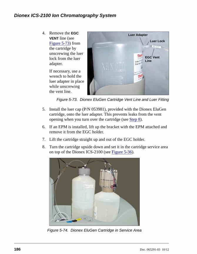
Dionex ICS-2100 Ion Chromatography System
186 Doc. 065291-03 10/12
4. Remove the EGC
VENT line (see Figure 5-73) from the cartridge by unscrewing the luer lock from the luer adapter.
If necessary, use a wrench to hold the luer adapter in place while unscrewing the vent line.
Figure 5-73. Dionex EluGen Cartridge Vent Line and Luer Fitting
5. Install the luer cap (P/N 053981), provided with the Dionex EluGen cartridge, onto the luer adapter. This prevents leaks from the vent opening when you turn over the cartridge (see Step 8).
6. If an EPM is installed, lift up the bracket with the EPM attached and remove it from the EGC holder.
7. Lift the cartridge straight up and out of the EGC holder.
8. Turn the cartridge upside down and set it in the cartridge service area on top of the Dionex ICS-2100 (see Figure 5-36).
Figure 5-74. Dionex EluGen Cartridge in Service Area
Luer Lock
Luer Adapter
EGC VentLine
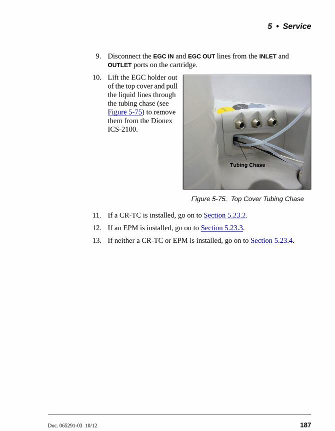
5 • Service
Doc. 065291-03 10/12 187
9. Disconnect the EGC IN and EGC OUT lines from the INLET and OUTLET ports on the cartridge.
10. Lift the EGC holder out of the top cover and pull the liquid lines through the tubing chase (see Figure 5-75) to remove them from the Dionex ICS-2100.
Figure 5-75. Top Cover Tubing Chase
11. If a CR-TC is installed, go on to Section 5.23.2.
12. If an EPM is installed, go on to Section 5.23.3.
13. If neither a CR-TC or EPM is installed, go on to Section 5.23.4.
Tubing Chase
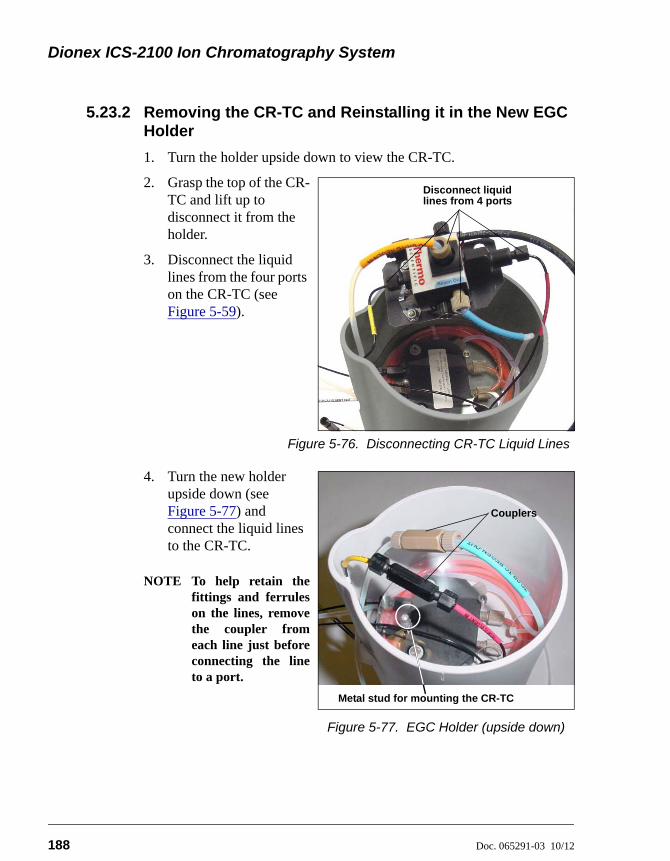
Dionex ICS-2100 Ion Chromatography System
188 Doc. 065291-03 10/12
5.23.2 Removing the CR-TC and Reinstalling it in the New EGC Holder
1. Turn the holder upside down to view the CR-TC.
2. Grasp the top of the CR-TC and lift up to disconnect it from the holder.
3. Disconnect the liquid lines from the four ports on the CR-TC (see Figure 5-59).
Figure 5-76. Disconnecting CR-TC Liquid Lines
4. Turn the new holder upside down (see Figure 5-77) and connect the liquid lines to the CR-TC.
NOTE To help retain thefittings and ferruleson the lines, removethe coupler fromeach line just beforeconnecting the lineto a port.
Figure 5-77. EGC Holder (upside down)
Disconnect liquid lines from 4 ports
Couplers
Metal stud for mounting the CR-TC
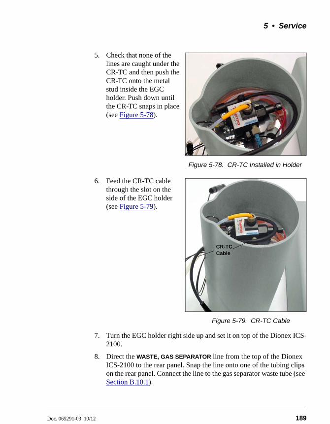
5 • Service
Doc. 065291-03 10/12 189
5. Check that none of the lines are caught under the CR-TC and then push the CR-TC onto the metal stud inside the EGC holder. Push down until the CR-TC snaps in place (see Figure 5-78).
Figure 5-78. CR-TC Installed in Holder
6. Feed the CR-TC cable through the slot on the side of the EGC holder (see Figure 5-79).
Figure 5-79. CR-TC Cable
7. Turn the EGC holder right side up and set it on top of the Dionex ICS-2100.
8. Direct the WASTE, GAS SEPARATOR line from the top of the Dionex ICS-2100 to the rear panel. Snap the line onto one of the tubing clips on the rear panel. Connect the line to the gas separator waste tube (see Section B.10.1).
CR-TC Cable
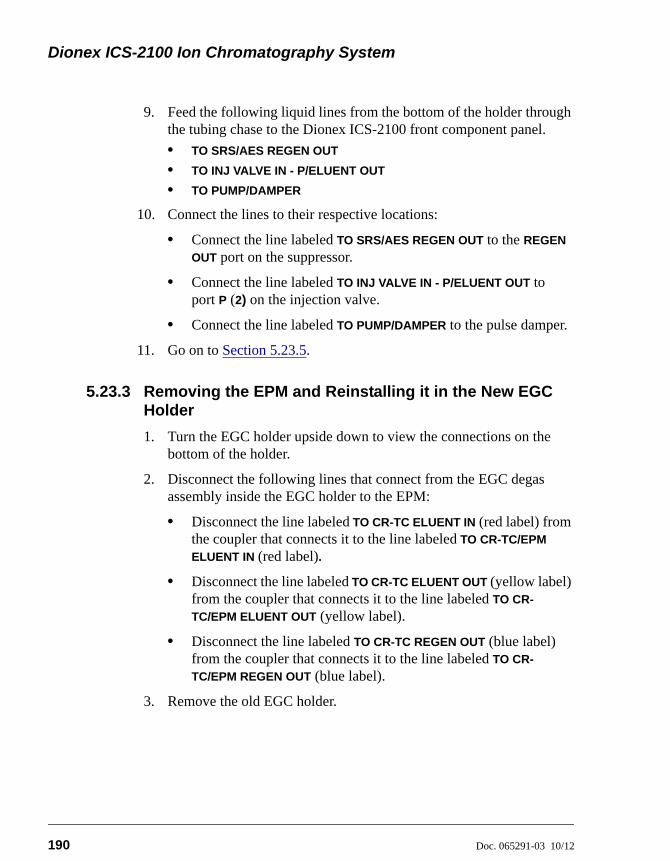
Dionex ICS-2100 Ion Chromatography System
190 Doc. 065291-03 10/12
9. Feed the following liquid lines from the bottom of the holder through the tubing chase to the Dionex ICS-2100 front component panel.
• TO SRS/AES REGEN OUT
• TO INJ VALVE IN - P/ELUENT OUT
• TO PUMP/DAMPER
10. Connect the lines to their respective locations:
• Connect the line labeled TO SRS/AES REGEN OUT to the REGEN
OUT port on the suppressor.
• Connect the line labeled TO INJ VALVE IN - P/ELUENT OUT to port P (2) on the injection valve.
• Connect the line labeled TO PUMP/DAMPER to the pulse damper.
11. Go on to Section 5.23.5.
5.23.3 Removing the EPM and Reinstalling it in the New EGC Holder
1. Turn the EGC holder upside down to view the connections on the bottom of the holder.
2. Disconnect the following lines that connect from the EGC degas assembly inside the EGC holder to the EPM:
• Disconnect the line labeled TO CR-TC ELUENT IN (red label) from the coupler that connects it to the line labeled TO CR-TC/EPM
ELUENT IN (red label).
• Disconnect the line labeled TO CR-TC ELUENT OUT (yellow label) from the coupler that connects it to the line labeled TO CR-
TC/EPM ELUENT OUT (yellow label).
• Disconnect the line labeled TO CR-TC REGEN OUT (blue label) from the coupler that connects it to the line labeled TO CR-
TC/EPM REGEN OUT (blue label).
3. Remove the old EGC holder.
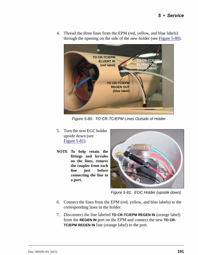
5 • Service
Doc. 065291-03 10/12 191
4. Thread the three lines from the EPM (red, yellow, and blue labels) through the opening on the side of the new holder (see Figure 5-80).
5. Turn the new EGC holder upside down (see Figure 5-81).
NOTE To help retain thefittings and ferruleson the lines, removethe coupler from eachline just beforeconnecting the line toa port.
Figure 5-81. EGC Holder (upside down)
6. Connect the lines from the EPM (red, yellow, and blue labels) to the corresponding lines in the holder.
7. Disconnect the line labeled TO CR-TC/EPM REGEN IN (orange label) from the REGEN IN port on the EPM and connect the new TO CR-
TC/EPM REGEN IN line (orange label) to the port.
Figure 5-80. TO CR-TC/EPM Lines Outside of Holder
TO CR-TC/EPM ELUENT OUT (yellow label)
TO CR-TC/EPMELUENT IN(red label)
TO CR-TC/EPMREGEN OUT
(blue label)
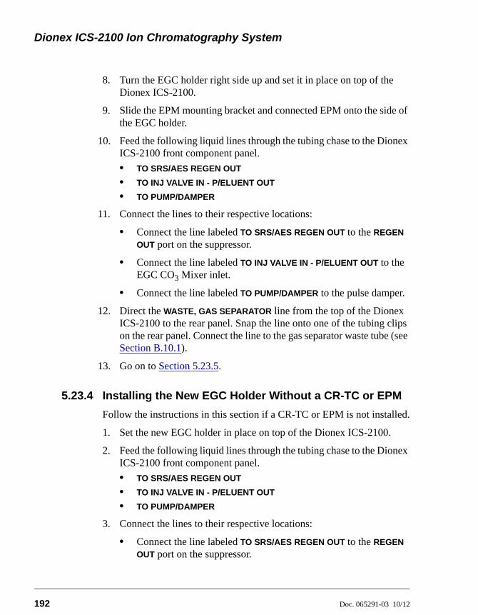
Dionex ICS-2100 Ion Chromatography System
192 Doc. 065291-03 10/12
8. Turn the EGC holder right side up and set it in place on top of the Dionex ICS-2100.
9. Slide the EPM mounting bracket and connected EPM onto the side of the EGC holder.
10. Feed the following liquid lines through the tubing chase to the Dionex ICS-2100 front component panel.
• TO SRS/AES REGEN OUT
• TO INJ VALVE IN - P/ELUENT OUT
• TO PUMP/DAMPER
11. Connect the lines to their respective locations:
• Connect the line labeled TO SRS/AES REGEN OUT to the REGEN
OUT port on the suppressor.
• Connect the line labeled TO INJ VALVE IN - P/ELUENT OUT to the EGC CO3 Mixer inlet.
• Connect the line labeled TO PUMP/DAMPER to the pulse damper.
12. Direct the WASTE, GAS SEPARATOR line from the top of the Dionex ICS-2100 to the rear panel. Snap the line onto one of the tubing clips on the rear panel. Connect the line to the gas separator waste tube (see Section B.10.1).
13. Go on to Section 5.23.5.
5.23.4 Installing the New EGC Holder Without a CR-TC or EPM
Follow the instructions in this section if a CR-TC or EPM is not installed.
1. Set the new EGC holder in place on top of the Dionex ICS-2100.
2. Feed the following liquid lines through the tubing chase to the Dionex ICS-2100 front component panel.
• TO SRS/AES REGEN OUT
• TO INJ VALVE IN - P/ELUENT OUT
• TO PUMP/DAMPER
3. Connect the lines to their respective locations:
• Connect the line labeled TO SRS/AES REGEN OUT to the REGEN
OUT port on the suppressor.
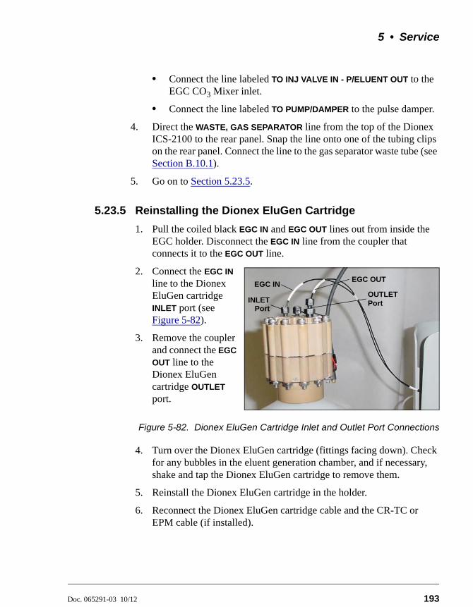
5 • Service
Doc. 065291-03 10/12 193
• Connect the line labeled TO INJ VALVE IN - P/ELUENT OUT to the EGC CO3 Mixer inlet.
• Connect the line labeled TO PUMP/DAMPER to the pulse damper.
4. Direct the WASTE, GAS SEPARATOR line from the top of the Dionex ICS-2100 to the rear panel. Snap the line onto one of the tubing clips on the rear panel. Connect the line to the gas separator waste tube (see Section B.10.1).
5. Go on to Section 5.23.5.
5.23.5 Reinstalling the Dionex EluGen Cartridge
1. Pull the coiled black EGC IN and EGC OUT lines out from inside the EGC holder. Disconnect the EGC IN line from the coupler that connects it to the EGC OUT line.
2. Connect the EGC IN
line to the Dionex EluGen cartridge INLET port (see Figure 5-82).
3. Remove the coupler and connect the EGC
OUT line to the Dionex EluGen cartridge OUTLET port.
Figure 5-82. Dionex EluGen Cartridge Inlet and Outlet Port Connections
4. Turn over the Dionex EluGen cartridge (fittings facing down). Check for any bubbles in the eluent generation chamber, and if necessary, shake and tap the Dionex EluGen cartridge to remove them.
5. Reinstall the Dionex EluGen cartridge in the holder.
6. Reconnect the Dionex EluGen cartridge cable and the CR-TC or EPM cable (if installed).
EGC OUT
OUTLETPort
EGC IN
INLETPort
Dionex ICS-2100 Ion Chromatography System
194 Doc. 065291-03 10/12
Remove the cap from the luer adapter on the Dionex EluGen cartridge
vent opening and re-connect the EGC VENT line.
Doc. 065291-03 10/12 195
A • Specifications
A.1 Electrical
A.2 Physical
Main Power 100 to 240 Vac, 50 to 60 Hz (Auto-sensing power supply; no manual voltage or frequency adjustment required)
Fuses Two 3.15 amp fast-blow IEC 127 fuses (P/N 954745)
Dimensions(Without
reservoir orEluGen
cartridge)
Height: 56.1 cm (22.1 in)Width: 22.4 cm (8.8 in)Depth: 53.3 cm (21.0 in)
Weight 24.5 kg (54 lb)
Decibel Level <52 dBA
Control Modes Full control through front panel and Chromeleon software; alternative control through TTL or relay closure (two relay outputs, two TTL outputs, four programmable inputs)
USBCommunication
Protocol
One USB input; one built-in USB hub with two outputs
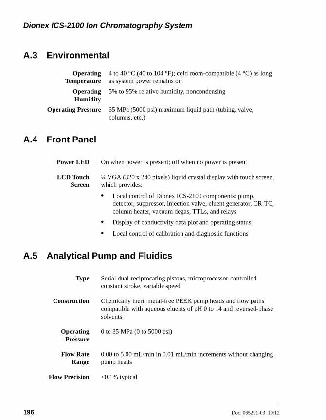
Dionex ICS-2100 Ion Chromatography System
196 Doc. 065291-03 10/12
A.3 Environmental
A.4 Front Panel
A.5 Analytical Pump and Fluidics
OperatingTemperature
4 to 40 °C (40 to 104 °F); cold room-compatible (4 °C) as long as system power remains on
OperatingHumidity
5% to 95% relative humidity, noncondensing
Operating Pressure 35 MPa (5000 psi) maximum liquid path (tubing, valve, columns, etc.)
Power LED On when power is present; off when no power is present
LCD TouchScreen
¼ VGA (320 x 240 pixels) liquid crystal display with touch screen, which provides:
• Local control of Dionex ICS-2100 components: pump, detector, suppressor, injection valve, eluent generator, CR-TC, column heater, vacuum degas, TTLs, and relays
• Display of conductivity data plot and operating status
• Local control of calibration and diagnostic functions
Type Serial dual-reciprocating pistons, microprocessor-controlled constant stroke, variable speed
Construction Chemically inert, metal-free PEEK pump heads and flow paths compatible with aqueous eluents of pH 0 to 14 and reversed-phase solvents
OperatingPressure
0 to 35 MPa (0 to 5000 psi)
Flow RateRange
0.00 to 5.00 mL/min in 0.01 mL/min increments without changing pump heads
Flow Precision <0.1% typical
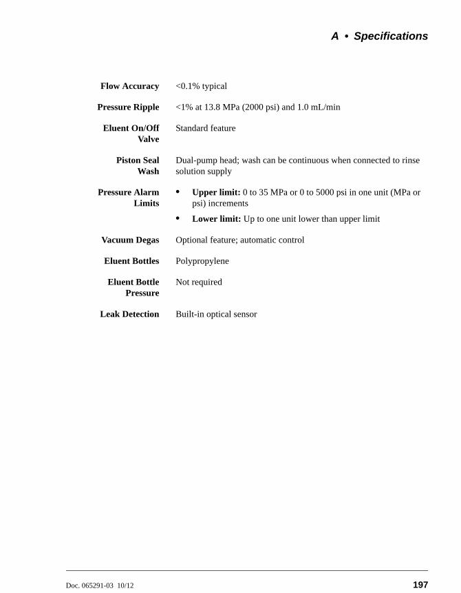
A • Specifications
Doc. 065291-03 10/12 197
Flow Accuracy <0.1% typical
Pressure Ripple <1% at 13.8 MPa (2000 psi) and 1.0 mL/min
Eluent On/OffValve
Standard feature
Piston SealWash
Dual-pump head; wash can be continuous when connected to rinse solution supply
Pressure AlarmLimits
• Upper limit: 0 to 35 MPa or 0 to 5000 psi in one unit (MPa or psi) increments
• Lower limit: Up to one unit lower than upper limit
Vacuum Degas Optional feature; automatic control
Eluent Bottles Polypropylene
Eluent BottlePressure
Not required
Leak Detection Built-in optical sensor
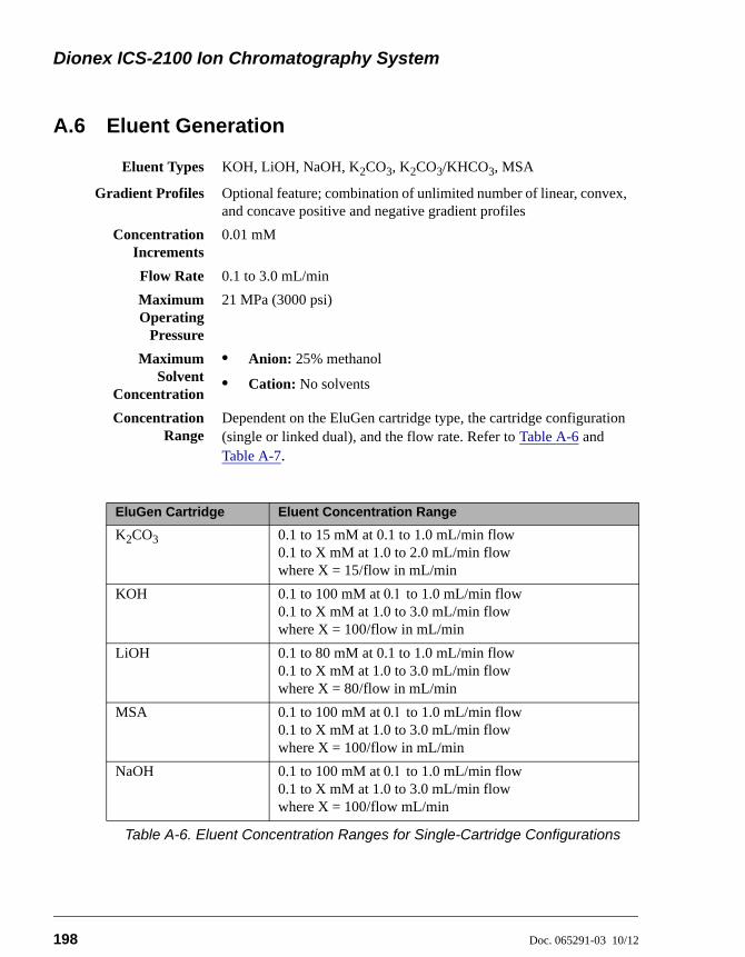
Dionex ICS-2100 Ion Chromatography System
198 Doc. 065291-03 10/12
A.6 Eluent Generation
Eluent Types KOH, LiOH, NaOH, K2CO3, K2CO3/KHCO3, MSA
Gradient Profiles Optional feature; combination of unlimited number of linear, convex, and concave positive and negative gradient profiles
ConcentrationIncrements
0.01 mM
Flow Rate 0.1 to 3.0 mL/min
MaximumOperating
Pressure
21 MPa (3000 psi)
MaximumSolvent
Concentration
• Anion: 25% methanol
• Cation: No solvents
ConcentrationRange
Dependent on the EluGen cartridge type, the cartridge configuration (single or linked dual), and the flow rate. Refer to Table A-6 and Table A-7.
EluGen Cartridge Eluent Concentration Range
K2CO3 0.1 to 15 mM at 0.1 to 1.0 mL/min flow0.1 to X mM at 1.0 to 2.0 mL/min flowwhere X = 15/flow in mL/min
KOH 0.1 to 100 mM at to 1.0 mL/min flow0.1 to X mM at 1.0 to 3.0 mL/min flowwhere X = 100/flow in mL/min
LiOH 0.1 to 80 mM at 0.1 to 1.0 mL/min flow0.1 to X mM at 1.0 to 3.0 mL/min flowwhere X = 80/flow in mL/min
MSA 0.1 to 100 mM at to 1.0 mL/min flow0.1 to X mM at 1.0 to 3.0 mL/min flowwhere X = 100/flow in mL/min
NaOH 0.1 to 100 mM at to 1.0 mL/min flow0.1 to X mM at 1.0 to 3.0 mL/min flowwhere X = 100/flow mL/min
Table A-6. Eluent Concentration Ranges for Single-Cartridge Configurations
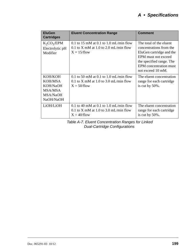
A • Specifications
Doc. 065291-03 10/12 199
EluGen Cartridges
Eluent Concentration Range Comment
K2CO3/EPM
Electrolytic pH Modifier
0.1 to 15 mM at 0.1 to 1.0 mL/min flow 0.1 to X mM at 1.0 to 2.0 mL/min flowX = 15/flow
The total of the eluent concentrations from the EluGen cartridge and the EPM must not exceed the specified range. The EPM concentration must not exceed 10 mM.
KOH/KOHKOH/MSAKOH/NaOHMSA/MSAMSA/NaOHNaOH/NaOH
0.1 to 50 mM at 0.1 to 1.0 mL/min flow0.1 to X mM at 1.0 to 3.0 mL/min flowX = 50/flow
The eluent concentration range for each cartridge is cut by 50%.
LiOH/LiOH 0.1 to 40 mM at 0.1 to 1.0 mL/min flow0.1 to X mM at 1.0 to 3.0 mL/min flowX = 40/flow
The eluent concentration range for each cartridge is cut by 50%.
Table A-7. Eluent Concentration Ranges for Linked Dual-Cartridge Configurations
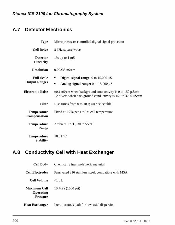
Dionex ICS-2100 Ion Chromatography System
200 Doc. 065291-03 10/12
A.7 Detector Electronics
A.8 Conductivity Cell with Heat Exchanger
Type Microprocessor-controlled digital signal processor
Cell Drive 8 kHz square wave
DetectorLinearity
1% up to 1 mS
Resolution 0.00238 nS/cm
Full-ScaleOutput Ranges
• Digital signal range: 0 to 15,000 S
• Analog signal range: 0 to 15,000 S
Electronic Noise ±0.1 nS/cm when background conductivity is 0 to 150 S/cm±2 nS/cm when background conductivity is 151 to 3200 S/cm
Filter Rise times from 0 to 10 s; user-selectable
TemperatureCompensation
Fixed at 1.7% per 1 °C at cell temperature
TemperatureRange
Ambient +7 °C; 30 to 55 °C
TemperatureStability
<0.01 °C
Cell Body Chemically inert polymeric material
Cell Electrodes Passivated 316 stainless steel; compatible with MSA
Cell Volume <1 L
Maximum CellOperating
Pressure
10 MPa (1500 psi)
Heat Exchanger Inert, tortuous path for low axial dispersion
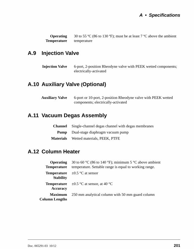
A • Specifications
Doc. 065291-03 10/12 201
A.9 Injection Valve
A.10 Auxiliary Valve (Optional)
A.11 Vacuum Degas Assembly
A.12 Column Heater
OperatingTemperature
30 to 55 ºC (86 to 130 ºF); must be at least 7 ºC above the ambient temperature
Injection Valve 6-port, 2-position Rheodyne valve with PEEK wetted components; electrically-activated
Auxiliary Valve 6-port or 10-port, 2-position Rheodyne valve with PEEK wetted components; electrically-activated
Channel Single-channel degas channel with degas membranes
Pump Dual-stage diaphragm vacuum pump
Materials Wetted materials, PEEK, PTFE
OperatingTemperature
30 to 60 °C (86 to 140 °F); minimum 5 °C above ambient temperature. Settable range is equal to working range.
TemperatureStability
±0.5 °C at sensor
TemperatureAccuracy
±0.5 °C at sensor, at 40 °C
MaximumColumn Lengths
250 mm analytical column with 50 mm guard column
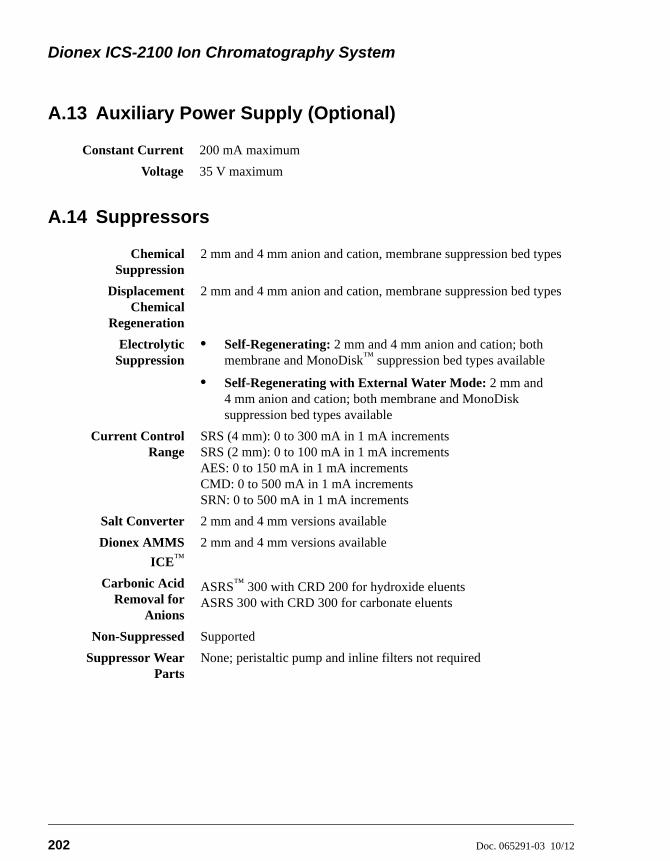
Dionex ICS-2100 Ion Chromatography System
202 Doc. 065291-03 10/12
A.13 Auxiliary Power Supply (Optional)
A.14 Suppressors
Constant Current 200 mA maximum
Voltage 35 V maximum
ChemicalSuppression
2 mm and 4 mm anion and cation, membrane suppression bed types
DisplacementChemical
Regeneration
2 mm and 4 mm anion and cation, membrane suppression bed types
ElectrolyticSuppression
• Self-Regenerating: 2 mm and 4 mm anion and cation; both membrane and MonoDisk™ suppression bed types available
• Self-Regenerating with External Water Mode: 2 mm and 4 mm anion and cation; both membrane and MonoDisk suppression bed types available
Current ControlRange
SRS (4 mm): 0 to 300 mA in 1 mA incrementsSRS (2 mm): 0 to 100 mA in 1 mA incrementsAES: 0 to 150 mA in 1 mA incrementsCMD: 0 to 500 mA in 1 mA incrementsSRN: 0 to 500 mA in 1 mA increments
Salt Converter 2 mm and 4 mm versions available
Dionex AMMS
ICE™2 mm and 4 mm versions available
Carbonic AcidRemoval for
Anions
ASRS™ 300 with CRD 200 for hydroxide eluentsASRS 300 with CRD 300 for carbonate eluents
Non-Suppressed Supported
Suppressor WearParts
None; peristaltic pump and inline filters not required
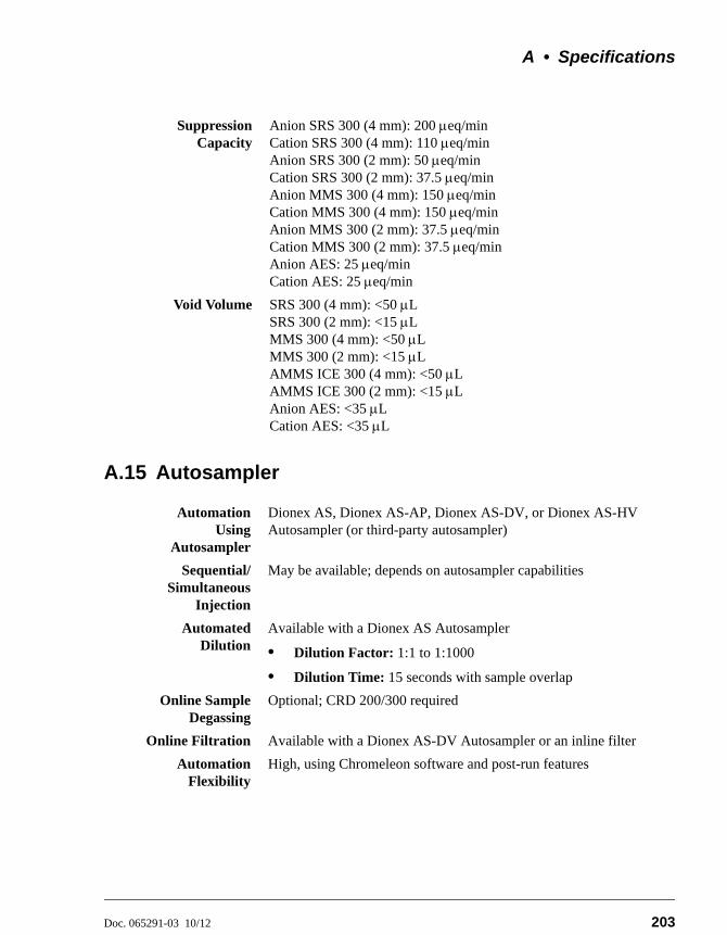
A • Specifications
Doc. 065291-03 10/12 203
A.15 Autosampler
SuppressionCapacity
Anion SRS 300 (4 mm): 200 eq/minCation SRS 300 (4 mm): 110 eq/minAnion SRS 300 (2 mm): 50 eq/minCation SRS 300 (2 mm): 37.5 eq/minAnion MMS 300 (4 mm): 150 eq/minCation MMS 300 (4 mm): 150 eq/minAnion MMS 300 (2 mm): 37.5 eq/minCation MMS 300 (2 mm): 37.5 eq/minAnion AES: 25 eq/minCation AES: 25 eq/min
Void Volume SRS 300 (4 mm): <50 LSRS 300 (2 mm): <15 LMMS 300 (4 mm): <50 LMMS 300 (2 mm): <15 LAMMS ICE 300 (4 mm): <50 LAMMS ICE 300 (2 mm): <15 LAnion AES: <35 LCation AES: <35 L
AutomationUsing
Autosampler
Dionex AS, Dionex AS-AP, Dionex AS-DV, or Dionex AS-HV Autosampler (or third-party autosampler)
Sequential/Simultaneous
Injection
May be available; depends on autosampler capabilities
AutomatedDilution
Available with a Dionex AS Autosampler
• Dilution Factor: 1:1 to 1:1000
• Dilution Time: 15 seconds with sample overlap
Online SampleDegassing
Optional; CRD 200/300 required
Online Filtration Available with a Dionex AS-DV Autosampler or an inline filter
AutomationFlexibility
High, using Chromeleon software and post-run features
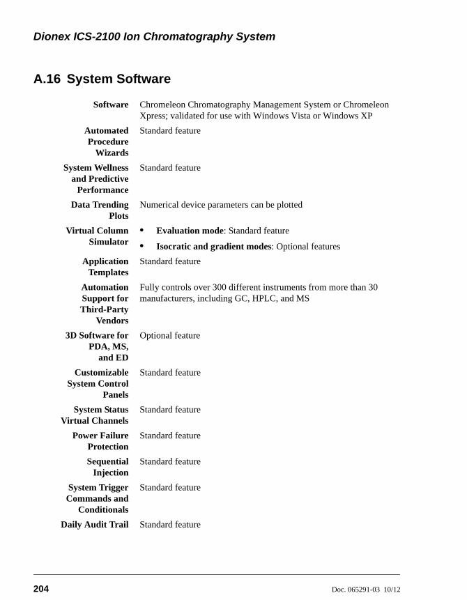
Dionex ICS-2100 Ion Chromatography System
204 Doc. 065291-03 10/12
A.16 System Software
Software Chromeleon Chromatography Management System or Chromeleon Xpress; validated for use with Windows Vista or Windows XP
AutomatedProcedure
Wizards
Standard feature
System Wellnessand Predictive
Performance
Standard feature
Data TrendingPlots
Numerical device parameters can be plotted
Virtual ColumnSimulator
• Evaluation mode: Standard feature
• Isocratic and gradient modes: Optional features
ApplicationTemplates
Standard feature
AutomationSupport forThird-Party
Vendors
Fully controls over 300 different instruments from more than 30 manufacturers, including GC, HPLC, and MS
3D Software forPDA, MS,
and ED
Optional feature
CustomizableSystem Control
Panels
Standard feature
System StatusVirtual Channels
Standard feature
Power FailureProtection
Standard feature
SequentialInjection
Standard feature
System TriggerCommands and
Conditionals
Standard feature
Daily Audit Trail Standard feature
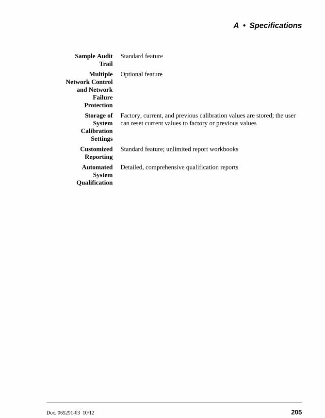
A • Specifications
Doc. 065291-03 10/12 205
Sample AuditTrail
Standard feature
MultipleNetwork Control
and NetworkFailure
Protection
Optional feature
Storage ofSystem
CalibrationSettings
Factory, current, and previous calibration values are stored; the user can reset current values to factory or previous values
CustomizedReporting
Standard feature; unlimited report workbooks
AutomatedSystem
Qualification
Detailed, comprehensive qualification reports

Dionex ICS-2100 Ion Chromatography System
206 Doc. 065291-03 10/12
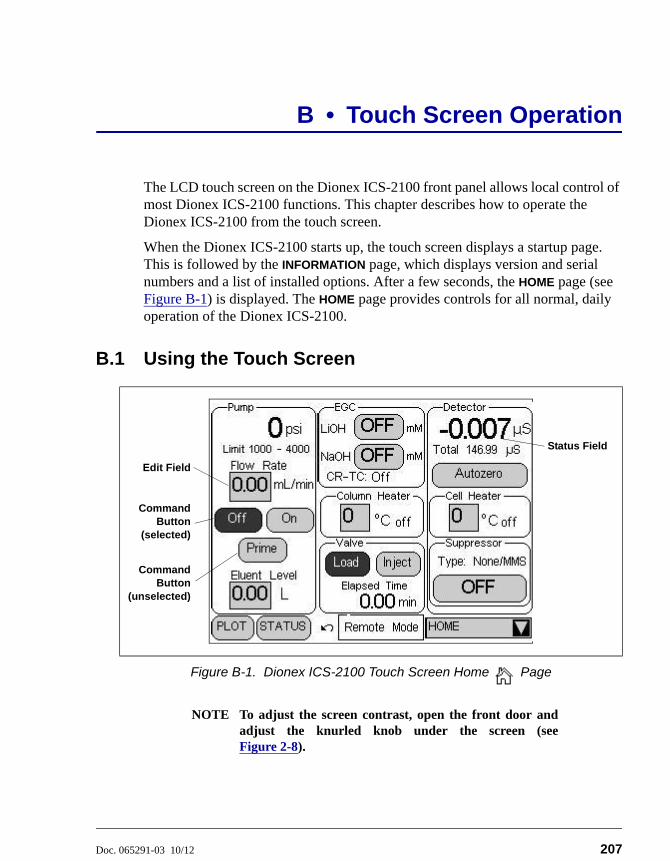
Doc. 065291-03 10/12 207
B • Touch Screen Operation
The LCD touch screen on the Dionex ICS-2100 front panel allows local control of most Dionex ICS-2100 functions. This chapter describes how to operate the Dionex ICS-2100 from the touch screen.
When the Dionex ICS-2100 starts up, the touch screen displays a startup page. This is followed by the INFORMATION page, which displays version and serial numbers and a list of installed options. After a few seconds, the HOME page (see Figure B-1) is displayed. The HOME page provides controls for all normal, daily operation of the Dionex ICS-2100.
B.1 Using the Touch Screen
NOTE To adjust the screen contrast, open the front door andadjust the knurled knob under the screen (seeFigure 2-8).
Figure B-1. Dionex ICS-2100 Touch Screen Home Page
Edit Field
CommandButton
(selected)
CommandButton
(unselected)
Status Field
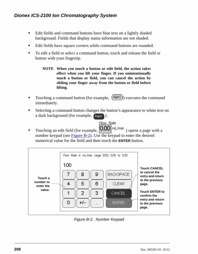
Dionex ICS-2100 Ion Chromatography System
208 Doc. 065291-03 10/12
• Edit fields and command buttons have blue text on a lightly shaded background. Fields that display status information are not shaded.
• Edit fields have square corners while command buttons are rounded.
• To edit a field or select a command button, touch and release the field or button with your fingertip.
NOTE When you touch a button or edit field, the action takeseffect when you lift your finger. If you unintentionallytouch a button or field, you can cancel the action bysliding your finger away from the button or field beforelifting.
• Touching a command button (for example, ) executes the command immediately.
• Selecting a command button changes the button’s appearance to white text on a dark background (for example, ).
• Touching an edit field (for example, ) opens a page with a number keypad (see Figure B-2). Use the keypad to enter the desired numerical value for the field and then touch the ENTER button.
Figure B-2. Number Keypad
Touch anumber to
enter thevalue.
Touch ENTER to confirm the entry and return to the previous page.
Touch CANCEL to cancel the entry and return to the previous page.
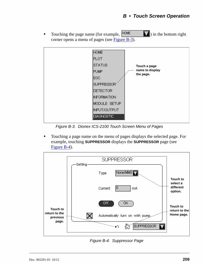
B • Touch Screen Operation
Doc. 065291-03 10/12 209
• Touching the page name (for example, ) in the bottom right corner opens a menu of pages (see Figure B-3).
Figure B-3. Dionex ICS-2100 Touch Screen Menu of Pages
• Touching a page name on the menu of pages displays the selected page. For example, touching SUPPRESSOR displays the SUPPRESSOR page (see Figure B-4).
Figure B-4. Suppressor Page
Touch a page name to display the page.
Touch to return to the Home page.
Touch to select a different option.
Touch toreturn to the
previouspage.
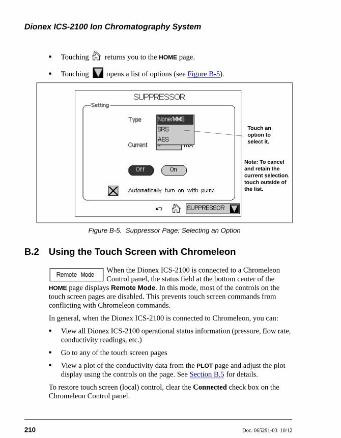
Dionex ICS-2100 Ion Chromatography System
210 Doc. 065291-03 10/12
• Touching returns you to the HOME page.
• Touching opens a list of options (see Figure B-5).
B.2 Using the Touch Screen with Chromeleon
When the Dionex ICS-2100 is connected to a Chromeleon Control panel, the status field at the bottom center of the
HOME page displays Remote Mode. In this mode, most of the controls on the touch screen pages are disabled. This prevents touch screen commands from conflicting with Chromeleon commands.
In general, when the Dionex ICS-2100 is connected to Chromeleon, you can:
• View all Dionex ICS-2100 operational status information (pressure, flow rate, conductivity readings, etc.)
• Go to any of the touch screen pages
• View a plot of the conductivity data from the PLOT page and adjust the plot display using the controls on the page. See Section B.5 for details.
To restore touch screen (local) control, clear the Connected check box on the Chromeleon Control panel.
Figure B-5. Suppressor Page: Selecting an Option
Touch an option to select it.
Note: To cancel and retain the current selection,touch outside of the list.
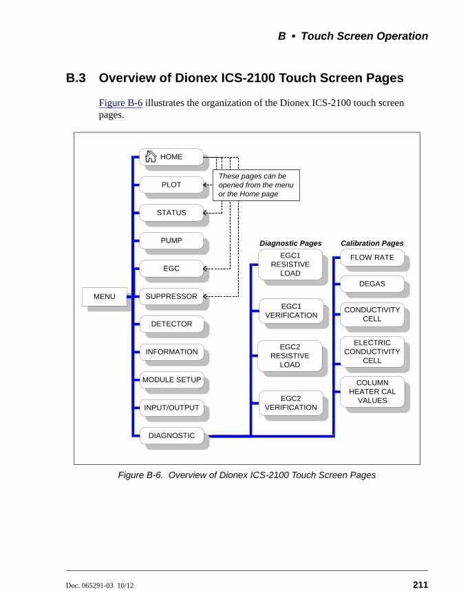
B • Touch Screen Operation
Doc. 065291-03 10/12 211
B.3 Overview of Dionex ICS-2100 Touch Screen Pages
Figure B-6 illustrates the organization of the Dionex ICS-2100 touch screen pages.
Figure B-6. Overview of Dionex ICS-2100 Touch Screen Pages
FLOW RATE
MENU
Calibration PagesDiagnostic Pages
DIAGNOSTIC
PUMP
DETECTOR
HOME
SUPPRESSOR
EGC
STATUS
PLOT
INFORMATION
INPUT/OUTPUT
MODULE SETUP
These pages can beopened from the menuor the Home page
COLUMNHEATER CAL
VALUES
DEGAS
CONDUCTIVITYCELL
EGC1RESISTIVE
LOAD
EGC2RESISTIVE
LOAD
EGC2VERIFICATION
EGC1VERIFICATION
ELECTRICCONDUCTIVITY
CELL
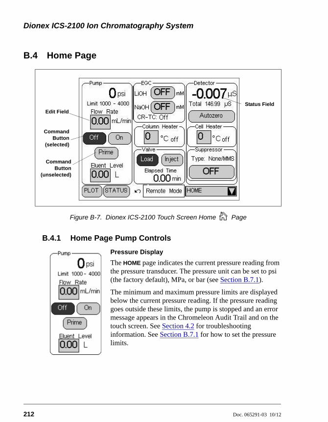
Dionex ICS-2100 Ion Chromatography System
212 Doc. 065291-03 10/12
B.4 Home Page
B.4.1 Home Page Pump Controls
Pressure Display
The HOME page indicates the current pressure reading from the pressure transducer. The pressure unit can be set to psi (the factory default), MPa, or bar (see Section B.7.1).
The minimum and maximum pressure limits are displayed below the current pressure reading. If the pressure reading goes outside these limits, the pump is stopped and an error message appears in the Chromeleon Audit Trail and on the touch screen. See Section 4.2 for troubleshooting information. See Section B.7.1 for how to set the pressure limits.
Figure B-7. Dionex ICS-2100 Touch Screen Home Page
Edit Field
CommandButton
(selected)
CommandButton
(unselected)
Status Field
B • Touch Screen Operation
Doc. 065291-03 10/12 213
Flow Rate
The flow rate can be set to 0.00 (which turns off the pump) and to between 0.05 and 5.00 mL/min. The recommended operating flow rate is between 0.40 and 2.00 mL/min. Refer to the column manual for the flow rate to use with your column and application. Column manuals are included on the Thermo Scientific Reference Library DVD (P/N 053891).
Pump On/Off Control
Touching the On button immediately starts the pump flow at the rate displayed in the Flow Rate field. Touching Off stops the flow.
Prime
The Prime button is reserved for use during the pump head priming procedure. Touching the Prime button displays a confirmation page that reminds you to open the waste valve. Open the valve, and then touch the OK button to begin priming. Or, to exit the page without priming, touch the Cancel button. To stop priming, touch the Off button. During priming, the flow rate is approximately 3 mL/min. See Section B.13 for detailed priming instructions.
Eluent Level
Use this field to monitor the amount of liquid in the eluent reservoir. When you fill the reservoir, enter the amount of liquid in the reservoir. For example, if the reservoir contains 200 mL and you add 1 liter, enter 1.2 liters. Thereafter, the Dionex ICS-2100 determines the eluent usage by monitoring the flow rate and the length of time the pump is on. The Dionex ICS-2100 updates the Eluent Level field as the eluent is depleted. A warning first appears if the level falls below 200 mL. Warnings are repeated at 100 mL and 0 mL.
In order for the eluent level displayed on the screen to be accurate,the level must be entered by the user when the reservoir is filled. TheDionex ICS-2100 does not automatically detect when the reservoir isfilled, nor when it is empty.
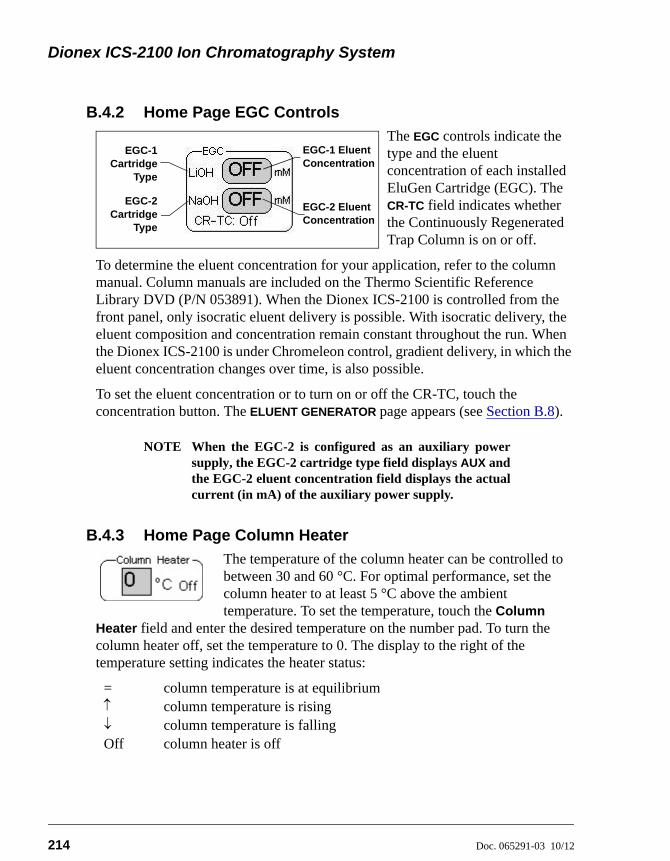
Dionex ICS-2100 Ion Chromatography System
214 Doc. 065291-03 10/12
B.4.2 Home Page EGC Controls
The EGC controls indicate the type and the eluent concentration of each installed EluGen Cartridge (EGC). The CR-TC field indicates whether the Continuously Regenerated Trap Column is on or off.
To determine the eluent concentration for your application, refer to the column manual. Column manuals are included on the Thermo Scientific Reference Library DVD (P/N 053891). When the Dionex ICS-2100 is controlled from the front panel, only isocratic eluent delivery is possible. With isocratic delivery, the eluent composition and concentration remain constant throughout the run. When the Dionex ICS-2100 is under Chromeleon control, gradient delivery, in which the eluent concentration changes over time, is also possible.
To set the eluent concentration or to turn on or off the CR-TC, touch the concentration button. The ELUENT GENERATOR page appears (see Section B.8).
NOTE When the EGC-2 is configured as an auxiliary powersupply, the EGC-2 cartridge type field displays AUX andthe EGC-2 eluent concentration field displays the actualcurrent (in mA) of the auxiliary power supply.
B.4.3 Home Page Column Heater
The temperature of the column heater can be controlled to between 30 and 60 °C. For optimal performance, set the column heater to at least 5 °C above the ambient temperature. To set the temperature, touch the Column
Heater field and enter the desired temperature on the number pad. To turn the column heater off, set the temperature to 0. The display to the right of the temperature setting indicates the heater status:
= column temperature is at equilibrium column temperature is rising column temperature is fallingOff column heater is off
EGC-1 Eluent Concentration
EGC-1Cartridge
Type
EGC-2Cartridge
Type
EGC-2 Eluent Concentration
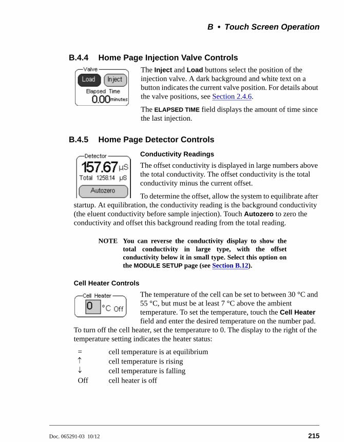
B • Touch Screen Operation
Doc. 065291-03 10/12 215
B.4.4 Home Page Injection Valve Controls
The Inject and Load buttons select the position of the injection valve. A dark background and white text on a button indicates the current valve position. For details about the valve positions, see Section 2.4.6.
The ELAPSED TIME field displays the amount of time since the last injection.
B.4.5 Home Page Detector Controls
Conductivity Readings
The offset conductivity is displayed in large numbers above the total conductivity. The offset conductivity is the total conductivity minus the current offset.
To determine the offset, allow the system to equilibrate after startup. At equilibration, the conductivity reading is the background conductivity (the eluent conductivity before sample injection). Touch Autozero to zero the conductivity and offset this background reading from the total reading.
NOTE You can reverse the conductivity display to show thetotal conductivity in large type, with the offsetconductivity below it in small type. Select this option onthe MODULE SETUP page (see Section B.12).
Cell Heater Controls
The temperature of the cell can be set to between 30 °C and 55 °C, but must be at least 7 °C above the ambient temperature. To set the temperature, touch the Cell Heater field and enter the desired temperature on the number pad.
To turn off the cell heater, set the temperature to 0. The display to the right of the temperature setting indicates the heater status:
= cell temperature is at equilibrium cell temperature is rising cell temperature is fallingOff cell heater is off
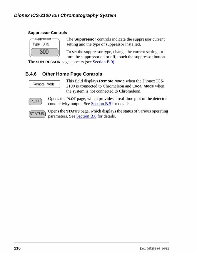
Dionex ICS-2100 Ion Chromatography System
216 Doc. 065291-03 10/12
Suppressor Controls
The Suppressor controls indicate the suppressor current setting and the type of suppressor installed.
To set the suppressor type, change the current setting, or turn the suppressor on or off, touch the suppressor button.
The SUPPRESSOR page appears (see Section B.9).
B.4.6 Other Home Page Controls
This field displays Remote Mode when the Dionex ICS-2100 is connected to Chromeleon and Local Mode when the system is not connected to Chromeleon.
Opens the PLOT page, which provides a real-time plot of the detector conductivity output. See Section B.5 for details.
Opens the STATUS page, which displays the status of various operating parameters. See Section B.6 for details.
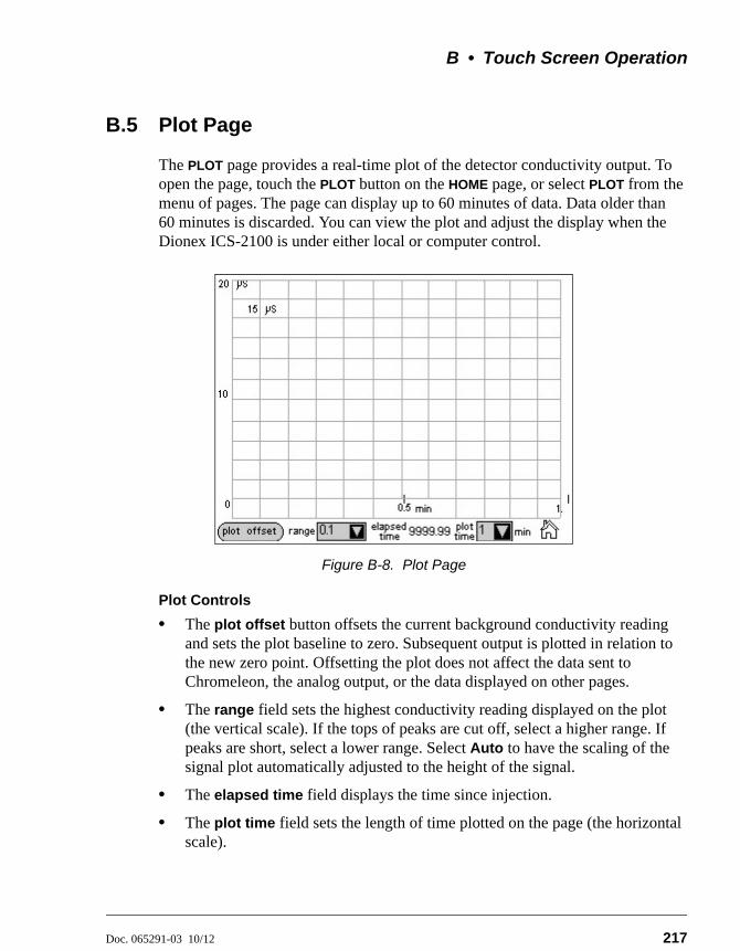
B • Touch Screen Operation
Doc. 065291-03 10/12 217
B.5 Plot Page
The PLOT page provides a real-time plot of the detector conductivity output. To open the page, touch the PLOT button on the HOME page, or select PLOT from the menu of pages. The page can display up to 60 minutes of data. Data older than 60 minutes is discarded. You can view the plot and adjust the display when the Dionex ICS-2100 is under either local or computer control.
Plot Controls
• The plot offset button offsets the current background conductivity reading and sets the plot baseline to zero. Subsequent output is plotted in relation to the new zero point. Offsetting the plot does not affect the data sent to Chromeleon, the analog output, or the data displayed on other pages.
• The range field sets the highest conductivity reading displayed on the plot (the vertical scale). If the tops of peaks are cut off, select a higher range. If peaks are short, select a lower range. Select Auto to have the scaling of the signal plot automatically adjusted to the height of the signal.
• The elapsed time field displays the time since injection.
• The plot time field sets the length of time plotted on the page (the horizontal scale).
Figure B-8. Plot Page
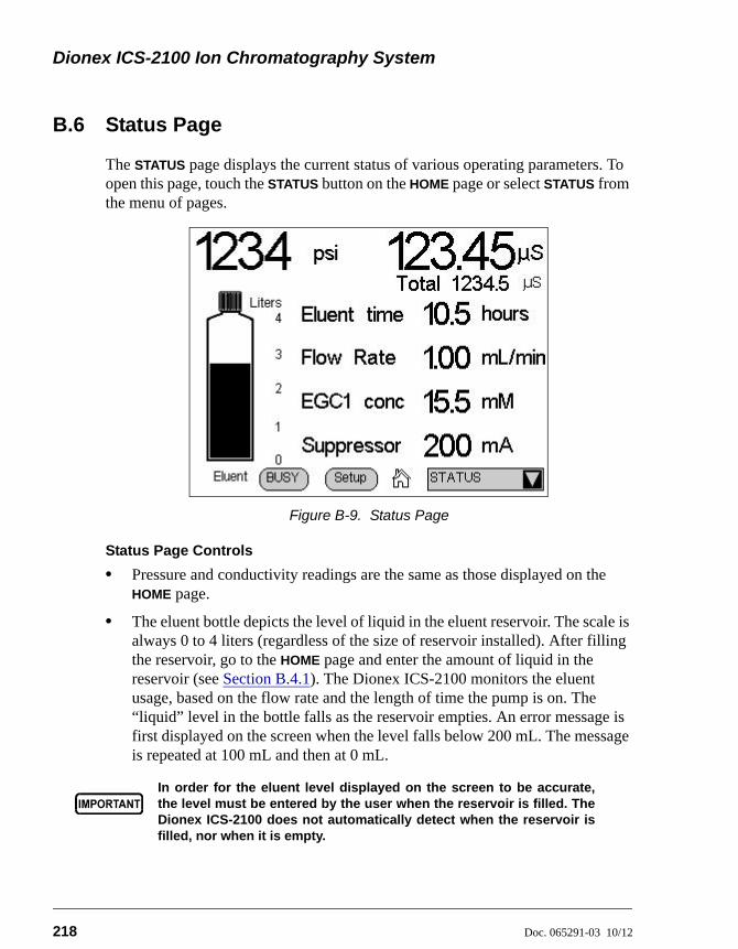
Dionex ICS-2100 Ion Chromatography System
218 Doc. 065291-03 10/12
B.6 Status Page
The STATUS page displays the current status of various operating parameters. To open this page, touch the STATUS button on the HOME page or select STATUS from the menu of pages.
Status Page Controls
• Pressure and conductivity readings are the same as those displayed on the HOME page.
• The eluent bottle depicts the level of liquid in the eluent reservoir. The scale is always 0 to 4 liters (regardless of the size of reservoir installed). After filling the reservoir, go to the HOME page and enter the amount of liquid in the reservoir (see Section B.4.1). The Dionex ICS-2100 monitors the eluent usage, based on the flow rate and the length of time the pump is on. The “liquid” level in the bottle falls as the reservoir empties. An error message is first displayed on the screen when the level falls below 200 mL. The message is repeated at 100 mL and then at 0 mL.
Figure B-9. Status Page
In order for the eluent level displayed on the screen to be accurate,the level must be entered by the user when the reservoir is filled. TheDionex ICS-2100 does not automatically detect when the reservoir isfilled, nor when it is empty.
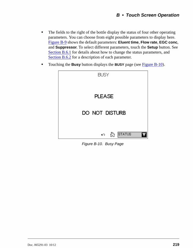
B • Touch Screen Operation
Doc. 065291-03 10/12 219
• The fields to the right of the bottle display the status of four other operating parameters. You can choose from eight possible parameters to display here. Figure B-9 shows the default parameters: Eluent time, Flow rate, EGC conc, and Suppressor. To select different parameters, touch the Setup button. See Section B.6.1 for details about how to change the status parameters, and Section B.6.2 for a description of each parameter.
• Touching the Busy button displays the BUSY page (see Figure B-10).
Figure B-10. Busy Page
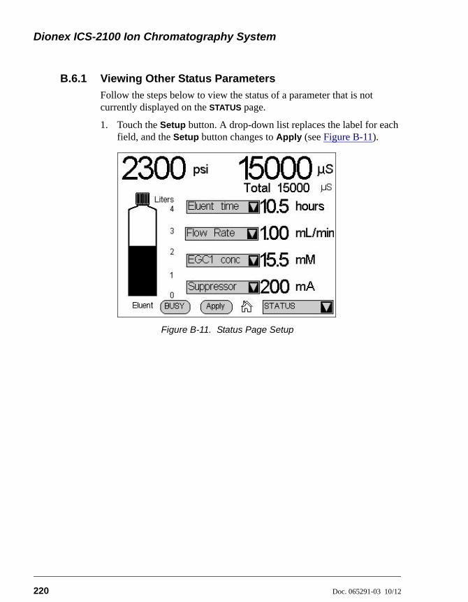
Dionex ICS-2100 Ion Chromatography System
220 Doc. 065291-03 10/12
B.6.1 Viewing Other Status Parameters
Follow the steps below to view the status of a parameter that is not currently displayed on the STATUS page.
1. Touch the Setup button. A drop-down list replaces the label for each field, and the Setup button changes to Apply (see Figure B-11).
Figure B-11. Status Page Setup
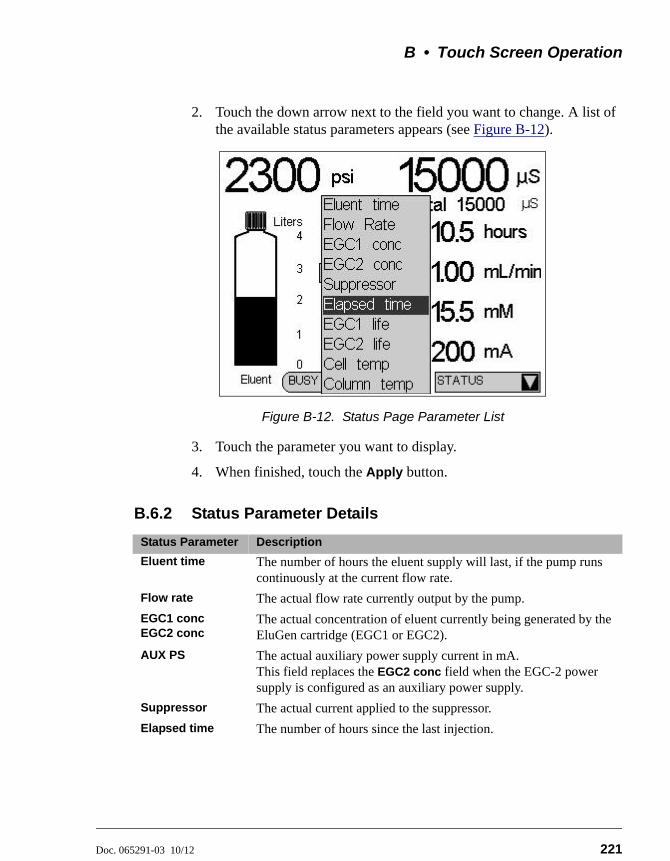
B • Touch Screen Operation
Doc. 065291-03 10/12 221
2. Touch the down arrow next to the field you want to change. A list of the available status parameters appears (see Figure B-12).
3. Touch the parameter you want to display.
4. When finished, touch the Apply button.
B.6.2 Status Parameter Details
Figure B-12. Status Page Parameter List
Status Parameter Description
Eluent time The number of hours the eluent supply will last, if the pump runs continuously at the current flow rate.
Flow rate The actual flow rate currently output by the pump.
EGC1 concEGC2 conc
The actual concentration of eluent currently being generated by the EluGen cartridge (EGC1 or EGC2).
AUX PS The actual auxiliary power supply current in mA.This field replaces the EGC2 conc field when the EGC-2 power supply is configured as an auxiliary power supply.
Suppressor The actual current applied to the suppressor.
Elapsed time The number of hours since the last injection.
Dionex ICS-2100 Ion Chromatography System
222 Doc. 065291-03 10/12
EGC1 lifeEGC2 life
The percentage of ions remaining in the EluGen cartridge (EGC1 or EGC2).When the EGC-2 power supply is configured as an auxiliary power supply, the EGC2 life field will display N/A.
Cell temp The temperature of the cell heater (°C), followed by a status symbol (=, , or .
Column temp The temperature of the column heater (°C), followed by a status symbol (=, , or .
Status Parameter Description
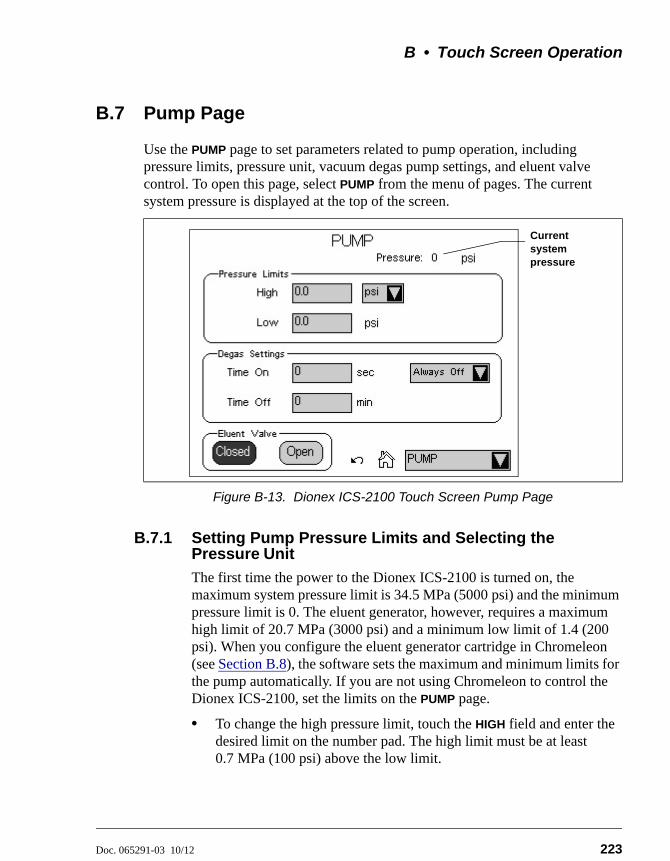
B • Touch Screen Operation
Doc. 065291-03 10/12 223
B.7 Pump Page
Use the PUMP page to set parameters related to pump operation, including pressure limits, pressure unit, vacuum degas pump settings, and eluent valve control. To open this page, select PUMP from the menu of pages. The current system pressure is displayed at the top of the screen.
B.7.1 Setting Pump Pressure Limits and Selecting the Pressure Unit
The first time the power to the Dionex ICS-2100 is turned on, the maximum system pressure limit is 34.5 MPa (5000 psi) and the minimum pressure limit is 0. The eluent generator, however, requires a maximum high limit of 20.7 MPa (3000 psi) and a minimum low limit of 1.4 (200 psi). When you configure the eluent generator cartridge in Chromeleon (see Section B.8), the software sets the maximum and minimum limits for the pump automatically. If you are not using Chromeleon to control the Dionex ICS-2100, set the limits on the PUMP page.
• To change the high pressure limit, touch the HIGH field and enter the desired limit on the number pad. The high limit must be at least 0.7 MPa (100 psi) above the low limit.
Figure B-13. Dionex ICS-2100 Touch Screen Pump Page
Current system pressure
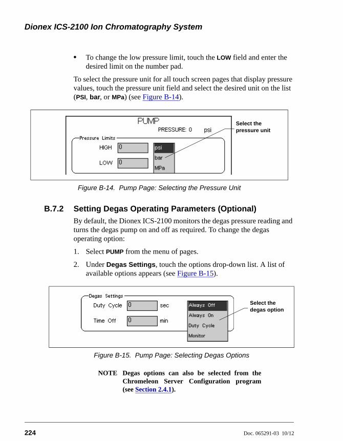
Dionex ICS-2100 Ion Chromatography System
224 Doc. 065291-03 10/12
• To change the low pressure limit, touch the LOW field and enter the desired limit on the number pad.
To select the pressure unit for all touch screen pages that display pressure values, touch the pressure unit field and select the desired unit on the list (PSI, bar, or MPa) (see Figure B-14).
B.7.2 Setting Degas Operating Parameters (Optional)
By default, the Dionex ICS-2100 monitors the degas pressure reading and turns the degas pump on and off as required. To change the degas operating option:
1. Select PUMP from the menu of pages.
2. Under Degas Settings, touch the options drop-down list. A list of available options appears (see Figure B-15).
NOTE Degas options can also be selected from theChromeleon Server Configuration program(see Section 2.4.1).
Figure B-14. Pump Page: Selecting the Pressure Unit
Figure B-15. Pump Page: Selecting Degas Options
Select the pressure unit
Select the degas option
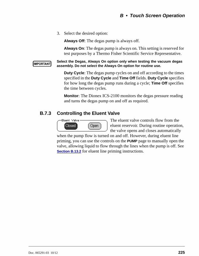
B • Touch Screen Operation
Doc. 065291-03 10/12 225
3. Select the desired option:
Always Off: The degas pump is always off.
Always On: The degas pump is always on. This setting is reserved for test purposes by a Thermo Fisher Scientific Service Representative.
Duty Cycle: The degas pump cycles on and off according to the times specified in the Duty Cycle and Time Off fields. Duty Cycle specifies for how long the degas pump runs during a cycle; Time Off specifies the time between cycles.
Monitor: The Dionex ICS-2100 monitors the degas pressure reading and turns the degas pump on and off as required.
B.7.3 Controlling the Eluent Valve
The eluent valve controls flow from the eluent reservoir. During routine operation, the valve opens and closes automatically
when the pump flow is turned on and off. However, during eluent line priming, you can use the controls on the PUMP page to manually open the valve, allowing liquid to flow through the lines when the pump is off. See Section B.13.2 for eluent line priming instructions.
Select the Degas, Always On option only when testing the vacuum degasassembly. Do not select the Always On option for routine use.
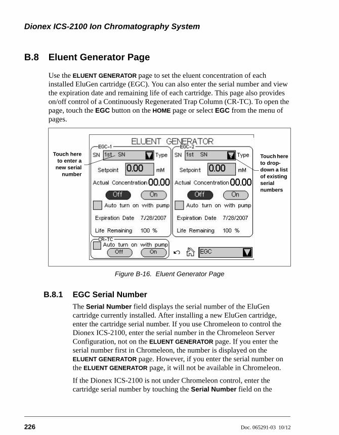
Dionex ICS-2100 Ion Chromatography System
226 Doc. 065291-03 10/12
B.8 Eluent Generator Page
Use the ELUENT GENERATOR page to set the eluent concentration of each installed EluGen cartridge (EGC). You can also enter the serial number and view the expiration date and remaining life of each cartridge. This page also provides on/off control of a Continuously Regenerated Trap Column (CR-TC). To open the page, touch the EGC button on the HOME page or select EGC from the menu of pages.
B.8.1 EGC Serial Number
The Serial Number field displays the serial number of the EluGen cartridge currently installed. After installing a new EluGen cartridge, enter the cartridge serial number. If you use Chromeleon to control the Dionex ICS-2100, enter the serial number in the Chromeleon Server Configuration, not on the ELUENT GENERATOR page. If you enter the serial number first in Chromeleon, the number is displayed on the ELUENT GENERATOR page. However, if you enter the serial number on the ELUENT GENERATOR page, it will not be available in Chromeleon.
If the Dionex ICS-2100 is not under Chromeleon control, enter the cartridge serial number by touching the Serial Number field on the
Figure B-16. Eluent Generator Page
Touch hereto enter a
new serialnumber
Touch here to drop-down a list of existing serial numbers
B • Touch Screen Operation
Doc. 065291-03 10/12 227
ELUENT GENERATOR page (see Figure B-16) and entering the serial number on the keypad.
If you are reinstalling a cartridge that was used previously, touch the down arrow instead of the number field. A list of the last five entered serial numbers drops down. Choose the serial number of the cartridge from the list.
NOTE When the EGC-2 power supply is configured as anauxiliary power supply, the EGC-2 Serial Numberfield displays None.
B.8.2 Setting the Eluent Concentration
To set the concentration of eluent to be generated, touch the Setpoint field and enter the concentration on the keypad. If the Dionex ICS-2100 power is turned off, the setpoint value is restored when the power is turned on again. The Actual Concentration field displays the concentration of eluent currently being generated.
The suppressor type, EGC type, and flow rate determine the maximum eluent concentration for a particular application. To determine the eluent concentration for your application, refer to the column manual. Column manuals are included on the Thermo Scientific Reference Library DVD (P/N 053891).
If a K2CO3 EluGen cartridge and an EPM Electrolytic pH Modifier are installed (connected to EGC-1 and EGC-2, respectively), set EGC-1 to the concentration of K2CO3 required for your application and set EGC-2 to the concentration of KHCO3 required. When the eluent is generated, the EGC-1 Actual Concentration field displays the total of the two setpoint concentrations. This is the actual concentration of K2CO3 that the cartridge must generate in order to achieve the desired K2CO3/KHCO3 eluent mixture.
For example, for a 3.50 mM K2CO3/1.00 mM KHCO3 eluent, set EGC-1 to 3.50 mM and EGC-2 to 1.00 mM. When the eluent is generated, the EGC-1 Actual Concentration field will display 4.50 mM.
NOTE When the EGC-2 power supply is configured as anauxiliary power supply, the EGC-2 Setpoint andActual Concentration fields display zeros.
Dionex ICS-2100 Ion Chromatography System
228 Doc. 065291-03 10/12
B.8.3 Controlling the Eluent Generator Power
• To manually control the eluent generator power, touch the EGC Off and On buttons on the ELUENT GENERATOR page.
• To automatically control the eluent generator power simultaneously with the pump flow, select Auto turn on with pump.
NOTE The eluent generator power always turns offwhen the pump is off, regardless of whether the“Automatically turn on with pump” option isselected.
NOTE When the EGC-2 power supply is configured asan auxiliary power supply, the EGC-2 Off andOn buttons are not functional and the fieldalways displays Off.
• To automatically control the auxiliary power supply simultaneously with the pump flow, select Auto turn on with pump for the EGC-2 and configure a TTL output for control of this function.
B.8.4 Monitoring the EluGen Cartridge Life
• The Expiration Date displayed on the ELUENT GENERATOR page is 2 years from the date of manufacture. Although you can continue operation with the cartridge after the expiration date, performance may be impaired until a new cartridge is installed.
NOTE When the EGC-2 power supply is configured asan auxiliary power supply, the EGC-2Expiration Date field is blank.
• Life Remaining (displayed when an EluGen cartridge is installed) indicates the percentage of ions remaining in the cartridge. The ion percentage is counted down in 1% increments. Warning messages are displayed in the Chromeleon Audit Trail when the percentage falls below 30%. At 0%, an error message informs you that the ion count is depleted and the cartridge must be replaced before continuing operation.
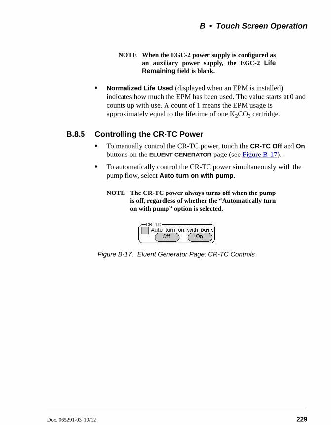
B • Touch Screen Operation
Doc. 065291-03 10/12 229
NOTE When the EGC-2 power supply is configured asan auxiliary power supply, the EGC-2 LifeRemaining field is blank.
• Normalized Life Used (displayed when an EPM is installed) indicates how much the EPM has been used. The value starts at 0 and counts up with use. A count of 1 means the EPM usage is approximately equal to the lifetime of one K2CO3 cartridge.
B.8.5 Controlling the CR-TC Power
• To manually control the CR-TC power, touch the CR-TC Off and On buttons on the ELUENT GENERATOR page (see Figure B-17).
• To automatically control the CR-TC power simultaneously with the pump flow, select Auto turn on with pump.
NOTE The CR-TC power always turns off when the pumpis off, regardless of whether the “Automatically turnon with pump” option is selected.
Figure B-17. Eluent Generator Page: CR-TC Controls
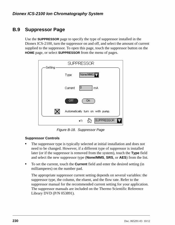
Dionex ICS-2100 Ion Chromatography System
230 Doc. 065291-03 10/12
B.9 Suppressor Page
Use the SUPPRESSOR page to specify the type of suppressor installed in the Dionex ICS-2100, turn the suppressor on and off, and select the amount of current supplied to the suppressor. To open this page, touch the suppressor button on the HOME page, or select SUPPRESSOR from the menu of pages.
Suppressor Controls
• The suppressor type is typically selected at initial installation and does not need to be changed. However, if a different type of suppressor is installed later (or if the suppressor is removed from the system), touch the Type field and select the new suppressor type (None/MMS, SRS, or AES) from the list.
• To set the current, touch the Current field and enter the desired setting (in milliamperes) on the number pad.
The appropriate suppressor current setting depends on several variables: the suppressor type, the column, the eluent, and the flow rate. Refer to the suppressor manual for the recommended current setting for your application. The suppressor manuals are included on the Thermo Scientific Reference Library DVD (P/N 053891).
Figure B-18. Suppressor Page
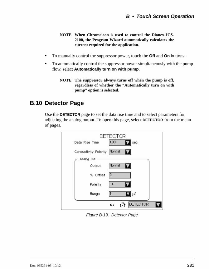
B • Touch Screen Operation
Doc. 065291-03 10/12 231
NOTE When Chromeleon is used to control the Dionex ICS-2100, the Program Wizard automatically calculates thecurrent required for the application.
• To manually control the suppressor power, touch the Off and On buttons.
• To automatically control the suppressor power simultaneously with the pump flow, select Automatically turn on with pump.
NOTE The suppressor always turns off when the pump is off,regardless of whether the “Automatically turn on withpump” option is selected.
B.10 Detector Page
Use the DETECTOR page to set the data rise time and to select parameters for adjusting the analog output. To open this page, select DETECTOR from the menu of pages.
Figure B-19. Detector Page
Dionex ICS-2100 Ion Chromatography System
232 Doc. 065291-03 10/12
B.10.1 Setting the Data Rise Time
The data rise time determines the amount of filtering performed on the conductivity data. The rise time is a measure of how quickly the detector responds to a change in signal, and is defined as the time it takes the output signal to rise from 10% of its final value to 90% of its final value.
The selected data rise time is used to filter both the digital data output, which is sent to the computer and the PLOT page, and the analog data output. The default rise time is 2 seconds.
Choosing an appropriate rise time value can optimize performance by keeping the signal-to-noise ratio at a minimum level. A longer rise time allows averaging of the noise frequencies, and subsequently, the baseline will contain much less short-term noise. However, longer rise times may have the following effects on peaks:
• Peak shape will become asymmetric.
• The peak maximum will be shifted.
• The peak height will be reduced.
The rise time should be approximately 25% of the peak width at one-half the height of the narrowest peak of interest.
For example, for a peak width of 5 seconds, calculate the rise time as: (5 sec) 25% = 1.25 sec. Because 1.25 seconds is not one of the available settings for rise time, select the next fastest rise time, 1 second.
To set the data rise time, touch the Data Rise Time field and select the desired time from the list (see Figure B-19).
B.10.2 Selecting the Conductivity Polarity
To change the polarity of the conductivity data, touch the Conductivity Polarity field. Select either Normal or Inverted. In applications in which the analyte output is lower than the background conductance, the polarity must be inverted to have peaks instead of dips on the chromatogram.
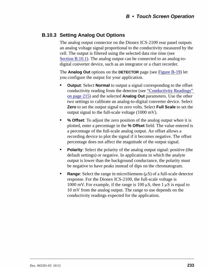
B • Touch Screen Operation
Doc. 065291-03 10/12 233
B.10.3 Setting Analog Out Options
The analog output connector on the Dionex ICS-2100 rear panel outputs an analog voltage signal proportional to the conductivity measured by the cell. The output is filtered using the selected data rise time (see Section B.10.1). The analog output can be connected to an analog-to-digital converter device, such as an integrator or a chart recorder.
The Analog Out options on the DETECTOR page (see Figure B-19) let you configure the output for your application.
• Output: Select Normal to output a signal corresponding to the offset conductivity reading from the detector (see “Conductivity Readings” on page 215) and the selected Analog Out parameters. Use the other two settings to calibrate an analog-to-digital converter device. Select Zero to set the output signal to zero volts. Select Full Scale to set the output signal to the full-scale voltage (1000 mV).
• % Offset: To adjust the zero position of the analog output when it is plotted, enter a percentage in the % Offset field. The value entered is a percentage of the full-scale analog output. An offset allows a recording device to plot the signal if it becomes negative. The offset percentage does not affect the magnitude of the output signal.
• Polarity: Select the polarity of the analog output signal: positive (the default settings) or negative. In applications in which the analyte output is lower than the background conductance, the polarity must be negative to have peaks instead of dips on the chromatogram.
• Range: Select the range in microSiemens (S) of a full-scale detector response. For the Dionex ICS-2100, the full-scale voltage is 1000 mV. For example, if the range is 100 S, then 1 S is equal to 10 mV from the analog output. The range to use depends on the conductivity readings expected for the application.
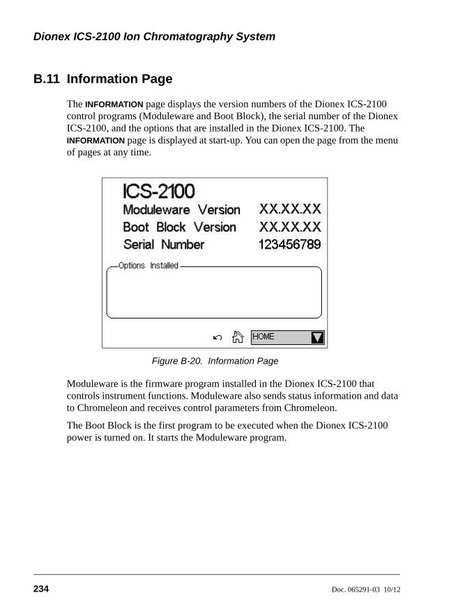
Dionex ICS-2100 Ion Chromatography System
234 Doc. 065291-03 10/12
B.11 Information Page
The INFORMATION page displays the version numbers of the Dionex ICS-2100 control programs (Moduleware and Boot Block), the serial number of the Dionex ICS-2100, and the options that are installed in the Dionex ICS-2100. The INFORMATION page is displayed at start-up. You can open the page from the menu of pages at any time.
Moduleware is the firmware program installed in the Dionex ICS-2100 that controls instrument functions. Moduleware also sends status information and data to Chromeleon and receives control parameters from Chromeleon.
The Boot Block is the first program to be executed when the Dionex ICS-2100 power is turned on. It starts the Moduleware program.
Figure B-20. Information Page
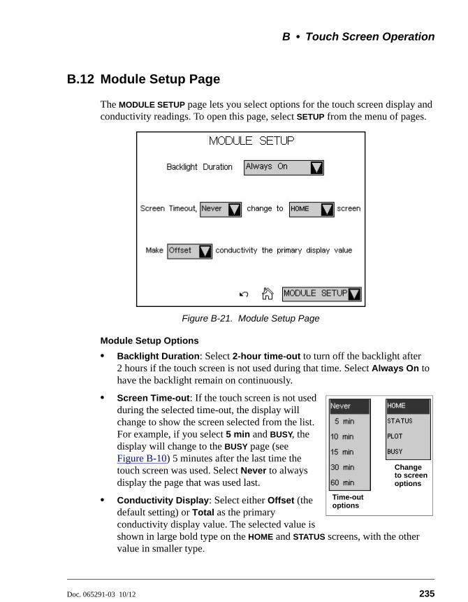
B • Touch Screen Operation
Doc. 065291-03 10/12 235
B.12 Module Setup Page
The MODULE SETUP page lets you select options for the touch screen display and conductivity readings. To open this page, select SETUP from the menu of pages.
Module Setup Options
• Backlight Duration: Select 2-hour time-out to turn off the backlight after 2 hours if the touch screen is not used during that time. Select Always On to have the backlight remain on continuously.
• Screen Time-out: If the touch screen is not used during the selected time-out, the display will change to show the screen selected from the list. For example, if you select 5 min and BUSY, the display will change to the BUSY page (see Figure B-10) 5 minutes after the last time the touch screen was used. Select Never to always display the page that was used last.
• Conductivity Display: Select either Offset (the default setting) or Total as the primary conductivity display value. The selected value is shown in large bold type on the HOME and STATUS screens, with the other value in smaller type.
Figure B-21. Module Setup Page
Time-outoptions
to screenoptions
Change
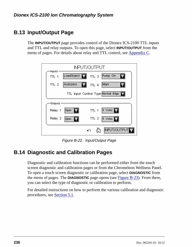
Dionex ICS-2100 Ion Chromatography System
236 Doc. 065291-03 10/12
B.13 Input/Output Page
The INPUT/OUTPUT page provides control of the Dionex ICS-2100 TTL inputs and TTL and relay outputs. To open this page, select INPUT/OUTPUT from the menu of pages. For details about relay and TTL control, see Appendix C.
B.14 Diagnostic and Calibration Pages
Diagnostic and calibration functions can be performed either from the touch screen diagnostic and calibration pages or from the Chromeleon Wellness Panel. To open a touch screen diagnostic or calibration page, select DIAGNOSTIC from the menu of pages. The DIAGNOSTIC page opens (see Figure B-23). From there, you can select the type of diagnostic or calibration to perform.
For detailed instructions on how to perform the various calibration and diagnostic procedures, see Section 5.1.
Figure B-22. Input/Output Page
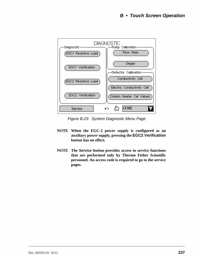
B • Touch Screen Operation
Doc. 065291-03 10/12 237
NOTE When the EGC-2 power supply is configured as anauxiliary power supply, pressing the EGC2 Verificationbutton has no effect.
NOTE The Service button provides access to service functionsthat are performed only by Thermo Fisher Scientificpersonnel. An access code is required to go to the servicepages.
Figure B-23. System Diagnostic Menu Page

Dionex ICS-2100 Ion Chromatography System
238 Doc. 065291-03 10/12
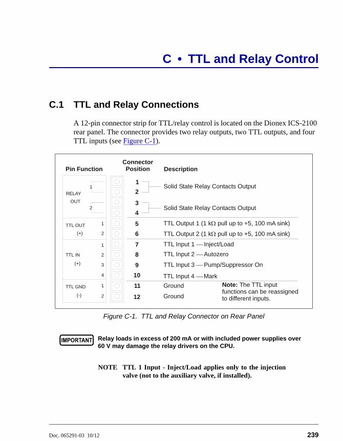
Doc. 065291-03 10/12 239
C • TTL and Relay Control
C.1 TTL and Relay Connections
A 12-pin connector strip for TTL/relay control is located on the Dionex ICS-2100 rear panel. The connector provides two relay outputs, two TTL outputs, and four TTL inputs (see Figure C-1).
NOTE TTL 1 Input - Inject/Load applies only to the injectionvalve (not to the auxiliary valve, if installed).
Figure C-1. TTL and Relay Connector on Rear Panel
Relay loads in excess of 200 mA or with included power supplies over60 V may damage the relay drivers on the CPU.
1
2
OUT
RELAY
(+)
TTL OUT
1
2
TTL GND
(-)
1
2
3
4
TTL IN
(+)
1
2
1
2
Description
Solid State Relay Contacts Output
Pin Function
3
4Solid State Relay Contacts Output
TTL Output 1 (1 k pull up to +5, 100 mA sink) 5
TTL Output 2 (1 k pull up to +5, 100 mA sink) 6
7
8
9
10
11
12 Ground
Ground
TTL Input 2 Autozero
TTL Input 3 Pump/Suppressor On
TTL Input 4 MarkNote: The TTL input functions can be reassigned to different inputs.
Connector Position
TTL Input 1 Inject/Load
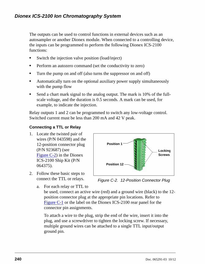
Dionex ICS-2100 Ion Chromatography System
240 Doc. 065291-03 10/12
The outputs can be used to control functions in external devices such as an autosampler or another Dionex module. When connected to a controlling device, the inputs can be programmed to perform the following Dionex ICS-2100 functions:
• Switch the injection valve position (load/inject)
• Perform an autozero command (set the conductivity to zero)
• Turn the pump on and off (also turns the suppressor on and off)
• Automatically turn on the optional auxiliary power supply simultaneously with the pump flow
• Send a chart mark signal to the analog output. The mark is 10% of the full-scale voltage, and the duration is 0.5 seconds. A mark can be used, for example, to indicate the injection.
Relay outputs 1 and 2 can be programmed to switch any low-voltage control. Switched current must be less than 200 mA and 42 V peak.
Connecting a TTL or Relay
1. Locate the twisted pair of wires (P/N 043598) and the 12-position connector plug (P/N 923687) (see Figure C-2) in the Dionex ICS-2100 Ship Kit (P/N 064375).
2. Follow these basic steps to connect the TTL or relays.
a. For each relay or TTL to be used, connect an active wire (red) and a ground wire (black) to the 12-position connector plug at the appropriate pin locations. Refer to Figure C-1 or the label on the Dionex ICS-2100 rear panel for the connector pin assignments.
To attach a wire to the plug, strip the end of the wire, insert it into the plug, and use a screwdriver to tighten the locking screw. If necessary, multiple ground wires can be attached to a single TTL input/output ground pin.
Figure C-2. 12-Position Connector Plug
Position 1
Position 12
LockingScrews
C • TTL and Relay Control
Doc. 065291-03 10/12 241
b. Plug the connector into the 12-pin connector on the Dionex ICS-2100 rear panel.
c. Connect the wires from the Dionex ICS-2100 connector plug to the TTL or relay connector pins on the other module(s). Additional connector plugs are provided with other Dionex modules.
NOTE Check the polarity of each connection. Connectsignal wires to signal (+) pins and ground wires toground (-) pins.
3. If you connected a TTL input, verify that the correct function is assigned to the input and that the correct input control type is selected. Select different settings, if necessary. Input functions and control types are assigned from either the INPUT/OUTPUT touch screen page or Chromeleon (see Section C.1.1).
When attaching wires to the connector plug, be careful not to allowstray strands of wire to short to the adjoining position on theconnector.
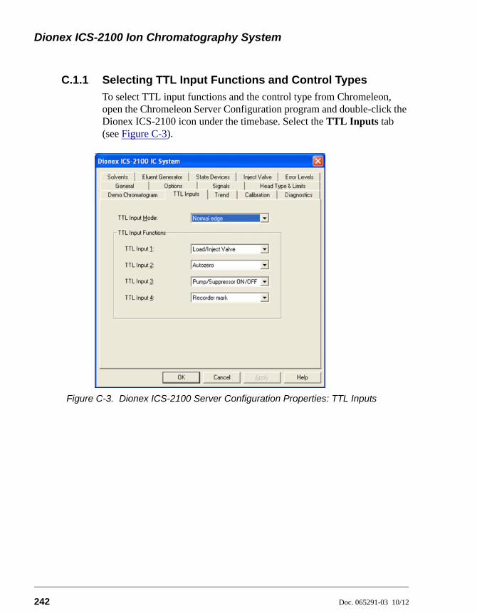
Dionex ICS-2100 Ion Chromatography System
242 Doc. 065291-03 10/12
C.1.1 Selecting TTL Input Functions and Control Types
To select TTL input functions and the control type from Chromeleon, open the Chromeleon Server Configuration program and double-click the Dionex ICS-2100 icon under the timebase. Select the TTL Inputs tab (see Figure C-3).
Figure C-3. Dionex ICS-2100 Server Configuration Properties: TTL Inputs
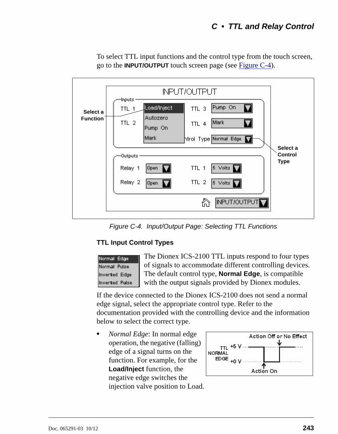
C • TTL and Relay Control
Doc. 065291-03 10/12 243
To select TTL input functions and the control type from the touch screen, go to the INPUT/OUTPUT touch screen page (see Figure C-4).
TTL Input Control Types
The Dionex ICS-2100 TTL inputs respond to four types of signals to accommodate different controlling devices. The default control type, Normal Edge, is compatible with the output signals provided by Dionex modules.
If the device connected to the Dionex ICS-2100 does not send a normal edge signal, select the appropriate control type. Refer to the documentation provided with the controlling device and the information below to select the correct type.
• Normal Edge: In normal edge operation, the negative (falling) edge of a signal turns on the function. For example, for the Load/Inject function, the negative edge switches the injection valve position to Load.
Figure C-4. Input/Output Page: Selecting TTL Functions
Select aFunction
Select a Control Type
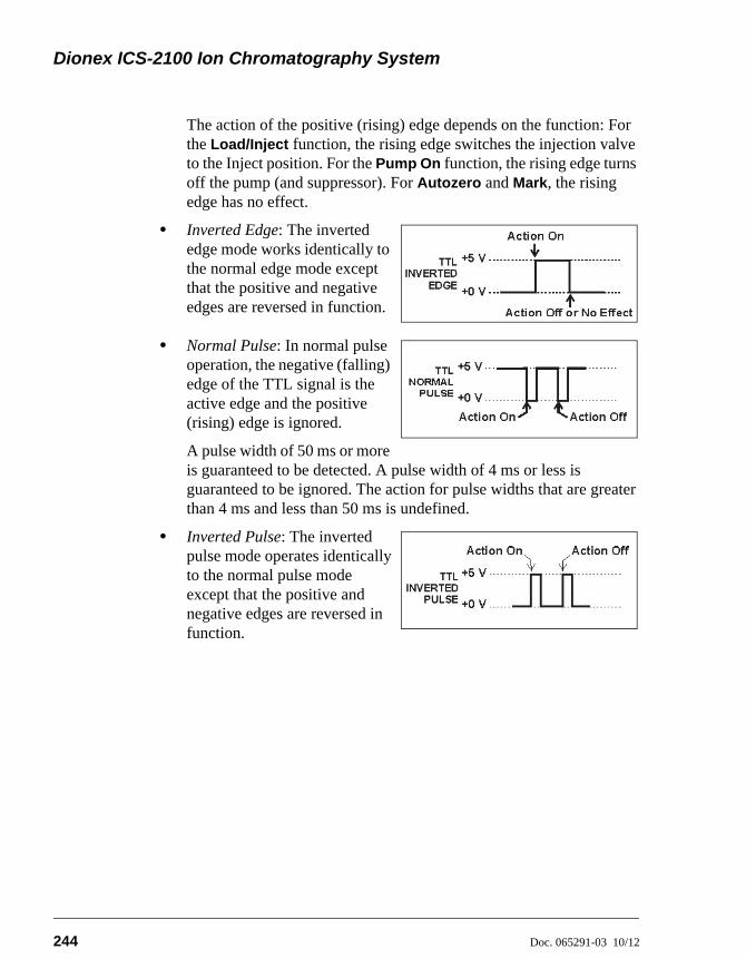
Dionex ICS-2100 Ion Chromatography System
244 Doc. 065291-03 10/12
The action of the positive (rising) edge depends on the function: For the Load/Inject function, the rising edge switches the injection valve to the Inject position. For the Pump On function, the rising edge turns off the pump (and suppressor). For Autozero and Mark, the rising edge has no effect.
• Inverted Edge: The inverted edge mode works identically to the normal edge mode except that the positive and negative edges are reversed in function.
• Normal Pulse: In normal pulse operation, the negative (falling) edge of the TTL signal is the active edge and the positive (rising) edge is ignored.
A pulse width of 50 ms or more is guaranteed to be detected. A pulse width of 4 ms or less is guaranteed to be ignored. The action for pulse widths that are greater than 4 ms and less than 50 ms is undefined.
• Inverted Pulse: The inverted pulse mode operates identically to the normal pulse mode except that the positive and negative edges are reversed in function.
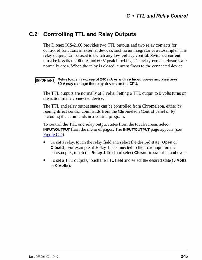
C • TTL and Relay Control
Doc. 065291-03 10/12 245
C.2 Controlling TTL and Relay Outputs
The Dionex ICS-2100 provides two TTL outputs and two relay contacts for control of functions in external devices, such as an integrator or autosampler. The relay outputs can be used to switch any low-voltage control. Switched current must be less than 200 mA and 60 V peak blocking. The relay-contact closures are normally open. When the relay is closed, current flows to the connected device.
The TTL outputs are normally at 5 volts. Setting a TTL output to 0 volts turns on the action in the connected device.
The TTL and relay output states can be controlled from Chromeleon, either by issuing direct control commands from the Chromeleon Control panel or by including the commands in a control program.
To control the TTL and relay output states from the touch screen, select INPUT/OUTPUT from the menu of pages. The INPUT/OUTPUT page appears (see Figure C-4).
• To set a relay, touch the relay field and select the desired state (Open or Closed). For example, if Relay 1 is connected to the Load input on the autosampler, touch the Relay 1 field and select Closed to start the load cycle.
• To set a TTL outputs, touch the TTL field and select the desired state (5 Volts or 0 Volts).
Relay loads in excess of 200 mA or with included power supplies over60 V may damage the relay drivers on the CPU.

Dionex ICS-2100 Ion Chromatography System
246 Doc. 065291-03 10/12
C.3 Example Setup for Stand-Alone Operation
This section describes an example setup for stand-alone operation (operation without Chromeleon software) with a Dionex AS Autosampler and a third-party analog-to-digital converter and controller. If your configuration includes different devices, use the following steps as guidelines and refer to your product documentation for specific connection details.
Connect the Dionex AS Autosampler
Follow the instructions in the Dionex ICS-2100 installation instructions to connect the Dionex AS Autosampler to the Dionex ICS-2100 injection valve.
Connect the TTLs and Relays
1. Locate two twisted pairs of wires (P/N 043598) and 12-position connector plugs (P/N 923686) (see Figure C-5) in the Dionex ICS-2100 and Dionex AS Ship Kits.
2. Attach the wires to the connector plug positions indicated in Figure C-6.
To attach a wire to a connector plug, strip the ends of the wire, insert into the desired connector position, and tighten the locking screw with a screwdriver.
3. Plug the connector plugs into their respective TTL/Relay connectors on the rear panel of each module.
Make sure the red wires connect to active (+) pins on each module and the black wires connect to ground (-) pins.
When attaching wires to the connector plug, be careful not to allowstray strands of wire to short to the adjoining position on theconnector.
Figure C-5. 12-Position Connector Plug
Position 1
Position 12
Locking Screws
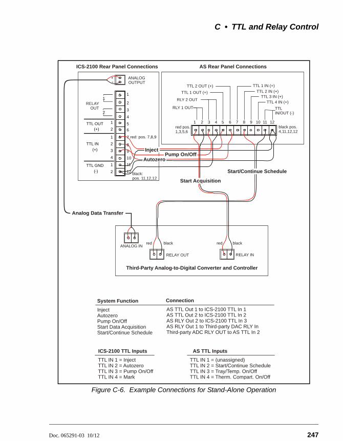
C • TTL and Relay Control
Doc. 065291-03 10/12 247
Figure C-6. Example Connections for Stand-Alone Operation
ICS-2100 TTL Inputs
TTL IN 1 = InjectTTL IN 2 = AutozeroTTL IN 3 = Pump On/OffTTL IN 4 = Mark
AS TTL Inputs
TTL IN 1 = (unassigned)TTL IN 2 = Start/Continue ScheduleTTL IN 3 = Tray/Temp. On/OffTTL IN 4 = Therm. Compart. On/Off
System Function
InjectAutozero
Start/Continue Schedule
Pump On/OffStart Data Acquisition
AS TTL Out 1 to ICS-2100 TTL In 1
to AS TTL In 2
AS TTL Out 2 to ICS-2100 TTL In 2AS RLY Out 2 to ICS-2100 TTL In 3AS RLY Out 1 to Third-party DAC RLY InThird-party ADC RLY OUT
Connection
Analog Data Transfer
AS Rear Panel ConnectionsICS-2100 Rear Panel Connections
red: pos. 7,8,9
1 2 3 4 5 6 7 8 9 10 11 121
2(+)TTL OUT
1
2
TTL GND
(-)
1
2
3
4
TTL IN
(+)
1
2
RELAY OUT
TTL 2 OUT (+)
TTL 1 OUT (+)
RLY 2 OUT
RLY 1 OUT
TTL 1 IN (+)TTL 2 IN (+)
TTL 3 IN (+)TTL 4 IN (+)
TTL IN/OUT (-)
Third-Party Analog-to-Digital Converter and Controller
RELAY OUT
red pos.1,3,5,6
red black red black
Start/Continue Schedule
Inject
1
2
3
4
5
6
7
8
9
10
11
12
black pos.4,11,12,12
Autozero
ANALOG OUTPUT
+-
ANALOG IN
Pump On/Off
black: pos. 11,12,12
Start Acquisition
RELAY IN
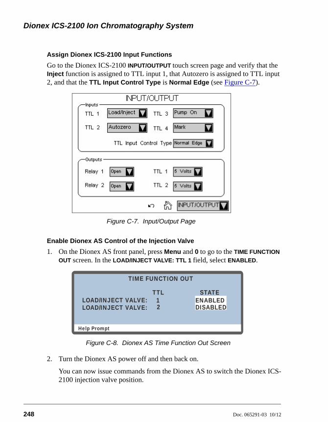
Dionex ICS-2100 Ion Chromatography System
248 Doc. 065291-03 10/12
Assign Dionex ICS-2100 Input Functions
Go to the Dionex ICS-2100 INPUT/OUTPUT touch screen page and verify that the Inject function is assigned to TTL input 1, that Autozero is assigned to TTL input 2, and that the TTL Input Control Type is Normal Edge (see Figure C-7).
Enable Dionex AS Control of the Injection Valve
1. On the Dionex AS front panel, press Menu and 0 to go to the TIME FUNCTION
OUT screen. In the LOAD/INJECT VALVE: TTL 1 field, select ENABLED.
2. Turn the Dionex AS power off and then back on.
You can now issue commands from the Dionex AS to switch the Dionex ICS-2100 injection valve position.
Figure C-7. Input/Output Page
Figure C-8. Dionex AS Time Function Out Screen
Help Prompt
TIME FUNCTION OUT
TTL12
LOAD/INJECT VALVE:LOAD/INJECT VALVE:
ENABLEDDISABLED
STATE
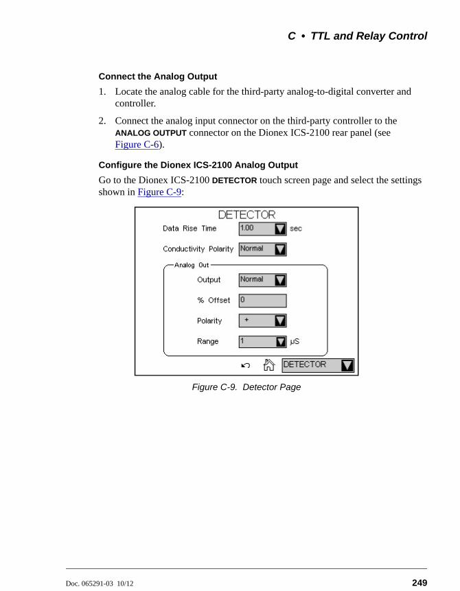
C • TTL and Relay Control
Doc. 065291-03 10/12 249
Connect the Analog Output
1. Locate the analog cable for the third-party analog-to-digital converter and controller.
2. Connect the analog input connector on the third-party controller to the ANALOG OUTPUT connector on the Dionex ICS-2100 rear panel (see Figure C-6).
Configure the Dionex ICS-2100 Analog Output
Go to the Dionex ICS-2100 DETECTOR touch screen page and select the settings shown in Figure C-9:
Figure C-9. Detector Page
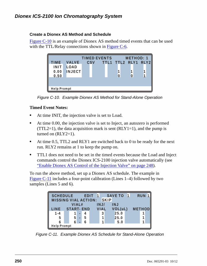
Dionex ICS-2100 Ion Chromatography System
250 Doc. 065291-03 10/12
Create a Dionex AS Method and Schedule
Figure C-10 is an example of Dionex AS method timed events that can be used with the TTL/Relay connections shown in Figure C-6.
Timed Event Notes:
• At time INIT, the injection valve is set to Load.
• At time 0.00, the injection valve is set to Inject, an autozero is performed (TTL2=1), the data acquisition mark is sent (RLY1=1), and the pump is turned on (RLY2=1).
• At time 0.5, TTL2 and RLY1 are switched back to 0 to be ready for the next run. RLY2 remains at 1 to keep the pump on.
• TTL1 does not need to be set in the timed events because the Load and Inject commands control the Dionex ICS-2100 injection valve automatically (see “Enable Dionex AS Control of the Injection Valve” on page 248).
To run the above method, set up a Dionex AS schedule. The example in Figure C-11 includes a four-point calibration (Lines 1–4) followed by two samples (Lines 5 and 6).
Figure C-10. Example Dionex AS Method for Stand-Alone Operation
Figure C-11. Example Dionex AS Schedule for Stand-Alone Operation
Help Prompt
METHOD:TIMED EVENTS
1 1 1
TIMEINIT LOAD
INJECT0.00
VALVE TTL1 TTL2 RLY1 RLY21
CSV
0 0 10.50
Help Prompt
SAVE TO RUNSCHEDULE
25.0
5.0
1
1
1 4 35 5 16 6 1
1
MISSING VIAL ACTION:INJ/ INJVIAL METHODVOL(uL)
VIAL#LINE ENDSTART
EDITSKIP
11 1
1-456
--
--
25.0
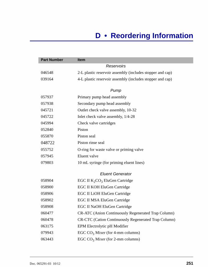
Doc. 065291-03 10/12 251
D • Reordering Information
Part Number Item
Reservoirs
046548 2-L plastic reservoir assembly (includes stopper and cap)
039164 4-L plastic reservoir assembly (includes stopper and cap)
Pump
057937 Primary pump head assembly
057938 Secondary pump head assembly
045721 Outlet check valve assembly, 10-32
045722 Inlet check valve assembly, 1/4-28
045994 Check valve cartridges
052840 Piston
055870 Piston seal
048722 Piston rinse seal
055752 O-ring for waste valve or priming valve
057945 Eluent valve
079803 10 mL syringe (for priming eluent lines)
Eluent Generator
058904 EGC II K2CO3 EluGen Cartridge
058900 EGC II KOH EluGen Cartridge
058906 EGC II LiOH EluGen Cartridge
058902 EGC II MSA EluGen Cartridge
058908 EGC II NaOH EluGen Cartridge
060477 CR-ATC (Anion Continuously Regenerated Trap Column)
060478 CR-CTC (Cation Continuously Regenerated Trap Column)
063175 EPM Electrolytic pH Modifier
079943 EGC CO3 Mixer (for 4-mm columns)
063443 EGC CO3 Mixer (for 2-mm columns)
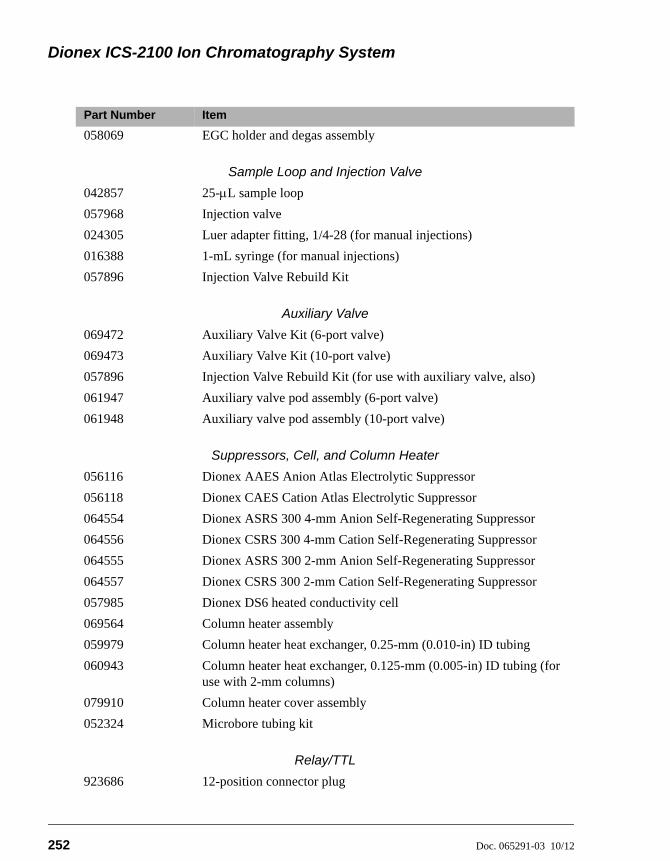
Dionex ICS-2100 Ion Chromatography System
252 Doc. 065291-03 10/12
058069 EGC holder and degas assembly
Sample Loop and Injection Valve
042857 25-L sample loop
057968 Injection valve
024305 Luer adapter fitting, 1/4-28 (for manual injections)
016388 1-mL syringe (for manual injections)
057896 Injection Valve Rebuild Kit
Auxiliary Valve
069472 Auxiliary Valve Kit (6-port valve)
069473 Auxiliary Valve Kit (10-port valve)
057896 Injection Valve Rebuild Kit (for use with auxiliary valve, also)
061947 Auxiliary valve pod assembly (6-port valve)
061948 Auxiliary valve pod assembly (10-port valve)
Suppressors, Cell, and Column Heater
056116 Dionex AAES Anion Atlas Electrolytic Suppressor
056118 Dionex CAES Cation Atlas Electrolytic Suppressor
064554 Dionex ASRS 300 4-mm Anion Self-Regenerating Suppressor
064556 Dionex CSRS 300 4-mm Cation Self-Regenerating Suppressor
064555 Dionex ASRS 300 2-mm Anion Self-Regenerating Suppressor
064557 Dionex CSRS 300 2-mm Cation Self-Regenerating Suppressor
057985 Dionex DS6 heated conductivity cell
069564 Column heater assembly
059979 Column heater heat exchanger, 0.25-mm (0.010-in) ID tubing
060943 Column heater heat exchanger, 0.125-mm (0.005-in) ID tubing (for use with 2-mm columns)
079910 Column heater cover assembly
052324 Microbore tubing kit
Relay/TTL
923686 12-position connector plug
Part Number Item
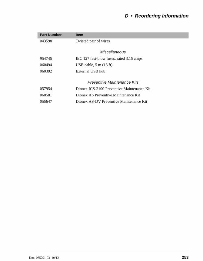
D • Reordering Information
Doc. 065291-03 10/12 253
043598 Twisted pair of wires
Miscellaneous
954745 IEC 127 fast-blow fuses, rated 3.15 amps
060494 USB cable, 5 m (16 ft)
060392 External USB hub
Preventive Maintenance Kits
057954 Dionex ICS-2100 Preventive Maintenance Kit
060581 Dionex AS Preventive Maintenance Kit
055647 Dionex AS-DV Preventive Maintenance Kit
Part Number Item

Dionex ICS-2100 Ion Chromatography System
254 Doc. 065291-03 10/12
Doc. 065291-03 10/12 255
E • FAQ
E.1 How do I hook up an autosampler?
For instructions on how to connect the Dionex ICS-2100 to an autosampler, refer to the Dionex ICS-2100 installation instructions. Also refer to the autosampler operator’s manuals, which are included on the Thermo Scientific Reference Library DVD (P/N 053891).
E.2 How do I print?
Click the Print toolbar button in Chromeleon.
E.3 Why are the retention times moving?
Retention times can shift if the pump flow is erratic or if the column or eluent is contaminated. See Section 4.7 for pump flow rate troubleshooting. If a contaminated column is suspected, clean the column as instructed in the column manual. The column manual is included on the Thermo Scientific Reference Library DVD (P/N 053891).
E.4 How do I adjust retention times?
Retention times are calculated during calibration. The Use Recently Detected Retention Time parameter in the Chromeleon QNT Editor (General tab) can be used to compensate for some types of retention time drifts; for example, evaporation of volatile components in pre-mixed solvents or an aging column. Refer to the Chromeleon Help or user’s manual for details.
E.5 When should I remake standards?
Standards are used only for calibration and should always be made fresh (they have a lifetime of only one week).

Dionex ICS-2100 Ion Chromatography System
256 Doc. 065291-03 10/12
E.6 When should I replace the eluent generator cartridge?
The Dionex ICS-2100 monitors EluGen cartridge use and displays a message when it is time to replace the cartridge. The message appears on the front panel screen and in the Chromeleon Audit Trail. To view the remaining cartridge life, click EG Settings on the Chromeleon Control panel, or go to the touch screen ELUENT GENERATOR page (see Section B.8).
E.7 How do I start Chromeleon?
Click Start on the Windows taskbar, and then select All Programs > Chromeleon > Chromeleon.
E.8 How do I delete data?
In the Chromeleon Browser, highlight the sequence you want to delete and then select File > Delete.
E.9 How do I back up data?
In Chromeleon, select File > Export/Backup. Back up the data and indicate the backup source.
E.10 How do I shut off the system?
In Chromeleon, click the System Shutdown button on the Dionex ICS-2100 Control panel. On the instrument, turn off the power switch on the rear panel (see Figure 2-9).
E.11 How do I store columns?
Columns should be stored in eluent. See the column manual for complete instructions. The column manual is included on the Thermo Scientific Reference Library DVD (P/N 053891).
E • FAQ
Doc. 065291-03 10/12 257
E.12 How do I know when a column is dirty?
See the troubleshooting section of the column manual.
E.13 How do I clean a column?
See the troubleshooting section of the column manual.
E.14 Why is the conductivity high?
Possible reasons for high conductivity include:
• The suppressor is not on. Turn on the suppressor from the Chromeleon Control panel or the Dionex ICS-2100 touch screen SUPPRESSOR page.
• The suppressor needs regeneration. See the suppressor manual for troubleshooting information. The suppressor manual is included on the Thermo Scientific Reference Library DVD (P/N 053891).
• The cell is out of calibration. See Section 5.1.3 for calibration instructions.
• See Section 4.13 for additional troubleshooting information.
E.15 How do I configure and operate the auxiliary valve?
See Installing the ICS-1100/ICS-1600/ICS-2100 Auxiliary Valve (Document No. 065288), provided in the Auxiliary Valve Kit.

Dionex ICS-2100 Ion Chromatography System
258 Doc. 065291-03 10/12
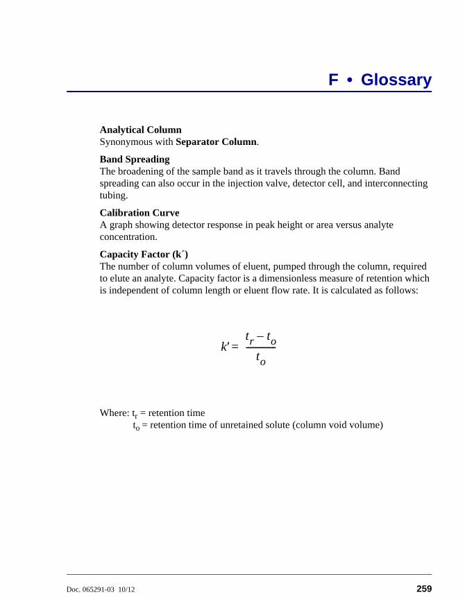
Doc. 065291-03 10/12 259
F • Glossary
Analytical ColumnSynonymous with Separator Column.
Band SpreadingThe broadening of the sample band as it travels through the column. Band spreading can also occur in the injection valve, detector cell, and interconnecting tubing.
Calibration CurveA graph showing detector response in peak height or area versus analyte concentration.
Capacity Factor (k´)The number of column volumes of eluent, pumped through the column, required to elute an analyte. Capacity factor is a dimensionless measure of retention which is independent of column length or eluent flow rate. It is calculated as follows:
Where: tr = retention timeto = retention time of unretained solute (column void volume)
ktr to–
to--------------=
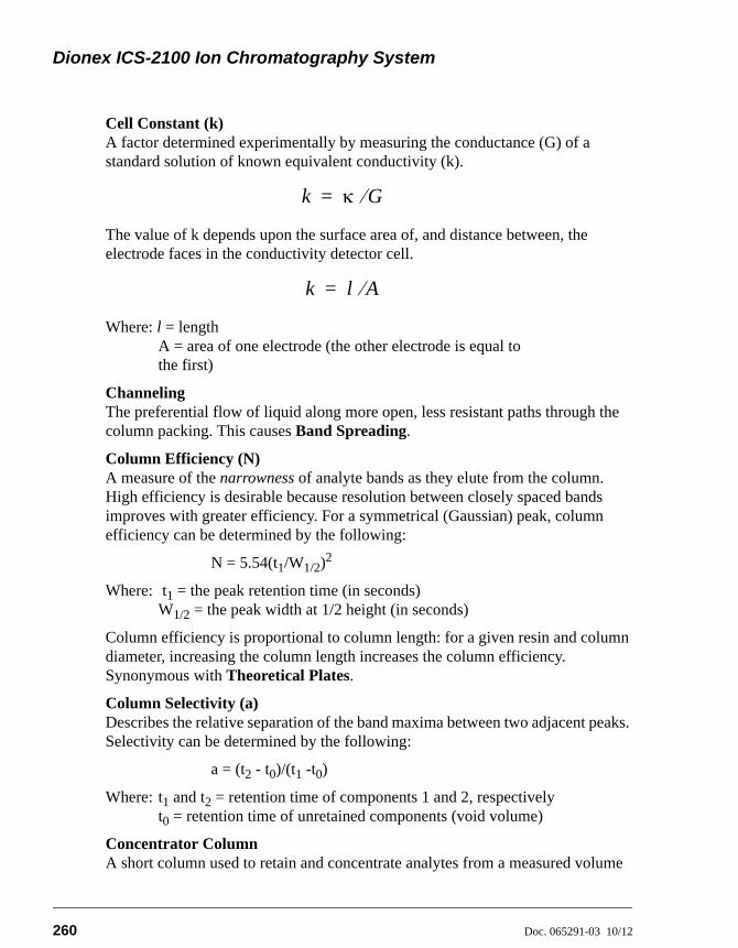
Dionex ICS-2100 Ion Chromatography System
260 Doc. 065291-03 10/12
Cell Constant (k)A factor determined experimentally by measuring the conductance (G) of a standard solution of known equivalent conductivity (k).
The value of k depends upon the surface area of, and distance between, the electrode faces in the conductivity detector cell.
Where: l = lengthA = area of one electrode (the other electrode is equal tothe first)
ChannelingThe preferential flow of liquid along more open, less resistant paths through the column packing. This causes Band Spreading.
Column Efficiency (N)A measure of the narrowness of analyte bands as they elute from the column. High efficiency is desirable because resolution between closely spaced bands improves with greater efficiency. For a symmetrical (Gaussian) peak, column efficiency can be determined by the following:
N = 5.54(t1/W1/2)2
Where: t1 = the peak retention time (in seconds)W1/2 = the peak width at 1/2 height (in seconds)
Column efficiency is proportional to column length: for a given resin and column diameter, increasing the column length increases the column efficiency. Synonymous with Theoretical Plates.
Column Selectivity (a)Describes the relative separation of the band maxima between two adjacent peaks. Selectivity can be determined by the following:
a = (t2 - t0)/(t1 -t0)
Where: t1 and t2 = retention time of components 1 and 2, respectivelyt0 = retention time of unretained components (void volume)
Concentrator ColumnA short column used to retain and concentrate analytes from a measured volume
k G=
k l A=
F • Glossary
Doc. 065291-03 10/12 261
of relatively clean sample. This allows large volumes of sample to be injected, lowering concentration detection limits.
ConductivityA measure of the ease with which electrical current flows through a liquid contained between two opposite charged electrodes. Conductivity is a characteristic of ions in solution. Units are siemens.
CounterionIons carrying a charge opposite that of the sample ions (e.g., Na+) may be the counterion of a Cl- analyte. These ions preserve electrical neutrality in solution.
% CrosslinkDivinylbenzene content in a polystyrene/divinylbenzene (PS-DVB) resin; this contributes to the mechanical strength of the resin and determines chromatographic properties.
Equivalent Conductivity ()The contribution of an ionic species to the total conductivity of a solution as measured in a standard cell having electrodes 1 cm2 in area and exactly 1 cm apart.
Guard ColumnA small column that prevents poisoning of the separator column by sorbing organic contaminants and removing particulates. It is filled with the same packing as the separator column. Synonymous with Pre-Column.
HETP (H)Height Equivalent to a Theoretical Plate. A measure of column efficiency which allows comparison between columns of different lengths.
HETP = H = L/N
Where: L = the column length (in mm)N = the number of theoretical plates
Ion-Exchange CapacityThe number of active ion exchange sites in a given weight or volume of resin; this is usually expressed in meq/g or meq/mL.
Ion-Exchange ResinAn insoluble polymer matrix containing fixed-charge exchange sites (anionic or cationic). IC resins are formed into small spherical particles (beads).
Dionex ICS-2100 Ion Chromatography System
262 Doc. 065291-03 10/12
PackingThe material that fills a chromatographic column; usually a resin or silica-based material.
Pellicular ResinA resin with a solid, nonporous core coated with a thin layer of more porous material. The exchange sites of pellicular ion exchange resins are located only on the surface layer of the bead. These resins have a low ion-exchange capacity.
Pre-ColumnSynonymous with Guard Column.
RegenerantA dilute acid or base that converts ion exchange sites in a MicroMembrane Suppressor back to the form that suppresses the eluent conductivity.
ResinSee Ion-Exchange Resin.
Resolution (R)A measure of the separation between two sample components. This is expressed as the ratio of the distance between the two peak maxima to the mean value of the peak width at the baseline.
R = 2(t2 - t1)/(W2 + W1)
Where: t1 and t2 =the retention times of components 1 and 2,respectivelyW1 and W1 = the baseline width of peaks 1 and 2,respectively (measured in the same units as the retentiontime)
R is proportional to the square root of efficiency (N). A value of R = 1.5 represents “baseline separation” of the two peaks.
Retention TimeThe time from injection to peak maximum; the basis for identification of a species in chromatographic analysis.
Separator ColumnThe column used to perform a chromatographic separation; also called an analytical column.
F • Glossary
Doc. 065291-03 10/12 263
Siemens (S)Unit measure of conductance; the reciprocal of the electrical resistance of a solution.
SuppressorA device used to minimize eluent conductivity and convert sample species to a common form, thus increasing detection sensitivity.
Temperature CoefficientThe percent of change in the conductivity of a solution with a 1 oC change in temperature. Every solution has a characteristic temperature coefficient which is determined experimentally.
Theoretical Plates (N)See Column Efficiency.
Void Volume (V0)The volume occupied by the eluent in a packed column. This volume includes the volume between the injection valve and the column, as well as between the column and the detector cell. Unretained components are eluted in the void volume.
Dionex ICS-2100 Ion Chromatography System
264 Doc. 065291-03 10/12
Doc. 065291-03 10/12 Index-1
Symbols% Offset (analog out), 233
AAdjusting the contrast, 12, 207Air particulate samples, 61Alarm conditions, 74 – 85
See also Error messagesAmbient temperature, 96Analog output, 231, 233, 240
% Offset, 233Configuring, 233, 249Connections, 249Connector, 21Full-scale, 233Range, 233
Analog-to-digital controller, 249Anion separations, 37, 60Application Wizard, 67AS Autosampler, 62
Connections for stand-alone operation, 246Enabling injection valve control, 248Maintenance, yearly, 69Method for stand-alone operation, 250Sample injection, 64Schedule for stand-alone operation, 250Time Function Out screen, 248
AS-DV Autosampler, 62Maintenance, yearly, 69Sample injection, 64
AS-HV Autosampler, 63Atlas Electrolytic Suppressor, 20
See also SuppressorAudit Trail
Error messages, 71Icons, 71
AutosamplerLoading samples with, 64See also AS AutosamplerSee also AS-DV Autosampler
Autosampler Control panel, 31Autosampler specifications
Automated dilution, 203Automation, 203Automation flexibility, 203Online filtration, 203Online sample degassing, 203Semiautomated system qualification, 203Sequential/Simultaneous injection, 203
Autozero, 59, 66, 215Auxiliary power supply, 42
Connection to system, 16Home page control, 214Specifications, 202
Auxiliary valve, 4, 19, 44, 62Applications, 44Configuration, 62Does not switch position, 83Installation instructions, 44Leaking, 87Maintenance, yearly, 69Passages blocked, 93Rebuilding, 114Reordering, 252Replacing the mechanical part (pod), 114 –
115Troubleshooting, 83
BBackground conductivity
High, 95Offsetting, 59, 215, 217
Index
Dionex ICS-2100 Ion Chromatography System
Index-2 Doc. 065291-03 10/12
BacklightTime-out, 235
Backpressure, 36Restriction in plumbing, 109Troubleshooting, 92
Backpressure coil, 40Backpressure, low
How to increase, 40Bar, 224Baseline
Drift, 96Noise, 96, 232Stability, 46Zeroing, 215
Batch processing, 50Blockages
Liquid lines, 82, 109Busy page, 235
CCables
Power cord, 142Calibration, 99
Conductivity cell, 103Flow rate, 106Vacuum degas assembly, 108
Carbonate eluent, 23, 37, 41Carbonate/bicarbonate eluent, 23, 37, 41Cation separations, 37, 60Cell
See Conductivity cellCell calibration, 103Cell heater, 215Check valves
Cleaning procedure, 118 – 119Replacement procedure, 118 – 119
Chromatogram, 3Zeroing the baseline, 215
Chromeleon, 30Alarm conditions, 74Application Wizard, 67Audit Trail, 71
Audit Trail error messages, 71Commands, 66Control panel, 65Degas options, 97Error messages, 74Interface, 30Menu, 65Overview, 30Panel tabset, 30Programs, 64Quantification method, 68Starting, 52Timebase, 30Toolbars, 65Using the touch screen with Chromeleon,
210Wellness panel, 99
Chromeleon ServerStarting, 52
Chromeleon Server Monitor, 52Column heater, 20, 45
Home page control, 214Replacement procedure, 131Specifications, 201
Column heater alarmsColumn heater exceeds safe temperature,
75Column heater open circuit, 76Column heater short circuit, 76
Columns, 20Cleaning, 257Contaminated, 94Damage from IPA, 142Storing, 256
Component panel, 18Concentration, 227
Upper limits, 79, 227See also EGC
Conductivity, 215Causes of high conductivity, 257Changing the display, 235Offset, 215, 235Temperature effect, 46Total, 215, 235
Index
Doc. 065291-03 10/12 Index-3
Conductivity cell, 19 – 20, 46Calibrating, 103Calibration constant, 128High cell output, 95Leaking, 87No response, 94Replacement procedure, 127Setting the temperature, 215Volume, 46
Conductivity cell specificationsActive volume, 200Cell body, 200Chemical compatibility, 200Electrodes, 200Maximum pressure, 200Temperature, 200
Conductivity polarity, 232Contacting Thermo Fisher Scientific, 8Contamination
Column, 92, 94Eluents, 93Sample, 94Standard, 93
Continuously Regenerated Trap ColumnSee CR-TC
Control panel (Chromeleon), 30, 65Autosampler, 31Sequence Control, 31Status, 31
CR-TC, 40Connector, 16Controlling automatically, 229Controlling manually, 229Home page control, 214Replacement, 165
CR-TC alarmsCR-TC over current error, 76CR-TC stopped for zero flow rate, 77
Current, 230
DDaily maintenance, 68
DataBacking up, 256Deleting, 256Filtering, 232Saving, 65 – 66
Data acquisition, 65Data analysis description, 3Data rise time, 231 – 232Decibel level, 195Default panel tabset, 31Degas tubing assembly
See Vacuum degas assemblyDegas calibration failed alarm, 77Degas tubing assembly, eluent generator, 37, 39Degassing eluents, 32Detection description, 3Detector controls on Home page, 215
See also Conductivity cellDetector page, 231
Setting analog out options, 233Setting the data rise time, 232
Detector specificationsAuto offset, 200Calibration, 200Cell drive, 200Control and data evaluation, 200Linearity, 200Range, 200Resolution, 200Temperature compensation, 200
Diagnostic pages, 236Diagnostics, 99Dimensions, 195Dionex, 52Direct software control, 31Drip tray, 19DS6 Heated Conductivity Cell
See Conductivity cellDuty cycle, 33, 225
Dionex ICS-2100 Ion Chromatography System
Index-4 Doc. 065291-03 10/12
EEGC, 16
Backpressure requirement, 40, 43Concentration ranges, 38Concentration upper limits, 79, 227EGC-1 connector, 16, 148, 156EGC-2 connector, 16Eluent types, 37Entering the serial number, 226Expiration date, 228Home page controls, 214Life remaining percentage, 228Service area, 17See also Eluent generator
EGC alarmsEGC board not present, 77EGC-1 calibration error, 78EGC-1 disconnected error, 78EGC-1 invalid concentration vs. flow rate
error, 79EGC-1 invalid flow rate error, 79EGC-1 over current, 79EGC-1 over voltage, 80
EGC CO3 MixerDescription, 37, 41Flow schematics, 23Replacement procedure, 174
EGC Resistive Load, 102EGC Verification, 102EGC-1 connector, 16, 148, 156EGC-2 connector, 16Elapsed time, 215, 217Electrical specifications
Fuses, 195Main power, 195
Electrolysis gasesPurging from eluent, 40, 43
Electrolytic pH modiferSee EPM Electrolytic pH Modifier
EluentAqueous, 69, 89Concentration, 227Degassing, 32
Delivery process, 2Filtering, 54See also Eluent generator
Eluent bottleSee Eluent reservoir
Eluent concentration, 38Eluent generator, 16, 37
Backpressure, 43Controlling automatically, 228Controlling manually, 228Degas tubing assembly, 37, 39EGC holder, 39EGC replacement procedure, 143EGC types, 37Electrolysis gases, 40, 43Eluent concentration ranges, 38Setting the concentration, 227Specifications, 198See also EGC
Eluent Generator page, 226Eluent level, 54, 213Eluent reservoir
Connecting, 56Monitoring liquid level in, 54, 213
Eluent valve, 20, 225Replacing, 135
EluGen cartridgeSee EGC
End-line filterSee Filter, end-line
Environmental specifications, 196EPM Electrolytic pH Modifier, 16, 40 – 41
Replacement procedure, 169Equilibration time, 59Error messages, 74 – 80, 82 – 85
Audit Trail description, 71Auxiliary power supply disconnected, 74Auxiliary power supply over current, 74 –
75Auxiliary power supply over voltage, 75Auxiliary power supply stopped for zero
flow rate, 75Column heater exceeds safe temperature,
75
Index
Doc. 065291-03 10/12 Index-5
Column heater open circuit, 76Column heater short circuit, 76CR-TC over current error, 76CR-TC stopped for zero flow rate, 77Degas calibration failed, 77EGC board not present, 77EGC-1 calibration error, 78EGC-1 disconnected error, 78EGC-1 invalid concentration vs. flow rate
error, 79EGC-1 invalid flow rate error, 79EGC-1 over current, 79EGC-1 over voltage, 80Hardware not present, 80Leak sensor wet, 80Load/inject valve error, 81Option not installed, 81Pump motor lost control, 82Pump over pressure, 82Pump pressure hardware error, 82Pump stopped due to lost USB
communication, 83Pump under pressure, 83Second valve error, 83Suppressor not connected, 84Suppressor over current, 84Suppressor over power, 85Suppressor stopped for zero flow rate, 85
FFilter, end-line
Bacterial contamination, 69, 89Dirty or clogged, 69, 89Installation, 54
Filtering data, 232Fittings
Leaking, 86Replacing, 113Requirements, 113
Flow descriptionCarbonate eluent generation, 29
Carbonate/bicarbonate eluent generation, 27
KOH, LiOH, MSA,NaOH eluent generation, 25
Flow rate, 19, 196, 213Calibration, 106Troubleshooting, 90
Flow schematicsCarbonate eluent generation, 28
Front panel, 11See also Touch screen
Full-scale analog output, 233Fuses
Replacement procedure, 142Requirements, 195
GGas separator waste tube, 37Ghosting, 93Guard column, 20
HHardware not present error, 80Heater, column, 45
See also Column heaterHigh pressure alarm, 82Home page, 12, 207, 212, 214 – 216
Column Heater control, 214Detector controls, 215EGC controls, 214Injection valve controls, 215Pump controls, 212
Humidity, operating, 196
IInformation page, 234Injecting samples, 62
Via autosampler, 64Via syringe, 63
Dionex ICS-2100 Ion Chromatography System
Index-6 Doc. 065291-03 10/12
Via vacuum syringe, 64Injection port, 11
Injecting via syringe, 63Injection valve, 19, 42
Controlling with a Dionex AS, 248Home page controls, 215Leaking, 87Passages blocked, 93Plumbing connections, 43Rebuilding, 114Specifications, 201Troubleshooting, 81
Input/Output page, 236, 248Installation
Analog output connection, 249Priming, 138, 140Stand-alone operation setup, 246 – 247TTL and relay connections, 239 – 240
Installed options, 234Inverted edge TTL input control, 244Inverted peaks, 232Inverted pulse TTL input control, 244Ion chromatography overview, 1Ion exchange, 3IonPac ATC-HC Trap Column, 40IonPac CTC-1 Trap Column, 40Isopropyl alcohol, 141 – 142
KKOH EGC, 37
LLCD screen, 11 – 12, 207
Specifications, 196See also Touch screen
Leak sensor, 19Leak sensor wet alarm, 80Replacement, 137
LeaksAuxiliary valve, 87
Cell, 87Fittings, 86Injection valve, 87Liquid, 86Pressure transducer, 87Pump check valve, 86Pump head, 86Pump head waste valve, 87Pump piston seal, 86Suppressor, 87
LED, 196Linearity requirements, 200LiOH EGC, 37Liquid leaks, 86
See also LeaksLithium hydroxide eluent, 37Load/inject valve alarm, 81Loading samples, 62Local Mode, 216Locked Remote mode, 210Loop
See Sample loop
MMain power receptacle, 22Maintenance, 68
Daily, 68Ongoing, 68Weekly, 68Yearly, 69
Manual sample processing, 50Methanesulfonic acid eluent, 37MicroMembrane Suppressor, 20
See also SuppressorModule Setup page, 235Moduleware, 71, 234MPa, 224MSA EGC, 37
Index
Doc. 065291-03 10/12 Index-7
NNaOH EGC, 37Nitrite in samples, 61Noise, baseline, 232Normal edge TTL input control, 243Normal pulse TTL input control, 244
OOffset conductivity, 235Offset percentage (analog out), 233Offsetting background conductivity, 59, 215Operating features, 11Operating humidity, 196Operating ranges
Cell heater, 19, 215Column heater, 20, 214Eluent concentration, 79, 227Flow rate, 19, 213
Operating temperature, 196Operation
Equilibration time, 59Overview, 49Priming, 57, 140 – 141Reservoir setup, 54Sample preparation, 60Sample processing, 50Setting operating conditions, 58Starting Chromeleon, 52
Operational status verification, 59Option not installed error, 81Options installed, 234Oven
See Column heaterOverview of system, 4
PPanel tabset, 30
How to display, 31Panels
Chromeleon Control panel, 65
Chromeleon Wellness panel, 99Component panel, 18
ParametersChromeleon operating commands, 66
Peak ghosting, 93Peak height
Effect of rise time on, 232Reproducibility, 46Troubleshooting, 94
Peak shape, 232Peak width, 232Peaks
Effect of rise time on, 232Extraneous (ghosting), 93Inverted, 232Reversed, 232 – 233
PEEKConductivity cell body, 46
PGM fileSee Programs
pH modiferSee EPM Electrolytic pH Modifier
Physical specificationsDecibel level, 195Dimensions, 195Weight, 195
Piston sealsReplacement procedure, 120 – 121
PistonsReplacement procedure, 124
Plot offset, 217Plot page, 216 – 217
Elapsed time, 217Plot offset, 217Range, 217
Plotting detector output, 217Plumbing
Injection valve, 115Replacing tubing and fittings, 113Troubleshooting, 109
PolaritySelecting the conductivity polarity, 232
Potassium carbonate eluent, 41Potassium hydroxide eluent, 37
Dionex ICS-2100 Ion Chromatography System
Index-8 Doc. 065291-03 10/12
Power cord, 142Power receptacle, 22Power requirements, 195Pressure
Home page display, 212Limit, 83, 212, 223System, 83, 223Unit (selecting), 223
Pressure transducer, 19, 36Leaking, 87System backpressure, 36
Prime button, 213Priming, 57, 138, 140 – 141
Pump is out of prime, 89With a syringe, 138With isopropyl alcohol, 141With the Prime button, 140
Priming valveOpening, 34O-ring replacement procedure, 125
Printing, 255Problems
See TroubleshootingProcessing samples, 50, 65 – 66
Automatically (batch), 50, 66 – 67Manually, 50, 65
Product warranty, 99, 114 – 115Programmed software control, 31Programs (Chromeleon), 31
Controlling an autosampler, 64PSI, 224Pulse damper, 25, 27, 29, 36Pump, 34
Flow rate, 19, 213Home page controls, 212Leaks, 86Over pressure alarm, 82Primary pump head, 34Priming, 57, 138Priming problems, 88Secondary pump head, 35Selecting the pressure unit, 223Setting pressure limits, 223Stopped due to lost USB communication,
83Troubleshooting, 90Under pressure alarm, 83
Pump check valve leaking, 86Pump degas
See Vacuum degas assemblyPump head waste valve
Leaking, 87O-ring replacement procedure, 125
Pump heads, 118Pump motor lost control alarm, 82Pump page, 223
Changing the pressure unit, 223Setting degas parameters, 224Setting pressure limits, 223
Pump pressure hardware error, 82Pump priming valve
O-ring replacement procedure, 125Pump specifications
Construction, 196Delay volume, 196Eluent bottle pressure, 196Eluent generation, 196Flow accuracy, 196Flow precision, 196Flow rate, 196Gradient capabilities, 196Operating pressure, 196Pressure ripple, 196Type, 196Vacuum degasser, 196
QQuantification method, 68
RRange, 217, 233Rear panel, 21
Analog output connector, 21Power receptacle, 22
Index
Doc. 065291-03 10/12 Index-9
USB connections, 21Rebuilding the auxiliary valve, 114Rebuilding the injection valve, 114Recorders
Analog output setting, 233Relay connections
Rear panel connector, 22, 239Relay outputs
Controlling, 245Voltage and current specifications, 240
Remote Mode, 216Reordering information, 251Reproducibility, 46Reservoir
Connecting, 56Monitoring liquid level in, 54
Restriction in liquid lines, 82, 109Retention time
Adjusting, 255Moving, 255Troubleshooting, 94
Reverse peaks, 232Rise time, 232Running samples, 65
See also Processing samples
SSafety messages, 6Sample loop, 19, 42
Changing, 113Injecting, 43Injection valve connections, 43, 114Loading, 42Reordering, 252
Sample processing, 50, 65 – 66Batch, 50, 66Manual, 50, 65With Chromeleon, 65 – 66
SamplesCollecting and storing, 60Diluting, 61Filtering, 60
Injecting, 62, 64Loading, 62Pretreating, 61
Saving data, 65 – 66Seal replacement, 121Second valve
Troubleshooting, 83Second valve error, 83Selectivity
Troubleshooting, 94Self-Regenerating Suppressor, 20
See also SuppressorSeparation process, 3Separator column, 20Sequence Control panel, 31Sequence Wizard, 68Serial number
EluGen cartridge, 226Server Configuration program
Starting, 52Service chase, 16, 20Service procedures, 119
Check valve cleaning, 118 – 119Check valve replacement, 118Conductivity cell replacement, 127CR-TC replacement, 165EGC CO3 Mixer replacement, 174EGC holder replacement, 185Eluent generator cartridge replacement,
143EPM replacement, 169Fuse replacement, 142Injection valve rebuilding, 114Isolation of liquid lines restriction, 109Leak sensor replacement, 137Piston replacement, 124Piston seal replacement, 120Priming valve O-ring replacement, 125Rebuilding the auxiliary valve, 114Rebuilding the injection valve, 114Replacing tubing and fittings, 113Suppressor replacement, 130Tubing and fittings replacement, 113Waste valve O-ring replacement, 125
Dionex ICS-2100 Ion Chromatography System
Index-10 Doc. 065291-03 10/12
Signal-to-noise ratio, 232Sodium hydroxide eluent, 37Software control, 30
Modes of, 31Software specifications
Application templates, 204Automated procedure wizards, 204Automation support for third-party
vendors, 204Customizable system control panels, 204Customized reporting, 205Daily Audit Trail, 204Multiple network control, 205Network failure protection, 205Power failure protection, 204Sample Audit Trail, 204Sequential injection, 204Storage of calibration settings, 205System status virtual channels, 204System trigger commands and
conditionals, 204System Wellness and Predictive
Performance, 204Virtual column simulator, 204
SpecificationsAutosampler, 203Column heater, 201Conductivity cell, 200Detector, 200Electrical, 195Eluent generator, 198Environmental, 196Injection valve, 201LCD touch screen, 196Physical, 195Pump, 196Supressors, 202System software, 204Vacuum degas assembly, 201
Stand-alone operation, 246 – 250Analog output connection, 249AS setup, 248, 250Example connections, 247TTL and relay connections, 246
StandardsWhen to remake, 255 – 256
Status Control panel, 31Status page, 216, 218Sulfite in samples, 61Suppression description, 3Suppressor
Controlling the current to, 230Description, 20, 46Gas separator waste tube, 37Leaking, 87Replacement procedure, 130Selecting the type, 230
Suppressor alarmsSuppressor not connected, 84Suppressor over current, 84Suppressor over power, 85Suppressor stopped for zero flow rate, 85
Suppressor page, 230Supressor specifications
Chemical suppression, 202Displacement chemical regeneration, 202Electrolytic suppression, 202Sequential suppression for anions, 202Suppression capacity, 202Suppressor wear parts, 202Void volume, 202
Syringe injection, 63Vacuum, 64
SystemShutdown, 256Status, 59
System backpressure, 36System components
Descriptions, 32System overview, 4System Wellness, 31
TTechnical Support, 8, 71, 99Temperature
Cell heater, 46, 215
Index
Doc. 065291-03 10/12 Index-11
Column heater, 20, 45, 214Minimizing the effect of variations, 46
Temperature compensation, 46Temperature, operating, 196Thermo Fisher Scientific
Contacting, 8Thermo Fisher Scientific Technical Support, 8, 71, 99Timebase, 30Time-out (screen), 235Top cover, 16Total conductivity, 215, 235Touch screen, 11, 207
Adjusting the contrast, 12, 207Number keypad, 13, 208Operation, 12, 207Specifications, 196Time-out, 235Using with Chromeleon, 210
Touch screen pagesBusy page, 235Detector page, 231Diagnostic pages, 236Eluent Generator page, 226Home page, 12, 207, 212, 215 – 216Information page, 234Input/Output page, 236, 248Module Setup page, 235Overview, 211Plot page, 216 – 217Pump page, 223Status page, 216, 218Suppressor page, 230
Troubleshooting, 71Alarm conditions, 74Baseline noise or drift, 96Calibrations, 99Diagnostics, 99Error messages, 74Excessive backpressure, 92Flow rate, 90High cell output, 95Liquid leaks, 86No cell response, 94
Peak ghosting, 93Peak height, 94Pump, 88 – 90Retention time, 94Selectivity, 94Vacuum degas assembly, 97
TTL and relay connector, 239Connection instructions, 240Pin assignments, 239
TTL inputsAssigning functions to, 243, 248Control type, 248Default function assignments, 240Rear panel connector, 22
TTL outputsControlling, 245Rear panel connector, 22
TubingReplacing, 113Requirements, 113Routing clips, 22
Tubing connectionsIsolating a restriction, 82, 109
UUSB connections, 21
VVacuum degas assembly, 32
Calibration, 108Components, 32Fails to run, 97Setting operating parameters, 224Specifications, 201Troubleshooting, 88
ValveSee Auxiliary valveSee Eluent valveSee Injection valveSee Waste valve
Dionex ICS-2100 Ion Chromatography System
Index-12 Doc. 065291-03 10/12
Version number, 234
WWarranty, voiding, 99, 114 – 115Waste container, 185Waste lines
Blocked, 86Gas separator waste tube, 37
Waste valve, 35Opening, 35, 120O-ring replacement procedure, 125
Water samples, 61Weekly maintenance, 68Weight, 195Wellness, 31Wellness panel, 99
YYearly maintenance, 69
ZZero position (analog out), 233Zeroing the baseline, 215