digital videocassette recorder - concordia.ca · caution precautions you are cautioned that any...
TRANSCRIPT
3-065-956-11(1)
DigitalVideocassetteRecorderOperating Instructions-
Mode d'emploi ____
DSR-11© 2000 Sony Corporation

WARNING
To prevent fire or shock hazard, do notexpose the unit to rain or moisture.
CAUTIONRISK OF ELECTRIC SHOCK
DO NOT OPEN
Owner's record
The model number is located at the rear and front of the unitand the serial number on the rear Record the serial numberin the space provided below Refer to these numberswhenever you call upon your Sony dealer regarding thisproduct
Model No DSR-11 Serial No. _______________
CAUTION TO REDUCE THE RISK OF ELECTRIC SHOCK,
DO NOT REMOVE COVER (OR BACK)
NO USER SERVICEABLE PARTS INSIDE
REFER SERVICING TO QUALIFIED SERVICE PERSONNEL
For customers in the U.S.A.I f you have any questions about this product, you may
call: Sony's Business Information Center (BIC) at 1-800-686-SONY (7669)
or Write to: Sony Customer Information Services Center6900-29 Daniels Parkway, PMB 330 FortMyers, Florida 33912
This symbol is intended to alert the user to thepresence of uninsulated "dangerous voltage"within the product's enclosure that may be ofsufficient magnitude to constitute a risk ofelectric shock to persons
This symbol is intended to alert the user to thepresence of important operating andmaintenance (servicing) instructions in theliterature accompanying the appliance
Trade Name.ModelResponsible Party:Address.
Telephone Number
Declaration of Conformity
SONYDSR-11Sony Electronics Inc1 Sony Drive, Park Ridge,NJ 07656 U S A201-930-6972
The AC adaptor must be changed only at qualified serviceshop
The nameplate of the AC adaptor is located on its bottom
For customers in EuropeThis product with the CE marking complies with both theEMC Directive (89/336/EEC) and the Low Voltage Directive(73/23/EEC) issued by the Commission of the EuropeanCommunityCompliance with these directives implies conformity to thefollowing European standards• EN60065 Product Safety (supplied AC adaptor)• EN55103-1 Electromagnetic Interference (Emission)• EN55103-2 Electromagnetic Susceptibility (Immunity)This product is intended for use in the followingElectromagnetic Environments)E1 (residential), E2 (commercial and light industrial), E3(urban outdoors) and E4 (controlled EMC environment, exTV studio)
For the customers in the NetherlandsVoor de klanten in Nederland
This device complies with Part 15 of the FCC RulesOperation is subject to the following two conditions (1)This device may not cause harmful interference, and (2)this device must accept any interference received,including interference that may cause undesiredoperation
BI) dit product zijn batterijengeleverd Wanneer deze leegzi]n, moet u ze met weggooienmaar inleveren als KCA
2

CAUTION Precautions
You are cautioned that any changes or modifications notexpressly approved in this manual could void your authorityto operate this equipment.
NoteThis equipment has been tested and found to comply withthe limits for a Class B digital device, pursuant to Part 15 ofthe FCC Rules. These limits are designed to providereasonable protection against harmful interference in aresidential installation. This equipment generates, uses, andcan radiate radio frequency energy and, if not installed andused in accordance with the instructions, may cause harmfulinterference to radio communications. However, there is noguarantee that interference will not occur in a particularinstallation. If this equipment does cause harmfulinterference to radio or television reception, which can bedetermined by turning the equipment off and on, the user isencouraged to try to correct the interference by one or moreof the following measures:• Reorient or relocate the receiving antenna.• Increase the separation between the equipment and
receiver.• Connect the equipment into an outlet on a circuit different
from that to which the receiver is connected.• Consult the dealer or an experienced radio/TV technician
for help.
For customers in the U.S.A. and CANADA
CAUTION
TO PREVENT ELECTRIC SHOCK, MATCH WIDE BLADEOF PLUG TO WIDE SLOT, FULLY INSERT.
Caution
Television programs, films, video tapes and other materialsmay be copyrighted. Unauthorized recording of such materialmay be contrary to the provisions of the copyright laws. Also,use of this recorder with cable television transmission mayrequire authorization from the cable television transmissionand/or program owner.
• Do not damage the power cord and AC adaptor.•Use only the supplied power cord and supplied AC
adaptor.• Do not use the unit in an environment that is subjectto excessive soot, steam, humidity or dust.
You can use this equipment in any country or area withthe AC power adaptor supplied with this unit within100 V to 240 V AC, 50/60 Hz.Use a commercially available AC plug adaptor [a], ifnecessary, depending on the design of the wall outletlb].
The AC adaptor is not intended to be serviced. Shouldthe product cease to function in its intended manner, itshould be returned to the manufacturer or be discarded.
On installingThe unit is equipped with ventilation holes on the rear.Do not block or place anything near these holes, orinternal heat build-up may occur, causing damage tothe unit.
On repacking and shippingSave the original shipping carton and packing material;they will come in handy if you ever have to ship yourunit. For maximum protection, repack your unit as itwas originally packed at the factory, and take care notto impart violent shocks in transit.
3

Overview Features ...............................................................DVCAM Format....................................................Other Features ......................................................
Location and Function of Parts ..........................Front Panel ...........................................................Rear Panel ............................................................Supplied Remote Commander .............................
667
8
8
11
13
Playback andRecording
Notes on Video Cassettes ...................................Preparations .........................................................
Power Preparations................................................Inserting/Ejecting Cassettes ..................................Notes on Recording/Playback ...............................
Playback ................................................................Connections for Playback......................................Settings for Playback.............................................Playback Procedure ...............................................Playback Functions ...............................................
Recording .............................................................Connections for Recording....................................Settings for Recording ...........................................Recording Procedure .............................................
Installing the Unit Vertically ................................
151717
17
192020
2 3
2 4
25
3434
37
3 9
40
Adjusting andSetting ThroughMenus
Operating the Menus .....................................Menu Organization .........................................Menu Contents ...............................................
4142
43
4 Table of Contents

Maintenance Troubleshooting..................................................Alarm Messages ..................................................Notes on Use .......................................................
50
51
52
Compatibility of DVCAM and DV Format..........Specifications......................................................Glossary..............................................................Index.....................................................................
55
58
60
61
Table of Contents 5
Chapter 1Overview
The DSR-11 is a '/4-inch digital video cassette recorderthat uses the DVCAM™ digital recording format. Thissystem achieves stable, superb picture quality bydigitally processing video signals that are separatedinto color difference signals and luminance signals(component video).With a compact, lightweight and space-saving case,the unit can be installed vertically and is equipped withan analog interface as well as a digital interfaceenabling connection to a digital device such as acomputer.
The DSR-11 's main features are described below.
DVCAM Format
DVCAM is based on the consumer DV format, whichuses the 4:1:1 component digital format (NTSC) or the4:2:0 format (PAL), and provides a '/4-inch digitalrecording format for professional use.
High picture quality, high stabilityVideo signals are separated into color differencesignals and luminance signals, which are encoded andcompressed to one-fifth size before being recorded toensure stable and superb picture quality.Because the recording is digital, multi-generationdigital dubbing can be performed with virtually nodeterioration of quality.
Wide track pitchThe recording track pitch is 15 urn, fully 50 percentwider than the DV format's 10-um track pitch. Thanksto this feature, the DVCAM format sufficiently meetsthe reliability and precision requirements ofprofessional editing.
High-quality PCM digital audioPCM recording makes for a wide dynamic range and ahigh signal-to-noise ratio, thereby enhancing soundquality.There are two recording modes: 2-channel mode (48-kHz sampling and 16-bit linear code), which offerssound quality equivalent to the DAT (Digital AudioTape) format, or 4-channel mode (32-kHz samplingand 12-bit nonlinear code).
DV format compatibilityA DV cassette recorded on a DV-format VCR can beplayed back on the unit (SP mode only). The unit canalso record in DV format (SP mode only). (Recording/playing back an image in LP mode is not available.)
6 Chapter 1 Overview
NTSC/PAL systems compatibleThe unit is compatible with NTSC and PAL systems.When inputting the signals to the DV IN/OUTconnector or playing back a tape, the color system ofsignals is detected automatically. The color systemselect switch on the unit allows input of analog videosignals in either color system. This compatibilityallows you to record (download) or play back (upload)both NTSC and PAL formatted signals with yourVCR, computer, or other equipment.However, the unit cannot convert the color system ofthe signals.
Choice of two cassette sizesThe unit can use both standard-size and mini-sizeDVCAM or DV cassettes.• According to cassette size, the position of the reeldrive plate changes automatically.
• The maximum recording/playback times are 184minutes for standard size cassettes and 40 minutes formini-size cassettes (DVCAM format).
Remote control
The unit can be operated by remote control from aCONTROL-S system remote control unit, the DSRM-20 (not supplied).
High-speed search function
When you use an editing controller or the optionalremote control unit (DSRM-20), the unit has a picturesearch function that allows you to view color picture atplayback speeds up to 14 times (NTSC) or up to 17times (PAL) normal speed in forward and reversedirections. You can also search frame-by-frame in jogmode.You can also hear playback audio.
Jog audio function
If you use the optional remote control unit DSRM-20,audio can be monitored at various playback speedswhen in jog mode.
Other Features
Compact and can be installed vertically
The unit is compact and can be installed vertically.With non-linear editing system, you can save space byinstalling it vertically beside your computer.
Menu system for functionality andoperation settings
The unit provides a menu system to make its variousfunctions easier to use and set up.
Superimposition function
Time code, operation mode indications, menus, errormessages, and other text data can be superimposed andoutput in analog video signals.
Easy maintenance functions
• Self-diagnostics/alarm functions: The systemautomatically detects an invalid operation, an invalidconnection or a malfunction, and outputs adescription, a cause and a recovery method as amessage superimposed on analog video signals.
• Digital hours meter: A digital hours meter countsfour types of time data—operating time, drumrotation time, tape running time, and tape threading/unthreading. The digital hours data is displayed in themenu.
Digital slow playback
The unit has a frame memory function that allowssmooth, slow playback. This is available only at +'/3-time speed and -'/3-time speed.
Chapter 1 Overview 7

Front Panel
Cassette lid INPUT SELECT selectorTo insert/eject a cassette, open the lid.For details of usable cassettes, see "Notes on VideoCassettes " on page ] 5 (GB).
REMOTE CONTROL switchSelects whether the unit is operated from the RemoteCommander or from an optional remote control unit.
WIRELESS: The unit is operated from the RemoteCommander.
CONTROL S: The unit is operated from a remotecontrol unit (the DSRM-20, not supplied),connected to the CONTROL S jack on the rearpanel.
You can select DV, S VIDEO, or VIDEO to input thesignals.
DV: Signal input from the DV IN/OUT connectorS VIDEO: Signal input from the S VIDEO connector
on INPUT jacksVIDEO: Signal input from the VIDEO jack on
INPUT jacks
Do not change the selector setting during recording.Otherwise, noise is output to the picture and sound andthat portion will not be recorded properly.
Remote sensor
You can operate this unit from its front panelregardless of this switch setting.
8 Chapter 1 Overview
ON/STANDBY switch
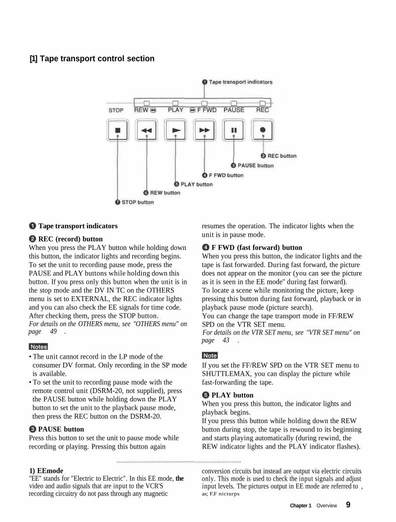
[1] Tape transport control section
Tape transport indicators
REC (record) buttonWhen you press the PLAY button while holding downthis button, the indicator lights and recording begins.To set the unit to recording pause mode, press thePAUSE and PLAY buttons while holding down thisbutton. If you press only this button when the unit is inthe stop mode and the DV IN TC on the OTHERSmenu is set to EXTERNAL, the REC indicator lightsand you can also check the EE signals for time code.After checking them, press the STOP button.For details on the OTHERS menu, see "OTHERS menu" onpage 49 .
resumes the operation. The indicator lights when theunit is in pause mode.
F FWD (fast forward) buttonWhen you press this button, the indicator lights and thetape is fast forwarded. During fast forward, the picturedoes not appear on the monitor (you can see the pictureas it is seen in the EE mode'' during fast forward).To locate a scene while monitoring the picture, keeppressing this button during fast forward, playback or inplayback pause mode (picture search).You can change the tape transport mode in FF/REWSPD on the VTR SET menu.For details on the VTR SET menu, see "VTR SET menu" onpage 43 .
• The unit cannot record in the LP mode of theconsumer DV format. Only recording in the SP modeis available.
• To set the unit to recording pause mode with theremote control unit (DSRM-20, not supplied), pressthe PAUSE button while holding down the PLAYbutton to set the unit to the playback pause mode,then press the REC button on the DSRM-20.
PAUSE buttonPress this button to set the unit to pause mode whilerecording or playing. Pressing this button again
If you set the FF/REW SPD on the VTR SET menu toSHUTTLEMAX, you can display the picture whilefast-forwarding the tape.
PLAY buttonWhen you press this button, the indicator lights andplayback begins.If you press this button while holding down the REWbutton during stop, the tape is rewound to its beginningand starts playing automatically (during rewind, theREW indicator lights and the PLAY indicator flashes).
1) EEmode"EE" stands for "Electric to Electric". In this EE mode, thevideo and audio signals that are input to the VCR'Srecording circuitry do not pass through any magnetic
conversion circuits but instead are output via electric circuitsonly. This mode is used to check the input signals and adjustinput levels. The pictures output in EE mode are referred to ,as; F.F nicturps
Chapter 1 Overview 9

Location and Function of Parts
• When the unit is playing back a part of the tape wherethe recording format has been changed between theDVCAM format and the DV format, the picture andsound may be distorted.
• The unit cannot play back a tape recorded in the LPmode of the consumer DV format.
button during stop, the tape is rewound to its beginningand starts playing automatically (during rewind, theREW indicator lights and the PLAY indicator flashes).You can change the tape transport mode in FF/REWSPD on the VTR SET menu.For details on the VTR SET menu, see "VTR SET menu" onpage 43
REW (rewind) buttonWhen you press this button, the indicator lights and thetape starts rewinding. During rewind, the picture doesnot appear on the monitor (you can see the picture as itis seen in the EE mode during rewind).To locate a scene while monitoring the picture, keeppressing this button during rewind, playback or inplayback pause mode (picture search).If you press the PLAY button while holding down this
If you set the FF/REW SPD on the VTR SET menu toSHUTTLEMAX, you can display the picture whilerewinding the tape.
STOP buttonPress this button to stop the current tape transportoperation.
[2] Indicators
POWER indicatorCAUTION indicator
indicatorDVCAM indicator
NTSC indicatorPAL indicator
NTSC PALPOWER CAUTION DVCAM
POWER indicatorLights in green when the power of this unit is on andlights in red when the unit is in the standby mode.
CAUTION indicatorFlashes when an error occurs.For details on cautions, see "Alarm Messages" on page51
(cassette) indicatorLights when a digital video cassette is loaded. Evenif the unit is in the standby mode, the indicator lightsas long as the cassette is inside of the unit. While thecassette is being ejected, the indicator flashes.
NTSC indicatorLights when:• the unit is in the EE mode, analog video signals are
input and the NTSC/PAL select switch is set toNTSC.
• the unit is in the EE mode and NTSC formattedvideo signals are input from the DV IN/OUTconnector.
• a tape that has NTSC formatted video signals isbeing played back.
For details on the VTR SET menu, see "VTR SET menu" onpage 43 (GB).
DVCAM indicator PAL indicatorLights when the unit is playing back a tape recordedin DVCAM format.When the REC MODE on the VTR SET menu is setto DVCAM, this indicator also lights duringrecording or in the EE mode.
10 Chapter 1 Overview
Lights when:• the unit is in the EE mode, analog video signals are
input and the NTSC/PAL select switch is set to PAL.• the unit is in the EE mode and PAL formatted video
signals are input from the DV IN/OUT connector. •• a tape that has PAL formatted video signals is beingplayed back.

CONTROL Sjack
RESET button DV IN/OUTconnector
LANC jack
INPUT jacks
DC IN 12Vconnector
AUTO REPEATswitch
OUTPUT jacks
NTSC/PALselect switch
Connects to other video devices that have a LANCjack. You can operate the unit from other videodevices.
i.LINK and the i.LINK logo are trademarks andindicate that this product is in agreement with IEEE1394-1995 specifications and their revisions.
• You cannot operate the ejection of a cassette from adevice connected to the LANC jack.
• The LANC jack on the unit has only LANC-Sfunctions. The unit has no LANC-M functions.
DV IN/OUT connector (4-pin)
INPUT jacksUsed to input analog video and audio signals. Toconnect a VCR equipped with S-video output, use theS VIDEO connector on the unit.
DC IN 12V connector
Used to input/output a digital signal that complies withthe i.LINK standard (Recommended cable: VMC-IL4415(A),VMC-IL4615(A)). Use when an externaldevice which you want to connect to the unit has a DVjack. If you connect the unit and the other device usingDV jacks, you can minimize deterioration of picturequality during recording, dubbing or capturing stillpictures into a personal computer by digitalprocessing. For details, refer to the instruction manualof the equipment you use.
AUTO REPEAT switchUsed to repeat the playback of all or a part of the tape.For details on the auto repeat function, see "Auto Repeat"on page 32 .
Chapter 1 Overview 11

Location and Function of Parts
OUTPUT iacksUsed to output analog video and audio signals. Toconnect a VCR equipped with S-video input, use the SVIDEO connector on the unit.
• Various text data are superimposed and output fromthe VIDEO jack or the S VIDEO connector on theOUTPUT jacks. If you want to output video signalswithout text data, carry out the following operations.- Set TITLE DISP and LABEL DISP on the CM SET
menu to OFF.• Depending on the displayed items, press the
MENU, DATA CODE, DISPLAY or SEARCHSELECT button on the Remote Commander toclear the text data on the monitor screen.
For details on text data, see "Displaying data recorded on atape" on page 25 and "Displaying various data" onpage 26 .For details on the CM SET menu, see "CM SET menu" onpage 46 .
•When the unit is in the EE mode (when the inputsignal is output as an analog signal), the subcarrier ofthe color signal is not synchronized with thehorizontal sync signal. The color of the picture or thehorizontal sync signal may be distorted depending onthe type of monitor connected to the unit.
NTSC/PAL select switchUsed to switch me color system of signals mat will oerecorded on the unit when you use analog input.To change the switch setting, turn off the power of theunit first, then use the tip of a ball-point pen or similartool to slide this switch.Before inputting NTSC or PAL formatted analog videosignals, set this switch to appropriate positionaccording to the color system of it.
• When the switch is set to PAL, the unit works as aPAL model. Therefore the time code generated by theunit while recording in the DVCAM format turns tothe non-drop frame mode. Even if an NTSCformatted signal is input from the DV IN/OUTconnector, the time code generated by the unit is non-drop frame mode as long as the switch is set to PAL,regardless of the TC FORMAT setting on theOTHERS menu. If you intend to set the unit togenerate the time code in the drop frame mode, setthe switch to NTSC.
• The color system of the signals output from the unitis the one recorded on the tape being played back.The unit cannot convert the color system of signals ofone system into that of the other. (For example:converting NTSC formatted signals into PALformatted signals is not possible) Therefore, to viewor record the signal output from the unit, you need adevice compatible with the color system of thesignals output from the unit.
• When the color system of playback signals isdifferent from the one last used on the unit, playbackpicture and sound will be distorted and time code willbe discontinuous for a short time at the beginning ofthe playback.
• If you play back a tape with both NTSC and PALcolor system recordings, the following limitationsapply.- At the point where the recorded signals format
changes, the picture may be distorted or the audionoise may be output.
- The tape transport control buttons may be disableduntil the tape running is stabilized.
• Do not change the switch setting during recording.
RESET buttonPress this button to initialize the internal clock and allmenu items. Press this button with the tip of a ball-point pen or similar tool.
• If the color system of the input signals is differentfrom that of the switch setting, both picture and soundwill be muted.
• When inputting signals to the DV IN/OUT connectoror during playback, this switch setting is invalid. Theunit detects the color system of the signalsautomatically.
CONTROL S lackConnects to a remote control unit (DSRM-20, notsupplied) for controlling this unit.
When using a CONTROL S-device, set the REMOTECONTROL switch on the front panel to CONTROL S.Otherwise, you cannot operate the unit withCONTROL S-devices.
12 Chapter 1 Overview

TC RESET button
SEARCH SELECTbuttons
Buttons forplaying at variousspeeds
PAUSE button
PLAY button -
REW button -
REC buttons
FF button
STOP button
DATA CODE button
Buttons for menu operation
On/standby switch
DISPLAY button
TC RESET button SEARCH SELECT buttonsPress this button to reset the time code to 00:00:00:00during recording or in the recording pause mode.
Press these buttons to search for scenes using thesearch function.For details on the search function, see "Searching using thesearch function" on page 29
When the command mode of a Sony device / remotecommander is set to VTR 4;• if you press this button while pointing the Remote
Commander toward a Sony device other than thisunit, the HMS counter on that machine will be resetto zero.
• if you press a counter reset button on a Sony remotecommander while pointing it toward this unit duringrecording or in the recording pause mode, the timecode will be reset to zero.
Buttons for playing at various speedsYou can play back a tape at normal speed or at a speedother than normal with these buttons.For details, see "Playing at various speeds" on page 28
PAUSE button
PLAY button
Chapter 1 Overview 13

Location and Function of Parts
Battery installationREW button
On/standby switch Push and slide the lid to open.1DISPLAY button
Press this button to see indications, such as time codeand tape remaining time, on the monitor screen.For details on displayed data, see "Displaying variousdata" on page 26
DATA CODE buttonPress this button to see the data codes (recording date/time, camera data) on the monitor screen.For details on data codes, see "Displaying data recordedon a tape " on paee 25 2 Install the two size AA (R6) batteries (supplied)
with the correct polarity.
Be sure to install thebattery from the side
Buttons for menu operationPress these buttons to operate the menu.
REC buttonsWhen you press these buttons at the same time, theREC and PLAY indicators light and recording begins.
FF button
® STOP button
3When using the Remote Commander, set theREMOTE CONTROL switch on the front panel toWIRELESS. Otherwise, you cannot operate this unitwith the Remote Commander.
Replace the lid.
Notes on batteries• Make sure that the battery orientation is correct when
inserting batteries.• Do not mix an old battery with a new one, or mix
different types of batteries.• If you will not use the Remote Commander for a longtime, remove the batteries to avoid damage frombattery leakage. If batteries have leaked, removethem, wipe the battery compartment dry and replacethe batteries with new ones.
14 Chapter 1 Overview

Chapter2Playback andRecording
Usable cassettes
Use Standard-DVCAM cassettes or Mini-DVCAM cassettes with this unit.The PDV-184 can record programs for 184 minutes (DVCAM format) /270 minutes (DV format) and the PDVM-40 can record for 40 minutes(DVCAM format) / 60 minutes (DV format).You can get the highest quality pictures with this digital videocassetterecorder using DVCAM cassettes. You may not be able to get as goodquality with other cassettes. We recommend using DVCAM cassettes sothat you can record your one-time events in the highest quality.
DVCAM cassette
Chapter 2 Playback and Recording 15
Notes on Video Cassettes
Cassette memory
Cassette memory is an optional feature that is mounted on some StandardDVCAM/DV cassettes and Mini DVCAM/Mini DV cassettes. When yourecord a program, the recording date and time, and the programs' positionon the tape are stored in the cassette memory so that you can quicklylocate the program later on. CPHGK indicates that you can use thecassettes to store up to 16 kbits of data. On this unit, you can use cassetteson which up to 16 kbits of data can be stored.
To save a recording
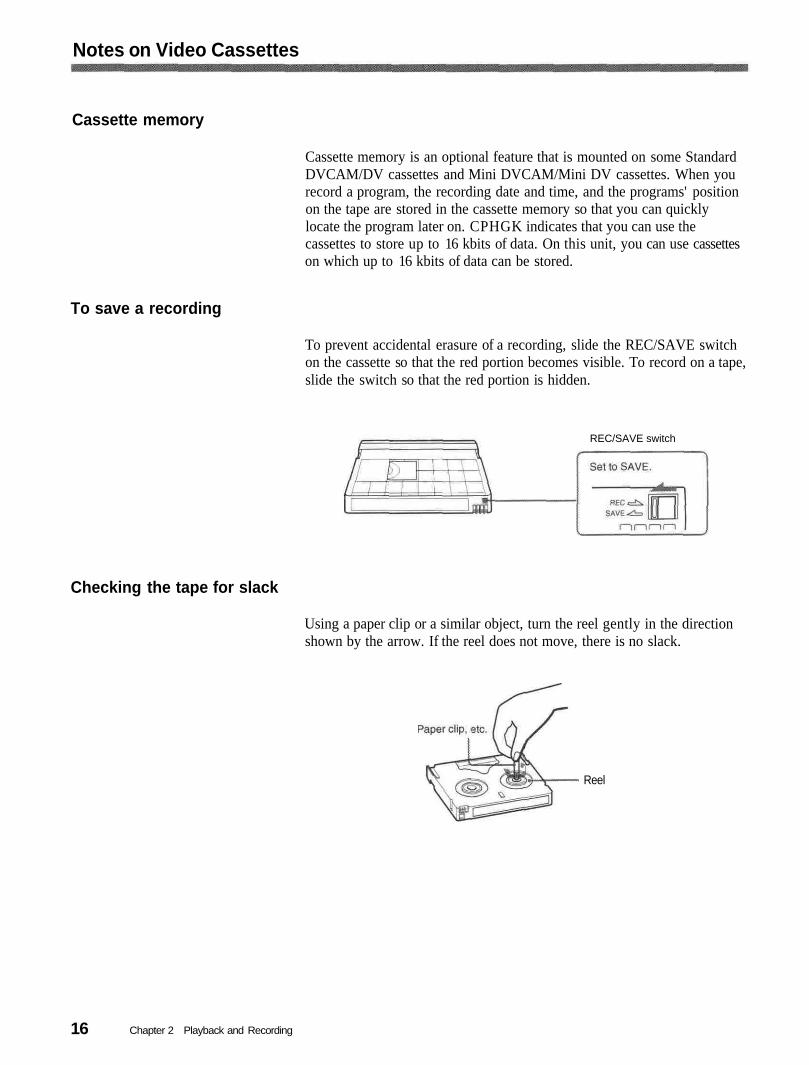
To prevent accidental erasure of a recording, slide the REC/SAVE switchon the cassette so that the red portion becomes visible. To record on a tape,slide the switch so that the red portion is hidden.
REC/SAVE switch
Checking the tape for slack
Using a paper clip or a similar object, turn the reel gently in the directionshown by the arrow. If the reel does not move, there is no slack.
Reel
Chapter 2 Playback and Recording16

Power PreparationsConnect the power cord (supplied) to the AC adaptor (AC-SU1, supplied)and connect the AC adaptor to the DC IN 12V connector on the unit. Then,connect the power plug to the wall outlet.When you undo these connections, be sure to disconnect the power cordfrom the wall outlet first.
DSR-11
AC adaptorAC-SU1 (supplied)
to DC IN 12Vconnector
Power cord (supplied)to wall outlet
Inserting/Ejecting Cassettes
To insert a cassette
• Do not insert the cassette forcibly. The unit may be damaged.• Do not eject/load the cassette in a place subject to light. Make sure to
close the cassette lid when using the unit. The internal sensor of the unitmay operate incorrectly if too much light finds its way into the unit.
1 With the unit powered on, confirm that theooen the cassette lid.
indicator is off, then
(Continued)
Chapter 2 Playback and Recording I 7

Preparations
After checking the tape for slack, hold the cassette so that the tapewindow is facing upward, then insert it into the unit.
2
Mini cassetteInsert the mini cassette into thecenter of the cassette compartment.
Standard cassette
Tape window facing upward
3The cassette is automatically loaded into the unit.
Close the cassette lid.
To eject the cassette
With the unit powered on, open the cassette lid. Press the EJECTbutton located at the right side of the cassette compartment.
1
The cassette is unloaded and ejected.
2 Remove the cassette from the unit. Close the cassette lid.
Chapter 2 Playback and Recording18

Notes on Recording/PlaybackNo compensation for contents of the recordingContents of the recording cannot be compensated for if recording orplayback is not successful due to a malfunction of the unit, video tape, etc.
Copyright precautionsOn recordingYou cannot record any software having copyright protection signals onthis unit. If you start recording protected video and audio signals, awarning appears on the monitor screen and the unit stops recording.
On playbackIf you play back a software having copyright protection signals on thisunit, you may not be able to copy it onto other equipment.
Limitations caused by the difference in formatThe unit can record and play back tapes recorded in DVCAM format. Itcan also record and play back tapes recorded in DV format (SP mode).However, due to the difference in format, you may not be able to record oredit some tapes affected by recording conditions of the tape.For details, see "Compatibility of DVCAM and DV Format" on page 55 .
Chapter 2 Playback and Recording 19
This section describes the necessary connections, settings, and operationsto perform playback on this unit. The same settings and operations applywhether you are using the unit for dubbing or as a stand-alonevideocassette player.
Connections for Playback
To equipment with a DV jack
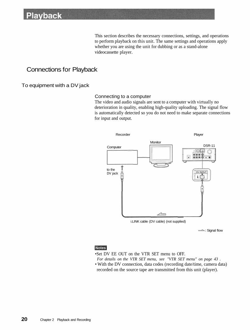
Connecting to a computerThe video and audio signals are sent to a computer with virtually nodeterioration in quality, enabling high-quality uploading. The signal flowis automatically detected so you do not need to make separate connectionsfor input and output.
Recorder Player
Monitor
to theDV jack
DSR-11Computer
i.LINK cable (DV cable) (not supplied)
Signal flow
•Set DV EE OUT on the VTR SET menu to OFF.For details on the VTR SET menu, see "VTR SET menu" on page 43 .
• With the DV connection, data codes (recording date/time, camera data)recorded on the source tape are transmitted from this unit (player).
Chapter 2 Playback and Recording20
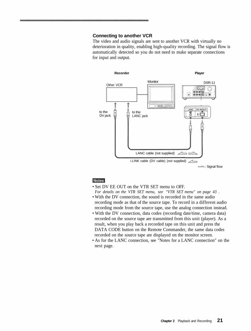
Connecting to another VCRThe video and audio signals are sent to another VCR with virtually nodeterioration in quality, enabling high-quality recording. The signal flow isautomatically detected so you do not need to make separate connectionsfor input and output.
Recorder Player
Monitor DSR-11Other VCR
to theLANC jack
LANC cable (not supplied)
i.LINK cable (DV cable) (not supplied)
to theDV jack
Signal flow
• Set DV EE OUT on the VTR SET menu to OFF.For details on the VTR SET menu, see "VTR SET menu" on page 43 .
• With the DV connection, the sound is recorded in the same audiorecording mode as that of the source tape. To record in a different audiorecording mode from the source tape, use the analog connection instead.
• With the DV connection, data codes (recording date/time, camera data)recorded on the source tape are transmitted from this unit (player). As aresult, when you play back a recorded tape on this unit and press theDATA CODE button on the Remote Commander, the same data codesrecorded on the source tape are displayed on the monitor screen.
• As for the LANC connection, see "Notes for a LANC connection" on thenext page.
Chapter 2 Playback and Recording 21
Playback
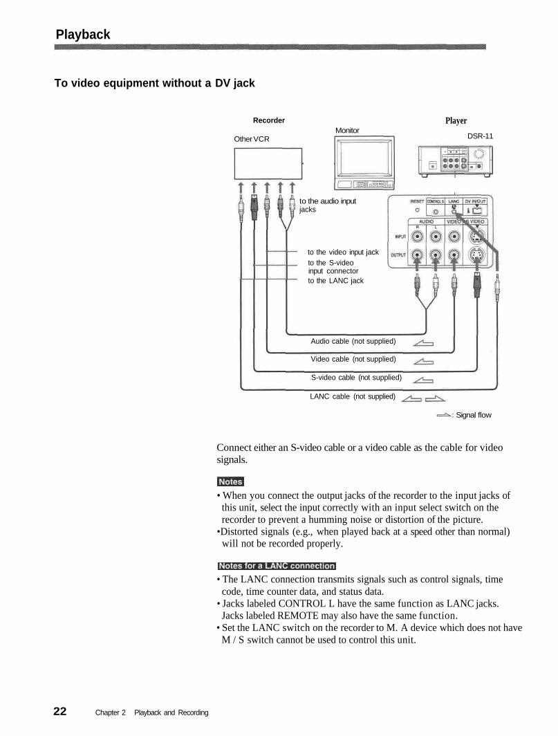
To video equipment without a DV jack
LANC cable (not supplied)
PlayerRecorder
Other VCRMonitor
DSR-11
to the audio inputjacks
to the video input jackto the S-videoinput connectorto the LANC jack
Audio cable (not supplied)
S-video cable (not supplied)
Video cable (not supplied)
Signal flow
Connect either an S-video cable or a video cable as the cable for videosignals.
• When you connect the output jacks of the recorder to the input jacks ofthis unit, select the input correctly with an input select switch on therecorder to prevent a humming noise or distortion of the picture.
•Distorted signals (e.g., when played back at a speed other than normal)will not be recorded properly.
• The LANC connection transmits signals such as control signals, timecode, time counter data, and status data.
• Jacks labeled CONTROL L have the same function as LANC jacks.Jacks labeled REMOTE may also have the same function.
• Set the LANC switch on the recorder to M. A device which does not haveM / S switch cannot be used to control this unit.
Chapter 2 Playback and Recording22
Preparation on the player (this unit)
Various text data are superimposed and output from the VIDEO jack orthe S VIDEO connector on the OUTPUT jacks. If you want to recordvideo signals without text data, carry out the following operations.• Set TITLE DISP and LABEL DISP on the CM SET menu to OFF.• Depending on the displayed items, press the MENU, DATA CODE,
DISPLAY or SEARCH SELECT button on the Remote Commander toclear the text data on the monitor screen.For details on text data, see "Displaying data recorded on a tape " on page 25
and "Displaying various data " on page 26 .For details on the CM SET menu, see "CM SET menu" on page 46 .
1
2
34
Power on the video monitor, then set the monitor's input switchaccording to the signals input from the recorder.
Set up the recorder.
For details, refer to the instruction manual of the recorder.
Power on this unit by pressing the ON/STANDBY switch on this unit.
When you play back a tape recorded in 4-channel mode (Fs32k),adjust the balance between channel 1/2 and channel 3/4 with AUDIOMIX on the AUDIO SET menu.
For details on the AUDIO SET menu, see "AUDIO SET menu" on page 44
The AUDIO MIX on the AUDIO SET menu (audio balanceadjustment) does not function on the source audio output through theDV IN/OUT connector.
Chapter 2 Playback and Recording 23

Playback
This section describes the procedures used to play back a tape and sendsignals to another VCR. For details on the procedures required when usinga computer as a recorder, refer to the instruction manual of your computeror the user's manuals of the software installed in it.
1 After checking the tape for slack and confirming that the indicatoris off, hold the cassette so that the tape window is facing upward, theninsert it into this unit.
For details on checking the tape for slack, see "Notes on Video Cassettes" onpage 15 .
Do not insert the cassette forcibly. The unit may be damaged.
The cassette is automatically loaded into the unit.
Press the PLAY button.2This unit starts playback.
To stop playbackPress the STOP button on the unit.
To pause playbackPress the PAUSE button on the unit.
• When this unit is playing back a part of the tape where the recordingformat has been changed between the DVCAM format and the DVformat, the picture and sound may be distorted.
• This unit cannot play back a tape recorded in the LP mode of theconsumer DV format.
Chapter 2 Playback and Recording24

Displaying data recorded on a tape
If you record on a tape using a Sony digital camcorder (DSR-200/200P,200A/200AP, PD100/PD100P, PD100A/PD100AP, PD150/PD150P, 250/250P, etc.), data codes (the shutter speed, SteadyShot, program AE mode,white balance, iris, gain, date and time) can be recorded on the tape. Youcan check these data items during playback on this unit.
Press the DATA CODE button on the Remote Commander duringplayback.Each time you press the DATA CODE button, the display changes asfollows.
No indicator
Recordingdate/time
Date
Time
Shutter speed
SteadyShot
Program AE
White balance
Gain
Iris
(Continued)
Chapter 2 Playback and Recording 25

Playback
• The data codes are also displayed by setting DATA CODE on theDISPLAY SET menu. You can change the displayed item in the sameway as described above.Example
Menu setting : CAMERADisplay : camera data—> no indicator —> recording date/time —> camera data
For details on the DISPLAY SET menu, see "DISPLAY SET menu " on page 45
• Camera data items show the settings of a tape recorded by a digitalcamcorder (DSR-200/200P, 200A/200AP, PD100/PD100P, PD100A/PD100AP, PD150/PD150P, 250/250P, etc.). This unit cannot recordcamera data.
• When the data codes were not recorded, "- - -" appears instead.• Some of the camera data items displayed on the monitor screen by thisunit are different from those shown by the digital camcorder.
Displaying various data
You can check various data items such as the time code, tape remainingtime, etc. on the monitor screen. These data items are useful for normalrecording/playback operation.
An item with * is displayed when you press the DISPLAY button on the RemoteCommander.You can hide the item by pressing the DISPLAY button again.
Cassette memory indicator*This is shown when a cassette with cassette memory has been loaded.
Tape transport mode indicator*Displays the tape transport mode.
Chapter 2 Playback and Recording26
Time code indicator*•Displays the time code. In the drop frame mode (only for NTSC), a
period is displayed between the minute and second. (Example:00:12.58:00)
•Displays the diagnostics code numbers if the self-diagnostic function isenabled.
Tape remaining time indicator*If REMAIN on the DISPLAY SET menu has been set to ON, theremaining tape time is displayed.
If the tape has been rewound to the beginning, this indicator will not showthe tape time remaining when the tape is inserted into the unit. Theremaining tape time is displayed after the tape runs for a while.
Search indicatorDisplays the search mode when you search for scenes with the RemoteCommander or the DSRM-20 (not supplied).For details on the search function, see "Searching using the search function" onpage 29 .
Index indicator*Displays the INDEX MARK when an index has been marked.
Caution indicators*Displays a caution.For details on cautions, see "Alarm Messages" on page 51 .
DVCAM/DV indicator*In the EE and recording modes, displays the recording format selected inREC MODE on the VTR SET menu. During playback, displays therecording format recorded on the tape.
Audio mode indicator*In the EE and recording modes, displays the audio mode selected inAUDIO MODE on the AUDIO SET menu. During playback, displays theaudio mode recorded on the tape. When inputting signals from the DV IN/OUT connector, displays the audio mode of signals input from the DV IN/OUT connector.
Input signal indicator*Displays the INPUT SELECT selector setting.
NS (Non Standard) audio mode indicator*This is shown when you play back a tape in the unlock audio mode orwhen the unlock mode signal has been input from the DV IN/OUTconnector. Always this is shown when the REC MODE on the VTR SETmenu has been set to DV SP and the unit is in the EE mode.For details on the unlock mode, see "Compatibility of DVCAM and DV Format"on page 55 .
Chapter 2 Playback and Recording 27
Playback
Playing at various speeds
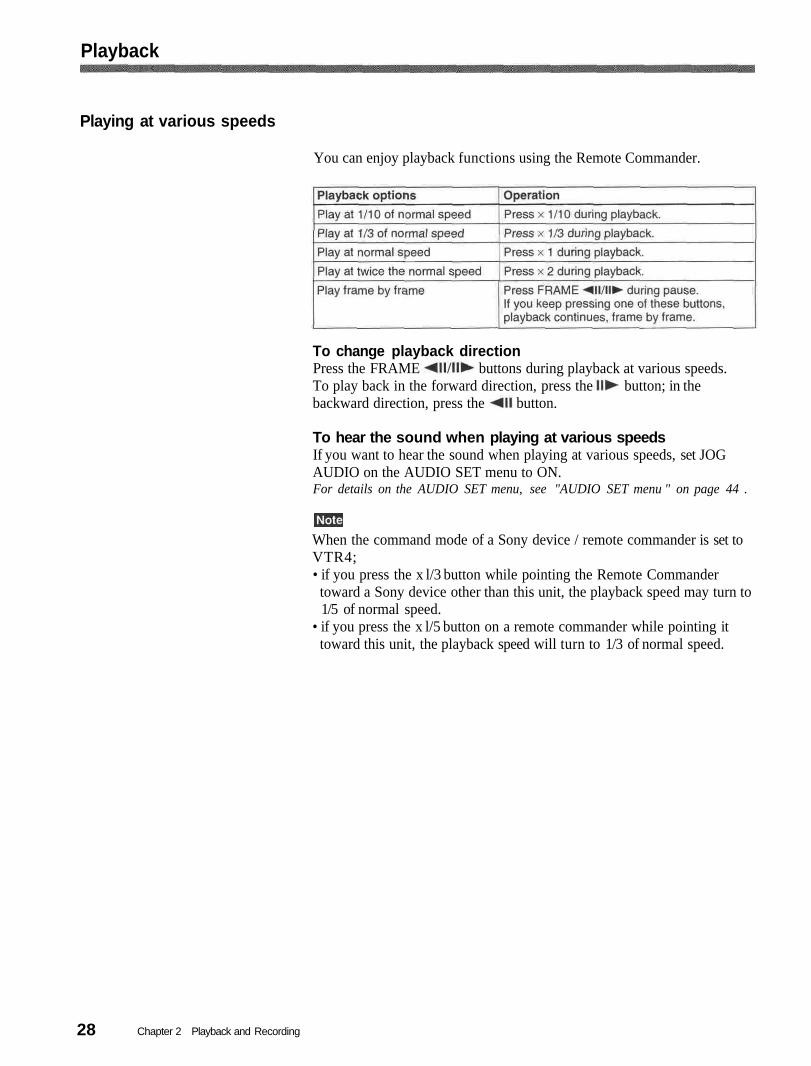
You can enjoy playback functions using the Remote Commander.
To change playback directionPress the FRAME buttons during playback at various speeds.To play back in the forward direction, press the button; in thebackward direction, press the button.
To hear the sound when playing at various speedsIf you want to hear the sound when playing at various speeds, set JOGAUDIO on the AUDIO SET menu to ON.For details on the AUDIO SET menu, see "AUDIO SET menu " on page 44 .
When the command mode of a Sony device / remote commander is set toVTR4;• if you press the x l/3 button while pointing the Remote Commandertoward a Sony device other than this unit, the playback speed may turn to1/5 of normal speed.
• if you press the x l/5 button on a remote commander while pointing ittoward this unit, the playback speed will turn to 1/3 of normal speed.
Chapter 2 Playback and Recording28
Searching using the search function
There are four kinds of search available on this unit:- Searching for the beginnings of recordings: Index search- Searching for the boundaries of recorded tape by title: Title search*- Searching for a point on the tape where the recorded date changes: Date
search- Searching for scenes recorded in the photo mode with a digital
camcorder: Photo search-*A function available only on a cassette with cassette memory
Searching with the cassette memoryIf you set the CM SEARCH on the CM SET menu to ON and the tape hascassette memory, the recordings are listed in the chronological order inwhich they were made. You can search using this chronological list.If the tape does not have cassette memory, you cannot search for scenes inchronological order.For details on the CM SET menu, see "CM SET menu" on page 46 .
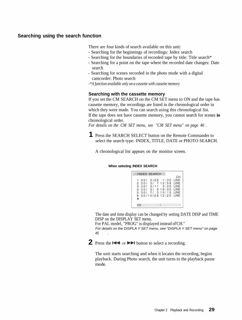
1 Press the SEARCH SELECT button on the Remote Commander toselect the search type: INDEX, TITLE, DATE or PHOTO SEARCH.
A chronological list appears on the monitor screen.
When selecting INDEX SEARCH
The date and time display can be changed by setting DATE DISP and TIMEDISP on the DISPLAY SET menu.For PAL model, "PROG" is displayed instead of'CH."For details on the DISPLA Y SET menu, see "DISPLA Y SET menu" on page45 .
2 Press the button to select a recording.
The unit starts searching and when it locates the recording, beginsplayback. During Photo search, the unit turns to the playback pausemode.
Chapter 2 Playback and Recording 29
Playback
Searching without cassette memoryWhen you use a tape without cassette memory, the unit searches in theorder of the actual positions of the recordings, regardless of the setting ofCM SEARCH on the CM SET menu.When you use a tape with cassette memory, set CM SEARCH on the CMSET menu to OFF.For details on the CM SET menu, see "CM SET menu" on page 46
The title search is not available in searching without cassette memory.
1 Press the SEARCH SELECT button on the Remote Commander toselect the search type.
When selecting INDEX SEARCH
2 Press the button repeatedly to locate the recording youwant.
Each time you press the or button, the unit searches for theprevious or next search point. When an search point is located, itsnumber is indicated on the monitor screen.The unit starts searching backwards or forwards until the numbercomes to zero, then plays back the recording. During Photo search, theunit turns to the playback pause mode.
How signals are recordedThere are four different signal types, one for each search method; index,title, date and photo signals. They are recorded by the digital camcorder(DSR-200/200P, 200A/200AP, PD100/PD100P, PD100A/PD100AP,PD150/PD150P, 250/250P, etc.). However, the type of signal recorded andwhere it is recorded (on the tape or in the cassette memory) depends onwhether the cassette has cassette memory or which type of videoequipment is used for recording. Please note that if the signals for a certainsearch type are not recorded, you cannot do that type of search. For detailson the signals used for a particular type of search, refer to the instructionmanual of the recorder.
30 Chapter 2 Playback and Recording
When you record on this unit
Signals forIndex search*Title searchDate searchPhoto search
In cassette memoryYesNoNoNo
On tapeYesNoYesNo
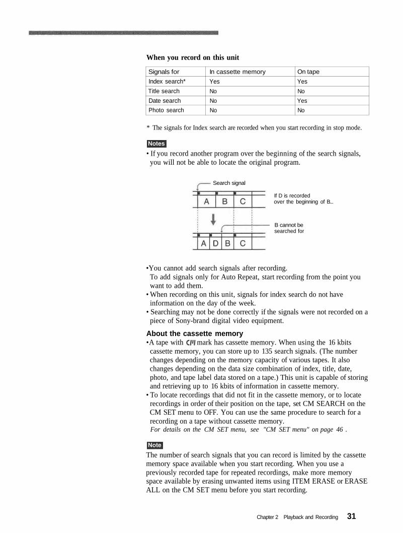
* The signals for Index search are recorded when you start recording in stop mode.
• If you record another program over the beginning of the search signals,you will not be able to locate the original program.
Search signal
If D is recordedover the beginning of B...
B cannot besearched for
•You cannot add search signals after recording.To add signals only for Auto Repeat, start recording from the point youwant to add them.
• When recording on this unit, signals for index search do not haveinformation on the day of the week.
• Searching may not be done correctly if the signals were not recorded on apiece of Sony-brand digital video equipment.
About the cassette memory•A tape with mark has cassette memory. When using the 16 kbits
cassette memory, you can store up to 135 search signals. (The numberchanges depending on the memory capacity of various tapes. It alsochanges depending on the data size combination of index, title, date,photo, and tape label data stored on a tape.) This unit is capable of storingand retrieving up to 16 kbits of information in cassette memory.
• To locate recordings that did not fit in the cassette memory, or to locaterecordings in order of their position on the tape, set CM SEARCH on theCM SET menu to OFF. You can use the same procedure to search for arecording on a tape without cassette memory.For details on the CM SET menu, see "CM SET menu" on page 46 .
The number of search signals that you can record is limited by the cassettememory space available when you start recording. When you use apreviously recorded tape for repeated recordings, make more memoryspace available by erasing unwanted items using ITEM ERASE or ERASEALL on the CM SET menu before you start recording.
Chapter 2 Playback and Recording 31

Playback
Auto Repeat
This unit can repeat the playback of all or a part of the tape.
1 Set the AUTO REPEAT switch on the rear panel to ON.
Press the REW button. (If the tape is already rewound, press the PLAYbutton.)
The unit rewinds the tape to its beginning, and starts playbackautomatically. The unit repeats the playback from the beginning to thefirst index (if there is no signal for index search on the tape, to the nextunrecorded portion; if there is no unrecorded portion, to the end of thetape).
Auto Repeat using an external AC timerIf you connect an external AC timer (not supplied) to this unit, you canrepeat playback automatically at the preset time.
2
1 Connect an external AC timer (not supplied) to this unit.
DSR-11
AC timer
AC adaptor
to a wall outlet
23
Set the AUTO REPEAT switch on the rear panel to ON.
Set the starting time on the external AC timer.
At the preset time, the power of this unit turns on, and after a fewseconds (no more than 30), Auto Repeat playback starts automatically.The unit repeats the playback from the beginning to the first index (ifthere is no signal for index search on the tape, to the next unrecordedportion; if there is no unrecorded portion, to the end of the tape).
Chapter 2 Playback and Recording32
• The unit cannot search for a signal for index search or an unrecordedportion within 20 seconds of the beginning of the playback.
• While a tape is running, be sure not to turn off the power by using an ACtimer. The unit and the tape may be damaged. When turning off thepower of the unit, make sure to press the STOP button on this unit first tostop the tape transport, then turn off the power.
To stop Auto RepeatPress the STOP button on this unit.
To release the Auto Repeat modeSet the AUTO REPEAT switch on the rear panel to OFF.
Chapter 2 Playback and Recording 33

This section describes the necessary connections, settings and operationsto perform recording on this unit. The same settings and operations applywhether you are using the unit for dubbing or as a stand-alone recorder.
Connections for Recording
To equipment with a DV jack
Connecting to a computerThe video and audio signals are sent from a computer with virtually nodeterioration in quality, enabling high-quality downloading. The signalflow is automatically detected so you do not need to make separateconnections for input and output.
Player RecorderMonitor
Computer
to theDV jack
DSR-11
i.LINK cable (DV cable) (not supplied)
Signal flow
• With the DV connection, data codes (recording date/time, camera data)are transmitted from the computer (player). However, the contents of thecassette memory are not transmitted.
• If no picture appears via the DV jack, disconnect, then reconnect thei.LINK cable (DV cable).
Chapter 2 Playback and Recording34

Connecting to another VCRThe video and audio signals are sent from another VCR with virtually nodeterioration in quality, enabling high-quality recording. The signal flow isautomatically detected so you do not need to make separate connections forinput and output.
Player Recorder
to theDV jack
DSR-11MonitorOther VCR
to theLANC jack
LANC cable (not supplied)
i.LINK cable (DV cable) (not supplied)
Signal flow
• With the DV connection, the sound is recorded in the same audiorecording mode as that of the source tape. To record in a different audiorecording mode from the source tape, use the analog connection instead.
•With the DV connection, data codes (recording date/time, camera data)recorded on the source tape are transmitted from the other VCR (player).As a result, when you play back a recorded tape on this unit and press theDATA CODE button on the Remote Commander, the same data codesrecorded on the source tape are displayed on the monitor screen.However, the contents of the cassette memory are not transmitted.
• If no picture appears via the DV jack, disconnect, then reconnect thei.LINK cable (DV cable).
• As for the LANC connection, see "Notes for the LANC connection" onthe next page.
35Chapter 2 Playback and Recording

Recording
To video equipment without a DV jack
RecorderMonitorPlayer
Other VCR DSR-11
to the audiooutput jacks
to the video outputjackto the S-videooutput connectorto the LANC jack
Audio cable (not supplied)
Video cable (not supplied)
S-video cable (not supplied)
LANC cable (not supplied)Signal flow
Connect either an S-video cable or a video cable as the cable for videosignals.
• When recording analog input signals, this unit can digitally output thesignals from the DV IN/OUT connector for backup. Set DV EE OUT onthe VTR SET menu to ON.For details on the VTR SET menu, see "VTR SET menu" on page 43).
• When you connect the output jacks of this unit to the input jacks of theplayer, select the input correctly with the INPUT SELECT selector on thisunit to prevent a humming noise or distortion of the picture.
• Distorted signals (e.g., when played back at a speed other than normal)will not be recorded properly.
• The LANC connection transmits signals such as control signals, timecode, time counter data, and status data.
' Jacks labeled CONTROL L have the same function as LANC jacks. Jackslabeled REMOTE may also have the same function.
Chapter 2 Playback and Recording36
Preparation on the recorder (this unit)
• Before recording, set the date and time on the unit so that the recordingtime can be written into the search signal. You can set the date and timeby setting CLOCK SET on the OTHERS menu.For details on the OTHERS menu, see "OTHERS menu" on page 49.
•Editing is not possible with a tape that is copyright protected.
1 Power on the video monitor, then set the monitor's input switchaccording to the signals input from this unit.
2 Set up the player to play back a tape.
For details, refer to the instruction manual of the player.
When the player is connected to the INPUT jacks on this unit, set theNTSC/PAL select switch on this unit to the appropriate positionaccording to the input signals.
For NTSC formatted signals, set the switch to NTSC and for PALformatted signals, set it to PAL.For details on the NTSC/PAL select switch setting, see "Rear Panel" on page12 .
• Do not change the NTSC/PAL select switch setting during recording.• If the color system of the input signals is different from that of the
switch setting, both picture and sound will be muted.• You do not need to set the NTSC/PAL select switch when inputtingthe signals to the DV IN/OUT connector. The unit detects the colorsystem of the input signal automatically. However when the NTSC/PAL select switch is set to PAL, the time code generated by the unitwhile recording in DVCAM format turns to the non-drop frame mode.Even if an NTSC formatted signal is input from the DV IN/OUTconnector, the time code generated by the unit is non-drop framemode regardless of the TC FORMAT setting on the OTHERS menu.If you intend to set the unit to generate the time code in the dropframe mode, set the switch to NTSC.
Power on this unit by pressing the ON/STANDBY switch on this unit.
(Continued)
4
Chapter 2 Playback and Recording 37
Recording
Select an input signal by switching the INPUT SELECT selector onthis unit.
DV: to record input signals from the DV IN/OUT connectorS VIDEO: to record input signals from the S VIDEO connector on the
INPUT jacksVIDEO: to record input signals from the VIDEO jack on the INPUT
jacks
5
Do not change the selector setting during recording. Otherwise, noiseis output to the picture and sound and that portion will not be recordedproperly.
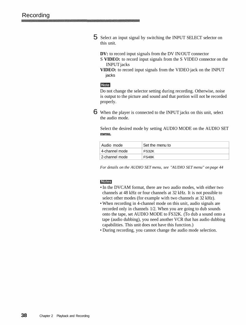
When the player is connected to the INPUT jacks on this unit, selectthe audio mode.
Select the desired mode by setting AUDIO MODE on the AUDIO SETmenu.
Audio mode4-channel mode2-channel mode
Set the menu toFS32K
FS48K
For details on the AUDIO SET menu, see "AUDIO SET menu" on page 44
• In the DVCAM format, there are two audio modes, with either twochannels at 48 kHz or four channels at 32 kHz. It is not possible toselect other modes (for example with two channels at 32 kHz).
• When recording in 4-channel mode on this unit, audio signals arerecorded only in channels 1/2. When you are going to dub soundsonto the tape, set AUDIO MODE to FS32K. (To dub a sound onto atape (audio dubbing), you need another VCR that has audio dubbingcapabilities. This unit does not have this function.)
• During recording, you cannot change the audio mode selection.
6
Chapter 2 Playback and Recording38
Recording ProcedureThis section describes the procedures used to record signals sent fromanother VCR to this unit. For details on the procedures required whenusing a computer as a player, refer to the instruction manual of yourcomputer or the user's manuals of the software installed in it.
After checking that the REC/SAVE switch is set to REC, checking thetape for slack and confirming that the [20] indicator is off, hold thecassette so that the tape window is facing upward, then insert it intothis unit.
For details on the REC/SAVE switch and checking the tape for slack, see"Notes on Video Cassettes" on page 75 .
The cassette is automatically loaded into the unit and the tape will stop.
2 Press the playback button on the player.
The player starts playback.
3 Press the PLAY button while holding down the REC button.
The unit starts recording and the index is marked.
To stop recordingPress the STOP button on the unit.
To pause recordingPress the PAUSE button on the unit.
To display useful data for recording on the monitor screenPress the DISPLAY button on the Remote Commander.For details on displayed data, see "Displaying various data " on page 26 ..
1
Chapter 2 Playback and Recording 39
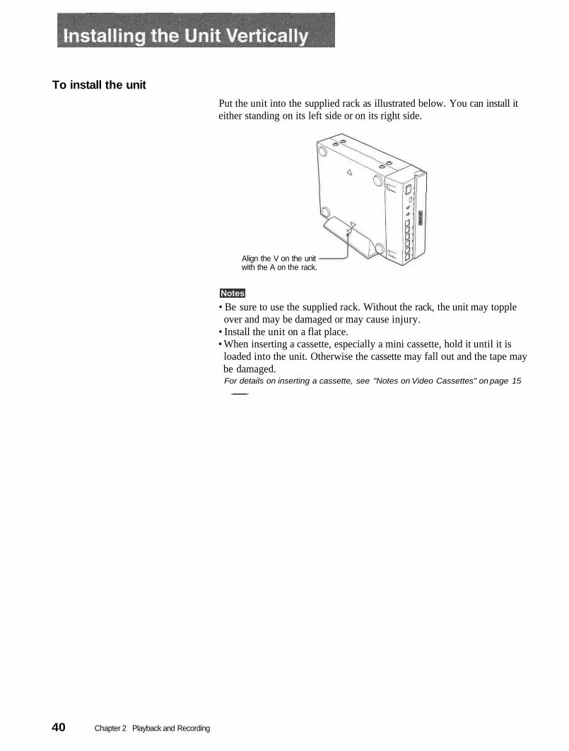
To install the unitPut the unit into the supplied rack as illustrated below. You can install iteither standing on its left side or on its right side.
Align the V on the unitwith the A on the rack.
• Be sure to use the supplied rack. Without the rack, the unit may toppleover and may be damaged or may cause injury.
• Install the unit on a flat place.• When inserting a cassette, especially a mini cassette, hold it until it is
loaded into the unit. Otherwise the cassette may fall out and the tape maybe damaged.For details on inserting a cassette, see "Notes on Video Cassettes" on page 15.
Chapter 2 Playback and Recording40

Chapter
Adjusting and SettingThrough Menus
Changing the menu settings
1The unit allows you to set various parameters in themenus. Before you start using the unit, set the internalclock in CLOCK SET on the OTHERS menu. Exceptfor clock setting, you can use all other factory-setdefault parameters but change them as needed.
Pressing the buttons on the RemoteCommander, select the menu icon you want tochange, then press the SET button on the RemoteCommander.
If the internal backup battery is exhausted, the menusettings will be initialized. The internal backup batteryis fully charged if you connect the power to the unitfor about 10 hours. The menu settings will be kept forabout one month.
Displaying the menu
2
345
Pressing thewant to change, then press the SET button.
Pressing the buttons, change the setting.
Press the SET button to return to the submenu.
Repeat steps 2 to 4, as needed.
buttons, select the submenu you
Press the MENU button on the Remote Commander.
The menu is superimposed on the analog video output. RETURN, thenbuttons, selectPressing theTo return to step 1
press the SET button.
To exit from the menuPress the MENU button again.
SubmenusIcons
Chapter 3 Adjusting and Setting Through Menus 41
Operating the Menus
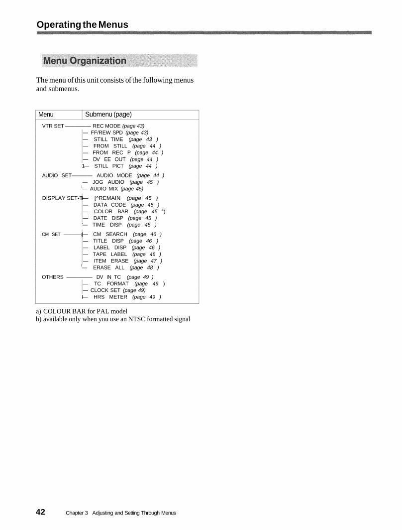
The menu of this unit consists of the following menusand submenus.
MenuVTR SET ————— REC MODE (page 43)
1— STILL PICT (page 44 )
AUDIO SET———— AUDIO MODE (page 44 )— JOG AUDIO (page 45 )
\— AUDIO MIX (page 45)
DISPLAY SET-T
'— TIME DISP (page 45 )
CM SET ————r
\— ERASE ALL (page 48 )
OTHERS ————— DV IN TC (page 49 )
I— HRS METER (page 49 )
Submenu (page)
— FF/REW SPD (page 43)— STILL TIME (page 43 )— FROM STILL (page 44 )— FROM REC P (page 44 )— DV EE OUT (page 44 )
i— [^REMAIN (page 45 )— DATA CODE (page 45 )— COLOR BAR (page 45 a)— DATE DISP (page 45 )
j— CM SEARCH (page 46 )— TITLE DISP (page 46 )— LABEL DISP (page 46 )— TAPE LABEL (page 46 )— ITEM ERASE (page 47 )
— TC FORMAT (page 49 )— CLOCK SET (page 49)
a) COLOUR BAR for PAL modelb) available only when you use an NTSC formatted signal
42 Chapter 3 Adjusting and Setting Through Menus

Menu ContentsInitial settings are indicated with rectangles.
VTR SET menu
Icon/Menu Submenu(page) Setting
VTR SET REC MODE Switches the recording mode between DVCAM and DV (SP mode only). When you playback a tape, the DVCAM/DV setting will be automatically switched; you do not need to usethis item.
Records in DVCAM format.DV SP: Records in DV format (SP mode).
• This unit is not compatible with playing or recording in LP mode of the consumer DV format.• You cannot change the setting while recording.• It is recommended that you record in the DVCAM format. There are some limitations with
respect to DV recording depending on machine specifications and the consumer DVformat as follows:- The head system is optimized for DVCAM recording. A DV recording overwrites the last
track just before the beginning of the recording. As a result, at the border of these tworecorded portions, picture and sound may be distorted.
- The sound will be recorded unsynchronized. (unlock mode)- The time code is fixed to the drop frame mode. (only for NTSC)- The DV IN TC setting on the OTHERS menu turns invalid. The unit records internal time
code.• If you dub a consumer DV tape from the DV IN/OUT connector on this unit, keep the
following in mind:- Set the REC MODE to DV SP. If the REC MODE has been set to DVCAM, a tape with
an invalid format (recording speed: DVCAM, sound: unsynchronized, unlock mode) willbe made. (The unit cannot convert unlock mode sound to lock mode sound.)
- If you edit a tape with an invalid format in the DSR-70/70P, DSR-80/80P, DSR-85/85P,DSR-2000/2000P, etc., there may be some restrictions.
For details on DVCAM/DV format compatibility, see "Compatibility of DVCAM and DVFormat" on page 55.
FF/REW SPD Selects the taoe transport mode in fast-forward and rewind.Fast-forwards or rewinds the tape at maximum speed without displaying the
picture.SHUTTLEMAX: Fast-forwards or rewinds the tape at maximum speed (about 14 times
normal speed for NTSC; about 17 times normal speed for PAL) while displaying thepicture.
STILL TIME Selects the time to switch to the tape protection mode from the still mode.30 SEC: 30 seconds
: 1 minute2 MIN: 2 minutes3 MIN: 3 minutes5 MIN: 5 minutes
• If the unit is left in playback pause mode for a long time, the tape or the video heads maybe damaged or the video heads may become clogged. Select the shortest time possible—particularly when using a Mini-DV cassette that is longer than 60 minutes, select 30SEC or1 MIN.
• When the setting is changed, the first tape protection mode change uses the time settingfrom before the settings were changed. From the second tape protection mode change,the new time setting is used.
(Continued)
43Chapter 3 Adjusting and Setting Through Menus
Operating the Menus
Icon/Menu Submenu(page) Setting
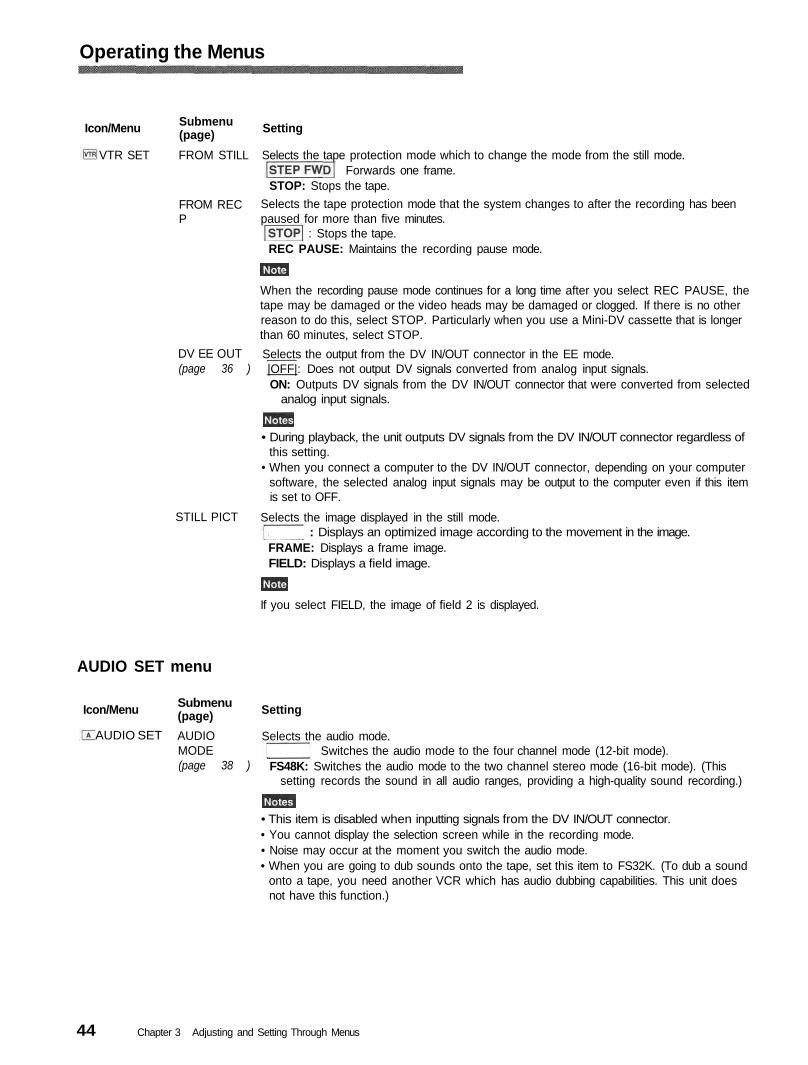
VTR SET FROM STILL Selects the tape protection mode which to change the mode from the still mode.Forwards one frame.
STOP: Stops the tape.FROM RECP
Selects the tape protection mode that the system changes to after the recording has beenpaused for more than five minutes.
: Stops the tape.REC PAUSE: Maintains the recording pause mode.
When the recording pause mode continues for a long time after you select REC PAUSE, thetape may be damaged or the video heads may be damaged or clogged. If there is no otherreason to do this, select STOP. Particularly when you use a Mini-DV cassette that is longerthan 60 minutes, select STOP.
DV EE OUT(page 36 )
Selects the output from the DV IN/OUT connector in the EE mode.|OFF|: Does not output DV signals converted from analog input signals.ON: Outputs DV signals from the DV IN/OUT connector that were converted from selected
analog input signals.
• During playback, the unit outputs DV signals from the DV IN/OUT connector regardless ofthis setting.
• When you connect a computer to the DV IN/OUT connector, depending on your computersoftware, the selected analog input signals may be output to the computer even if this itemis set to OFF.
STILL PICT Selects the image displayed in the still mode.: Displays an optimized image according to the movement in the image.
FRAME: Displays a frame image.FIELD: Displays a field image.
If you select FIELD, the image of field 2 is displayed.
AUDIO SET menu
Icon/Menu Submenu(page) Setting
AUDIO SET AUDIOMODE(page 38 )
Selects the audio mode.Switches the audio mode to the four channel mode (12-bit mode).
FS48K: Switches the audio mode to the two channel stereo mode (16-bit mode). (Thissetting records the sound in all audio ranges, providing a high-quality sound recording.)
• This item is disabled when inputting signals from the DV IN/OUT connector.• You cannot display the selection screen while in the recording mode.• Noise may occur at the moment you switch the audio mode.• When you are going to dub sounds onto the tape, set this item to FS32K. (To dub a sound
onto a tape, you need another VCR which has audio dubbing capabilities. This unit doesnot have this function.)
44 Chapter 3 Adjusting and Setting Through Menus
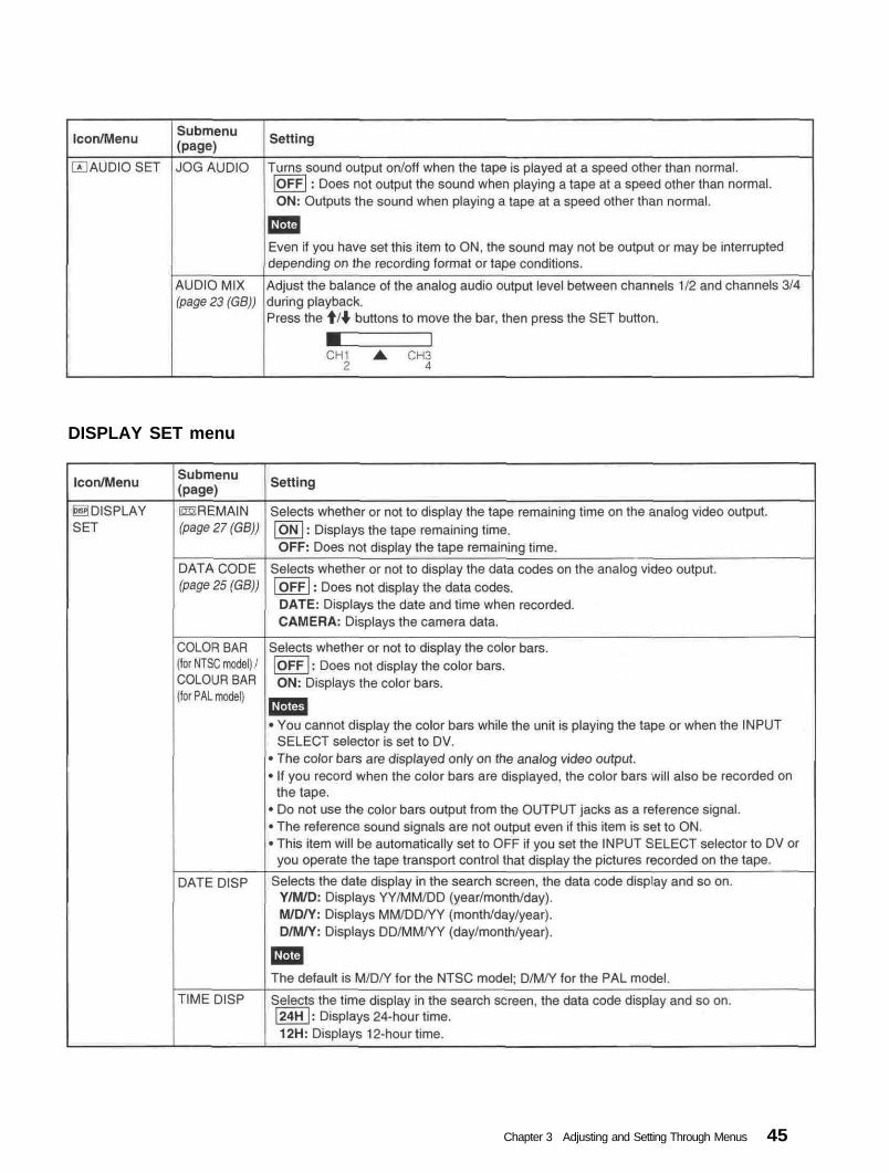
DISPLAY SET menu
45Chapter 3 Adjusting and Setting Through Menus
Operating the Menus
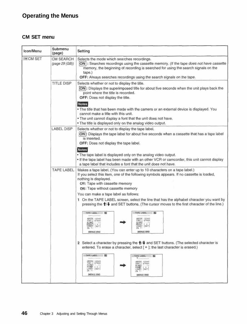
CM SET menu
46 Chapter 3 Adjusting and Setting Through Menus

(Continued)
47Chapter 3 Adjusting and Setting Through Menus

Operating the Menus
48 Chapter 3 Adjusting and Setting Through Menus
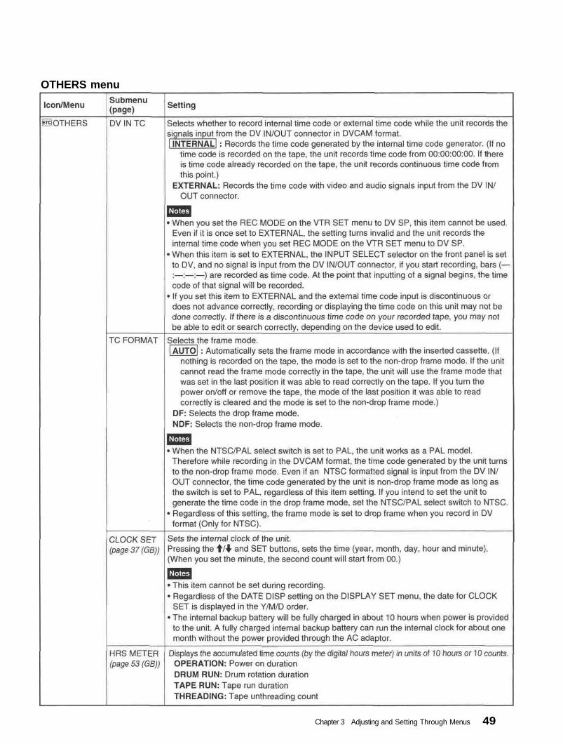
OTHERS menu
49Chapter 3 Adjusting and Setting Through Menus

Chapter4Maintenance
Please check the following before contacting your Sony dealer.
SymptomThe power cannot be turned on.The unit will not operate even if the powerhas been turned on.
The cassette cannot be inserted.
It takes time to eject the cassette.No picture.Noise appears on the screen.
No picture via the DV jack.
The audio is noisy.Pause is released automatically.The picture and sound are muted in theEE or recording mode.The Remote Commander or remotecontrol unit does not work.Though DV IN TC on the OTHERS menuwas set to EXTERNAL, the time code ofthe signals input from the DV IN/OUTconnector cannot be recorded.When the unit is recording an NTSCformatted signal input from the DV IN/OUTconnector in DVCAM format, even if theTC FORMAT on the OTHERS menu is setto DF, the time code is recorded in non-drop frame mode.
Cause/RemedyThe AC adaptor is disconnected. ---- Connect the AC adaptor.• Moisture condensation has occurred. --- Turn off the power and disconnect the
AC adaptor. Connect the AC adaptor after about one minute and turn on thepower. Then, if there is a cassette in the unit, remove the cassette and keep thecassette lid open, power on the unit and leave it on for more than one hour.
• The cassette is not inserted straight. --- Insert it straight.• There is moisture condensation on the head drum. --- Keep the cassette lid
open and turn the power on. Then, wait more than one hour.• The cassette is not inserted straight. --- Insert it straight.• Another cassette has been loaded already.--- Remove the cassette and insert
the one you want to load.This is not a malfunction.--- This unit ejects the cassette slowly to protect the tape.The video heads are dirty. — Clean the video heads using the supplied cleaning cassette.• A damaged cassette is inserted. — Insert another cassette.• The video heads are dirty. — Clean the video heads using the supplied
cleaning cassette.• Reconnect the i.LINK cable (DV cable) (not supplied).• The INPUT SELECT selector is set to other than DV. -— Set it to DV.A damaged cassette is inserted. — Insert another cassette.Pause mode is automatically released to protect the tape.
The NTSC/PAL select switch setting is not appropriate. — Set it to a suitableposition for the color system of the input signals.The REMOTE CONTROL switch setting is not appropriate. — Set it to a suitableposition for the device you use.The REC MODE on the VTR SET menu is set to DV SP. Set the REC MODEto DVCAM.
The NTSC/PAL select switch is set to PAL. —- Set it to NTSC.
Chapter 4 Maintenance50

If an error occurs, a caution appears on the analog video outputs when you set the unit to output signals with dataitems. Check them with the following list.For details on data items, see "Displaying various data " on page 26
Description/RecoveryIndicator lamp (flash)a)
CAUTIONMonitor
Rapid flashing
Rapid flashing
Slow flashing
Slow flashing
Slow flashing
Slow flashing
Slow flashing
Rapid flashing
Rapid flashing
Moisture condensation (without a cassette) —»• Keep the cassette lidopen and turn the power on, then wait more than one hour.
Moisture condensation (with a cassette) —»• Remove the cassette andkeep the cassette lid open and turn the power on, then wait more thanone hour.You tried to record without a cassette inserted. —»• Insert a cassette.
The tape is reaching the end during recording. —»• Provide a newcassette.The tape reached the end and still tried to record. —»• Rewind the tape orreplace the tape with a new one.The cassette is write-protected (The REC/SAVE switch is set to SAVE) andyou tried to record. —»• Set the REC/SAVE switch to REC or use anothercassette (See page 16 .You did not set the clock when you turned on the unit. —>• Set the clockwith the menu (See page 49)You tried to record a copyright-protected source.—»• You cannot record a copyright-protected source (See page 19.The video heads are clogged. —»• Clean the video heads with the suppliedcleaning cassette. (The unit detects if the video heads are clean onlybefore recording. If the video heads get clogged during recording, the unitcannot detect it.)
The unit is running the self-diagnostics (See page 54 . This cautiondisplay ceases when you turn on/off the power of the unit.
NO TAPE
TAPE END
CLOCK SET
COPYINHIBIT
0t Displayed
alternately
CLEANINGCASSETTE
a: The indicator flashes 3.2 times per second in the rapid flashing mode and flashes 0.8 time per second in the slow flashingmode.
51Chapter 4 Maintenance

If you do, its cabinet, mechanical parts, etc., may bedamaged.
Notes on the video cassette recorder
Do not install the unit in a place subject todirect sunlight or heat sources
Do not install the unit in an extremely hotplaceIf the unit is left in a car parked with its windowsclosed (especially in summer), its cabinet may bedamaged or it may not work correctly.
To prevent electromagnetic interferencecaused by radio communication equipmentsuch as cellular phones, transceivers, etc.The use of the radio communication equipment such ascellular phones or transceivers near the unit may causea malfunction and can affect the audio/video signals.The cellular phones or transceivers near the unit shouldbe switched off.
Do not use the unit in an area exposed toradiationA malfunction may occur.
If the unit is brought directly from a cold to awarm locationMoisture may condense inside the unit and causedamage to the video head and tape. If you use the unitin a place subject to direct cold currents from an airconditioner, moisture may also condense inside theunit.
Do not place a heavy object on the unitThe cabinet may be damaged, or the unit may not workcorrectly.
Do not handle the unit roughlyAvoid rough handling or mechanical shock.
To avoid damaging the cabinet finishPlastic is often used for the surface finishing of theunit. Do not spray a volatile solvent such as aninsecticide toward the cabinet or place rubber or vinylproducts on the cabinet for a long time. If you do, thefinish of the cabinet may be damaged or the coatingmay come off.
Do not clean the cabinet with thinner orbenzineThe cabinet may be damaged or its coating may comeoff. When you use a chemical-impregnated cloth, useit according to its directions.
Clean the cabinet with soft dry clothWhen the cabinet is very dirty, clean it with a soft drycloth lightly moistened with a mild detergent solutionand finish it with a dry cloth.
Do not put magnetic objects close to the unitMagnetic fields may damage the recording.
Checking the video heads every 1000 hoursA VCR is a high-precision piece of equipment thatrecords and plays back the picture on a magnetic tape.In particular, the video heads and other mechanicalparts become dirty or worn. To maintain a cleanpicture, we recommend maintenance every 1000 hours,though the conditions of use may differ depending ontemperature, humidity, dust, etc.
Cleaning of the video heads
If the video heads are contaminated, the picturescannot be recorded properly or the playback picturesbecome noisy. If the following phenomena occur, usethe cleaning cassette (supplied) to clean the heads.•Square-shaped noise appears on the playback picture.• A part of the playback picture does not move.• The playback picture does not appear on the screen.
Symptoms caused by contaminated video heads
If these images appear on thescreen, use the cleaning cassette.
Normal picture
To use the cleaning cassetteRefer to your cleaning cassette's operating instructions
After prolonged use, the video heads may becomeworn out. If optimum picture quality is not restoredeven after you have cleaned the video heads with thecleaning cassette, the video heads may have worn out.In that case, you have to replace the video heads withnew ones. Please consult your Sony dealer.
52 Chapter 4 Maintenance
Notes on the video cassettes
If the cassette memory function does not workReinsert the cassette a few times. The terminal portionof the cassette may be dusty or dirty.
When bringing the unit or tape from a cold place to awarm place or vice versa, put it in a plastic bag andseal the bag tightly. After bringing it into the newplace, leave the bag on for more than one hour, andremove the bag when the air temperature inside it hasreached the temperature surrounding it.
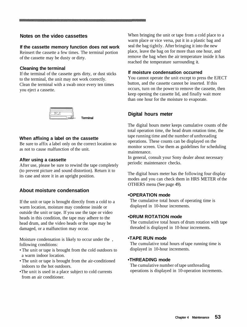
Cleaning the terminalIf the terminal of the cassette gets dirty, or dust sticksto the terminal, the unit may not work correctly.Clean the terminal with a swab once every ten timesyou eject a cassette.
If moisture condensation occurredYou cannot operate the unit except to press the EJECTbutton, and the cassette cannot be inserted. If thisoccurs, turn on the power to remove the cassette, thenkeep opening the cassette lid, and finally wait morethan one hour for the moisture to evaporate.
TerminalDigital hours meter
When affixing a label on the cassetteBe sure to affix a label only on the correct location soas not to cause malfunction of the unit.
After using a cassetteAfter use, please be sure to rewind the tape completely(to prevent picture and sound distortion). Return it toits case and store it in an upright position.
About moisture condensation
If the unit or tape is brought directly from a cold to awarm location, moisture may condense inside oroutside the unit or tape. If you use the tape or videoheads in this condition, the tape may adhere to thehead drum, and the video heads or the tape may bedamaged, or a malfunction may occur.
Moisture condensation is likely to occur under the ,following conditions:• The unit or tape is brought from the cold outdoors toa warm indoor location.
• The unit or tape is brought from the air-conditionedindoors to the hot outdoors.
•The unit is used in a place subject to cold currentsfrom an air conditioner.
The digital hours meter keeps cumulative counts of thetotal operation time, the head drum rotation time, thetape running time and the number of unthreadingoperations. These counts can be displayed on themonitor screen. Use them as guidelines for schedulingmaintenance.In general, consult your Sony dealer about necessaryperiodic maintenance checks.
The digital hours meter has the following four displaymodes and you can check them in HRS METER of theOTHERS menu (See page 49).
•OPERATION modeThe cumulative total hours of operating time isdisplayed in 10-hour increments.
•DRUM ROTATION modeThe cumulative total hours of drum rotation with tapethreaded is displayed in 10-hour increments.
•TAPE RUN modeThe cumulative total hours of tape running time isdisplayed in 10-hour increments.
•THREADING modeThe cumulative number of tape unthreadingoperations is displayed in 10-operation increments.
53Chapter 4 Maintenance
Notes on Use
Self-diagnostics function
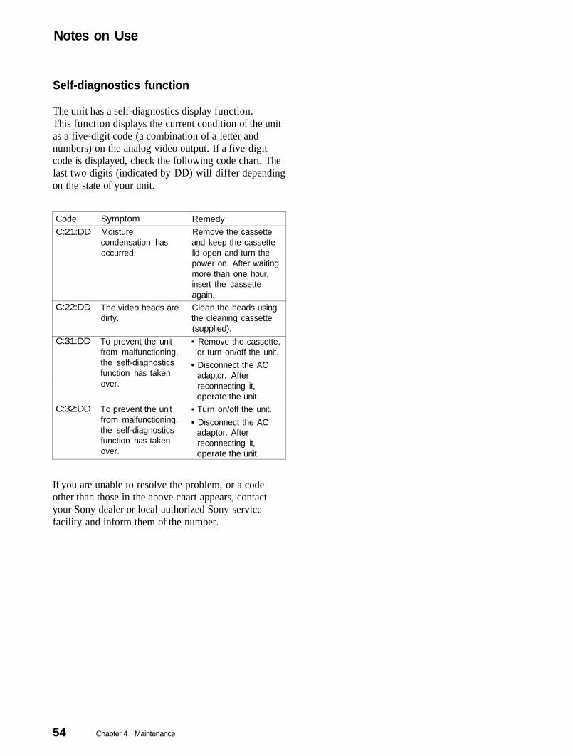
The unit has a self-diagnostics display function.This function displays the current condition of the unitas a five-digit code (a combination of a letter andnumbers) on the analog video output. If a five-digitcode is displayed, check the following code chart. Thelast two digits (indicated by DD) will differ dependingon the state of your unit.
CodeC:21:DD
C:22:DD
C:31:DD
C:32:DD
SymptomMoisturecondensation hasoccurred.
The video heads aredirty.
To prevent the unitfrom malfunctioning,the self-diagnosticsfunction has takenover.
To prevent the unitfrom malfunctioning,the self-diagnosticsfunction has takenover.
RemedyRemove the cassetteand keep the cassettelid open and turn thepower on. After waitingmore than one hour,insert the cassetteagain.Clean the heads usingthe cleaning cassette(supplied).• Remove the cassette,
or turn on/off the unit.• Disconnect the AC
adaptor. Afterreconnecting it,operate the unit.
• Turn on/off the unit.• Disconnect the AC
adaptor. Afterreconnecting it,operate the unit.
If you are unable to resolve the problem, or a codeother than those in the above chart appears, contactyour Sony dealer or local authorized Sony servicefacility and inform them of the number.
54 Chapter 4 Maintenance

Appendix
The DVCAM format was developed as a more reliable and higher endformat than the consumer DV format. Here we explain the DVCAM andDV formats: the differences, compatibility and limitations on editing.
Differences between DVCAM and DV format
ItemTrack pitchAudio samplingfrequencyAudio recordingmode1)
Time code system
DVCAM15 urn12 bit: 32 kHz16 bit: 48 kHzLock mode
NTSC; SMPTE timecode (DF/NDF/includinguser bits)3'PAL; EBU time code(including user bits)3'
DV10 [im12 bit: 32 kHz16 bit: 32 kHz, 44.1 kHz, 48 kHz2'Unlock mode
Drop frame mode (NTSC)without user bits
There are two modes for audio recording; Lock mode and Unlock mode. InLock mode, the sampling frequencies of audio and video are synchronized. InUnlock mode, which the consumer DV format adopts, the two samplingfrequencies are independent. The lock mode maintains high compatibility withthe higher formats and is more effective than unlock mode in digital processingand smooth transition during audio editing.This unit cannot record in DV format with 16 bit - 32 kHz or 44.1 kHz.The user bits cannot be set on this unit.
1)
2)3)
Appendix 55

Compatibility of DVCAM and DV Format
DVCAM and DV cassettes
Both DVCAM and DV cassettes can be used on DVCAM or DV videoequipment. The recording format is defined according to recorder formatas described below.
Recorder format
DVCAM(If the REC MODEon the VTR SETmenu is set toDVCAM on this unit.)DV(If the REC MODEon the VTR SETmenu is set to DV SPon this unit.)
Cassette format
DVCAMDV
DVCAMDV
Recording format
DVCAM
DV
• This unit can record in DV format. (SP mode only)• This digital videocassette recorder complies with the DVCAM format.
Though DV cassettes can be used for recording, we recommend that youuse DVCAM cassettes. Particularly when you use a Mini-DV cassettethat is longer than 60 minutes, do not play back the tape repeatedly (i.e.,when editing). Set STILL TIME to 1 MIN or 30 SEC (See page 43 ),and FROM REC P to STOP (See page 44 ).
• If you use a DV cassette to record images in the DVCAM format, therecording time will be reduced to 2/3 of the time indicated on the DVcassette.
• If you use a DVCAM cassette to record images in the DV format (SPmode), the recording time will be extended to 1.5 times the time indicatedon the DVCAM cassette.
Some tapes cannot be played on DVCAM or DV video equipment.
Tape
DV-formatted
DVCAM-formatted
On DV video equipment(Consumer VCR)Can be played back.(A tape recorded in theLP mode cannot beplayed by someequipment.)
Some DV videoequipment may be ableto play back a DVCAM-formatted tape.
On DVCAM video equipment(This unit)Can be played back only whenrecorded in the SP mode.A tape recorded in the LP modecan be played by someequipment. (This unit can playback a DV-tormatted tape only inthe SP mode.)Can be played back.
56 Appendix

Compatibility on editing using a DV connection
When this unit is connected to other DVCAM or DV video equipmentusing DV connectors, the recording format of an edited tape is definedaccording to the recorder format as described below.
Source tapeDV-formatted1)
DV-formatted
DVCAM-formatted4)DVCAM-formatted4)
Player formatDVCAM
DV
DVCAM
DV5)
Recorder format2)DVCAMDVDVCAMDVDVCAMDVDVCAMDV
Recorded formatDVCAM3'DVDVCAM3)DVDVCAMDV6)DVCAM7)DV6)
1) On this unit, only DV-formatted tapes recorded in the SP mode can be used assource tapes.
2) This unit will be restricted according to the REC MODE setting on the VTRSET menu.
3) When you copy a DV-formatted tape using DVCAM video equipment, therecorded format of the copied tape is the following DVCAM format.• The audio recording mode of the copied tape is unlock mode.• The time code of the copied tape is partly inaccurate.
4) If you use a DVCAM-formatted tape as described in 3) above, the audiorecording mode of the recorded tape is unlock mode and the time code is partlyinaccurate.
5) Some DV video equipment may be able to play back a DVCAM-formattedtape. Even if the tape is played back, the contents of the playback cannot beguaranteed.
6) The audio recording mode of the edited tape is lock mode.7) Depending on the signal conditions of the source tape, you may not be able to
edit the tape using the DV connection.
Limitations on editing
You will find the following limitations when editing.• Due to differences of track pitch, you cannot record or edit DV-formatted
tapes using DVCAM video equipment.• Depending on signal conditions, you may not be able to record or edit
DVCAM-formatted tapes. In these cases, copy the tape again usinganalog audio/video jacks.
Appendix 57
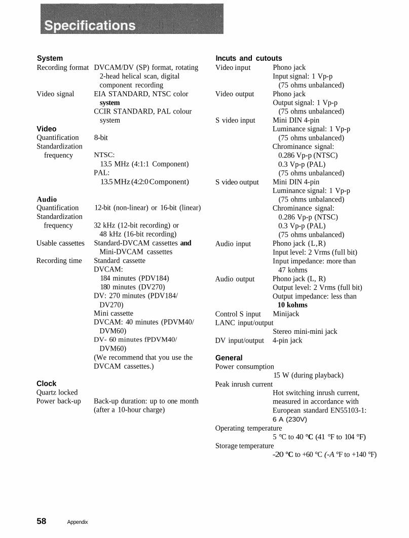
System Incuts and cutoutsRecording format DVCAM/DV (SP) format, rotating
2-head helical scan, digitalcomponent recording
Video input Phono jackInput signal: 1 Vp-p
(75 ohms unbalanced)Video signal EIA STANDARD, NTSC color Video output Phono jack
system Output signal: 1 Vp-pCCIR STANDARD, PAL colour (75 ohms unbalanced)
systemVideoQuantificationStandardization
8-bit
Mini DIN 4-pinLuminance signal: 1 Vp-p
(75 ohms unbalanced)
S video input
Chrominance signal:frequency NTSC:
13.5 MHz (4:1:1 Component)PAL:
0.286 Vp-p (NTSC)0.3 Vp-p (PAL)(75 ohms unbalanced)
13.5 MHz (4:2:0 Component) S video output Mini DIN 4-pinLuminance signal: 1 Vp-p
Audio (75 ohms unbalanced)QuantificationStandardization
frequency
12-bit (non-linear) or 16-bit (linear)
32 kHz (12-bit recording) or48 kHz (16-bit recording)
Chrominance signal:0.286 Vp-p (NTSC)0.3 Vp-p (PAL)(75 ohms unbalanced)
Usable cassettes Standard-DVCAM cassettes andMini-DVCAM cassettes
Recording time Standard cassetteDVCAM:
Phono jack (L,R)Input level: 2 Vrms (full bit)Input impedance: more than
Audio input
47 kohms184 minutes (PDV184)180 minutes (DV270)
DV: 270 minutes (PDV184/
Audio output Phono jack (L, R)Output level: 2 Vrms (full bit)Output impedance: less than
DV270) 10 kohmsMini cassetteDVCAM: 40 minutes (PDVM40/
Control S input MinijackLANC input/output
DVM60)DV- 60 minutes fPDVM40/
Stereo mini-mini jack4-pin jackDV input/output
DVM60)(We recommend that you use theDVCAM cassettes.)
GeneralPower consumption
15 W (during playback)ClockQuartz lockedPower back-up Back-up duration: up to one month
(after a 10-hour charge)
Peak inrush currentHot switching inrush current,measured in accordance withEuropean standard EN55103-1:6 A (230V)
Operating temperature5 °C to 40 °C (41 °F to 104 °F)
Storage temperature-20 °C to +60 °C (-A °F to +140 °F)
58 Appendix
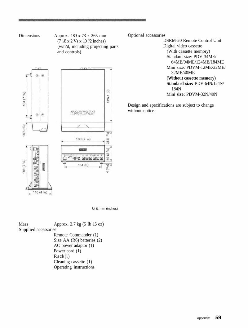
Dimensions Approx. 180 x 73 x 265 mm(7 !/8 x 2 Vs x 10 '/2 inches)(w/h/d, including projecting partsand controls)
Optional accessoriesDSRM-20 Remote Control UnitDigital video cassette
(With cassette memory)Standard size: PDV-34ME/
64ME/94ME/124ME/184MEMini size: PDVM-12ME/22ME/
32ME/40ME(Without cassette memory)Standard size: PDV-64N/124N/
184NMini size: PDVM-32N/40N
Design and specifications are subject to changewithout notice.
Unit: mm (inches)
Mass Approx. 2.7 kg (5 Ib 15 oz)Supplied accessories
Remote Commander (1)Size AA (R6) batteries (2)AC power adaptor (1)Power cord (1)Rack(l)Cleaning cassette (1)Operating instructions
59Appendix

Audio recording modeIn the DVCAM format, the sound isrecorded in either 16bit (Fs48k) or 12bit(Fs32k) mode.
Component signalA video signal consisting of a luminancesignal (Y) and two chrominance signals(R-Y,B-Y).
CondensationCondensation of moisture on the tapetransport mechanisms of VCRs includingthe head drum. If moisture condenses onthe head drum, the tape adheres to thedrum and causes malfunction.
Drop frame modeIn NTSC format, the actual number offrames per second is approximately 29.97,while that for SMPTE time code isspecified as 30. Drop frame mode is amode in which time code is advanced insuch a way that the difference in framevalue between real time and time code iscorrected. In this mode, two frames areskipped at the beginning of each minute,except for every tenth minute, so that theframe value for time code matches that forreal time. See also "Non-drop framemode."
DrumSee "Head drum."
EE modeEE is an abbreviation of "Electric toElectric." Video and audio signals aresupplied to the VCR'S internal circuits, butnot to the recording heads.
Head drumA metal cylinder to which video heads areattached. During recording and playback,the drum rotates at high speeds insynchronization with the sync signal.
LoadingWhen being loaded, the tape is pulled outof the cassette case and threaded along thespecified tape path and wrapped round thedrum to be ready for recording orplayback. Generally, this is doneautomatically when you place the cassetteat the cassette entrance of the VCR. Alsocalled threading.
Non-drop frame modeA mode of advancing time code in such away that the difference in frame valuebetween real time and time code isneglected. Using this mode produces adifference of approximately 86 secondsper day between real time and time code,which may cause problems when editingprograms in units of seconds using thenumber of frames as a reference.
PCM audioPCM stands for "pulse code modulation."PCM audio means audio signals that havebeen processed by pulse code modulation.Each analog audio signal is converted intopulses that are generated in rapidsuccession, and each pulse is recorded as adigital signal having a value of 0 or 1.
SearchTo locate a particular scene by running thetape in the fast forward or rewind modewhile viewing the picture or time codes.
SuperimposeTo put a set of characters onto a picture sothat both can be seen at the same time.
ThreadingSee "Loading."
Time codeSignals recorded on the tape to supplyinformation on tape position such as thehour, minute, second and frame, to assistin setting edit points or searching forparticular scenes. This unit can cope withboth DF (Drop Frame) and NDF (NonDrop Frame).On this unit, the time code is recordedsequently from "00:00:00:00;' from thebeginning of the tape. However, if there isa blank section on the tape, time code isreset and recorded from "00:00:00:00"again from the section just after the blanksection. If the time codes are out ofsequence, you may not be able to executecorrect editing.
UnloadingWhen being unloaded, the tape is put intothe cassette case from the tape path of theVCR. Generally, this is done automaticallywhen you press the EJECT button. Alsocalled unthreading.
UnthreadingSee "Unloading."
12bit (Fs32k) modeIn the DVCAM format, the 12bit (Fs32k)mode separates the audio area into 2 parts.You can record two kinds of audio, stereo1 and stereo 2.
16bit (Fs48k) modeIn the DVCAM format, the 16bit (Fs48k)mode uses the whole audio area to recordone stereo track. You can get higher soundquality.
Appendix60
AC timer.....Audio modeAuto Repeat
3244
32
Menu.............................Mini-DVCAM cassette.
Non Drop Frame, 60
.27
4115
Camera data........Cassette memoryCleaning..............Clock ..................
25315249
16
Photo search ...............Playback
29
2828
at various speeds .................frame by frame....................
Date search ..................Drop Frame..................DV
2960
Remote Commander. 13
DVCAM
56551134
5655
Searching using search function...Standard DVCAM cassette...........
cassette ...................format.....................IN/OUT connector .
20
156
cassetteformat.
2915
454929
27Tape remaining time ...Time code ...................Fs32k
Fs48k4444 Title search .................
i.LINK ....................................Index search............................
Unlock mode ............................Usable cassette ..........................
1129
5515
LANCjack ... 11 22 36Lock mode.................................... 55
Appendix 61