digital signal processing: signals, systems, and …dsp/erratadsp.pdf · digital signal processing:...
TRANSCRIPT

DIGITAL SIGNAL PROCESSING: Signals, Systems, and Filters
Andreas Antoniou
Errata Corrections for Printings #1 and #2
(Revision date: July 1, 2015)
NOTE:
I would greatly appreciate to be notified of any typographical errors in the textbook, the slides forthe textbook, and the solutions of the end-of-chapter problems found at this website. Comments andsuggestions for the next edition are especially welcome.
Author
Preface
� Page xxiii Replace line �7 (a negative number indicates lines from the bottom ofthe page) by the following:
between pages 454 and 455 for more details. The software can be downloaded from thetextbook’s website:
Chapter 2
� Page 58 The reference citation just after Theorem 2.5 should read as follows:
(See pp. 9 and 29–30 of [5].)
� Page 72 Table 2.1, column 2, replace a by ˛ in the bottom two entries, as follows:
1
˛ C j!
!0
.˛ C j!/2 C !20
� Page 75 Prob. 2.12, part (a), should read as follows:
(a) x.t/ D ˛t for � �0=2 � t � �0=2
� Page 75 Prob. 2.13, part (b), should read as follows:
(b) x.t/ D
(0 for ��0=2 � t < 0
sin!0t for 0 � t � �0=2
� Page 75 Prob. 2.16, part (a), should read as follows:
(a) X.�j!/ D X�.j!/
� Page 75 Prob. 2.17, parts (b) and (c), should read as follows:
(b) Assuming that x.t/ is purely imaginary and an even function of time, show thatRe X.j!/ D
0 and Im X.j!/ is an even function of frequency.
(c) Assuming that x.t/ is purely imaginary and an odd function of time, show that Im X.j!/ D
0 and Re X.j!/ is an odd function of frequency.
� Page 76 Prob. 2.23, parts (a) and (b), should read as follows:
(a) X2.j!/ D X�.�j!/
(b) X2.�j!/ D X�.j!/
� Page 76 Prob. 2.25, part (b), should read as follows:
(b) Sketch the waveform of
x2.t/ D
1XnD�1
x1.t � nT /
assuming that T > � .
2 DIGITAL SIGNAL PROCESSING: Signals, Systems, and Filters
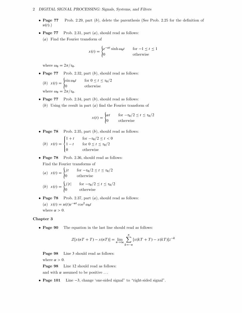
� Page 77 Prob. 2.29, part (b), delete the parenthesis (See Prob. 2.25 for the definition ofu.t/.)
� Page 77 Prob. 2.31, part (a), should read as follows:
(a) Find the Fourier transform of
x.t/ D
(e�at sinh!0t for �1 � t � 1
0 otherwise
where !0 D 2�=�0.
� Page 77 Prob. 2.32, part (b), should read as follows:
(b) x.t/ D
(sin!0t for 0 � t � �0=2
0 otherwise
where !0 D 2�=�0.
� Page 77 Prob. 2.34, part (b), should read as follows:
(b) Using the result in part (a) find the Fourier transform of
x.t/ D
(˛t for ��0=2 � t � �0=2
0 otherwise
� Page 78 Prob. 2.35, part (b), should read as follows:
(b) x.t/ D
8̂<̂:
1 C t for ��0=2 � t < 0
1 � t for 0 � t � �0=2
0 otherwise
� Page 78 Prob. 2.36, should read as follows:
Find the Fourier transforms of
(a) x.t/ D
(jt for ��0=2 � t � �0=2
0 otherwise
(b) x.t/ D
(j jt j for ��0=2 � t � �0=2
0 otherwise
� Page 78 Prob. 2.37, part (a), should read as follows:
(a) x.t/ D u.t/e�˛t cos2 !0t
where ˛ > 0.
Chapter 3
� Page 90 The equation in the last line should read as follows:
ZŒx.nT C T / � x.nT /� D limn!1
nXkD�n
Œx.kT C T / � x.kT /�z�k
Page 98 Line 3 should read as follows:
where ˛ > 0.
Page 98 Line 12 should read as follows:
and with ˛ assumed to be positive : : :
� Page 101 Line �3, change ‘one-sided signal” to “right-sided signal”.
Errata Corrections for Printings #1 and #2 3
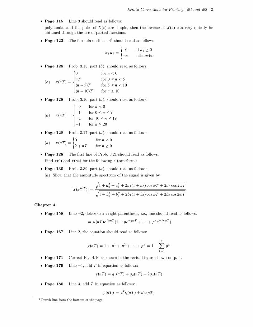
� Page 115 Line 3 should read as follows:
polynomial and the poles of X.z/ are simple, then the inverse of X.z/ can very quickly beobtained through the use of partial fractions.
� Page 123 The formula on line �41 should read as follows:
arg a1 D
(0 if a1 � 0
�� otherwise
� Page 128 Prob. 3.15, part (b), should read as follows:
(b) x.nT / D
8̂̂̂<̂ˆ̂:
0 for n < 0
nT for 0 � n < 5
.n � 5/T for 5 � n < 10
.n � 10/T for n � 10
� Page 128 Prob. 3.16, part (a), should read as follows:
(a) x.nT / D
8̂̂̂<̂ˆ̂:
0 for n < 0
1 for 0 � n � 9
2 for 10 � n � 19
�1 for n � 20
� Page 128 Prob. 3.17, part (a), should read as follows:
(a) x.nT / D
(0 for n < 0
2 C nT for n � 0
� Page 128 The first line of Prob. 3.21 should read as follows:
Find x.0/ and x.1/ for the following z transforms:
� Page 130 Prob. 3.39, part (a), should read as follows:
(a) Show that the amplitude spectrum of the signal is given by
jX.ej!T /j D
q1 C a20 C a21 C 2a1.1 C a0/ cos!T C 2a0 cos 2!Tq1 C b20 C b21 C 2b1.1 C b0/ cos!T C 2b0 cos 2!T
Chapter 4
� Page 158 Line �2, delete extra right parenthesis, i.e., line should read as follows:
D u.nT /ej!nT .1 C pe�j!TC � � � C pne�jn!T /
� Page 167 Line 2, the equation should read as follows:
y.nT / D 1 C p1 C p2 C � � � C pn D 1 C
nXkD1
pk
� Page 171 Correct Fig. 4.16 as shown in the revised figure shown on p. 4.
� Page 179 Line �1, add T in equation as follows:
y.nT / D q1.nT / C q2.nT / C 2q3.nT /
� Page 180 Line 3, add T in equation as follows:
y.nT / D cT q.nT / C dx.nT /
1Fourth line from the bottom of the page.
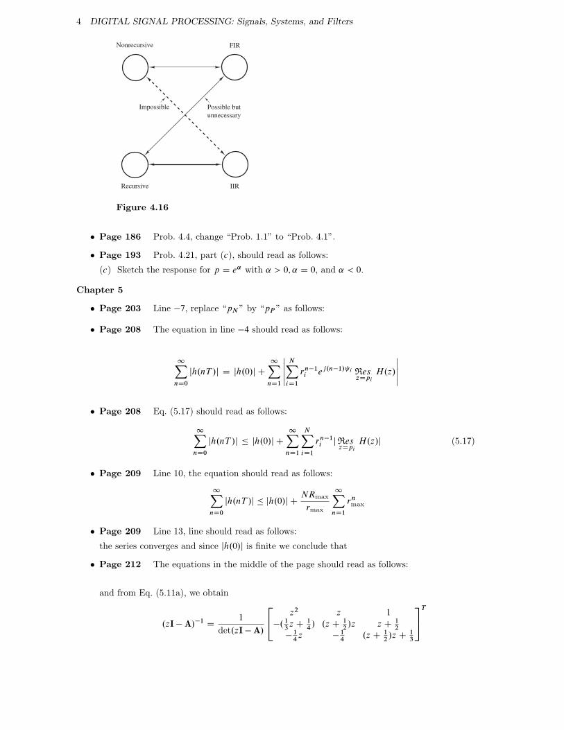
4 DIGITAL SIGNAL PROCESSING: Signals, Systems, and Filters
Nonrecursive
Recursive
FIR
IIR
Possible but
unnecessary
Impossible
Figure 4.16
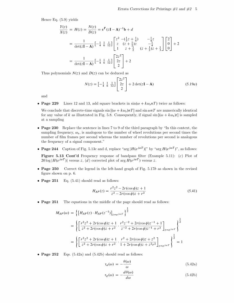
� Page 186 Prob. 4.4, change “Prob. 1.1” to “Prob. 4.1”.
� Page 193 Prob. 4.21, part (c), should read as follows:
(c) Sketch the response for p D e˛ with ˛ > 0; ˛ D 0, and ˛ < 0.
Chapter 5
� Page 203 Line �7, replace “pN ” by “pP ” as follows:
� Page 208 The equation in line �4 should read as follows:
1XnD0
jh.nT /j D jh.0/j C
1XnD1
ˇ̌̌̌ˇNXiD1
rn�1i ej.n�1/ i Res
zDpi
H.z/
ˇ̌̌̌ˇ
� Page 208 Eq. (5.17) should read as follows:
1XnD0
jh.nT /j � jh.0/j C
1XnD1
NXiD1
rn�1i jRes
zDpi
H.z/j (5.17)
� Page 209 Line 10, the equation should read as follows:
1XnD0
jh.nT /j � jh.0/j CNRmax
rmax
1XnD1
rnmax
� Page 209 Line 13, line should read as follows:
the series converges and since jh.0/j is finite we conclude that
� Page 212 The equations in the middle of the page should read as follows:
and from Eq. (5.11a), we obtain
.zI � A/�1D
1
det.zI � A/
24 z2 z 1
�.13z C
14/ .z C
12/z z C
12
�14z �
14
.z C12/z C
13
35T
Errata Corrections for Printings #1 and #2 5
Hence Eq. (5.9) yields
Y.z/
X.z/D H.z/ D
N.z/
D.z/D cT .zI � A/�1b C d
D1
det.zI � A/
��1416
112
� 24z2 �.13z C
14/ �
14z
z .z C12/z �
14
1 z C12
.z C12/z C
13
35 242
0
0
35 C 2
D1
det.zI � A/
��1416
112
� 242z2
2z
2
35 C 2
Thus polynomials N.z/ and D.z/ can be deduced as
N.z/ D��1416
112
� 242z2
2z
2
35 C 2det.zI � A/ .5:19a/
and
� Page 229 Lines 12 and 13, add square brackets in sin.! C k!snT / twice as follows:
We conclude that discrete-time signals sin Œ.! C k!s/nT � and sin!nT are numerically identicalfor any value of k as illustrated in Fig. 5.8. Consequently, if signal sin Œ.! C k!s/t � is sampledat a sampling
� Page 230 Replace the sentence in lines 7 to 9 of the third paragraph by “In this context, thesampling frequency, !s, is analogous to the number of wheel revolutions per second times thenumber of film frames per second whereas the number of revolutions per second is analogousthe frequency of a signal component.”
� Page 244 Caption of Fig. 5.13c and d, replace “arg jH.ej!T /j” by “argH.ej!T /”, as follows:
Figure 5.13 Cont’d Frequency response of bandpass filter (Example 5.11): (c) Plot of20 log jH.ej!T /j versus z, (d ) corrected plot of argH.ej!T / versus z.
� Page 250 Correct the legend in the left-hand graph of Fig. 5.17b as shown in the revisedfigure shown on p. 6.
� Page 251 Eq. (5.41) should read as follows:
HAP .z/ Dr2z2 � 2r.cos�/z C 1
z2 � 2r.cos�/z C r2.5:41/
� Page 251 The equations in the middle of the page should read as follows:
MAP .!/ D
n �HAP .z/ � HAP .z�1/
�zDej!T
o12
D
( �r2z2 C 2r.cos�/z C 1
z2 C 2r.cos�/z C r2�
r2z�2 C 2r.cos�/z�1 C 1
z�2 C 2r.cos�/z�1 C r2
�zDej!T
)12
D
( �r2z2 C 2r.cos�/z C 1
z2 C 2r.cos�/z C r2�
r2 C 2r.cos�/z C z2
1 C 2r.cos�/z C z2r2
�zDej!T
)12
D 1
� Page 252 Eqs. (5.42a) and (5.42b) should read as follows:
�a.!/ D ��.!/
!(5.42a)
�g.!/ D �d�.!/
d!(5.42b)
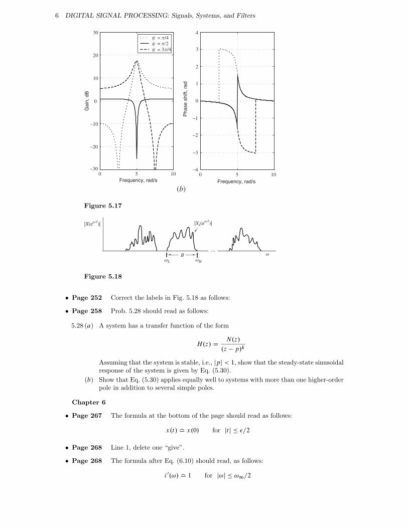
6 DIGITAL SIGNAL PROCESSING: Signals, Systems, and Filters
0 5 10−30
−20
−10
0
10
20
30
Frequency, rad/s
Ga
in, d
B
ψ = π/4
ψ = π/2
ψ = 3π/4
0 5 10−4
−3
−1
0
1
2
3
4
Frequency, rad/sP
ha
se
sh
ift, r
ad
−2
(b)
Figure 5.17
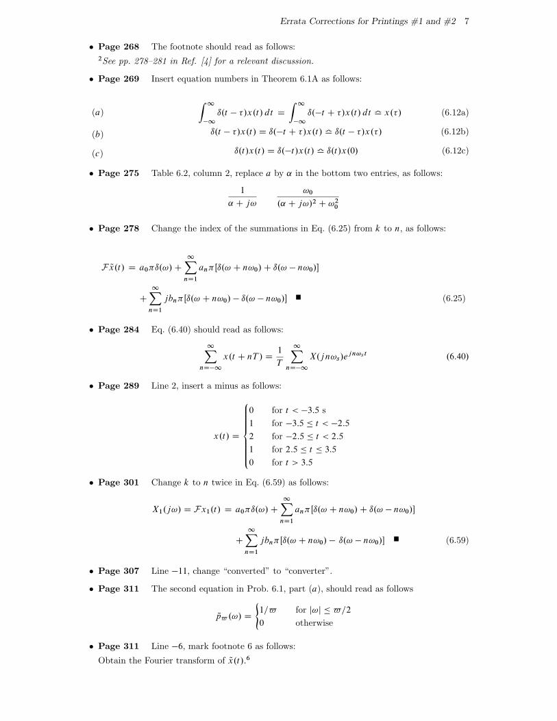
ωL ωH
|X(ejωT)| |Xk(ejωT)|
B ω
Figure 5.18
� Page 252 Correct the labels in Fig. 5.18 as follows:
� Page 258 Prob. 5.28 should read as follows:
5.28 (a) A system has a transfer function of the form
H.z/ DN.z/
.z � p/k
Assuming that the system is stable, i.e., jpj < 1, show that the steady-state sinusoidalresponse of the system is given by Eq. (5.30).
(b) Show that Eq. (5.30) applies equally well to systems with more than one higher-orderpole in addition to several simple poles.
Chapter 6
� Page 267 The formula at the bottom of the page should read as follows:
x.t/ l x.0/ for jt j � �=2
� Page 268 Line 1, delete one “give”.
� Page 268 The formula after Eq. (6.10) should read, as follows:
i 0.!/ l 1 for j!j � !1=2
Errata Corrections for Printings #1 and #2 7
� Page 268 The footnote should read as follows:2See pp. 278–281 in Ref. [4] for a relevant discussion.
� Page 269 Insert equation numbers in Theorem 6.1A as follows:
(a)
Z 1
�1
ı.t � �/x.t/ dt D
Z 1
�1
ı.�t C �/x.t/ dt l x.�/ (6.12a)
(b) ı.t � �/x.t/ D ı.�t C �/x.t/ l ı.t � �/x.�/ (6.12b)
(c) ı.t/x.t/ D ı.�t /x.t/ l ı.t/x.0/ (6.12c)
� Page 275 Table 6.2, column 2, replace a by ˛ in the bottom two entries, as follows:
1
˛ C j!
!0
.˛ C j!/2 C !20
� Page 278 Change the index of the summations in Eq. (6.25) from k to n, as follows:
F Qx.t/ D a0�ı.!/ C
1XnD1
an�Œı.! C n!0/ C ı.! � n!0/�
C
1XnD1
jbn�Œı.! C n!0/ � ı.! � n!0/� (6.25)
� Page 284 Eq. (6.40) should read as follows:
1XnD�1
x.t C nT / D1
T
1XnD�1
X.jn!s/ejn!s t .6:40/
� Page 289 Line 2, insert a minus as follows:
x.t/ D
8̂̂̂̂ˆ̂<̂ˆ̂̂̂̂:
0 for t < �3:5 s
1 for �3:5 � t < �2:5
2 for �2:5 � t < 2:5
1 for 2:5 � t � 3:5
0 for t > 3:5
� Page 301 Change k to n twice in Eq. (6.59) as follows:
X1.j!/ D Fx1.t/ D a0�ı.!/ C
1XnD1
an�Œı.! C n!0/ C ı.! � n!0/�
C
1XnD1
jbn�Œı.! C n!0/ � ı.! � n!0/� (6.59)
� Page 307 Line �11, change “converted” to “converter”.
� Page 311 The second equation in Prob. 6.1, part (a), should read as follows
Np$ .!/ D
(1=$ for j!j � $=2
0 otherwise
� Page 311 Line �6, mark footnote 6 as follows:
Obtain the Fourier transform of Qx.t/:6
8 DIGITAL SIGNAL PROCESSING: Signals, Systems, and Filters
� Page 311 Insert the following footnote at the bottom of the page:6In Probs. 6.2–6.7, assume that T > � or �0.
� Page 315 The third line of Prob. 6.21, part (a), should read as follows:
where � D .N � 1/T and N is odd. The sampling frequency is !s D 2�=T .
� Page 315 The equation in Prob. 6.22 should read as follows:
x.t/ D
8<:˛ C .1 � ˛/ cos2�t
�for jt j � �=2
0 otherwise
where � D .N � 1/T .
� Page 317 Line 1, insert “transform” after Fourier as follows:
Obtain the Fourier transform of
� Page 317 Line 6, replace “ !s � 16=�N ” by “N � 4=�” twice, as follows:
if N � 4=� . (Hint: Note that X.j!/ ! 0 if N � 4=� .)
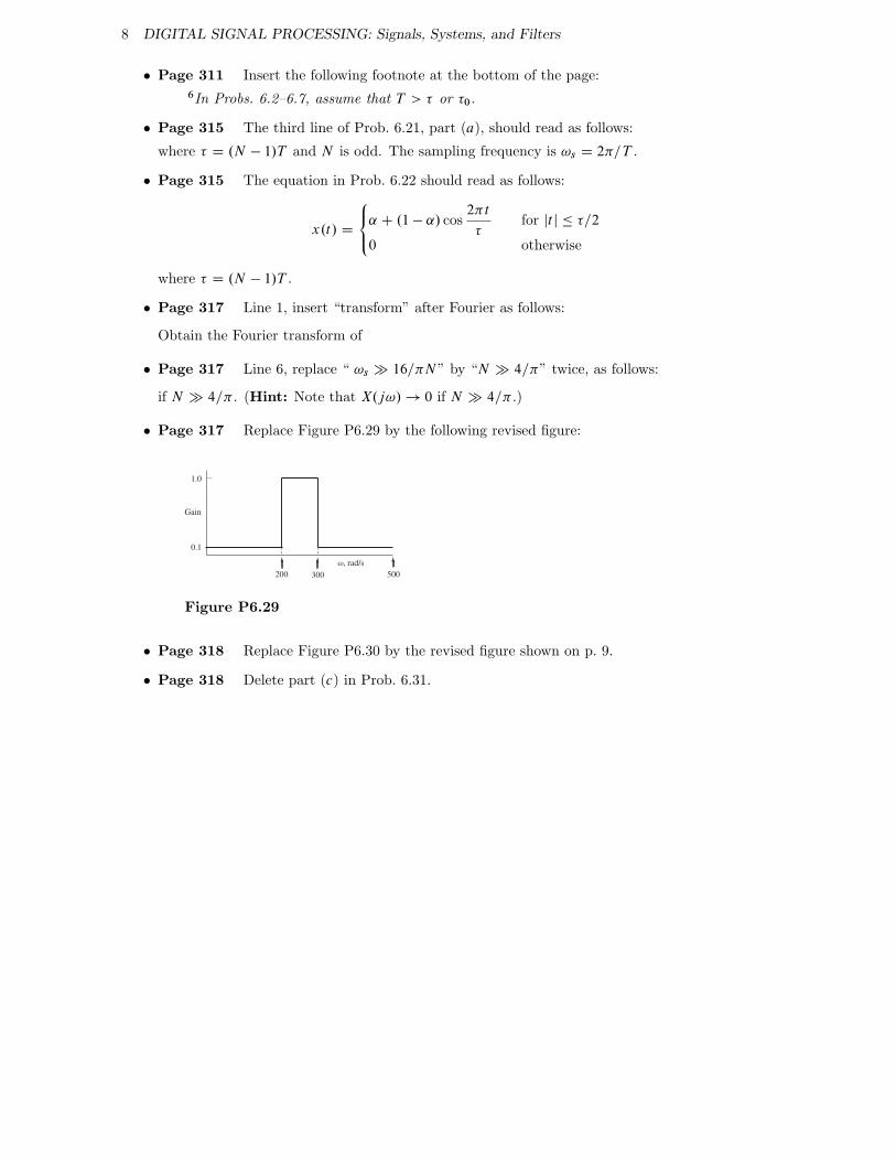
� Page 317 Replace Figure P6.29 by the following revised figure:
0.1
1.0
Gain
200 300 500
ω, rad/s
Figure P6.29
� Page 318 Replace Figure P6.30 by the revised figure shown on p. 9.
� Page 318 Delete part (c) in Prob. 6.31.
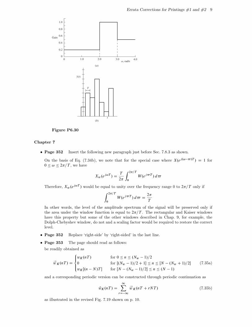
Errata Corrections for Printings #1 and #2 9
(b)t
T
y(t)
0.2
0.4
0.6
0.8
1.0
1.00
0 2.0 3.0 4.0ω, rad/s
(a)
Gain
~
Figure P6.30
Chapter 7
� Page 352 Insert the following new paragraph just before Sec. 7.8.3 as shown.
On the basis of Eq. (7.34b), we note that for the special case where X.ej.!�$/T / D 1 for0 � ! � 2�=T , we have
Xw.ej!T / DT
2�
Z 2�=T
0
W.ej$T / d$
Therefore, Xw.ej!T / would be equal to unity over the frequency range 0 to 2�=T only ifZ 2�=T
0
W.ej$T / d$ D2�
T
In other words, the level of the amplitude spectrum of the signal will be preserved only ifthe area under the window function is equal to 2�=T . The rectangular and Kaiser windowshave this property but some of the other windows described in Chap. 9, for example, theDolph-Chebyshev window, do not and a scaling factor would be required to restore the correctlevel.
� Page 352 Replace ‘right-side’ by ‘right-sided’ in the last line.
� Page 353 The page should read as follows:
be readily obtained as
!wK.nT / D
8̂<̂:
wK.nT / for 0 � n � .Nw � 1/=2
0 for Œ.Nw � 1/=2 C 1� � n � ŒN � .Nw C 1/=2�
wK Œ.n � N /T � for ŒN � .Nw � 1/=2� � n � .N � 1/
(7.35a)
and a corresponding periodic version can be constructed through periodic continuation as
QwK.nT / D
1XrD�1
!wK.nT C rNT / (7.35b)
as illustrated in the revised Fig. 7.19 shown on p. 10.
10 DIGITAL SIGNAL PROCESSING: Signals, Systems, and Filters
N
N
2N
2N
(a)
(b)
(c)
(Nw−1)/2
(Nw−1)/2
(Nw−1)/2
−(Nw−1)/2
wK(nT)
wK(nT)
→
wK(nT)
∼
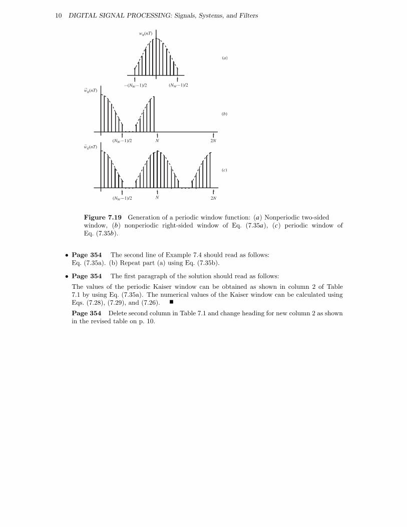
Figure 7.19 Generation of a periodic window function: (a) Nonperiodic two-sidedwindow, (b) nonperiodic right-sided window of Eq. (7.35a), (c) periodic window ofEq. (7.35b).
� Page 354 The second line of Example 7.4 should read as follows:Eq. (7.35a). (b) Repeat part (a) using Eq. (7.35b).
� Page 354 The first paragraph of the solution should read as follows:
The values of the periodic Kaiser window can be obtained as shown in column 2 of Table7.1 by using Eq. (7.35a). The numerical values of the Kaiser window can be calculated usingEqs. (7.28), (7.29), and (7.26).
Page 354 Delete second column in Table 7.1 and change heading for new column 2 as shownin the revised table on p. 10.
Errata Corrections for Printings #1 and #2 11
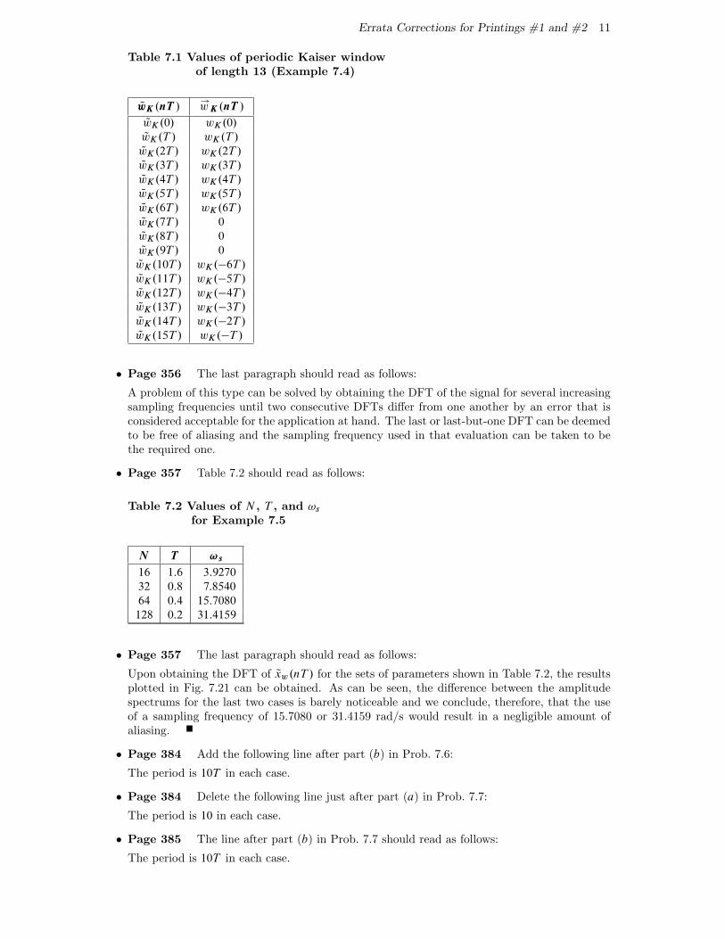
Table 7.1 Values of periodic Kaiser windowof length 13 (Example 7.4)
QwK .nT /!wK .nT /
QwK.0/ wK.0/
QwK.T / wK.T /
QwK.2T / wK.2T /
QwK.3T / wK.3T /
QwK.4T / wK.4T /
QwK.5T / wK.5T /
QwK.6T / wK.6T /
QwK.7T / 0
QwK.8T / 0
QwK.9T / 0
QwK.10T / wK.�6T /
QwK.11T / wK.�5T /
QwK.12T / wK.�4T /
QwK.13T / wK.�3T /
QwK.14T / wK.�2T /
QwK.15T / wK.�T /
� Page 356 The last paragraph should read as follows:
A problem of this type can be solved by obtaining the DFT of the signal for several increasingsampling frequencies until two consecutive DFTs differ from one another by an error that isconsidered acceptable for the application at hand. The last or last-but-one DFT can be deemedto be free of aliasing and the sampling frequency used in that evaluation can be taken to bethe required one.
� Page 357 Table 7.2 should read as follows:
Table 7.2 Values of N , T , and !sfor Example 7.5
N T !s
16 1:6 3:9270
32 0:8 7:8540
64 0:4 15:7080
128 0:2 31:4159
� Page 357 The last paragraph should read as follows:
Upon obtaining the DFT of Qxw.nT / for the sets of parameters shown in Table 7.2, the resultsplotted in Fig. 7.21 can be obtained. As can be seen, the difference between the amplitudespectrums for the last two cases is barely noticeable and we conclude, therefore, that the useof a sampling frequency of 15.7080 or 31.4159 rad/s would result in a negligible amount ofaliasing.
� Page 384 Add the following line after part (b) in Prob. 7.6:
The period is 10T in each case.
� Page 384 Delete the following line just after part (a) in Prob. 7.7:
The period is 10 in each case.
� Page 385 The line after part (b) in Prob. 7.7 should read as follows:
The period is 10T in each case.
12 DIGITAL SIGNAL PROCESSING: Signals, Systems, and Filters
� Page 385 Prob. 7.8 should read as follows:
7.8. Find the DFTs of the following periodic signals in closed form:
(a) Qx.nT / D e�ˇn for 0 � n � 31 if N D 32.
(b) Repeat part (a) for Qx.nT / D e� n=2� for 0 � n � 31 if N D 32.
� Page 385 Prob. 7.16 should read as follows:
7.16. Construct Table 7.1 for a Kaiser window of length 31 for a 32-point DFT.
� Page 386 Part (a) for Prob. 7.19 should read as follows:
(a) Obtain an approximate expression for WTR.ej!T /.
� Page 386 Probs. 7.20–7.23 should read as follows:
7.20. An infinite duration discrete-time signal is described by
x.nT / D u.nT /�A0e
p0nT C 2M1e�1nT cos.!1nT C �1/
�where A0 D 4:532, M1 D 2:350, �1 D �2:873 rad, p0 D �0:05, �1 D �0:5, and !1 D
1:754.
(a) Obtain an expression for the frequency spectrum of the signal.
(b) Plot the amplitude spectrum over the range 0 � ! � !s=2 assuming a samplingfrequency !s D 10 rad/s.
(c) Repeat part (b) if the signal is truncated through the use of a rectangular window oflength 31.
(d ) Repeat part (b) if the signal is truncated through the use of a Kaiser window oflength 31 and ˛ D 1:0.
(e) Compare the results obtained in parts (c) and (d ).
7.21. An infinite-duration right-sided discrete-time signal x.nT / is obtained by sampling thecontinuous-time signal
x.t/ D u.t/�A0e
p0t C 2M1e�1t cos.!1t C �1/
�where A0 D 5:0, M1 D 3:0, �1 D �2:556 rad, p0 D �2:0, �1 D �1:5, and !1 D 2:5. Afinite duration signal can be obtained by applying the discrete-time Kaiser window with˛ D 2:0. Following the approach in Example 7.5, find the lowest sampling frequency thatwould result in negligible aliasing error.
7.22. Repeat Prob. 7.21 if A0 D 5:0, M1 D 3:0, �1 D �2:556 rad, p0 D �0:05, �1 D �0:5,!1 D 2:5, and ˛ D 3:0.
7.22. Prove Theorem 7.2B.
� Page 386 The first line of Prob. 7.25 should read as follows:
(a) Two periodic signals are given by
� Page 387 Replace Prob. 7.26 by the following new problem:
7.26 Two periodic signals x.n/ and h.n/ can be represented by
x.n/ D
1XrD�1
x0.n C 10r/ and h.n/ D
1XrD�1
h0.n C 10r/
where
x0.n/ D
8̂<̂:
�˛n for �5 � n � 0
˛n for 0 � n � 5
0 otherwise
and
h0.n/ D
(1 for n D �2; �1; 1; 2
0 otherwise
Find the periodic convolution of x.n/ and h.n/ at n D 6.
Errata Corrections for Printings #1 and #2 13
Chapter 8
� Page 402 Eqs. (8.8c) and (8.8d) should read as follows:
Nj�1.z/ D Nj .z/ � �jPj .z/ D
j�1XiD0
˛.j�1/iz�i .8:8c/
Dj�1.z/ DDj .z/ � �jPj .z/
1 � �2jD
j�1XiD0
ˇ.j�1/iz�i .8:8d/
� Page 406 Line �3 Add missing z in equation as follows:
D 9 �1
1 C12z�1
�1 C
49z�1 C
19z�2
1 C712
z�1 C112
z�2
� Page 408 Line 2, change a plus to a minus sign in the equation as follows:
H.z/ D10z4 � 3:7z3 � 1:28z2 C 0:99z
.z2 � z C 0:34/.z2 C 0:9z C 0:2/
� Page 408 In Example 8.5, the transfer function of the filter should be
H.z/ D10z4 � 3:7z3 � 1:28z2 C 0:99z
.z2 � z C 0:34/.z2 C 0:9z C 0:2/
i.e., the coefficient of z in the first quadratic factor in the denominator should be �1.
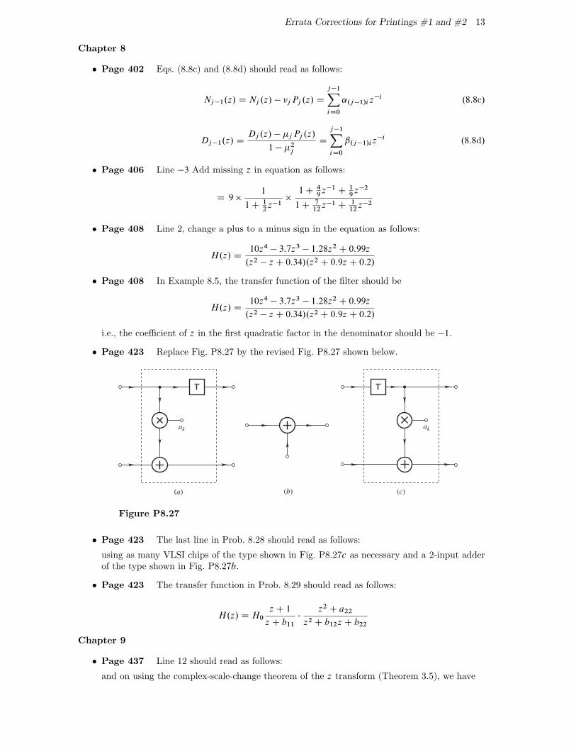
� Page 423 Replace Fig. P8.27 by the revised Fig. P8.27 shown below.
(a) (b)
+
ak
(c)
+
ak
Figure P8.27
� Page 423 The last line in Prob. 8.28 should read as follows:
using as many VLSI chips of the type shown in Fig. P8.27c as necessary and a 2-input adderof the type shown in Fig. P8.27b.
� Page 423 The transfer function in Prob. 8.29 should read as follows:
H.z/ D H0
z C 1
z C b11�
z2 C a22
z2 C b12z C b22
Chapter 9
� Page 437 Line 12 should read as follows:
and on using the complex-scale-change theorem of the z transform (Theorem 3.5), we have
14 DIGITAL SIGNAL PROCESSING: Signals, Systems, and Filters
� Page 441 The formula for the kth-order Chebyshev polynomial should read as follows:
Tk.x/ D
(cos.k cos�1 x/ for jxj � 1
cosh.k cosh�1 x/ for jxj > 1
� Page 443 Eq. (9.24) and the line before it should read as follows:
and hence we get
h.nT / D
8̂̂<̂:̂
1 �2!c
!sfor n D 0
�1
n�sin!cnT otherwise
.9:24/
� Page 448 The specifications for Example 9.4 should read as follows:
� Maximum passband ripple in frequency range 0 to 3.0 rad/s: 0.1 dB
� Minimum stopband attenuation in frequency range 5.0 to 10.0 rad/s: 40 dB
� Sampling frequency: 20 rad/s
� Page 452 The equations for h.nT / and the line that follows should read as follows:
h.nT / D1
!s
�Z �!c1
�!c2
ej!nT d! C
Z !c2
!c1
ej!nT d!
�D
1
!s
�e�j!c1nT
jnT�
e�j!c2nT
jnTC
ej!c2nT
jnT�
ej!c1nT
jnT
�D
1
n�
�ej!c2nT � e�j!c2nT
2j�
ej!c1nT � e�j!c2nT
2j
�D
1
n�.sin!c2nT � sin!c1nT /
where h.0/ D 2.!c2 � !c1/=!s. Now according to step 2,
� Page 459 In Prob. 9.3, change the second “(a)” to “(b)”.
� Page 460 In Prob. 9.4, change the second “(a)” to “(b)”.
� Page 461 Prob. 9.12, part (b), should read as follows:
(b) Assuming that the passband extends from 3.8 to 6.2 rad/s modify the design in part (a)so as to achieve an amplitude response that oscillates about unity.
� Page 461 Prob. 9.13 should read as follows:
(a) Repeat Prob. 9.12 assuming a ripple ratio of �25 dB, a passband that extends from 3.91to 6.09 rad/s, and stopbands that extend from 0 to 2.0 and 8.0 to 10 rad/s.
(b) Compare the design of this problem with that of Prob. 9.12.
� Page 462 Delete part (c) in Prob. 9.20.
Chapter 10
� Page 489 Replace D.s/ by D0.s/ in Eqs. (10.37a) and (10.37b).
� Page 497 The line after Eq. (10.58) should read as follows:
are the selectivity constant and discrimination constant, respectively. The loss is given by
� Page 513 Replace line 4 by the following line
only objective in the approximations described is to achieve a specific loss characteristic, there
Errata Corrections for Printings #1 and #2 15
� Page 513 Replace B.s/ by B.�/ in line 11.
� Page 516 The equation should read as follows:
HLP .Ns/ D HN .s/
ˇ̌̌̌sD�Ns
� Page 520 The first line of Prob. 10.4 should read as follows:
10.4 Filter specifications are often described pictorially as in Fig. P10.4, where !p and !a arethe desired passband
� Page 522 The first line of Prob. 10.13 should read as follows:
A fourth-order normalized lowpass inverse-Chebyshev filter with a minimum stopband loss of40 dB is required.
� Page 523 Prob. 10.17 should read as follows:
In a particular application an elliptic lowpass filter is required. The specifications are
� Selectivity k: 0.6
� Maximum passband loss Ap: 0.5 dB
� Minimum stopband loss Aa: 40.0 dB
(a) Determine the order of the transfer function.
(b) Determine the minimum stopband loss.
(c) Obtain the transfer function.
� Page 523 Prob. 10.18 should read as follows:
An elliptic lowpass filter satisfying the specifications
� Selectivity k: 0.95
� Maximum passband loss Ap: 0.3 dB
� Minimum stopband loss Aa: 60.0 dB
is required.
(a) Determine the order of the transfer function.
(b) Determine the minimum stopband loss.
(c) Obtain the transfer function.
� Page 525 Prob. 10.27, part (a), replace B0 by B .
� Page 525 Prob. 10.28, part (a), replace B0 by B .
� Page 526 Prob. 10.38, replace the second “Lower stopband edge” by “Upper stopbandedge”.
� Page 527 Prob. 10.43, replace the second “Lower stopband edge” by “Upper stopbandedge”.
� Page 527 Prob. 10.43, replace the second “Lower stopband edge” by “Upper stopbandedge”.
Chapter 11
� Page 545 The first line in Sec. 11.6.3 should read as follows:
Let ! and ˝ be the frequency variables in the analog filter and the derived digital filter,
16 DIGITAL SIGNAL PROCESSING: Signals, Systems, and Filters
� Page 556 The value of parameter R1 in Prob. 11.4 should be as follows:
R1 D �2:26 � j 0:624
� Page 558 Prob. 11.12, part (a), should read as follows:
(a) Redesign the filter of Prob. 11.5 by employing the invariant sinusoid-response method(see Prob. 11.11). The value of !0 may be assumed to be 1 rad/s.
Chapter 12
� Page 572 Line 3, replace “tan˝T=2” by “tan.˝T=2/”.
� Page 572 Line 11, replace!p
!p� K2
by!p
!a� K2
� Page 572 Line �10, replace “˝a1 � ˝a1” by “˝a1 � Q̋a1”.
Chapter 14
� Page 622 Line 8 should read as follows:
system (i.e., �8=8 in Table 14.1) but not in the other two.
� Page 645 The paragraph after Eq. (14.48) should read as follows:
In the case of parallel or cascade realizations, efficient scaling can be accomplished by usingone scaling multiplier at the input of each section and, if necessary, one at the output of therealization to maximize the output level.
� Page 646 The equations for �0, �1; : : :, should read as follows:
�0 D1
max .kF 01k1; kF1k1/
�1 D1
�0max .kF1F02k1; kF1F2k1/
�2 D1
�0�1max .kF1F2F03k1; kF1F2F3k1/
�3 D1
�0�1�2kF1F2F3k1
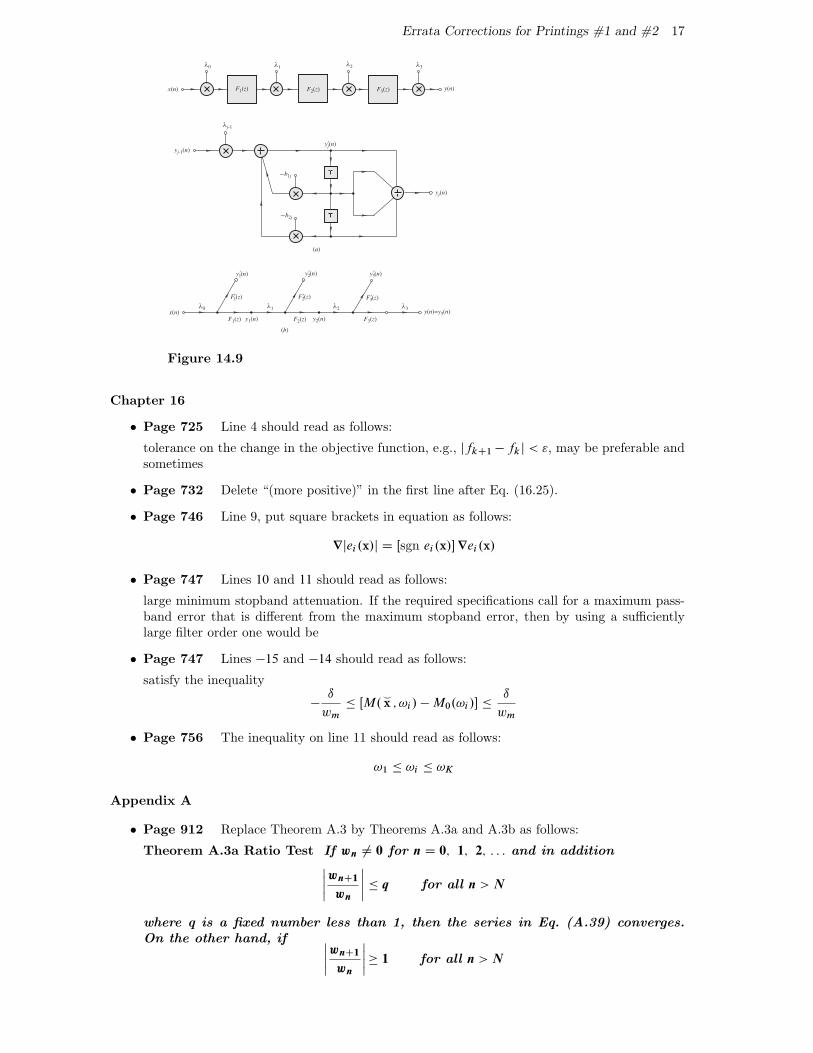
� Page 646 Replace Fig. 14.9 by the revised figure shown below.
� Page 656 Line �7, the formula should read as follows:
� D cos�1 b1
2p
b0
� Page 672 In Prob. 14.26, replace references to Prob. 11.13 and Prob. 11.18 by Prob. 14.13and Prob. 14.18, respectively.
Chapter 15
� Page 698 Caption of Fig. 15.5, change “gain” to “error”.
� Page 699 Caption of Fig. 15.6, change “gain” to “error”.
� Page 703 Caption of Fig. 15.7, change “gain” to “error”.
� Page 704 Eq. (15.54) should read as follows:
P 0c.!/ D .sin!/Pc�1.!/ .15:54/
� Page 714 Caption of Fig. 15.10, change “gain” to “error”.
Errata Corrections for Printings #1 and #2 17
λ0 λ1λ2 λ3
y1′(n) y2
′(n)
F2′(z)F 1
′(z) F3′(z)
y2(n)F2(z)F1(z) F3(z)y1(n)
y(n)=y3(n)
y3′(n)
y(n)
x(n)
x(n)
(b)
(a)
yj-1(n)
λj-1
yj′(n)
yj(n)
−b1j
−b2j
F1(z) F2(z) F3(z)
λ0 λ1 λ3λ2
Figure 14.9
Chapter 16
� Page 725 Line 4 should read as follows:
tolerance on the change in the objective function, e.g., jfkC1 � fkj < ", may be preferable andsometimes
� Page 732 Delete “(more positive)” in the first line after Eq. (16.25).
� Page 746 Line 9, put square brackets in equation as follows:
r jei .x/j D Œsgn ei .x/� rei .x/
� Page 747 Lines 10 and 11 should read as follows:
large minimum stopband attenuation. If the required specifications call for a maximum pass-band error that is different from the maximum stopband error, then by using a sufficientlylarge filter order one would be
� Page 747 Lines �15 and �14 should read as follows:
satisfy the inequality
�ı
wm� ŒM.
^x ; !i / � M0.!i /� �
ı
wm
� Page 756 The inequality on line 11 should read as follows:
!1 � !i � !K
Appendix A
� Page 912 Replace Theorem A.3 by Theorems A.3a and A.3b as follows:
Theorem A.3a Ratio Test If wn ¤ 0 for n D 0; 1; 2; : : : and in additionˇ̌̌̌wnC1
wn
ˇ̌̌̌� q for all n > N
where q is a fixed number less than 1, then the series in Eq. (A.39) converges.On the other hand, if ˇ̌̌̌
wnC1
wn
ˇ̌̌̌� 1 for all n > N
18 DIGITAL SIGNAL PROCESSING: Signals, Systems, and Filters
then the series diverges. NTheorem A.3b Root Test If
np
jwnj � q for all n > N
where q is a fixed number less than 1, then the series in Eq. (A.39) converges.On the other hand, if
np
jwnj� 1 for all n > N
then the series diverges. N
� Page 920 Line 9, replace “can obtained” by “can be obtained”.
� Page 920 Line 13, replace “can obtained” by “can be obtained”.
� Page 922 Line �3, replace “5. Inversion and scaling” by “6. Inversion and scaling”.