digital image copy-move forgery detection based on discrete...
TRANSCRIPT

Turk J Elec Eng & Comp Sci
(2018) 26: 1261 – 1277
c⃝ TUBITAK
doi:10.3906/elk-1701-275
Turkish Journal of Electrical Engineering & Computer Sciences
http :// journa l s . tub i tak .gov . t r/e lektr ik/
Research Article
Digital image copy-move forgery detection based on discrete fractional wavelet
transform
Amanjot Kaur LAMBA, Neeru JINDAL∗, Sanjay SHARMADepartment of Electronics and Communication, Thapar University, Patiala, India
Received: 27.01.2017 • Accepted/Published Online: 03.04.2018 • Final Version: 30.05.2018
Abstract: With the advancement of sophisticated cameras and image editing software tools, digital image tampering
techniques are frequently used without leaving visual cues behind. Digital image copy-move forgery is a kind of image
manipulation that involves copying and pasting of a certain section (or sections) within the same digital image. Generally,
this is done with false intentions of hiding important information or providing false information in an image. In view of
this, the focus of the present paper is to propose a discrete fractional wavelet transform-based scheme for identification
of duplicated regions in the image. The test image is split into overlapping image blocks with fixed dimensions. Then, on
each image block, discrete fractional wavelet transform is employed for the extraction of their features. All the feature
vectors are systematized in lexicographical manner followed by the block matching and block filtering steps to obtain the
replicated blocks, if any. The proposed method can detect single and multiple duplicated regions successfully. The results
are compared to existing techniques based on precision and recall parameters. Simulation results show that the proposed
forgery detection scheme can detect tampering areas even in the presence of distortions due to Gaussian blurring and
JPEG compression.
Key words: Digital forensics, image forgery, discrete fractional wavelet transforms, JPEG compression
1. Introduction
Generally, an image is considered as evidence of the occurrence of any significant event. However, due to the
evolution of powerful image manipulating tools like Photoshop, digital images can be easily tampered with to
such an extent that these techniques hardly leave any trace [1]. Image forgery or image tampering is used
in various areas such as surveillance systems, multimedia security, journalism, and scientific publications [2].
Hence, there is a dire necessity to develop a reliable and effective image manipulation detection system to
investigate the integrity as well as the authenticity of digital images.
Broadly, the classification of digital image tampering detection schemes is done in two categories, namely
active techniques and passive techniques [3]. In active schemes, prior information about an image is absolutely
necessary for authentication, which limits their application. It involves the preprocessing of images like signature
generation and watermark embedding. On the contrary, there is no need for such preprocessing methods or
prior information in the case of passive methods like copy-move forgery (CMF) and image splicing. This paper
presents the reliable detection of CMF using discrete fractional wavelet transform (DFrWT).
CMF, also known as region duplication, is one of the most widely used manipulation methods. It
includes copying a section of the digital image and pasting it onto another section belonging to the same image
∗Correspondence: [email protected]
1261

LAMBA et al./Turk J Elec Eng & Comp Sci
as shown in Figure 1. This is usually done with an objective of providing false information or to conceal some
important data in an image. After region duplication, certain postprocessing operations may be applied to the
image for concealing tampering clues like blurring, smoothing, and/or compression. This makes blind detection
more typical, but still replicated regions have some identifiable characteristics that can be used for the forgery
detection.
a b c
Figure 1. Example of CMF [4]: (a) original image; (b) forged image; (c) red-circled region is copied and pasted over
yellow-circled region.
Many copy-move forgery detection (CMFD) methods in the literature have been cast in a common
pipeline, i.e. creating overlapping blocks by division of the test image, extraction of features from each block,
matching of blocks on the basis of similar feature vectors, and, at the end, postprocessing operations to discard
outliers [4]. All these steps highlight the necessity of verifying the image integrity and authenticity. It was
observed that for the effectiveness of CMFD algorithms, feature vectors play a critical role. Discrete cosine
transform (DCT) [5,6] was used for all the image patches and its coefficients were used as feature vectors. This
method was advantageous as compared to JPEG compression and AWGN distortion, but this algorithm might
find too many matching blocks and many of them may not be really forged. In another approach, transformation-
based features [7] like log polar transform, affine transform, principal component analysis (PCA), or SVD were
used for CMFD. These methods can detect forgery with minimum false matches for images with high resolution.
However, a few small copied regions were not successfully detected.
In 2012 [8], discrete wavelet transform coefficients were used to get featured vectors. Unlike other existing
algorithms, this algorithm works even when the doctored image is truncated. A disadvantage of the method
was that it cannot detect duplicated regions with arbitrary rotations. PCA [9] and Fourier Mellin transform
[10] were used for obtaining features. These methods reduced the complexity by utilizing feature vectors of
small size. It was again needed to detect rotational and multiple forgeries in the image, so the researchers
employed multiorientation and multiresolution curvelet transform to find similar areas [11]. This technique was
reasonably robust to copy-move and rotate forgery detection. However, the performance of this method relies
on the location of copy-move regions. Some authors used moment-based features like blur invariant moments
[12], Zernike moments [13], and invariant moments [14] to detect the CMF in the presence of blur or noise in
the copied regions. However, no method has been able to achieve 100% robustness against CMF detection.
Basically, CMFD is a burgeoning research field as there is a never-ending competition between image forgery
creators and image forgery detectors.
The proposed algorithm focuses attention on increasing the robustness (precision and recall) using
DFrWT. Along with inheriting excellent mathematical properties of both wavelet transform and FrFT, DFrWT
1262
LAMBA et al./Turk J Elec Eng & Comp Sci
provides better representations of details. These properties make the proposed algorithm capable of providing
more accurate duplicate detection results even in the presence of Gaussian blur as well as lossy compression.
The remaining paper is structured as follows. Section 2 presents the background of the DFrWT. The proposed
scheme is explained in Section 3. Section 4 gives the experimental results while Section 5 presents the conclusion
of the paper.
1.1. State of the Art
As mentioned, despite the several efficient methods available for CMF detection, this field is still growing to
face challenges given by hackers every new day. The major challenges that have not been overcome yet are
availability of benchmark datasets for CMFD [15]. These standardized benchmark datasets should be produced
for performance comparison of algorithms. It has been also observed from the state of the art that geometric
transformation (rotation, scaling, and compression)-related CMFD is less available.
In block-based approaches, the image is divided into overlapping blocks. The idea is to detect connected
blocks that are copied and moved. The selection of block size poses a great challenge. If it is taken as too small,
false forgery detection appears, and if it is taken too large, some forged areas go undetected [16].
In many realistic forensic scenarios, large-sized images are inherently more challenging, since an overall
higher number of feature vectors exist, and thus there is a considerably higher probability of matching wrong
blocks. Hence, a sufficient number of feature vectors should be selected to achieve high accuracy, as suggested
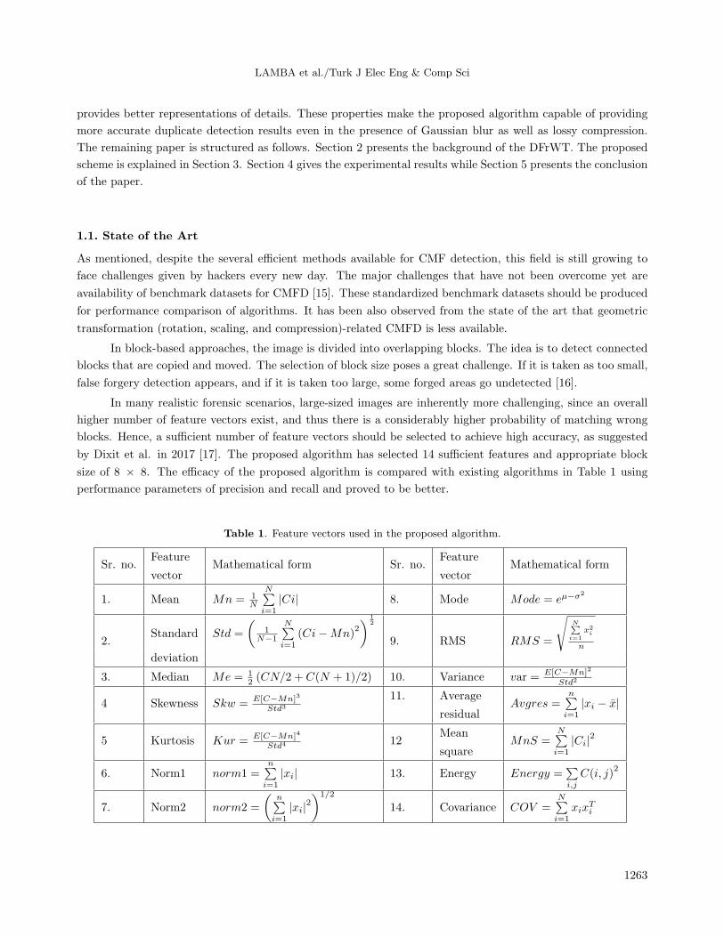
by Dixit et al. in 2017 [17]. The proposed algorithm has selected 14 sufficient features and appropriate block
size of 8 × 8. The efficacy of the proposed algorithm is compared with existing algorithms in Table 1 using
performance parameters of precision and recall and proved to be better.
Table 1. Feature vectors used in the proposed algorithm.
Sr. no.Feature
Mathematical form Sr. no.Feature
Mathematical formvector vector
1. Mean Mn = 1N
N∑i=1
|Ci| 8. Mode Mode = eµ−σ2
2.Standard Std =
(1
N−1
N∑i=1
(Ci−Mn)2
) 12
9. RMS RMS =
√N∑
i=1x2i
n
deviation
3. Median Me = 12 (CN/2 + C(N + 1)/2) 10. Variance var = E[C−Mn]2
Std2
4 Skewness Skw = E[C−Mn]3
Std3
11. AverageAvgres =
n∑i=1
|xi − x|residual
5 Kurtosis Kur = E[C−Mn]4
Std4 12Mean
MnS =N∑i=1
|Ci|2square
6. Norm1 norm1 =n∑
i=1
|xi| 13. Energy Energy =∑i,j
C(i, j)2
7. Norm2 norm2 =
(n∑
i=1
|xi|2)1/2
14. Covariance COV =N∑i=1
xixTi
1263

LAMBA et al./Turk J Elec Eng & Comp Sci
2. Discrete fractional wavelet transform
Fractional wavelet transform is a helpful mathematical transformation that generalizes the prominent tool in
signal processing known as the wavelet transform by rotation of the signals in the time-frequency plane. The
continuous fractional wavelet transform (FrWT) [18] is said to be the actualization of wavelet transform in the
fractional Fourier domain. The FrWT of a one-dimensional g(t) function can be written as:
WTα(s, τ) =
∞∫−∞
∞∫−∞
g(t)Kα(x, t)ϕs, τ(x)dtdx, (1)
where ϕs, τ(x) = 1√sϕ(x−τs
)represents the mother wavelet with parameters s and τ as scale (dilation) and
translation (position), respectively. Further, Kα(x, t) represents the kernel of FrWT as given in Eq. (2).
Kα(x, t) = Cαkα(x, t)e−jtx csc α (2)
Here Cα = e− j
2 (π2
sgn(sin α)−α)√2π|sin α|
. For construction of the actual signal from the transformed signal, inverse FrWT
can be defined as in Eq. (3).
g(t) =1
Cϕ
∞∫−∞
∞∫−∞
∞∫−∞
WTα(s, τ)K−α(x, t)ϕs, τ(x)dsdτdx
s2(3)
Here, Cϕ =∞∫
−∞
|ϕ(u)|2|u| du with ϕ(u) being the Fourier transform of ϕ(t).
Eq. (1) can be rearranged as:
WTα(s, τ) =
∞∫−∞
G(x)ϕs, τ(x)dx, (4)
where G(x) =∞∫
−∞g(t)Kα(x, t)dt .
To get the DFrWT, it is required to give a discrete form of Eq. (4), which further requires the discrete
form of the mother wavelet ϕs, τ(x). To achieve this, scale and translation parameters are considered as s = s0a
and τ = bτ0s0a , respectively. Now the discrete mother wavelet can be described as:
ϕa, b(x) =1√s0a
ϕ
(x− bτ0s0a
s0a
), (5)
where a and b are integers that represent the controlling factors for the scale and position, respectively. s0
is the fixed dilation step with the value being greater than 1, while τ0 is the position parameter with value
greater than zero. The discrete mother wavelet given in Eq. (5) is reduced to get the FrWT of Eq. (4), givenas:
WTαa, b =
∞∫−∞
G(x)1√s0a
ϕ
(x− bτ0s0a
s0a
)dx. (6)
1264

LAMBA et al./Turk J Elec Eng & Comp Sci
The relation in Eq. (6) is the inner product between signal G and wavelet ϕa, b as represented in Eq. (7).
WTαa, b = ⟨G,ϕa, b⟩ (7)
Thus, WTαa, b represents the α -order DFrWT coefficients on a dilation-position grid given by a , b . Usually,
the values of s0 and τ0 are chosen as 2 and 1, respectively, giving the simplest yet effective discrete form, called
a dyadic grid arrangement. The dyadic grid wavelet can be described as:
ϕa, b(x) =1√2a
ϕ
(x− b2a
2a
)⇒ ϕa, b(x) = 2−a/2ϕ(2−ax− b). (8)
Now the forward and the inverse DFrWT are represented in Eqs. (9) and (10), respectively.
WTαa, b =
∞∫−∞
G(x)2−a/2ϕ(2−ax− b)dx ⇒∞∫
−∞
G(x)ϕa, b(x)dx (9)
G(x) =∞∑
a=−∞
∞∑b=−∞
WTαa, bϕa, b(x) ⇒ G(x) =∞∑
a=−∞
∞∑b=−∞
⟨G,ϕa, b⟩ϕa, b(x) (10)
Figure 2 shows the decomposition and reconstruction process for DFrWT for an image.
Original Image
- order DFrFT
l – level DWT
l – level inverse DWT
- order inverse
DFrFT
Reconstructed
Image
l – level -
order DFrWT
Decomposition Reconstruction
Figure 2. Decomposition and reconstruction process for DFrWT.
Thus, we can say that to obtain l -level α -order DFrWT coefficients of an image, α -order discrete fractional
wavelet transform (DFrFT) is followed by l -level discrete wavelet decomposition. However, to obtain the original
image, l -level discrete wavelet reconstruction and then α -order inverse DFrFT are carried out.
3. Proposed scheme
The proposed CMFD scheme relies on the assumption that replicated areas in an image have the same
underlying statistical characteristics, which other areas of the image do not possess. Thus, we have extracted
1265

LAMBA et al./Turk J Elec Eng & Comp Sci
the discriminating attributes from the DFrWT coefficients of different regions of the image for region replication
detection. The proposed scheme can be mainly divided into six steps, namely RGB to grayscale conversion,
overlapping block creation, feature extraction, lexicographical sorting, block matching, and block filtering, as
given in Figure 3.
RGB to Gray-scale Conversion
Overlapping Blocks Creation
Feature Extraction
Lexicographical Sorting
Block Matching
Block Filtering
Test Image
Detection Result
Figure 3. Outline of the proposed CMFD scheme.
3.1. RGB to grayscale conversion
If a test image is an RGB image, it is desired to convert it into a grayscale format. This is done by computing a
weighted average of each color component, namely red (Rc), green (Gc), and blue (Bc).The pixel values of the
corresponding grayscale image are the intensities of the respective pixels of the RGB image. RGB to grayscale
conversion is done by using Eq. (11):
I(Rc,Gc,Bc) = 0.2989 ·Rc+ 0.5870 ·Gc+ 0.1140 ·Bc, (11)
where Rc , Gc , and Bc represent the 8-bit grayscale red, green, and blue intensities, respectively. I(Rc, Gc, Bc)
represents the pixel value in the converted gray-scale image.
3.2. Overlapping block creation
The grayscale image of dimensions u × v is separated into overlapping square blocks with dimensions d × d.
This is done by sliding a square-shaped block of d × dsize over the grayscale image starting from the top-left
1266

LAMBA et al./Turk J Elec Eng & Comp Sci
pixel to the bottom-right pixel. The sliding step is taken as one pixel. This will create a total (u– d+ 1) ×(v– d+ 1) overlapping blocks.
3.3. Feature extraction
The α -order l -level DFrWT is applied to each of the obtained blocks. Therefore, in total (u– d+ 1) × (v–
d+ 1) feature vectors are generated. For each block, we have extracted a total of 14 features from the DFrWT
coefficients. Table 1 gives a list of all these features.
In Table 1, C represents the DFrWT wavelet coefficients; N is the total DFrWT coefficients obtained from
a block, and E [t ] signifies the expected value of the quantity t . In statistics, skewness is the measurement
of statistical data distribution, direction, and degree [19]. It is also a numerical feature of the statistical data
asymmetry degree. Kurtosis, also called the coefficients of kurtosis, indicates the feature number of peak values
for the probability density distribution curve at the average value. Simply speaking, kurtosis reflects the tail
thickness.
3.4. Lexicographical sorting
It is desired to compare all the feature vectors to detect similar ones. However, this process leads to compu-
tational overhead due to the large number of feature vectors. A feasible solution to this problem is to sort the
vectors lexicographically followed by their comparison with their close neighbors. It is presumed that the repli-
cated regions would have similar features, and thus there is a high possibility of having corresponding feature
vectors be very close. Therefore, in our proposed scheme, we have applied lexicographical sorting.
3.5. Block matching
This step involves the matching of feature vectors to find the similar blocks. For this, Euclidean distance (Ed)
is calculated between each possible feature vector pair using Eq. (12).
Ed =
√√√√ n∑i=1
(ai− bi)2 (12)
Here, a and b represent the two feature vectors that are to be compared and n (=14 in our implementation)
is the length of a feature vector. The vectors a and b are assumed to be similar if their corresponding absolute
value of Ed is less than a threshold T . T is the threshold value used in the block matching step of the CMFD
algorithm. Nanda et al. [20] found that it is a great challenge to select the most appropriate threshold value
in the block feature matching in the forgery detection step. The choice of the threshold value also varies with
characteristics of the input stage such as its size.
The proposed algorithm selected threshold values (T ) ranging between 0 and 1, which changes with
image size. The idea to take this range was taken from Lynch et al. [21] for CMFD. It was stated in [22] that
the choice of threshold also depends on the block size, minimum Euclidean distance, and individual feature
parameters.
3.6. Block filtering
The block filtering step plays a significant role in removing false positives, if any, from the matched blocks
obtained from the block matching step. These false positives usually result from the smooth regions present in
1267

LAMBA et al./Turk J Elec Eng & Comp Sci
the test image. For this, a shift vector (Sv) is calculated between two matched blocks using Eq. (13):
Sv = (du, dv) = (ui− uj, vi− vj), (13)
where (ui , vi) and (uj , vj) represent the upper left corner pixels of the matched block pair. Now the
normalization of shift vector Sv is done. If du < 0, then Sv = −Sv ; if du = 0 and dv < 0, then Sv = −Sv .
Then the shift vector length (SL) is calculated. If SL is less than a threshold, NS , then the corresponding
matched block pair is removed. It was also considered in wavelet-based CMF detection in 2012 [23] that a shift
vector whose lengths are less than the threshold will be removed. The value of the threshold will be adapted
for image size. It was suggested in 2014 [24] that in block-based CMFD, the adaptive threshold can be adjusted
proportional to the standard deviation (SD) of the pair block’s intensity.
Based on these two facts, the proposed algorithm also used the SD as a feature vector (see Table 1) and
hence the threshold for each image is calculated from the SD. In the proposed algorithm, the NS range is 20–30
for the CASIA database with differently sized images.
Further, grouping of the rest of the block pairs is done on the basis of their respective shift vector
lengths. A group containing fewer than Ng matched blocks is removed. This is done to remove very small
detected similar regions, which are meaningless.
The output of this step gives the detected replicated regions. A detection map is created to mark all the
similar regions. Figure 4 gives the detailed flowchart of the proposed CMFD scheme.
4. Experimental results and discussion
4.1. Experimental method and procedure
To observe the performance of the proposed algorithm, the Columbia Image Splicing Detection Evaluation
Dataset [25] has been used. It contains the natural grayscale images of dimensions 128 × 128 pixels in the
BMP format. The parameters in the proposed implementation were set as l = 2,NS =24, and Ng= 12. The
100 images from the dataset were tampered with in a random manner and used for training to get the threshold
T .
The performance characteristics used for the examination and analysis of the proposed method are
precision and recall which are determined as in Eqs. (14) and (15), respectively.
precision =FR ∩DR
DR(14)
recall =FR ∩DR
FR(15)
Here, FR is the forged region and DR is the detected region.
4.2. Effect of variation in block size
The effect of changes in the values of block size, d × d , has been studied. For this, the parameters used are
hit rate (Hr) and false alarm rate (Fr). Hr is defined as the ratio of forged images that are detected as forged
with respect to total number of forged images. Fr is defined as the ratio of original images that are detected as
forged to the total number of original images. A total of 100 images were taken from the dataset, which were
1268

LAMBA et al./Turk J Elec Eng & Comp Sci
Test Image
Is S L< NS?
RGB to Gray-scale conversion
Feature Extraction using DFrWT
Lexicographical Sorting
Compute Euclidean distance (Ed) between
each feature vector
Is |Ed| <T?
Compute shift vector length (SL)
Is Image Gray-
Scale?
Group block pairs based on similar shift
vector length
Is no. of blocks in a
group< NS
Detection Result
Ignore these feature vectors
Y
N
N
Y
Y
N
Y
Figure 4. Flowchart of the proposed CMFD scheme.
tampered with in a randomized manner. Figure 5 shows the ROC curve with four block sizes, 4 × 4, 8 × 8,
16 × 16, and 32 × 32, on Hr and Fr.
1269

LAMBA et al./Turk J Elec Eng & Comp Sci
0
0.1
0.2
0.3
0.4
0.5
0.6
0.7
0.8
0.9
1
0 0.1 0.2 0.3 0.4 0.5 0.6 0.7 0.8 0.9 1 H
it R
ate
False Alarm Rate
4 × 4
8 × 8
16 ×16
32 ×32
Figure 5. ROC curve for variation in block size.
The graph clearly indicates that there is a trade-off among the parameters and 16 × 16 block size provides
satisfactory performance. For all the proposed experiments, we thus set d= 16.
4.3. Visual results
To test the efficiency and effectiveness of our technique, we have carried out four types of experiments.
Experiment 1 A random square region was copied from one section and pasted over some other section in the
image. Four images are used for each of the four potential locations in replicated areas: vertical, horizontal,
antidiagonal, and diagonal. Corresponding detection results are presented in Figure 6.
The topmost row shows the original images, the manipulated images are represented in the middle row,
and the result images are shown in the bottom-most row. The proposed technique is evaluated against the
methods in [16,21,26–29] in Table 2. For this, a total of 50 images were used from the dataset to compute
average precision and average recall. The results clearly depict that the proposed system has better detection
accuracy than existing systems.
Table 2. Comparison of proposed and existing CMFD algorithms.
Methods Precision (%) Recall (%)
Huang et al. (2011) [26] 99 99
Singh and Tripathi (2011) [27] 80 75
Lynch et al. (2013) [21] 97 95
Fadl et al. (2014) [28] 99 98
Mangat and Kaur (2016) [29] 95 74
Zhong et al. (2017) [16] 90.1 90.8
Proposed scheme 99 100
State-of-the-art methods used for comparison in Table 2 have the following settings: all the methods
used the block-based approach for CMFD. Performance parameters evaluated by all algorithms are same, i.e.
precision and recall. Most of the methods used the same dataset for CMFD. From the state-of-the-art methods
today in the CMFD field, it is a great challenge to find algorithms with the same approach using the same
benchmark dataset [15] and same performance parameters [17]. Therefore, the authors have tried to select
comparison methods with the proposed one.
1270

LAMBA et al./Turk J Elec Eng & Comp Sci
a
b
c
Figure 6. CMFD results for vertical, horizontal, antidiagonal, and diagonal positions of replicated areas: (a) original
images, (b) manipulated images, (c) detection results.
Experiment 2 A certain section is copied from an image and pasted multiple times over the nonoverlapping
space of the same image. Figure 7 gives the detection results of the proposed system. The first row depicts the
original images, the middle row represents the forged images, and the corresponding detection results of our
algorithm are indicated in the last row.
Experiment 3 We cloned an irregular region and pasted it within the image. This experiment is used to
examine the performance of our method in the case of irregular similar regions. The detection results of this
experiment are shown in Figure 8. The first column indicates original images, the second column shows the
forged images, and the third column represents the detection results by our technique.
Experiment 4 The manipulated images along with the corresponding original images were distorted by Gaus-
sian blurring and lossy compression. For this experiment, 100 original images were forged by copying a certain
1271

LAMBA et al./Turk J Elec Eng & Comp Sci
a
b
c
Figure 7. CMFD results in the case of multiple replicated regions: (a) original images, (b) manipulated images, (c)
detection results.
irregular region and pasting it over some other area in a random manner. Different postprocessing operations
used for distortion are JPEG compression with different quality factors, Qf (Qf = 70, 90), and Gaussian blur-
ring with 3 × 3 window size and standard deviation σ = 1. In Table 3, the average precision for each of the
above mentioned postprocessing operations is depicted. For this experiment, the proposed scheme is compared to
the existing method in [20].
The comparison results indicate that our scheme performs better than the existing method even when
images are maligned with the Gaussian blurring and JPEG compression.
Table 3. Precision for various postprocessing operations.
Methods JPEG (Qf =90) JPEG (Qf =70) Gaussian blurring
Fadl et al. [28] 70% 60% 95%
Proposed scheme 76% 62% 99%
1272

LAMBA et al./Turk J Elec Eng & Comp Sci
a
b
c
Figure 8. CMFD results in the case of irregular replicated region: (a) original images, (b) manipulated images, (c)
detection results.
Experiment 5 The proposed algorithm is also implemented on the CASIA v1. 0 and the CASIA 2 datasets.
The CASIA v1. 0 dataset contains 800 authentic and 921 spliced color images of size 384 × 256 pixels with
JPEG format. Compared to CASIA v1. 0, CASIA v2. 0 is larger in size and has more realistic and challenging
fake images by using postprocessing of tampered regions. It contains 7491 authentic and 5123 tampered color
images. The images in CASIA v2. 0 are different in size, varying from 240 × 160 to 900 × 600 pixels. Figure 9
shows the simulation results of the proposed algorithm. Analysis of the simulation results and Table 4 (accuracy
comparison of the proposed algorithm with the existing) shows that the proposed algorithm gives better results in
comparison with existing methods [30,31].
The execution time to detect the CMF depends on the size of the image as well as the RAM memory of
the system. The proposed algorithm takes 141.23 s (for one image) with MATLAB 2014a on a system having
an Intel Xeon 64-bit processor and 8 GB RAM.
1273

LAMBA et al./Turk J Elec Eng & Comp Sci
Figure 9. CMFD results with CASIA v1. 0 and v2. 0 datasets: (a) original images, (b) manipulated images,
(c) detection results.
Table 4. Accuracy comparison of the proposed method with existing methods.
Methods CASIA v1. 0 CASIA v2. 0
Proposed 99.65 99.01
Rao and Ni [30] 98.04 97.83
Muhammad et al. [31] 94.89 97.33
4.4. Computational complexity
It has been observed from the state-of-the-art methods that wavelet transform-based algorithms for CMFD
reduced the time complexity [32,33]. The proposed algorithm is based on discrete fractional wavelet transform
for CMFD.
Basically, in CMFD, computational complexity depends on selection of the block size (small block size
will increase computational complexity and large block size will decrease the complexity) and the number of
feature vectors. The proposed algorithm has used 16 × 16 block size and 14 feature vectors and its comparison
with existing methods [34–36] is given in Table 5.
5. Conclusion and future work
In this paper, an efficient and effective CMFD algorithm using discrete fractional wavelet transform has been
presented. The proposed technique is capable of detecting similar regions without any prior information about
the images as compared to the prior approaches. The method can successfully detect multiple copies of
duplicated regions. Experimental results demonstrate that our scheme can identify irregular, similar sections
of an image and performs considerably better even under the effects of Gaussian blurring as well as JPEG
compression. Under Gaussian blurring, the proposed method can achieve 99% precision. In case of JPEG
compression with Qf = 70 and 90, 62% and 76% precision have been attained, respectively. However, DFrWT
coefficients do not exhibit the rotational invariance property. Hence, this method has a limitation in that it is
unsuitable for rotational attacks. The performance parameters with 99% precision and 100% recall proved that
1274

LAMBA et al./Turk J Elec Eng & Comp Sci
Table 5. Comparison of computational complexity.
MethodFeature
Block sizeComputation
length complexity
Zernike moments12 24 × 24
Approx. 50 s to
(2010) [34] process one image
Circular block with4 8 × 8 1.5 s to 2.9 min
DCT (2012) [35]
Exemplar-based
- 5 × 5
112 s to 191 s
inpainting method depending on
(2013) [36] image size
Proposed method 14 16 × 16
140 to 0 s
depending on
image size
the proposed algorithm will be very helpful for researchers to detect blind copy-move forgery. In the future, the
efficacy of the proposed algorithm will be checked for other forgery detection techniques like splicing (in which
the forged part belongs to another image).
Acknowledgment
The authors would like to thank the anonymous reviewers for their valuable comments and suggestions to
improve the quality of the paper.
References
[1] Bayram S, Sencar HT, Memon N. A survey of copy-move forgery detection techniques. In: Western Network York
Image Processing Workshop; 2008.
[2] Qazi T, Hayat K, Khan SU, Madani SA, Khan IA, Kolodziej J, Li H, Lin W, Yow KC, Xu CZ. Survey on blind
image forgery detection. IET Image Process 2013; 7: 660-670.
[3] Qureshi MA, Deriche M. A bibliography of pixel-based blind image forgery detection techniques. Signal Process-
Image 2015; 39: 46-74.
[4] Christlein V, Riess C, Jordan J, Riess C, Angelopoulou E . An evaluation of popular copy-move forgery detection
approaches. IEEE T Inf Foren Sec 2012; 7: 1841-1854.
[5] Al-Qershi OM, Khoo BE. Passive detection of copy-move forgery in digital images: state-of-the-art. Forensic Sci
Int 2013; 231: 284-295.
[6] Huang Y, Lu W, Sun W, Long D. Improved DCT-based detection of copy-move forgery in images. Forensic Sci Int
2011; 206: 178-184.
[7] Fridrich J, Soukal D, Lukas J. Detection of copy-move forgery in digital images. In: Digital Forensic Research
Workshop; 2003; Cleveland, OH, USA.
[8] Bhosale S, Thube G, Jangam P, Borse R. Employing SVD and wavelets for digital image forensics and tampering
detection. In: IEEE 2012 International Conference on Advances in Mobile Network, Communication and Its
Applications; 1–2 August 2012; Bangalore, India. New York, NY, USA: IEEE. pp. 135-138.
[9] Popescu AC, Farid H. Exposing Digital Forgeries by Detecting Duplicated Image Regions. Technical Report TR2004-
515. Hanover, NH, USA: Dartmouth College, 2004.
1275

LAMBA et al./Turk J Elec Eng & Comp Sci
[10] Bayram S, Sencar HT, Memon N. An efficient robust method for detecting copy-move forgery. In: IEEE 2009
International Conference on Acoustics, Speech, and Signal Processing; 19–24 April 2009; Taipei, Taiwan. New
York, NY, USA: IEEE. pp. 1053-1056.
[11] Qiao M, Sung A, Liu Q, Ribeiro BM. A novel approach for detection of copy-move forgery. In: IARIA International
Conference on Advanced Engineering Computing and Applications in Sciences; 20–25 November 2011; Lisbon,
Portugal. Wilmington, DE, USA: IARIA. pp. 44-47.
[12] Mahdian B, Saic S. Detection of copy-move forgery using a method based on blur moment invariants. Forensic Sci
Int 2007; 171: 180-189.
[13] Ouyang J, Liu Y, Shu H. Robust hashing for image authentication using SIFT feature and quaternion Zernike
moments. Multimed Tools Appl 2015; 76: 2609-2626.
[14] Liu G, Wang J, Lian S, Wang Z. A passive image authentication scheme for detecting region-duplication forgery
with rotation. J Netw Comput Appl 2011; 34: 1557-1565.
[15] Asghar K, Habib Z, Hussain M. Copy-move and splicing image forgery detection and localization techniques: a
review. Aus J Forensic Sci 2017; 49: 281-307.
[16] Zhong J, Gan Y, Young J, Huang L, Lin P. A new block-based method for copy move forgery detection under image
geometric transforms. Multimed Tools Appl 2017; 76: 14887-14903.
[17] Dixit R, Naskar R. Review, analysis and parameterization of techniques for copy-move forgery detection in digital
images. IET Image Processing 2017; 11: 746-759.
[18] Bhatnagar G, Wu QMJ, Raman B. Discrete fractional wavelet transform and its application to multiple encryption.
Inform Sciences 2013; 223: 297-316.
[19] Gan Y, Zhong J. Image copy-move forgery blind detection algorithm based on the normalized histogram multi-
feature vectors. J Soft Eng 2015; 9: 254-264.
[20] Diane WNN, Xingming S, Moise FK. A survey of partition-based techniques for copy-move forgery detection.
Scientific World J 2014; 2014: 975456.
[21] Lynch G, Shih FY, Liao HYM. An efficient expanding block algorithm for image copy-move forgery detection.
Inform Sciences 2013; 239: 253-265.
[22] Christlein V, Riess C, Jordan J, Riess C, Angelopoulou E. An evaluation of popular copy-move forgery detection
approaches. IEEE T Inf Foren Sec 2012; 7: 1841-1854.
[23] Wang Y, Gurule K, Wise J, Zheng J. Wavelet based region duplication forgery detection. In: IEEE 2012 Ninth
International Conference on Information Technology-New Generations; 16–18 April 2012, Las Vegas, NV, USA.
New York, NY, USA: IEEE. pp. 30-35.
[24] Mohsen Z, Ahmad MA, Mansouri A. Adaptive matching for copy-move forgery detection. In: International Work-
shop on Information Forensics and Security; 2014; Atlanta, GA, USA.
[25] Ng TT. Columbia Image Splicing Detection Evaluation Dataset. New York, NY, USA: Columbia University, 2004.
[26] Huang Y, Lu W, Sun W, Long D. Improved DCT-based detection of copy-move forgery in images. Forensic Sci Int
2011; 206: 178-184.
[27] Singh VK, Tripathi RC. Fast and efficient region duplication detection in digital images using sub-blocking method.
Int J Adv Sci Tech 2011; 35: 93-102.
[28] Fadl SM, Semary NA, Hadhoud MM. Fan search for image copy-move forgery detection. In: Springer 2014
International Conference on Advanced Machine Learning Technologies and Applications; 28–30 November 2014;
Cairo, Egypt. Berlin, Germany: Springer. pp. 177-186.
[29] Mangat SS, Kaur H. A review of literature on copy-move forgery detection techniques. Int J Comput Sci Inf Tech
Secur 2016; 6: 482-486.
[30] Rao Y, Ni J. A deep learning approach to detection of splicing and copy-move forgeries in images. In: International
Workshop on Information Forensics and Security; 2016; Abu Dhabi, UAE.
1276

LAMBA et al./Turk J Elec Eng & Comp Sci
[31] Muhammad G, Al-Hammadi MM, Hussain M, Bebis G. Image forgery detection using steerable pyramid transform
and local binary pattern. Mach Vision Appl 2014; 25: 985-995.
[32] Khan S, Kulkarni A. Reduced time complexity for detection of copy-move forgery using discrete wavelet transform.
Int J Comput Appl 2010; 6: 31-36.
[33] Zhang J, Feng Z, Su Y. A new approach for detecting copy-move forgery in digital images. In: IEEE 2008
International Conference on Communication Systems; 19–21 November 2008; Guangzhou, China. New York, NY,
USA: IEEE. pp. 362-366.
[34] Ryu SJ, Lee MJ, Lee HK. Detection of copy-rotate-move forgery using Zernike moments. In: International Workshop
on Information Hiding; 2010; Berlin, Germany.
[35] Cao Y, Gao T, Fan L, Yang Q. A robust detection algorithm for copy-move forgery in digital images. Forensic Sci
Int 2012; 214: 33-43.
[36] Chang IC, Yu JC, Chang CC. A forgery detection algorithm for exemplar-based inpainting images using multi-region
relation. Image Vision Comput 2013; 31: 57-71.
1277