digital genset controller dgc-500 · section 6 • maintenance and troubleshooting ... the dgc-500...
TRANSCRIPT
INSTRUCTION MANUAL FOR
DIGITAL GENSET CONTROLLER DGC-500
Publication: 9355400990 Revision: G 01/08 www .
Elec
tricalP
artM
anua
ls . c
om
www . El
ectric
alPar
tMan
uals
. com
9355400990 Rev G DGC-500 Introduction i
INTRODUCTION This instruction manual provides information about the operation and installation of the DGC-500 Digital Genset Controller. To accomplish this, the following information is provided:
• General Information and Specifications • Controls and Indicators • Functional Description • Communication Software Description • Installation • Maintenance and Troubleshooting
WARNING! To avoid personal injury or equipment damage, only qualified personnel should perform the procedures in this manual.
NOTE Be sure that the DGC-500 is hard-wired to earth ground with no smaller than 12 AWG copper wire attached to the ground terminal on the rear of the unit case. When the DGC-500 is configured in a system with other devices, it is recommended to use a separate lead to the ground bus from each unit.
www . El
ectric
alPar
tMan
uals
. com
ii DGC-500 Introduction 9355400990 Rev G
First Printing: March 2002
Printed in USA
© 2008 Basler Electric, Highland Illinois 62249 USA
All Rights Reserved
January 2008
It is not the intention of this manual to cover all details and variations in equipment, nor does this manual provide data for every possible contingency regarding installation or operation. The availability and design of all features and options are subject to modification without notice. Should further information be required, contact Basler Electric.
BASLER ELECTRIC ROUTE 143, BOX 269
HIGHLAND IL 62249 USA http://www.basler.com, [email protected]
PHONE +1 618.654.2341 FAX +1 618.654.2351
CONFIDENTIAL INFORMATION of Basler Electric, Highland Illinois, USA. It is loaned for confidential use, subject to return on request, and with the mutual understanding that it will not be used in any manner detrimental to the interest of Basler Electric.
www . El
ectric
alPar
tMan
uals
. com
9355400990 Rev G DGC-500 Introduction iii
REVISION HISTORY
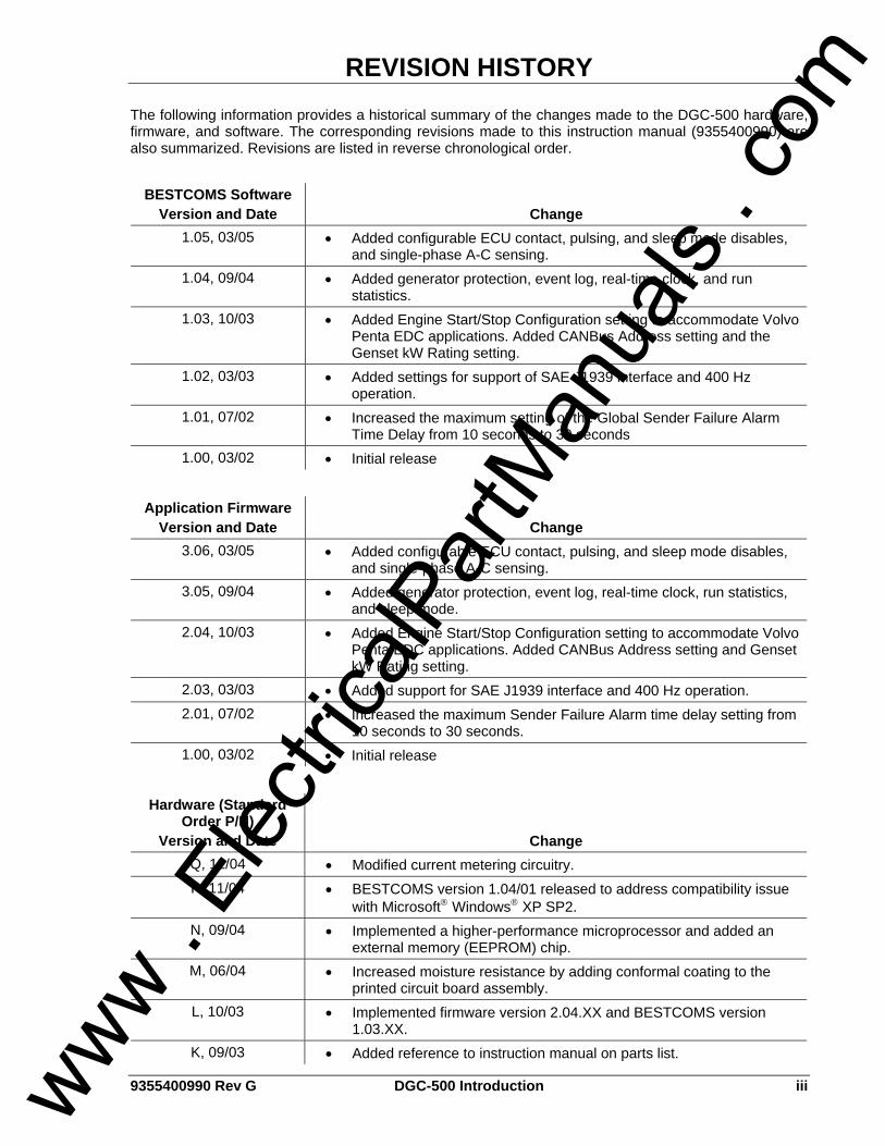
The following information provides a historical summary of the changes made to the DGC-500 hardware, firmware, and software. The corresponding revisions made to this instruction manual (9355400990) are also summarized. Revisions are listed in reverse chronological order.
BESTCOMS Software Version and Date Change
1.05, 03/05 • Added configurable ECU contact, pulsing, and sleep mode disables, and single-phase A-C sensing.
1.04, 09/04 • Added generator protection, event log, real-time clock, and run statistics.
1.03, 10/03 • Added Engine Start/Stop Configuration setting to accommodate Volvo Penta EDC applications. Added CANBus Address setting and the Genset kW Rating setting.
1.02, 03/03 • Added settings for support of SAE J1939 interface and 400 Hz operation.
1.01, 07/02 • Increased the maximum setting of the Global Sender Failure Alarm Time Delay from 10 seconds to 30 seconds
1.00, 03/02 • Initial release
Application Firmware
Version and Date Change 3.06, 03/05 • Added configurable ECU contact, pulsing, and sleep mode disables,
and single-phase A-C sensing. 3.05, 09/04 • Added generator protection, event log, real-time clock, run statistics,
and sleep mode. 2.04, 10/03 • Added Engine Start/Stop Configuration setting to accommodate Volvo
Penta EDC applications. Added CANBus Address setting and Genset kW Rating setting.
2.03, 03/03 • Added support for SAE J1939 interface and 400 Hz operation. 2.01, 07/02 • Increased the maximum Sender Failure Alarm time delay setting from
10 seconds to 30 seconds. 1.00, 03/02 • Initial release
Hardware (Standard
Order P/N) Version and Date Change
Q, 12/04 • Modified current metering circuitry. P, 11/04 • BESTCOMS version 1.04/01 released to address compatibility issue
with Microsoft® Windows® XP SP2. N, 09/04 • Implemented a higher-performance microprocessor and added an
external memory (EEPROM) chip. M, 06/04 • Increased moisture resistance by adding conformal coating to the
printed circuit board assembly. L, 10/03 • Implemented firmware version 2.04.XX and BESTCOMS version
1.03.XX. K, 09/03 • Added reference to instruction manual on parts list.
www . El
ectric
alPar
tMan
uals
. com
iv DGC-500 Introduction 9355400990 Rev G
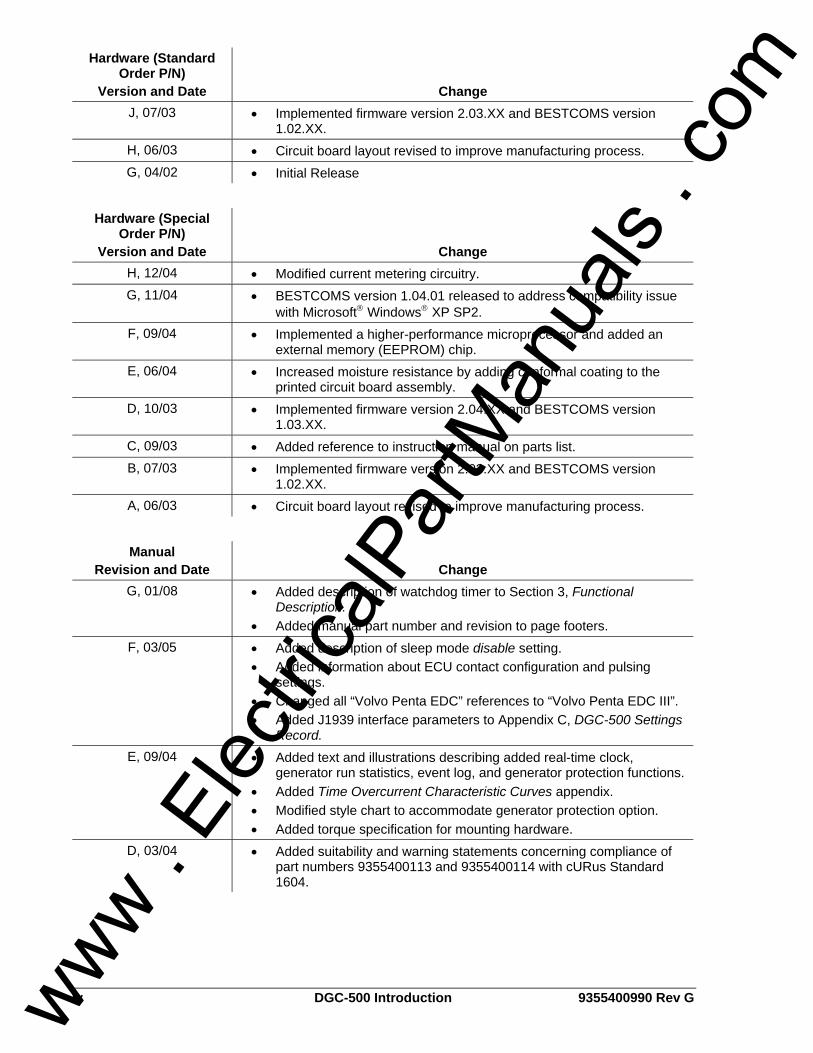
Hardware (Standard Order P/N)
Version and Date Change J, 07/03 • Implemented firmware version 2.03.XX and BESTCOMS version
1.02.XX. H, 06/03 • Circuit board layout revised to improve manufacturing process. G, 04/02 • Initial Release
Hardware (Special
Order P/N) Version and Date Change
H, 12/04 • Modified current metering circuitry. G, 11/04 • BESTCOMS version 1.04.01 released to address compatibility issue
with Microsoft® Windows® XP SP2. F, 09/04 • Implemented a higher-performance microprocessor and added an
external memory (EEPROM) chip. E, 06/04 • Increased moisture resistance by adding conformal coating to the
printed circuit board assembly. D, 10/03 • Implemented firmware version 2.04.XX and BESTCOMS version
1.03.XX. C, 09/03 • Added reference to instruction manual on parts list. B, 07/03 • Implemented firmware version 2.03.XX and BESTCOMS version
1.02.XX. A, 06/03 • Circuit board layout revised to improve manufacturing process.
Manual
Revision and Date Change G, 01/08 • Added description of watchdog timer to Section 3, Functional
Description. • Added manual part number and revision to page footers.
F, 03/05 • Added description of sleep mode disable setting. • Added information about ECU contact configuration and pulsing
settings. • Changed all “Volvo Penta EDC” references to “Volvo Penta EDC III”. • Added J1939 interface parameters to Appendix C, DGC-500 Settings
Record. E, 09/04 • Added text and illustrations describing added real-time clock,
generator run statistics, event log, and generator protection functions. • Added Time Overcurrent Characteristic Curves appendix. • Modified style chart to accommodate generator protection option. • Added torque specification for mounting hardware.
D, 03/04 • Added suitability and warning statements concerning compliance of part numbers 9355400113 and 9355400114 with cURus Standard 1604.
www . El
ectric
alPar
tMan
uals
. com
9355400990 Rev G DGC-500 Introduction v
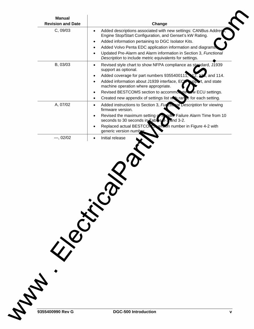
Manual Revision and Date Change
C, 09/03 • Added descriptions associated with new settings: CANBus Address, Engine Stop/Start Configuration, and Genset’s kW Rating.
• Added information pertaining to DGC Isolator Kits. • Added Volvo Penta EDC application information and diagrams. • Updated Pre-Alarm and Alarm information in Section 3, Functional
Description to include metric equivalents for settings. B, 03/03 • Revised style chart to show NFPA compliance as standard, J1939
support as optional. • Added coverage for part numbers 9355400111, 112, 113, and 114. • Added information about J1939 interface, ECU support, and state
machine operation where appropriate. • Revised BESTCOMS section to accommodate new ECU settings. • Created new appendix of settings list with range for each setting.
A, 07/02 • Added instructions to Section 3, Functional Description for viewing firmware version.
• Revised the maximum setting of Sender Failure Alarm Time from 10 seconds to 30 seconds in Tables 3-1 and 3-2.
• Replaced actual BESTCOMS version number in Figure 4-2 with generic version number.
—, 02/02 • Initial release
www . El
ectric
alPar
tMan
uals
. com

vi DGC-500 Introduction 9355400990 Rev G
This page intentionally left blank.
www . El
ectric
alPar
tMan
uals
. com
9355400990 Rev G DGC-500 Introduction vii
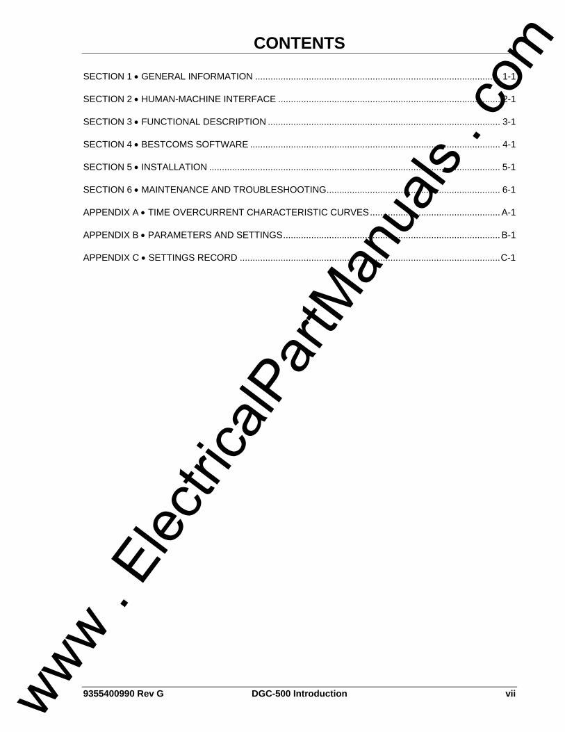
CONTENTS
SECTION 1 • GENERAL INFORMATION ................................................................................................ 1-1
SECTION 2 • HUMAN-MACHINE INTERFACE ....................................................................................... 2-1
SECTION 3 • FUNCTIONAL DESCRIPTION ........................................................................................... 3-1
SECTION 4 • BESTCOMS SOFTWARE .................................................................................................. 4-1
SECTION 5 • INSTALLATION .................................................................................................................. 5-1
SECTION 6 • MAINTENANCE AND TROUBLESHOOTING.................................................................... 6-1
APPENDIX A • TIME OVERCURRENT CHARACTERISTIC CURVES................................................... A-1
APPENDIX B • PARAMETERS AND SETTINGS..................................................................................... B-1
APPENDIX C • SETTINGS RECORD ......................................................................................................C-1
www . El
ectric
alPar
tMan
uals
. com

viii DGC-500 Introduction 9355400990 Rev G
This page intentionally left blank.
www . El
ectric
alPar
tMan
uals
. com
9355400990 Rev G DGC-500 General Information i
SECTION 1 • GENERAL INFORMATION TABLE OF CONTENTS
SECTION 1 • GENERAL INFORMATION ................................................................................................ 1-1
DESCRIPTION....................................................................................................................................... 1-1 FEATURES............................................................................................................................................ 1-1 FUNCTIONS .......................................................................................................................................... 1-1 OUTPUTS.............................................................................................................................................. 1-1 OPTIONAL EQUIPMENT ...................................................................................................................... 1-1 STYLE AND PART NUMBERS ............................................................................................................. 1-2
Style Numbers.................................................................................................................................... 1-2 Part Numbers ..................................................................................................................................... 1-2
SPECIFICATIONS ................................................................................................................................. 1-3 Current Sensing ................................................................................................................................. 1-3 Voltage Sensing ................................................................................................................................. 1-3 Frequency........................................................................................................................................... 1-3 Contact Sensing ................................................................................................................................. 1-3 Engine System Inputs ........................................................................................................................ 1-4 Calculated Data.................................................................................................................................. 1-4 Generator Protection Functions ......................................................................................................... 1-4 Output Contacts ................................................................................................................................. 1-5 Horn Output ........................................................................................................................................ 1-5 Communication Interface ................................................................................................................... 1-5 Environment ....................................................................................................................................... 1-6 Type Tests.......................................................................................................................................... 1-6 UL Recognition................................................................................................................................... 1-6 CSA Certification ................................................................................................................................ 1-6 NFPA Compliance.............................................................................................................................. 1-7 Physical .............................................................................................................................................. 1-7
Figures Figure 1-1. Style Number Identification Chart ........................................................................................... 1-2
Table Table 1-1. Special-Order DGC-500 Controllers ........................................................................................ 1-3
www . El
ectric
alPar
tMan
uals
. com

ii DGC-500 General Information 9355400990 Rev G
This page intentionally left blank.
www . El
ectric
alPar
tMan
uals
. com
9355400990 Rev G DGC-500 General Information 1-1
SECTION 1 • GENERAL INFORMATION DESCRIPTION The DGC-500 Digital Genset Controller provides integrated engine-generator set control, protection, and metering in a single package. Microprocessor based technology allows for exact measurement, setpoint adjustment, and timing functions. Front panel controls and indicators enable quick and simple DGC-500 operation. Basler Electric communication software (BESTCOMS-DGC500-32) allows units to be easily customized for each application. Because of the low sensing burden in the DGC-500, neither dedicated potential transformers (PTs) nor current transformers (CTs) are required. A wide temperature-range liquid crystal display (LCD) with backlighting can be viewed under a wide range of ambient light and temperature conditions. An event log retains a history of system events in nonvolatile memory. Up to 30 event types are retained and each record contains a time stamp and the number of occurrences for each event. Optional, multifunction generator protection guards against generator overvoltage, undervoltage, under-frequency, overfrequency, overcurrent, and phase imbalance. Each generator protection function has an adjustable pickup and time delay setting. Sixteen inverse time curves enable the DGC-500 to offer overcurrent protection in a variety of applications. An optional, SAE J1939 interface provides high-speed communication between the DGC-500 and the engine control unit (ECU) on an electronically controlled engine. This interface provides access to oil pressure, coolant temperature, and engine speed data by reading these parameters directly from the ECU. When available, engine diagnostic data can also be accessed.
FEATURES DGC-500 Digital Genset Controllers have the following features. • Resistant to high moisture, salt fog, humidity, dust, dirt, and chemical contaminants • Resistant to the entrance of insects and rodents • Suitable for mounting in any top mount enclosure • Suitable for controlling isolated generating systems or paralleled generating systems • Serial link communications and BESTCOMS software eases access to setup parameters • Compliant with National Fire Prevention Association (NFPA) Standard 110 • Optional SAE J1939 interface provides high-speed communication with the ECU on electronically
controlled engines
FUNCTIONS DGC-500 Digital Genset Controllers perform the following functions. • Engine cranking control • Generator voltage metering • Generator frequency metering • Generator current metering • Engine coolant temperature metering • Engine coolant temperature protection • Engine oil pressure metering • Engine oil pressure protection • Fuel level sensing • Fuel level sender protection • Fuel leak detector • Engine cool down
• VA metering • Engine rpm metering • Engine run time metering • Battery voltage metering • Battery condition monitoring • Engine maintenance monitoring • Engine diagnostic reporting • Event log stores a history of up to 30 system
event types • Multifunction generator protection (optional)
OUTPUTS Five isolated, form A output contacts are provided: Engine Crank, Fuel Solenoid, Pre-Start, and two user-programmable outputs.
OPTIONAL EQUIPMENT An optional Remote Annunciation Display Panel (RDP-110) is available for use with the DGC-500. www .
Elec
tricalP
artM
anua
ls . c
om
1-2 DGC-500 General Information 9355400990 Rev G
Applications that require remote annunciation can use the Remote Display Panel, RDP-110. This display panel annunciates all DGC-500 alarms, pre-alarms, and operating conditions.
STYLE AND PART NUMBERS Standard-order DGC-500 controllers are identified by a style number. Special-order DGC-500 controllers are specified by ten-digit part numbers
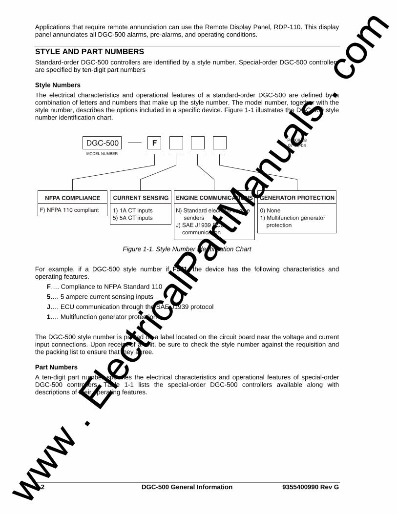
Style Numbers The electrical characteristics and operational features of a standard-order DGC-500 are defined by a combination of letters and numbers that make up the style number. The model number, together with the style number, describes the options included in a specific device. Figure 1-1 illustrates the DGC-500 style number identification chart.
Figure 1-1. Style Number Identification Chart
For example, if a DGC-500 style number if F5J1, the device has the following characteristics and operating features. F…. Compliance to NFPA Standard 110 5…. 5 ampere current sensing inputs J…. ECU communication through the SAE J1939 protocol 1…. Multifunction generator protection The DGC-500 style number is printed on a label located on the circuit board near the voltage and current input connections. Upon receipt of a unit, be sure to check the style number against the requisition and the packing list to ensure that they agree.
Part Numbers A ten-digit part number specifies the electrical characteristics and operational features of special-order DGC-500 controllers. Table 1-1 lists the special-order DGC-500 controllers available along with descriptions of their operating features.
www . El
ectric
alPar
tMan
uals
. com
9355400990 Rev G DGC-500 General Information 1-3
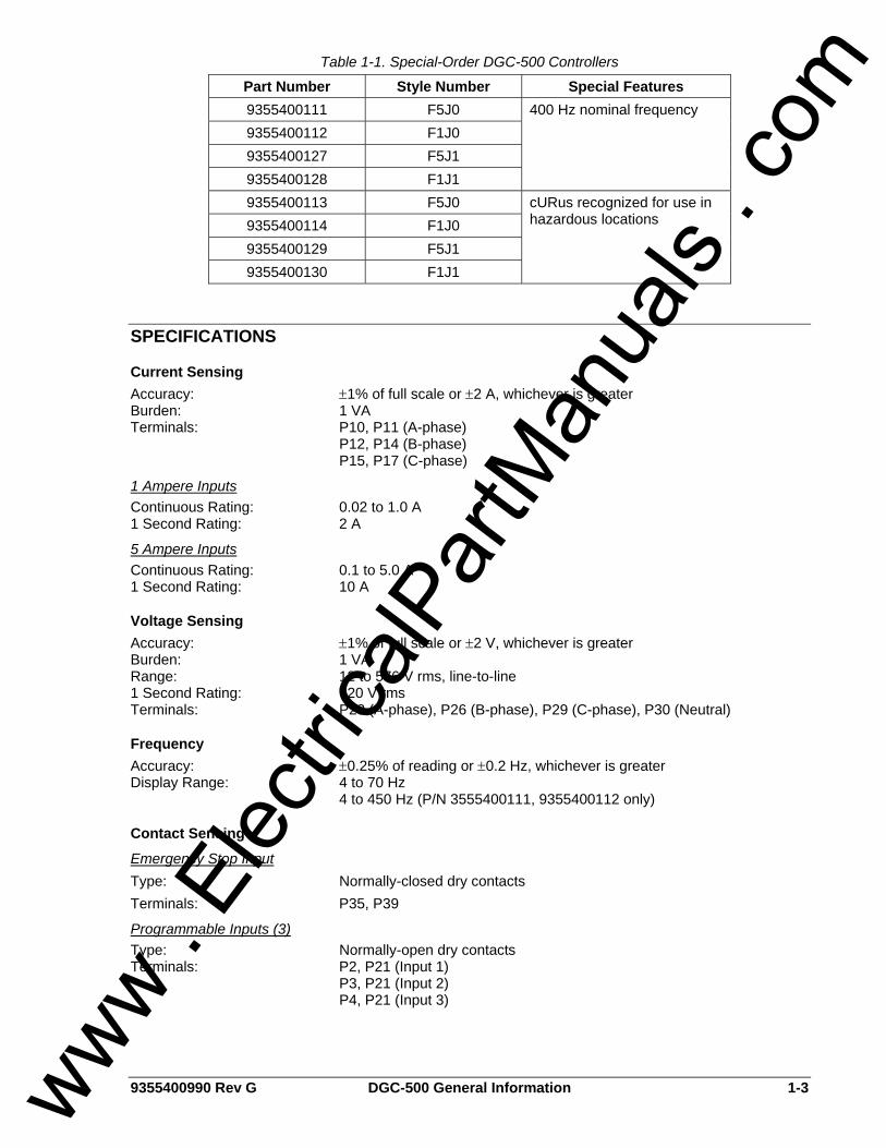
Table 1-1. Special-Order DGC-500 Controllers
Part Number Style Number Special Features 9355400111 F5J0 9355400112 F1J0 9355400127 F5J1 9355400128 F1J1
400 Hz nominal frequency
9355400113 F5J0 9355400114 F1J0 9355400129 F5J1 9355400130 F1J1
cURus recognized for use in hazardous locations
SPECIFICATIONS
Current Sensing Accuracy: ±1% of full scale or ±2 A, whichever is greater Burden: 1 VA Terminals: P10, P11 (A-phase) P12, P14 (B-phase) P15, P17 (C-phase)
1 Ampere Inputs Continuous Rating: 0.02 to 1.0 A 1 Second Rating: 2 A
5 Ampere Inputs Continuous Rating: 0.1 to 5.0 A 1 Second Rating: 10 A
Voltage Sensing Accuracy: ±1% of full scale or ±2 V, whichever is greater Burden: 1 VA Range: 12 to 576 V rms, line-to-line 1 Second Rating: 720 V rms Terminals: P23 (A-phase), P26 (B-phase), P29 (C-phase), P30 (Neutral)
Frequency Accuracy: ±0.25% of reading or ±0.2 Hz, whichever is greater Display Range: 4 to 70 Hz 4 to 450 Hz (P/N 3555400111, 9355400112 only)
Contact Sensing
Emergency Stop Input Type: Normally-closed dry contacts Terminals: P35, P39
Programmable Inputs (3) Type: Normally-open dry contacts Terminals: P2, P21 (Input 1) P3, P21 (Input 2) P4, P21 (Input 3)
www . El
ectric
alPar
tMan
uals
. com
1-4 DGC-500 General Information 9355400990 Rev G
Engine System Inputs ∗ Stated accuracies are subject to the accuracy of the senders used.
Fuel Level Sensing Accuracy: ±3% of indication or ±2% ∗ Range: 33 to 240 Ω nominal Terminals: P16, P19 (common)
Coolant Temperature Sensing Accuracy: ±3% of indication (37°C to 115°C (99°F to 239°F)) ±2°, whichever is greater at 25°C (77°F) ∗ Range: 62.6 to 637.5 Ω nominal Terminals: P18, P19 (common)
Oil Pressure Sensing Accuracy: ±3% of indication (0 to 690 kPa) or ±12 kPa, whichever is greater at
25°C (77°F) Range: 34 to 240 Ω nominal Terminals: P13, P19 (common)
Battery Voltage Sensing Accuracy: ±3% of indication or ±0.2 V, whichever is greater Nominal: 12 or 24 Vdc Range: 8 to 32 Vdc (battery dip ride-through to 6 Vdc for 0.75 sec) Burden: 16 W maximum Terminals: P20 (+), P21 (–)
Magnetic Pickup Sensing Voltage Range: 3 V to 35 V peak continuous into 13 kΩ (during cranking) Frequency Range: 32 to 10,000 Hz Terminals: P39 (+), P40 (–)
Engine RPM Sensing Accuracy: ±0.5% of indication or ±2 rpm, whichever is greater at 25°C (77°F) Range: 750 to 3,600 rpm
Calculated Data
Voltamperes Accuracy: ±2% indication or ±2 kVA, whichever is greater Range: 0 to 9,999 kVA
Engine Run Time Accuracy: ±0.5% of reading or ±1 hour, whichever is greater at 25°C (77°F) Range: 0 to 99,999 hours
Maintenance Interval Accuracy: ±0.5% of reading or ±1 hr, whichever is greater at 25°C (77°F) Range: 0 to 5,000 hours
Generator Protection Functions
Overvoltage (59) and Undervoltage (27) Pickup Range: 70 to 576 Vac Pickup Increment: 1 Vac Inhibit Frequency Range: 20 to 400 Hz (applies to 27 function only) Time Delay Range: 0 to 30 s Time Delay Increment: 0.1 s
www . El
ectric
alPar
tMan
uals
. com
9355400990 Rev G DGC-500 General Information 1-5
Underfrequency (81U) and Overfrequency (81O) Pickup Range: 45 to 65 Hz (50/60 Hz nominal) 360 to 440 Hz (400 Hz nominal) Pickup Increment: 0.1 Hz Inhibit Voltage Range: 70 to 576 Vac (applies to 81U function only) Time Delay Range: 0 to 30 s Time Delay Increment: 0.1 s
Overcurrent (51) Pickup Range: 0.18 to 1.18 Aac (1 A current sensing) 0.9 to 7.75 Aac (5 A current sensing) Time Dial Range: 0 to 30 s (fixed time delay) 0 to 9.9 (inverse curve time multiplier) Time Dial Increment: 0.1 s Inverse Time Curves: See Appendix A, Time Overcurrent Characteristic Curves
Phase Imbalance (47) Pickup Range: 5 to 100 Vac Pickup Increment: 1 Vac Time Delay Range: 0 to 30 s Time Delay Increment: 0.1 s
Output Contacts
Engine Crank, Fuel Solenoid, and Pre-Start Relays Rating: 30 A at 28 Vdc, make, break, and carry ∗ Terminals: K1-N.O., COM (Engine Crank) K2-N.O., COM (Fuel Solenoid) K5-N.O., COM (Pre-Start) ∗ The contact rating is reduced to 3 A for part numbers 9355400113 and 9355400114 when used in a hazardous location.
Programmable Relays (2) Rating: 2 A at 30 Vdc, make, break, and carry Terminals: P33, P34 (Output 1) P36, P38 (Output 2)
Horn Output Voltage: 24 Vdc or battery voltage, whichever is less Current: 15 mAdc maximum Compatible Device: Basler P/N 29760 Terminals: P24 (+), P25 (–)
Communication Interface
Full Duplex RS-232 Connection: Female DB-9 connector (J1) Baud: 1200, 2400, or 9600 Data Bits: 8 Parity: None, Odd, or Even Stop Bit: 1
SAE J1939 Interface Differential Bus Voltage: 1.5 to 3 Vdc Maximum Voltage: –32 to 32 Vdc (with respect to negative battery terminal) Communication Rate: 250 kb/s
www . El
ectric
alPar
tMan
uals
. com
1-6 DGC-500 General Information 9355400990 Rev G
Environment
Temperature Range Operating: –20 to 60°C (–4 to 140°F) Storage: –40 to 85°C (–40 to 185°F)
Type Tests
Shock 15 G in 3 perpendicular planes
Vibration Swept over the following ranges for 12 sweeps in each of three mutually perpendicular planes with each 15 minute sweep consisting of the following: 5 to 29 to 5 Hz: 1.5 G peak for 5 min. 29 to 52 to 29 Hz: 0.036” DECS-A for 2.5 min. 52 to 500 to 52 Hz: 5 G peak for 7.5 min.
Salt Fog Tested per ASTM-117B-1989
Radio Interference Type tested using a 5 W, hand-held transceiver operating at random frequencies centered around 144 and 440 MHz with the antenna located within 150 mm (6”) of the device in both vertical and horizontal planes.
Dielectric Strength 2,352 Vac at 50/60 Hz for 1 second between voltage sensing inputs and all other circuits. 500 Vac at 50/60 Hz for 1 minute between any of the following groups. Current Sensing Inputs: 8 mA RS-232 Port: 6 mA
UL Recognition All DGC-500 controllers are UL recognized per Standard 508, Standard for Industrial Control Equipment (UL File E97035).
Part Numbers 9355400113 and 9355400114 cURus recognized per Standard 1604, Electrical Equipment for Use in Class I and II, Division 2, and Class III Hazardous (Classified) Locations, Class I, Division 2, Groups A, B, C, D, Zone 2, Temperature Code T5. This equipment is suitable for use in Class I, Division 2, Groups A, B, C, D, or nonhazardous locations only.
CSA Certification Certified per Standard CAN/CSA-C22.2, Number 14-95, CSA File LR 23131 (excludes P/N 9355400113 and 9355400114).
WARNING! - EXPLOSION HAZARD (9355400113 and 9355400114 only)
Substitution of components may impair suitability for Class I, Division 2. Do not disconnect equipment unless power has been switched off or the area is known to be non-hazardous.
www . El
ectric
alPar
tMan
uals
. com
9355400990 Rev G DGC-500 General Information 1-7
NFPA Compliance All DGC-500 controllers comply with NFPA Standard 110, Standard for Emergency and Standby Power Systems.
Physical Weight: 680 g (1.5 lb)
www . El
ectric
alPar
tMan
uals
. com

1-8 DGC-500 General Information 9355400990 Rev G
This page intentionally left blank.
www . El
ectric
alPar
tMan
uals
. com
9355400990 Rev G DGC-500 Human-Machine Interface i
SECTION 2 • HUMAN-MACHINE INTERFACE TABLE OF CONTENTS
SECTION 2 • HUMAN-MACHINE INTERFACE ....................................................................................... 2-1
INTRODUCTION.................................................................................................................................... 2-1 FRONT PANEL...................................................................................................................................... 2-1 REAR PANEL ........................................................................................................................................ 2-2
Figures Figure 2-1. Front Panel HMI ...................................................................................................................... 2-1 Figure 2-2. Rear Panel HMI....................................................................................................................... 2-3
Tables Table 2-1. Front Panel HMI Descriptions .................................................................................................. 2-2 Table 2-2. Rear Panel HMI Descriptions................................................................................................... 2-4
www . El
ectric
alPar
tMan
uals
. com

ii DGC-500 Human-Machine Interface 9355400990 Rev G
This page intentionally left blank.
www . El
ectric
alPar
tMan
uals
. com
9355400990 Rev G DGC-500 Human-Machine Interface 2-1
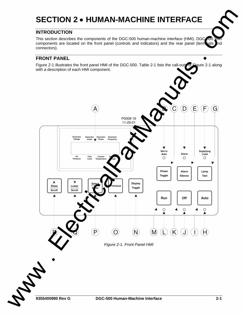
SECTION 2 • HUMAN-MACHINE INTERFACE INTRODUCTION This section describes the components of the DGC-500 human-machine interface (HMI). DGC-500 HMI components are located on the front panel (controls and indicators) and the rear panel (terminals and connectors).
FRONT PANEL Figure 2-1 illustrates the front panel HMI of the DGC-500. Table 2-1 lists the call-outs of Figure 2-1 along with a description of each HMI component.
Figure 2-1. Front Panel HMI
www . El
ectric
alPar
tMan
uals
. com
2-2 DGC-500 Human-Machine Interface 9355400990 Rev G
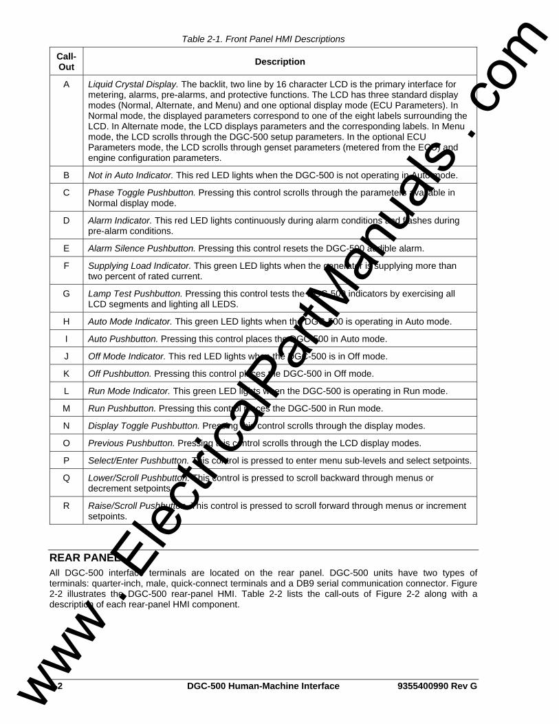
Table 2-1. Front Panel HMI Descriptions
Call-Out Description
A Liquid Crystal Display. The backlit, two line by 16 character LCD is the primary interface for metering, alarms, pre-alarms, and protective functions. The LCD has three standard display modes (Normal, Alternate, and Menu) and one optional display mode (ECU Parameters). In Normal mode, the displayed parameters correspond to one of the eight labels surrounding the LCD. In Alternate mode, the LCD displays parameters and the corresponding labels. In Menu mode, the LCD scrolls through the DGC-500 setup parameters. In the optional ECU Parameters mode, the LCD scrolls through genset parameters (metered from the ECU) and engine configuration parameters.
B Not in Auto Indicator. This red LED lights when the DGC-500 is not operating in Auto mode.
C Phase Toggle Pushbutton. Pressing this control scrolls through the parameters available in Normal display mode.
D Alarm Indicator. This red LED lights continuously during alarm conditions and flashes during pre-alarm conditions.
E Alarm Silence Pushbutton. Pressing this control resets the DGC-500 audible alarm.
F Supplying Load Indicator. This green LED lights when the generator is supplying more than two percent of rated current.
G Lamp Test Pushbutton. Pressing this control tests the DGC-500 indicators by exercising all LCD segments and lighting all LEDS.
H Auto Mode Indicator. This green LED lights when the DGC-500 is operating in Auto mode.
I Auto Pushbutton. Pressing this control places the DGC-500 in Auto mode.
J Off Mode Indicator. This red LED lights when the DGC-500 is in Off mode.
K Off Pushbutton. Pressing this control places the DGC-500 in Off mode.
L Run Mode Indicator. This green LED lights when the DGC-500 is operating in Run mode.
M Run Pushbutton. Pressing this control places the DGC-500 in Run mode.
N Display Toggle Pushbutton. Pressing this control scrolls through the display modes.
O Previous Pushbutton. Pressing this control scrolls through the LCD display modes.
P Select/Enter Pushbutton. This control is pressed to enter menu sub-levels and select setpoints.
Q Lower/Scroll Pushbutton. This control is pressed to scroll backward through menus or decrement setpoints.
R Raise/Scroll Pushbutton. This control is pressed to scroll forward through menus or increment setpoints.
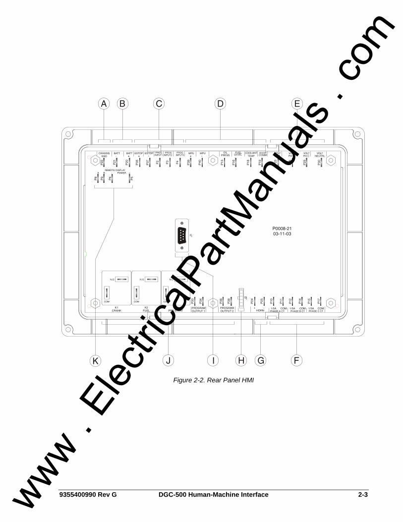
REAR PANEL All DGC-500 interface terminals are located on the rear panel. DGC-500 units have two types of terminals: quarter-inch, male, quick-connect terminals and a DB9 serial communication connector. Figure 2-2 illustrates the DGC-500 rear-panel HMI. Table 2-2 lists the call-outs of Figure 2-2 along with a description of each rear-panel HMI component.
www . El
ectric
alPar
tMan
uals
. com
9355400990 Rev G DGC-500 Human-Machine Interface 2-3
Figure 2-2. Rear Panel HMI
www . El
ectric
alPar
tMan
uals
. com
2-4 DGC-500 Human-Machine Interface 9355400990 Rev G
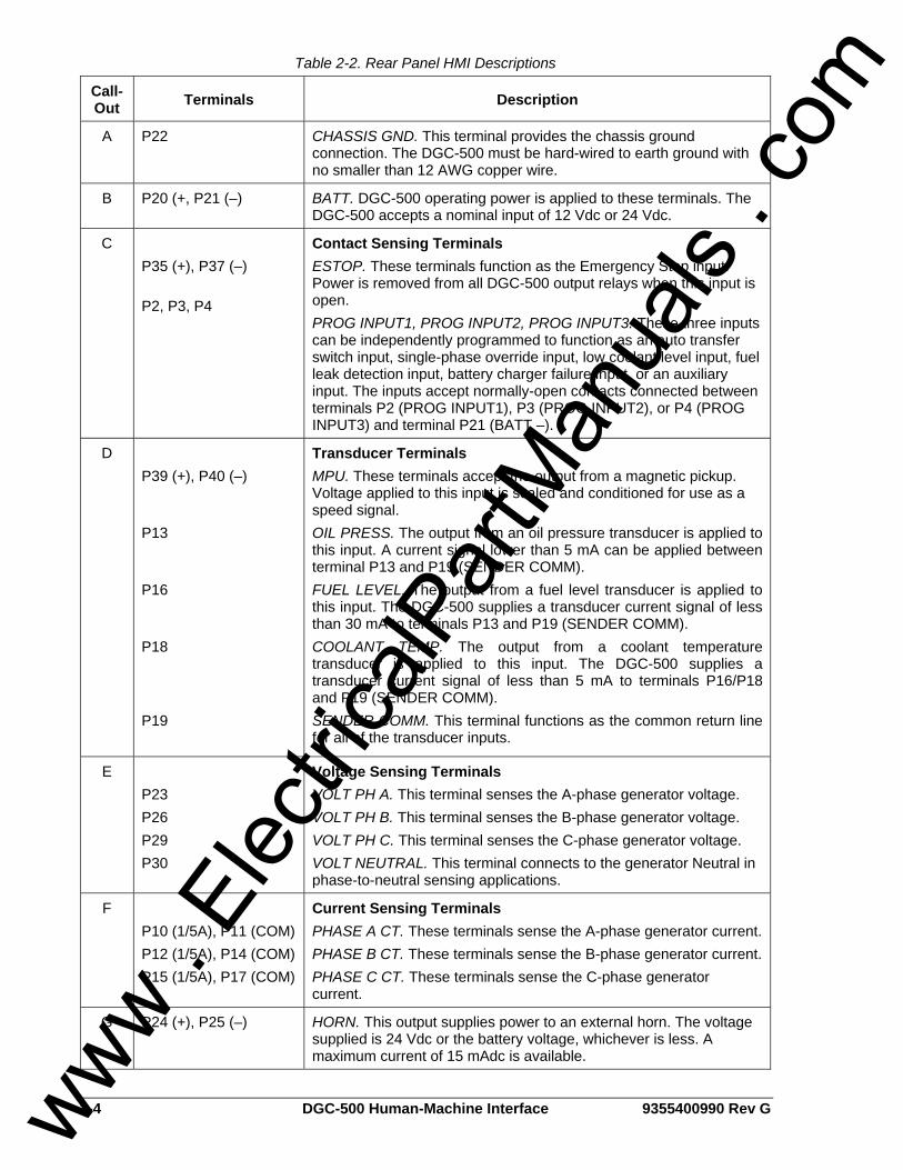
Table 2-2. Rear Panel HMI Descriptions
Call-Out Terminals Description
A P22 CHASSIS GND. This terminal provides the chassis ground connection. The DGC-500 must be hard-wired to earth ground with no smaller than 12 AWG copper wire.
B P20 (+, P21 (–) BATT. DGC-500 operating power is applied to these terminals. The DGC-500 accepts a nominal input of 12 Vdc or 24 Vdc.
C P35 (+), P37 (–) P2, P3, P4
Contact Sensing Terminals ESTOP. These terminals function as the Emergency Stop input. Power is removed from all DGC-500 output relays when this input is open. PROG INPUT1, PROG INPUT2, PROG INPUT3. These three inputs can be independently programmed to function as an auto transfer switch input, single-phase override input, low coolant level input, fuel leak detection input, battery charger failure input, or an auxiliary input. The inputs accept normally-open contacts connected between terminals P2 (PROG INPUT1), P3 (PROG INPUT2), or P4 (PROG INPUT3) and terminal P21 (BATT –).
D P39 (+), P40 (–) P13 P16 P18 P19
Transducer Terminals MPU. These terminals accept the output from a magnetic pickup. Voltage applied to this input is scaled and conditioned for use as a speed signal. OIL PRESS. The output from an oil pressure transducer is applied to this input. A current signal lower than 5 mA can be applied between terminal P13 and P19 (SENDER COMM). FUEL LEVEL. The output from a fuel level transducer is applied to this input. The DGC-500 supplies a transducer current signal of less than 30 mA to terminals P13 and P19 (SENDER COMM). COOLANT TEMP. The output from a coolant temperature transducer is applied to this input. The DGC-500 supplies a transducer current signal of less than 5 mA to terminals P16/P18 and P19 (SENDER COMM). SENDER COMM. This terminal functions as the common return line for all of the transducer inputs.
E P23 P26 P29 P30
Voltage Sensing Terminals VOLT PH A. This terminal senses the A-phase generator voltage. VOLT PH B. This terminal senses the B-phase generator voltage. VOLT PH C. This terminal senses the C-phase generator voltage. VOLT NEUTRAL. This terminal connects to the generator Neutral in phase-to-neutral sensing applications.
F P10 (1/5A), P11 (COM) P12 (1/5A), P14 (COM) P15 (1/5A), P17 (COM)
Current Sensing Terminals PHASE A CT. These terminals sense the A-phase generator current. PHASE B CT. These terminals sense the B-phase generator current. PHASE C CT. These terminals sense the C-phase generator current.
G P24 (+), P25 (–) HORN. This output supplies power to an external horn. The voltage supplied is 24 Vdc or the battery voltage, whichever is less. A maximum current of 15 mAdc is available.
www . El
ectric
alPar
tMan
uals
. com
9355400990 Rev G DGC-500 Human-Machine Interface 2-5
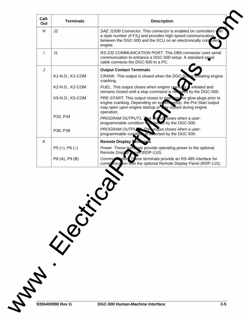
Call-Out Terminals Description
H J2 SAE J1939 Connector. This connector is enabled on controllers with a style number of FXJ and provides high-speed communication between the DGC-500 and the ECU on an electronically controlled engine.
I J1 RS-232 COMMUNICATION PORT. This DB9 connector uses serial communication to enhance a DGC-500 setup. A standard serial cable connects the DGC-500 to a PC.
J K1-N.O., K1-COM K2-N.O., K2-COM K5-N.O., K5-COM P33, P34 P36, P38
Output Contact Terminals CRANK. This output is closed when the DGC-500 is initiating engine cranking. FUEL. This output closes when engine cranking is initiated and remains closed until a stop command is received by the DGC-500. PRE-START. This output closes to energize the glow plugs prior to engine cranking. Depending on system setup, the Pre-Start output may open upon engine startup or stay closed during engine operation. PROGRAM OUTPUT1. This output closes when a user-programmable condition is detected by the DGC-500. PROGRAM OUTPUT2. This output closes when a user-programmable condition is detected by the DGC-500.
K P5 (+), P6 (–) P8 (A), P9 (B)
Remote Display Terminals Power. These terminals provide operating power to the optional Remote Display Panel (RDP-110). Communication. These terminals provide an RS-485 interface for communication with the optional Remote Display Panel (RDP-110).
www . El
ectric
alPar
tMan
uals
. com
2-6 DGC-500 Human-Machine Interface 9355400990 Rev G
This page intentionally left blank.
www . El
ectric
alPar
tMan
uals
. com
9355400990 Rev G DGC-500 Functional Description i
SECTION 3 • FUNCTIONAL DESCRIPTION TABLE OF CONTENTS
SECTION 3 • FUNCTIONAL DESCRIPTION ........................................................................................... 3-1
INTRODUCTION.................................................................................................................................... 3-1 DGC-500 FUNCTION BLOCKS............................................................................................................. 3-1
Power Supply ..................................................................................................................................... 3-1 Microprocessor................................................................................................................................... 3-1 Voltage Sensing Inputs ...................................................................................................................... 3-2 Current Sensing Inputs....................................................................................................................... 3-2 Transducer Inputs .............................................................................................................................. 3-2 Speed Signal Inputs ........................................................................................................................... 3-3 Contact Input Circuitry........................................................................................................................ 3-3 Front Panel HMI ................................................................................................................................. 3-3 Remote Display Panel........................................................................................................................ 3-4 RS-232 Communication Port.............................................................................................................. 3-4 SAE J1939 Interface (Optional).......................................................................................................... 3-4 Horn Output ........................................................................................................................................ 3-7 Output Contacts ................................................................................................................................. 3-7
SOFTWARE OPERATION .................................................................................................................... 3-8 Power-Up Sequence .......................................................................................................................... 3-8 Cranking ............................................................................................................................................. 3-8 Pre-Alarms.......................................................................................................................................... 3-9 Alarms .............................................................................................................................................. 3-10 Real-Time Clock............................................................................................................................... 3-11 Generator Run Statistics .................................................................................................................. 3-11 Event Log ......................................................................................................................................... 3-12 Generator Protection ........................................................................................................................ 3-12
DISPLAY OPERATION........................................................................................................................ 3-14 Normal Mode.................................................................................................................................... 3-14 Alternate Mode ................................................................................................................................. 3-14 ECU Parameters Mode .................................................................................................................... 3-16 Menu Mode....................................................................................................................................... 3-19 Sleep Mode ...................................................................................................................................... 3-20 Changing Settings ............................................................................................................................ 3-25 Setting the Real-Time Clock at the Front Panel............................................................................... 3-25 Key Code.......................................................................................................................................... 3-25 Front Panel Adjustable Parameters ................................................................................................. 3-26
ENGINE CONTROL UNIT (ECU) SUPPORT...................................................................................... 3-26 Enabling ECU Support ..................................................................................................................... 3-26 ECU Constraints............................................................................................................................... 3-26 Alarms and Pre-Alarms .................................................................................................................... 3-27 Fuel Solenoid Relay ......................................................................................................................... 3-27 Display Values (ECU Support Enabled)........................................................................................... 3-27 ECUs with an External Fuel Solenoid .............................................................................................. 3-28
STATE MACHINES ............................................................................................................................. 3-28 System Configuration ....................................................................................................................... 3-28 Operating States .............................................................................................................................. 3-28 State Transitions .............................................................................................................................. 3-29 Normal Program Control .................................................................................................................. 3-29 ECU Power Support Program Control ............................................................................................. 3-29 Initial State - Power Up/Reset .......................................................................................................... 3-30 Ready State...................................................................................................................................... 3-31 Pulsing State .................................................................................................................................... 3-32 Connecting State.............................................................................................................................. 3-32 Pre-Start State.................................................................................................................................. 3-32 Cranking State.................................................................................................................................. 3-33 Resting State.................................................................................................................................... 3-33
www . El
ectric
alPar
tMan
uals
. com
ii DGC-500 Functional Description 9355400990 Rev G
Running State................................................................................................................................... 3-34 Cooling State .................................................................................................................................... 3-34 Shutting Down State......................................................................................................................... 3-35 Alarm State....................................................................................................................................... 3-35
Figures Figure 3-1. Function Block Diagram.......................................................................................................... 3-1 Figure 3-2. Display Mode Navigation ...................................................................................................... 3-14 Figure 3-3. Alternate Mode Navigation.................................................................................................... 3-15 Figure 3-4. Lamp Status Screen.............................................................................................................. 3-15 Figure 3-5. DTC Screen Example ........................................................................................................... 3-16 Figure 3-6. ECU Parameters Navigation................................................................................................. 3-18 Figure 3-7. Engine Configuration Menu Navigation ................................................................................ 3-19 Figure 3-8. Menu Mode Navigation ......................................................................................................... 3-19 Figure 3-9. Menu 1 Navigation ................................................................................................................ 3-21 Figure 3-10. Menu 2 Navigation .............................................................................................................. 3-22 Figure 3-11. Menu 3 Navigation .............................................................................................................. 3-23 Figure 3-12. Menu 4 Navigation .............................................................................................................. 3-24 Figure 3-13. Menu 5 Navigation .............................................................................................................. 3-24 Figure 3-14. Setting Change Example .................................................................................................... 3-25 Figure 3-15. Screens Shown Following Unsuccessful Information Update from ECU ........................... 3-28 Figure 3-16. Normal Program Control Diagram ...................................................................................... 3-29 Figure 3-17. ECU Power Support Program Control Diagram ................................................................. 3-30 Figure 3-18. Power Up/Reset State Diagram.......................................................................................... 3-31 Figure 3-19. Ready State Diagram.......................................................................................................... 3-31 Figure 3-20. Pulsing State Diagram ........................................................................................................ 3-32 Figure 3-21. Connecting State Diagram.................................................................................................. 3-32 Figure 3-22. Pre-Start State Diagram...................................................................................................... 3-33 Figure 3-23. Cranking State Diagram...................................................................................................... 3-33 Figure 3-24. Resting State Diagram........................................................................................................ 3-34 Figure 3-25. Running State Diagram....................................................................................................... 3-34 Figure 3-26. Cooling State Diagram........................................................................................................ 3-35 Figure 3-27. Shutting Down State Diagram............................................................................................. 3-35 Figure 3-28. Alarm State Diagram........................................................................................................... 3-36
Tables Table 3-1. ECU Parameters Obtained from CAN Interface....................................................................... 3-5 Table 3-2. Engine Configuration Parameters Obtained from CAN Interface ............................................ 3-6 Table 3-3. Diagnostic Information Obtained Over the CAN Interface ....................................................... 3-7 Table 3-4. Front Panel Adjustable Settings............................................................................................. 3-26
www . El
ectric
alPar
tMan
uals
. com
9355400990 Rev G DGC-500 Functional Description 3-1
SECTION 3 • FUNCTIONAL DESCRIPTION INTRODUCTION This section describes how the DGC-500 functions and explains its operating features. A detailed description of each function block is provided in the paragraphs under the heading of DGC-500 Function Blocks. DGC-500 operating features are described under the heading of Software Operation.
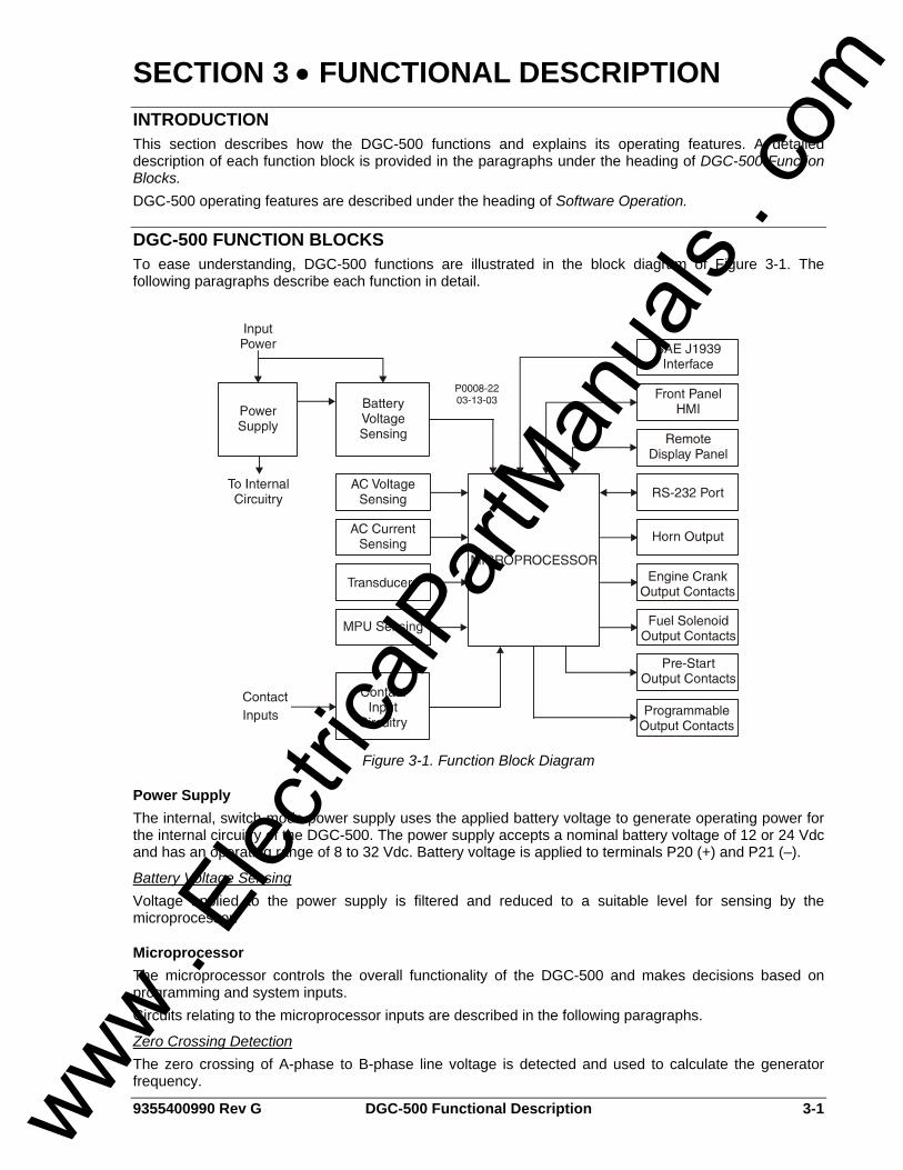
DGC-500 FUNCTION BLOCKS To ease understanding, DGC-500 functions are illustrated in the block diagram of Figure 3-1. The following paragraphs describe each function in detail.
Figure 3-1. Function Block Diagram
Power Supply The internal, switch-mode power supply uses the applied battery voltage to generate operating power for the internal circuitry of the DGC-500. The power supply accepts a nominal battery voltage of 12 or 24 Vdc and has an operating range of 8 to 32 Vdc. Battery voltage is applied to terminals P20 (+) and P21 (–).
Battery Voltage Sensing Voltage applied to the power supply is filtered and reduced to a suitable level for sensing by the microprocessor.
Microprocessor The microprocessor controls the overall functionality of the DGC-500 and makes decisions based on programming and system inputs. Circuits relating to the microprocessor inputs are described in the following paragraphs.
Zero Crossing Detection The zero crossing of A-phase to B-phase line voltage is detected and used to calculate the generator frequency.
www . El
ectric
alPar
tMan
uals
. com
3-2 DGC-500 Functional Description 9355400990 Rev G
Analog-to-Digital Converter Scaled and conditioned signals representing the sensing voltage, sensing current, coolant temperature, fuel level, oil pressure, and battery voltage are digitized by the microprocessor’s 10-bit analog-to-digital converter. The digitized information is stored in random access memory (RAM) and used by the microprocessor for all metering and protection functions.
Watchdog Timer The watchdog timer monitors the firmware executed by the microprocessor. If the firmware ceases normal operation, the watchdog timer will reset the microprocessor. After reset, the microprocessor will resume normal operation if the condition that caused the watchdog reset is no longer present. If the condition is still present, the unit will reset repeatedly until normal operation is resumed or until the watchdog count reaches five. If the count reaches five, the unit will go to watchdog lockout mode. If a half-hour elapses after the most recent reset and the watchdog count has not reached five, the watchdog count is cleared. Once the unit enters the watchdog lockout mode, a power cycle is required to clear the lockout.
Voltage Sensing Inputs Generator voltages applied to the voltage sensing inputs are scaled to levels suitable for use by the internal circuitry. Voltage sensing configuration is menu-selectable. The voltage sensing inputs accept a maximum voltage of 576 Vrms, line-to-line. Sensing voltage is applied to terminals P23 (A-phase), P26 (B-phase), P29 (C-phase), and P30 (Neutral).
Current Sensing Inputs Generator currents are sensed and scaled to values suitable for use by the internal circuitry. Isolation is provided by internal current transformers (CTs). DGC-500–X1 units accept a maximum current value of 1 Aac. DGC-500–X5 units accept a maximum current value of 5 Aac. Sensing current is applied to terminals P10 and P11 (A-phase), P12 and P14 (B-phase), and P15 and P17 (C-phase).
Transducer Inputs Programmable transducer inputs give the DGC-500 user the flexibility to select the transducer to be used in an application. Information about programming the transducer inputs is provided in Section 4, BESTCOMS Software.
Oil Pressure A current of less than 30 milliamperes is provided to the oil pressure transducer. The developed voltage is measured and scaled for use by the internal circuitry. Oil pressure transducers that are compatible with the DGC-500 include Isspro model R8919, Stewart-Warner models 279BF, 279C, 411K, and 411M, and VDO models 360025 and 360811. Other senders may be used. BESTCOMS software allows for the programming of sender characteristics. See Section 4, BESTCOMS Software for more information. Oil pressure transducer connections are provided at terminals P13 and P19 (sender common).
Coolant Temperature A current of less than 1.2 milliamperes is provided to the coolant temperature transducer. The developed voltage is measured and scaled for use by the internal circuitry. Coolant temperature transducers that are compatible with the DGC-500 include Isspro model R8959 and Stewart-Warner 334-P. Other senders may be used. BESTCOMS software allows for the programming of sender characteristics. See Section 4, BESTCOMS Software for more information. Coolant temperature transducer connections are provided at terminals P18 and P19 (sender common).
Fuel Level A current of less than 5 milliamperes is provided to the fuel level transducer. The developed voltage is measured and scaled for use by the internal circuitry. An open circuit or short circuit across the fuel level transducer terminals will cause the DGC-500 to indicate a failed fuel level transducer. Fuel level transducers that are compatible with the DGC-500 include Isspro model R8925. Other senders may be used. BESTCOMS software allows for the programming of sender characteristics. See Section 4, BESTCOMS Software for more information. Fuel level transducer connections are provided at terminals P16 and P19 (sender common).
www . El
ectric
alPar
tMan
uals
. com
9355400990 Rev G DGC-500 Functional Description 3-3
Speed Signal Inputs The DGC-500 uses signals from the voltage sensing inputs and magnetic pickup input to detect machine speed.
Voltage Sensing Inputs Generator voltage applied to the DGC-500 voltage sensing inputs is used to measure frequency and can be used to measure machine speed. Sensing voltage is applied to terminals P23 (A-phase), P26 (B-phase), P29 (C-phase), and P30 (Neutral).
Magnetic Pickup Input The voltage received from the magnetic pickup is scaled and conditioned for use by the internal circuitry as a speed signal source. Magnetic pickup connections are provided at terminals P39 (+) and P40 (–).
Contact Input Circuitry The DGC-500 has four contact sensing inputs: Emergency Stop and three programmable inputs.
Emergency Stop Input This input accepts Form A, dry contacts. An open circuit at this continuously monitored input initiates an emergency stop. An emergency stop removes operating power from all DGC-500 output relays. Emergency stop contact connections are provided at terminals P35 and P37.
Programmable Inputs Each programmable input (PROG INPUT1, PROG INPUT2, and PROG INPUT3) can be independently configured as an auto transfer switch input, single-phase override input, low coolant level input, fuel leak detection input, battery charger failure input, or an auxiliary input. By default, each programmable input is disabled. The programmable inputs accept normally open, Form A contacts. A contact is connected between a programmable input and the negative side of the battery voltage. Through BESTCOMS software, each programmable contact input can be assigned a name (eight characters, maximum) and configured as an alarm input, a pre-alarm input, or neither. The default names for the inputs are AUX IN 1, AUX IN 2, and AUX IN 3. When a programmable contact input is closed, the front panel display shows the name of the closed input if it was programmed as an alarm or pre-alarm input. Alarm inputs are annunciated through the Normal display mode screens of the front panel. Pre-alarm inputs are annunciated through the Alternate display mode screens of the front panel. If neither is programmed, no indication is given. Programming an input as neither is useful when a programmable input is used to close one of the DGC-500's programmable outputs. Connections for the programmable inputs are provided at terminals P2 (PROG INPUT1), P3 (PROG INPUT2), and P4 (PROG INPUT3). The negative side of the battery voltage (terminal P21) serves as the return connection for the programmable inputs.
Front Panel HMI The front panel HMI provides a convenient interface for viewing system parameters and for controlling the DGC-500 and generator operation. Front panel HMI components include an LCD (liquid crystal display), LEDS (light emitting diodes), and pushbuttons.
LCD The backlit LCD provides metering, pre-alarm, and alarm information. Detailed information about the LCD is provided in the Software Operation sub-section.
LEDs The LEDs indicate pre-alarm and alarm conditions along with DGC-500 status and generator status.
Pushbuttons The pushbuttons are used to scroll through and select parameters displayed on the LCD, change setpoints, start and stop the generator, and reset alarms.
www . El
ectric
alPar
tMan
uals
. com
3-4 DGC-500 Functional Description 9355400990 Rev G
Remote Display Panel Applications that require remote annunciation can use Basler Electric’s Remote Display Panel, RDP-110. Using the RDP-110 with the DGC-500 meets the requirements of NFPA Standard 110. The RDP-110 uses a standard, two-terminal RS-485 interface to communicate with the DGC-500 and receives operating power from the DGC-500. Remote indication of many pre-alarm and alarm conditions is provided by the RDP-110. The following pre-alarm conditions are indicated by LEDs on the RDP-110 front panel. • Low coolant temperature • High coolant temperature • Low oil pressure • Low fuel level
• Weak battery • Battery overvoltage • Battery charger failure
The following alarm conditions are indicated by LEDs and an audible alarm on the RDP-110 front panel. • Low coolant level • High coolant temperature • Low oil pressure • Overcrank
• Overspeed • Emergency stop • Fuel leak/fuel level sender failure • Engine sender unit failure
Additionally, the RDP-110 indicates when the DGC-500 is not operating in Auto mode and when the generator is supplying load. For more information about the RDP-110, request Basler Product Bulletin SNE-2.
RS-232 Communication Port The communication port, located on the rear panel, consists of an optically isolated female DB-9 connector. The RS-232 connector serves as a communication interface for enhanced DGC-500 setup. Communication requires a standard 9-pin serial communication cable connected between the RS-232 communication port and a PC operating with BESTCOMS-DGC500-32. BESTCOMS is a Windows® based communication software package that is supplied with the DGC-500. A detailed description of BESTCOMS is provided in Section 4, BESTCOMS Software.
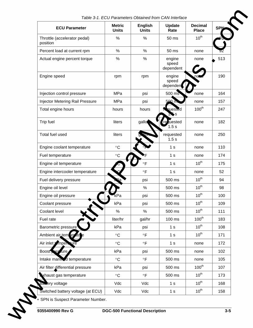
SAE J1939 Interface (Optional) A Controller Area Network (CAN) is a standard interface that allows communication between multiple controllers on a common network using a standard message protocol. DGC-500 controllers with a style number of XXJX have a CAN interface that supports the SAE J1939 message protocol. Applications using an engine-driven generator set controlled by a DGC-500 may also have an Engine Control Unit (ECU). The CAN interface allows the ECU and DGC-500 to communicate. The ECU reports operating information to the DGC-500 through the CAN interface. Operating parameters and diagnostic information, if supported by the ECU, are decoded and displayed for monitoring. The primary use of the CAN interface is to obtain engine operating parameters for monitoring speed, coolant temperature, oil pressure, coolant level, and engine hours without the need for direct connection to individual senders. Table 3-1 lists the ECU parameters and Table 3-2 lists the engine configuration parameters supported by the DGC-500 CAN interface. These parameters are transmitted via the CAN interface at preset intervals. The columns labeled Update Rate show the parameter transmission rates. This information can also be transmitted upon user request.
www . El
ectric
alPar
tMan
uals
. com
9355400990 Rev G DGC-500 Functional Description 3-5
Table 3-1. ECU Parameters Obtained from CAN Interface
ECU Parameter Metric Units
English Units
Update Rate
Decimal Place SPN ∗
Throttle (accelerator pedal) position
% % 50 ms 10th 91
Percent load at current rpm % % 50 ms none 92
Actual engine percent torque % % engine speed
dependent
none 513
Engine speed rpm rpm engine speed
dependent
none 190
Injection control pressure MPa psi 500 ms none 164
Injector Metering Rail Pressure MPa psi 500 ms none 157
Total engine hours hours hours requested 1.5 s
100th 247
Trip fuel liters gallons requested 1.5 s
none 182
Total fuel used liters gallons requested 1.5 s
none 250
Engine coolant temperature °C °F 1 s none 110
Fuel temperature °C °F 1 s none 174
Engine oil temperature °C °F 1 s 10th 175
Engine intercooler temperature °C °F 1 s none 52
Fuel delivery pressure kPa psi 500 ms 10th 94
Engine oil level % % 500 ms 10th 98
Engine oil pressure kPa psi 500 ms 10th 100
Coolant pressure kPa psi 500 ms 10th 109
Coolant level % % 500 ms 10th 111
Fuel rate liter/hr gal/hr 100 ms 100th 183
Barometric pressure kPa psi 1 s 10th 108
Ambient air temperature °C °F 1 s 10th 171
Air inlet temperature °C °F 1 s none 172
Boost pressure kPa psi 500 ms none 102
Intake manifold temperature °C °F 500 ms none 105
Air filter differential pressure kPa psi 500 ms 100th 107
Exhaust gas temperature °C °F 500 ms 10th 173
Battery voltage Vdc Vdc 1 s 10th 168
Switched battery voltage (at ECU) Vdc Vdc 1 s 10th 158
∗ SPN is Suspect Parameter Number.
www . El
ectric
alPar
tMan
uals
. com
3-6 DGC-500 Functional Description 9355400990 Rev G
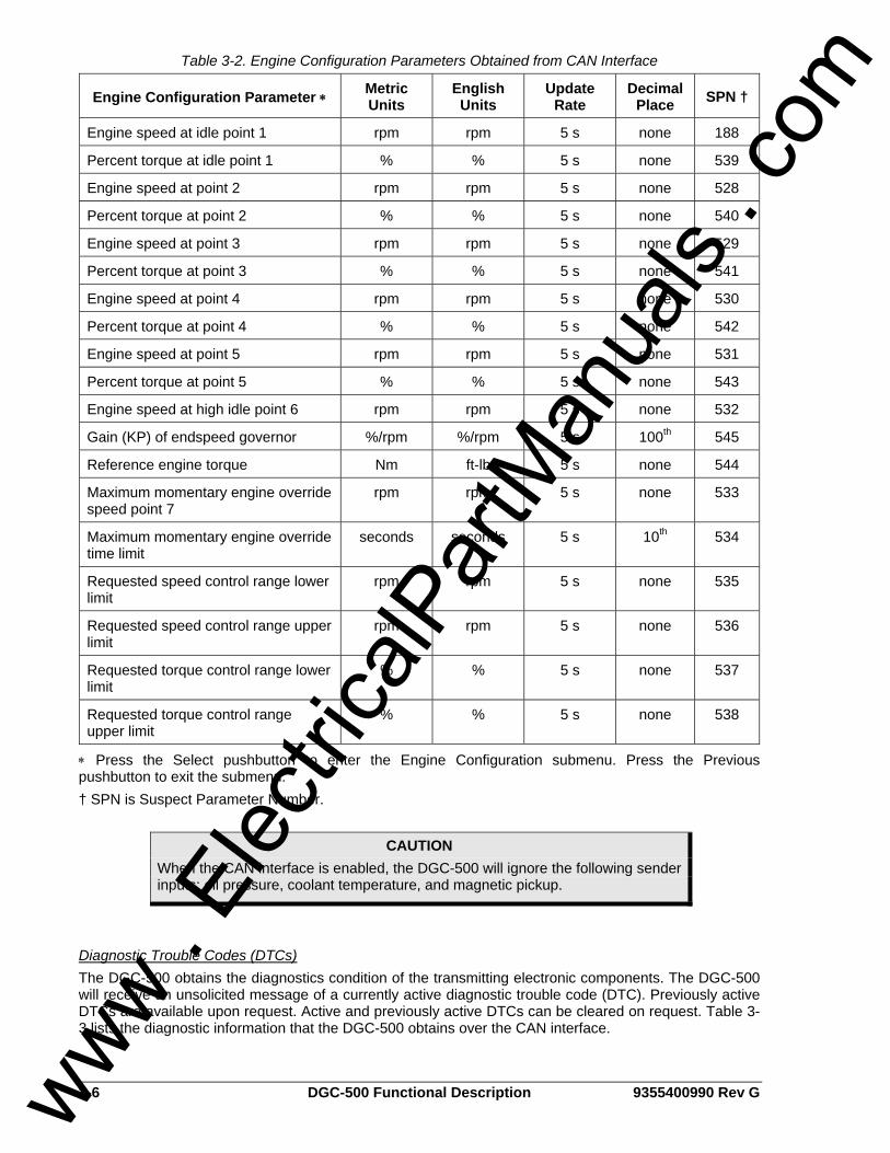
Table 3-2. Engine Configuration Parameters Obtained from CAN Interface
Engine Configuration Parameter ∗ Metric Units
English Units
Update Rate
Decimal Place SPN †
Engine speed at idle point 1 rpm rpm 5 s none 188
Percent torque at idle point 1 % % 5 s none 539
Engine speed at point 2 rpm rpm 5 s none 528
Percent torque at point 2 % % 5 s none 540
Engine speed at point 3 rpm rpm 5 s none 529
Percent torque at point 3 % % 5 s none 541
Engine speed at point 4 rpm rpm 5 s none 530
Percent torque at point 4 % % 5 s none 542
Engine speed at point 5 rpm rpm 5 s none 531
Percent torque at point 5 % % 5 s none 543
Engine speed at high idle point 6 rpm rpm 5 s none 532
Gain (KP) of endspeed governor %/rpm %/rpm 5 s 100th 545
Reference engine torque Nm ft-lb 5 s none 544
Maximum momentary engine override speed point 7
rpm rpm 5 s none 533
Maximum momentary engine override time limit
seconds seconds 5 s 10th 534
Requested speed control range lower limit
rpm rpm 5 s none 535
Requested speed control range upper limit
rpm rpm 5 s none 536
Requested torque control range lower limit
% % 5 s none 537
Requested torque control range upper limit
% % 5 s none 538
∗ Press the Select pushbutton to enter the Engine Configuration submenu. Press the Previous pushbutton to exit the submenu. † SPN is Suspect Parameter Number.
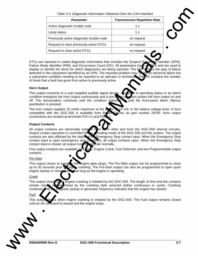
Diagnostic Trouble Codes (DTCs) The DGC-500 obtains the diagnostics condition of the transmitting electronic components. The DGC-500 will receive an unsolicited message of a currently active diagnostic trouble code (DTC). Previously active DTCs are available upon request. Active and previously active DTCs can be cleared on request. Table 3-3 lists the diagnostic information that the DGC-500 obtains over the CAN interface.
CAUTION When the CAN interface is enabled, the DGC-500 will ignore the following sender inputs: oil pressure, coolant temperature, and magnetic pickup.
www . El
ectric
alPar
tMan
uals
. com
9355400990 Rev G DGC-500 Functional Description 3-7
Table 3-3. Diagnostic Information Obtained Over the CAN Interface
Parameter Transmission Repetition Rate
Active diagnostic trouble code 1 s
Lamp status 1 s
Previously active diagnostic trouble code on request
Request to clear previously active DTCs on request
Request to clear active DTCs on request
DTCs are reported in coded diagnostic information that includes the Suspect Parameter Number (SPN), Failure Mode Identifier (FMI), and Occurrence Count (OC). All parameters have an SPN and are used to display or identify the items for which diagnostics are being reported. The FMI defines the type of failure detected in the subsystem identified by an SPN. The reported problem may not be an electrical failure but a subsystem condition needing to be reported to an operator or technician. The OC contains the number of times that a fault has gone from active to previously active.
Horn Output This output connects to a user-supplied audible signal device. A change in operating status or an alarm condition energizes the horn output continuously and a pre-alarm condition pulses the horn output on and off. The annunciation continues until the condition subsides or until the front-panel Alarm Silence pushbutton is pressed. The horn output supplies 15 mAdc maximum at the lesser of 24 Vdc or the battery voltage level. A horn compatible with the DGC-500 is available from Basler Electric as part number 29760. Horn output connections are located at terminals P24 (+) and P25 (–).
Output Contacts All output contacts are electrically isolated from each other and from the DGC-500 internal circuitry. Output contact operation is controlled by the operating mode of the DGC-500 and the system. The output contacts are also affected by the status of the Emergency Stop contact input. When the Emergency Stop contact input is open (emergency stop condition), all output contacts open. When the Emergency Stop contact input is closed, all output contacts operate normally. Five output contacts are available: Pre-Start, Engine Crank, Fuel Solenoid, and two Programmable output contacts.
Pre-Start This output closes to energize the engine glow plugs. The Pre-Start output can be programmed to close up to 30 seconds prior to engine cranking. The Pre-Start output can also be programmed to open upon engine startup or remain closed as long as the engine is operating.
Crank This output closes when engine cranking is initiated by the DGC-500. The length of time that the contacts remain closed is determined by the cranking style selected (either continuous or cycle). Cranking continues until the magnetic pickup or generator frequency indicates that the engine has started.
Fuel This output closes when engine cranking is initiated by the DGC-500. The Fuel output remains closed until an off command is issued and the engine stops.
www . El
ectric
alPar
tMan
uals
. com
3-8 DGC-500 Functional Description 9355400990 Rev G
Programmable Two programmable outputs (PROGRAM OUTPUT1, 2) can be user-configured to close for a variety of conditions. Either programmable output can be programmed to close during any of the following operating conditions. • Cooldown timer active • EPS supplying load • Pre-start condition in effect • Switch not in Auto
• Programmable Input 1 closed • Programmable Input 2 closed • Programmable Input 3 closed
Either of the programmable outputs can be configured to give a pre-alarm indication by closing during any of the following pre-alarm conditions. • Battery charger failure • Battery overvoltage • Fuel leak • Fuel leak/sender failure • High coolant temperature • Low battery voltage
• Low coolant level • Low coolant temperature • Low fuel • Low oil pressure • Scheduled maintenance due • Weak battery voltage
Either of the programmable outputs can be configured to give an alarm indication by closing during any of the following alarm conditions. • Battery charger • Coolant temperature sender failure • Emergency stop • Fuel leak • High coolant temperature • Loss of voltage sender failure • Low coolant level
• Low fuel • Low oil pressure • MPU speed sender failure • Oil pressure sender failure • Overcrank • Overspeed
SOFTWARE OPERATION Embedded software controls all aspects of DGC-500 operation. DGC-500 software controls power-up initiation, HMI configuration, engine cranking, contact input monitoring, fault detection and annunciation, system parameter monitoring, output contact control, and communication.
Power-Up Sequence When battery power is applied, the DGC-500 initiates a power-up sequence. During power-up, DGC-500 memory is checked and the LCD displays the embedded software version followed by a prompt to set the real-time clock. Then, all configuration data stored in nonvolatile EEPROM (electronically erasable programmable read-only memory) is brought into main memory and the DGC-500 begins operating in Normal mode. When operating in Normal mode, all enabled functions are active and all inputs are monitored.
Cranking The DGC-500 can be programmed for either continuous engine cranking or cycle engine cranking.
NOTE The run-time counter and maintenance timer values are updated in volatile memory once per minute. Updated values are saved to nonvolatile memory when the Auto/Off/Run mode of operation is changed. Additionally, while the engine is running, the run-time counter value is saved to nonvolatile memory every 15 minutes. If the battery power source fails during DGC-500 operation, these values are not updated and the changes made after the last save operation to nonvolatile memory are irretrievably lost.
www . El
ectric
alPar
tMan
uals
. com
9355400990 Rev G DGC-500 Functional Description 3-9
Continuous Cranking If desired, engine cranking can be delayed from zero to 30 seconds after initiating engine startup. When continuous engine cranking is initiated, cranking is sustained for a user-adjustable period of one to 60 seconds. A crank disconnect limit setting (10 to 100% of nominal engine speed) selects the desired engine speed above which cranking is terminated.
Cycle Cranking If desired, engine cranking can be delayed from zero to 30 seconds after initiating engine startup. When cycle engine cranking is initiated, five to 15 seconds of cranking is followed by an equal number of seconds of rest. A maximum of seven cranking cycles (five cycles for NFPA compliant units) are allowed by the DGC-500. A crank disconnect limit setting (10 to 100% of nominal engine speed) selects the desired engine speed above which cranking is terminated.
Pre-Alarms A pre-alarm is annunciated when a condition programmed to trigger a pre-alarm is met. When a pre-alarm condition exists, the front panel Alarm indicator flashes on and off and the Horn output (if enabled through BESTCOMS) alternates between an energized and de-energized state. The audible alarm is reset by pressing the front panel Alarm Silence pushbutton. Active pre-alarms for oil pressure, fuel level, coolant temperature, and battery voltage are displayed on the main display of the LCD. The LCD annunciates an active pre-alarm by alternating between the current parameter value and a blacked-out field for that value. All other pre-alarms are displayed in sequence through the alternate mode display. Each DGC-500 pre-alarm is described in the following paragraphs.
Low Oil Pressure A low oil pressure pre-alarm occurs when the engine oil pressure decreases below the setpoint programmed in BESTCOMS. The low oil pressure pre-alarm has a setting range of 3 to 150 psi or 20 to 1,035 kPa. A 10-second activation time delay prevents low oil pressure annunciation during engine startup.
Low Fuel A low fuel pre-alarm occurs when the fuel level decreases below the setpoint programmed in BESTCOMS. The low fuel pre-alarm has a setting range of 10 to 100 percent.
High Coolant Temperature A high coolant temperature pre-alarm occurs when the engine coolant temperature exceeds the setpoint programmed in BESTCOMS. The high coolant temperature pre-alarm has a setting range of 100 to 280°F or 38 to 138°C. A 60-second activation time delay prevents high coolant temperature annunciation during system startup.
Low Coolant Temperature A low coolant temperature pre-alarm occurs when the engine coolant temperature decreases below the setpoint programmed in BESTCOMS. The low coolant temperature pre-alarm has a setting range of 50 to 100°F or 10 to 38°C.
Battery Overvoltage A battery overvoltage pre-alarm occurs when the battery overvoltage pre-alarm function is enabled in BESTCOMS and the battery voltage level exceeds 30 Vdc for 24 Vdc systems or 15 Vdc for 12 Vdc systems.
Low Battery Voltage A low battery voltage pre-alarm occurs when the battery voltage decreases below the low battery voltage setpoint for the duration of the low battery voltage time delay setting. Both settings are made in BESTCOMS. The low battery voltage setpoint has a setting range of 12 to 24 Vdc for 24 Vdc systems and 6 to 12 Vdc for 12 Vdc systems. The low battery voltage time delay has a setting range of 1 to 10 seconds.
Weak Battery Voltage A weak battery voltage pre-alarm occurs when the battery voltage decreases below the weak battery voltage setpoint for the duration of the weak battery voltage time delay setting. Both settings are made in BESTCOMS. The weak battery voltage setpoint has a setting range of 8 to 16 Vdc for 24 Vdc systems www .
Elec
tricalP
artM
anua
ls . c
om
3-10 DGC-500 Functional Description 9355400990 Rev G
and 4 to 8 Vdc for 12 Vdc systems. The weak battery voltage time delay has a setting range of 1 to 10 seconds.
Maintenance Interval A maintenance interval pre-alarm occurs when the DGC-500 maintenance timer counts down to zero from the maintenance interval setting programmed in BESTCOMS. The maintenance interval duration has a setting range of zero to 5,000 hours.
Battery Charger Failure A battery charger failure pre-alarm occurs when one of the three DGC-500 programmable contact inputs detects a contact closure due to a battery charger failure. In order for a battery charger failure pre-alarm to occur, the battery charger failure pre-alarm function must be enabled in BESTCOMS and one of the three programmable inputs must be programmed as a battery charger failure pre-alarm input. Refer to Section 4, BESTCOMS Software for information about configuring the programmable contact inputs.
Fuel Level Sender Failure A fuel level sender failure pre-alarm occurs when an open circuit or short circuit is detected across the DGC-500 fuel level transducer terminals and a fuel level sender failure is programmed in BESTCOMS to cause a pre-alarm.
MPU Failure An MPU (magnetic pickup) failure pre-alarm occurs when MPU-GEN is selected as the generator speed signal source, the MPU signal is lost, and the Global Sender Failure Alarm time delay expires.
Active DTC When CAN and DTC support are both enabled, an “active DTC” pre-alarm may be enabled (through BESTCOMS) to announce the presence of a condition that is causing a DTC to be sent from the ECU to the DGC-500.
CAN Failure A CAN failure annunciation may be enabled only when the CAN interface is enabled. The CAN interface is enabled through BESTCOMS. When configured to alarm, annunciation occurs when CAN communication stops due to a lost connection between the DGC-500 and ECU, or an ECU malfunction. If CAN communication is lost and the annunciation is a pre-alarm, a screen stating the pre-alarm will appear in the Alternate Display menu. This screen will be viewable only when the pre-alarm is active.
Audible Alarm A pre-alarm is annunciated through the DGC-500 Horn output when the audible alarm feature is enabled in BESTCOMS. When the audible alarm is enabled, a pre-alarm condition causes the horn output to alternate between an energized and de-energized state.
Alarms An alarm is annunciated when a condition programmed to trigger an alarm is detected. When an alarm condition exists, the front panel Alarm indicator lights, the Horn output energizes, and the cause of the alarm is displayed on the LCD. An alarm condition stops the engine by opening the Fuel output contact. Each DGC-500 alarm is described in the following paragraphs.
Low Oil Pressure A low oil pressure alarm occurs when the engine oil pressure decreases below the low oil pressure alarm setpoint for the duration of the low oil pressure time delay setting. Both settings are made in BESTCOMS. When a low oil pressure alarm occurs, the LCD indicates LOW OIL PRESSURE and the current low oil pressure alarm setting. A 10-second activation time delay prevents low oil pressure annunciation during engine startup. The low oil pressure setpoint has a setting range of 3 to 150 psi or 20 to 1,035 kPa and the low oil pressure time delay has a setting range of 5 to 15 seconds.
Low Fuel Level A low fuel level alarm occurs when the fuel level decreases below the setpoint programmed in BESTCOMS. When a low fuel level alarm occurs, the LCD indicates LOW FUEL LEVEL and the current low fuel level alarm setting.
www . El
ectric
alPar
tMan
uals
. com
9355400990 Rev G DGC-500 Functional Description 3-11
The low fuel level setpoint has a setting range of zero to 100 percent.
High Coolant Temperature A high coolant temperature alarm occurs when the coolant temperature exceeds the setpoint programmed in BESTCOMS. When a high coolant temperature alarm occurs, the LCD indicates HIGH COOLANT TEMP and the current high coolant temperature setting. A 60-second activation time delay prevents high coolant temperature annunciation during system startup. The high coolant temperature setpoint has a setting range of 100 to 280°F or 38 to 138°C.
Overspeed An overspeed alarm occurs when the engine speed exceeds the overspeed setpoint for the duration of the overspeed time delay. Both settings are made in BESTCOMS. When an overspeed alarm occurs, the LCD indicates OVERSPEED and the current overspeed setting. The overspeed setpoint has a setting range of 105 to 140 percent and the overspeed time delay has a setting range of zero to 500 milliseconds.
Loss of Generator Voltage A loss of generator voltage alarm can occur only when the loss of generator voltage alarm is enabled in BESTCOMS. When the sensed generator voltage decreases below 1.5 Vac for the duration of the global sender failure alarm time delay, a loss of generator voltage alarm occurs. The global sender failure alarm time delay is adjustable from 1 to 10 seconds.
Oil Pressure Sender Failure An oil pressure sender failure alarm occurs when the DGC-500 oil pressure transducer input senses a sender failure for the duration of the global sender failure alarm time delay. The oil pressure sender failure alarm is enabled and the global sender failure alarm time delay is set in BESTCOMS.
Coolant Temperature Sender Failure A coolant temperature sender failure alarm occurs when the DGC-500 coolant temperature transducer input senses a sender failure for the duration of the coolant temperature alarm delay time. The coolant temperature sender failure alarm is enabled and the coolant temperature alarm delay is set in BESTCOMS. The coolant temperature alarm delay is adjustable from 5 to 30 minutes in 5 minute increments.
Speed Source Failure A speed source failure can occur for either of two conditions. If MPU (magnetic pickup) is selected as the generator speed signal source and the MPU signal is lost, a speed source failure alarm will occur. If GEN FREQ (generator frequency) is selected as the generator speed signal source and a loss of generator frequency is detected, a speed source failure alarm will occur.
CAN Failure (If Equipped) A CAN failure annunciation may be enabled only when the CAN interface is enabled. The CAN interface is enabled through BESTCOMS. When configured to pre-alarm, annunciation occurs when CAN communication stops due to a lost connection between the DGC-500 and ECU, or an ECU malfunction. If CAN communication is lost and the annunciation is configured as an alarm, then a normal alarm sequence will occur, including a CANBUS FAILURE message that appears on the HMI display.
Real-Time Clock The real-time clock supplies time and date information to the event log for the time stamping of events. Clock data is held in volatile memory; clock settings are lost when DGC-500 operating power is removed. When DGC-500 operating power is restored, the DGC-500 prompts the user to set the real-time clock. The DGC-500 keeps time in 24-hour mode and uses the HH:MM:SS format. The date format is MM/DD/YYYY. Adjustment for daylight saving time can be enabled or disabled. Clock settings may be viewed and entered in BESTCOMS or at the front panel HMI.
Generator Run Statistics The DGC-500 compiles statistics for both individual generator run sessions and the cumulative total of all generator run sessions. Generator run statistics are stored in DGC-500 nonvolatile memory and displayed on the Run Statistics screen of BESTCOMS. When the DGC-500 and/or genset are commissioned, a date is entered for the DGC-500 to use as a starting point for tracking generator run
www . El
ectric
alPar
tMan
uals
. com
3-12 DGC-500 Functional Description 9355400990 Rev G
statistics. The logs for session run and cumulative run statistics track loaded run hours, unloaded run hours, and total run hours. Additionally, the cumulative run statistics log tracks the number of engine starts and the number of hours remaining until scheduled maintenance.
Event Log The event log maintains a history of system events in DGC-500 nonvolatile memory and displays the event record on the Event Log screen in BESTCOMS. System events are categorized by the event log into event types. The event log capacity is 30 event types. Each event type in the log contains an event identifier label, the number of occurrences for the event, and the time stamp of the most recent event occurrence. The time stamp displayed is user-selectable and can be real-time clock data or the elapsed engine hours. When an event type is logged, it occupies one entry (or row) in the log. If the same event type is logged again, it still only occupies one entry in the log. However, the log entry is updated with the number of occurrences and the Last Date/Time column is updated with the time stamp of the last occurrence. If the event log contains the maximum of 30 event types and a new event type is logged, the oldest event type in the log is overwritten with the new event type. The event types monitored by the event log are listed below. • Active DTC exists pre-alarm • Auto Start contact closed • Auxiliary input 1 closed • Auxiliary input 2 closed • Auxiliary input 3 closed • Battery charger failure pre-alarm • Battery overvoltage pre-alarm • CAN Bus failure pre-alarm • CAN Bus failure alarm • Coolant level sender failure • Coolant temperature sender failure alarm • DGC-500 protective shutdown • EE memory checksum error • Emergency stop alarm • Engine started • Flash checksum error • Fuel leak/sender failure pre-alarm • Generator phase imbalance detected • Generator overvoltage detected • Generator undervoltage detected • Generator overcurrent detected • Generator underfrequency detected
• Generator overfrequency detected • High coolant temperature pre-alarm • High coolant temperature alarm • Loss of voltage sender failure alarm • Low coolant level pre-alarm • Low fuel alarm • Low coolant level alarm • Low oil pressure alarm • Low battery voltage pre-alarm • Low oil pressure pre-alarm • Low coolant temperature pre-alarm • Low fuel pre-alarm • MPU speed sender failure alarm • Normal engine shutdown • Oil pressure sender failure alarm • Overcrank alarm • Overspeed alarm • Scheduled maintenance pre-alarm • Unknown shutdown (with ECU enabled,
engine stops without input from the DGC) • Weak battery voltage pre-alarm
Generator Protection Multifunction generator protection is provided on DGC-500 controller with style number XXX1. The DGC-500 can protect a generator against overvoltage, undervoltage, overfrequency, underfrequency, overcurrent, and phase imbalance.
Overvoltage (59) Two sets of overvoltage settings are provided: one for three-phase generator connections and one for single-phase generator connections. When the average of the three phase voltages (three-phase mode) or the average of the line-to-line voltage (single-phase mode) increases above the corresponding 59 pickup setting for the duration of the corresponding 59 time delay, an overvoltage condition is annunciated. Both overvoltage pickup settings have a range of 70 to 576 Vac and both overvoltage time delay settings have a range of 0 to 30 seconds. An overvoltage annunciation can be user-selected to trigger a pre-alarm (warning) or alarm (shutdown). An overvoltage annunciation can also be user-configured to close one or both of the programmable outputs. When a Single-Phase Override contact input is received, the DGC-500 automatically switches from the three-phase overvoltage settings to the single-phase overvoltage settings. www .
Elec
tricalP
artM
anua
ls . c
om
9355400990 Rev G DGC-500 Functional Description 3-13
Undervoltage (27) Two sets of undervoltage settings are provided: one for three-phase generator connections and one for single-phase generator connections. When the average of the three-phase voltage (three-phase mode) or the average of the line-to-line voltage (single-phase mode) decreases below the corresponding 27 pickup setting for the duration of the corresponding 27 time delay, an undervoltage condition is annunciated. Both undervoltage pickup settings have a range of 70 to 576 Vac and both undervoltage time delay settings have a range of 0 to 30 seconds. A frequency-based inhibit setting prevents a 27 trip from occurring during an underfrequency condition associated with system startup. The frequency-based inhibit function has a setting range of 20 to 400 hertz. An undervoltage annunciation can be user-selected to trigger a pre-alarm (warning) or alarm (shutdown). An undervoltage annunciation can also be user-configured to close one or both of the programmable outputs. When a Single-Phase Override contact input is received, the DGC-500 automatically switches from the three-phase undervoltage settings to the single-phase undervoltage settings.
Frequency (81) Two sets of frequency settings are provided: one for underfrequency (81U) protection and one for overfrequency (81O) protection. When the generator frequency decreases below the 81U pickup setting for the duration of the 81U time delay, an underfrequency condition is annunciated. When the generator frequency increases above the 81O pickup setting for the duration of the 81O time delay, an overfrequency condition is annunciated. For 50/60 hertz sensing, the 81U and 81O functions have a setting range of 45 to 65 hertz. For 400 hertz sensing, the 81U and 81O functions have a setting range of 360 to 440 hertz. The time delay for the 81U and 81O functions has a setting range of 0 to 30 seconds. A voltage-based inhibit setting prevents an 81U trip from occurring during an undervoltage condition associated with system startup. The voltage-based inhibit function has a setting range of 70 to 576 Vac. Underfrequency and overfrequency conditions can be user-selected to trigger a pre-alarm (warning) or alarm (shutdown). An underfrequency and/or overfrequency condition can also be user-configured to close one or both of the programmable outputs.
Overcurrent (51) Two sets of overcurrent settings are provided: one for three-phase generator connections and one for single-phase generator connections. When any of the phase currents increase above the 51 pickup setting for the duration of the 51 time delay, an overcurrent condition is annunciated. Controllers with 1 A current sensing (style X1XX) have an overcurrent pickup range of 0.18 to 1.18 Aac. Controllers with 5 A current sensing (style X5XX) have an overcurrent pickup range of 0.9 to 7.75 Aac. The overcurrent time delay is controlled by a curve setting and time dial setting. The curve setting can be set at F, Fixed, or one of 16 inverse timing characteristic curves can be selected. When the F, Fixed curve setting is selected, the time dial setting (adjustable from 0 to 30 seconds) determines the overcurrent time delay with no regard to the generator current level. When one of the 16 inverse timing characteristics curves selected, the time dial setting (adjustable from a multiplier of 0 to 9.9) along with the level of measured generator current determines the overcurrent time delay. The available characteristic curves is listed below and illustrated in Appendix A, Time Overcurrent Characteristic Curves. • S1, Short Inverse • S2, Short Inverse • L1, Long Inverse • L2, Long Inverse • D, Definite • M, Moderately Inverse • I1, Inverse • I2, Inverse
• V1, Very Inverse • V2, Very Inverse • E1, Extremely Inverse • E2, Extremely Inverse • A, Standard Inverse • B, Very Inverse • C, Extremely Inverse • G, Long Inverse
www . El
ectric
alPar
tMan
uals
. com
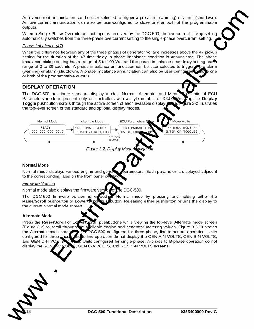
3-14 DGC-500 Functional Description 9355400990 Rev G
An overcurrent annunciation can be user-selected to trigger a pre-alarm (warning) or alarm (shutdown). An overcurrent annunciation can also be user-configured to close one or both of the programmable outputs. When a Single-Phase Override contact input is received by the DGC-500, the overcurrent pickup setting automatically switches from the three-phase overcurrent setting to the single-phase overcurrent setting.
Phase Imbalance (47) When the difference between any of the three phases of generator voltage increases above the 47 pickup setting for the duration of the 47 time delay, a phase imbalance condition is annunciated. The phase imbalance pickup setting has a range of 5 to 100 Vac and the phase imbalance time delay setting has a range of 0 to 30 seconds. A phase imbalance annunciation can be user-selected to trigger a pre-alarm (warning) or alarm (shutdown). A phase imbalance annunciation can also be user-configured to close one or both of the programmable outputs.
DISPLAY OPERATION The DGC-500 has three standard display modes: Normal, Alternate, and Menu. The optional ECU Parameters mode is present only on controllers with a style number of XXJX. Pressing the Display Toggle pushbutton scrolls through the active screen of each available display mode. Figure 3-2 illustrates the top-level screen of the standard and optional display modes.
Figure 3-2. Display Mode Navigation
Normal Mode Normal mode displays various engine and generator parameters. Each parameter is displayed adjacent to the corresponding label on the front panel overlay.
Firmware Version Normal mode also displays the firmware version of the DGC-500. The DGC-500 firmware version is viewed in Normal mode by pressing and holding either the Raise/Scroll pushbutton or Lower/Scroll pushbutton. Releasing either pushbutton returns the display to the current Normal mode screen.
Alternate Mode Press the Raise/Scroll or Lower/Scroll pushbuttons while viewing the top-level Alternate mode screen (Figure 3-2) to scroll through the available engine and generator metering values. Figure 3-3 illustrates the Alternate mode screens for a DGC-500 configured for three-phase, line-to-neutral operation. Units configured for three-phase, line-to-line operation do not display the GEN A-N VOLTS, GEN B-N VOLTS, and GEN C-N VOLTS screens. Units configured for single-phase, A-phase to B-phase operation do not display the GEN B-C VOLTS, GEN C-A VOLTS, and GEN C-N VOLTS screens.
www . El
ectric
alPar
tMan
uals
. com
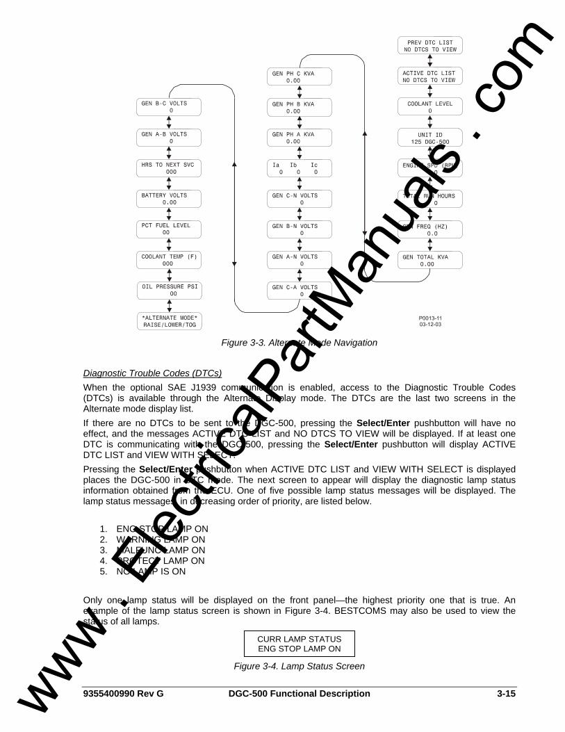
9355400990 Rev G DGC-500 Functional Description 3-15
Figure 3-3. Alternate Mode Navigation
Diagnostic Trouble Codes (DTCs) When the optional SAE J1939 communication is enabled, access to the Diagnostic Trouble Codes (DTCs) is available through the Alternate Display mode. The DTCs are the last two screens in the Alternate mode display list. If there are no DTCs to be sent to the DGC-500, pressing the Select/Enter pushbutton will have no effect, and the messages ACTIVE DTC LIST and NO DTCS TO VIEW will be displayed. If at least one DTC is communicating with the DGC-500, pressing the Select/Enter pushbutton will display ACTIVE DTC LIST and VIEW WITH SELECT. Pressing the Select/Enter pushbutton when ACTIVE DTC LIST and VIEW WITH SELECT is displayed places the DGC-500 in DTC mode. The next screen to appear will display the diagnostic lamp status information obtained from the ECU. One of five possible lamp status messages will be displayed. The lamp status messages, in decreasing order of priority, are listed below.
1. ENG STOP LAMP ON 2. WARNING LAMP ON 3. MALFUNC LAMP ON 4. PROTECT LAMP ON 5. NO LAMP IS ON
Only one lamp status will be displayed on the front panel—the highest priority one that is true. An example of the lamp status screen is shown in Figure 3-4. BESTCOMS may also be used to view the status of all lamps.
Figure 3-4. Lamp Status Screen
CURR LAMP STATUS ENG STOP LAMP ON
www . El
ectric
alPar
tMan
uals
. com
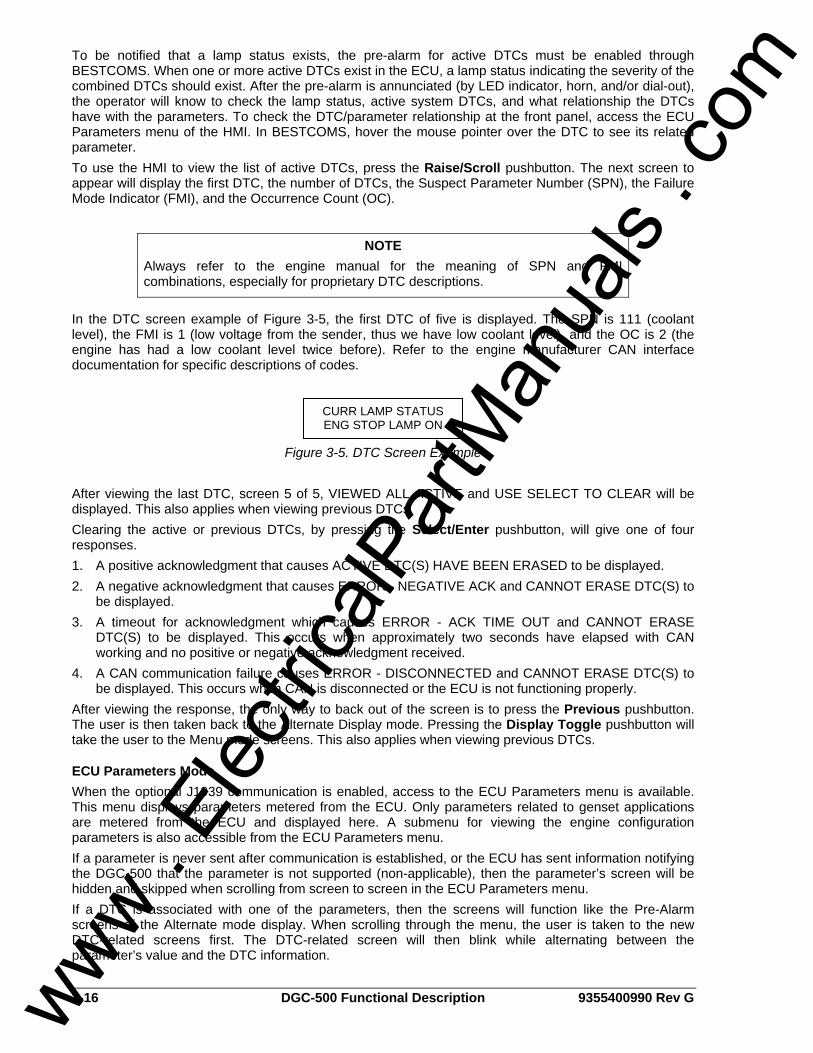
3-16 DGC-500 Functional Description 9355400990 Rev G
To be notified that a lamp status exists, the pre-alarm for active DTCs must be enabled through BESTCOMS. When one or more active DTCs exist in the ECU, a lamp status indicating the severity of the combined DTCs should exist. After the pre-alarm is annunciated (by LED indicator, horn, and/or dial-out), the operator will know to check the lamp status, active system DTCs, and what relationship the DTCs have with the parameters. To check the DTC/parameter relationship at the front panel, access the ECU Parameters menu of the HMI. In BESTCOMS, hover the mouse pointer over the DTC to see its related parameter. To use the HMI to view the list of active DTCs, press the Raise/Scroll pushbutton. The next screen to appear will display the first DTC, the number of DTCs, the Suspect Parameter Number (SPN), the Failure Mode Indicator (FMI), and the Occurrence Count (OC).
In the DTC screen example of Figure 3-5, the first DTC of five is displayed. The SPN is 111 (coolant level), the FMI is 1 (low voltage from the sender, thus we have low coolant level), and the OC is 2 (the engine has had a low coolant level twice before). Refer to the engine manufacturer CAN interface documentation for specific descriptions of codes.
Figure 3-5. DTC Screen Example
After viewing the last DTC, screen 5 of 5, VIEWED ALL ACTIVE and USE SELECT TO CLEAR will be displayed. This also applies when viewing previous DTCs. Clearing the active or previous DTCs, by pressing the Select/Enter pushbutton, will give one of four responses. 1. A positive acknowledgment that causes ACTIVE DTC(S) HAVE BEEN ERASED to be displayed. 2. A negative acknowledgment that causes ERROR - NEGATIVE ACK and CANNOT ERASE DTC(S) to
be displayed. 3. A timeout for acknowledgment which causes ERROR - ACK TIME OUT and CANNOT ERASE
DTC(S) to be displayed. This occurs when approximately two seconds have elapsed with CAN working and no positive or negative acknowledgment received.
4. A CAN communication failure causes ERROR - DISCONNECTED and CANNOT ERASE DTC(S) to be displayed. This occurs when CAN is disconnected or the ECU is not functioning properly.
After viewing the response, the only way to back out of the screen is to press the Previous pushbutton. The user is then taken back to the Alternate Display mode. Pressing the Display Toggle pushbutton will take the user to the Menu mode screens. This also applies when viewing previous DTCs.
ECU Parameters Mode When the optional J1939 communication is enabled, access to the ECU Parameters menu is available. This menu displays parameters metered from the ECU. Only parameters related to genset applications are metered from the ECU and displayed here. A submenu for viewing the engine configuration parameters is also accessible from the ECU Parameters menu. If a parameter is never sent after communication is established, or the ECU has sent information notifying the DGC-500 that the parameter is not supported (non-applicable), then the parameter’s screen will be hidden and skipped when scrolling from screen to screen in the ECU Parameters menu. If a DTC is associated with one of the parameters, then the screens will function like the Pre-Alarm screens of the Alternate mode display. When scrolling through the menu, the user is taken to the new DTC-related screens first. The DTC-related screen will then blink while alternating between the parameter’s value and the DTC information.
NOTE Always refer to the engine manual for the meaning of SPN and FMI combinations, especially for proprietary DTC descriptions.
CURR LAMP STATUS ENG STOP LAMP ON
www . El
ectric
alPar
tMan
uals
. com
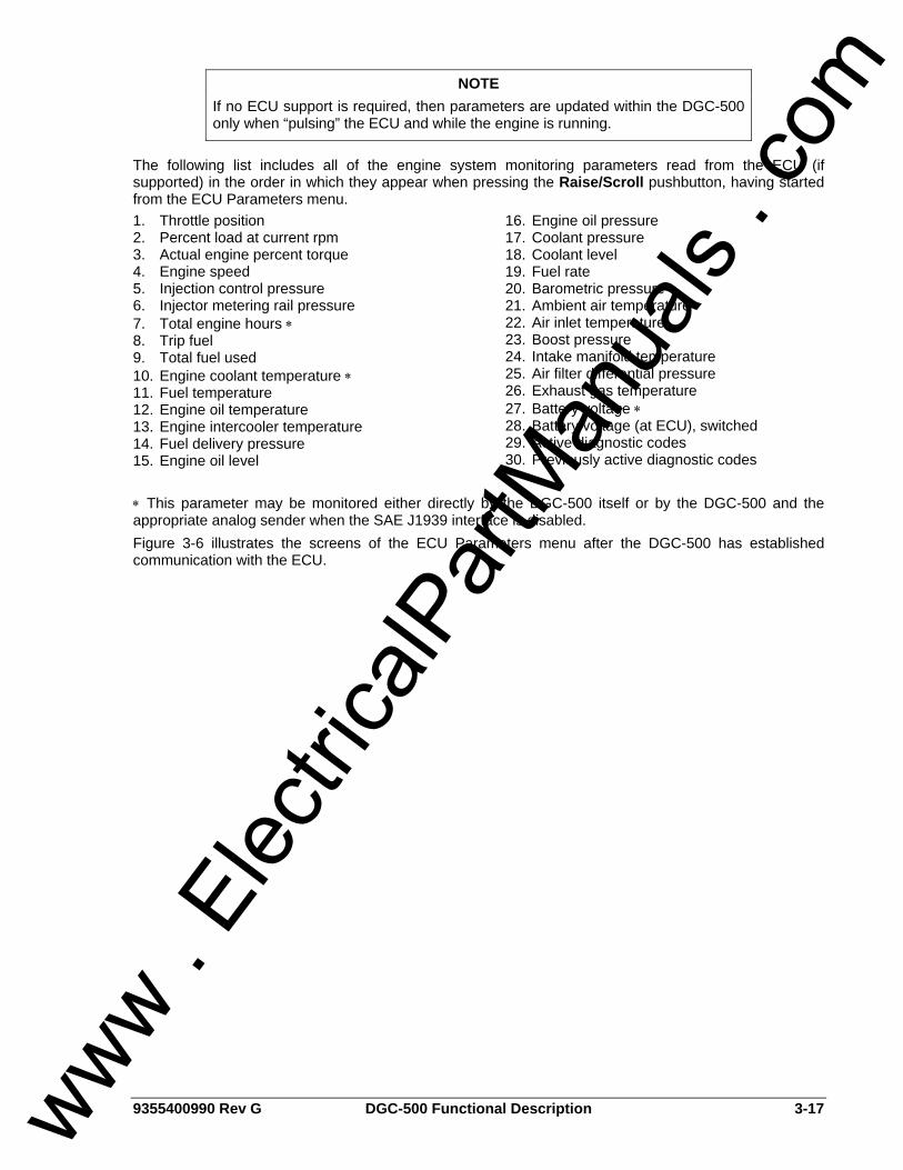
9355400990 Rev G DGC-500 Functional Description 3-17
The following list includes all of the engine system monitoring parameters read from the ECU (if supported) in the order in which they appear when pressing the Raise/Scroll pushbutton, having started from the ECU Parameters menu. 1. Throttle position 2. Percent load at current rpm 3. Actual engine percent torque 4. Engine speed 5. Injection control pressure 6. Injector metering rail pressure 7. Total engine hours ∗ 8. Trip fuel 9. Total fuel used 10. Engine coolant temperature ∗ 11. Fuel temperature 12. Engine oil temperature 13. Engine intercooler temperature 14. Fuel delivery pressure 15. Engine oil level
16. Engine oil pressure 17. Coolant pressure 18. Coolant level 19. Fuel rate 20. Barometric pressure 21. Ambient air temperature 22. Air inlet temperature 23. Boost pressure 24. Intake manifold temperature 25. Air filter differential pressure 26. Exhaust gas temperature 27. Battery voltage ∗ 28. Battery voltage (at ECU), switched 29. Active diagnostic codes 30. Previously active diagnostic codes
∗ This parameter may be monitored either directly by the DGC-500 itself or by the DGC-500 and the appropriate analog sender when the SAE J1939 interface is disabled. Figure 3-6 illustrates the screens of the ECU Parameters menu after the DGC-500 has established communication with the ECU.
NOTE If no ECU support is required, then parameters are updated within the DGC-500 only when “pulsing” the ECU and while the engine is running.
www . El
ectric
alPar
tMan
uals
. com
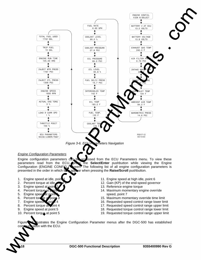
3-18 DGC-500 Functional Description 9355400990 Rev G
Figure 3-6. ECU Parameters Navigation
Engine Configuration Parameters Engine configuration parameters can be accessed from the ECU Parameters menu. To view these parameters read from the ECU, press the Select/Enter pushbutton while viewing the Engine Configuration (ENGINE CONFIG.) screen. The following list of all engine configuration parameters is presented in the order in which they appear when pressing the Raise/Scroll pushbutton. 1. Engine speed at idle, point 1 2. Percent torque at idle, point 1 3. Engine speed at point 2 4. Percent torque at point 2 5. Engine speed at point 3 6. Percent torque at point 3 7. Engine speed at point 4 8. Percent torque at point 4 9. Engine speed at point 5 10. Percent torque at point 5
11. Engine speed at high idle, point 6 12. Gain (KP) of the end-speed governor 13. Reference engine torque 14. Maximum momentary engine override
speed, point 7 15. Maximum momentary override time limit 16. Requested speed control range lower limit 17. Requested speed control range upper limit 18. Requested torque control range lower limit 19. Requested torque control range upper limit
Figure 3-7 illustrates the Engine Configuration Parameter menus after the DGC-500 has established communication with the ECU.
www . El
ectric
alPar
tMan
uals
. com
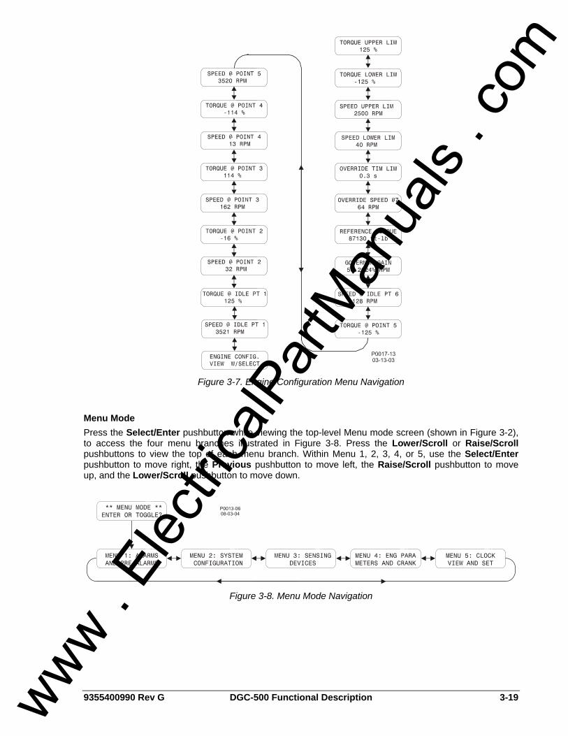
9355400990 Rev G DGC-500 Functional Description 3-19
Figure 3-7. Engine Configuration Menu Navigation
Menu Mode Press the Select/Enter pushbutton while viewing the top-level Menu mode screen (shown in Figure 3-2), to access the four menu branches illustrated in Figure 3-8. Press the Lower/Scroll or Raise/Scroll pushbuttons to view the top of each menu branch. Within Menu 1, 2, 3, 4, or 5, use the Select/Enter pushbutton to move right, the Previous pushbutton to move left, the Raise/Scroll pushbutton to move up, and the Lower/Scroll pushbutton to move down.
Figure 3-8. Menu Mode Navigation
www . El
ectric
alPar
tMan
uals
. com
3-20 DGC-500 Functional Description 9355400990 Rev G
Menu 1 DGC-500 pre-alarms and alarms are viewed and configured in Menu 1. Figure 3-9 illustrates the Menu 1 screens.
Menu 2 System configuration settings are viewed and configured in Menu 2. Figure 3-10 illustrates the Menu 2 screens.
Menu 3 DGC-500 calibration, transformer ratios, and transducer failure alarms, are viewed and configured in Menu 3. Figure 3-11 illustrates the Menu 3 screens. The menu screens associated with the calibration process are illustrated in Section 5, Installation, Calibration.
Menu 4 Engine cool-down time and cranking parameters are viewed and configured in Menu 4. Figure 3-12 illustrates the Menu 4 screens.
Menu 5 Real-time clock settings are viewed and set in Menu 5. Figure 3-13 illustrates the Menu 5 screens.
Exiting Menu Mode Pressing the Display Toggle pushbutton exits the Menu mode from any level and branch. When the Display Toggle pushbutton is used to exit Menu mode, the user’s place within the menu tree is saved. The display will return to the same screen the next time that Menu mode is entered. If the Display Toggle pushbutton is pressed before a new setting is saved, the existing setting is retained. Using the Previous pushbutton to back out of Menu mode ensures that the top-level Menu mode screen is viewed the next time Menu mode is entered.
Sleep Mode Sleep mode serves as a power saving feature. If the DGC-500 is in Off mode for more than 15 minutes, the front panel LEDs, LCD, and LCD backlight are turned off. The DGC-500 resumes normal display operation when any front panel button is pressed or the genset is started remotely via the ATS input. If needed, Sleep mode can be permanently disabled via BESTCOMS. Refer to Section 4, BESTCOMS Software for more information.
www . El
ectric
alPar
tMan
uals
. com
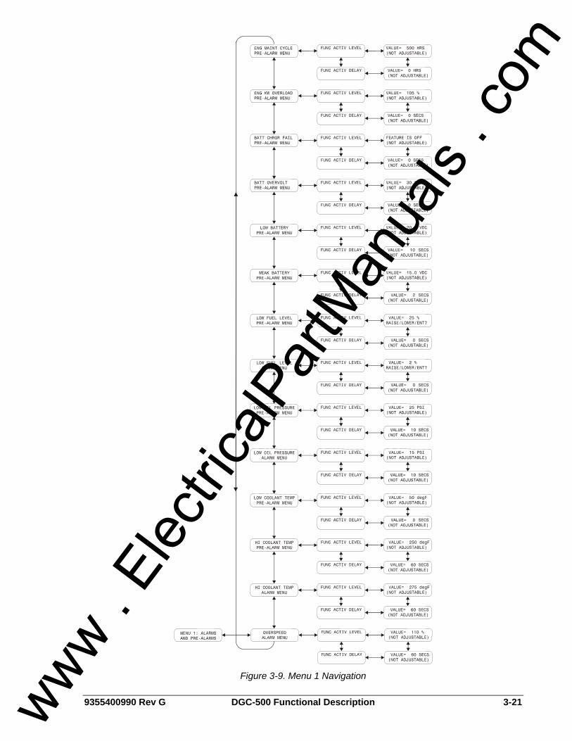
9355400990 Rev G DGC-500 Functional Description 3-21
Figure 3-9. Menu 1 Navigation
www . El
ectric
alPar
tMan
uals
. com
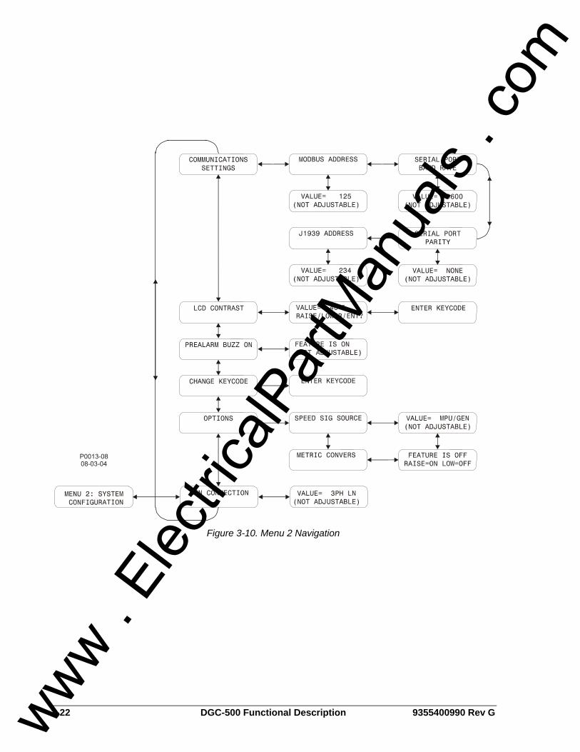
3-22 DGC-500 Functional Description 9355400990 Rev G
Figure 3-10. Menu 2 Navigation
www . El
ectric
alPar
tMan
uals
. com
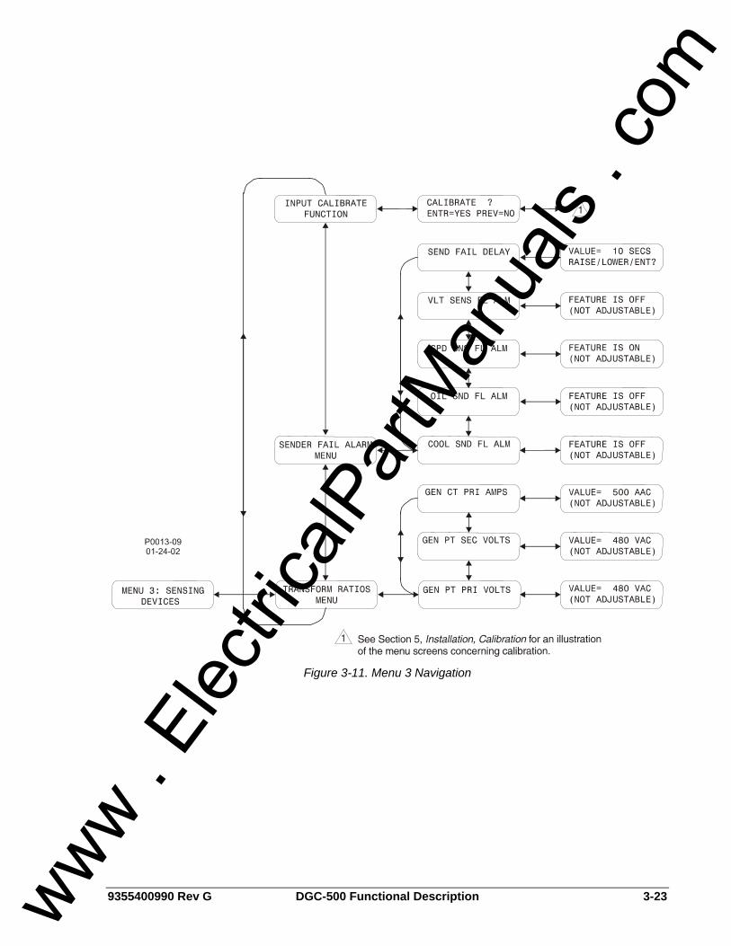
9355400990 Rev G DGC-500 Functional Description 3-23
Figure 3-11. Menu 3 Navigation
www . El
ectric
alPar
tMan
uals
. com

3-24 DGC-500 Functional Description 9355400990 Rev G
Figure 3-12. Menu 4 Navigation
Figure 3-13. Menu 5 Navigation
www . El
ectric
alPar
tMan
uals
. com
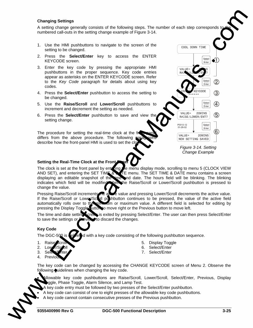
9355400990 Rev G DGC-500 Functional Description 3-25
Changing Settings A setting change generally consists of the following steps. The number of each step corresponds to the numbered call-outs in the setting change example of Figure 3-14. 1. Use the HMI pushbuttons to navigate to the screen of the
setting to be changed. 2. Press the Select/Enter key to access the ENTER
KEYCODE screen. 3. Enter the key code by pressing the appropriate HMI
pushbuttons in the proper sequence. Key code entries appear as asterisks on the ENTER KEYCODE screen. Refer to the Key Code paragraph for details about using key codes.
4. Press the Select/Enter pushbutton to access the setting to be changed.
5. Use the Raise/Scroll and Lower/Scroll pushbuttons to increment and decrement the setting as needed.
6. Press the Select/Enter pushbutton to save and view the setting change.
The procedure for setting the real-time clock at the front panel differs from the above procedure. The following paragraphs describe how the front-panel HMI is used to set the clock.
Figure 3-14. Setting Change Example
Setting the Real-Time Clock at the Front Panel The clock is set at the front panel by entering the menu display mode, scrolling to menu 5 (CLOCK VIEW AND SET), and entering the SET TIME & DATE menu. The SET TIME & DATE menu contains a screen displaying an editable snapshot of the time and date. The hours field will be blinking. The blinking indicates which field will be modified when the Raise/Scroll or Lower/Scroll pushbutton is pressed to change the value. Pressing Raise/Scroll increments the active value and pressing Lower/Scroll decrements the active value. If the Raise/Scroll or Lower/Scroll pushbutton continues to be pressed, the value of the active field automatically rolls over to the minimum or maximum value. A different field is selected for editing by pressing the Display Toggle button to move right or the Previous button to move left. The time and date setting screen is exited by pressing Select/Enter. The user can then press Select/Enter to save the settings or Previous to discard the changes.
Key Code The DGC-500 is delivered with a key code consisting of the following pushbutton sequence.
1. Raise/Scroll 2. Lower/Scroll 3. Select/Enter 4. Previous
5. Display Toggle 6. Select/Enter 7. Select/Enter
The key code can be changed by accessing the CHANGE KEYCODE screen of Menu 2. Observe the following guidelines when changing the key code.
• Allowable key code pushbuttons are Raise/Scroll, Lower/Scroll, Select/Enter, Previous, Display Toggle, Phase Toggle, Alarm Silence, and Lamp Test.
• A key code entry must be followed by two presses of the Select/Enter pushbutton. • A key code can consist of one to eight presses of the allowable key code pushbuttons. • A key code cannot contain consecutive presses of the Previous pushbutton.
www . El
ectric
alPar
tMan
uals
. com
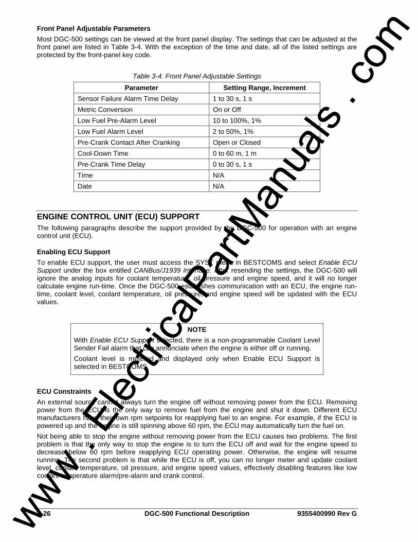
3-26 DGC-500 Functional Description 9355400990 Rev G
Front Panel Adjustable Parameters Most DGC-500 settings can be viewed at the front panel display. The settings that can be adjusted at the front panel are listed in Table 3-4. With the exception of the time and date, all of the listed settings are protected by the front-panel key code.
Table 3-4. Front Panel Adjustable Settings
Parameter Setting Range, Increment Sensor Failure Alarm Time Delay 1 to 30 s, 1 s Metric Conversion On or Off Low Fuel Pre-Alarm Level 10 to 100%, 1% Low Fuel Alarm Level 2 to 50%, 1% Pre-Crank Contact After Cranking Open or Closed Cool-Down Time 0 to 60 m, 1 m Pre-Crank Time Delay 0 to 30 s, 1 s Time N/A Date N/A
ENGINE CONTROL UNIT (ECU) SUPPORT The following paragraphs describe the support provided by the DGC-500 for operation with an engine control unit (ECU).
Enabling ECU Support To enable ECU support, the user must access the SYST menu in BESTCOMS and select Enable ECU Support under the box entitled CANBus/J1939 Interface. After resending the settings, the DGC-500 will ignore the analog inputs for coolant temperature, oil pressure and engine speed, and it will no longer calculate engine run-time. Once the DGC-500 establishes communication with an ECU, the engine run-time, coolant level, coolant temperature, oil pressure, and engine speed will be updated with the ECU values.
ECU Constraints An external source cannot always turn the engine off without removing power from the ECU. Removing power from the ECU is the only way to remove fuel from the engine and shut it down. Different ECU manufacturers have their own rpm setpoints for reapplying fuel to an engine. For example, if the ECU is powered up and the engine is still spinning above 60 rpm, the ECU may automatically turn the fuel on. Not being able to stop the engine without removing power from the ECU causes two problems. The first problem is that the only way to stop the engine is to turn the ECU off and wait for the engine speed to decrease below 60 rpm before reapplying ECU operating power. Otherwise, the engine will resume running. The second problem is that while the ECU is off, you can no longer meter and update coolant level, coolant temperature, oil pressure, and engine speed values, effectively disabling features like low coolant temperature alarm/pre-alarm and crank control.
NOTE With Enable ECU Support selected, there is a non-programmable Coolant Level Sender Fail alarm that can annunciate when the engine is either off or running. Coolant level is metered and displayed only when Enable ECU Support is selected in BESTCOMS.
www . El
ectric
alPar
tMan
uals
. com
9355400990 Rev G DGC-500 Functional Description 3-27
The DGC-500 Solution The DGC-500 resolves ECU constraints by using four user-programmable timers that are accessed through BESTCOMS. Each timer setting is described in the following paragraphs. Pulse Cycle Time. This timer setting establishes the time, in minutes, that the DGC-500 waits before pulsing the ECU again. Response Timeout. This timer setting defines the length of time, in seconds, that the DGC-500 attempts communication with the ECU when the DGC-500 is in the Pulsing state or Connecting state. Settling Time. This timer setting controls the length of time, in tenths of seconds, that the DGC-500 gathers data after connecting to the ECU during the Pulsing state. This allows all metered values to be sent and ramped up to their steady state values. Metered values are sent out by the ECU at different rates as designated by the J1939 protocol. ECU values initially sent are low and the ECU takes time to average out its own data values. Engine Shut Down. This timer setting determines the length of time, in seconds, that the DGC-500 remains disconnected from the ECU when going from Running to Shutdown before starting the first pulse. This timer should allow enough time for the engine to slow down so that when the DGC-500 pulses, the ECU will not restart the engine.
Alarms and Pre-Alarms If ECU communication is not established during the Connecting state or is lost during the Pre-Start, Cranking, Resting, Running, or Cooling states, then a non-programmable ECU Communications Fail alarm is annunciated. If the last pulse was unsuccessful (ECU communication was not established), then the ECU Communications Fail pre-alarm will annunciate. The pre-alarm is checked only after the Pulsing state and is annunciated only during the Ready state. To clear Coolant Level alarms when ECU power support is needed, the user must first correct the condition causing the alarm and then pulse the ECU to update the data. The user may pulse the ECU remotely through BESTCOMS or locally by pressing the front panel pushbuttons in the ordered sequence of Auto, Off.
Fuel Solenoid Relay Because there is no external fuel solenoid to connect to, the fuel solenoid relay has been designated to control ECU operating power. For example, Detroit Diesel's ECU applies fuel to the engine only after engine speed rises above 60 rpm. The following timers control the fuel solenoid relay when the engine is not running. • Pulse Cycle Time - fuel solenoid is open • Response Timeout - fuel solenoid is closed • Settling Time - fuel solenoid is closed • Engine Shut Down - fuel solenoid is open
Display Values (ECU Support Enabled) The ECU is able to give the DGC-500 in-depth information about the values it sends. This makes it possible for the DGC-500 to display accurate information when metering these values from the ECU. After successfully pulsing the unit, the last values gathered when powering-off the ECU are displayed until the next pulse. The following is a list of display values: • Value - the actual value is displayed if the last pulse was successful or the engine is running. • No Communications (abbreviated as NC) - displayed if the last pulse was unsuccessful. • Not Applicable (abbreviated as NA) - the ECU does not monitor this data value. • ECU Data Not Sent (abbreviated as NS) - data was not sent in the time designated by the J1939
protocol. • Sender Failure (abbreviated as SF) - the ECU has determined a sender failure for that metered value.
NOTE When ECU support is enabled during Pre-start and Resting, the fuel solenoid is closed.
www . El
ectric
alPar
tMan
uals
. com
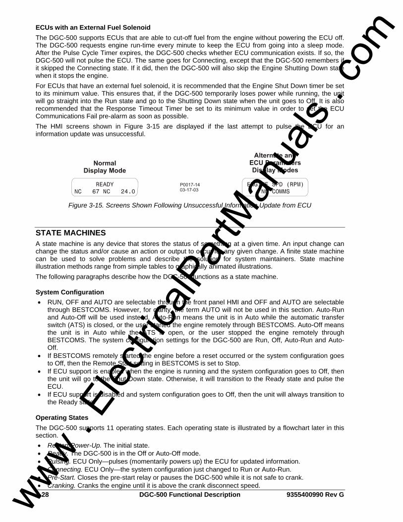
3-28 DGC-500 Functional Description 9355400990 Rev G
ECUs with an External Fuel Solenoid The DGC-500 supports ECUs that are able to cut-off fuel from the engine without powering the ECU off. The DGC-500 requests engine run-time every minute to keep the ECU from going into a sleep mode. After the Pulse Cycle Timer expires, the DGC-500 checks whether ECU communication exists. If so, the DGC-500 will not pulse the ECU. The same goes for Connecting, except that the DGC-500 remembers if it skipped the Connecting state. If it did, then the DGC-500 will also skip the Engine Shutting Down state when it stops the engine. For ECUs that have an external fuel solenoid, it is recommended that the Engine Shut Down timer be set to its minimum value. This ensures that, if the DGC-500 temporarily loses power while running, the unit will go straight into the Run state and go to the Shutting Down state when the unit goes to Off. It is also recommended that the Response Timeout Timer be set to its minimum value in order to set the ECU Communications Fail pre-alarm as soon as possible. The HMI screens shown in Figure 3-15 are displayed if the last attempt to pulse the ECU for an information update was unsuccessful.
Figure 3-15. Screens Shown Following Unsuccessful Information Update from ECU
STATE MACHINES A state machine is any device that stores the status of something at a given time. An input change can change the status and/or cause an action or output to occur for any given change. A finite state machine can be used to solve problems and describe the solution for system maintainers. State machine illustration methods range from simple tables to graphically animated illustrations. The following paragraphs describe how the DGC-500 functions as a state machine.
System Configuration • RUN, OFF and AUTO are selectable through the front panel HMI and OFF and AUTO are selectable
through BESTCOMS. However, for clarity, the term AUTO will not be used in this section. Auto-Run and Auto-Off will be used instead. Auto-Run means the unit is in Auto while the automatic transfer switch (ATS) is closed, or the user started the engine remotely through BESTCOMS. Auto-Off means the unit is in Auto while the ATS is open, or the user stopped the engine remotely through BESTCOMS. The system configuration settings for the DGC-500 are Run, Off, Auto-Run and Auto-Off.
• If BESTCOMS remotely started the engine before a reset occurred or the system configuration goes to Off, then the Remote Start setting in BESTCOMS is set to Stop.
• If ECU support is enabled when the engine is running and the system configuration goes to Off, then the unit will go to the Shut Down state. Otherwise, it will transition to the Ready state and pulse the ECU.
• If ECU support is disabled and system configuration goes to Off, then the unit will always transition to the Ready state.
Operating States The DGC-500 supports 11 operating states. Each operating state is illustrated by a flowchart later in this section. • Restart/Power-Up. The initial state. • Ready. The DGC-500 is in the Off or Auto-Off mode. • Pulsing. ECU Only—pulses (momentarily powers up) the ECU for updated information. • Connecting. ECU Only—the system configuration just changed to Run or Auto-Run. • Pre-Start. Closes the pre-start relay or pauses the DGC-500 while it is not safe to crank. • Cranking. Cranks the engine until it is above the crank disconnect speed. www .
Elec
tricalP
artM
anua
ls . c
om
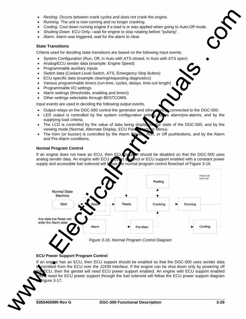
9355400990 Rev G DGC-500 Functional Description 3-29
• Resting. Occurs between crank cycles and does not crank the engine. • Running. The unit is now running and no longer cranking. • Cooling. Cool down running engine if a load is or was applied when going to Auto-Off mode. • Shutting Down. ECU Only—wait for engine to stop rotating before "pulsing". • Alarm. Alarm was triggered, wait for the alarm to clear.
State Transitions Criteria used for deciding state transitions are based on the following input events. • System Configuration (Run, Off, in Auto with ATS closed, in Auto with ATS open) • Analog/ECU sender data (example: Engine Speed) • Programmable auxiliary inputs • Switch data (Coolant Level Switch, ATS, Emergency Stop Button) • ECU-specific data (example clearing/requesting diagnostics) • Various programmable timers (run-time, cycles, delays, time-out length) • Programmable I/O settings • Alarm settings (thresholds, enabling and timers) • Other settings selectable through BESTCOMS.
Input events are used in deciding the following output events. • Output relays on the DGC-500 control the generator and other devices connected to the DGC-500. • LED output is controlled by the system configuration setting, active alarm/pre-alarms, and by the
supplying load criteria. • The LCD is controlled by the value of data being displayed, the state of the DGC-500, and by the
viewing mode (Normal, Alternate Display, ECU Parameters, or Menu). • The horn (or buzzer) is controlled by the Alarm Silence, Run, or Off pushbuttons, and by the Alarm
and Pre-Alarm conditions.
Normal Program Control If an engine does not have an ECU, then ECU Support should be disabled so that the DGC-500 uses analog sender data. An engine with ECU support disabled or ECU support enabled with a constant power supply and accessible fuel solenoid will follow the normal program control flowchart of Figure 3-16.
Figure 3-16. Normal Program Control Diagram
ECU Power Support Program Control If an engine has an ECU, then ECU support should be enabled so that the DGC-500 uses sender data transmitted from the ECU over the J1939 interface. If the engine can be shut down only by powering off the ECU, then the genset will need ECU power support enabled. An engine with ECU support enabled and a need for ECU power support through the fuel solenoid will follow the ECU power support diagram of Figure 3-17.
www . El
ectric
alPar
tMan
uals
. com
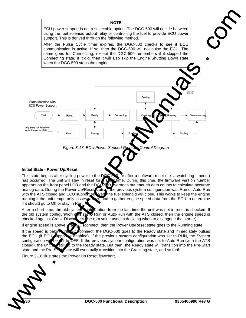
3-30 DGC-500 Functional Description 9355400990 Rev G
Figure 3-17. ECU Power Support Program Control Diagram
Initial State - Power Up/Reset This state begins after cycling power to the DGC-500, or after a software reset (i.e. a watchdog timeout) has occurred. The unit will stay in reset for a short time. During this time, the firmware version number appears on the front panel LCD and the DGC-500 averages out enough data counts to calculate accurate analog data. During the Power Up/Reset state, if the previous system configuration was Run or Auto-Run with the ATS closed and ECU support enabled, the fuel solenoid will close. This works to keep the engine running if the unit temporarily losses power, and to gather engine speed data from the ECU to determine if it should go to Off or stay in Run. After a short time, the old system configuration from the last time the unit was not in reset is checked. If the old system configuration was set to Run or Auto-Run with the ATS closed, then the engine speed is checked against Crank-Disconnect (the rpm value used in deciding when to disengage the starter). If engine speed is above Crank-Disconnect, then the Power Up/Reset state goes to the Running state. If the speed is below Crank-Disconnect, the DGC-500 goes to the Ready state and immediately pulses the ECU (if ECU support is enabled). If the previous system configuration was set to RUN, the System configuration will be set to OFF. If the previous system configuration was set to Auto-Run (with the ATS closed), the unit will still go to the Ready state. But then, the Ready state will transition into the Pre-Start state and the Pre-Start state will eventually transition into the Cranking state, and so forth. Figure 3-18 illustrates the Power Up Reset flowchart.
NOTE ECU power support is not a selectable option. The DGC-500 will decide between using the fuel solenoid output relay or controlling the fuel to provide ECU power support. This is derived through the following method. After the Pulse Cycle timer expires, the DGC-500 checks to see if ECU communication is active. If so, then the DGC-500 will not pulse the ECU. The same goes for Connecting, except the DGC-500 remembers if it skipped the Connecting state. If it did, then it will also skip the Engine Shutting Down state when the DGC-500 stops the engine.
www . El
ectric
alPar
tMan
uals
. com
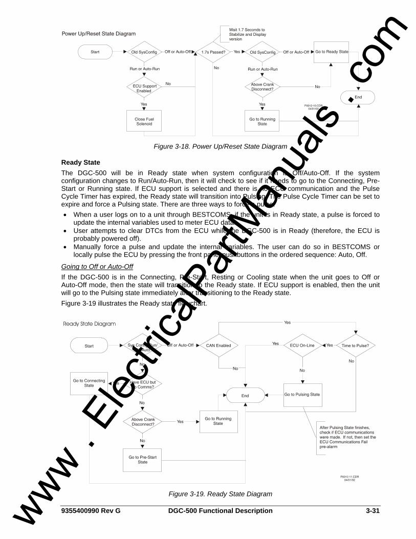
9355400990 Rev G DGC-500 Functional Description 3-31
Figure 3-18. Power Up/Reset State Diagram
Ready State The DGC-500 will be in Ready state when system configuration is Off/Auto-Off. If the system configuration changes to Run/Auto-Run, then it will check to see if it needs to go to the Connecting, Pre-Start or Running state. If ECU support is selected and there is no ECU communication and the Pulse Cycle Timer has expired, the Ready state will transition into Pulsing. The Pulse Cycle Timer can be set to expire and force a Pulsing state. There are three ways to force a pulse. • When a user logs on to a unit through BESTCOMS, if the unit is in Ready state, a pulse is forced to
update the internal variables used to meter ECU data. • User attempts to clear DTCs from the ECU while the DGC-500 is in Ready (therefore, the ECU is
probably powered off). • Manually force a pulse and update the internal variables. The user can do so in BESTCOMS or
locally pulse the ECU by pressing the front panel pushbuttons in the ordered sequence: Auto, Off.
Going to Off or Auto-Off If the DGC-500 is in the Connecting, Pre-Start, Resting or Cooling state when the unit goes to Off or Auto-Off mode, then the state will transition to the Ready state. If ECU support is enabled, then the unit will go to the Pulsing state immediately after transitioning to the Ready state. Figure 3-19 illustrates the Ready state flowchart.
Figure 3-19. Ready State Diagram
www . El
ectric
alPar
tMan
uals
. com
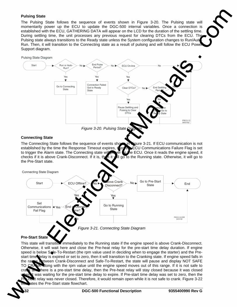
3-32 DGC-500 Functional Description 9355400990 Rev G
Pulsing State The Pulsing State follows the sequence of events shown in Figure 3-20. The Pulsing state will momentarily power up the ECU to update the DGC-500 internal variables. Once a connection is established with the ECU, GATHERING DATA will appear on the LCD for the duration of the settling time. During settling time, the unit processes any previous request for clearing DTCs from the ECU. The Pulsing state always transitions to the Ready state unless the System configuration changes to Run/Auto-Run. Then, it will transition to the Connecting state as a result of pulsing and will follow the ECU Power Support diagram.
Figure 3-20. Pulsing State Diagram
Connecting State The Connecting State follows the sequence of events shown in Figure 3-21. If ECU communication is not established by the time the Response Timeout expires, then the ECU Communications Failure Flag is set to trigger the Alarm state. The Connecting state will power up the ECU. Once it reads the engine speed, it checks if it is above Crank-Disconnect. If it is, then it will go to the Running state. Otherwise, it will go to the Pre-Start state.
Figure 3-21. Connecting State Diagram
Pre-Start State This state will transition immediately to the Running state if the engine speed is above Crank-Disconnect. Otherwise, it will wait here and close the Pre-heat relay for the pre-start time delay duration. If engine speed is below Safe-To-Restart (the rpm value used in deciding when to engage the starter) and the Pre-start time delay is expired or set to zero, then it will transition to the Cranking state. If engine speed falls in the range between Crank-Disconnect and Safe-To-Restart, the state will pause and display NOT SAFE TO CRANK along with the rpm value until the engine speed moves out of this range. If it is not safe to crank and there is a pre-start time delay, then the Pre-heat relay will stay closed because it was closed when it was waiting for the pre-start time delay to expire. If Pre-start time delay was set to zero, then the Pre-heat relay was never closed. Therefore, it would remain open while it is not safe to crank. Figure 3-22 illustrates the Pre-Start state flowchart.
www . El
ectric
alPar
tMan
uals
. com
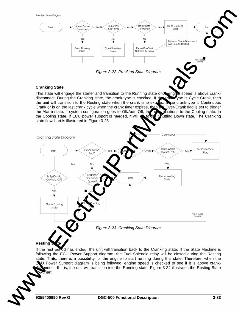
9355400990 Rev G DGC-500 Functional Description 3-33
Figure 3-22. Pre-Start State Diagram
Cranking State This state will engage the starter and transition to the Running state once engine speed is above crank-disconnect. During the Cranking state, the crank-type is checked. If the crank-type is Cycle Crank, then the unit will transition to the Resting state when the crank time expires. If the crank-type is Continuous Crank or is on the last crank cycle when the crank timer expires, then the Over-Crank flag is set to trigger the Alarm state. If system configuration goes to Off/Auto-Off, the unit transitions to the Cooling state. In the Cooling state, if ECU power support is needed, it will go to the Shutting Down state. The Cranking state flowchart is illustrated in Figure 3-23.
Figure 3-23. Cranking State Diagram
Resting State If the rest period has ended, the unit will transition back to the Cranking state. If the State Machine is following the ECU Power Support diagram, the Fuel Solenoid relay will be closed during the Resting state. Thus, there is a possibility for the engine to start running during this state. Therefore, when the ECU Power Support diagram is being followed, engine speed is checked to see if it is above crank-disconnect. If it is, the unit will transition into the Running state. Figure 3-24 illustrates the Resting State flowchart.
www . El
ectric
alPar
tMan
uals
. com
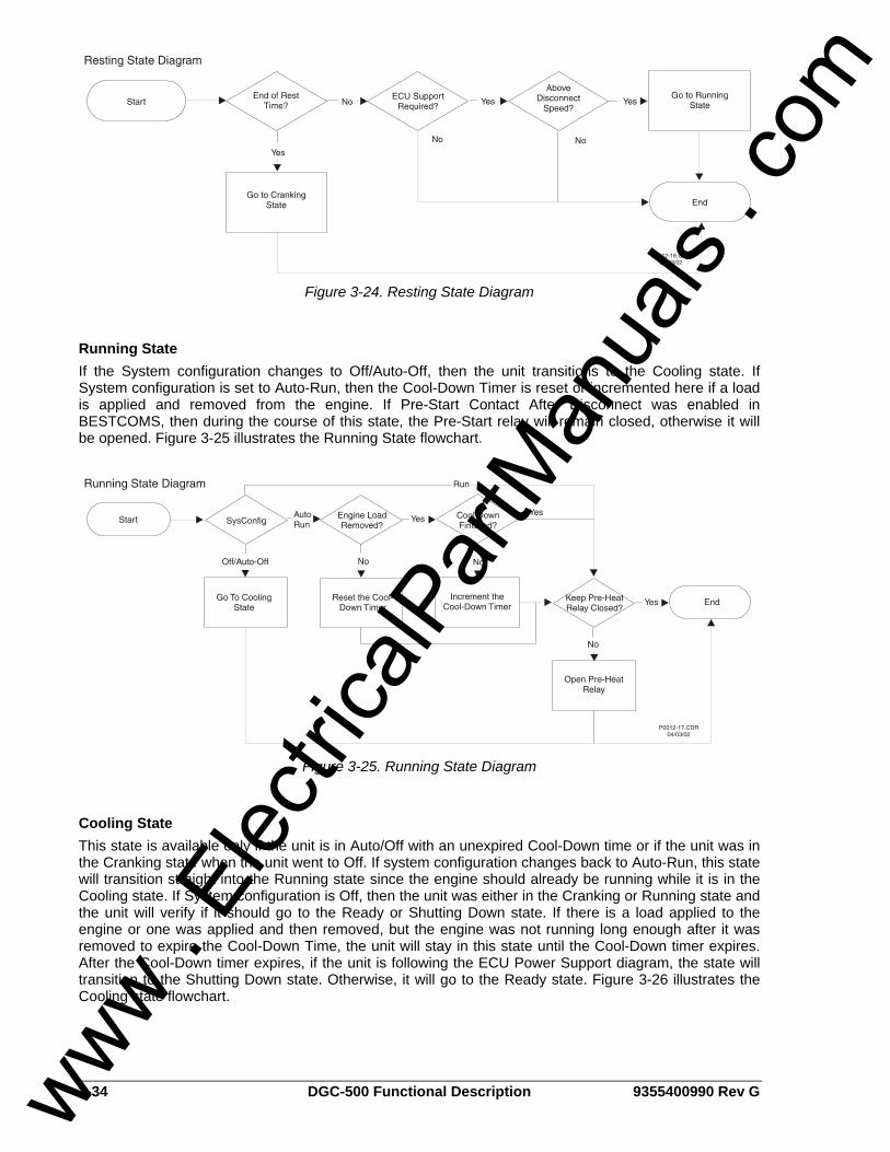
3-34 DGC-500 Functional Description 9355400990 Rev G
Figure 3-24. Resting State Diagram
Running State If the System configuration changes to Off/Auto-Off, then the unit transitions to the Cooling state. If System configuration is set to Auto-Run, then the Cool-Down Timer is reset or incremented here if a load is applied and removed from the engine. If Pre-Start Contact After Disconnect was enabled in BESTCOMS, then during the course of this state, the Pre-Start relay will remain closed, otherwise it will be opened. Figure 3-25 illustrates the Running State flowchart.
Figure 3-25. Running State Diagram
Cooling State This state is available only if the unit is in Auto/Off with an unexpired Cool-Down time or if the unit was in the Cranking state when the unit went to Off. If system configuration changes back to Auto-Run, this state will transition straight into the Running state since the engine should already be running while it is in the Cooling state. If System configuration is Off, then the unit was either in the Cranking or Running state and the unit will verify if it should go to the Ready or Shutting Down state. If there is a load applied to the engine or one was applied and then removed, but the engine was not running long enough after it was removed to expire the Cool-Down Time, the unit will stay in this state until the Cool-Down timer expires. After the Cool-Down timer expires, if the unit is following the ECU Power Support diagram, the state will transition to the Shutting Down state. Otherwise, it will go to the Ready state. Figure 3-26 illustrates the Cooling state flowchart.
www . El
ectric
alPar
tMan
uals
. com
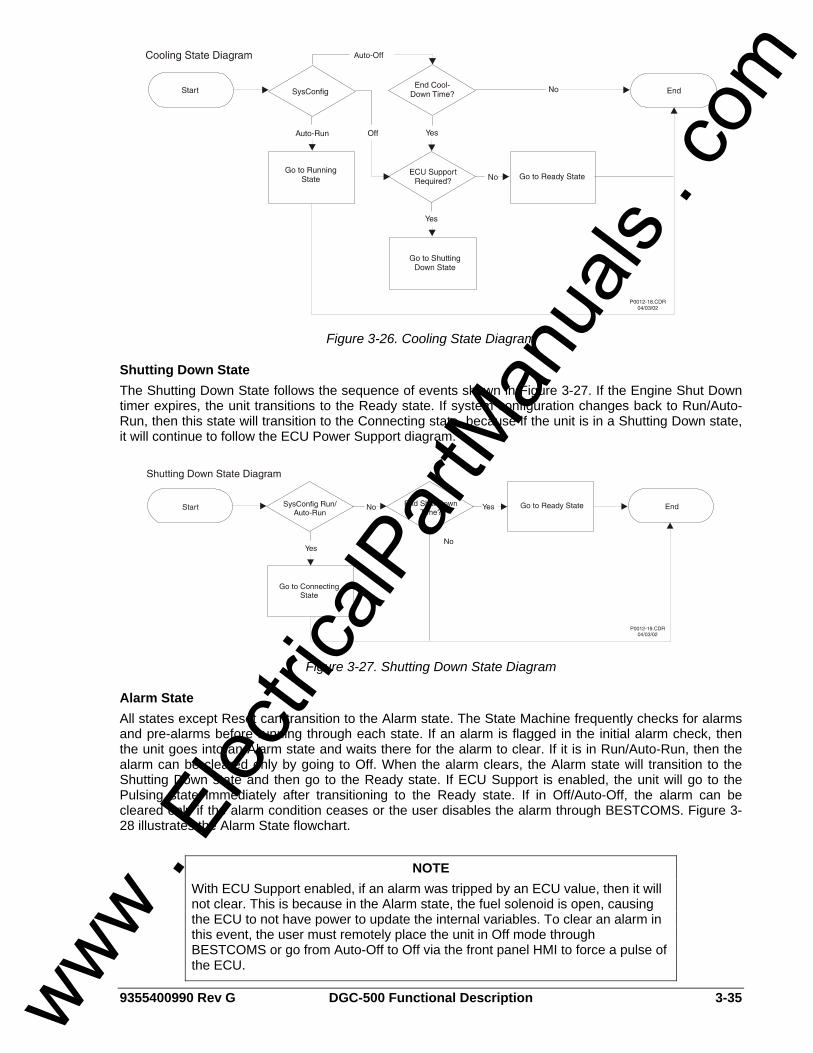
9355400990 Rev G DGC-500 Functional Description 3-35
Figure 3-26. Cooling State Diagram
Shutting Down State The Shutting Down State follows the sequence of events shown in Figure 3-27. If the Engine Shut Down timer expires, the unit transitions to the Ready state. If system configuration changes back to Run/Auto-Run, then this state will transition to the Connecting state, because if the unit is in a Shutting Down state, it will continue to follow the ECU Power Support diagram.
Figure 3-27. Shutting Down State Diagram
Alarm State All states except Reset can transition to the Alarm state. The State Machine frequently checks for alarms and pre-alarms before running through each state. If an alarm is flagged in the initial alarm check, then the unit goes into an Alarm state and waits there for the alarm to clear. If it is in Run/Auto-Run, then the alarm can be cleared only by going to Off. When the alarm clears, the Alarm state will transition to the Shutting Down state and then go to the Ready state. If ECU Support is enabled, the unit will go to the Pulsing state immediately after transitioning to the Ready state. If in Off/Auto-Off, the alarm can be cleared only if the alarm condition ceases or the user disables the alarm through BESTCOMS. Figure 3-28 illustrates the Alarm State flowchart.
NOTE With ECU Support enabled, if an alarm was tripped by an ECU value, then it will not clear. This is because in the Alarm state, the fuel solenoid is open, causing the ECU to not have power to update the internal variables. To clear an alarm in this event, the user must remotely place the unit in Off mode through BESTCOMS or go from Auto-Off to Off via the front panel HMI to force a pulse of the ECU.
www . El
ectric
alPar
tMan
uals
. com
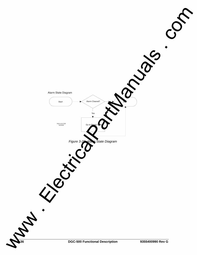
3-36 DGC-500 Functional Description 9355400990 Rev G
Figure 3-28. Alarm State Diagram
www . El
ectric
alPar
tMan
uals
. com
9355400990 Rev G DGC-500 BESTCOMS Software i
SECTION 4 • BESTCOMS SOFTWARE TABLE OF CONTENTS
SECTION 4 • BESTCOMS SOFTWARE .................................................................................................. 4-1
INTRODUCTION.................................................................................................................................... 4-1 INSTALLATION...................................................................................................................................... 4-1
Installing DGC-500 BESTCOMS........................................................................................................ 4-1 Connecting the DGC-500 and PC...................................................................................................... 4-1
STARTING BESTCOMS........................................................................................................................ 4-1 Establishing Communication .............................................................................................................. 4-1 Establishing Communication .............................................................................................................. 4-2
CHANGING SETTINGS......................................................................................................................... 4-2 SENDING AND RECEIVING SETTINGS .............................................................................................. 4-3
Sending Settings ................................................................................................................................ 4-3 Receiving Settings.............................................................................................................................. 4-3
SETTING DEFINITIONS........................................................................................................................ 4-3 Sensing Transformers ........................................................................................................................ 4-3 Pre-Alarms.......................................................................................................................................... 4-4 Alarms ................................................................................................................................................ 4-7 Engine Cranking................................................................................................................................. 4-9 System.............................................................................................................................................. 4-10 Programmable Inputs and Outputs .................................................................................................. 4-12 Generator Protection ........................................................................................................................ 4-14
REAL-TIME CLOCK ............................................................................................................................ 4-19 PROGRAMMABLE SENDERS............................................................................................................ 4-19
Fuel Level Type................................................................................................................................ 4-20 RUN STATISTICS ............................................................................................................................... 4-20 event log............................................................................................................................................... 4-21 SETTINGS FILES ................................................................................................................................ 4-22
Printing Settings Files....................................................................................................................... 4-22 New Settings File ............................................................................................................................. 4-22 Saving Settings Files........................................................................................................................ 4-22 Opening Settings Files ..................................................................................................................... 4-23
RS-232 CONFIGURATION.................................................................................................................. 4-23 ENGINE CONTROL UNIT (ECU) INTERFACE................................................................................... 4-23 PASSWORD PROTECTION ............................................................................................................... 4-24
Changing Passwords ....................................................................................................................... 4-24 TERMINATING COMMUNICATION.................................................................................................... 4-24 EMBEDDED FIRMWARE.................................................................................................................... 4-25
Updating the Firmware ..................................................................................................................... 4-25
Figures Figure 4-1. Basler Electric Folder Contents .............................................................................................. 4-1 Figure 4-5. Sensing Transformers Screen ................................................................................................ 4-3 Figure 4-6. Pre-Alarm Screen, Low Fuel-Low Cool-Batt. OverVolt Tab.................................................... 4-4 Figure 4-7. Pre-Alarm Screen, Low Oil-Low Batt Volt-Weak Batt Volt Tab............................................... 4-5 Figure 4-8. Pre-Alarms Screen, Audible-Fuel Level Sender Tab.............................................................. 4-6 Figure 4-9. Pre-Alarms Screen, Maint. Interv.-Hi Cool Tab ...................................................................... 4-6 Figure 4-10. Pre-Alarms Screen, CAN Bus-Diagnostic Trouble Codes.................................................... 4-7 Figure 4-11. Alarms Screen, Hi Cool-Low Fuel-Low Oil Tab .................................................................... 4-8 Figure 4-12. Alarms Screen, Overspeed-Sender Fail Tab........................................................................ 4-9 Figure 4-13. Engine Cranking Screen ..................................................................................................... 4-10 Figure 4-14. System Setting Screen........................................................................................................ 4-11 Figure 4-15. Settings Screen, Input Setup Tab ....................................................................................... 4-13 Figure 4-16. Settings Screen, Output Setup Tab .................................................................................... 4-13 Figure 4-17. Generator Protection Screen, 51 Tab................................................................................. 4-14 Figure 4-18. Generator Protection Screen, 47 Tab................................................................................. 4-16 Figure 4-19. Generator Protection Scree, 27 Tab................................................................................... 4-16 www .
Elec
tricalP
artM
anua
ls . c
om
ii DGC-500 BESTCOMS Software 9355400990 Rev G
Figure 4-20. Generator Protection Screen, 59 Tab ................................................................................. 4-17 Figure 4-21. Generator Protection Screen, 81 Tab ................................................................................. 4-18 Figure 4-23. Programmable Senders Screen, Coolant Temperature Tab .............................................. 4-20 Figure 4-24. Run Statistics Screen.......................................................................................................... 4-21 Figure 4-25. Event Log Screen................................................................................................................ 4-22 Figure 4-29. Embedded Firmware Upgrade Dialog Box ......................................................................... 4-25 Figure 4-30. Firmware File Information ................................................................................................... 4-26 Figure 4-31. File Transfer Status............................................................................................................. 4-26
www . El
ectric
alPar
tMan
uals
. com
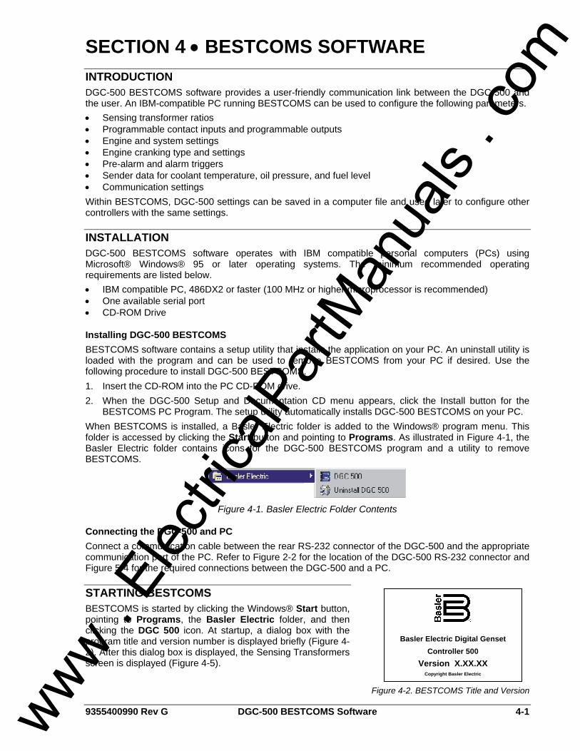
9355400990 Rev G DGC-500 BESTCOMS Software 4-1
SECTION 4 • BESTCOMS SOFTWARE INTRODUCTION DGC-500 BESTCOMS software provides a user-friendly communication link between the DGC-500 and the user. An IBM-compatible PC running BESTCOMS can be used to configure the following parameters. • Sensing transformer ratios • Programmable contact inputs and programmable outputs • Engine and system settings • Engine cranking type and settings • Pre-alarm and alarm triggers • Sender data for coolant temperature, oil pressure, and fuel level • Communication settings Within BESTCOMS, DGC-500 settings can be saved in a computer file and used later to configure other controllers with the same settings.
INSTALLATION DGC-500 BESTCOMS software operates with IBM compatible personal computers (PCs) using Microsoft® Windows® 95 or later operating systems. The minimum recommended operating requirements are listed below. • IBM compatible PC, 486DX2 or faster (100 MHz or higher microprocessor is recommended) • One available serial port • CD-ROM Drive
Installing DGC-500 BESTCOMS BESTCOMS software contains a setup utility that installs the application on your PC. An uninstall utility is loaded with the program and can be used to remove BESTCOMS from your PC if desired. Use the following procedure to install DGC-500 BESTCOMS. 1. Insert the CD-ROM into the PC CD-ROM drive. 2. When the DGC-500 Setup and Documentation CD menu appears, click the Install button for the
BESTCOMS PC Program. The setup utility automatically installs DGC-500 BESTCOMS on your PC. When BESTCOMS is installed, a Basler Electric folder is added to the Windows® program menu. This folder is accessed by clicking the Start button and pointing to Programs. As illustrated in Figure 4-1, the Basler Electric folder contains icons for the DGC-500 BESTCOMS program and a utility to remove BESTCOMS.
Figure 4-1. Basler Electric Folder Contents
Connecting the DGC-500 and PC Connect a communication cable between the rear RS-232 connector of the DGC-500 and the appropriate communication port of the PC. Refer to Figure 2-2 for the location of the DGC-500 RS-232 connector and Figure 5-4 for the required connections between the DGC-500 and a PC.
STARTING BESTCOMS BESTCOMS is started by clicking the Windows® Start button, pointing to Programs, the Basler Electric folder, and then clicking the DGC 500 icon. At startup, a dialog box with the program title and version number is displayed briefly (Figure 4-2). After this dialog box is displayed, the Sensing Transformers screen is displayed (Figure 4-5).
Basler Electric Digital Genset Controller 500
Version X.XX.XX Copyright Basler Electric
Figure 4-2. BESTCOMS Title and Version
www . El
ectric
alPar
tMan
uals
. com
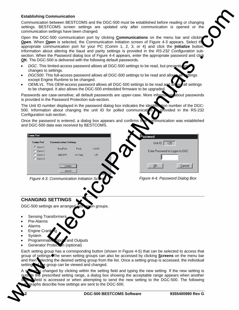
4-2 DGC-500 BESTCOMS Software 9355400990 Rev G
Establishing Communication Communication between BESTCOMS and the DGC-500 must be established before reading or changing settings. BESTCOMS screen settings are updated only after communication is opened or the communication settings have been changed. Open the DGC-500 communication port by clicking Communications on the menu bar and clicking Open. When Open is selected, the Communication Initiation screen of Figure 4-3 appears. Select the appropriate communication port for your PC (Comm 1, 2, 3, or 4) and click the Initialize button. Information about altering the baud and parity settings is provided in the RS-232 Configuration sub-section. When the Password dialog box of Figure 4-4 appears, enter the appropriate password and click OK. The DGC-500 is delivered with the following default passwords. • DGC. This limited-access password allows all DGC-500 settings to be read, but prevents any
changes to settings. • DGC500. This full-access password allows all DGC-500 settings to be read and allows all settings
except Engine Runtime to be changed. • OEMLVL. This OEM-access password allows all DGC-500 settings to be read and allows all settings
to be changed. It also allows the DGC-500 embedded firmware to be upgraded. Passwords are case-sensitive; all default passwords are upper-case. More information about passwords is provided in the Password Protection sub-section. The Unit ID number displayed in the password dialog box indicates the identification number of the DGC-500. Information about changing the unit ID for polled communication is provided in the RS-232 Configuration sub-section. Once the password is entered, a dialog box appears and confirms that communication was established and DGC-500 data was received by BESTCOMS.
CHANGING SETTINGS DGC-500 settings are arranged into seven groups. • Sensing Transformers • Pre-Alarms • Alarms • Engine Cranking • System • Programmable Inputs and Outputs • Generator Protection (optional) Each setting group has a corresponding button (shown in Figure 4-5) that can be selected to access that group of settings. The seven setting groups can also be accessed by clicking Screens on the menu bar and then selecting the desired setting group from the list. Once a setting group is accessed, the individual settings of the group can be viewed and changed. A setting is changed by clicking within the setting field and typing the new setting. If the new setting is outside the prescribed setting range, a dialog box showing the acceptable range appears when another setting field is accessed or when attempting to send the new setting to the DGC-500. The following paragraphs describe how settings are sent to the DGC-500.
Figure 4-3. Communication Initiation Screen Figure 4-4. Password Dialog Box
www . El
ectric
alPar
tMan
uals
. com
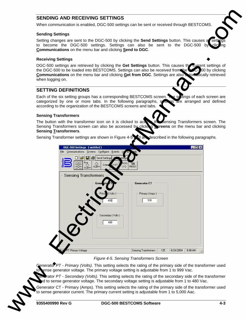
9355400990 Rev G DGC-500 BESTCOMS Software 4-3
SENDING AND RECEIVING SETTINGS When communication is enabled, DGC-500 settings can be sent or received through BESTCOMS.
Sending Settings Setting changes are sent to the DGC-500 by clicking the Send Settings button. This causes all settings to become the DGC-500 settings. Settings can also be sent to the DGC-500 by clicking Communications on the menu bar and clicking Send to DGC.
Receiving Settings DGC-500 settings are retrieved by clicking the Get Settings button. This causes the current settings of the DGC-500 to be loaded into BESTCOMS. Settings can also be received from the DGC-500 by clicking Communications on the menu bar and clicking Get from DGC. Settings are also automatically retrieved when logging on.
SETTING DEFINITIONS Each of the six setting groups has a corresponding BESTCOMS screen. The settings of each screen are categorized by one or more tabs. In the following paragraphs, settings are arranged and defined according to the organization of the BESTCOMS screens and tabs.
Sensing Transformers The button with the transformer icon on it is clicked to access the Sensing Transformers screen. The Sensing Transformers screen can also be accessed by clicking Screens on the menu bar and clicking Sensing Transformers. Sensing Transformer settings are shown in Figure 4-5 and are described in the following paragraphs.
Figure 4-5. Sensing Transformers Screen
Generator PT - Primary (Volts). This setting selects the rating of the primary side of the transformer used to sense generator voltage. The primary voltage setting is adjustable from 1 to 999 Vac. Generator PT - Secondary (Volts). This setting selects the rating of the secondary side of the transformer used to sense generator voltage. The secondary voltage setting is adjustable from 1 to 480 Vac. Generator CT - Primary (Amps). This setting selects the rating of the primary side of the transformer used to sense generator current. The primary current setting is adjustable from 1 to 5,000 Aac.
www . El
ectric
alPar
tMan
uals
. com
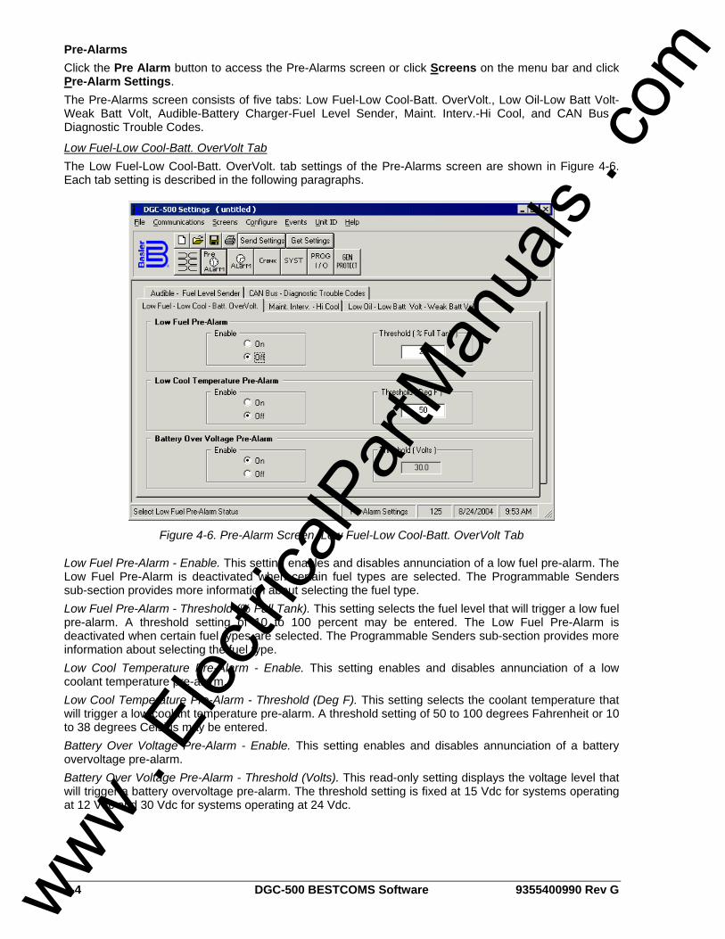
4-4 DGC-500 BESTCOMS Software 9355400990 Rev G
Pre-Alarms Click the Pre Alarm button to access the Pre-Alarms screen or click Screens on the menu bar and click Pre-Alarm Settings. The Pre-Alarms screen consists of five tabs: Low Fuel-Low Cool-Batt. OverVolt., Low Oil-Low Batt Volt-Weak Batt Volt, Audible-Battery Charger-Fuel Level Sender, Maint. Interv.-Hi Cool, and CAN Bus - Diagnostic Trouble Codes.
Low Fuel-Low Cool-Batt. OverVolt Tab The Low Fuel-Low Cool-Batt. OverVolt. tab settings of the Pre-Alarms screen are shown in Figure 4-6. Each tab setting is described in the following paragraphs.
Figure 4-6. Pre-Alarm Screen, Low Fuel-Low Cool-Batt. OverVolt Tab
Low Fuel Pre-Alarm - Enable. This setting enables and disables annunciation of a low fuel pre-alarm. The Low Fuel Pre-Alarm is deactivated when certain fuel types are selected. The Programmable Senders sub-section provides more information about selecting the fuel type. Low Fuel Pre-Alarm - Threshold (% Full Tank). This setting selects the fuel level that will trigger a low fuel pre-alarm. A threshold setting of 10 to 100 percent may be entered. The Low Fuel Pre-Alarm is deactivated when certain fuel types are selected. The Programmable Senders sub-section provides more information about selecting the fuel type. Low Cool Temperature Pre-Alarm - Enable. This setting enables and disables annunciation of a low coolant temperature pre-alarm. Low Cool Temperature Pre-Alarm - Threshold (Deg F). This setting selects the coolant temperature that will trigger a low coolant temperature pre-alarm. A threshold setting of 50 to 100 degrees Fahrenheit or 10 to 38 degrees Celsius may be entered. Battery Over Voltage Pre-Alarm - Enable. This setting enables and disables annunciation of a battery overvoltage pre-alarm. Battery Over Voltage Pre-Alarm - Threshold (Volts). This read-only setting displays the voltage level that will trigger a battery overvoltage pre-alarm. The threshold setting is fixed at 15 Vdc for systems operating at 12 Vdc and 30 Vdc for systems operating at 24 Vdc.
www . El
ectric
alPar
tMan
uals
. com
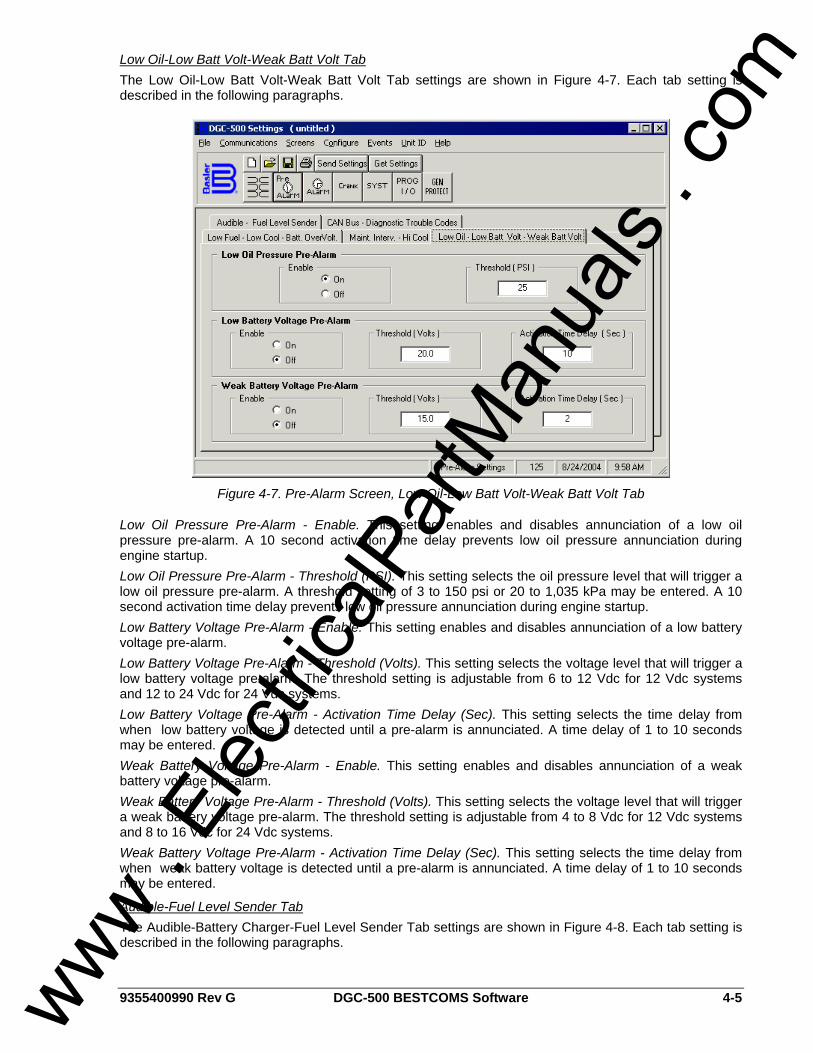
9355400990 Rev G DGC-500 BESTCOMS Software 4-5
Low Oil-Low Batt Volt-Weak Batt Volt Tab The Low Oil-Low Batt Volt-Weak Batt Volt Tab settings are shown in Figure 4-7. Each tab setting is described in the following paragraphs.
Figure 4-7. Pre-Alarm Screen, Low Oil-Low Batt Volt-Weak Batt Volt Tab
Low Oil Pressure Pre-Alarm - Enable. This setting enables and disables annunciation of a low oil pressure pre-alarm. A 10 second activation time delay prevents low oil pressure annunciation during engine startup. Low Oil Pressure Pre-Alarm - Threshold (PSI). This setting selects the oil pressure level that will trigger a low oil pressure pre-alarm. A threshold setting of 3 to 150 psi or 20 to 1,035 kPa may be entered. A 10 second activation time delay prevents low oil pressure annunciation during engine startup. Low Battery Voltage Pre-Alarm - Enable. This setting enables and disables annunciation of a low battery voltage pre-alarm. Low Battery Voltage Pre-Alarm - Threshold (Volts). This setting selects the voltage level that will trigger a low battery voltage pre-alarm. The threshold setting is adjustable from 6 to 12 Vdc for 12 Vdc systems and 12 to 24 Vdc for 24 Vdc systems. Low Battery Voltage Pre-Alarm - Activation Time Delay (Sec). This setting selects the time delay from when low battery voltage is detected until a pre-alarm is annunciated. A time delay of 1 to 10 seconds may be entered. Weak Battery Voltage Pre-Alarm - Enable. This setting enables and disables annunciation of a weak battery voltage pre-alarm. Weak Battery Voltage Pre-Alarm - Threshold (Volts). This setting selects the voltage level that will trigger a weak battery voltage pre-alarm. The threshold setting is adjustable from 4 to 8 Vdc for 12 Vdc systems and 8 to 16 Vdc for 24 Vdc systems. Weak Battery Voltage Pre-Alarm - Activation Time Delay (Sec). This setting selects the time delay from when weak battery voltage is detected until a pre-alarm is annunciated. A time delay of 1 to 10 seconds may be entered.
Audible-Fuel Level Sender Tab The Audible-Battery Charger-Fuel Level Sender Tab settings are shown in Figure 4-8. Each tab setting is described in the following paragraphs.
www . El
ectric
alPar
tMan
uals
. com
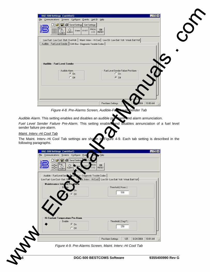
4-6 DGC-500 BESTCOMS Software 9355400990 Rev G
Figure 4-8. Pre-Alarms Screen, Audible-Fuel Level Sender Tab
Audible Alarm. This setting enables and disables an audible pre-alarm and alarm annunciation. Fuel Level Sender Failure Pre-Alarm. This setting enables and disables annunciation of a fuel level sender failure pre-alarm.
Maint. Interv.-Hi Cool Tab The Maint. Interv.-Hi Cool Tab settings are shown in Figure 4-9. Each tab setting is described in the following paragraphs.
Figure 4-9. Pre-Alarms Screen, Maint. Interv.-Hi Cool Tab
www . El
ectric
alPar
tMan
uals
. com
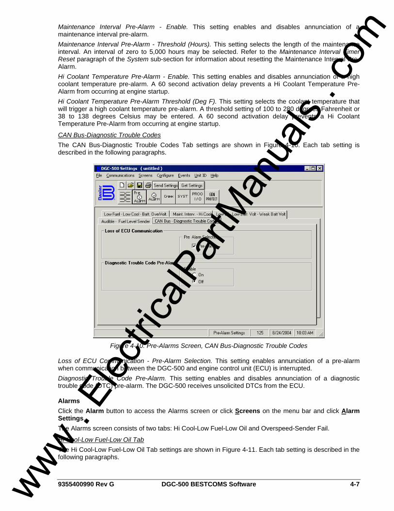
9355400990 Rev G DGC-500 BESTCOMS Software 4-7
Maintenance Interval Pre-Alarm - Enable. This setting enables and disables annunciation of a maintenance interval pre-alarm. Maintenance Interval Pre-Alarm - Threshold (Hours). This setting selects the length of the maintenance interval. An interval of zero to 5,000 hours may be selected. Refer to the Maintenance Interval Timer Reset paragraph of the System sub-section for information about resetting the Maintenance Interval Pre-Alarm. Hi Coolant Temperature Pre-Alarm - Enable. This setting enables and disables annunciation of a high coolant temperature pre-alarm. A 60 second activation delay prevents a Hi Coolant Temperature Pre-Alarm from occurring at engine startup. Hi Coolant Temperature Pre-Alarm Threshold (Deg F). This setting selects the coolant temperature that will trigger a high coolant temperature pre-alarm. A threshold setting of 100 to 280 degrees Fahrenheit or 38 to 138 degrees Celsius may be entered. A 60 second activation delay prevents a Hi Coolant Temperature Pre-Alarm from occurring at engine startup.
CAN Bus-Diagnostic Trouble Codes The CAN Bus-Diagnostic Trouble Codes Tab settings are shown in Figure 4-10. Each tab setting is described in the following paragraphs.
Figure 4-10. Pre-Alarms Screen, CAN Bus-Diagnostic Trouble Codes
Loss of ECU Communication - Pre-Alarm Selection. This setting enables annunciation of a pre-alarm when communication between the DGC-500 and engine control unit (ECU) is interrupted. Diagnostic Trouble Code Pre-Alarm. This setting enables and disables annunciation of a diagnostic trouble code (DTC) pre-alarm. The DGC-500 receives unsolicited DTCs from the ECU.
Alarms Click the Alarm button to access the Alarms screen or click Screens on the menu bar and click Alarm Settings. The Alarms screen consists of two tabs: Hi Cool-Low Fuel-Low Oil and Overspeed-Sender Fail.
Hi Cool-Low Fuel-Low Oil Tab The Hi Cool-Low Fuel-Low Oil Tab settings are shown in Figure 4-11. Each tab setting is described in the following paragraphs.
www . El
ectric
alPar
tMan
uals
. com
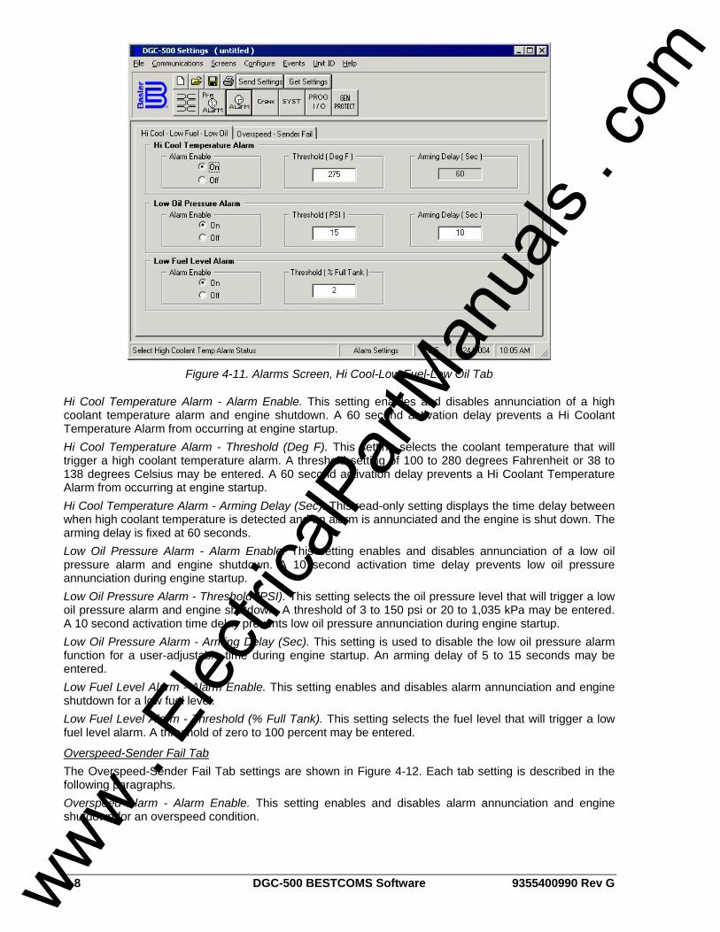
4-8 DGC-500 BESTCOMS Software 9355400990 Rev G
Figure 4-11. Alarms Screen, Hi Cool-Low Fuel-Low Oil Tab
Hi Cool Temperature Alarm - Alarm Enable. This setting enables and disables annunciation of a high coolant temperature alarm and engine shutdown. A 60 second activation delay prevents a Hi Coolant Temperature Alarm from occurring at engine startup. Hi Cool Temperature Alarm - Threshold (Deg F). This setting selects the coolant temperature that will trigger a high coolant temperature alarm. A threshold setting of 100 to 280 degrees Fahrenheit or 38 to 138 degrees Celsius may be entered. A 60 second activation delay prevents a Hi Coolant Temperature Alarm from occurring at engine startup. Hi Cool Temperature Alarm - Arming Delay (Sec). This read-only setting displays the time delay between when high coolant temperature is detected and an alarm is annunciated and the engine is shut down. The arming delay is fixed at 60 seconds. Low Oil Pressure Alarm - Alarm Enable. This setting enables and disables annunciation of a low oil pressure alarm and engine shutdown. A 10 second activation time delay prevents low oil pressure annunciation during engine startup. Low Oil Pressure Alarm - Threshold (PSI). This setting selects the oil pressure level that will trigger a low oil pressure alarm and engine shutdown. A threshold of 3 to 150 psi or 20 to 1,035 kPa may be entered. A 10 second activation time delay prevents low oil pressure annunciation during engine startup. Low Oil Pressure Alarm - Arming Delay (Sec). This setting is used to disable the low oil pressure alarm function for a user-adjustable time during engine startup. An arming delay of 5 to 15 seconds may be entered. Low Fuel Level Alarm - Alarm Enable. This setting enables and disables alarm annunciation and engine shutdown for a low fuel level. Low Fuel Level Alarm - Threshold (% Full Tank). This setting selects the fuel level that will trigger a low fuel level alarm. A threshold of zero to 100 percent may be entered.
Overspeed-Sender Fail Tab The Overspeed-Sender Fail Tab settings are shown in Figure 4-12. Each tab setting is described in the following paragraphs. Overspeed Alarm - Alarm Enable. This setting enables and disables alarm annunciation and engine shutdown for an overspeed condition.
www . El
ectric
alPar
tMan
uals
. com
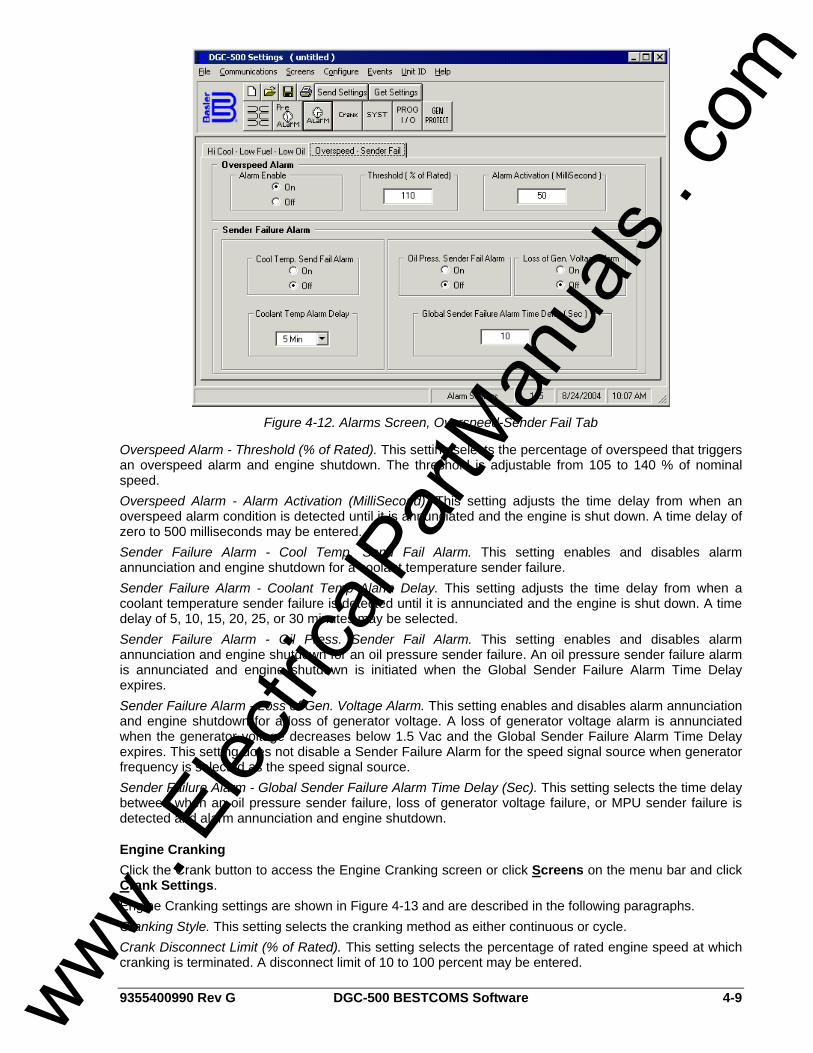
9355400990 Rev G DGC-500 BESTCOMS Software 4-9
Figure 4-12. Alarms Screen, Overspeed-Sender Fail Tab
Overspeed Alarm - Threshold (% of Rated). This setting selects the percentage of overspeed that triggers an overspeed alarm and engine shutdown. The threshold is adjustable from 105 to 140 % of nominal speed. Overspeed Alarm - Alarm Activation (MilliSecond). This setting adjusts the time delay from when an overspeed alarm condition is detected until it is annunciated and the engine is shut down. A time delay of zero to 500 milliseconds may be entered. Sender Failure Alarm - Cool Temp. Send Fail Alarm. This setting enables and disables alarm annunciation and engine shutdown for a coolant temperature sender failure. Sender Failure Alarm - Coolant Temp Alarm Delay. This setting adjusts the time delay from when a coolant temperature sender failure is detected until it is annunciated and the engine is shut down. A time delay of 5, 10, 15, 20, 25, or 30 minutes may be selected. Sender Failure Alarm - Oil Press. Sender Fail Alarm. This setting enables and disables alarm annunciation and engine shutdown for an oil pressure sender failure. An oil pressure sender failure alarm is annunciated and engine shutdown is initiated when the Global Sender Failure Alarm Time Delay expires. Sender Failure Alarm - Loss of Gen. Voltage Alarm. This setting enables and disables alarm annunciation and engine shutdown for a loss of generator voltage. A loss of generator voltage alarm is annunciated when the generator voltage decreases below 1.5 Vac and the Global Sender Failure Alarm Time Delay expires. This setting does not disable a Sender Failure Alarm for the speed signal source when generator frequency is selected as the speed signal source. Sender Failure Alarm - Global Sender Failure Alarm Time Delay (Sec). This setting selects the time delay between when an oil pressure sender failure, loss of generator voltage failure, or MPU sender failure is detected and alarm annunciation and engine shutdown.
Engine Cranking Click the Crank button to access the Engine Cranking screen or click Screens on the menu bar and click Crank Settings. Engine Cranking settings are shown in Figure 4-13 and are described in the following paragraphs. Cranking Style. This setting selects the cranking method as either continuous or cycle. Crank Disconnect Limit (% of Rated). This setting selects the percentage of rated engine speed at which cranking is terminated. A disconnect limit of 10 to 100 percent may be entered.
www . El
ectric
alPar
tMan
uals
. com
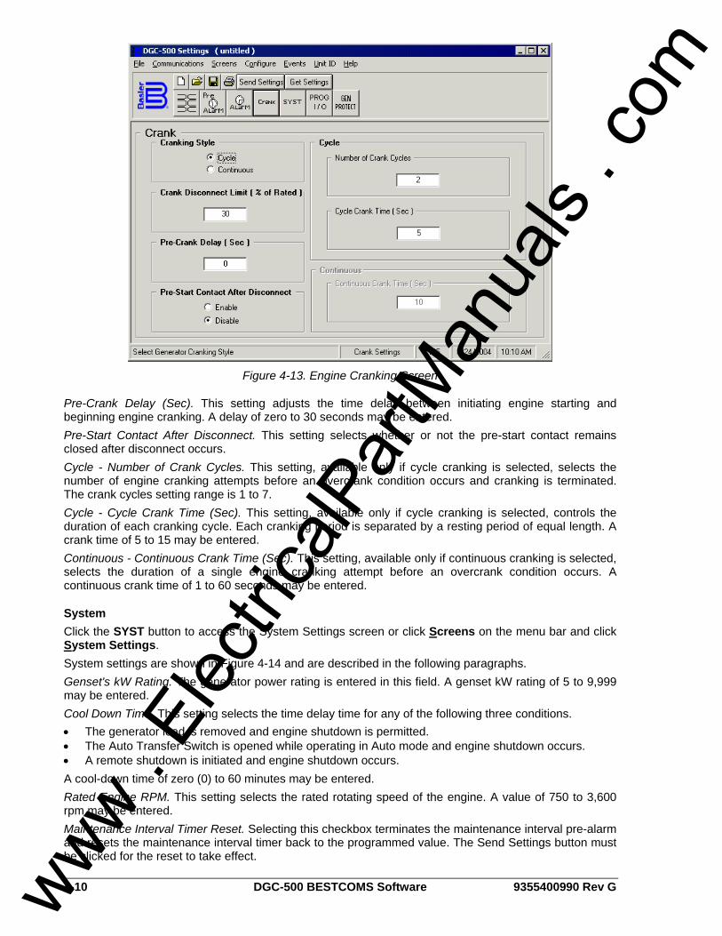
4-10 DGC-500 BESTCOMS Software 9355400990 Rev G
Figure 4-13. Engine Cranking Screen
Pre-Crank Delay (Sec). This setting adjusts the time delay between initiating engine starting and beginning engine cranking. A delay of zero to 30 seconds may be entered. Pre-Start Contact After Disconnect. This setting selects whether or not the pre-start contact remains closed after disconnect occurs. Cycle - Number of Crank Cycles. This setting, available only if cycle cranking is selected, selects the number of engine cranking attempts before an overcrank condition occurs and cranking is terminated. The crank cycles setting range is 1 to 7. Cycle - Cycle Crank Time (Sec). This setting, available only if cycle cranking is selected, controls the duration of each cranking cycle. Each cranking period is separated by a resting period of equal length. A crank time of 5 to 15 may be entered. Continuous - Continuous Crank Time (Sec). This setting, available only if continuous cranking is selected, selects the duration of a single engine cranking attempt before an overcrank condition occurs. A continuous crank time of 1 to 60 seconds may be entered.
System Click the SYST button to access the System Settings screen or click Screens on the menu bar and click System Settings. System settings are shown in Figure 4-14 and are described in the following paragraphs. Genset's kW Rating. The generator power rating is entered in this field. A genset kW rating of 5 to 9,999 may be entered. Cool Down Time. This setting selects the time delay time for any of the following three conditions. • The generator load is removed and engine shutdown is permitted. • The Auto Transfer Switch is opened while operating in Auto mode and engine shutdown occurs. • A remote shutdown is initiated and engine shutdown occurs. A cool-down time of zero (0) to 60 minutes may be entered. Rated Engine RPM. This setting selects the rated rotating speed of the engine. A value of 750 to 3,600 rpm may be entered. Maintenance Interval Timer Reset. Selecting this checkbox terminates the maintenance interval pre-alarm and resets the maintenance interval timer back to the programmed value. The Send Settings button must be clicked for the reset to take effect.
www . El
ectric
alPar
tMan
uals
. com
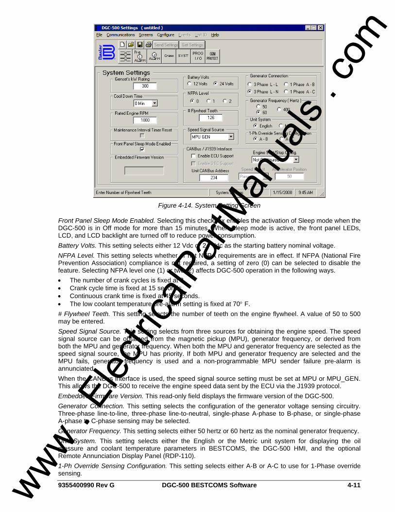
9355400990 Rev G DGC-500 BESTCOMS Software 4-11
Figure 4-14. System Setting Screen
Front Panel Sleep Mode Enabled. Selecting this checkbox enables the activation of Sleep mode when the DGC-500 is in Off mode for more than 15 minutes. When Sleep mode is active, the front panel LEDs, LCD, and LCD backlight are turned off to reduce power consumption. Battery Volts. This setting selects either 12 Vdc or 24 Vdc as the starting battery nominal voltage. NFPA Level. This setting selects whether or not NFPA requirements are in effect. If NFPA (National Fire Prevention Association) compliance is not required, a setting of zero (0) can be selected to disable the feature. Selecting NFPA level one (1) or two (2) affects DGC-500 operation in the following ways. • The number of crank cycles is fixed at 3. • Crank cycle time is fixed at 15 seconds. • Continuous crank time is fixed at 45 seconds. • The low coolant temperature pre-alarm setting is fixed at 70° F. # Flywheel Teeth. This setting selects the number of teeth on the engine flywheel. A value of 50 to 500 may be entered. Speed Signal Source. This setting selects from three sources for obtaining the engine speed. The speed signal source can be obtained from the magnetic pickup (MPU), generator frequency, or derived from both the MPU and generator frequency. When both the MPU and generator frequency are selected as the speed signal source, the MPU has priority. If both MPU and generator frequency are selected and the MPU fails, generator frequency is used and a non-programmable MPU sender failure pre-alarm is annunciated. When the CANBus interface is used, the speed signal source setting must be set at MPU or MPU_GEN. This allows the DGC-500 to receive the engine speed data sent by the ECU via the J1939 protocol. Embedded Firmware Version. This read-only field displays the firmware version of the DGC-500. Generator Connection. This setting selects the configuration of the generator voltage sensing circuitry. Three-phase line-to-line, three-phase line-to-neutral, single-phase A-phase to B-phase, or single-phase A-phase to C-phase sensing may be selected. Generator Frequency. This setting selects either 50 hertz or 60 hertz as the nominal generator frequency. Unit System. This setting selects either the English or the Metric unit system for displaying the oil pressure and coolant temperature parameters in BESTCOMS, the DGC-500 HMI, and the optional Remote Annunciation Display Panel (RDP-110). 1-Ph Override Sensing Configuration. This setting selects either A-B or A-C to use for 1-Phase override sensing.
www . El
ectric
alPar
tMan
uals
. com
4-12 DGC-500 BESTCOMS Software 9355400990 Rev G
CANBus/J1939 Interface - Enable ECU Support. This setting enables and disables the DGC-500 CAN interface. When enabled, the CAN interface allows the DGC-500 to communicate with the engine control unit (ECU). This setting must be enabled in order to enable DTC support. CANBus/J1939 Interface - Enable DTC Support. This setting enables and disables the viewing of diagnostic trouble codes (DTCs) reported by the ECU. Both the Enable ECU Support and Enable DTC Support settings must be enabled to view DTCs. CANBus/J1939 Interface - Unit CANBus Address. This setting selects the address to be used by the DGC-500 for J1939 communication. A value of 0 to 253 may be entered. CANBus/J1939 Interface - Engine Start/Stop Config. This setting selects one of two engine start/stop configurations. Selecting Volvo Penta configures the DGC-500 for starting and stopping of the engine using the J1939 communication interface. (The Enable ECU Support setting must be enabled.) Selecting Not Configured disables this feature. CANBus/J1939 Interface - Speed Select. This setting tells the Volvo Penta EDC III to operate the engine at the primary or secondary base speed. If the engine is configured by Volvo for 60 hertz applications, the primary base speed is 1,800 rpm and the secondary base speed is 1,500 rpm. If the engine is configured by Volvo for 50 hertz applications, the primary base sped is 1,500 rpm and the secondary base speed is 1,800 rpm. This setting is enabled only when Volvo Penta is selected as the Start/Stop Config. Setting. CANBus/J1939 Interface - Accelerator Position. This setting, expressed as a percentage, tells the Volvo Penta EDC III where to set the engine speed (trim) relative to the base speed. The range of the setting is the base speed ±120 rpm. A setting of 0% will cause the engine to run at 120 rpm below the base speed, a setting of 50% will cause the engine to run at the base speed, and a setting of 100% will cause the engine to run at 120 rpm above the base speed. The Accelerator Position setting is linear with a gain of 2.4 rpm/%. This setting in not saved in nonvolatile memory and defaults back to 50% after DGC-500 operation power is cycled. This setting is enabled only when Volvo Penta is selected as the Start/Stop Config. setting.
Programmable Inputs and Outputs Click the PROG I/O button to access the Programmable Inputs and Outputs screen or click Screens on the menu bar and click Input/Output Settings. The Programmable Inputs and Outputs screen consists of two tabs: Input Setup and Output Setup.
Input Setup Tab The Input Setup tab settings of the Programmable Inputs and Outputs screen consist of three identical groups of settings for each of the three programmable inputs. Tab settings are shown in Figure 4-15. Each tab setting is described in the following paragraphs. Programmable Input - Function. This setting selects the function type that is used to trigger the corresponding programmable input. The functions available for triggering a programmable input are listed below. • Auto Transfer Switch • Auxiliary Input • Battery Charger Fail • Fuel Leak Detect • Low Coolant Level • No Function • Single-Phase Override Programmable Input - Alarm/Pre-Alarm. Either of these check boxes can be selected to annunciate an alarm or pre-alarm when the selected function triggers the programmable input. Alarm or pre-alarm annunciation is available only when one the following functions are selected: Auxiliary Input, Battery Charger Fail, Fuel Leak Detect, or Low Coolant Level. Programmable Input - Auxiliary Input Label. This setting field is active only when Auxiliary Input is selected as the programmable input function. An user-assigned label (eight characters, maximum) can be entered for the corresponding programmable input.
www . El
ectric
alPar
tMan
uals
. com
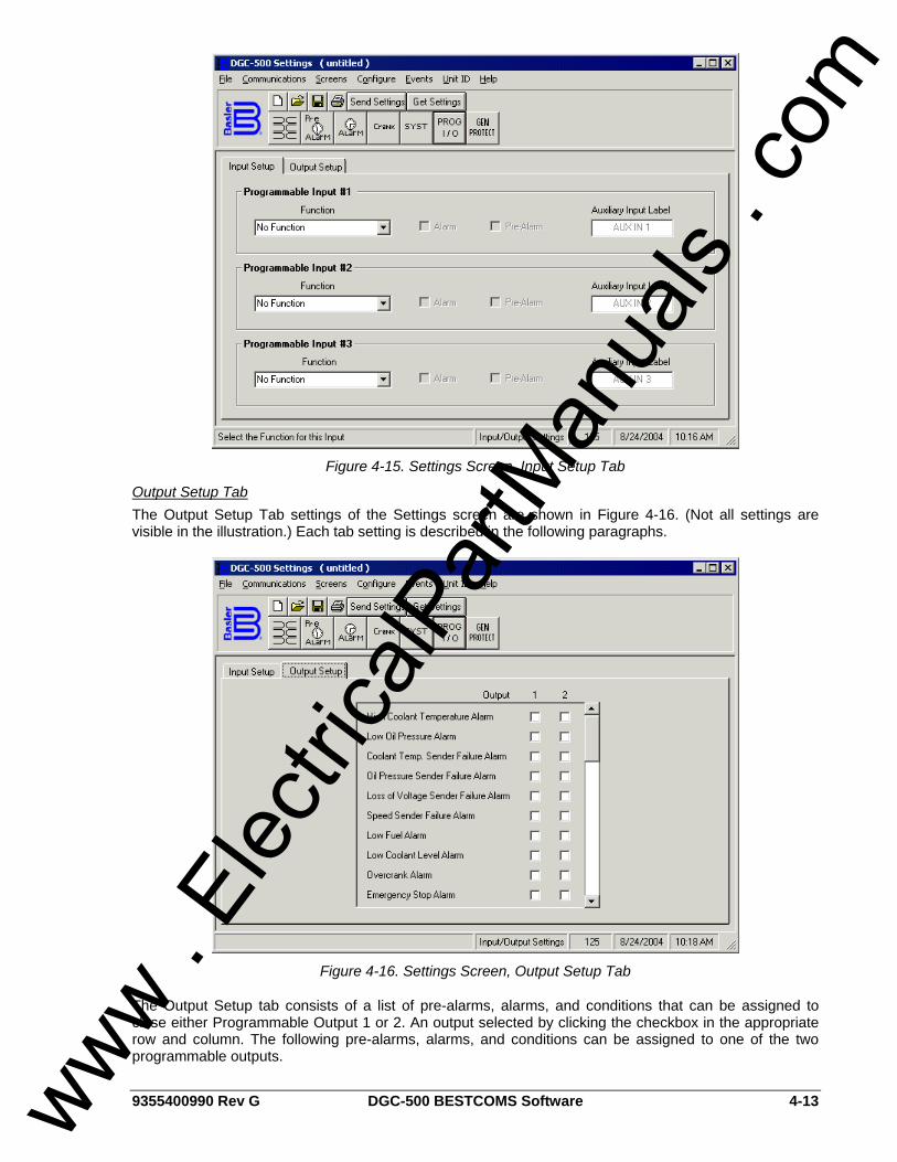
9355400990 Rev G DGC-500 BESTCOMS Software 4-13
Figure 4-15. Settings Screen, Input Setup Tab
Output Setup Tab The Output Setup Tab settings of the Settings screen are shown in Figure 4-16. (Not all settings are visible in the illustration.) Each tab setting is described in the following paragraphs.
Figure 4-16. Settings Screen, Output Setup Tab
The Output Setup tab consists of a list of pre-alarms, alarms, and conditions that can be assigned to close either Programmable Output 1 or 2. An output selected by clicking the checkbox in the appropriate row and column. The following pre-alarms, alarms, and conditions can be assigned to one of the two programmable outputs.
www . El
ectric
alPar
tMan
uals
. com
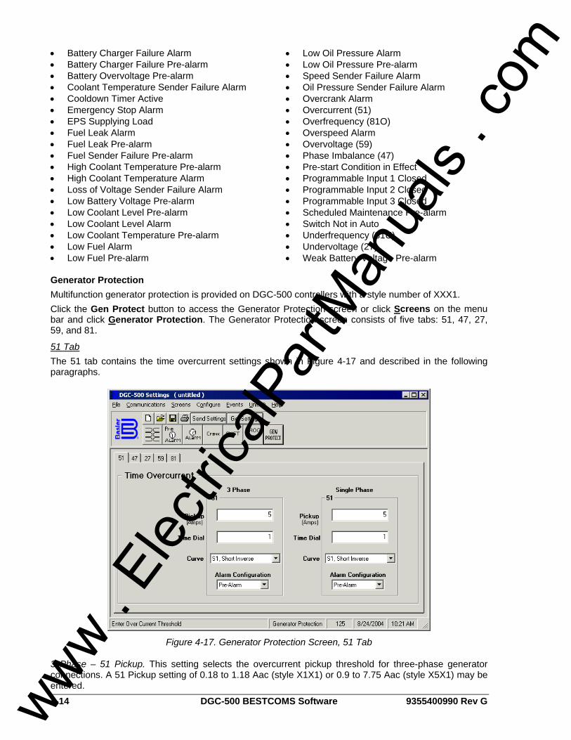
4-14 DGC-500 BESTCOMS Software 9355400990 Rev G
• Battery Charger Failure Alarm • Battery Charger Failure Pre-alarm • Battery Overvoltage Pre-alarm • Coolant Temperature Sender Failure Alarm • Cooldown Timer Active • Emergency Stop Alarm • EPS Supplying Load • Fuel Leak Alarm • Fuel Leak Pre-alarm • Fuel Sender Failure Pre-alarm • High Coolant Temperature Pre-alarm • High Coolant Temperature Alarm • Loss of Voltage Sender Failure Alarm • Low Battery Voltage Pre-alarm • Low Coolant Level Pre-alarm • Low Coolant Level Alarm • Low Coolant Temperature Pre-alarm • Low Fuel Alarm • Low Fuel Pre-alarm
• Low Oil Pressure Alarm • Low Oil Pressure Pre-alarm • Speed Sender Failure Alarm • Oil Pressure Sender Failure Alarm • Overcrank Alarm • Overcurrent (51) • Overfrequency (81O) • Overspeed Alarm • Overvoltage (59) • Phase Imbalance (47) • Pre-start Condition in Effect • Programmable Input 1 Closed • Programmable Input 2 Closed • Programmable Input 3 Closed • Scheduled Maintenance Pre-alarm • Switch Not in Auto • Underfrequency (81U) • Undervoltage (27) • Weak Battery Voltage Pre-alarm
Generator Protection Multifunction generator protection is provided on DGC-500 controllers with a style number of XXX1. Click the Gen Protect button to access the Generator Protection screen or click Screens on the menu bar and click Generator Protection. The Generator Protection screen consists of five tabs: 51, 47, 27, 59, and 81.
51 Tab The 51 tab contains the time overcurrent settings shown in Figure 4-17 and described in the following paragraphs.
Figure 4-17. Generator Protection Screen, 51 Tab
3 Phase – 51 Pickup. This setting selects the overcurrent pickup threshold for three-phase generator connections. A 51 Pickup setting of 0.18 to 1.18 Aac (style X1X1) or 0.9 to 7.75 Aac (style X5X1) may be entered.
www . El
ectric
alPar
tMan
uals
. com
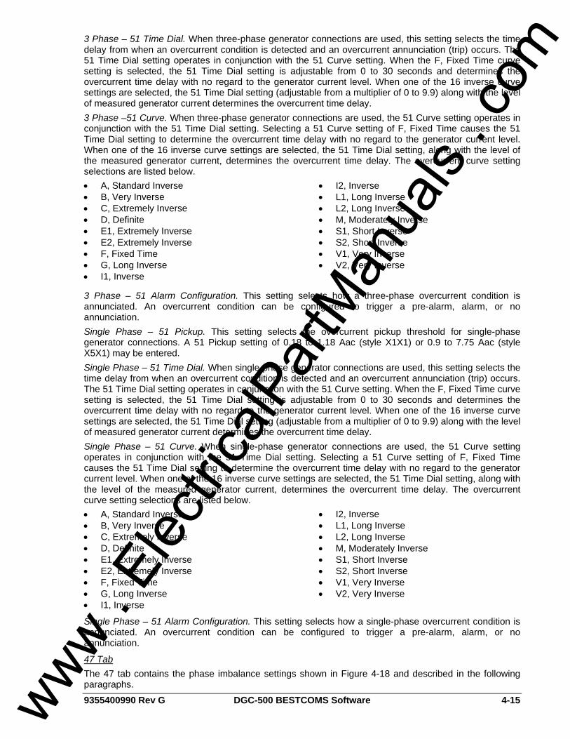
9355400990 Rev G DGC-500 BESTCOMS Software 4-15
3 Phase – 51 Time Dial. When three-phase generator connections are used, this setting selects the time delay from when an overcurrent condition is detected and an overcurrent annunciation (trip) occurs. The 51 Time Dial setting operates in conjunction with the 51 Curve setting. When the F, Fixed Time curve setting is selected, the 51 Time Dial setting is adjustable from 0 to 30 seconds and determines the overcurrent time delay with no regard to the generator current level. When one of the 16 inverse curve settings are selected, the 51 Time Dial setting (adjustable from a multiplier of 0 to 9.9) along with the level of measured generator current determines the overcurrent time delay. 3 Phase –51 Curve. When three-phase generator connections are used, the 51 Curve setting operates in conjunction with the 51 Time Dial setting. Selecting a 51 Curve setting of F, Fixed Time causes the 51 Time Dial setting to determine the overcurrent time delay with no regard to the generator current level. When one of the 16 inverse curve settings are selected, the 51 Time Dial setting, along with the level of the measured generator current, determines the overcurrent time delay. The overcurrent curve setting selections are listed below. • A, Standard Inverse • B, Very Inverse • C, Extremely Inverse • D, Definite • E1, Extremely Inverse • E2, Extremely Inverse • F, Fixed Time • G, Long Inverse • I1, Inverse
• I2, Inverse • L1, Long Inverse • L2, Long Inverse • M, Moderately Inverse • S1, Short Inverse • S2, Short Inverse • V1, Very Inverse • V2, Very Inverse
3 Phase – 51 Alarm Configuration. This setting selects how a three-phase overcurrent condition is annunciated. An overcurrent condition can be configured to trigger a pre-alarm, alarm, or no annunciation. Single Phase – 51 Pickup. This setting selects the overcurrent pickup threshold for single-phase generator connections. A 51 Pickup setting of 0.18 to 1.18 Aac (style X1X1) or 0.9 to 7.75 Aac (style X5X1) may be entered. Single Phase – 51 Time Dial. When single-phase generator connections are used, this setting selects the time delay from when an overcurrent condition is detected and an overcurrent annunciation (trip) occurs. The 51 Time Dial setting operates in conjunction with the 51 Curve setting. When the F, Fixed Time curve setting is selected, the 51 Time Dial setting is adjustable from 0 to 30 seconds and determines the overcurrent time delay with no regard to the generator current level. When one of the 16 inverse curve settings are selected, the 51 Time Dial setting (adjustable from a multiplier of 0 to 9.9) along with the level of measured generator current determines the overcurrent time delay. Single Phase – 51 Curve. When single-phase generator connections are used, the 51 Curve setting operates in conjunction with the 51 Time Dial setting. Selecting a 51 Curve setting of F, Fixed Time causes the 51 Time Dial setting to determine the overcurrent time delay with no regard to the generator current level. When one of the 16 inverse curve settings are selected, the 51 Time Dial setting, along with the level of the measured generator current, determines the overcurrent time delay. The overcurrent curve setting selections are listed below. • A, Standard Inverse • B, Very Inverse • C, Extremely Inverse • D, Definite • E1, Extremely Inverse • E2, Extremely Inverse • F, Fixed Time • G, Long Inverse • I1, Inverse
• I2, Inverse • L1, Long Inverse • L2, Long Inverse • M, Moderately Inverse • S1, Short Inverse • S2, Short Inverse • V1, Very Inverse • V2, Very Inverse
Single Phase – 51 Alarm Configuration. This setting selects how a single-phase overcurrent condition is annunciated. An overcurrent condition can be configured to trigger a pre-alarm, alarm, or no annunciation.
47 Tab The 47 tab contains the phase imbalance settings shown in Figure 4-18 and described in the following paragraphs.
www . El
ectric
alPar
tMan
uals
. com
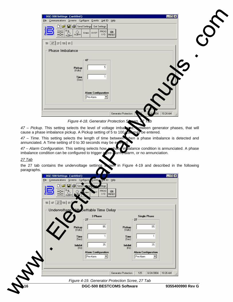
4-16 DGC-500 BESTCOMS Software 9355400990 Rev G
Figure 4-18. Generator Protection Screen, 47 Tab
47 – Pickup. This setting selects the level of voltage imbalance, between generator phases, that will cause a phase imbalance pickup. A Pickup setting of 5 to 100 Vac may be entered. 47 – Time. This setting selects the length of time between when a phase imbalance is detected and annunciated. A Time setting of 0 to 30 seconds may be entered. 47 – Alarm Configuration. This setting selects how a phase imbalance condition is annunciated. A phase imbalance condition can be configured to trigger a pre-alarm, alarm, or no annunciation.
27 Tab the 27 tab contains the undervoltage settings shown in Figure 4-19 and described in the following paragraphs.
Figure 4-19. Generator Protection Scree, 27 Tab www .
Elec
tricalP
artM
anua
ls . c
om
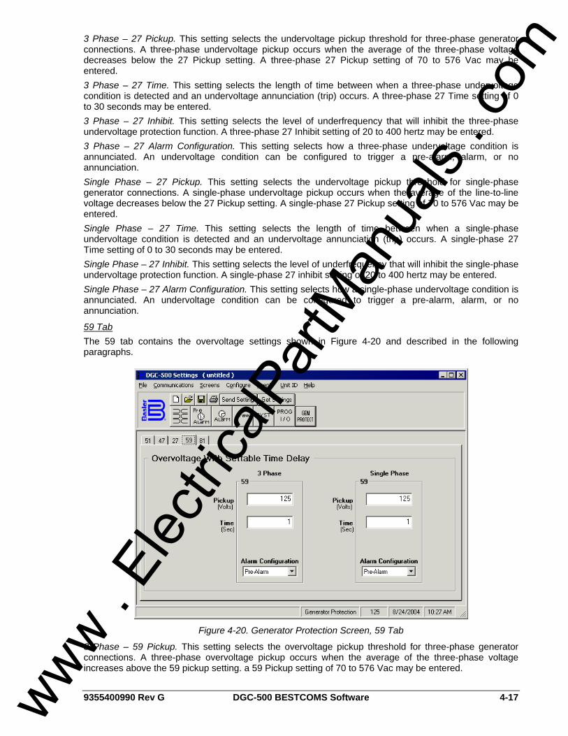
9355400990 Rev G DGC-500 BESTCOMS Software 4-17
3 Phase – 27 Pickup. This setting selects the undervoltage pickup threshold for three-phase generator connections. A three-phase undervoltage pickup occurs when the average of the three-phase voltage decreases below the 27 Pickup setting. A three-phase 27 Pickup setting of 70 to 576 Vac may be entered. 3 Phase – 27 Time. This setting selects the length of time between when a three-phase undervoltage condition is detected and an undervoltage annunciation (trip) occurs. A three-phase 27 Time setting of 0 to 30 seconds may be entered. 3 Phase – 27 Inhibit. This setting selects the level of underfrequency that will inhibit the three-phase undervoltage protection function. A three-phase 27 Inhibit setting of 20 to 400 hertz may be entered. 3 Phase – 27 Alarm Configuration. This setting selects how a three-phase undervoltage condition is annunciated. An undervoltage condition can be configured to trigger a pre-alarm, alarm, or no annunciation. Single Phase – 27 Pickup. This setting selects the undervoltage pickup threshold for single-phase generator connections. A single-phase undervoltage pickup occurs when the average of the line-to-line voltage decreases below the 27 Pickup setting. A single-phase 27 Pickup setting of 70 to 576 Vac may be entered. Single Phase – 27 Time. This setting selects the length of time between when a single-phase undervoltage condition is detected and an undervoltage annunciation (trip) occurs. A single-phase 27 Time setting of 0 to 30 seconds may be entered. Single Phase – 27 Inhibit. This setting selects the level of underfrequency that will inhibit the single-phase undervoltage protection function. A single-phase 27 inhibit setting of 20 to 400 hertz may be entered. Single Phase – 27 Alarm Configuration. This setting selects how a single-phase undervoltage condition is annunciated. An undervoltage condition can be configured to trigger a pre-alarm, alarm, or no annunciation.
59 Tab The 59 tab contains the overvoltage settings shown in Figure 4-20 and described in the following paragraphs.
Figure 4-20. Generator Protection Screen, 59 Tab
3 Phase – 59 Pickup. This setting selects the overvoltage pickup threshold for three-phase generator connections. A three-phase overvoltage pickup occurs when the average of the three-phase voltage increases above the 59 pickup setting. a 59 Pickup setting of 70 to 576 Vac may be entered.
www . El
ectric
alPar
tMan
uals
. com
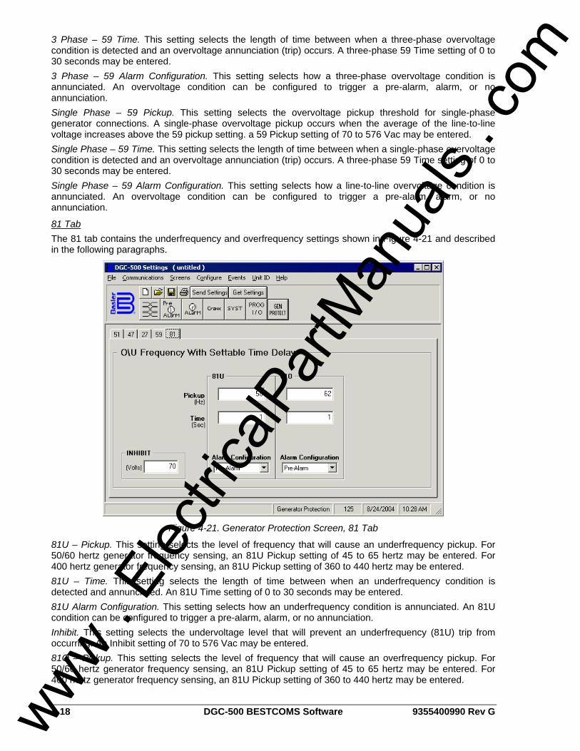
4-18 DGC-500 BESTCOMS Software 9355400990 Rev G
3 Phase – 59 Time. This setting selects the length of time between when a three-phase overvoltage condition is detected and an overvoltage annunciation (trip) occurs. A three-phase 59 Time setting of 0 to 30 seconds may be entered. 3 Phase – 59 Alarm Configuration. This setting selects how a three-phase overvoltage condition is annunciated. An overvoltage condition can be configured to trigger a pre-alarm, alarm, or no annunciation. Single Phase – 59 Pickup. This setting selects the overvoltage pickup threshold for single-phase generator connections. A single-phase overvoltage pickup occurs when the average of the line-to-line voltage increases above the 59 pickup setting. a 59 Pickup setting of 70 to 576 Vac may be entered. Single Phase – 59 Time. This setting selects the length of time between when a single-phase overvoltage condition is detected and an overvoltage annunciation (trip) occurs. A three-phase 59 Time setting of 0 to 30 seconds may be entered. Single Phase – 59 Alarm Configuration. This setting selects how a line-to-line overvoltage condition is annunciated. An overvoltage condition can be configured to trigger a pre-alarm, alarm, or no annunciation.
81 Tab The 81 tab contains the underfrequency and overfrequency settings shown in Figure 4-21 and described in the following paragraphs.
Figure 4-21. Generator Protection Screen, 81 Tab
81U – Pickup. This setting selects the level of frequency that will cause an underfrequency pickup. For 50/60 hertz generator frequency sensing, an 81U Pickup setting of 45 to 65 hertz may be entered. For 400 hertz generator frequency sensing, an 81U Pickup setting of 360 to 440 hertz may be entered. 81U – Time. This setting selects the length of time between when an underfrequency condition is detected and annunciated. An 81U Time setting of 0 to 30 seconds may be entered. 81U Alarm Configuration. This setting selects how an underfrequency condition is annunciated. An 81U condition can be configured to trigger a pre-alarm, alarm, or no annunciation. Inhibit. This setting selects the undervoltage level that will prevent an underfrequency (81U) trip from occurring. An Inhibit setting of 70 to 576 Vac may be entered. 81O – Pickup. This setting selects the level of frequency that will cause an overfrequency pickup. For 50/60 hertz generator frequency sensing, an 81U Pickup setting of 45 to 65 hertz may be entered. For 400 hertz generator frequency sensing, an 81U Pickup setting of 360 to 440 hertz may be entered.
www . El
ectric
alPar
tMan
uals
. com
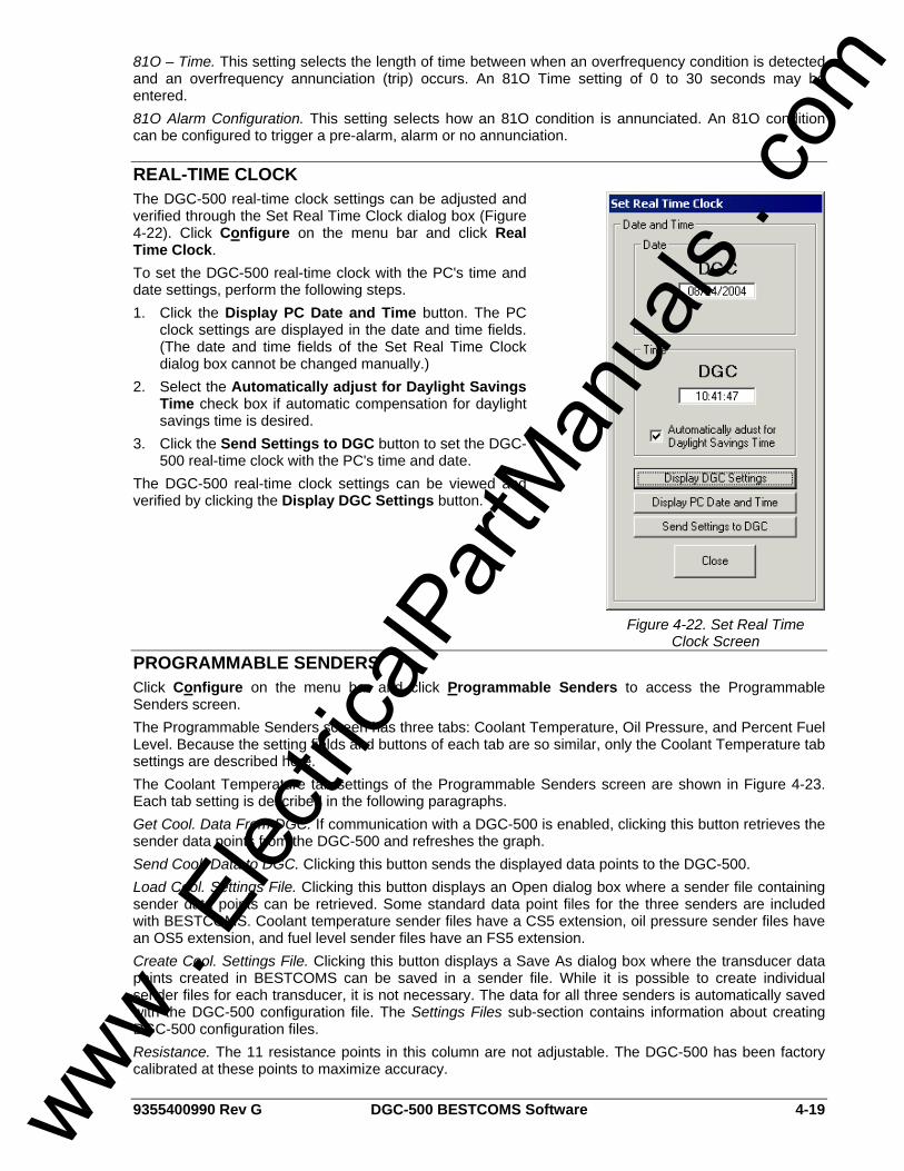
9355400990 Rev G DGC-500 BESTCOMS Software 4-19
Figure 4-22. Set Real Time Clock Screen
81O – Time. This setting selects the length of time between when an overfrequency condition is detected and an overfrequency annunciation (trip) occurs. An 81O Time setting of 0 to 30 seconds may be entered. 81O Alarm Configuration. This setting selects how an 81O condition is annunciated. An 81O condition can be configured to trigger a pre-alarm, alarm or no annunciation.
REAL-TIME CLOCK The DGC-500 real-time clock settings can be adjusted and verified through the Set Real Time Clock dialog box (Figure 4-22). Click Configure on the menu bar and click Real Time Clock. To set the DGC-500 real-time clock with the PC's time and date settings, perform the following steps. 1. Click the Display PC Date and Time button. The PC
clock settings are displayed in the date and time fields. (The date and time fields of the Set Real Time Clock dialog box cannot be changed manually.)
2. Select the Automatically adjust for Daylight Savings Time check box if automatic compensation for daylight savings time is desired.
3. Click the Send Settings to DGC button to set the DGC-500 real-time clock with the PC's time and date.
The DGC-500 real-time clock settings can be viewed and verified by clicking the Display DGC Settings button.
PROGRAMMABLE SENDERS Click Configure on the menu bar and click Programmable Senders to access the Programmable Senders screen. The Programmable Senders screen has three tabs: Coolant Temperature, Oil Pressure, and Percent Fuel Level. Because the setting fields and buttons of each tab are so similar, only the Coolant Temperature tab settings are described here. The Coolant Temperature tab settings of the Programmable Senders screen are shown in Figure 4-23. Each tab setting is described in the following paragraphs. Get Cool. Data From DGC. If communication with a DGC-500 is enabled, clicking this button retrieves the sender data points from the DGC-500 and refreshes the graph. Send Cool. Data to DGC. Clicking this button sends the displayed data points to the DGC-500. Load Cool. Settings File. Clicking this button displays an Open dialog box where a sender file containing sender data points can be retrieved. Some standard data point files for the three senders are included with BESTCOMS. Coolant temperature sender files have a CS5 extension, oil pressure sender files have an OS5 extension, and fuel level sender files have an FS5 extension. Create Cool. Settings File. Clicking this button displays a Save As dialog box where the transducer data points created in BESTCOMS can be saved in a sender file. While it is possible to create individual sender files for each transducer, it is not necessary. The data for all three senders is automatically saved with the DGC-500 configuration file. The Settings Files sub-section contains information about creating DGC-500 configuration files. Resistance. The 11 resistance points in this column are not adjustable. The DGC-500 has been factory calibrated at these points to maximize accuracy.
www . El
ectric
alPar
tMan
uals
. com
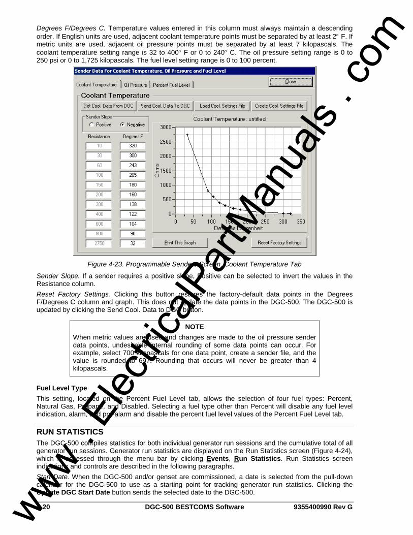
4-20 DGC-500 BESTCOMS Software 9355400990 Rev G
Degrees F/Degrees C. Temperature values entered in this column must always maintain a descending order. If English units are used, adjacent coolant temperature points must be separated by at least 2° F. If metric units are used, adjacent oil pressure points must be separated by at least 7 kilopascals. The coolant temperature setting range is 32 to 400° F or 0 to 240° C. The oil pressure setting range is 0 to 250 psi or 0 to 1,725 kilopascals. The fuel level setting range is 0 to 100 percent.
Figure 4-23. Programmable Senders Screen, Coolant Temperature Tab
Sender Slope. If a sender requires a positive slope, Positive can be selected to invert the values in the Resistance column. Reset Factory Settings. Clicking this button restores the factory-default data points in the Degrees F/Degrees C column and graph. This does not update the data points in the DGC-500. The DGC-500 is updated by clicking the Send Cool. Data to DGC button.
Fuel Level Type This setting, located on the Percent Fuel Level tab, allows the selection of four fuel types: Percent, Natural Gas, Propane, and Disabled. Selecting a fuel type other than Percent will disable any fuel level indication, alarm, and pre-alarm and disable the percent fuel level values of the Percent Fuel Level tab.
RUN STATISTICS The DGC-500 compiles statistics for both individual generator run sessions and the cumulative total of all generator run sessions. Generator run statistics are displayed on the Run Statistics screen (Figure 4-24), which is accessed through the menu bar by clicking Events, Run Statistics. Run Statistics screen indications and controls are described in the following paragraphs. Start Date. When the DGC-500 and/or genset are commissioned, a date is selected from the pull-down calendar for the DGC-500 to use as a starting point for tracking generator run statistics. Clicking the Update DGC Start Date button sends the selected date to the DGC-500.
NOTE When metric values are used and changes are made to the oil pressure sender data points, undesirable internal rounding of some data points can occur. For example, select 700 kilopascals for one data point, create a sender file, and the value is rounded to 697. Rounding that occurs will never be greater than 4 kilopascals.
www . El
ectric
alPar
tMan
uals
. com
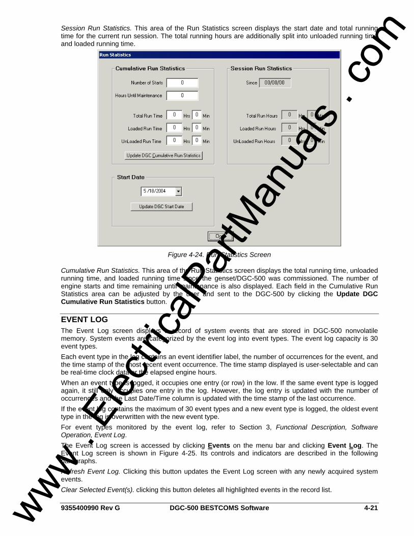
9355400990 Rev G DGC-500 BESTCOMS Software 4-21
Session Run Statistics. This area of the Run Statistics screen displays the start date and total running time for the current run session. The total running hours are additionally split into unloaded running time and loaded running time.
Figure 4-24. Run Statistics Screen
Cumulative Run Statistics. This area of the Run Statistics screen displays the total running time, unloaded running time, and loaded running time since the genset/DGC-500 was commissioned. The number of engine starts and time remaining until maintenance is also displayed. Each field in the Cumulative Run Statistics area can be adjusted by the user and sent to the DGC-500 by clicking the Update DGC Cumulative Run Statistics button.
EVENT LOG The Event Log screen displays a record of system events that are stored in DGC-500 nonvolatile memory. System events are categorized by the event log into event types. The event log capacity is 30 event types. Each event type in the log contains an event identifier label, the number of occurrences for the event, and the time stamp of the most recent event occurrence. The time stamp displayed is user-selectable and can be real-time clock data or the elapsed engine hours. When an event type is logged, it occupies one entry (or row) in the low. If the same event type is logged again, it still only occupies one entry in the log. However, the log entry is updated with the number of occurrences and the Last Date/Time column is updated with the time stamp of the last occurrence. If the event log contains the maximum of 30 event types and a new event type is logged, the oldest event type in the log is overwritten with the new event type. For event types monitored by the event log, refer to Section 3, Functional Description, Software Operation, Event Log. The Event Log screen is accessed by clicking Events on the menu bar and clicking Event Log. The Event Log screen is shown in Figure 4-25. Its controls and indicators are described in the following paragraphs. Refresh Event Log. Clicking this button updates the Event Log screen with any newly acquired system events. Clear Selected Event(s). clicking this button deletes all highlighted events in the record list.
www . El
ectric
alPar
tMan
uals
. com
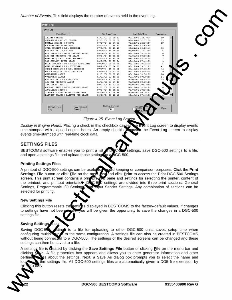
4-22 DGC-500 BESTCOMS Software 9355400990 Rev G
Number of Events. This field displays the number of events held in the event log.
Figure 4-25. Event Log Screen
Display in Engine Hours. Placing a check in this checkbox causes the Event Log screen to display events time-stamped with elapsed engine hours. An empty checkbox causes the Event Log screen to display events time-stamped with real-time clock data.
SETTINGS FILES BESTCOMS software enables you to print a list of DGC-500 settings, save DGC-500 settings to a file, and open a settings file and upload those settings to a DGC-500.
Printing Settings Files A printout of DGC-500 settings can be useful for record keeping or comparison purposes. Click the Print Settings File button or click File on the menu bar and click Print to access the Print DGC-500 Settings screen. This print screen contains a print-preview pane and settings for selecting the printer, content of the printout, and printout orientation. DGC-500 settings are divided into three print sections: General Settings, Programmable I/O Settings, and Input Sender Settings. Any combination of sections can be selected for printing.
New Settings File Clicking this button resets the settings displayed in BESTCOMS to the factory-default values. If changes to settings have not been saved, you will be given the opportunity to save the changes in a DGC-500 settings file.
Saving Settings Files Saving DGC-500 settings to a file for uploading to other DGC-500 units saves setup time when configuring multiple units to the same configuration. A settings file can also be created in BESTCOMS without being connected to a DGC-500. The settings of the desired screens can be changed and these settings can then be saved to a file. A settings file is created by clicking the Save Settings File button or clicking File on the menu bar and clicking Save. A file properties box appears and allows you to enter generator information and other pertinent notes about the settings. Next, a Save As dialog box prompts you to select the name and location of the settings file. All DGC-500 settings files are automatically given a DG5 file extension by BESTCOMS.
www . El
ectric
alPar
tMan
uals
. com
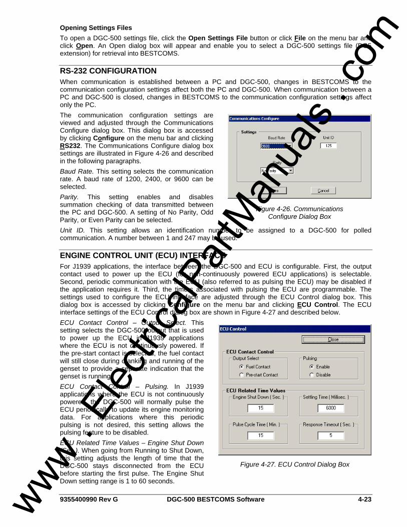
9355400990 Rev G DGC-500 BESTCOMS Software 4-23
Opening Settings Files To open a DGC-500 settings file, click the Open Settings File button or click File on the menu bar and click Open. An Open dialog box will appear and enable you to select a DGC-500 settings file (DG5 extension) for retrieval into BESTCOMS.
RS-232 CONFIGURATION When communication is established between a PC and DGC-500, changes in BESTCOMS to the communication configuration settings affect both the PC and DGC-500. When communication between a PC and DGC-500 is closed, changes in BESTCOMS to the communication configuration settings affect only the PC. The communication configuration settings are viewed and adjusted through the Communications Configure dialog box. This dialog box is accessed by clicking Configure on the menu bar and clicking RS232. The Communications Configure dialog box settings are illustrated in Figure 4-26 and described in the following paragraphs. Baud Rate. This setting selects the communication rate. A baud rate of 1200, 2400, or 9600 can be selected. Parity. This setting enables and disables summation checking of data transmitted between the PC and DGC-500. A setting of No Parity, Odd Parity, or Even Parity can be selected. Unit ID. This setting allows an identification number to be assigned to a DGC-500 for polled communication. A number between 1 and 247 may be used.
ENGINE CONTROL UNIT (ECU) INTERFACE For J1939 applications, the interface between the DGC-500 and ECU is configurable. First, the output contact used to power up the ECU (for non-continuously powered ECU applications) is selectable. Second, periodic communication with the ECU (also referred to as pulsing the ECU) may be disabled if the application requires it. Third, the timers associated with pulsing the ECU are programmable. The settings used to configure the ECU interface are adjusted through the ECU Control dialog box. This dialog box is accessed by clicking Configure on the menu bar and clicking ECU Control. The ECU interface settings of the ECU Control dialog box are shown in Figure 4-27 and described below. ECU Contact Control – Output Select. This setting selects the DGC-500 output that is used to power up the ECU in J1939 applications where the ECU is not continuously powered. If the pre-start contact is selected, the fuel contact will still close during cranking and running of the genset to provide a separate indication that the genset is running. ECU Contact Control – Pulsing. In J1939 applications where the ECU is not continuously powered, the DGC-500 will normally pulse the ECU periodically to update its engine monitoring data. For applications where this periodic pulsing is not desired, this setting allows the pulsing feature to be disabled. ECU Related Time Values – Engine Shut Down (Sec.). When going from Running to Shut Down, this setting adjusts the length of time that the DGC-500 stays disconnected from the ECU before starting the first pulse. The Engine Shut Down setting range is 1 to 60 seconds.
Figure 4-26. Communications Configure Dialog Box
Figure 4-27. ECU Control Dialog Box
www . El
ectric
alPar
tMan
uals
. com
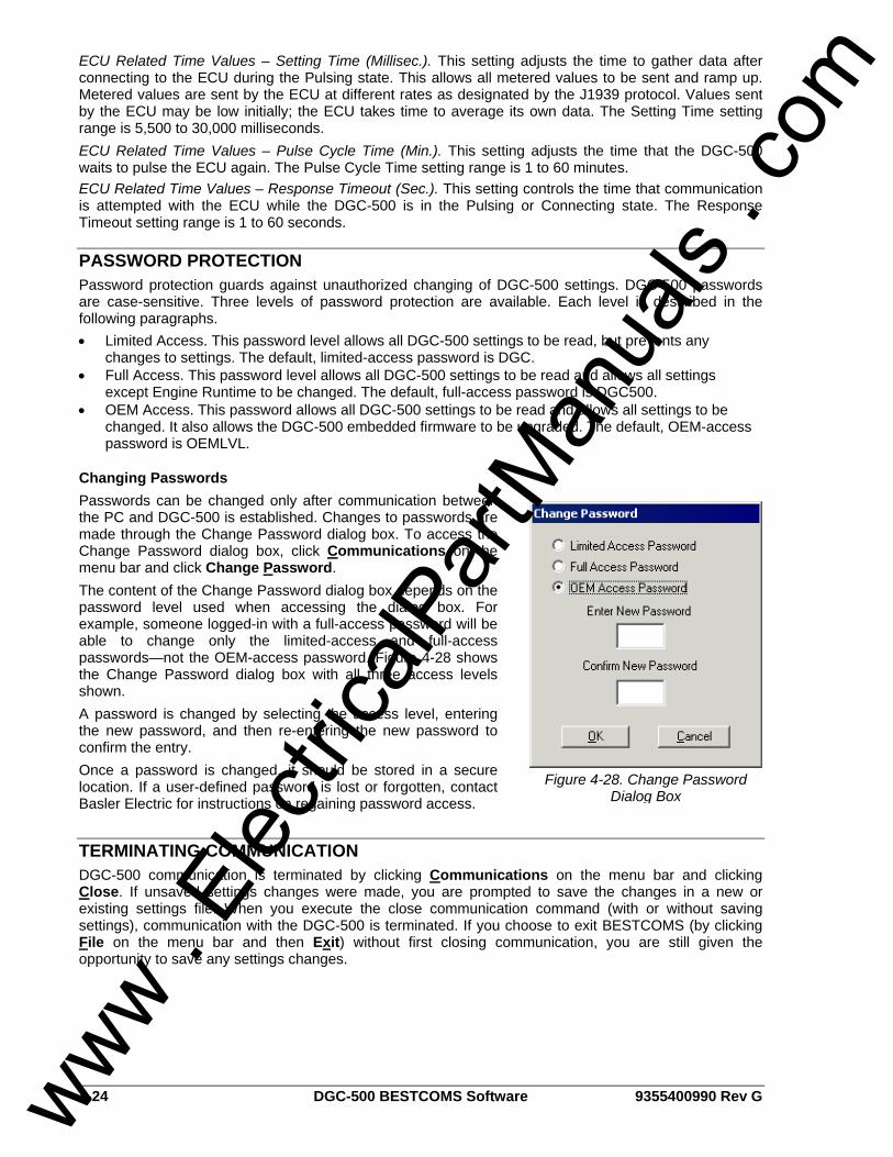
4-24 DGC-500 BESTCOMS Software 9355400990 Rev G
ECU Related Time Values – Setting Time (Millisec.). This setting adjusts the time to gather data after connecting to the ECU during the Pulsing state. This allows all metered values to be sent and ramp up. Metered values are sent by the ECU at different rates as designated by the J1939 protocol. Values sent by the ECU may be low initially; the ECU takes time to average its own data. The Setting Time setting range is 5,500 to 30,000 milliseconds. ECU Related Time Values – Pulse Cycle Time (Min.). This setting adjusts the time that the DGC-500 waits to pulse the ECU again. The Pulse Cycle Time setting range is 1 to 60 minutes. ECU Related Time Values – Response Timeout (Sec.). This setting controls the time that communication is attempted with the ECU while the DGC-500 is in the Pulsing or Connecting state. The Response Timeout setting range is 1 to 60 seconds.
PASSWORD PROTECTION Password protection guards against unauthorized changing of DGC-500 settings. DGC-500 passwords are case-sensitive. Three levels of password protection are available. Each level is described in the following paragraphs. • Limited Access. This password level allows all DGC-500 settings to be read, but prevents any
changes to settings. The default, limited-access password is DGC. • Full Access. This password level allows all DGC-500 settings to be read and allows all settings
except Engine Runtime to be changed. The default, full-access password is DGC500. • OEM Access. This password allows all DGC-500 settings to be read and allows all settings to be
changed. It also allows the DGC-500 embedded firmware to be upgraded. The default, OEM-access password is OEMLVL.
Changing Passwords Passwords can be changed only after communication between the PC and DGC-500 is established. Changes to passwords are made through the Change Password dialog box. To access the Change Password dialog box, click Communications on the menu bar and click Change Password. The content of the Change Password dialog box depends on the password level used when accessing the dialog box. For example, someone logged-in with a full-access password will be able to change only the limited-access and full-access passwords—not the OEM-access password. Figure 4-28 shows the Change Password dialog box with all three access levels shown. A password is changed by selecting the access level, entering the new password, and then re-entering the new password to confirm the entry. Once a password is changed, it should be stored in a secure location. If a user-defined password is lost or forgotten, contact Basler Electric for instructions on regaining password access.
TERMINATING COMMUNICATION DGC-500 communication is terminated by clicking Communications on the menu bar and clicking Close. If unsaved settings changes were made, you are prompted to save the changes in a new or existing settings file. When you execute the close communication command (with or without saving settings), communication with the DGC-500 is terminated. If you choose to exit BESTCOMS (by clicking File on the menu bar and then Exit) without first closing communication, you are still given the opportunity to save any settings changes.
Figure 4-28. Change Password Dialog Box
www . El
ectric
alPar
tMan
uals
. com
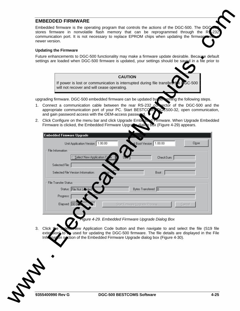
9355400990 Rev G DGC-500 BESTCOMS Software 4-25
EMBEDDED FIRMWARE Embedded firmware is the operating program that controls the actions of the DGC-500. The DGC-500 stores firmware in nonvolatile flash memory that can be reprogrammed through the RS-232 communication port. It is not necessary to replace EPROM chips when updating the firmware with a newer version.
Updating the Firmware Future enhancements to DGC-500 functionality may make a firmware update desirable. Because default settings are loaded when DGC-500 firmware is updated, your settings should be saved in a file prior to
upgrading firmware. DGC-500 embedded firmware can be updated by performing the following steps. 1. Connect a communication cable between the rear RS-232 connector of the DGC-500 and the
appropriate communication port of your PC. Start BESTCOMS-DGC500-32, open communication, and gain password access with the OEM-access password.
2. Click Configure on the menu bar and click Upgrade Embedded Firmware. When Upgrade Embedded Firmware is clicked, the Embedded Firmware Upgrade dialog box (Figure 4-29) appears.
Figure 4-29. Embedded Firmware Upgrade Dialog Box
3. Click the Select New Application Code button and then navigate to and select the file (S19 file extension) to be used for updating the DGC-500 firmware. The file details are displayed in the File Information section of the Embedded Firmware Upgrade dialog box (Figure 4-30).
CAUTION If power is lost or communication is interrupted during file transfer, the DGC-500 will not recover and will cease operating.
www . El
ectric
alPar
tMan
uals
. com
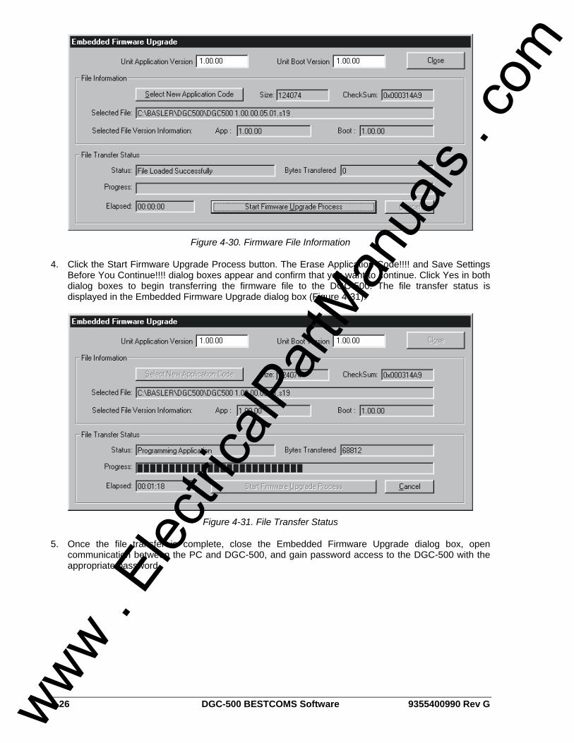
4-26 DGC-500 BESTCOMS Software 9355400990 Rev G
Figure 4-30. Firmware File Information
4. Click the Start Firmware Upgrade Process button. The Erase Application Code!!!! and Save Settings Before You Continue!!!! dialog boxes appear and confirm that you want to continue. Click Yes in both dialog boxes to begin transferring the firmware file to the DGC-500. The file transfer status is displayed in the Embedded Firmware Upgrade dialog box (Figure 4-31).
Figure 4-31. File Transfer Status
5. Once the file transfer is complete, close the Embedded Firmware Upgrade dialog box, open communication between the PC and DGC-500, and gain password access to the DGC-500 with the appropriate password.
www . El
ectric
alPar
tMan
uals
. com
9355400990 Rev G DGC-500 Installation i
SECTION 5 • INSTALLATION TABLE OF CONTENTS
SECTION 5 • INSTALLATION .................................................................................................................. 5-1
GENERAL.............................................................................................................................................. 5-1 PRODUCT REGISTRATION ................................................................................................................. 5-1 HARDWARE .......................................................................................................................................... 5-1 MOUNTING............................................................................................................................................ 5-1
DGC-500 Isolator Kit .......................................................................................................................... 5-2 CONNECTIONS .................................................................................................................................... 5-3
DGC-500 Terminations ...................................................................................................................... 5-3 Serial Communication Port................................................................................................................. 5-3 CAN Connections............................................................................................................................... 5-4 DGC-500 Connections for Typical Applications ................................................................................. 5-5 Volvo Penta EDC III Applications..................................................................................................... 5-10 Special Contact Sensing Input Considerations ................................................................................ 5-15
CALIBRATION ..................................................................................................................................... 5-15 Equipment Required......................................................................................................................... 5-15 Entering Calibration Mode................................................................................................................ 5-16 Calibration Procedure....................................................................................................................... 5-16
Figures Figure 5-1. DGC-500 Cutout Dimensions ................................................................................................. 5-1 Figure 5-2. DGC-500 Overall Dimensions................................................................................................. 5-2 Figure 5-3. DGC-500 Communication Port Pin Assignments ................................................................... 5-3 Figure 5-4. Personal Computer to DGC-500 Connections........................................................................ 5-4 Figure 5-5. CAN Cable Assembly.............................................................................................................. 5-4 Figure 5-6. Typical DGC-500 CAN Interface Connections........................................................................ 5-5 Figure 5-7. DGC-500 Connections, Single-Phase, A-B ............................................................................ 5-6 Figure 5-8. DGC-500 Connections, Single-Phase, A-C ............................................................................ 5-7 Figure 5-9. DGC-500 Connections, Three-Phase Delta ........................................................................... 5-8 Figure 5-10. DGC-500 Connections, Three-Phase Wye........................................................................... 5-9 Figure 5-11. Volvo Penta EDC III Application, Single-Phase, A-B Connections..................................... 5-11 Figure 5-12. Volvo Penta EDC III Application, Single-Phase, A-C Connections .................................... 5-12 Figure 5-13. Volvo Penta EDC III Application, Three-Phase, Delta Connections................................... 5-13 Figure 5-14. Volvo Penta EDC III Application, Three-Phase, Wye Connections .................................... 5-14 Figure 5-15. Contact Sensing Input Connections with Noise Suppression Diodes ................................ 5-15 Figure 5-16. Calibration Mode Navigation............................................................................................... 5-16 Figure 5-17. Successful and Unsuccessful Calibration Screens............................................................. 5-16
Tables Table 5-1. DGC-500 Communication Port Pin Functions ......................................................................... 5-3 Table 5-2. CAN Cable Assembly Termination Assignments..................................................................... 5-4
www . El
ectric
alPar
tMan
uals
. com

ii DGC-500 Installation 9355400990 Rev G
This page intentionally left blank.
www . El
ectric
alPar
tMan
uals
. com
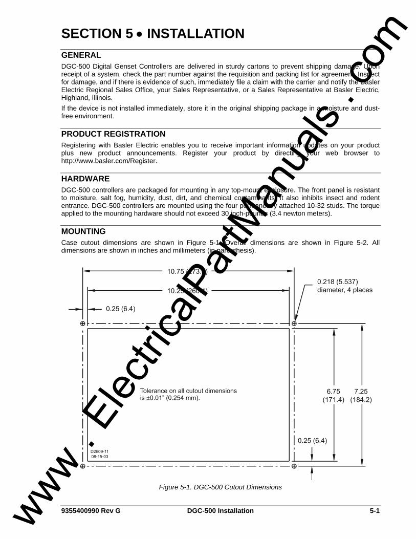
9355400990 Rev G DGC-500 Installation 5-1
SECTION 5 • INSTALLATION GENERAL DGC-500 Digital Genset Controllers are delivered in sturdy cartons to prevent shipping damage. Upon receipt of a system, check the part number against the requisition and packing list for agreement. Inspect for damage, and if there is evidence of such, immediately file a claim with the carrier and notify the Basler Electric Regional Sales Office, your Sales Representative, or a Sales Representative at Basler Electric, Highland, Illinois. If the device is not installed immediately, store it in the original shipping package in a moisture and dust-free environment.
PRODUCT REGISTRATION Registering with Basler Electric enables you to receive important information updates on your product plus new product announcements. Register your product by directing your web browser to http://www.basler.com/Register.
HARDWARE DGC-500 controllers are packaged for mounting in any top-mount enclosure. The front panel is resistant to moisture, salt fog, humidity, dust, dirt, and chemical contaminants. It also inhibits insect and rodent entrance. DGC-500 controllers are mounted using the four permanently attached 10-32 studs. The torque applied to the mounting hardware should not exceed 30 inch-pounds (3.4 newton meters).
MOUNTING Case cutout dimensions are shown in Figure 5-1. Overall dimensions are shown in Figure 5-2. All dimensions are shown in inches and millimeters (in parenthesis).
Figure 5-1. DGC-500 Cutout Dimensions
www . El
ectric
alPar
tMan
uals
. com
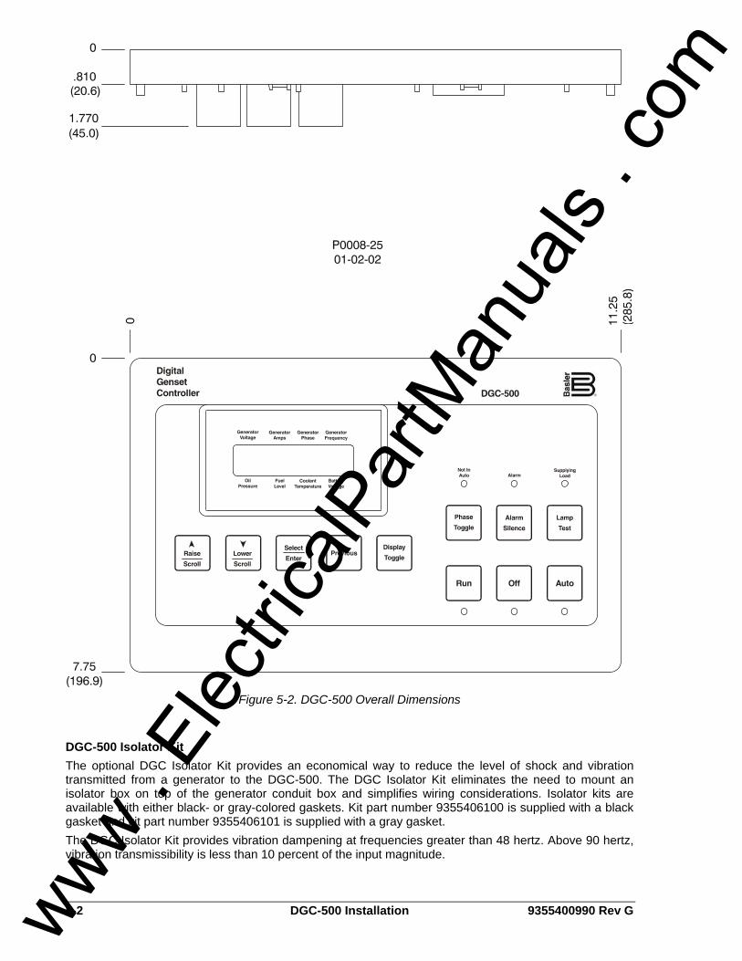
5-2 DGC-500 Installation 9355400990 Rev G
Figure 5-2. DGC-500 Overall Dimensions
DGC-500 Isolator Kit The optional DGC Isolator Kit provides an economical way to reduce the level of shock and vibration transmitted from a generator to the DGC-500. The DGC Isolator Kit eliminates the need to mount an isolator box on top of the generator conduit box and simplifies wiring considerations. Isolator kits are available with either black- or gray-colored gaskets. Kit part number 9355406100 is supplied with a black gasket and kit part number 9355406101 is supplied with a gray gasket. The DGC Isolator Kit provides vibration dampening at frequencies greater than 48 hertz. Above 90 hertz, vibration transmissibility is less than 10 percent of the input magnitude.
www . El
ectric
alPar
tMan
uals
. com
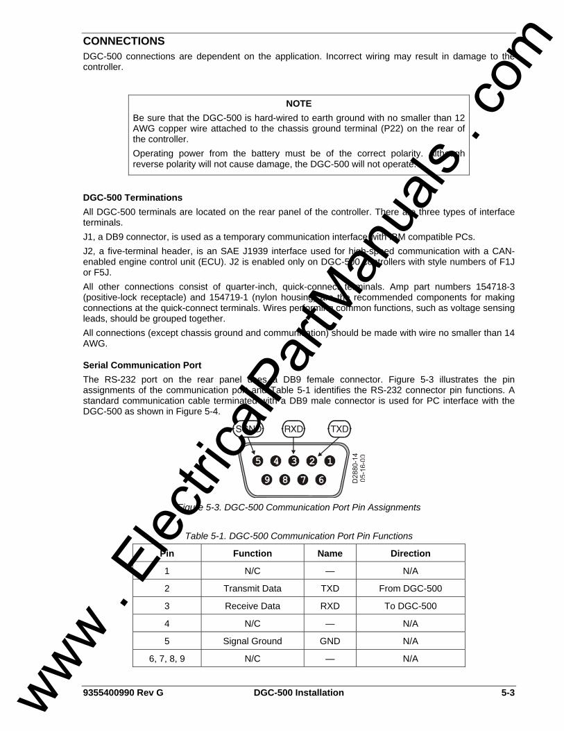
9355400990 Rev G DGC-500 Installation 5-3
CONNECTIONS DGC-500 connections are dependent on the application. Incorrect wiring may result in damage to the controller.
DGC-500 Terminations All DGC-500 terminals are located on the rear panel of the controller. There are three types of interface terminals. J1, a DB9 connector, is used as a temporary communication interface with IBM compatible PCs. J2, a five-terminal header, is an SAE J1939 interface used for high-speed communication with a CAN-enabled engine control unit (ECU). J2 is enabled only on DGC-500 controllers with style numbers of F1J or F5J. All other connections consist of quarter-inch, quick-connect terminals. Amp part numbers 154718-3 (positive-lock receptacle) and 154719-1 (nylon housing) are the recommended components for making connections at the quick-connect terminals. Wires performing common functions, such as voltage sensing leads, should be grouped together. All connections (except chassis ground and communication) should be made with wire no smaller than 14 AWG.
Serial Communication Port The RS-232 port on the rear panel uses a DB9 female connector. Figure 5-3 illustrates the pin assignments of the communication port and Table 5-1 identifies the RS-232 connector pin functions. A standard communication cable terminated with a DB9 male connector is used for PC interface with the DGC-500 as shown in Figure 5-4.
Figure 5-3. DGC-500 Communication Port Pin Assignments
Table 5-1. DGC-500 Communication Port Pin Functions
Pin Function Name Direction
1 N/C — N/A
2 Transmit Data TXD From DGC-500
3 Receive Data RXD To DGC-500
4 N/C — N/A
5 Signal Ground GND N/A
6, 7, 8, 9 N/C — N/A
NOTE Be sure that the DGC-500 is hard-wired to earth ground with no smaller than 12 AWG copper wire attached to the chassis ground terminal (P22) on the rear of the controller. Operating power from the battery must be of the correct polarity. Although reverse polarity will not cause damage, the DGC-500 will not operate.
www . El
ectric
alPar
tMan
uals
. com
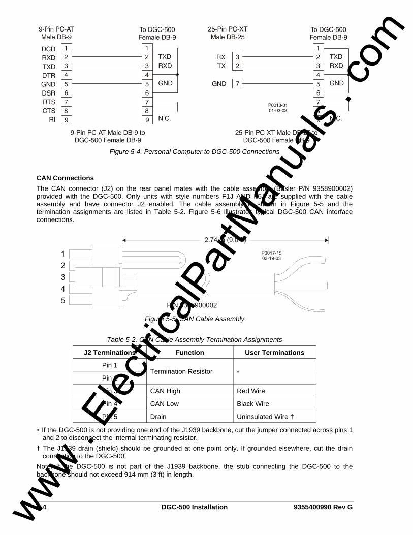
5-4 DGC-500 Installation 9355400990 Rev G
Figure 5-4. Personal Computer to DGC-500 Connections
CAN Connections The CAN connector (J2) on the rear panel mates with the cable assembly (Basler P/N 9358900002) provided with the DGC-500. Only units with style numbers F1J AND F5J are supplied with the cable assembly and have connector J2 enabled. The cable assembly is shown in Figure 5-5 and the termination assignments are listed in Table 5-2. Figure 5-6 illustrates typical DGC-500 CAN interface connections.
Figure 5-5. CAN Cable Assembly
Table 5-2. CAN Cable Assembly Termination Assignments
J2 Terminations Function User Terminations
Pin 1
Pin 2 Termination Resistor ∗
Pin 3 CAN High Red Wire
Pin 4 CAN Low Black Wire
Pin 5 Drain Uninsulated Wire †
∗ If the DGC-500 is not providing one end of the J1939 backbone, cut the jumper connected across pins 1 and 2 to disconnect the internal terminating resistor.
† The J1939 drain (shield) should be grounded at one point only. If grounded elsewhere, cut the drain connection to the DGC-500.
Note: If the DGC-500 is not part of the J1939 backbone, the stub connecting the DGC-500 to the backbone should not exceed 914 mm (3 ft) in length.
www . El
ectric
alPar
tMan
uals
. com
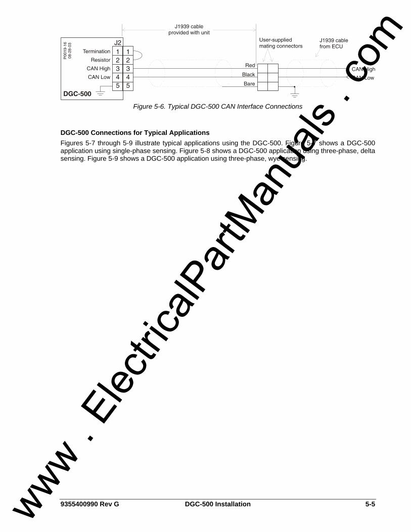
9355400990 Rev G DGC-500 Installation 5-5
Figure 5-6. Typical DGC-500 CAN Interface Connections
DGC-500 Connections for Typical Applications Figures 5-7 through 5-9 illustrate typical applications using the DGC-500. Figure 5-7 shows a DGC-500 application using single-phase sensing. Figure 5-8 shows a DGC-500 application using three-phase, delta sensing. Figure 5-9 shows a DGC-500 application using three-phase, wye sensing.
www . El
ectric
alPar
tMan
uals
. com
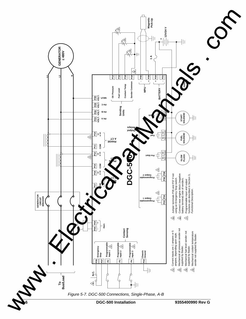
5-6 DGC-500 Installation 9355400990 Rev G
P4P3P2P37
P35
ProgrammableOutput 2
ProgrammableOutput 1
Pre-Start
Fuel
Crank
GEN
ERA
TOR
CIR
CUI
TBR
EAKE
R
P17
P14
P11
STA
RT
SOLE
NOID
SOLE
NOID
FUEL
P36
P38
P33
P34
K1
N.O
.
Emer
genc
ySt
op
Prog
ram
mab
leIn
put 2
Prog
ram
mab
leIn
put 3
Chas
sis
Gro
und
Con
tact
Sens
ing
OutputRelays
CO
M1A or 5
A
PhaseC CT
B CTPhase
CO
M
A CTPHASE
CO
M
PH A
PH B
PH C
Oil
Pres
sure
Fuel
Lev
el
Coo
lant
Tem
p
Send
ing
Uni
ts
P40
P39
- +
MPU
P20
P21
BA
TTER
Y
12V/
24 V
+
GEN
ERA
TOR
-+
DG
C-5
00
ToB
us/L
oad N
.C.
480
V
P30
P23
P26
P29
VOLT
.VO
LT.
VOLT
.VO
LT.
NEUT.
Inpu
t 1Pr
ogra
mm
able
P000
8-23
03-3
1-03
3
2
4
P22
P24
P25 H
orn
1
-+
NL2L1
P15
P12
1A or 5
A
P10
1A or 5
A
1
PLU
GS
GLO
W
Send
er C
omm
on
P13
P16
P18
P19
6
K1
Com
K2
N.O
.K
2C
omK
5N.
O.
K5
Com
Mag
netic
Pick
-Up
1 A
5
77
7 7 7
6 7
Jum
per t
erm
inal
s P
35 a
nd P
37 if
not
usin
g an
Em
erge
ncy
Sto
p sw
itch.
Con
nect
nea
r en
gine
blo
ck (n
egat
ive
batte
ry te
rmin
al) s
ide
of s
ende
rs.
Pro
gram
mab
le in
put a
nd o
utpu
tfu
nctio
ns a
re d
escr
ibed
in S
ectio
n 3,
Func
tiona
l Des
crip
tion.
5C
urre
nt in
puts
are
1 a
mpe
re o
r 5am
pere
, dep
endi
ng u
pon
styl
e.M
echa
nica
l oil
pres
sure
sen
der n
otsu
pplie
d by
Bas
ler.
Mec
hani
cal f
uel l
evel
sen
der
not
supp
lied
by B
asle
r.M
echa
nica
l coo
lant
tem
pera
ture
send
er n
ot s
uppl
ied
by B
asle
r.
1 2 3 4
Figure 5-7. DGC-500 Connections, Single-Phase, A-B
www . El
ectric
alPar
tMan
uals
. com
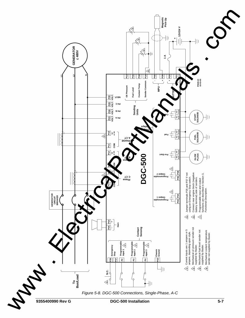
9355400990 Rev G DGC-500 Installation 5-7
P4P3P2P37
P35
ProgrammableOutput 2
ProgrammableOutput 1
Pre-Start
Fuel
Crank
GEN
ERA
TOR
CIR
CUI
TBR
EAKE
R
P17
P14
P11
STA
RT
SOLE
NOID
SOLE
NOID
FUEL
P36
P38
P33
P34
K1
N.O
.
Emer
genc
ySt
op
Prog
ram
mab
leIn
put 2
Prog
ram
mab
leIn
put 3
Chas
sis
Gro
und
Con
tact
Sens
ing
OutputRelays
CO
M1A or 5
A
PhaseC CT
B CTPhase
CO
M
A CTPHASE
CO
M
PH A
PH B
PH C
Oil
Pres
sure
Fuel
Lev
el
Coo
lant
Tem
p
Send
ing
Uni
ts
P40
P39
- +
MPU
P20
P21
BA
TTER
Y
12V/
24 V
+
GEN
ERA
TOR
-+
DG
C-5
00
ToB
us/L
oad N
.C.
480
V
P30
P23
P26
P29
VOLT
.VO
LT.
VOLT
.VO
LT.
NEUT.
Inpu
t 1Pr
ogra
mm
able
P002
8-10
03-0
3-05
3
2
4
P22
P24
P25 H
orn
1
-+
NL2L1
P15
P12
1A or 5
A
P10
1A or 5
A
1
PLU
GS
GLO
W
Send
er C
omm
on
P13
P16
P18
P19
6
K1
Com
K2
N.O
.K
2C
omK
5N.
O.
K5
Com
Mag
netic
Pick
-Up
1 A
5
77
7 7 7
6 7
Jum
per t
erm
inal
s P
35 a
nd P
37 if
not
usin
g an
Em
erge
ncy
Sto
p sw
itch.
Con
nect
nea
r en
gine
blo
ck (n
egat
ive
batte
ry te
rmin
al) s
ide
of s
ende
rs.
Pro
gram
mab
le in
put a
nd o
utpu
tfu
nctio
ns a
re d
escr
ibed
in S
ectio
n 3,
Func
tiona
l Des
crip
tion.
5C
urre
nt in
puts
are
1 a
mpe
re o
r 5am
pere
, dep
endi
ng u
pon
styl
e.M
echa
nica
l oil
pres
sure
sen
der n
otsu
pplie
d by
Bas
ler.
Mec
hani
cal f
uel l
evel
sen
der
not
supp
lied
by B
asle
r.M
echa
nica
l coo
lant
tem
pera
ture
send
er n
ot s
uppl
ied
by B
asle
r.
1 2 3 4
Figure 5-8. DGC-500 Connections, Single-Phase, A-C
www . El
ectric
alPar
tMan
uals
. com
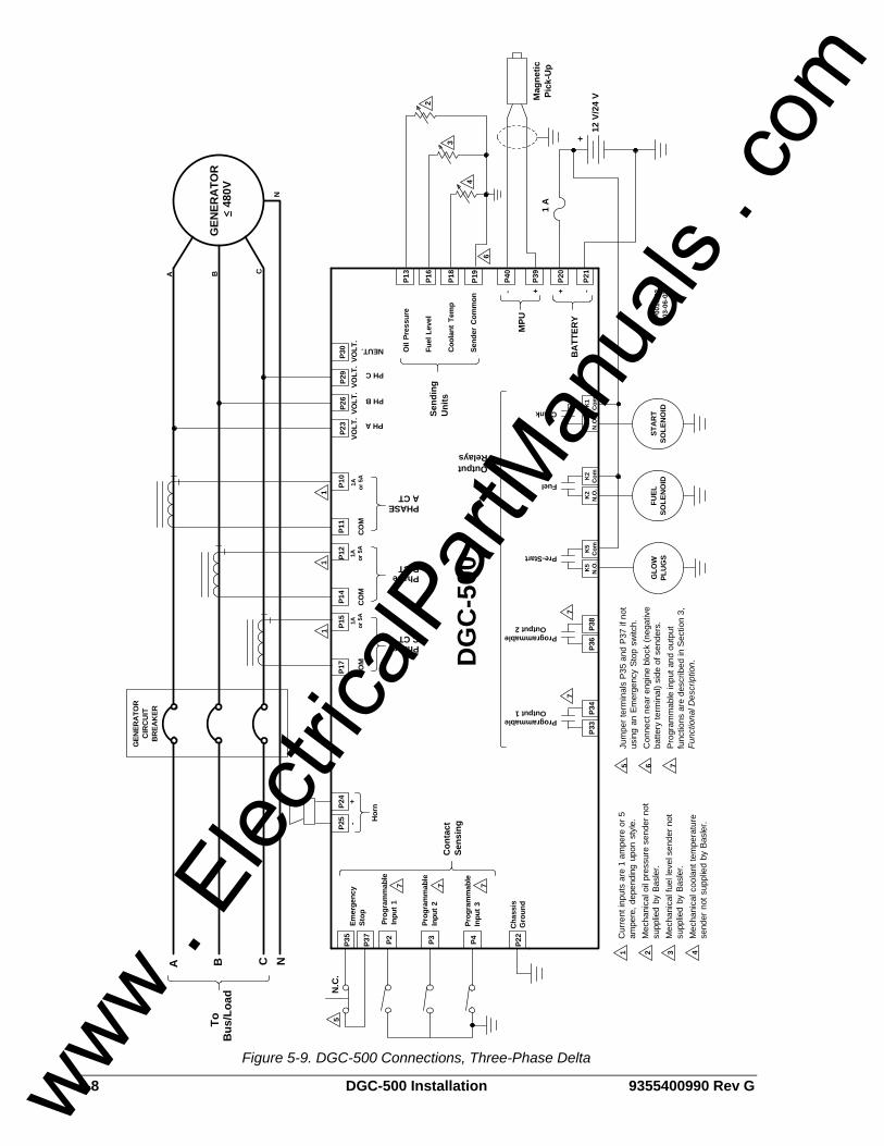
5-8 DGC-500 Installation 9355400990 Rev G
P4P3P2P37
P35
ProgrammableOutput 2
ProgrammableOutput 1
Pre-Start
Fuel
Crank
GEN
ERA
TOR
CIR
CU
ITB
REA
KER
P17
P14
P11
STA
RT
SOLE
NO
IDSO
LEN
OID
FUEL
P36
P38
P33
P34
K1
N.O
.
Emer
genc
ySt
op
Prog
ram
mab
leIn
put 2
Prog
ram
mab
leIn
put 3
Cha
ssis
Gro
und
Con
tact
Sens
ing
OutputRelays
CO
M1A or 5
A
PhaseC CT
B CTPhase
CO
M
A CTPHASE
CO
M
PH A
PH B
PH C
Oil
Pres
sure
Fuel
Lev
el
Coo
lant
Tem
p
Send
ing
Uni
ts
P40
P39
- +
MPU
P20
P21
BA
TTER
Y+
GEN
ERA
TOR
-+
DG
C-5
00
ToB
us/L
oad N
.C.
480
V
P30
P23
P26
P29
VOLT
.VO
LT.
VOLT
.VO
LT.
NEUT.
5
Inpu
t 1Pr
ogra
mm
able
P001
3-02
03-0
6-02
P22
P24
P25 H
orn
1
-+
CBA
P15
P12
1A or 5
A
P10
1A or 5
A
PLU
GS
GLO
W
Send
er C
omm
on
P13
P16
P18
P19
K1
Com
K2
N.O
.K
2C
omK
5N
.O.
K5
Com
11
N
A B C N
12 V
/24
V
3
2
4
6
Mag
netic
Pick
-Up
1 A
77
7 7 7
6 7
Jum
per t
erm
inal
s P
35 a
nd P
37 if
not
usin
g an
Em
erge
ncy
Stop
sw
itch.
Con
nect
nea
r eng
ine
bloc
k (n
egat
ive
batte
ry te
rmin
al) s
ide
of s
ende
rs.
Pro
gram
mab
le in
put a
nd o
utpu
tfu
nctio
ns a
re d
escr
ibed
in S
ectio
n 3,
Func
tiona
l Des
crip
tion.
5C
urre
nt in
puts
are
1 a
mpe
re o
r 5am
pere
, dep
endi
ng u
pon
styl
e.M
echa
nica
l oil
pres
sure
sen
der n
otsu
pplie
d by
Bas
ler.
Mec
hani
cal f
uel l
evel
sen
der n
otsu
pplie
d by
Bas
ler.
Mec
hani
cal c
oola
nt te
mpe
ratu
rese
nder
not
sup
plie
d b y
Bas
ler.
1 2 3 4
Figure 5-9. DGC-500 Connections, Three-Phase Delta
www . El
ectric
alPar
tMan
uals
. com
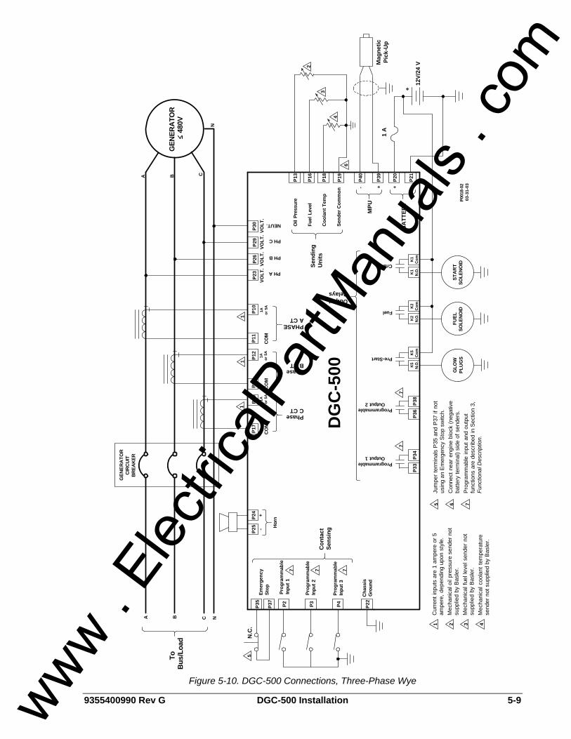
9355400990 Rev G DGC-500 Installation 5-9
P4P3P2P37
P35
ProgrammableOutput 2
ProgrammableOutput 1
Pre-Start
Fuel
Crank
GEN
ERA
TOR
CIR
CUI
TBR
EAKE
R
P17
P14
P11
STA
RT
SOLE
NOID
SOLE
NOID
FUEL
P36
P38
P33
P34
K1
N.O
.
Emer
genc
ySt
op
Prog
ram
mab
leIn
put 2
Prog
ram
mab
leIn
put 3
Chas
sis
Gro
und
Con
tact
Sens
ing
OutputRelays
CO
M1A or 5
A
PhaseC CT
B CTPhase
CO
M
A CTPHASE
CO
M
PH A
PH B
PH C
Oil
Pres
sure
Fuel
Lev
el
Coo
lant
Tem
p
Send
ing
Uni
ts
P40
P39
- +
MPU
P20
P21
BA
TTER
Y
12V/
24 V
+
GEN
ERA
TOR
-+
DG
C-5
00
ToB
us/L
oad N
.C.
480
V
P30
P23
P26
P29
VOLT
.VO
LT.
VOLT
.VO
LT.
NEUT.
Inpu
t 1Pr
ogra
mm
able
P001
8-02
03-3
1-03
3
2
4
P22
P24
P25 H
orn
1
-+
CBA
P15
P12
1A or 5
A
P10
1A or 5
A
PLU
GS
GLO
W
Send
er C
omm
on
P13
P16
P18
P19
6
K1
Com
K2
N.O
.K
2C
omK
5N.
O.
K5
Com
Mag
netic
Pick
-Up
1 A
5
77
7 7 7
6 7
Jum
per t
erm
inal
s P
35 a
nd P
37 if
not
usin
g an
Em
erge
ncy
Sto
p sw
itch.
Con
nect
nea
r en
gine
blo
ck (n
egat
ive
batte
ry te
rmin
al) s
ide
of s
ende
rs.
Pro
gram
mab
le in
put a
nd o
utpu
tfu
nctio
ns a
re d
escr
ibed
in S
ectio
n 3,
Func
tiona
l Des
crip
tion.
5C
urre
nt in
puts
are
1 a
mpe
re o
r 5am
pere
, dep
endi
ng u
pon
styl
e.M
echa
nica
l oil
pres
sure
sen
der n
otsu
pplie
d by
Bas
ler.
Mec
hani
cal f
uel l
evel
sen
der
not
supp
lied
by B
asle
r.M
echa
nica
l coo
lant
tem
pera
ture
send
er n
ot s
uppl
ied
by B
asle
r.
1 2 3 4
NNCBA
11
Figure 5-10. DGC-500 Connections, Three-Phase Wye
www . El
ectric
alPar
tMan
uals
. com
5-10 DGC-500 Installation 9355400990 Rev G
Volvo Penta EDC III Applications Engines equipped with Volvo Penta EDC III controllers can receive engine control commands (such as start and stop) from the DGC-500 through the SAE J1939 communication interface. To invoke this feature, the EDC III must receive a J1939 message containing engine control information within one second of waking (exiting sleep mode). If the EDC III does not receive an engine control message within the prescribed time, it will enter the stand-alone mode and ignore any J1939 control messages. If this occurs, the EDC III must be forced back into sleep mode by pressing the auxiliary stop pushbutton on the engine or by momentarily disconnecting EDC power. The interconnection diagrams of Figures 5-11 through 5-14 illustrate the DGC-500 and EDC III connections that allow the DGC-500 to awaken the EDC III and start the engine, or simply acquire engine status information. Wake-up of the EDC III is initiated by using the DGC-500 Fuel output contacts to apply battery power to the EDC. To stop the engine, the DGC-500 issues a sleep command through the J1939 interface to the EDC III and opens the Fuel output contacts. This causes the EDC to stop the engine and enter the sleep mode. In order for the DGC-500 to communicate with the EDC III, two DGC-500 settings must be changed from their default values. • The J1939 address of the DGC-500 must be set at 17 • The engine start/stop configuration setting must be set for Volvo Penta
Both settings are configured on the System Settings screen of BESTCOMS. Section 4, BESTCOMS Software has information about adjusting DGC-500 settings through BESTCOMS.
www . El
ectric
alPar
tMan
uals
. com
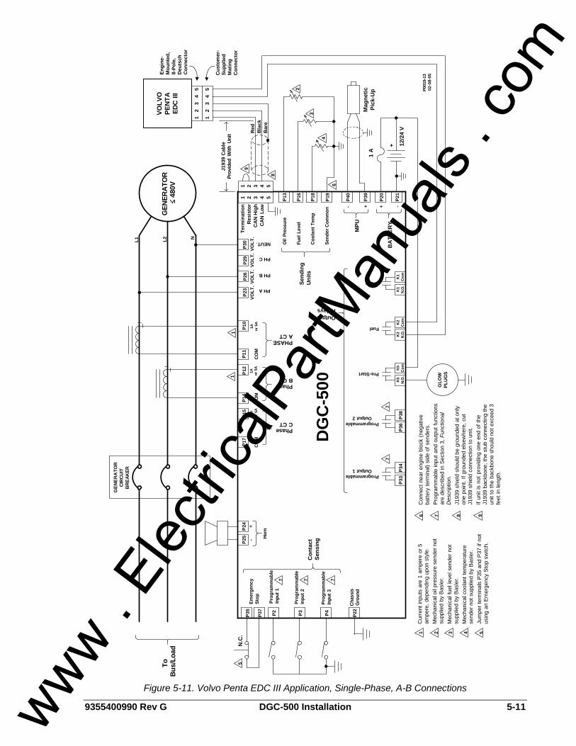
9355400990 Rev G DGC-500 Installation 5-11
1 2
3
4
5
P4P3P2P37
P35
ProgrammableOutput 2
ProgrammableOutput 1
Pre-Start
GEN
ERA
TOR
CIR
CUIT
BRE
AKER
P17
P14
P11
P36
P38
P33
P34
Emer
genc
ySt
op
Prog
ram
mab
leIn
put 2
Prog
ram
mab
leIn
put 3
Chas
sis
Gro
und
Con
tact
Sens
ing
OutputRelays
COM
1A or 5
A
PhaseC CT
B CTPhase
COM
A CTPHASE
COM
PH A
PH B
PH C
Oil
Pres
sure
Fuel
Lev
el
Coo
lant
Tem
p
Send
ing
Uni
ts
P40
P39
- +
MPU
P20
P21
BA
TTER
Y
12/2
4 V
-+
DG
C-5
00
ToB
us/L
oad N
.C.
P30
P23
P26
P29
VOLT
.VO
LT.
VOLT
.VO
LT.
NEUT.
Inpu
t 1Pr
ogra
mm
able
P001
9-13
02-0
8-05
3
2
4
P22
P24
P25 Ho
rn
1
-+
P15
P12
1A or 5
A
P10
1A or 5
A
1
Send
er C
omm
on
P13
P16
P18
P19
6
Mag
netic
Pick
-Up
1 A
5
77
7 7 7
6 7
Con
nect
nea
r eng
ine
bloc
k (n
egat
ive
batte
ry te
rmin
al) s
ide
of s
ende
rs.
Prog
ram
mab
le in
put a
nd o
utpu
t fun
ctio
nsar
e de
scrib
ed in
Sec
tion
3, F
unct
iona
lD
escr
iptio
n.J1
939
shie
ld s
houl
d be
gro
unde
d at
onl
yon
e po
int.
If gr
ound
ed e
lsew
here
, cut
J193
9 sh
ield
con
nect
ion
to u
nit.
If un
it is
not
pro
vidi
ng o
ne e
nd o
f the
J193
9 ba
ckbo
ne, t
he s
tub
conn
ectin
g th
eun
it to
the
back
bone
sho
uld
not e
xcee
d 3
feet
in le
ngth
.
5
Cur
rent
inpu
ts a
re 1
am
pere
or 5
ampe
re, d
epen
ding
upo
n st
yle.
Mec
hani
cal o
il pr
essu
re s
ende
r not
supp
lied
by B
asle
r.M
echa
nica
l fue
l lev
el s
ende
r no
tsu
pplie
d by
Bas
ler.
Mec
hani
cal c
oola
nt te
mpe
ratu
rese
nder
not
sup
plie
d by
Bas
ler.
Jum
per t
erm
inal
s P3
5 an
d P3
7 if
not
usin
g an
Em
erge
ncy
Stop
sw
itch.
2 3 4
1 2 3 4 5
1 2 3 4 5
Term
inat
ion
Res
isto
rC
AN
Hig
hCA
N Lo
w
VOLV
OPE
NTA
EDC
III
GEN
ERA
TOR
480
V
NL2L1
1 2
3
4
5
Engi
ne-
Mou
nted
,8-
Pole
,D
euts
chC
onne
ctor
Cus
tom
er-
Supp
lied
Mat
ing
Con
nect
or
Red
Bla
ckB
are
J193
9 C
able
Prov
ided
With
Uni
t
8
9
Fuel
Crank
K1
N.O
.
PLU
GS
GLO
W
K1
Com
K2
N.O
.K
2C
omK
5N
.O.
K5
Com
+
1
8 9
Figure 5-11. Volvo Penta EDC III Application, Single-Phase, A-B Connections
www . El
ectric
alPar
tMan
uals
. com
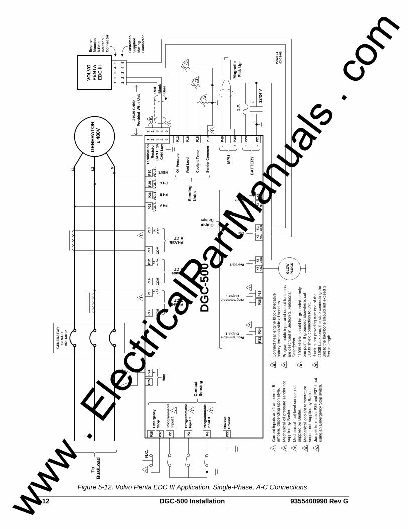
5-12 DGC-500 Installation 9355400990 Rev G
1 2
3
4
5
P4P3P2P37
P35
ProgrammableOutput 2
ProgrammableOutput 1
Pre-Start
GEN
ERA
TOR
CIR
CUIT
BRE
AKER
P17
P14
P11
P36
P38
P33
P34
Emer
genc
ySt
op
Prog
ram
mab
leIn
put 2
Prog
ram
mab
leIn
put 3
Chas
sis
Gro
und
Con
tact
Sens
ing
OutputRelays
COM
1A or 5
A
PhaseC CT
B CTPhase
COM
A CTPHASE
COM
PH A
PH B
PH C
Oil
Pres
sure
Fuel
Lev
el
Coo
lant
Tem
p
Send
ing
Uni
ts
P40
P39
- +
MPU
P20
P21
BA
TTER
Y
12/2
4 V
-+
DG
C-5
00
ToB
us/L
oad N
.C.
P30
P23
P26
P29
VOLT
.VO
LT.
VOLT
.VO
LT.
NEUT.
Inpu
t 1Pr
ogra
mm
able
P002
8-11
03-0
3-05
3
2
4
P22
P24
P25 Ho
rn
1
-+
P15
P12
1A or 5
A
P10
1A or 5
A
1
Send
er C
omm
on
P13
P16
P18
P19
6
Mag
netic
Pick
-Up
1 A
5
77
7 7 7
6 7
Con
nect
nea
r eng
ine
bloc
k (n
egat
ive
batte
ry te
rmin
al) s
ide
of s
ende
rs.
Prog
ram
mab
le in
put a
nd o
utpu
t fun
ctio
nsar
e de
scrib
ed in
Sec
tion
3, F
unct
iona
lD
escr
iptio
n.J1
939
shie
ld s
houl
d be
gro
unde
d at
onl
yon
e po
int.
If gr
ound
ed e
lsew
here
, cut
J193
9 sh
ield
con
nect
ion
to u
nit.
If un
it is
not
pro
vidi
ng o
ne e
nd o
f the
J193
9 ba
ckbo
ne, t
he s
tub
conn
ectin
g th
eun
it to
the
back
bone
sho
uld
not e
xcee
d 3
feet
in le
ngth
.
5
Cur
rent
inpu
ts a
re 1
am
pere
or 5
ampe
re, d
epen
ding
upo
n st
yle.
Mec
hani
cal o
il pr
essu
re s
ende
r not
supp
lied
by B
asle
r.M
echa
nica
l fue
l lev
el s
ende
r no
tsu
pplie
d by
Bas
ler.
Mec
hani
cal c
oola
nt te
mpe
ratu
rese
nder
not
sup
plie
d by
Bas
ler.
Jum
per t
erm
inal
s P3
5 an
d P3
7 if
not
usin
g an
Em
erge
ncy
Stop
sw
itch.
2 3 4
1 2 3 4 5
1 2 3 4 5
Term
inat
ion
Res
isto
rC
AN
Hig
hCA
N Lo
w
VOLV
OPE
NTA
EDC
III
GEN
ERA
TOR
480
V
NL2L1
1 2
3
4
5
Engi
ne-
Mou
nted
,8-
Pole
,D
euts
chC
onne
ctor
Cus
tom
er-
Supp
lied
Mat
ing
Con
nect
or
Red
Bla
ckB
are
J193
9 C
able
Prov
ided
With
Uni
t
8
9
Fuel
Crank
K1
N.O
.
PLU
GS
GLO
W
K1
Com
K2
N.O
.K
2C
omK
5N
.O.
K5
Com
+
1
8 9
Figure 5-12. Volvo Penta EDC III Application, Single-Phase, A-C Connections
www . El
ectric
alPar
tMan
uals
. com
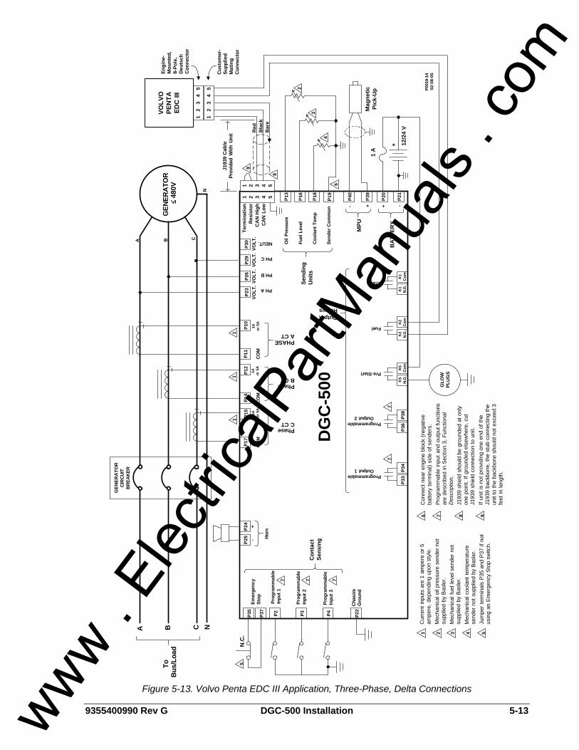
9355400990 Rev G DGC-500 Installation 5-13
1 2
3
4
5
P4P3P2P37
P35
ProgrammableOutput 2
ProgrammableOutput 1
Pre-Start
P17
P14
P11
P36
P38
P33
P34
Emer
genc
ySt
op
Prog
ram
mab
leIn
put 2
Prog
ram
mab
leIn
put 3
Chas
sis
Gro
und
Con
tact
Sens
ing
OutputRelays
CO
M1A or 5
A
PhaseC CT
B CTPhase
CO
M
A CTPHASE
CO
M
PH A
PH B
PH C
Oil
Pres
sure
Fuel
Lev
el
Coo
lant
Tem
p
Send
ing
Uni
ts
P40
P39
- +M
PU
P20
P21
BA
TTER
Y
12/2
4 V
-+
DG
C-5
00
N.C
.P3
0P2
3P2
6P2
9VO
LT.
VOLT
.VO
LT.
VOLT
.
NEUT.
Inpu
t 1Pr
ogra
mm
able
P001
9-14
02-0
8-05
3
2
4
P22
P24
P25 Ho
rn
-+
P15
P12
1A or 5
A
P10
1A or 5
A
Send
er C
omm
on
P13
P16
P18
P19
6
Mag
netic
Pick
-Up
1 A
5
77
7 7 7
6 7
Con
nect
nea
r eng
ine
bloc
k (n
egat
ive
batte
ry te
rmin
al) s
ide
of s
ende
rs.
Prog
ram
mab
le in
put a
nd o
utpu
t fun
ctio
nsar
e de
scrib
ed in
Sec
tion
3, F
unct
iona
lD
escr
iptio
n.J1
939
shie
ld s
houl
d be
gro
unde
d at
onl
yon
e po
int.
If gr
ound
ed e
lsew
here
, cut
J193
9 sh
ield
con
nect
ion
to u
nit.
If un
it is
not
pro
vidi
ng o
ne e
nd o
f the
J193
9 ba
ckbo
ne, t
he s
tub
conn
ectin
g th
eun
it to
the
back
bone
sho
uld
not e
xcee
d 3
feet
in le
ngth
.
5
Cur
rent
inpu
ts a
re 1
am
pere
or 5
ampe
re, d
epen
ding
upo
n st
yle.
Mec
hani
cal o
il pr
essu
re s
ende
r not
supp
lied
by B
asle
r.M
echa
nica
l fue
l lev
el s
ende
r not
supp
lied
by B
asle
r.M
echa
nica
l coo
lant
tem
pera
ture
send
er n
ot s
uppl
ied
by B
asle
r.Ju
mpe
r ter
min
als
P35
and
P37
if no
tus
ing
an E
mer
genc
y St
op s
witc
h.
2 3 4
1 2 3 4 5
1 2 3 4 5
Term
inat
ion
Res
isto
rC
AN
Hig
hCA
N Lo
w
VOLV
OPE
NTA
EDC
III
1 2
3
4
5
Engi
ne-
Mou
nted
,8-
Pole
,D
euts
chC
onne
ctor
Cus
tom
er-
Supp
lied
Mat
ing
Con
nect
or
Red
Bla
ckB
are
J193
9 C
able
Prov
ided
With
Uni
t
8
9
Fuel
Crank
K1
N.O
.
PLU
GS
GLO
W
K1
Com
K2
N.O
.K
2C
omK
5N
.O.
K5
Com
+
1
8 9
GEN
ERA
TOR
CIR
CUIT
BREA
KER
ToB
us/L
oad
11
1
A B C N
GEN
ERA
TOR
480
V
CBA
N
Figure 5-13. Volvo Penta EDC III Application, Three-Phase, Delta Connections
www . El
ectric
alPar
tMan
uals
. com
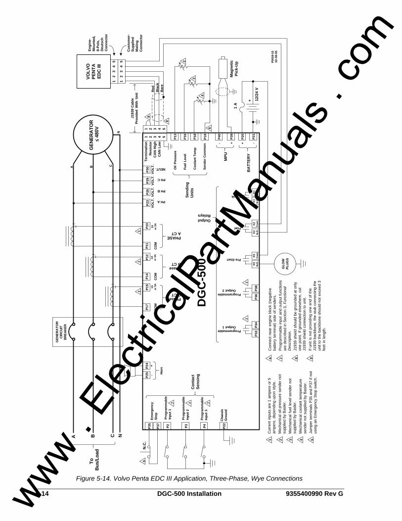
5-14 DGC-500 Installation 9355400990 Rev G
1 2
3
4
5
P4P3P2P37
P35
ProgrammableOutput 2
ProgrammableOutput 1
Pre-Start
P17
P14
P11
P36
P38
P33
P34
Emer
genc
ySt
op
Prog
ram
mab
leIn
put 2
Prog
ram
mab
leIn
put 3
Chas
sis
Gro
und
Con
tact
Sens
ing
OutputRelays
CO
M1A or 5
A
PhaseC CT
B CTPhase
CO
M
A CTPHASE
CO
M
PH A
PH B
PH C
Oil
Pres
sure
Fuel
Lev
el
Coo
lant
Tem
p
Send
ing
Uni
ts
P40
P39
- +M
PU
P20
P21
BA
TTER
Y
12/2
4 V
-+
DG
C-5
00
N.C
.P3
0P2
3P2
6P2
9VO
LT.
VOLT
.VO
LT.
VOLT
.
NEUT.
Inpu
t 1Pr
ogra
mm
able
P001
9-15
02-0
8-05
3
2
4
P22
P24
P25 Ho
rn
-+
P15
P12
1A or 5
A
P10
1A or 5
A
Send
er C
omm
on
P13
P16
P18
P19
6
Mag
netic
Pick
-Up
1 A
5
77
7 7 7
6 7
Con
nect
nea
r eng
ine
bloc
k (n
egat
ive
batte
ry te
rmin
al) s
ide
of s
ende
rs.
Prog
ram
mab
le in
put a
nd o
utpu
t fun
ctio
nsar
e de
scrib
ed in
Sec
tion
3, F
unct
iona
lD
escr
iptio
n.J1
939
shie
ld s
houl
d be
gro
unde
d at
onl
yon
e po
int.
If gr
ound
ed e
lsew
here
, cut
J193
9 sh
ield
con
nect
ion
to u
nit.
If un
it is
not
pro
vidi
ng o
ne e
nd o
f the
J193
9 ba
ckbo
ne, t
he s
tub
conn
ectin
g th
eun
it to
the
back
bone
sho
uld
not e
xcee
d 3
feet
in le
ngth
.
5
Cur
rent
inpu
ts a
re 1
am
pere
or 5
ampe
re, d
epen
ding
upo
n st
yle.
Mec
hani
cal o
il pr
essu
re s
ende
r not
supp
lied
by B
asle
r.M
echa
nica
l fue
l lev
el s
ende
r not
supp
lied
by B
asle
r.M
echa
nica
l coo
lant
tem
pera
ture
send
er n
ot s
uppl
ied
by B
asle
r.Ju
mpe
r ter
min
als
P35
and
P37
if no
tus
ing
an E
mer
genc
y St
op s
witc
h.
2 3 4
1 2 3 4 5
1 2 3 4 5
Term
inat
ion
Res
isto
rC
AN
Hig
hCA
N Lo
w
VOLV
OPE
NTA
EDC
III
1 2
3
4
5
Engi
ne-
Mou
nted
,8-
Pole
,D
euts
chC
onne
ctor
Cus
tom
er-
Supp
lied
Mat
ing
Con
nect
or
Red
Bla
ckB
are
J193
9 C
able
Prov
ided
With
Uni
t
8
9
Fuel
Crank
K1
N.O
.
PLU
GS
GLO
W
K1
Com
K2
N.O
.K
2C
omK
5N
.O.
K5
Com
+
1
8 9
GEN
ERA
TOR
CIR
CUIT
BREA
KER
ToB
us/L
oad
11
1
A B C N
GEN
ERA
TOR
480
V
CBA
N
Figure 5-14. Volvo Penta EDC III Application, Three-Phase, Wye Connections
www . El
ectric
alPar
tMan
uals
. com
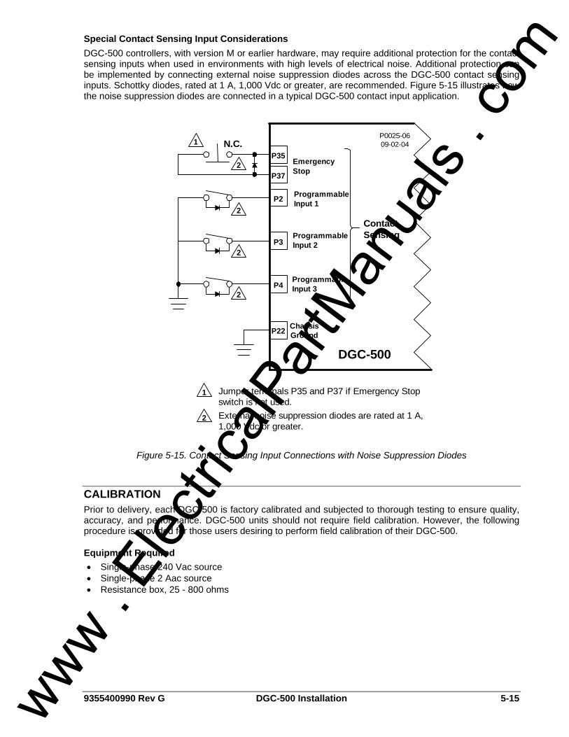
9355400990 Rev G DGC-500 Installation 5-15
Special Contact Sensing Input Considerations DGC-500 controllers, with version M or earlier hardware, may require additional protection for the contact sensing inputs when used in environments with high levels of electrical noise. Additional protection can be implemented by connecting external noise suppression diodes across the DGC-500 contact sensing inputs. Schottky diodes, rated at 1 A, 1,000 Vdc or greater, are recommended. Figure 5-15 illustrates how the noise suppression diodes are connected in a typical DGC-500 contact input application.
P4
P3
P2
P37
P35EmergencyStop
ProgrammableInput 2
ProgrammableInput 3
ChassisGround
ContactSensing
N.C.
Input 1Programmable
P22
1
2
2
2
2
DGC-500
P0025-0609-02-04
Jumper terminals P35 and P37 if Emergency Stopswitch is not used.External noise suppression diodes are rated at 1 A,1,000 Vdc or greater.
1
2
Figure 5-15. Contact Sensing Input Connections with Noise Suppression Diodes
CALIBRATION Prior to delivery, each DGC-500 is factory calibrated and subjected to thorough testing to ensure quality, accuracy, and performance. DGC-500 units should not require field calibration. However, the following procedure is provided for those users desiring to perform field calibration of their DGC-500.
Equipment Required • Single-phase 240 Vac source • Single-phase 2 Aac source • Resistance box, 25 - 800 ohms
www . El
ectric
alPar
tMan
uals
. com
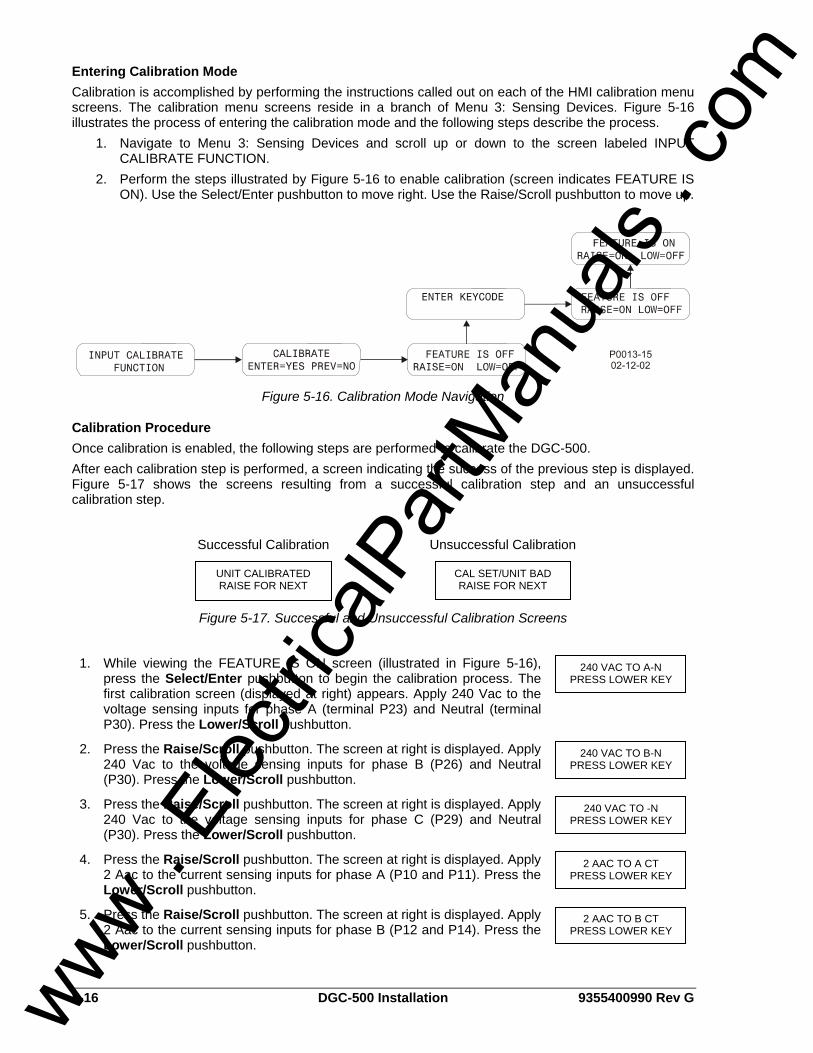
5-16 DGC-500 Installation 9355400990 Rev G
Entering Calibration Mode Calibration is accomplished by performing the instructions called out on each of the HMI calibration menu screens. The calibration menu screens reside in a branch of Menu 3: Sensing Devices. Figure 5-16 illustrates the process of entering the calibration mode and the following steps describe the process.
1. Navigate to Menu 3: Sensing Devices and scroll up or down to the screen labeled INPUT CALIBRATE FUNCTION.
2. Perform the steps illustrated by Figure 5-16 to enable calibration (screen indicates FEATURE IS ON). Use the Select/Enter pushbutton to move right. Use the Raise/Scroll pushbutton to move up.
Figure 5-16. Calibration Mode Navigation
Calibration Procedure Once calibration is enabled, the following steps are performed to calibrate the DGC-500. After each calibration step is performed, a screen indicating the success of the previous step is displayed. Figure 5-17 shows the screens resulting from a successful calibration step and an unsuccessful calibration step.
Successful Calibration Unsuccessful Calibration
Figure 5-17. Successful and Unsuccessful Calibration Screens
1. While viewing the FEATURE IS ON screen (illustrated in Figure 5-16), press the Select/Enter pushbutton to begin the calibration process. The first calibration screen (displayed at right) appears. Apply 240 Vac to the voltage sensing inputs for phase A (terminal P23) and Neutral (terminal P30). Press the Lower/Scroll pushbutton.
2. Press the Raise/Scroll pushbutton. The screen at right is displayed. Apply 240 Vac to the voltage sensing inputs for phase B (P26) and Neutral (P30). Press the Lower/Scroll pushbutton.
3. Press the Raise/Scroll pushbutton. The screen at right is displayed. Apply 240 Vac to the voltage sensing inputs for phase C (P29) and Neutral (P30). Press the Lower/Scroll pushbutton.
4. Press the Raise/Scroll pushbutton. The screen at right is displayed. Apply 2 Aac to the current sensing inputs for phase A (P10 and P11). Press the Lower/Scroll pushbutton.
5. Press the Raise/Scroll pushbutton. The screen at right is displayed. Apply 2 Aac to the current sensing inputs for phase B (P12 and P14). Press the Lower/Scroll pushbutton.
2 AAC TO B CT PRESS LOWER KEY
2 AAC TO A CT PRESS LOWER KEY
240 VAC TO -N PRESS LOWER KEY
240 VAC TO B-N PRESS LOWER KEY
240 VAC TO A-N PRESS LOWER KEY
CAL SET/UNIT BAD RAISE FOR NEXT
UNIT CALIBRATED RAISE FOR NEXT
www . El
ectric
alPar
tMan
uals
. com
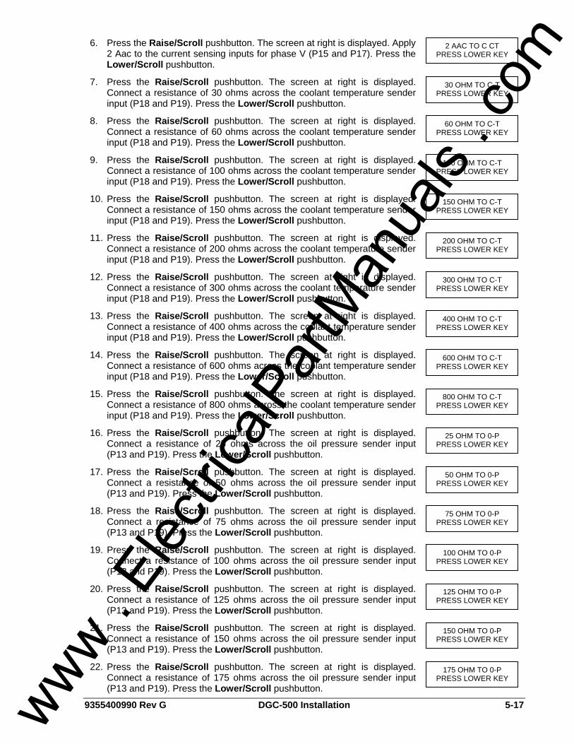
9355400990 Rev G DGC-500 Installation 5-17
6. Press the Raise/Scroll pushbutton. The screen at right is displayed. Apply 2 Aac to the current sensing inputs for phase V (P15 and P17). Press the Lower/Scroll pushbutton.
7. Press the Raise/Scroll pushbutton. The screen at right is displayed. Connect a resistance of 30 ohms across the coolant temperature sender input (P18 and P19). Press the Lower/Scroll pushbutton.
8. Press the Raise/Scroll pushbutton. The screen at right is displayed. Connect a resistance of 60 ohms across the coolant temperature sender input (P18 and P19). Press the Lower/Scroll pushbutton.
9. Press the Raise/Scroll pushbutton. The screen at right is displayed. Connect a resistance of 100 ohms across the coolant temperature sender input (P18 and P19). Press the Lower/Scroll pushbutton.
10. Press the Raise/Scroll pushbutton. The screen at right is displayed. Connect a resistance of 150 ohms across the coolant temperature sender input (P18 and P19). Press the Lower/Scroll pushbutton.
11. Press the Raise/Scroll pushbutton. The screen at right is displayed. Connect a resistance of 200 ohms across the coolant temperature sender input (P18 and P19). Press the Lower/Scroll pushbutton.
12. Press the Raise/Scroll pushbutton. The screen at right is displayed. Connect a resistance of 300 ohms across the coolant temperature sender input (P18 and P19). Press the Lower/Scroll pushbutton.
13. Press the Raise/Scroll pushbutton. The screen at right is displayed. Connect a resistance of 400 ohms across the coolant temperature sender input (P18 and P19). Press the Lower/Scroll pushbutton.
14. Press the Raise/Scroll pushbutton. The screen at right is displayed. Connect a resistance of 600 ohms across the coolant temperature sender input (P18 and P19). Press the Lower/Scroll pushbutton.
15. Press the Raise/Scroll pushbutton. The screen at right is displayed. Connect a resistance of 800 ohms across the coolant temperature sender input (P18 and P19). Press the Lower/Scroll pushbutton.
16. Press the Raise/Scroll pushbutton. The screen at right is displayed. Connect a resistance of 25 ohms across the oil pressure sender input (P13 and P19). Press the Lower/Scroll pushbutton.
17. Press the Raise/Scroll pushbutton. The screen at right is displayed. Connect a resistance of 50 ohms across the oil pressure sender input (P13 and P19). Press the Lower/Scroll pushbutton.
18. Press the Raise/Scroll pushbutton. The screen at right is displayed. Connect a resistance of 75 ohms across the oil pressure sender input (P13 and P19). Press the Lower/Scroll pushbutton.
19. Press the Raise/Scroll pushbutton. The screen at right is displayed. Connect a resistance of 100 ohms across the oil pressure sender input (P13 and P19). Press the Lower/Scroll pushbutton.
20. Press the Raise/Scroll pushbutton. The screen at right is displayed. Connect a resistance of 125 ohms across the oil pressure sender input (P13 and P19). Press the Lower/Scroll pushbutton.
21. Press the Raise/Scroll pushbutton. The screen at right is displayed. Connect a resistance of 150 ohms across the oil pressure sender input (P13 and P19). Press the Lower/Scroll pushbutton.
22. Press the Raise/Scroll pushbutton. The screen at right is displayed. Connect a resistance of 175 ohms across the oil pressure sender input (P13 and P19). Press the Lower/Scroll pushbutton.
175 OHM TO 0-P PRESS LOWER KEY
150 OHM TO 0-P PRESS LOWER KEY
125 OHM TO 0-P PRESS LOWER KEY
100 OHM TO 0-P PRESS LOWER KEY
75 OHM TO 0-P PRESS LOWER KEY
50 OHM TO 0-P PRESS LOWER KEY
25 OHM TO 0-P PRESS LOWER KEY
800 OHM TO C-T PRESS LOWER KEY
600 OHM TO C-T PRESS LOWER KEY
400 OHM TO C-T PRESS LOWER KEY
300 OHM TO C-T PRESS LOWER KEY
200 OHM TO C-T PRESS LOWER KEY
150 OHM TO C-T PRESS LOWER KEY
100 OHM TO C-T PRESS LOWER KEY
60 OHM TO C-T PRESS LOWER KEY
30 OHM TO C-T PRESS LOWER KEY
2 AAC TO C CT PRESS LOWER KEY
www . El
ectric
alPar
tMan
uals
. com
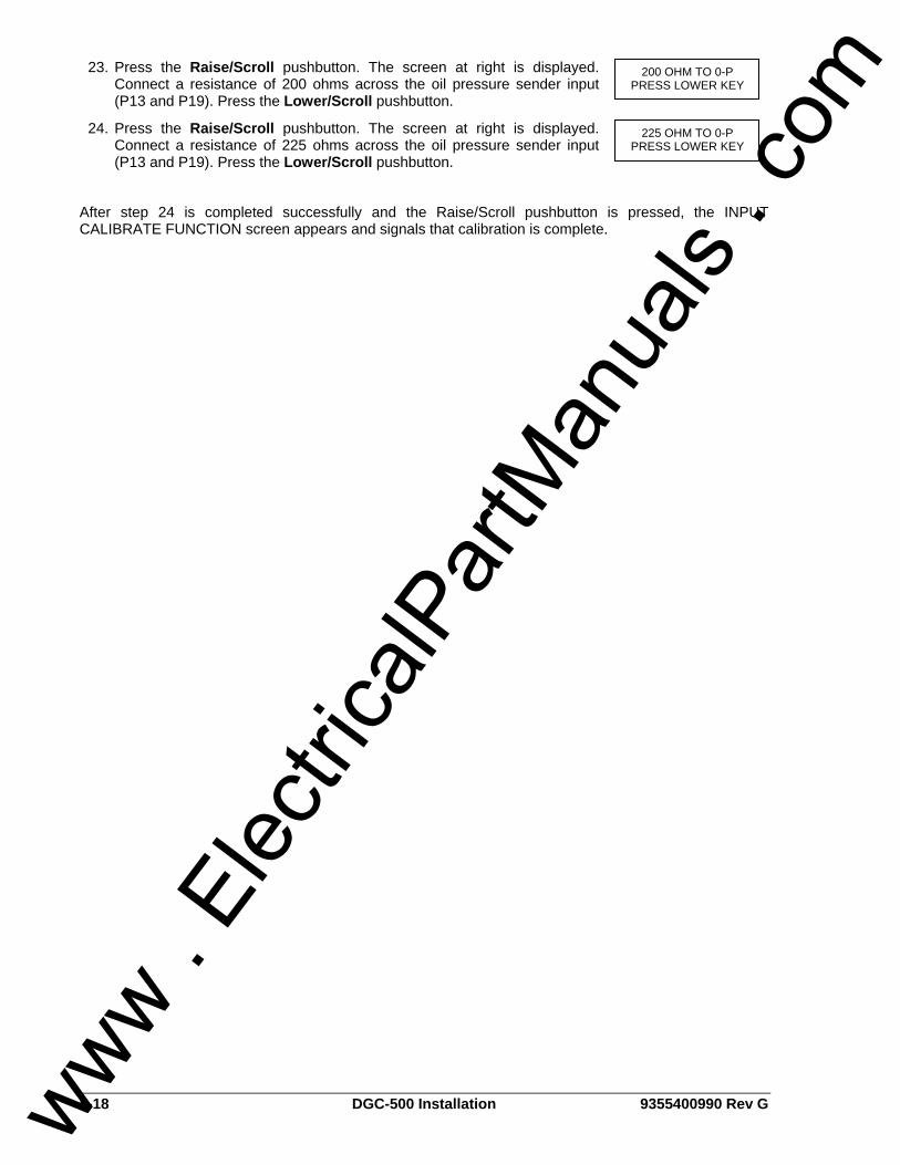
5-18 DGC-500 Installation 9355400990 Rev G
23. Press the Raise/Scroll pushbutton. The screen at right is displayed. Connect a resistance of 200 ohms across the oil pressure sender input (P13 and P19). Press the Lower/Scroll pushbutton.
24. Press the Raise/Scroll pushbutton. The screen at right is displayed. Connect a resistance of 225 ohms across the oil pressure sender input (P13 and P19). Press the Lower/Scroll pushbutton.
After step 24 is completed successfully and the Raise/Scroll pushbutton is pressed, the INPUT CALIBRATE FUNCTION screen appears and signals that calibration is complete.
225 OHM TO 0-P PRESS LOWER KEY
200 OHM TO 0-P PRESS LOWER KEY
www . El
ectric
alPar
tMan
uals
. com
9355400990 Rev G DGC-500 Maintenance and Troubleshooting i
SECTION 6 • MAINTENANCE AND TROUBLESHOOTING
TABLE OF CONTENTS SECTION 6 • MAINTENANCE AND TROUBLESHOOTING.................................................................... 6-1
PREVENTATIVE MAINTENANCE ........................................................................................................ 6-1 TROUBLESHOOTING........................................................................................................................... 6-1
Incorrect Display of Battery Voltage, Coolant Temperature, Oil Pressure, or Fuel Level.................. 6-1 Incorrect Display of Generator Voltage .............................................................................................. 6-1 Incorrect Measurement or Display of Generator Current................................................................... 6-1 Incorrect Display of Engine RPM ....................................................................................................... 6-1 Programmable Inputs Do Not Operate as Expected.......................................................................... 6-2 Programmable Outputs Do Not Operate as Expected....................................................................... 6-2 Communication Port Does Not Operate Properly .............................................................................. 6-2
www . El
ectric
alPar
tMan
uals
. com

ii DGC-500 Maintenance and Troubleshooting 9355400990 Rev G
This page intentionally left blank.
www . El
ectric
alPar
tMan
uals
. com
9355400990 Rev G DGC-500 Maintenance and Troubleshooting 6-1
SECTION 6 • MAINTENANCE AND TROUBLESHOOTING
PREVENTATIVE MAINTENANCE The only preventative maintenance required on the DGC-500 is to periodically check that the connections between the DGC-500 and the system are clean and tight. DGC-500 units are manufactured using state-of-the-art, surface-mount technology. As such, Basler Electric recommends that no repair procedures be attempted by anyone other than Basler Electric personnel.
TROUBLESHOOTING If you do not get the results that you expect from the DGC-500, first check the programmable settings for the appropriate function. Use the following troubleshooting procedures when difficulties are encountered in the operation of your genset control system.
Incorrect Display of Battery Voltage, Coolant Temperature, Oil Pressure, or Fuel Level Step 1. Verify that all wiring is properly connected. Refer to Figures 5-7 through 5-14. Step 2. Confirm that the SENDER COMM terminal (P19) is connected to the negative battery terminal
and the engine-block side of the senders. Current from other devices sharing this connection can cause erroneous readings.
Step 3. If the displayed battery voltage is incorrect, ensure that the proper voltage is present between the BATT+ terminal (P20) and the SENDER COMM terminal (P19).
Step 4. Verify that the correct senders are being used. Step 5. Verify that the correct sender curves are being used. Step 6. Ensure that the senders are operating properly.
Incorrect Display of Generator Voltage Step 1. Verify that all wiring is properly connected. Refer to Figures 5-7 through 5-14. Step 2. Ensure that the proper voltage is present at the DGC-500 voltage sensing inputs (P23, P26,
P29, and P30). Step 3. Verify that the voltage transformer ratio and sensing configuration is correct. Step 4. Confirm that the voltage sensing transformers are correct and properly installed.
Incorrect Measurement or Display of Generator Current Step 1. Verify that all wiring is properly connected. Refer to Figures 5-7 through 5-14. Step 2. Ensure that the proper current is present at the DGC-500 current sensing inputs (P10 - P17). Step 3. Verify that the current sensing transformer ratios are correct. Step 4. Confirm that the current sensing transformers are correct and properly installed.
Incorrect Display of Engine RPM Step 1. Verify that all wiring is properly connected. Refer to Figures 5-7 through 5-14. Step 2. Verify that the flywheel teeth setting is correct. Step 3. Confirm the nominal frequency setting. Step 4. Verify that the prime mover governor is operating properly. Step 5. Verify that the measured frequency of the voltage at the MPU input (P39 and P40) is correct. Step 6. If the MPU is shared with the governor, verify that the polarity of the MPU input to the governor
matches the polarity of the MPU input to the DGC-500.
www . El
ectric
alPar
tMan
uals
. com
6-2 DGC-500 Maintenance and Troubleshooting 9355400990 Rev G
Programmable Inputs Do Not Operate as Expected Step 1. Verify that all wiring is properly connected. Refer to Figures 5-7 through 5-14. Step 2. Confirm that the inputs are programmed properly. Step 3. Ensure that the input at the DGC-500 is actually connected to the BATT– terminal (P21).
Programmable Outputs Do Not Operate as Expected Step 1. Verify that all wiring is properly connected. Refer to Figures 5-7 through 5-14. Step 2. Confirm that the outputs are programmed properly.
Communication Port Does Not Operate Properly Step 1. Verify that the proper port of your computer is being used. Step 2. Confirm that the correct baud rate is being used. Step 3. Verify that the connection between the computer and the DGC-500 is correct. Ensure that a
straight-through serial cable is being used.
www . El
ectric
alPar
tMan
uals
. com
9355400990 Rev G DGC-500 Time Overcurrent Characteristic Curves i
APPENDIX A • TIME OVERCURRENT CHARACTERISTIC CURVES
TABLE OF CONTENTS APPENDIX A • TIME OVERCURRENT CHARACTERISTIC CURVES ...................................................A-1
INTRODUCTION ...................................................................................................................................A-1 CURVE SPECIFICATIONS ...................................................................................................................A-1 TIME OVERCURRENT CHARACTERISTIC CURVE GRAPHS...........................................................A-2
Time Dial Setting Cross-Reference....................................................................................................A-3
Figures Figure A-1. Time Characteristic Curve S, S1, Short Inverse (Similar to ABB CO-2) ................................A-5 Figure A-2. Time Characteristic Curve S2, Short Inverse (Similar To GE IAC-55)...................................A-6 Figure A-3. Time Characteristic Curve L, L1, Long Inverse (Similar to ABB CO-5) .................................A-7 Figure A-4. Time Characteristic Curve L2, Long Inverse (Similar To GE IAC-66)....................................A-8 Figure A-5. Time Characteristic Curve D, Definite Time (Similar To ABB CO-6) .....................................A-9 Figure A-6. Time Characteristic Curve M, Moderately Inverse (Similar to ABB CO-7)...........................A-10 Figure A-7. Time Characteristic Curve I, I1, Inverse Time (Similar to ABB CO-8) .................................A-11 Figure A-8. Time Characteristic Curve I2, Inverse Time (Similar to GE IAC-51)....................................A-12 Figure A-9. Time Characteristic Curve V, V1, Very Inverse (Similar to ABB CO-9) ...............................A-13 Figure A-10. Time Characteristic Curve V2, Very Inverse (Similar to GE IAC-53) .................................A-14 Figure A-11. Time Characteristic Curve E, E1, Extremely Inverse (Similar to ABB CO-11)...................A-15 Figure A-12. Time Characteristic Curve E2, Extremely Inverse (Similar to GE IAC-77) ........................A-16 Figure A-13. Time Characteristic Curve A, Standard Inverse.................................................................A-17 Figure A-14. Time Characteristic Curve B, Very Inverse ........................................................................A-18 Figure A-15. Time Characteristic Curve C, Extremely Inverse ...............................................................A-19 Figure A-16. Time Characteristic Curve G, Long Time Inverse ..............................................................A-20
Tables Table A-1. Time Characteristic Curve Constants......................................................................................A-2 Table A-2. Characteristic Curve Cross-Reference....................................................................................A-3 Table A-3 .Time Dial Setting Cross-Reference .........................................................................................A-4
www . El
ectric
alPar
tMan
uals
. com
ii DGC-500 Time Overcurrent Characteristic Curves 9355400990 Rev G
This page intentionally left blank.
www . El
ectric
alPar
tMan
uals
. com
9355400990 Rev G DGC-500 Time Overcurrent Characteristic Curves A-1
APPENDIX A • TIME OVERCURRENT CHARACTERISTIC CURVES
INTRODUCTION The inverse time overcurrent characteristic curves provided by the DGC-500 (style xxx1 only) closely emulate most of the common electromechanical, induction-disk, overcurrent relays sold in North America.
CURVE SPECIFICATIONS Timing Accuracy: Within ±500 milliseconds of indicated operating
point. Sixteen inverse time functions and one fixed time
function can be selected. Characteristic curves for the inverse and definite time functions are defined by the following equation:
KDBCM
DATNT +•+−
•= Equation A-1
TT = Time to trip when M ≥ 1 TR = Time to reset if relay is set for integrating
reset when M < 1. Otherwise, reset is 50 milliseconds or less
D = TIME DIAL setting (0.0 to 9.9) M = Multiple of PICKUP setting (0 to 40) A, B, C, N, K = Constants for the particular curve This equation complies with IEEE Standard
C37.112-1996. Table A-1 lists time characteristic curve
constants. See Figures A-1 through A-16 for graphs of the characteristics.
www . El
ectric
alPar
tMan
uals
. com
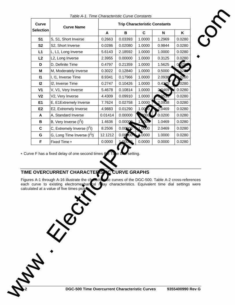
A-2 DGC-500 Time Overcurrent Characteristic Curves 9355400990 Rev G
Table A-1. Time Characteristic Curve Constants
Trip Characteristic Constants Curve Selection
Curve Name A B C N K
S1 S, S1, Short Inverse 0.2663 0.03393 1.0000 1.2969 0.0280 S2 S2, Short Inverse 0.0286 0.02080 1.0000 0.9844 0.0280 L1 L, L1, Long Inverse 5.6143 2.18592 1.0000 1.0000 0.0280 L2 L2, Long Inverse 2.3955 0.00000 1.0000 0.3125 0.0280 D D, Definite Time 0.4797 0.21359 1.0000 1.5625 0.0280 M M, Moderately Inverse 0.3022 0.12840 1.0000 0.5000 0.0280 I1 I, I1, Inverse Time 8.9341 0.17966 1.0000 2.0938 0.0280 I2 I2, Inverse Time 0.2747 0.10426 1.0000 0.4375 0.0280 V1 V, V1, Very Inverse 5.4678 0.10814 1.0000 2.0469 0.0280 V2 V2, Very Inverse 4.4309 0.09910 1.0000 1.9531 0.0280 E1 E, E1Extremely Inverse 7.7624 0.02758 1.0000 2.0938 0.0280 E2 E2, Extremely Inverse 4.9883 0.01290 1.0000 2.0469 0.0280 A A, Standard Inverse 0.01414 0.00000 1.0000 0.0200 0.0280
B B, Very Inverse (I2t) 1.4636 0.00000 1.0000 1.0469 0.0280
C C, Extremely Inverse (I2t) 8.2506 0.00000 1.0000 2.0469 0.0280
G G, Long Time Inverse (I2t) 12.1212 0.00000 1.0000 1.0000 0.0280
F Fixed Time ∗ 0.0000 1.00000 0.0000 0.0000 0.0280 ∗ Curve F has a fixed delay of one second times the Time Dial setting.
TIME OVERCURRENT CHARACTERISTIC CURVE GRAPHS Figures A-1 through A-16 illustrate the characteristic curves of the DGC-500. Table A-2 cross-references each curve to existing electromechanical relay characteristics. Equivalent time dial settings were calculated at a value of five times pickup.
www . El
ectric
alPar
tMan
uals
. com
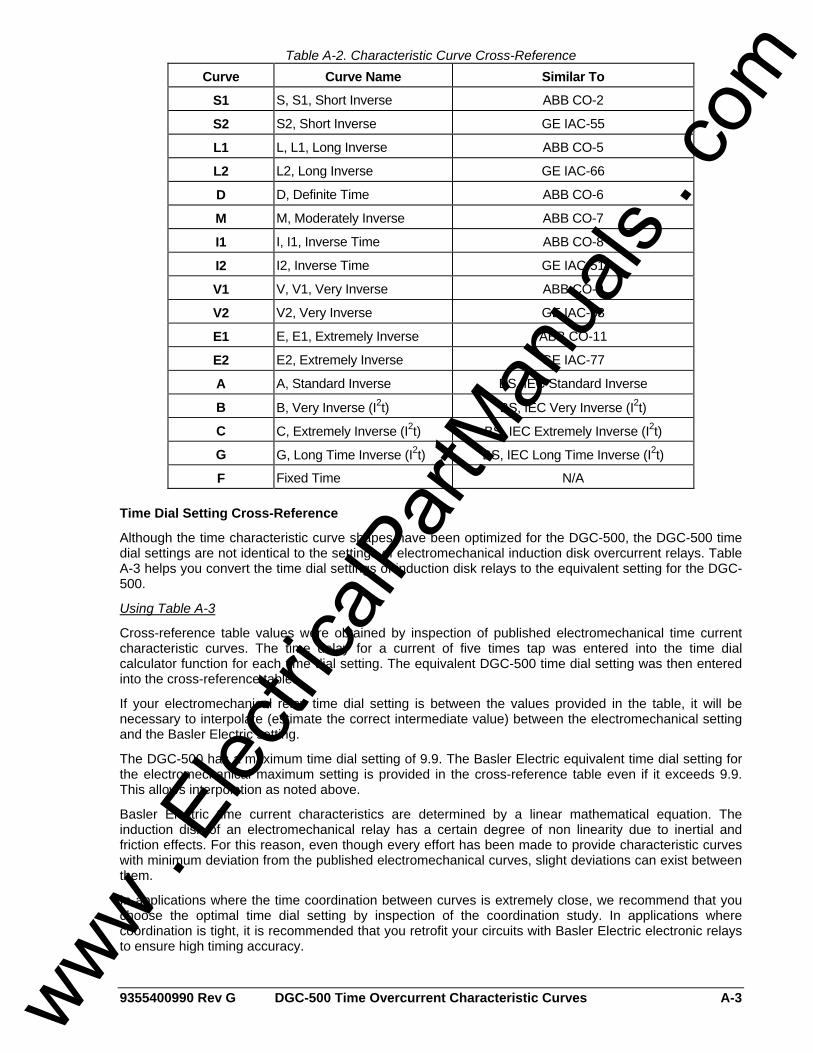
9355400990 Rev G DGC-500 Time Overcurrent Characteristic Curves A-3
Table A-2. Characteristic Curve Cross-Reference Curve Curve Name Similar To
S1 S, S1, Short Inverse ABB CO-2
S2 S2, Short Inverse GE IAC-55
L1 L, L1, Long Inverse ABB CO-5
L2 L2, Long Inverse GE IAC-66
D D, Definite Time ABB CO-6
M M, Moderately Inverse ABB CO-7
I1 I, I1, Inverse Time ABB CO-8
I2 I2, Inverse Time GE IAC-51
V1 V, V1, Very Inverse ABB CO-9
V2 V2, Very Inverse GE IAC-53
E1 E, E1, Extremely Inverse ABB CO-11
E2 E2, Extremely Inverse GE IAC-77
A A, Standard Inverse BS, IEC Standard Inverse
B B, Very Inverse (I2t) BS, IEC Very Inverse (I2t)
C C, Extremely Inverse (I2t) BS, IEC Extremely Inverse (I2t)
G G, Long Time Inverse (I2t) BS, IEC Long Time Inverse (I2t)
F Fixed Time N/A
Time Dial Setting Cross-Reference
Although the time characteristic curve shapes have been optimized for the DGC-500, the DGC-500 time dial settings are not identical to the settings of electromechanical induction disk overcurrent relays. Table A-3 helps you convert the time dial settings of induction disk relays to the equivalent setting for the DGC-500.
Using Table A-3
Cross-reference table values were obtained by inspection of published electromechanical time current characteristic curves. The time delay for a current of five times tap was entered into the time dial calculator function for each time dial setting. The equivalent DGC-500 time dial setting was then entered into the cross-reference table.
If your electromechanical relay time dial setting is between the values provided in the table, it will be necessary to interpolate (estimate the correct intermediate value) between the electromechanical setting and the Basler Electric setting.
The DGC-500 has a maximum time dial setting of 9.9. The Basler Electric equivalent time dial setting for the electromechanical maximum setting is provided in the cross-reference table even if it exceeds 9.9. This allows interpolation as noted above.
Basler Electric time current characteristics are determined by a linear mathematical equation. The induction disk of an electromechanical relay has a certain degree of non linearity due to inertial and friction effects. For this reason, even though every effort has been made to provide characteristic curves with minimum deviation from the published electromechanical curves, slight deviations can exist between them.
In applications where the time coordination between curves is extremely close, we recommend that you choose the optimal time dial setting by inspection of the coordination study. In applications where coordination is tight, it is recommended that you retrofit your circuits with Basler Electric electronic relays to ensure high timing accuracy.
www . El
ectric
alPar
tMan
uals
. com
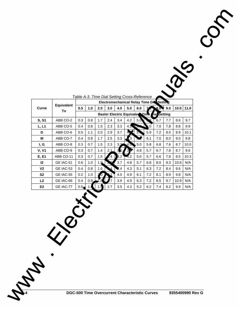
A-4 DGC-500 Time Overcurrent Characteristic Curves 9355400990 Rev G
Table A-3 .Time Dial Setting Cross-Reference Electromechanical Relay Time Dial Setting
0.5 1.0 2.0 3.0 4.0 5.0 6.0 7.0 8.0 9.0 10.0 11.0 Curve Equivalent
To Basler Electric Equivalent Time Dial Setting
S, S1 ABB CO-2 0.3 0.8 1.7 2.4 3.4 4.2 5.0 5.8 6.7 7.7 8.6 9.7
L, L1 ABB CO-5 0.4 0.8 1.5 2.3 3.3 4.2 5.0 6.0 7.0 7.8 8.8 9.9
D ABB CO-6 0.5 1.1 2.0 2.9 3.7 4.5 5.0 5.9 7.2 8.0 8.9 10.1
M ABB CO-7 0.4 0.8 1.7 2.5 3.3 4.3 5.3 6.1 7.0 8.0 9.0 9.8
I, I1 ABB CO-8 0.3 0.7 1.5 2.3 3.2 4.0 5.0 5.8 6.8 7.6 8.7 10.0
V, V1 ABB CO-9 0.3 0.7 1.4 2.1 3.0 3.9 4.8 5.7 6.7 7.8 8.7 9.6
E, E1 ABB CO-11 0.3 0.7 1.5 2.4 3.2 4.2 5.0 5.7 6.6 7.8 8.5 10.3
I2 GE IAC-51 0.6 1.0 1.9 2.7 3.7 4.8 5.7 6.8 8.0 9.3 10.6 N/A
V2 GE IAC-53 0.4 0.8 1.6 2.4 3.4 4.3 5.1 6.3 7.2 8.4 9.6 N/A
S2 GE IAC-55 0.2 1.0 2.0 3.1 4.0 4.9 6.1 7.2 8.1 8.9 9.8 N/A
L2 GE IAC-66 0.4 0.9 1.8 2.7 3.9 4.9 6.3 7.2 8.5 9.7 10.9 N/A
E2 GE IAC-77 0.5 1.0 1.9 2.7 3.5 4.3 5.2 6.2 7.4 8.2 9.9 N/A
www . El
ectric
alPar
tMan
uals
. com
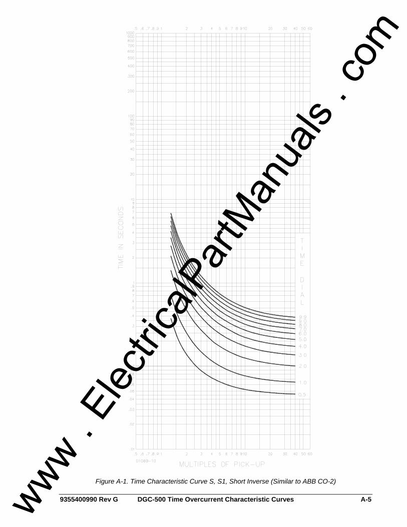
9355400990 Rev G DGC-500 Time Overcurrent Characteristic Curves A-5
Figure A-1. Time Characteristic Curve S, S1, Short Inverse (Similar to ABB CO-2)
www . El
ectric
alPar
tMan
uals
. com
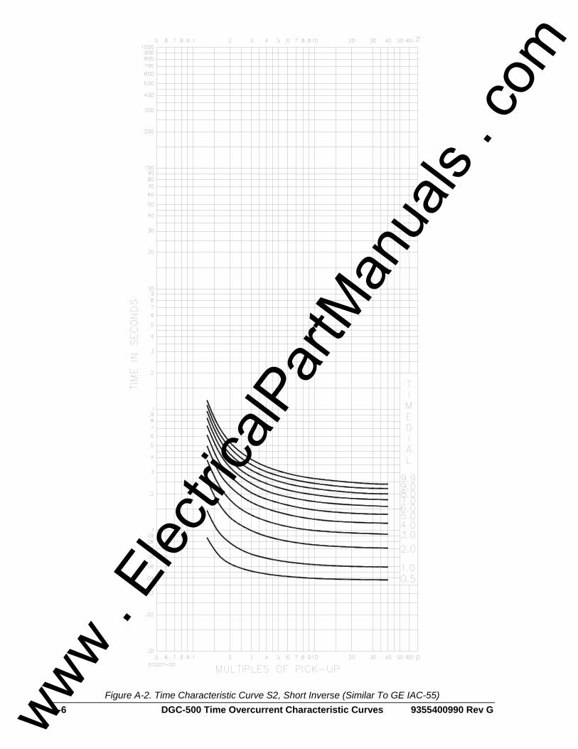
A-6 DGC-500 Time Overcurrent Characteristic Curves 9355400990 Rev G
Figure A-2. Time Characteristic Curve S2, Short Inverse (Similar To GE IAC-55)
www . El
ectric
alPar
tMan
uals
. com
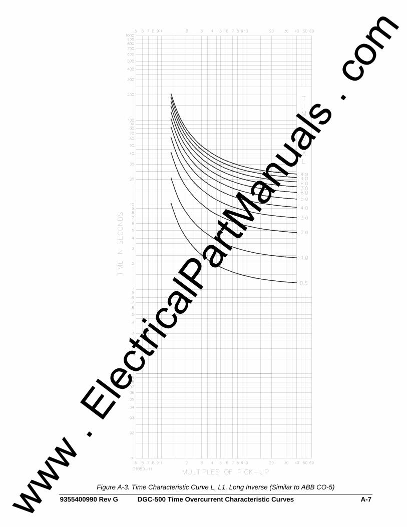
9355400990 Rev G DGC-500 Time Overcurrent Characteristic Curves A-7
Figure A-3. Time Characteristic Curve L, L1, Long Inverse (Similar to ABB CO-5)
www . El
ectric
alPar
tMan
uals
. com
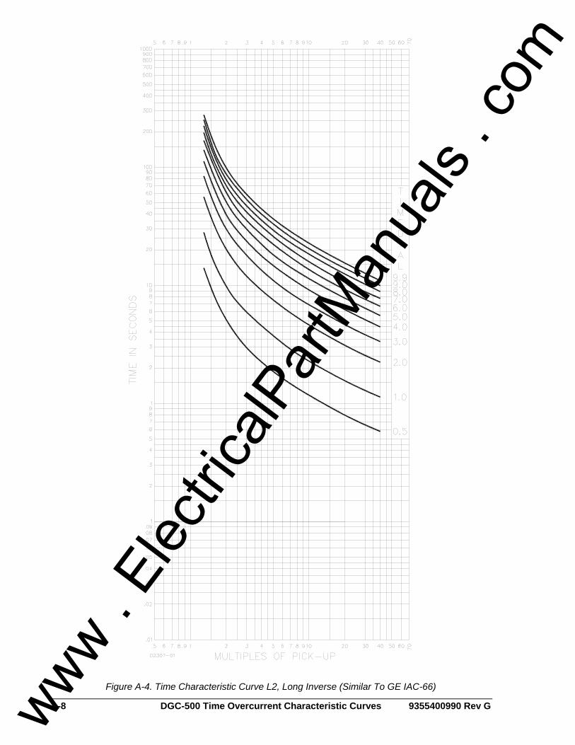
A-8 DGC-500 Time Overcurrent Characteristic Curves 9355400990 Rev G
Figure A-4. Time Characteristic Curve L2, Long Inverse (Similar To GE IAC-66)
www . El
ectric
alPar
tMan
uals
. com
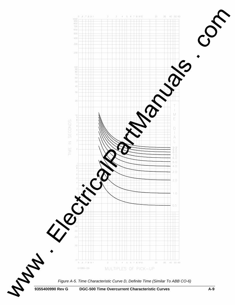
9355400990 Rev G DGC-500 Time Overcurrent Characteristic Curves A-9
Figure A-5. Time Characteristic Curve D, Definite Time (Similar To ABB CO-6)
www . El
ectric
alPar
tMan
uals
. com
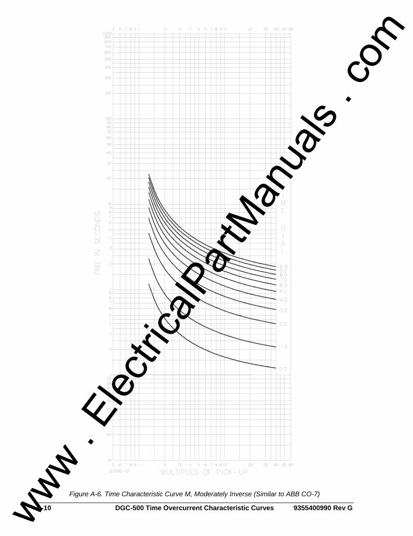
A-10 DGC-500 Time Overcurrent Characteristic Curves 9355400990 Rev G
Figure A-6. Time Characteristic Curve M, Moderately Inverse (Similar to ABB CO-7)
www . El
ectric
alPar
tMan
uals
. com
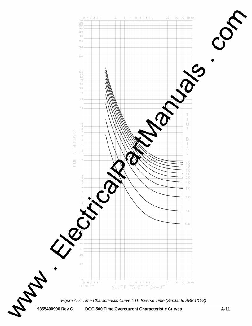
9355400990 Rev G DGC-500 Time Overcurrent Characteristic Curves A-11
Figure A-7. Time Characteristic Curve I, I1, Inverse Time (Similar to ABB CO-8)
www . El
ectric
alPar
tMan
uals
. com
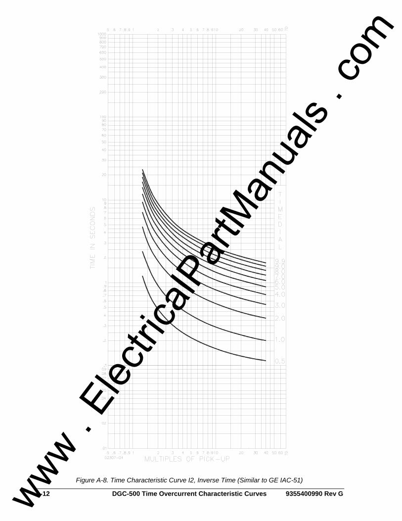
A-12 DGC-500 Time Overcurrent Characteristic Curves 9355400990 Rev G
Figure A-8. Time Characteristic Curve I2, Inverse Time (Similar to GE IAC-51)
www . El
ectric
alPar
tMan
uals
. com
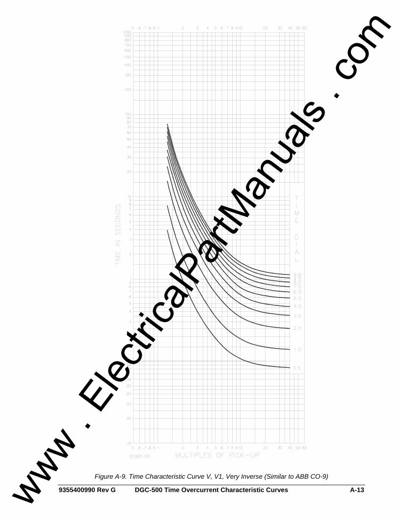
9355400990 Rev G DGC-500 Time Overcurrent Characteristic Curves A-13
Figure A-9. Time Characteristic Curve V, V1, Very Inverse (Similar to ABB CO-9)
www . El
ectric
alPar
tMan
uals
. com
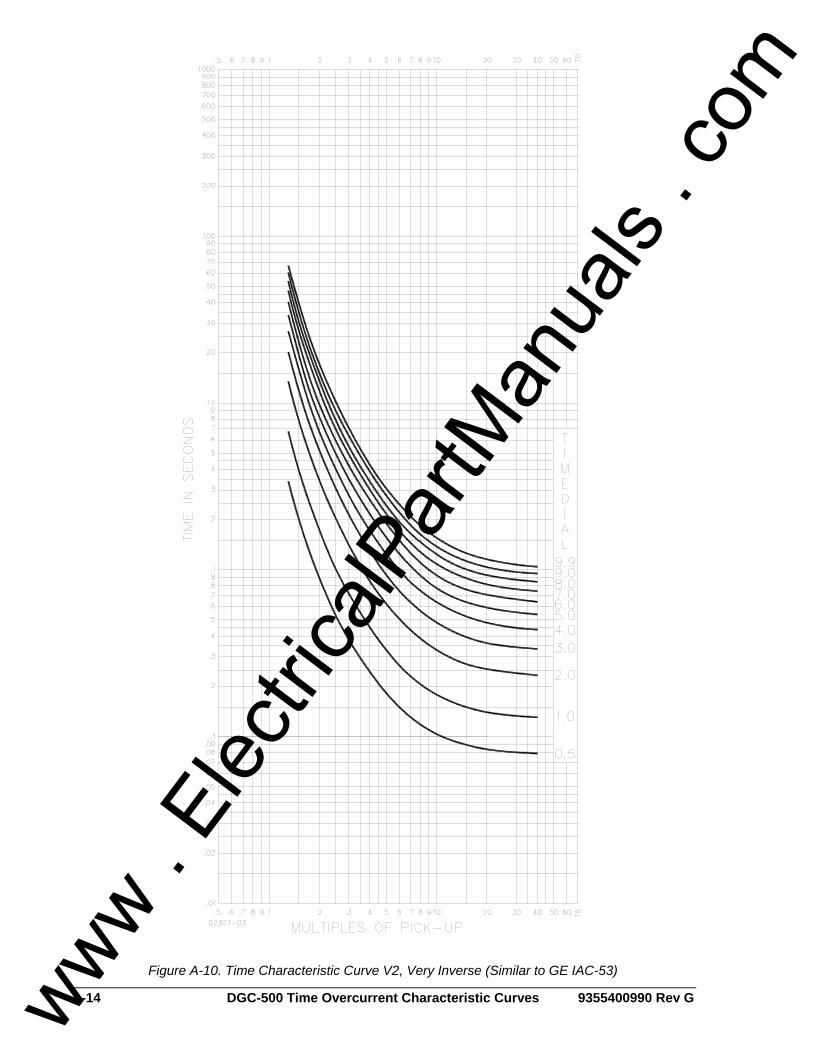
A-14 DGC-500 Time Overcurrent Characteristic Curves 9355400990 Rev G
Figure A-10. Time Characteristic Curve V2, Very Inverse (Similar to GE IAC-53)
www . El
ectric
alPar
tMan
uals
. com
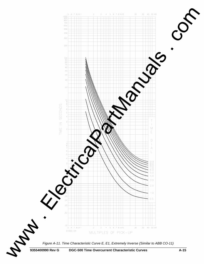
9355400990 Rev G DGC-500 Time Overcurrent Characteristic Curves A-15
Figure A-11. Time Characteristic Curve E, E1, Extremely Inverse (Similar to ABB CO-11)
www . El
ectric
alPar
tMan
uals
. com
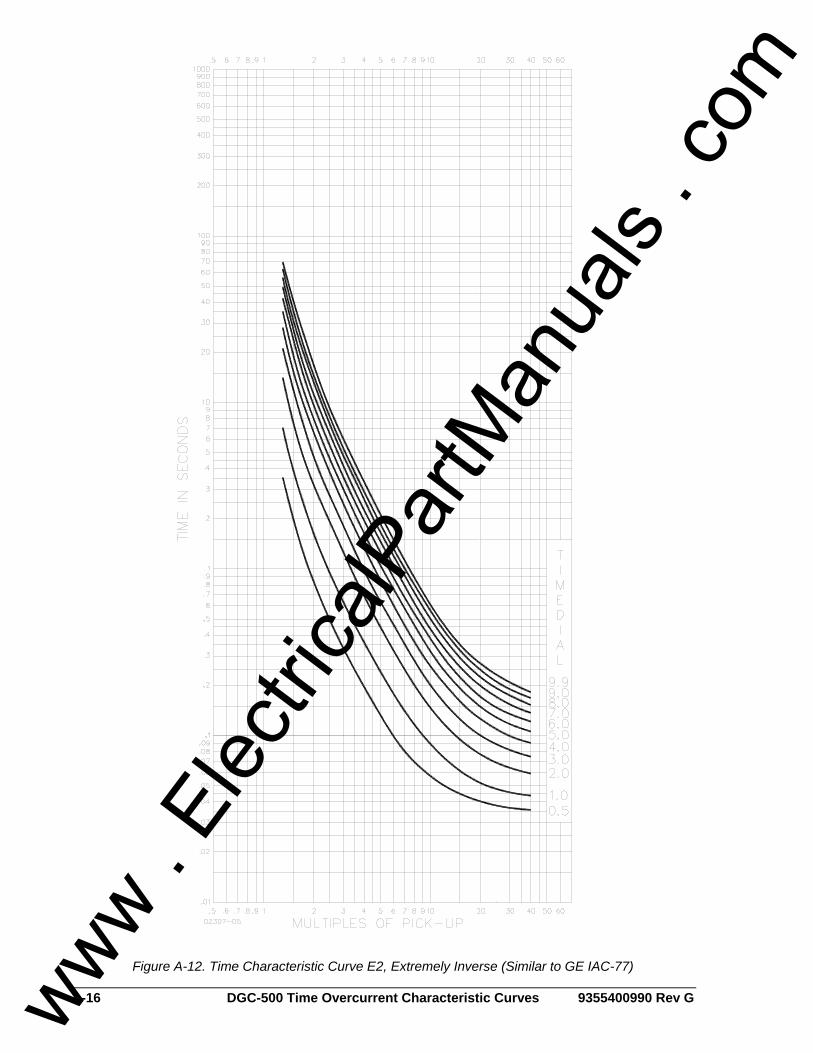
A-16 DGC-500 Time Overcurrent Characteristic Curves 9355400990 Rev G
Figure A-12. Time Characteristic Curve E2, Extremely Inverse (Similar to GE IAC-77)
www . El
ectric
alPar
tMan
uals
. com
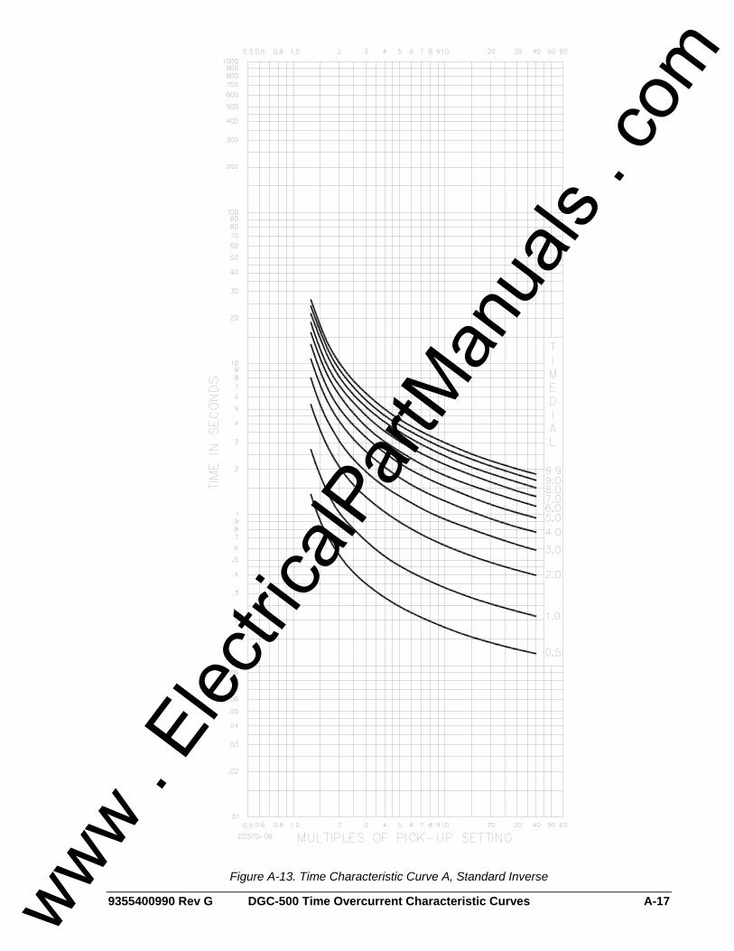
9355400990 Rev G DGC-500 Time Overcurrent Characteristic Curves A-17
Figure A-13. Time Characteristic Curve A, Standard Inverse
www . El
ectric
alPar
tMan
uals
. com
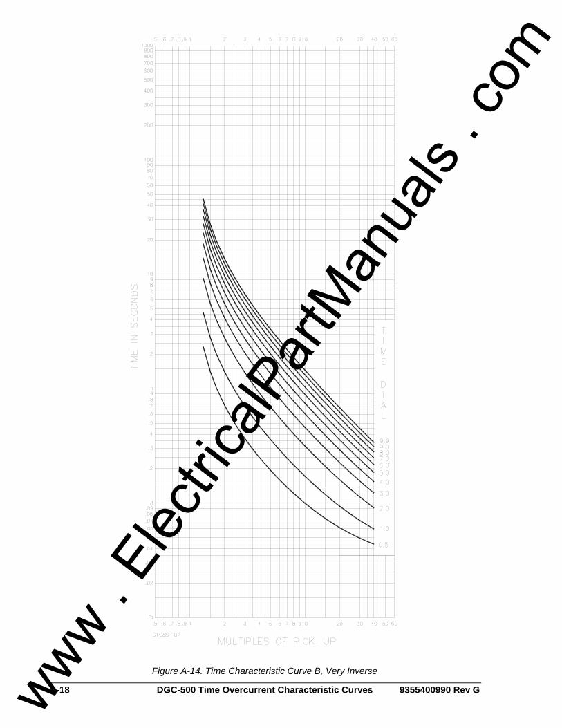
A-18 DGC-500 Time Overcurrent Characteristic Curves 9355400990 Rev G
Figure A-14. Time Characteristic Curve B, Very Inverse
www . El
ectric
alPar
tMan
uals
. com
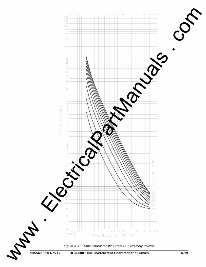
9355400990 Rev G DGC-500 Time Overcurrent Characteristic Curves A-19
Figure A-15. Time Characteristic Curve C, Extremely Inverse
www . El
ectric
alPar
tMan
uals
. com
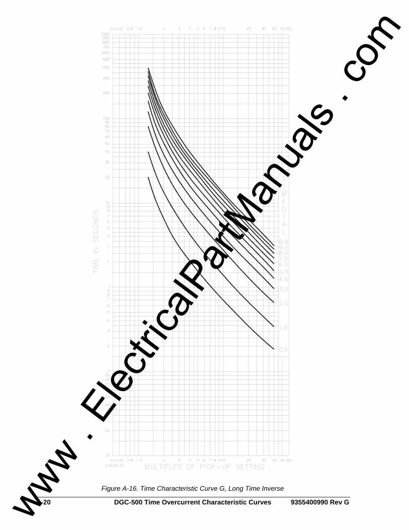
A-20 DGC-500 Time Overcurrent Characteristic Curves 9355400990 Rev G
Figure A-16. Time Characteristic Curve G, Long Time Inverse
www . El
ectric
alPar
tMan
uals
. com
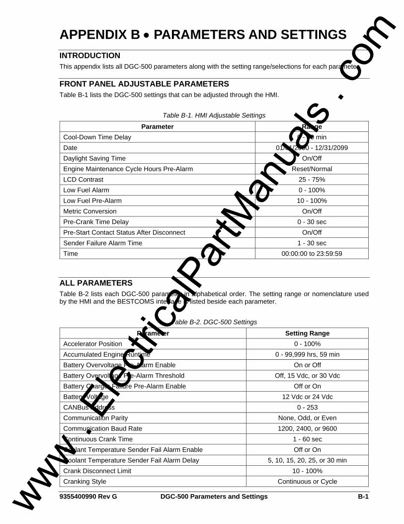
9355400990 Rev G DGC-500 Parameters and Settings B-1
APPENDIX B • PARAMETERS AND SETTINGS INTRODUCTION This appendix lists all DGC-500 parameters along with the setting range/selections for each parameter.
FRONT PANEL ADJUSTABLE PARAMETERS Table B-1 lists the DGC-500 settings that can be adjusted through the HMI.
Table B-1. HMI Adjustable Settings
Parameter Range Cool-Down Time Delay 0 - 60 min Date 01/01/2000 - 12/31/2099 Daylight Saving Time On/Off Engine Maintenance Cycle Hours Pre-Alarm Reset/Normal LCD Contrast 25 - 75% Low Fuel Alarm 0 - 100% Low Fuel Pre-Alarm 10 - 100% Metric Conversion On/Off Pre-Crank Time Delay 0 - 30 sec Pre-Start Contact Status After Disconnect On/Off Sender Failure Alarm Time 1 - 30 sec Time 00:00:00 to 23:59:59
ALL PARAMETERS Table B-2 lists each DGC-500 parameter in alphabetical order. The setting range or nomenclature used by the HMI and the BESTCOMS interface is listed beside each parameter.
Table B-2. DGC-500 Settings
Parameter Setting Range Accelerator Position 0 - 100% Accumulated Engine Runtime 0 - 99,999 hrs, 59 min Battery Overvoltage Pre-Alarm Enable On or Off Battery Overvoltage Pre-Alarm Threshold Off, 15 Vdc, or 30 Vdc Battery Charger Failure Pre-Alarm Enable Off or On Battery Voltage 12 Vdc or 24 Vdc CANBus Address 0 - 253 Communication Parity None, Odd, or Even Communication Baud Rate 1200, 2400, or 9600 Continuous Crank Time 1 - 60 sec Coolant Temperature Sender Fail Alarm Enable Off or On Coolant Temperature Sender Fail Alarm Delay 5, 10, 15, 20, 25, or 30 min Crank Disconnect Limit 10 - 100% Cranking Style Continuous or Cycle
www . El
ectric
alPar
tMan
uals
. com
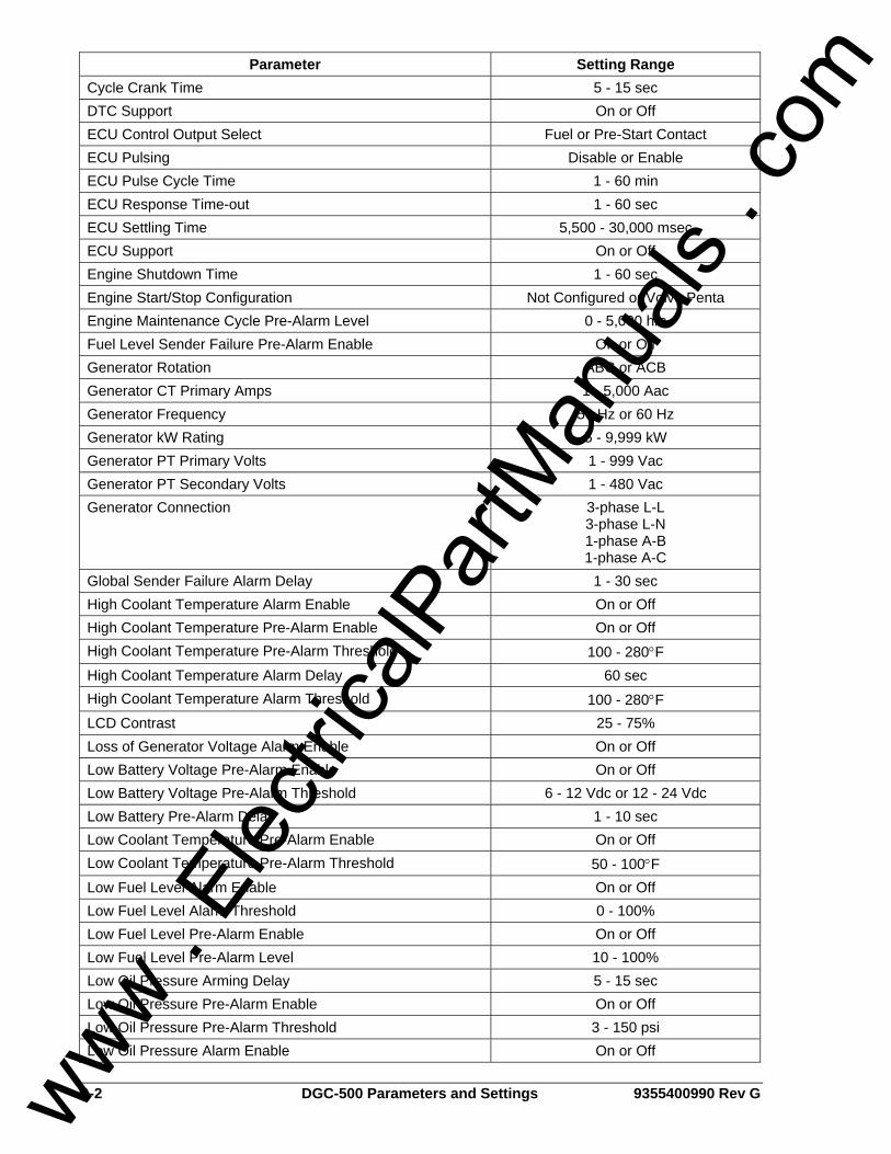
B-2 DGC-500 Parameters and Settings 9355400990 Rev G
Parameter Setting Range Cycle Crank Time 5 - 15 sec DTC Support On or Off ECU Control Output Select Fuel or Pre-Start Contact ECU Pulsing Disable or Enable ECU Pulse Cycle Time 1 - 60 min ECU Response Time-out 1 - 60 sec ECU Settling Time 5,500 - 30,000 msec ECU Support On or Off Engine Shutdown Time 1 - 60 sec Engine Start/Stop Configuration Not Configured or Volvo Penta Engine Maintenance Cycle Pre-Alarm Level 0 - 5,000 hrs Fuel Level Sender Failure Pre-Alarm Enable On or Off Generator Rotation ABC or ACB Generator CT Primary Amps 1 - 5,000 Aac Generator Frequency 50 Hz or 60 Hz Generator kW Rating 5 - 9,999 kW Generator PT Primary Volts 1 - 999 Vac Generator PT Secondary Volts 1 - 480 Vac Generator Connection 3-phase L-L
3-phase L-N 1-phase A-B 1-phase A-C
Global Sender Failure Alarm Delay 1 - 30 sec High Coolant Temperature Alarm Enable On or Off High Coolant Temperature Pre-Alarm Enable On or Off High Coolant Temperature Pre-Alarm Threshold 100 - 280°F High Coolant Temperature Alarm Delay 60 sec High Coolant Temperature Alarm Threshold 100 - 280°F LCD Contrast 25 - 75% Loss of Generator Voltage Alarm Enable On or Off Low Battery Voltage Pre-Alarm Enable On or Off Low Battery Voltage Pre-Alarm Threshold 6 - 12 Vdc or 12 - 24 Vdc Low Battery Pre-Alarm Delay 1 - 10 sec Low Coolant Temperature Pre-Alarm Enable On or Off Low Coolant Temperature Pre-Alarm Threshold 50 - 100°F Low Fuel Level Alarm Enable On or Off Low Fuel Level Alarm Threshold 0 - 100% Low Fuel Level Pre-Alarm Enable On or Off Low Fuel Level Pre-Alarm Level 10 - 100% Low Oil Pressure Arming Delay 5 - 15 sec Low Oil Pressure Pre-Alarm Enable On or Off Low Oil Pressure Pre-Alarm Threshold 3 - 150 psi Low Oil Pressure Alarm Enable On or Off
www . El
ectric
alPar
tMan
uals
. com
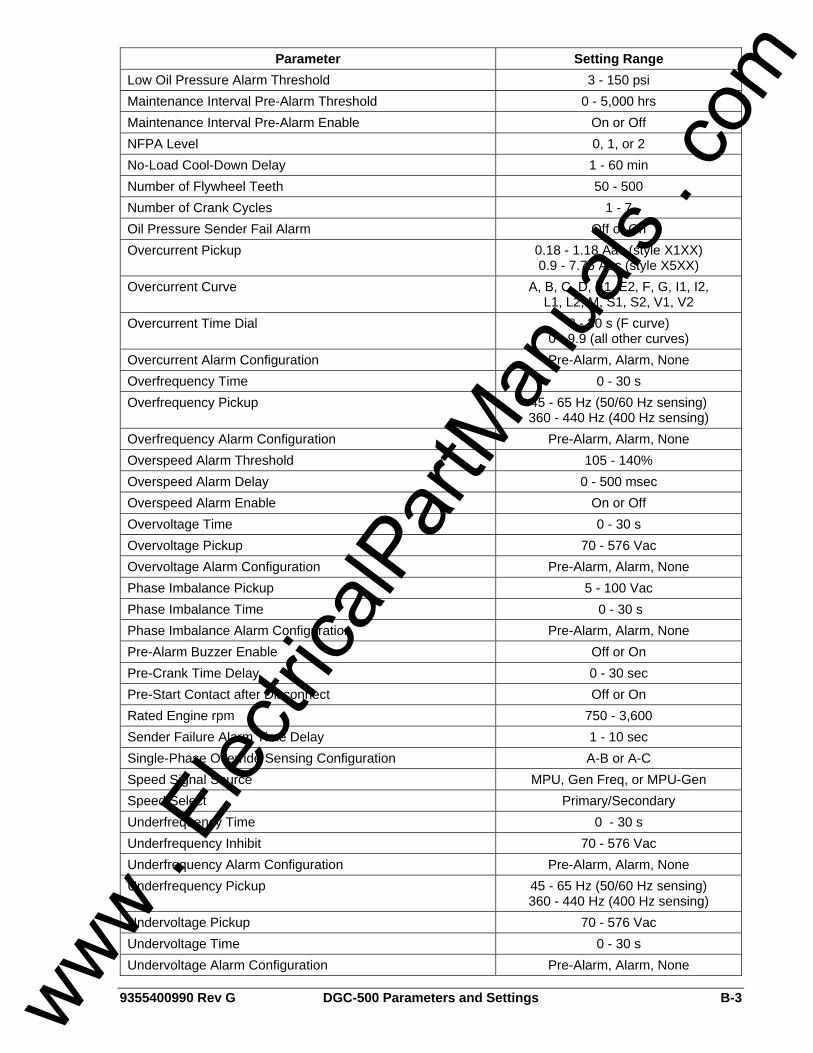
9355400990 Rev G DGC-500 Parameters and Settings B-3
Parameter Setting Range Low Oil Pressure Alarm Threshold 3 - 150 psi Maintenance Interval Pre-Alarm Threshold 0 - 5,000 hrs Maintenance Interval Pre-Alarm Enable On or Off NFPA Level 0, 1, or 2 No-Load Cool-Down Delay 1 - 60 min Number of Flywheel Teeth 50 - 500 Number of Crank Cycles 1 - 7 Oil Pressure Sender Fail Alarm Off or On Overcurrent Pickup 0.18 - 1.18 Aac (style X1XX)
0.9 - 7.75 Aac (style X5XX) Overcurrent Curve A, B, C, D, E1, E2, F, G, I1, I2,
L1, L2, M, S1, S2, V1, V2 Overcurrent Time Dial 0 - 30 s (F curve)
0 - 9.9 (all other curves) Overcurrent Alarm Configuration Pre-Alarm, Alarm, None Overfrequency Time 0 - 30 s Overfrequency Pickup 45 - 65 Hz (50/60 Hz sensing)
360 - 440 Hz (400 Hz sensing) Overfrequency Alarm Configuration Pre-Alarm, Alarm, None Overspeed Alarm Threshold 105 - 140% Overspeed Alarm Delay 0 - 500 msec Overspeed Alarm Enable On or Off Overvoltage Time 0 - 30 s Overvoltage Pickup 70 - 576 Vac Overvoltage Alarm Configuration Pre-Alarm, Alarm, None Phase Imbalance Pickup 5 - 100 Vac Phase Imbalance Time 0 - 30 s Phase Imbalance Alarm Configuration Pre-Alarm, Alarm, None Pre-Alarm Buzzer Enable Off or On Pre-Crank Time Delay 0 - 30 sec Pre-Start Contact after Disconnect Off or On Rated Engine rpm 750 - 3,600 Sender Failure Alarm Time Delay 1 - 10 sec Single-Phase Override Sensing Configuration A-B or A-C Speed Signal Source MPU, Gen Freq, or MPU-Gen Speed Select Primary/Secondary Underfrequency Time 0 - 30 s Underfrequency Inhibit 70 - 576 Vac Underfrequency Alarm Configuration Pre-Alarm, Alarm, None Underfrequency Pickup 45 - 65 Hz (50/60 Hz sensing)
360 - 440 Hz (400 Hz sensing) Undervoltage Pickup 70 - 576 Vac Undervoltage Time 0 - 30 s Undervoltage Alarm Configuration Pre-Alarm, Alarm, None
www . El
ectric
alPar
tMan
uals
. com
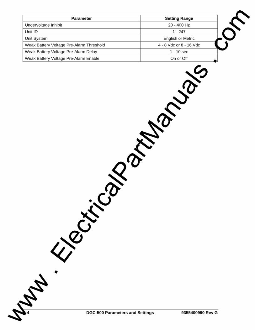
B-4 DGC-500 Parameters and Settings 9355400990 Rev G
Parameter Setting Range Undervoltage Inhibit 20 - 400 Hz Unit ID 1 - 247 Unit System English or Metric Weak Battery Voltage Pre-Alarm Threshold 4 - 8 Vdc or 8 - 16 Vdc Weak Battery Voltage Pre-Alarm Delay 1 - 10 sec Weak Battery Voltage Pre-Alarm Enable On or Off
www . El
ectric
alPar
tMan
uals
. com
9355400990 Rev G DGC-500 Settings Record C-1
APPENDIX C • SETTINGS RECORD INTRODUCTION This appendix provides a complete list of DGC-500 settings. This list is provided in the form of a settings record that you can use to record information relative to your application. DGC-500 settings are organized in the following groups. • Sensing Transformers • System • Cranking • Pre-Alarms • Alarms • Generator Protection • Serial Communication • J1939 Interface • Miscellaneous
www . El
ectric
alPar
tMan
uals
. com
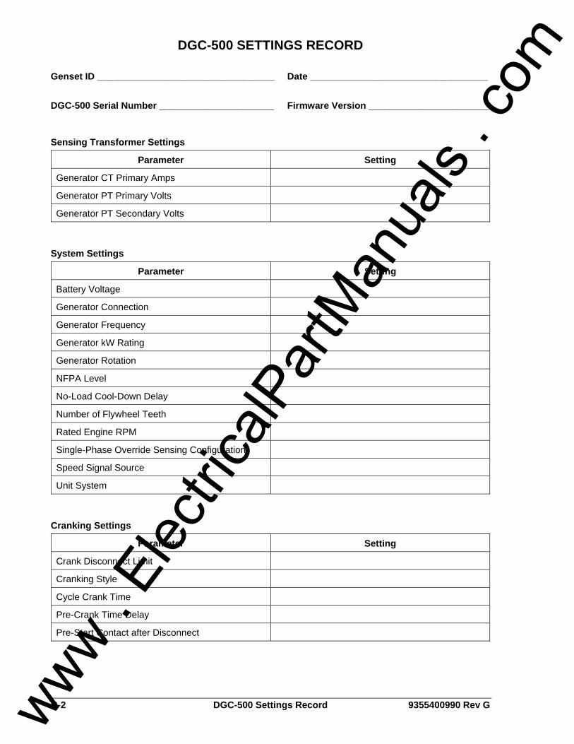
C-2 DGC-500 Settings Record 9355400990 Rev G
DGC-500 SETTINGS RECORD Genset ID __________________________________ Date __________________________________ DGC-500 Serial Number ______________________ Firmware Version _______________________
Sensing Transformer Settings
Parameter Setting
Generator CT Primary Amps
Generator PT Primary Volts
Generator PT Secondary Volts
System Settings
Parameter Setting
Battery Voltage
Generator Connection
Generator Frequency
Generator kW Rating
Generator Rotation
NFPA Level
No-Load Cool-Down Delay
Number of Flywheel Teeth
Rated Engine RPM
Single-Phase Override Sensing Configuration
Speed Signal Source
Unit System
Cranking Settings
Parameter Setting
Crank Disconnect Limit
Cranking Style
Cycle Crank Time
Pre-Crank Time Delay
Pre-Start Contact after Disconnect
www . El
ectric
alPar
tMan
uals
. com
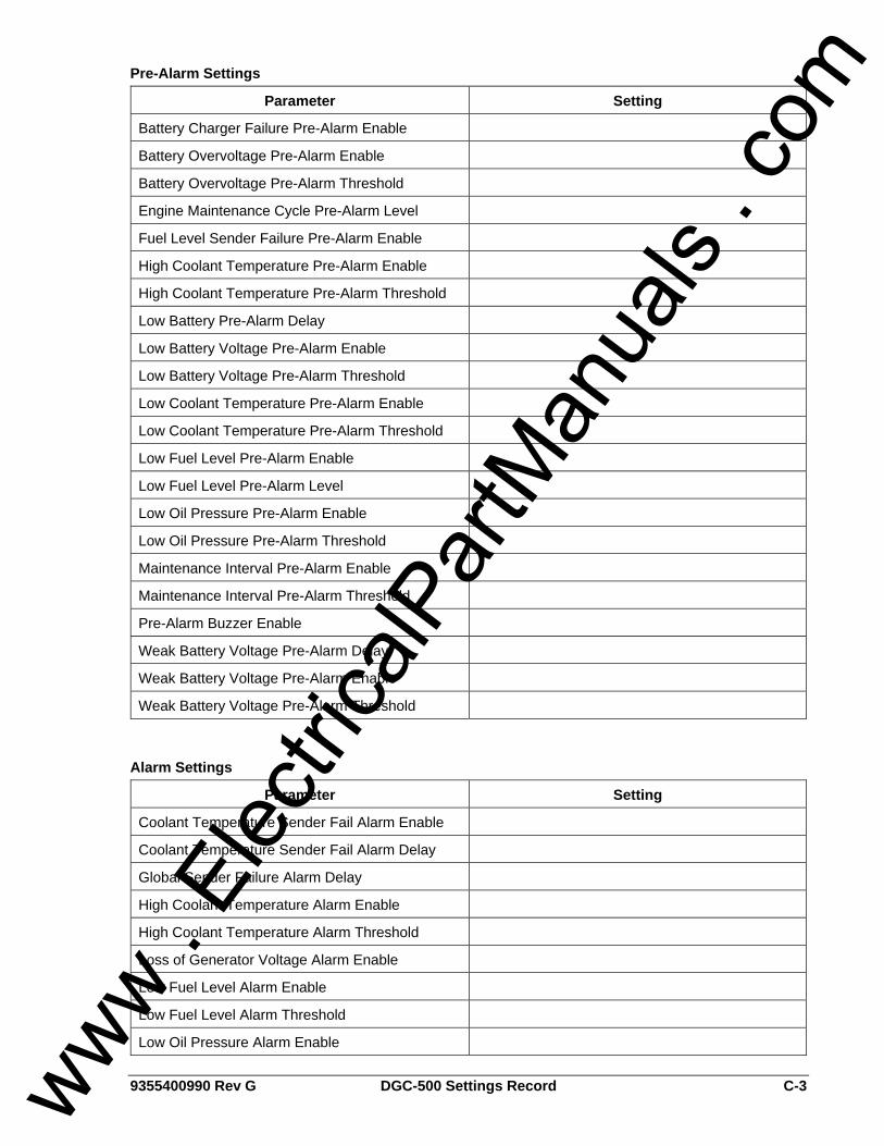
9355400990 Rev G DGC-500 Settings Record C-3
Pre-Alarm Settings
Parameter Setting
Battery Charger Failure Pre-Alarm Enable
Battery Overvoltage Pre-Alarm Enable
Battery Overvoltage Pre-Alarm Threshold
Engine Maintenance Cycle Pre-Alarm Level
Fuel Level Sender Failure Pre-Alarm Enable
High Coolant Temperature Pre-Alarm Enable
High Coolant Temperature Pre-Alarm Threshold
Low Battery Pre-Alarm Delay
Low Battery Voltage Pre-Alarm Enable
Low Battery Voltage Pre-Alarm Threshold
Low Coolant Temperature Pre-Alarm Enable
Low Coolant Temperature Pre-Alarm Threshold
Low Fuel Level Pre-Alarm Enable
Low Fuel Level Pre-Alarm Level
Low Oil Pressure Pre-Alarm Enable
Low Oil Pressure Pre-Alarm Threshold
Maintenance Interval Pre-Alarm Enable
Maintenance Interval Pre-Alarm Threshold
Pre-Alarm Buzzer Enable
Weak Battery Voltage Pre-Alarm Delay
Weak Battery Voltage Pre-Alarm Enable
Weak Battery Voltage Pre-Alarm Threshold
Alarm Settings
Parameter Setting
Coolant Temperature Sender Fail Alarm Enable
Coolant Temperature Sender Fail Alarm Delay
Global Sender Failure Alarm Delay
High Coolant Temperature Alarm Enable
High Coolant Temperature Alarm Threshold
Loss of Generator Voltage Alarm Enable
Low Fuel Level Alarm Enable
Low Fuel Level Alarm Threshold
Low Oil Pressure Alarm Enable
www . El
ectric
alPar
tMan
uals
. com
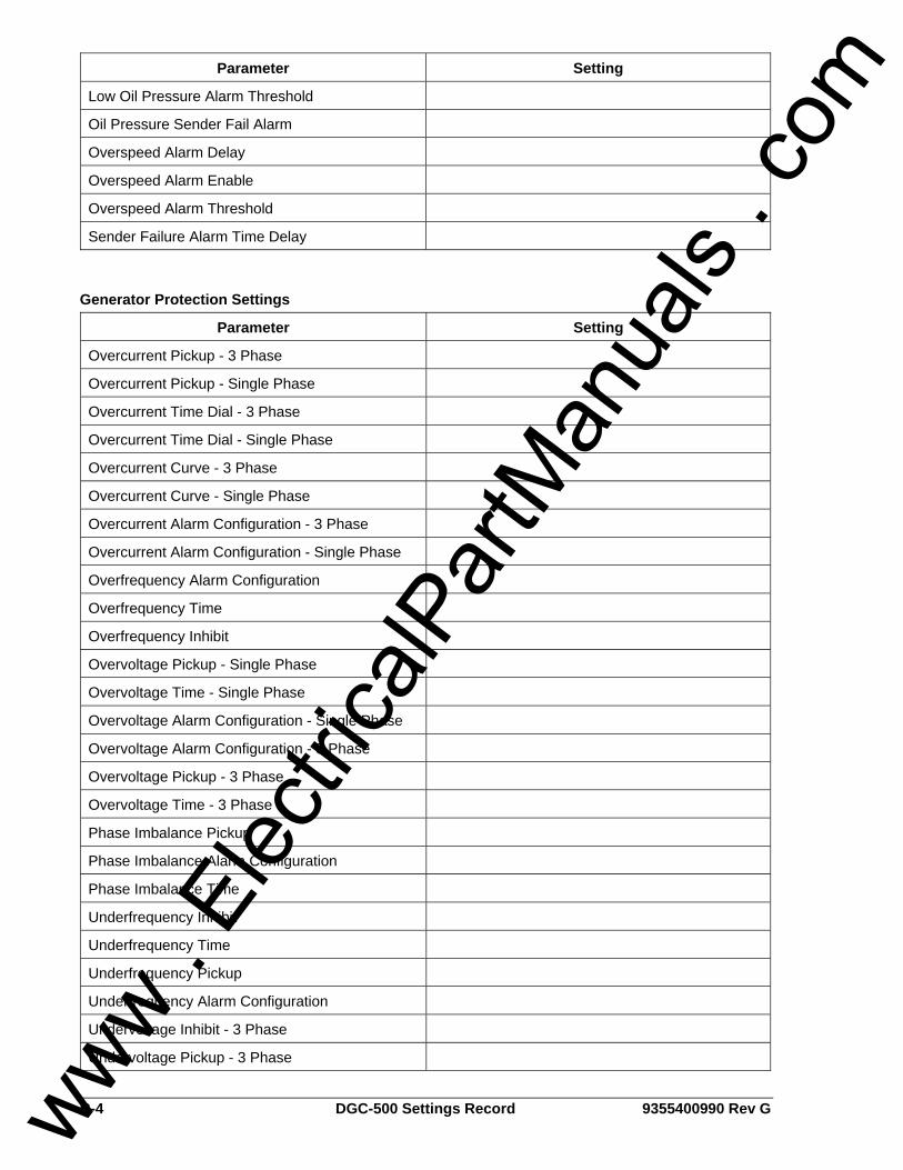
C-4 DGC-500 Settings Record 9355400990 Rev G
Parameter Setting
Low Oil Pressure Alarm Threshold
Oil Pressure Sender Fail Alarm
Overspeed Alarm Delay
Overspeed Alarm Enable
Overspeed Alarm Threshold
Sender Failure Alarm Time Delay
Generator Protection Settings
Parameter Setting
Overcurrent Pickup - 3 Phase
Overcurrent Pickup - Single Phase
Overcurrent Time Dial - 3 Phase
Overcurrent Time Dial - Single Phase
Overcurrent Curve - 3 Phase
Overcurrent Curve - Single Phase
Overcurrent Alarm Configuration - 3 Phase
Overcurrent Alarm Configuration - Single Phase
Overfrequency Alarm Configuration
Overfrequency Time
Overfrequency Inhibit
Overvoltage Pickup - Single Phase
Overvoltage Time - Single Phase
Overvoltage Alarm Configuration - Single Phase
Overvoltage Alarm Configuration - 3 Phase
Overvoltage Pickup - 3 Phase
Overvoltage Time - 3 Phase
Phase Imbalance Pickup
Phase Imbalance Alarm Configuration
Phase Imbalance Time
Underfrequency Inhibit
Underfrequency Time
Underfrequency Pickup
Underfrequency Alarm Configuration
Undervoltage Inhibit - 3 Phase
Undervoltage Pickup - 3 Phase
www . El
ectric
alPar
tMan
uals
. com
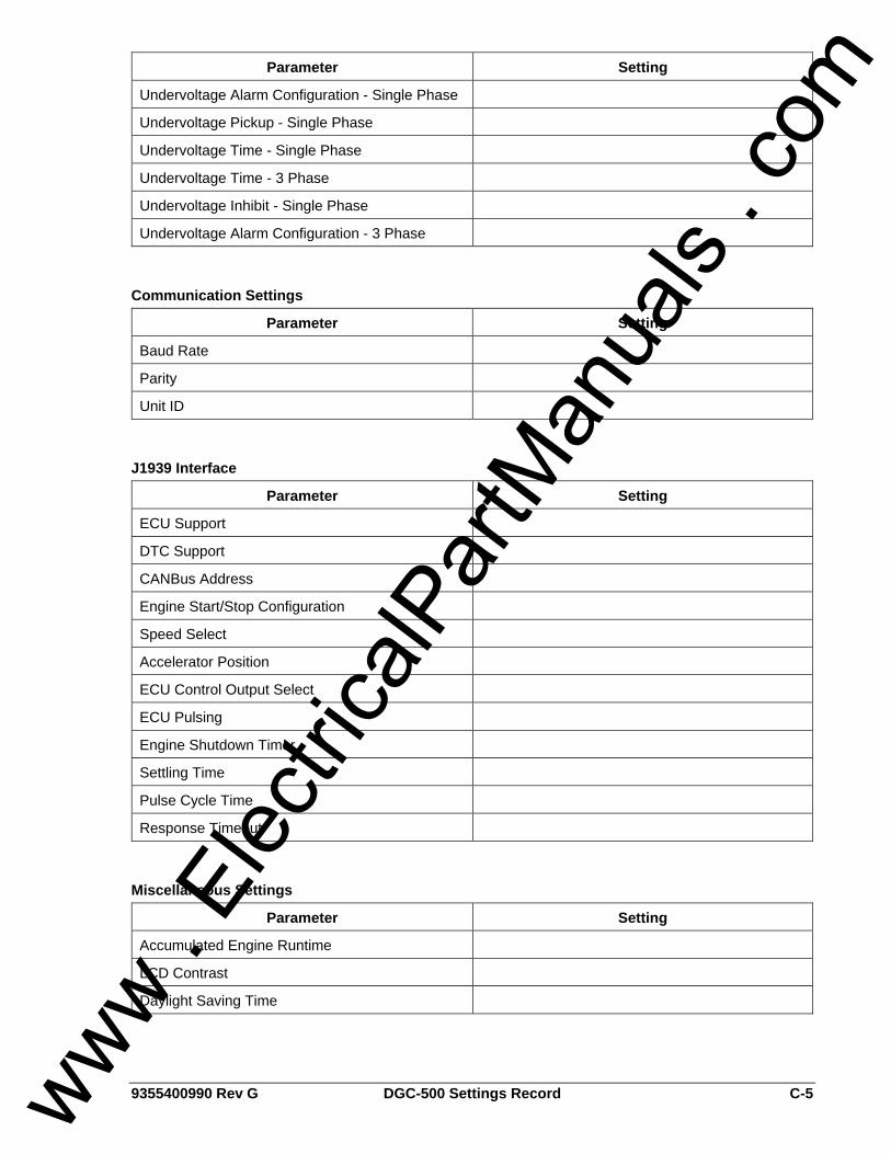
9355400990 Rev G DGC-500 Settings Record C-5
Parameter Setting
Undervoltage Alarm Configuration - Single Phase
Undervoltage Pickup - Single Phase
Undervoltage Time - Single Phase
Undervoltage Time - 3 Phase
Undervoltage Inhibit - Single Phase
Undervoltage Alarm Configuration - 3 Phase
Communication Settings
Parameter Setting
Baud Rate
Parity
Unit ID
J1939 Interface
Parameter Setting
ECU Support
DTC Support
CANBus Address
Engine Start/Stop Configuration
Speed Select
Accelerator Position
ECU Control Output Select
ECU Pulsing
Engine Shutdown Timer
Settling Time
Pulse Cycle Time
Response Timeout
Miscellaneous Settings
Parameter Setting
Accumulated Engine Runtime
LCD Contrast
Daylight Saving Time
www . El
ectric
alPar
tMan
uals
. com

C-6 DGC-500 Settings Record 9355400990 Rev G
This page intentionally left blank.
www . El
ectric
alPar
tMan
uals
. com
ROUTE 143, BOX 269 HIGHLAND, IL 62249 USA
http://www.basler.com, [email protected] PHONE +1 618-654-2341 FAX +1 618-654-2351 www .
Elec
tricalP
artM
anua
ls . c
om