digital communication systems material... · slope overload distortion in delta modulation slope...
TRANSCRIPT
Jamadagni H S DC/V1/2004 1
Digital Communication Systems
H. S. Jamadagni, CEDT, IISc, Bangalore
Topics in Digital Communications
Digital communication system advantages and disadvantagesDigital communication system
classificationDigitization of analog signalsDigital transmission systemsData communication systemsIntegrated Services Digital Network
and other advanced digital communication systems
Jamadagni H S DC/V1/2004 2
Digital Communication advantages
Reliable communication; less sensitivity to changes in environmental conditions (temperature, etc.)Easy multiplexingEasy signaling
Hook status, address digits, call progress informationVoice and data integrationEasy processing like encryption and compressionEasy system performance monitoring
QOS monitoringIntegration of transmission and switchingSignal regeneration, operation at low SNR, superior performanceIntegration of services leading to ISDN
Jamadagni H S DC/V1/2004 3
Increased bandwidth64 KB for a 4 KHz channel, without compression (However, less with compression)
Need for precision timingBit, character, frame synchronization needed
Analogue to Digital and Digital to Analogue conversionsVery often non-linear ADC and DAC used, some performance degradation
Higher complexity
Digital Communication System Disadvantages
Jamadagni H S DC/V1/2004 4
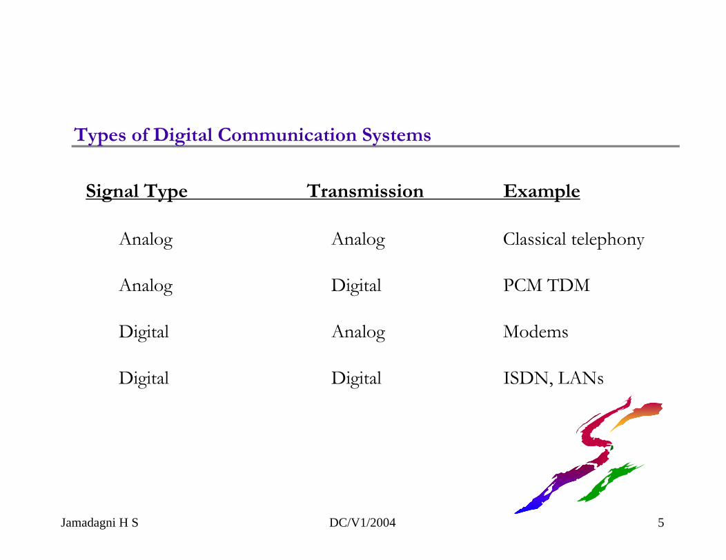
Types of Digital Communication Systems
Signal Type Transmission Example
Analog Analog Classical telephony
Analog Digital PCM TDM
Digital Analog Modems
Digital Digital ISDN, LANs
Jamadagni H S DC/V1/2004 5
Time
Am
plitu
de
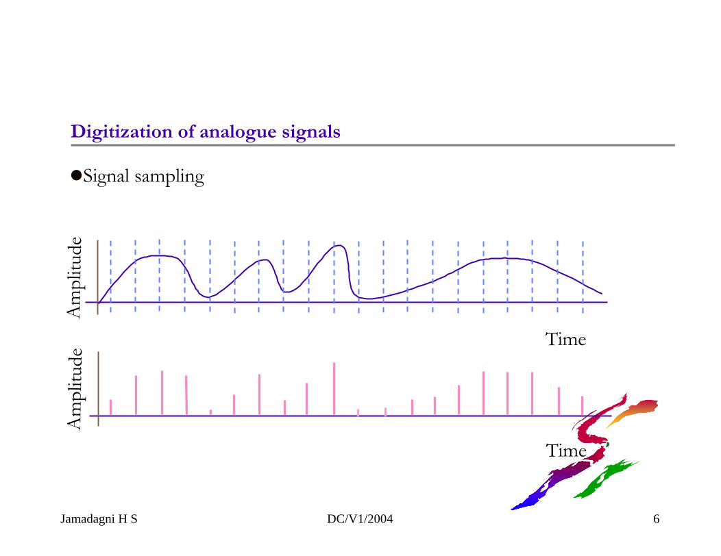
Digitization of analogue signals
Time
Am
plitu
de
Signal sampling
Jamadagni H S DC/V1/2004 6
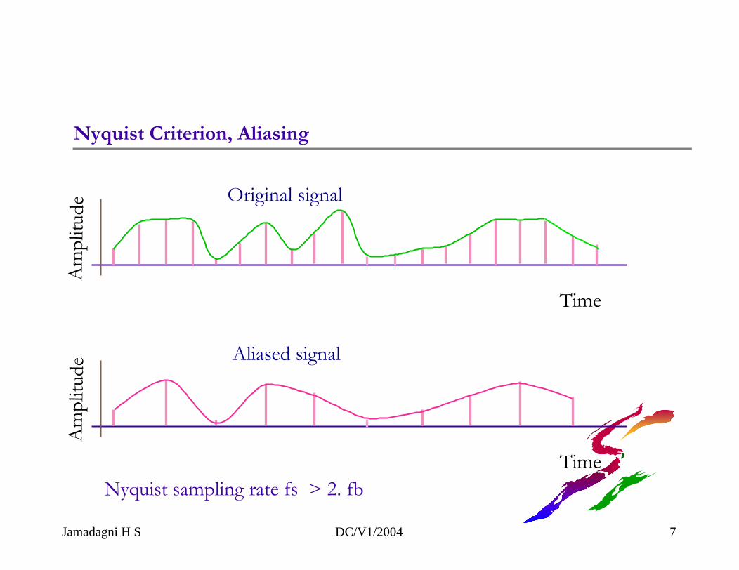
Nyquist Criterion, Aliasing
Time
Am
plitu
de
Time
Am
plitu
de
Original signal
Aliased signal
Nyquist sampling rate fs > 2. fb
Jamadagni H S DC/V1/2004 7
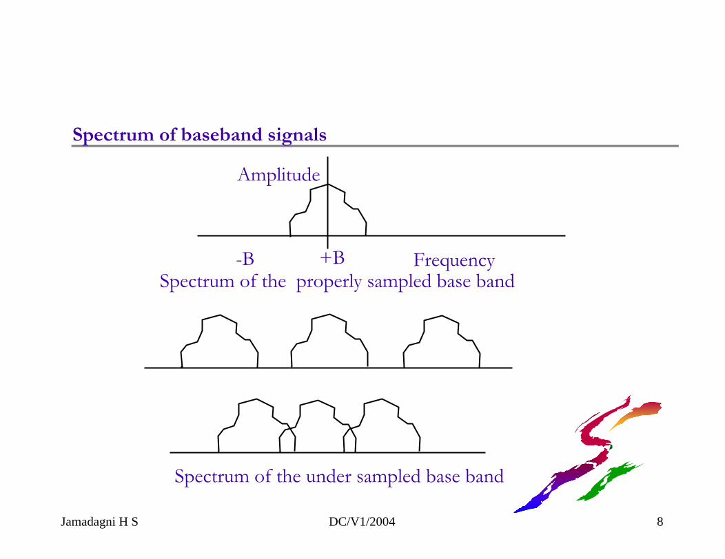
Amplitude
-B +B FrequencySpectrum of the properly sampled base band
Spectrum of the under sampled base band
Spectrum of baseband signals
Jamadagni H S DC/V1/2004 8
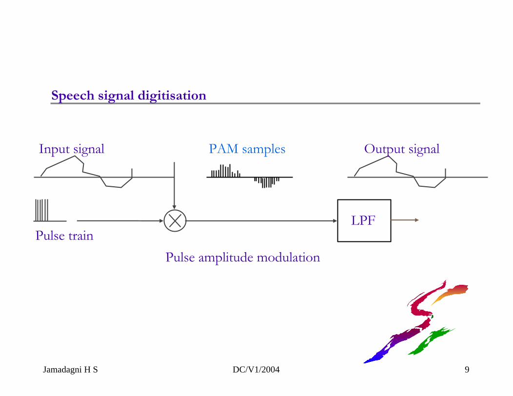
Speech signal digitisation
LPF
Input signal
Pulse train
Output signal
Pulse amplitude modulation
PAM samples
Jamadagni H S DC/V1/2004 9
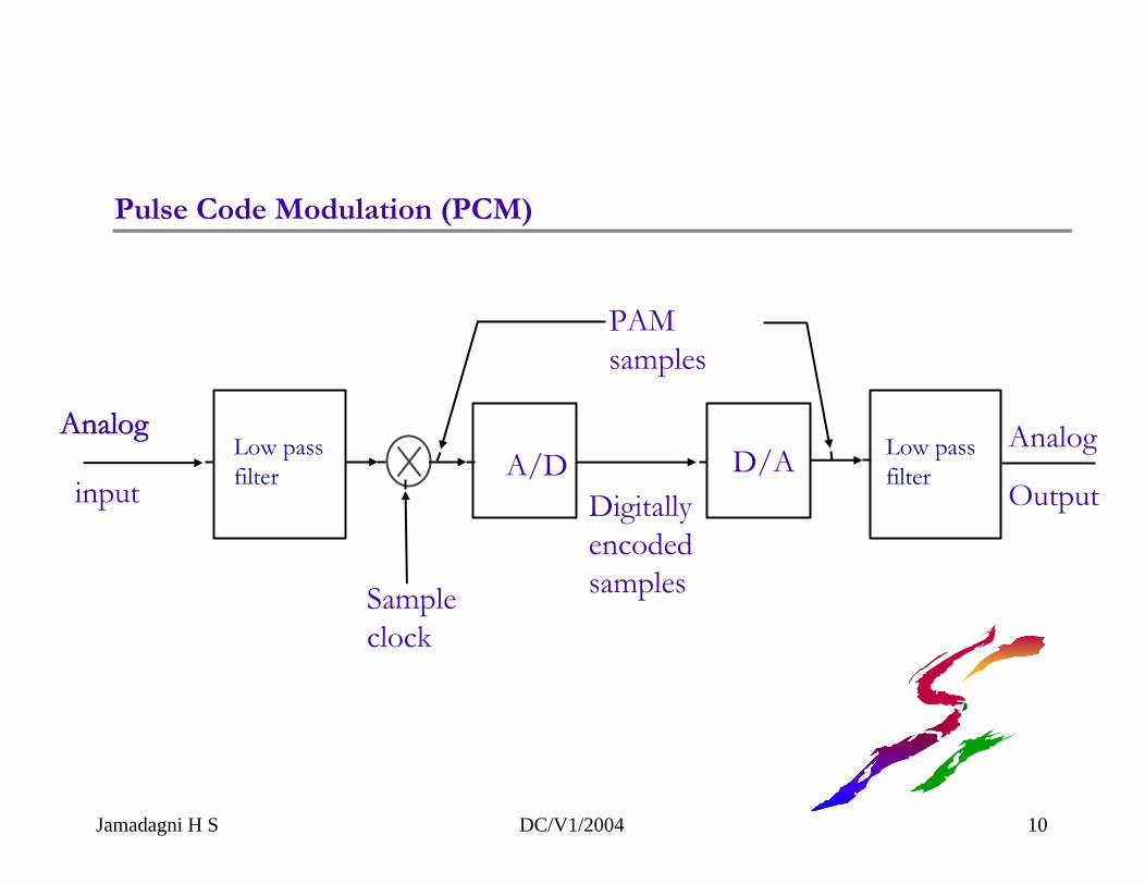
Analog
inputA/D
Digitallyencodedsamples
D/AAnalog
Output
AnalogAnalog
PAM samples
Sampleclock
Pulse Code Modulation (PCM)
Low passfilter
Low passfilter
Jamadagni H S DC/V1/2004 10
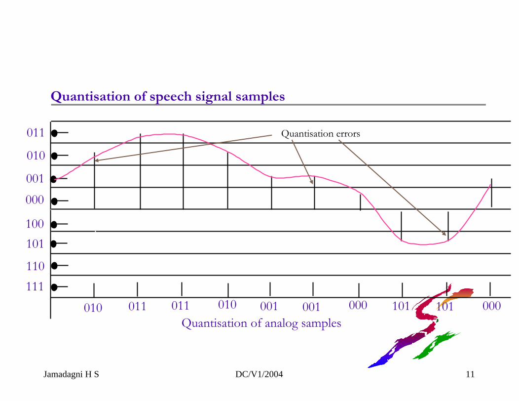
010 011 011 010 001 001 000 101 101 000Quantisation of analog samples
Quantisation of speech signal samples
Quantisation errors011
010
001000
100101
110111
Jamadagni H S DC/V1/2004 11
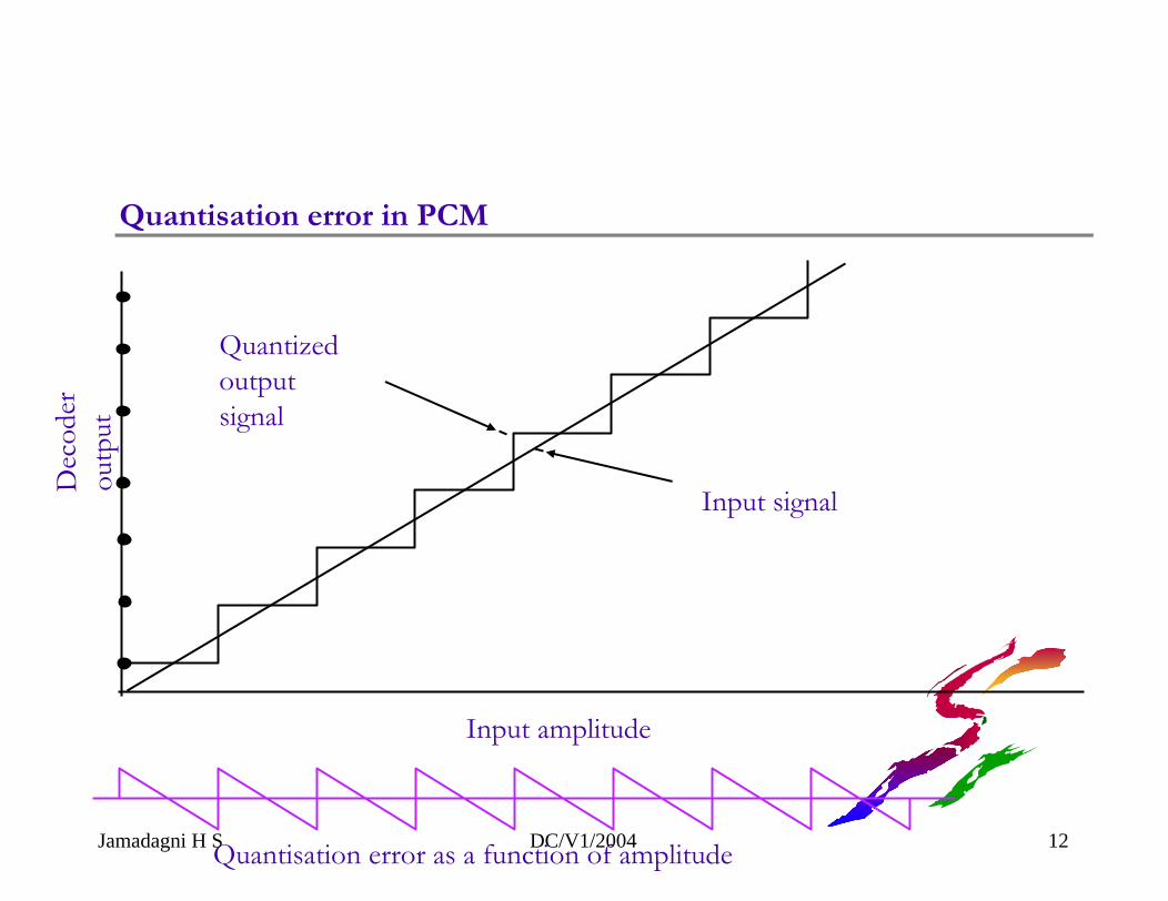
Quantisation error in PCM
Quantized outputsignal
Input signal
ou
Input amplitude
Jamadagni H S DC/V1/2004 12
Dec
oder
tp
ut
Quantisation error as a function of amplitude
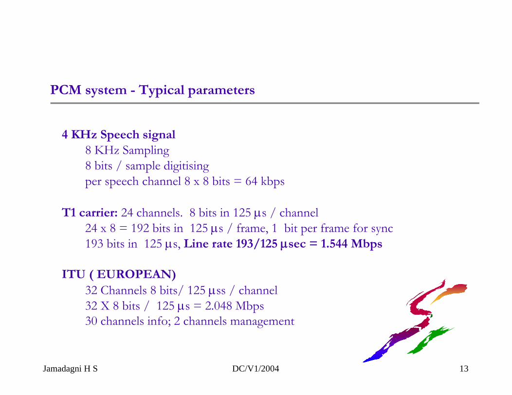
PCM system - Typical parameters
4 KHz Speech signal8 KHz Sampling8 bits / sample digitisingper speech channel 8 x 8 bits = 64 kbps
T1 carrier: 24 channels. 8 bits in 125 µs / channel24 x 8 = 192 bits in 125 µs / frame, 1 bit per frame for sync193 bits in 125 µs, Line rate 193/125 µsec = 1.544 Mbps
ITU ( EUROPEAN)32 Channels 8 bits/ 125 µss / channel32 X 8 bits / 125 µs = 2.048 Mbps30 channels info; 2 channels management
Jamadagni H S DC/V1/2004 13
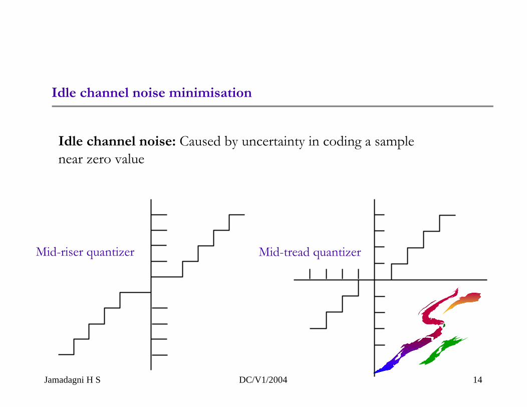
Idle channel noise minimisation
Jamadagni H S DC/V1/2004 14
Mid-riser quantizer Mid-tread quantizer
Idle channel noise: Caused by uncertainty in coding a sample near zero value
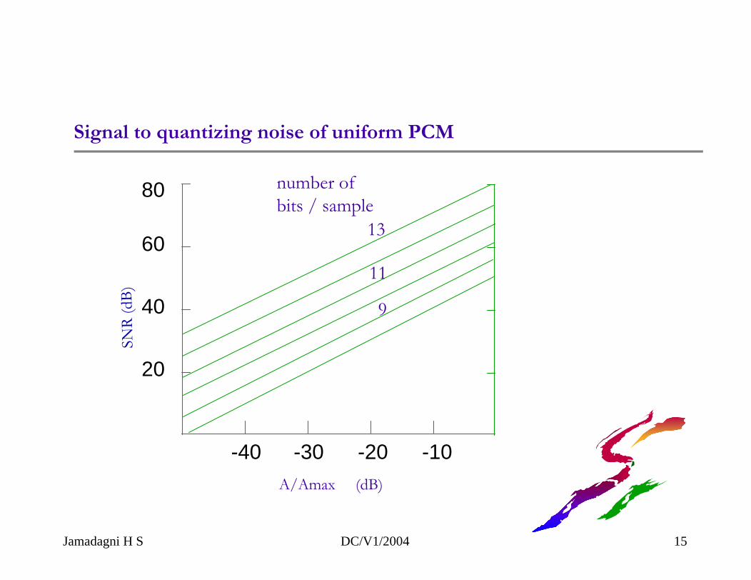
Signal to quantizing noise of uniform PCM
number of bits / sample
13
11
9
A/Amax (dB)
SNR
(dB)
80
-10-20-30-40
20
40
60
Jamadagni H S DC/V1/2004 15
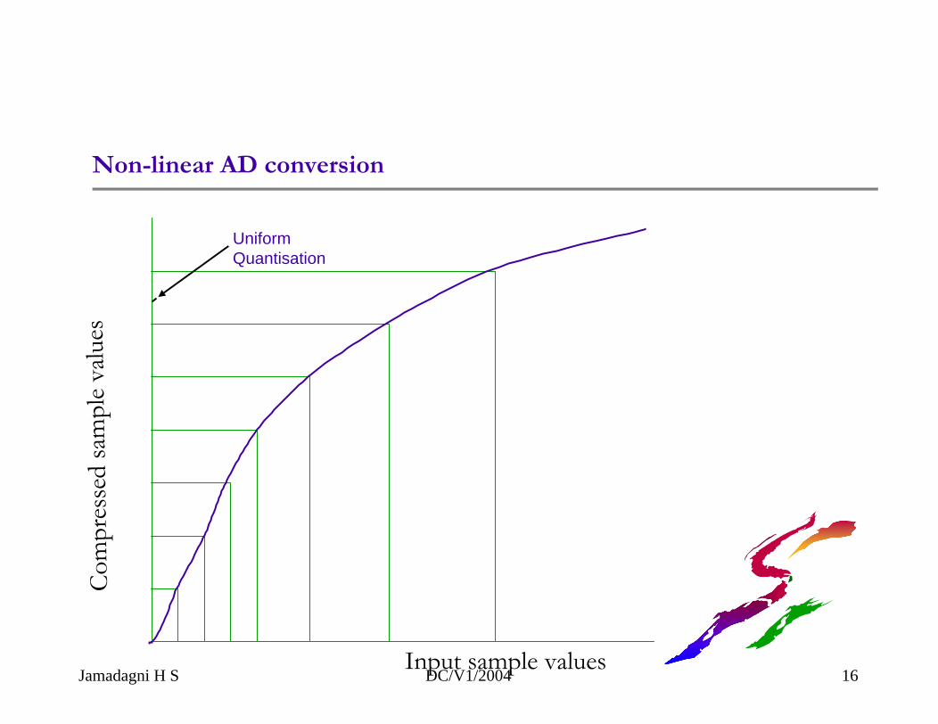
Non-linear AD conversion
Jamadagni H S DC/V1/2004 16
Uniform Quantisation
Input sample values
Com
pres
sed
sam
ple
valu
es
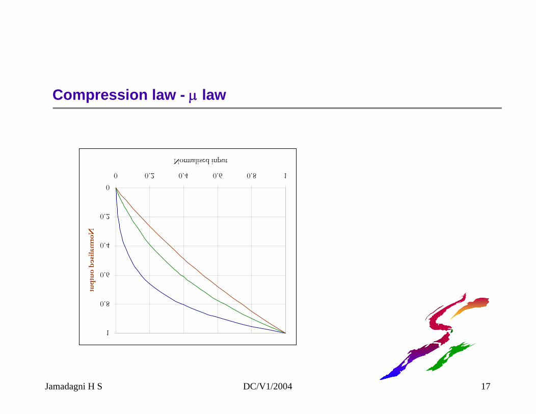
Compression law - µ law
00.2
0.40.6
0.81
0 0.2 0.4 0.6 0.8 1
Normalised input
Norm
alised ou
tpu
t
Jamadagni H S DC/V1/2004 17
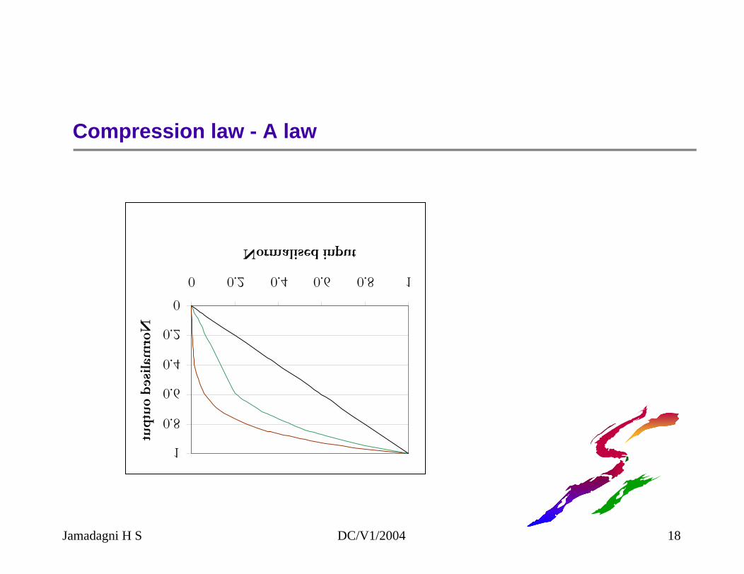
Compression law - A law
00.2
0.40.6
0.81
0 0.2 0.4 0.6 0.8 1
Normalised input
Norm
alised ou
tpu
t
Jamadagni H S DC/V1/2004 18
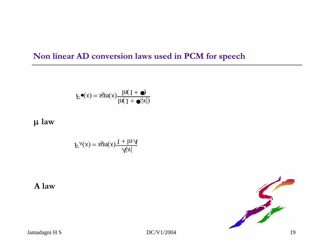
Non linear AD conversion laws used in PCM for speech
F (x) = sgn(x)ln(1 + .|x|)
ln(1 + )
FA(x) = sgn(x)A|x|
1 + lnA
µ law
A law
Jamadagni H S DC/V1/2004 19
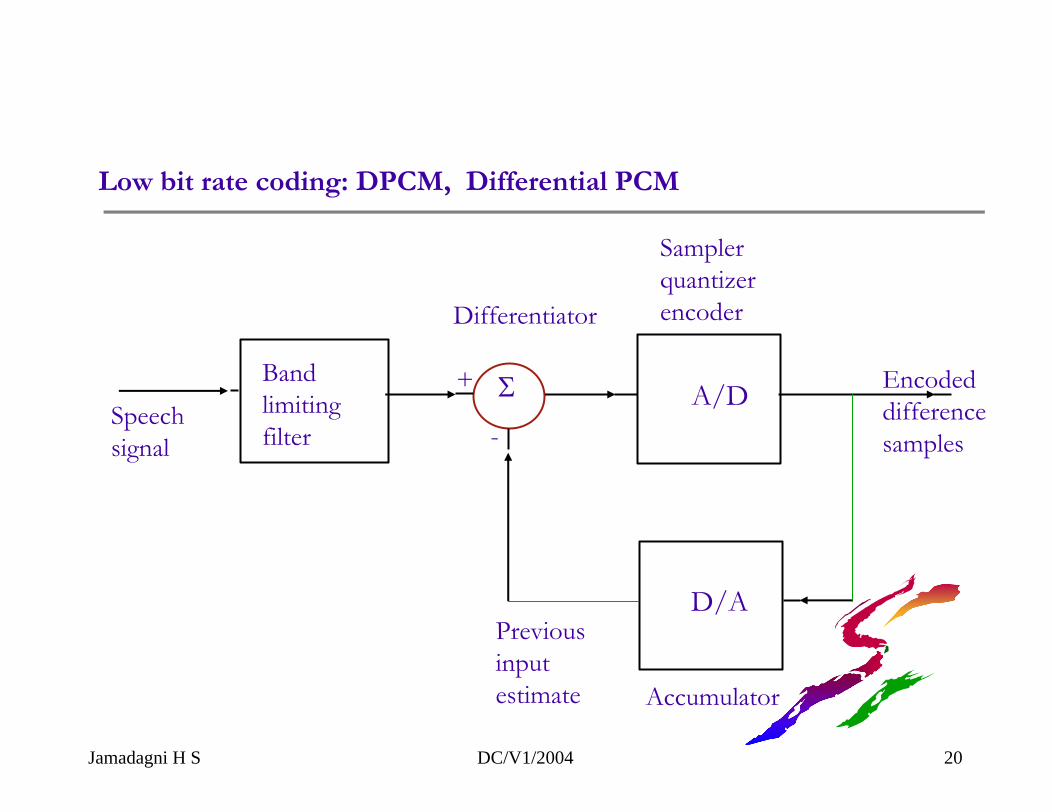
Low bit rate coding: DPCM, Differential PCM
A/D
D/A
+
-
ΣSpeech signal
Band limitingfilter
Differentiator
Samplerquantizerencoder
Previousinputestimate Accumulator
Encodeddifferencesamples
Jamadagni H S DC/V1/2004 20
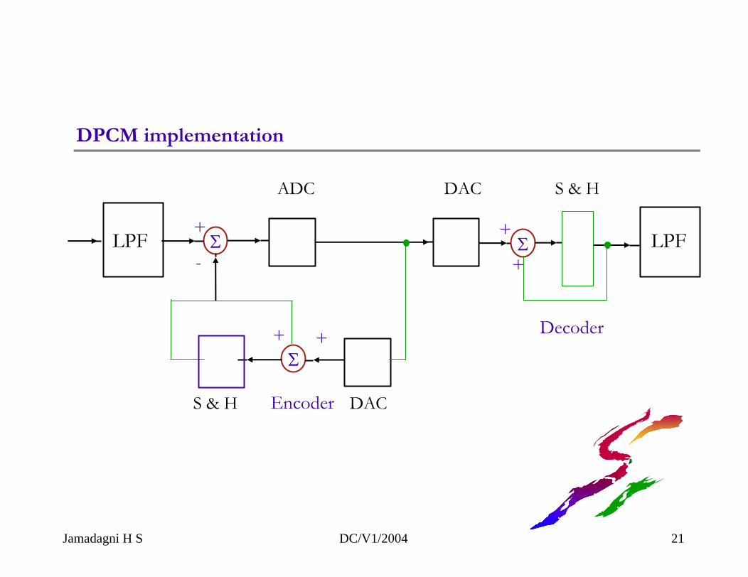
Σ
Σ
+
-
+ +
Σ+
+
Encoder
Decoder
ADC DAC S & H
S & H DAC
DPCM implementation
LPF LPF
Jamadagni H S DC/V1/2004 21
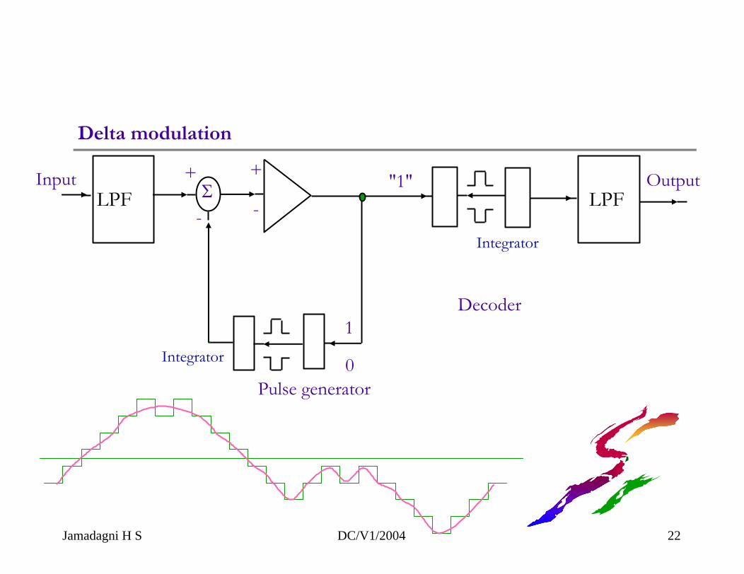
Delta modulation
Jamadagni H S DC/V1/2004 22
Σ+
-
Pulse generator
-
+
1
0
"1"Input Output
Decoder
Integrator
Integrator
LPF LPF
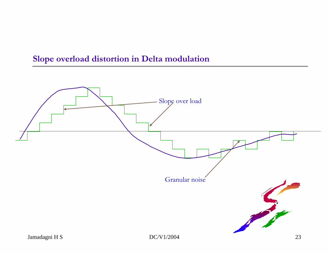
Slope overload distortion in Delta modulation
Slope over load
Granular noise
Jamadagni H S DC/V1/2004 23
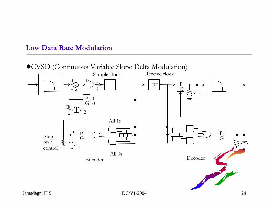
Low Data Rate Modulation
CVSD (Continuous Variable Slope Delta Modulation)
S-+ +
-10
C2
PG
10
C1
PGStep
sizecontrol
All 1s
All 0sEncoder
FF
Sample clock
PG
PG
Decoder
Receive clock
Jamadagni H S DC/V1/2004 24
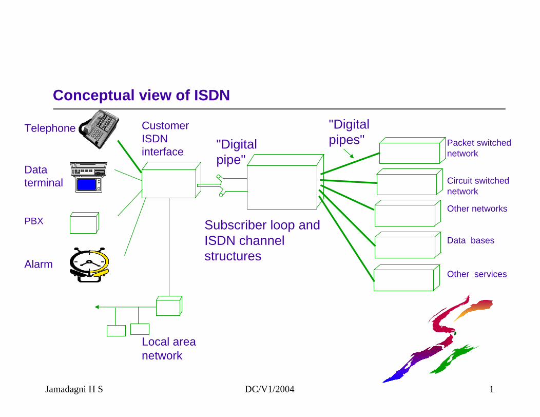
Conceptual view of ISDN
Jamadagni H S DC/V1/2004 1
PBX
Local area network
Packet switched network
Circuit switched network
Other networks
Data bases
Other services
Telephone
Data terminal
Alarm
CustomerISDNinterface "Digital
pipe"
"Digital pipes"
Subscriber loop andISDN channel structures
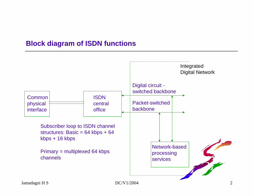
Block diagram of ISDN functions
Commonphysicalinterface
ISDNcentraloffice
Digital circuit -switched backbone
Packet-switchedbackbone
Network-basedprocessingservices
Subscriber loop to ISDN channel structures: Basic = 64 kbps + 64 kbps + 16 kbps
Primary = multiplexed 64 kbps channels
IntegratedDigital Network
Jamadagni H S DC/V1/2004 2
ISDN principles
ISDN is based on concepts developed for telephony. Therefore, evolutionary changes
Transition from the present network to ISDN may require about one decade.
End-to-end digital connectivity to be obtained using digital transmission, TDM switching and or SDM switching.
Present ITU standards part of new standards
In early development of ISDN interim measures needed for interfacing with present networks
Jamadagni H S DC/V1/2004 3
Principles of ISDN (Cont.)
Supports a wide range of voice and non-voice applications
Switched and non-switched connections Circuit switching and packet switching
Based on 64 Kbps channels
Intelligence for providing service features, maintenance and management integrated
Layered protocol used
Flexibility for implementation at specific national situations
Jamadagni H S DC/V1/2004 4
ISDN evolution
Digital exchanges commissioned in late 60's and 70's
Integrated digital transmission and switching established (IDN)
Integrating services in IDN is the latest step leading to ISDN INTEGRATED SERVICES DIGITAL NETWORK
Jamadagni H S DC/V1/2004 5
ISDN services: Definition of attributes
All services on the ISDN network are characterised by "attributes" defined in ITU 1.130 standards
Attributes have a definition and allowable values
Any service has a set of valid attributes
Jamadagni H S DC/V1/2004 6
ISDN services: Attributes
Attribute Name Values
Info. transfer mode Circuit, packetInfo. transfer rate Bit rateInfo. transfer capability Speech,
3.1 KHz audio7 KHz audio15 KHz audioVideoOther values
Connection performance Bit error rate
Jamadagni H S DC/V1/2004 7
ISDN service classification
Services defined by attributes
Bearer servicesTeleservicesSecondary services
Bearer services provide capability to transfer information between ISDN access points and involve only low level layers (1,2 and 3)
Jamadagni H S DC/V1/2004 8
ISDN teleservices
Low layer attributes
High layer attributesType of user informationLayer 4 protocolsLayer 5 protocolsLayer 6 protocolsLayer 7 protocols
General attributesQuality of service
Jamadagni H S DC/V1/2004 9
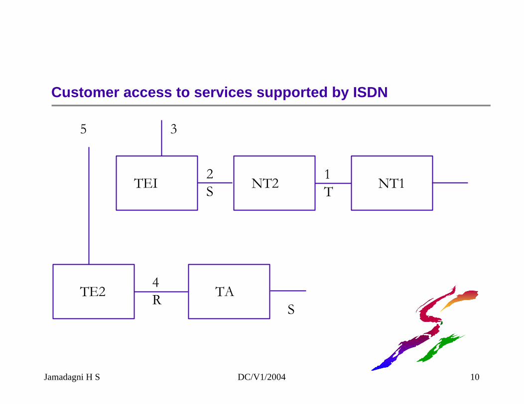
Customer access to services supported by ISDN
TEI NT2 NT1
TE2 TA
5
4R
S
3
2S
1T
Jamadagni H S DC/V1/2004 10
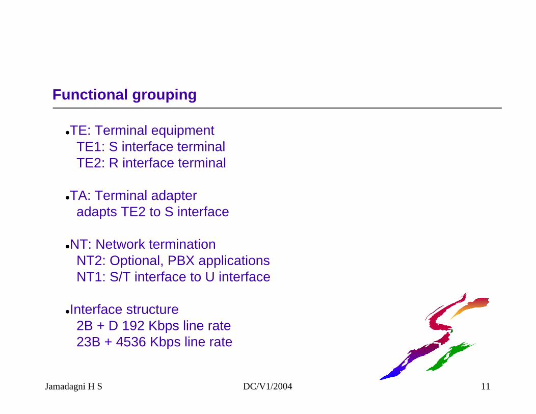
Functional grouping
TE: Terminal equipmentTE1: S interface terminalTE2: R interface terminal
TA: Terminal adapteradapts TE2 to S interface
NT: Network terminationNT2: Optional, PBX applicationsNT1: S/T interface to U interface
Interface structure2B + D 192 Kbps line rate23B + 4536 Kbps line rate
Jamadagni H S DC/V1/2004 11
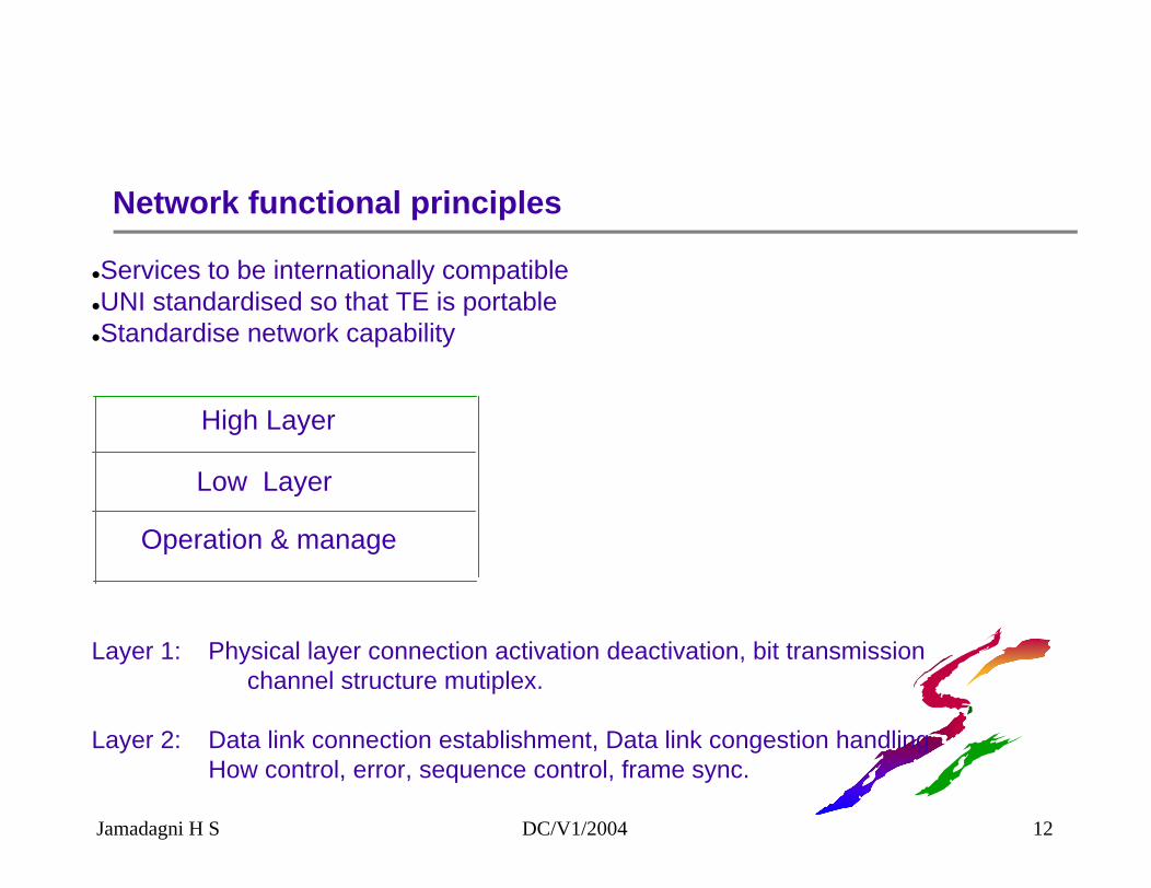
Network functional principles
Services to be internationally compatibleUNI standardised so that TE is portableStandardise network capability
High Layer
Low Layer
Operation & manage
Layer 1: Physical layer connection activation deactivation, bit transmissionchannel structure mutiplex.
Layer 2: Data link connection establishment, Data link congestion handlingHow control, error, sequence control, frame sync.
Jamadagni H S DC/V1/2004 12
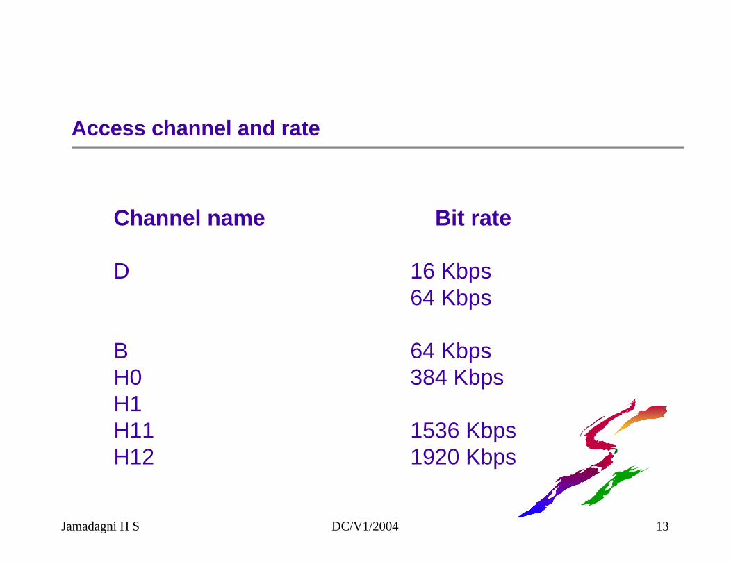
Access channel and rate
Channel name Bit rate
D 16 Kbps64 Kbps
B 64 KbpsH0 384 KbpsH1H11 1536 KbpsH12 1920 Kbps
Jamadagni H S DC/V1/2004 13
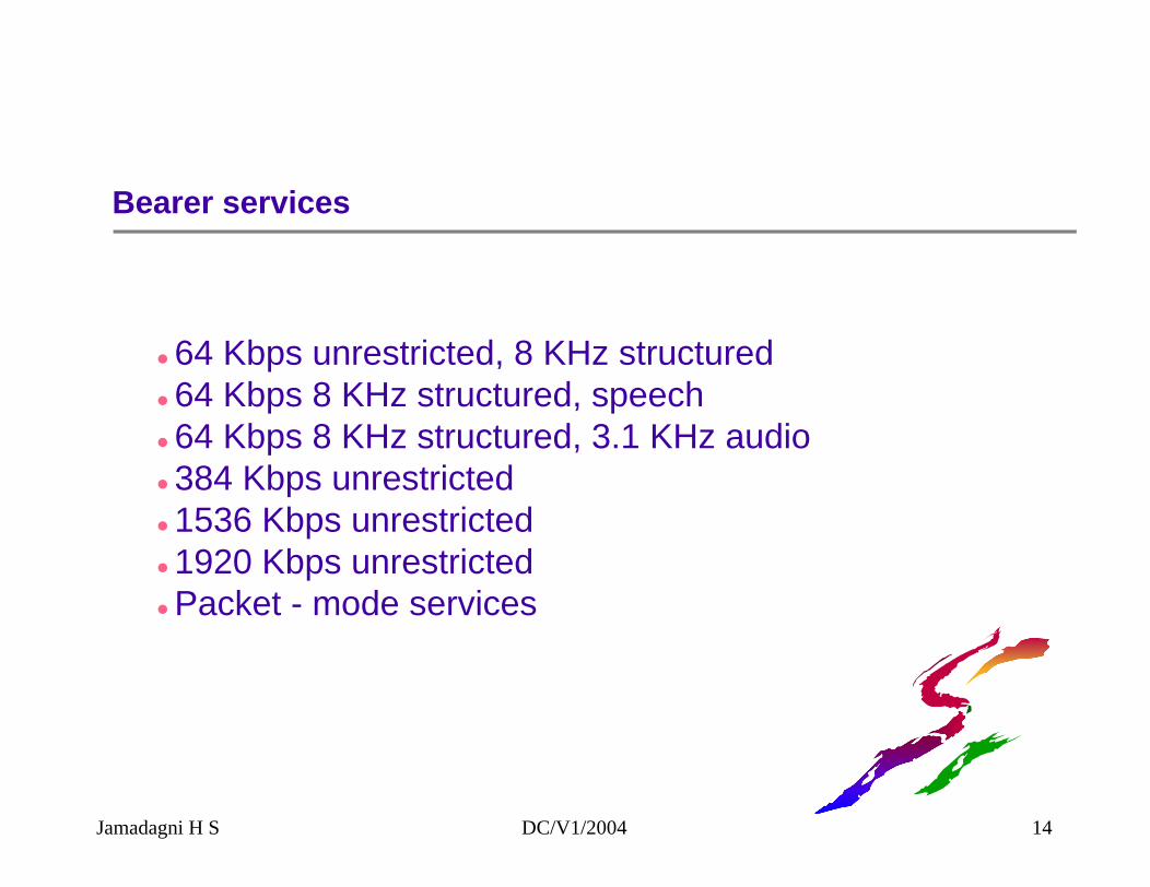
Bearer services
64 Kbps unrestricted, 8 KHz structured64 Kbps 8 KHz structured, speech64 Kbps 8 KHz structured, 3.1 KHz audio384 Kbps unrestricted1536 Kbps unrestricted1920 Kbps unrestrictedPacket - mode services
Jamadagni H S DC/V1/2004 14
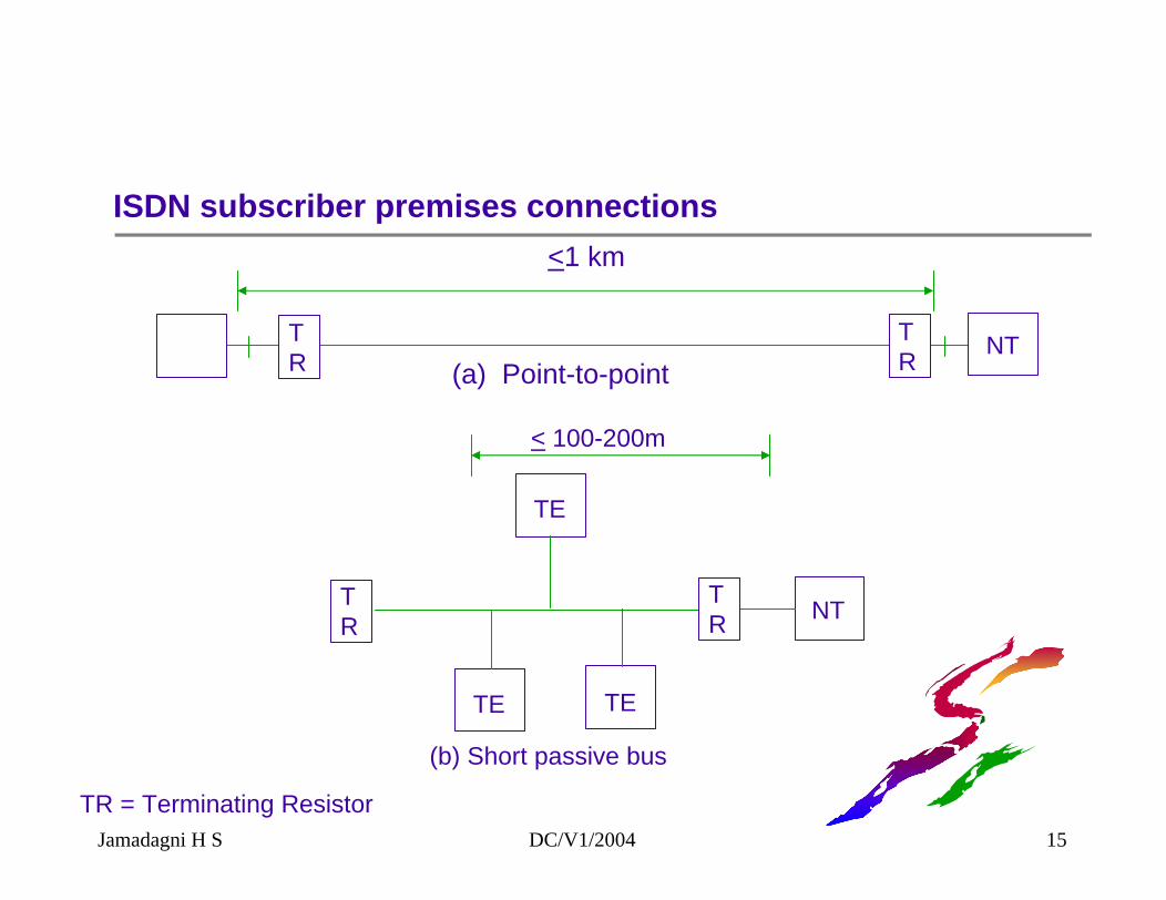
ISDN subscriber premises connections
TE NTTR
TR (a) Point-to-point
TE
TETE
NTTR
TR
< 100-200m
(b) Short passive bus
<1 km
TR = Terminating ResistorJamadagni H S DC/V1/2004 15
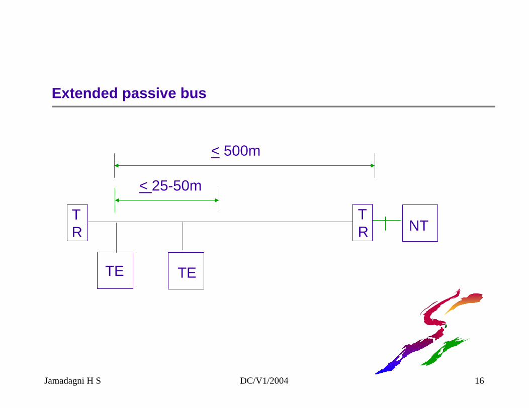
Extended passive bus
TETE
NTTR
TR
< 500m
< 25-50m
Jamadagni H S DC/V1/2004 16
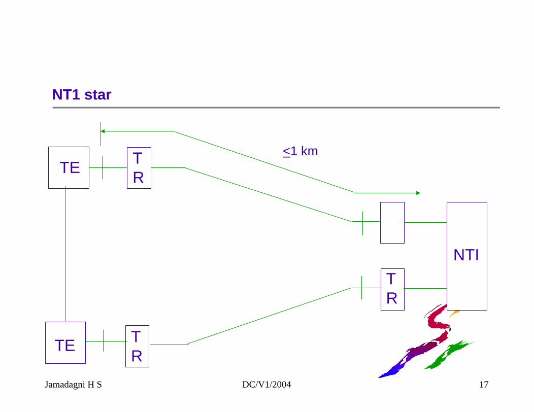
NT1 star
TR
TRTE
TR
TRTE
NTI
<1 km
Jamadagni H S DC/V1/2004 17
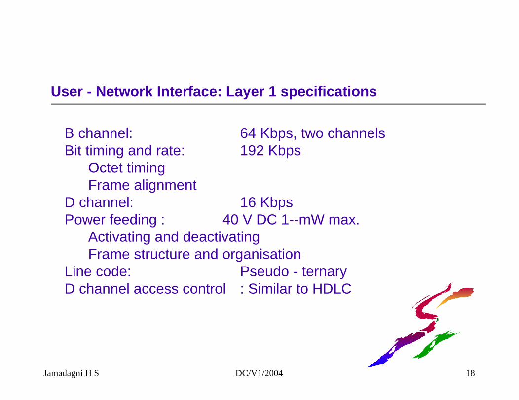
User - Network Interface: Layer 1 specifications
B channel: 64 Kbps, two channelsBit timing and rate: 192 Kbps
Octet timingFrame alignment
D channel: 16 KbpsPower feeding : 40 V DC 1--mW max.
Activating and deactivatingFrame structure and organisation
Line code: Pseudo - ternaryD channel access control : Similar to HDLC
Jamadagni H S DC/V1/2004 18
Layer 1 functions
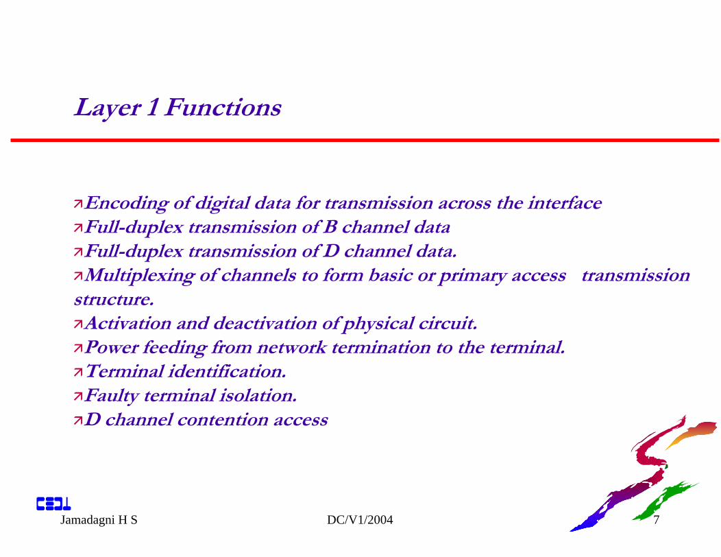
Encoding of digital data for transmission across the interface.Full-duplex transmission of B channel dataFull-duplex transmission of D channel data.Multiplexing of channels to form basic or primary access transmission
structure.Activation and deactivation of physical circuit.Power feeding from network termination to the terminal.Terminal identification.Faulty terminal isolation.D channel contention access
Jamadagni H S DC/V1/2004 19
ISDN Layer 2
Traffic over D channel (control Info and data over D) Q 921
Q921 services
Convey user Info between layers entities using D channelSupport multiple terminals at user-NW installationMultiple layer 3 entity support two types of transferUnacknowledged transfer (un no: frames)Acknowledged transfer (like X 25) HDLC
Jamadagni H S DC/V1/2004 20
Function of other layers
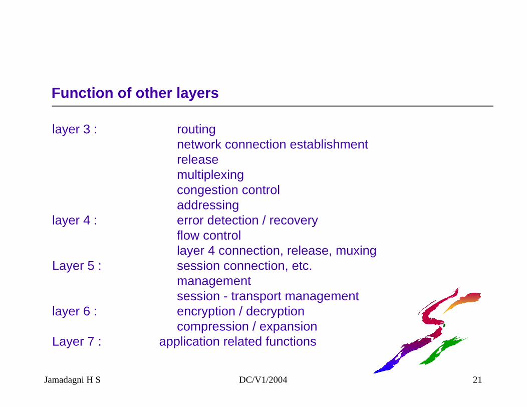
layer 3 : routingnetwork connection establishmentreleasemultiplexingcongestion controladdressing
layer 4 : error detection / recoveryflow controllayer 4 connection, release, muxing
Layer 5 : session connection, etc.managementsession - transport management
layer 6 : encryption / decryptioncompression / expansion
Layer 7 : application related functions
Jamadagni H S DC/V1/2004 21
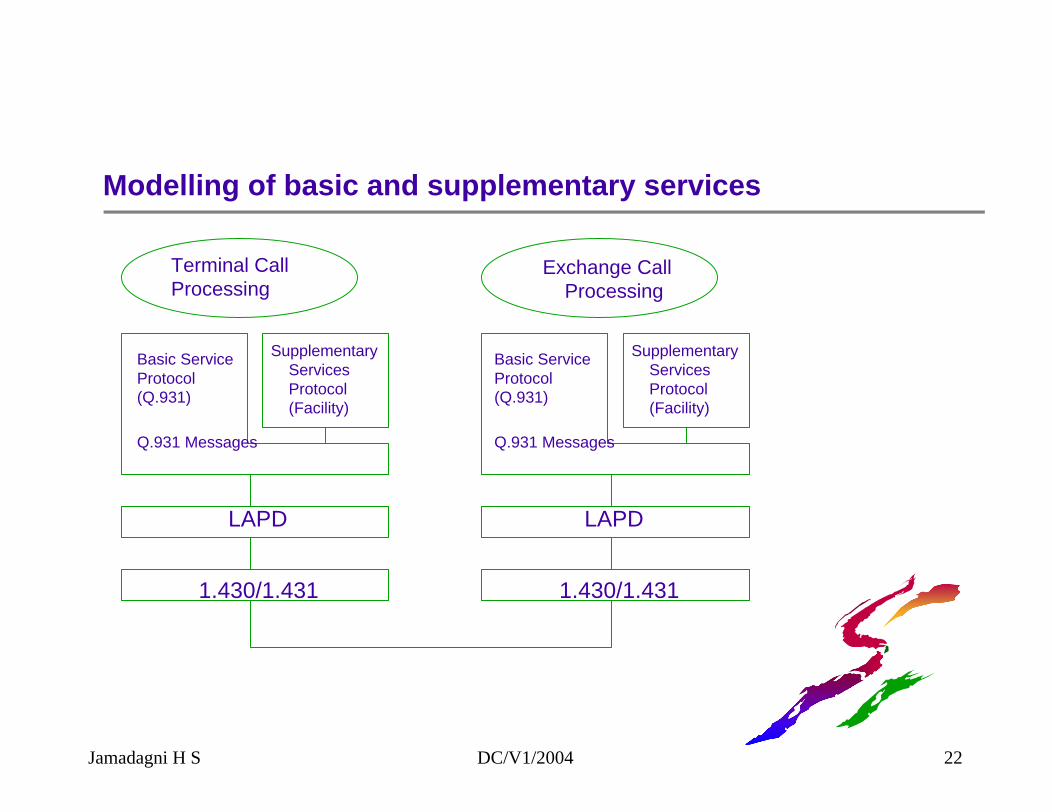
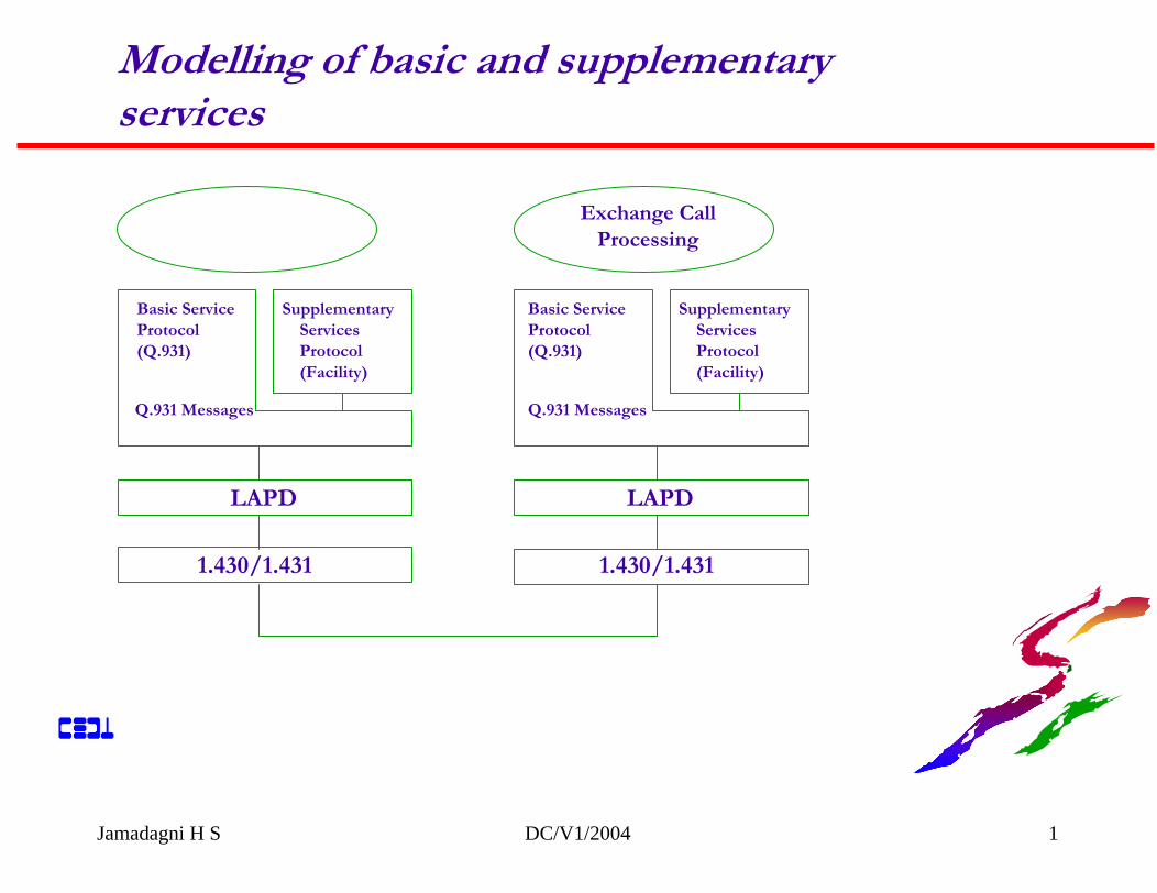
Modelling of basic and supplementary services
Terminal CallProcessing
Basic ServiceProtocol(Q.931)
SupplementaryServicesProtocol(Facility)
Q.931 Messages
LAPD
1.430/1.431
Exchange CallProcessing
Basic ServiceProtocol(Q.931)
SupplementaryServicesProtocol(Facility)
Q.931 Messages
LAPD
1.430/1.431
Jamadagni H S DC/V1/2004 22
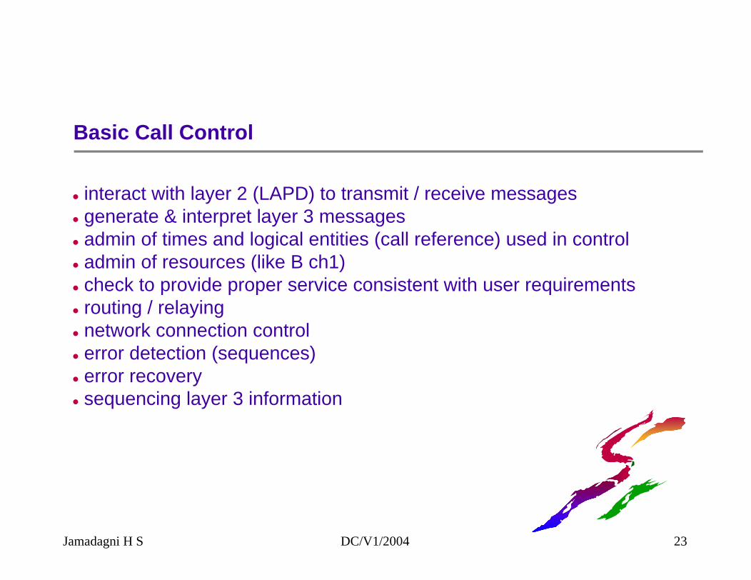
Basic Call Control
interact with layer 2 (LAPD) to transmit / receive messagesgenerate & interpret layer 3 messagesadmin of times and logical entities (call reference) used in controladmin of resources (like B ch1)check to provide proper service consistent with user requirementsrouting / relayingnetwork connection controlerror detection (sequences)error recoverysequencing layer 3 information
Jamadagni H S DC/V1/2004 23
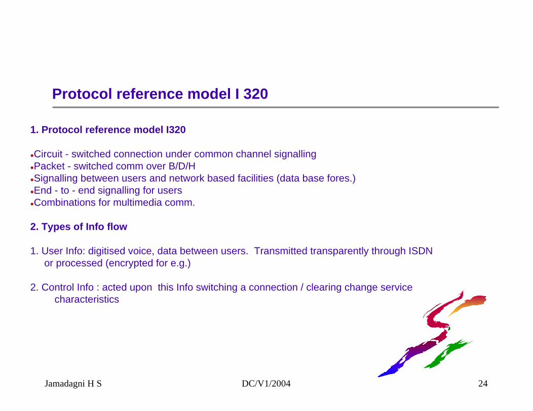
Protocol reference model I 320
1. Protocol reference model I320
Circuit - switched connection under common channel signallingPacket - switched comm over B/D/HSignalling between users and network based facilities (data base fores.)End - to - end signalling for users Combinations for multimedia comm.
2. Types of Info flow
1. User Info: digitised voice, data between users. Transmitted transparently through ISDNor processed (encrypted for e.g.)
2. Control Info : acted upon this Info switching a connection / clearing change service characteristics
Jamadagni H S DC/V1/2004 24
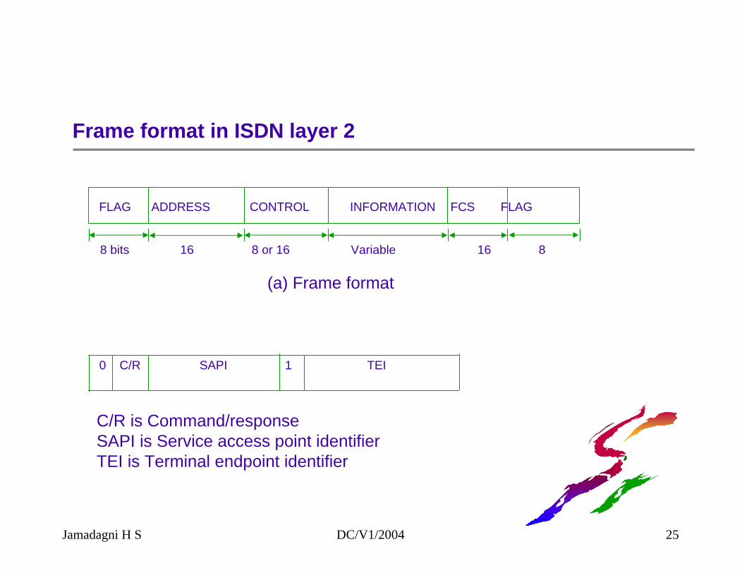
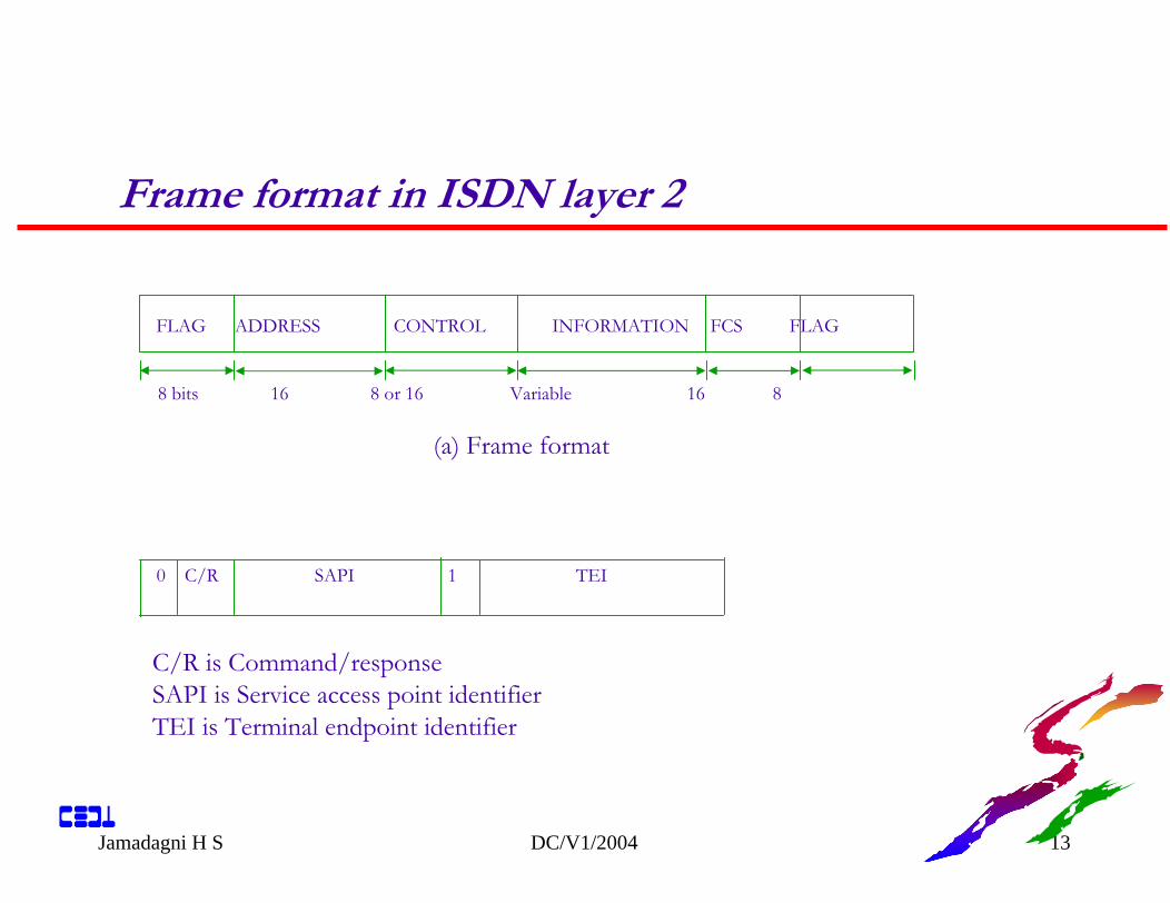
Frame format in ISDN layer 2
FLAG ADDRESS CONTROL INFORMATION FCS FLAG
8 bits 16 8 or 16 Variable 16 8
(a) Frame format
0 C/R SAPI 1 TEI
C/R is Command/responseSAPI is Service access point identifierTEI is Terminal endpoint identifier
Jamadagni H S DC/V1/2004 25
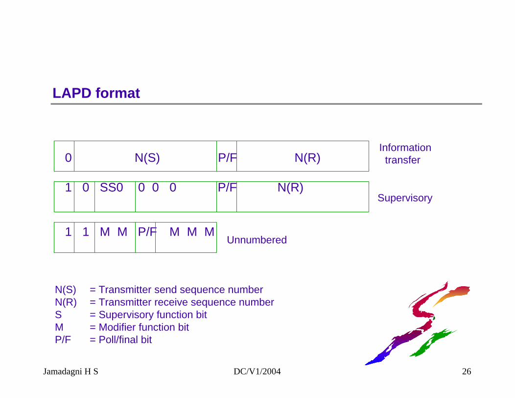
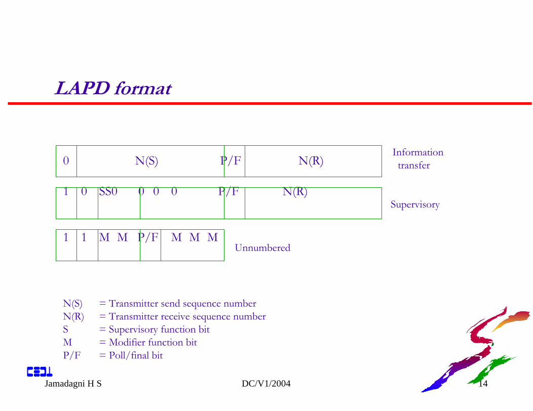
LAPD format
0 N(S) P/F N(R)
1 0 SS0 0 0 0 P/F N(R)
1 1 M M P/F M M M
Informationtransfer
Supervisory
Unnumbered
N(S) = Transmitter send sequence numberN(R) = Transmitter receive sequence numberS = Supervisory function bitM = Modifier function bitP/F = Poll/final bit
Jamadagni H S DC/V1/2004 26
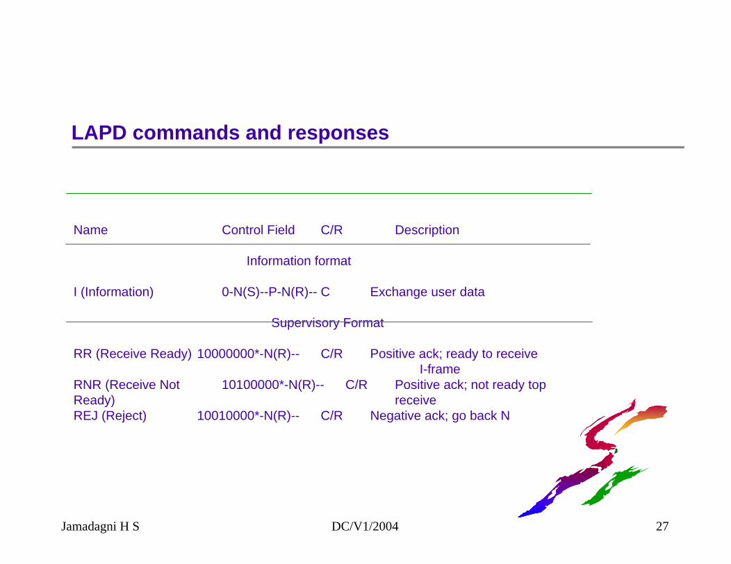
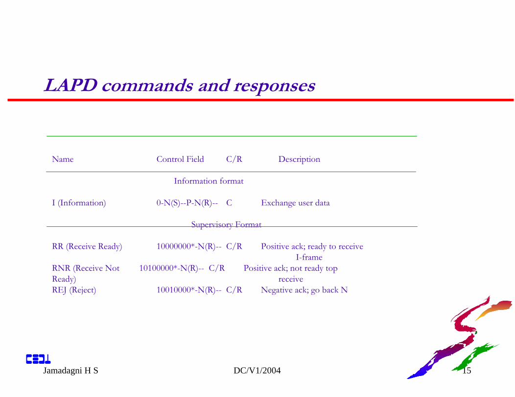
Name Control Field C/R Description
Information format
I (Information) 0-N(S)--P-N(R)-- C Exchange user data
Supervisory Format
RR (Receive Ready) 10000000*-N(R)-- C/R Positive ack; ready to receive I-frame
RNR (Receive Not 10100000*-N(R)-- C/R Positive ack; not ready topReady) receiveREJ (Reject) 10010000*-N(R)-- C/R Negative ack; go back N
LAPD commands and responses
Jamadagni H S DC/V1/2004 27
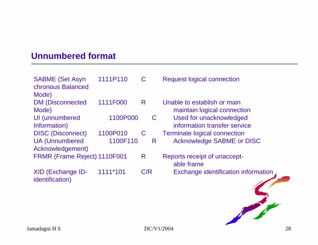
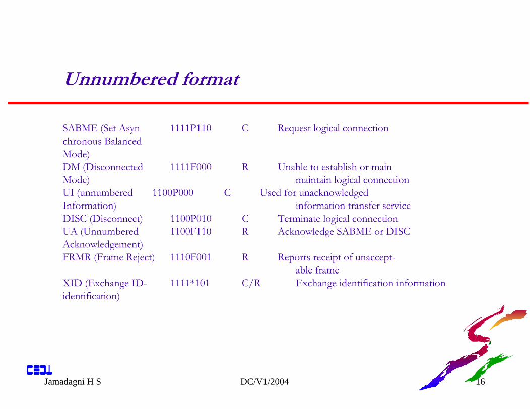
Unnumbered format
SABME (Set Asyn 1111P110 C Request logical connectionchronous BalancedMode)DM (Disconnected 1111F000 R Unable to establish or mainMode) maintain logical connectionUI (unnumbered 1100P000 C Used for unacknowledgedInformation) information transfer serviceDISC (Disconnect) 1100P010 C Terminate logical connectionUA (Unnumbered 1100F110 R Acknowledge SABME or DISCAcknowledgement)FRMR (Frame Reject) 1110F001 R Reports receipt of unaccept-
able frameXID (Exchange ID- 1111*101 C/R Exchange identification informationidentification)
Jamadagni H S DC/V1/2004 28
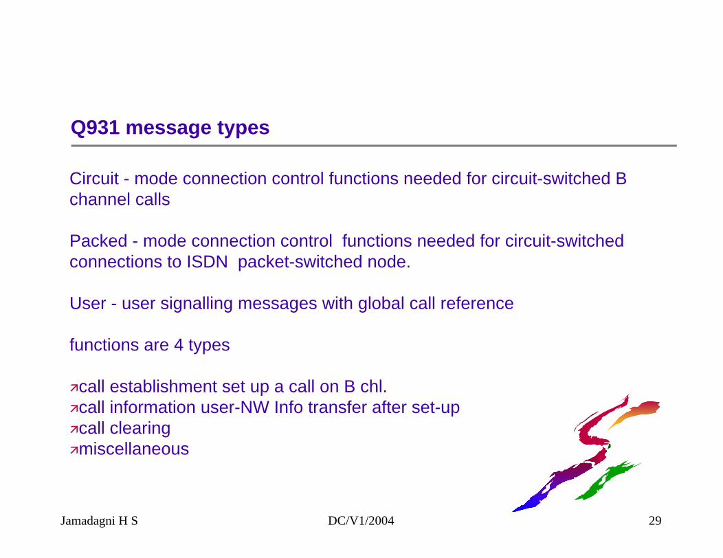
Q931 message types
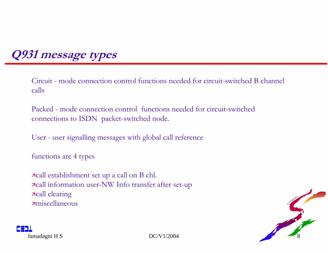
Circuit - mode connection control functions needed for circuit-switched B channel calls
Packed - mode connection control functions needed for circuit-switched connections to ISDN packet-switched node.
User - user signalling messages with global call reference
functions are 4 types
call establishment set up a call on B chl.call information user-NW Info transfer after set-upcall clearingmiscellaneous
Jamadagni H S DC/V1/2004 29
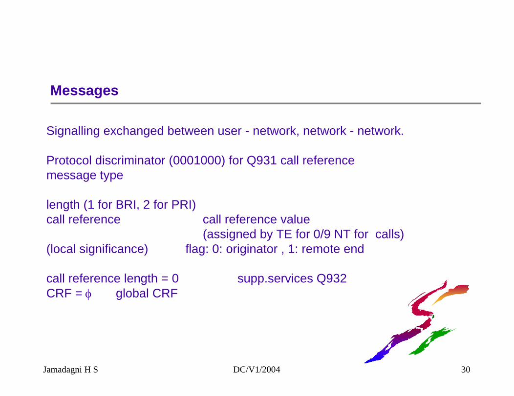
Messages
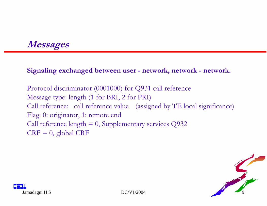
Signalling exchanged between user - network, network - network.
Protocol discriminator (0001000) for Q931 call referencemessage type
length (1 for BRI, 2 for PRI)call reference call reference value
(assigned by TE for 0/9 NT for calls)(local significance) flag: 0: originator , 1: remote end
call reference length = 0 supp.services Q932CRF = φ global CRF
Jamadagni H S DC/V1/2004 30
SAPI and TEI assignments
Jamadagni H S DC/V1/2004 31
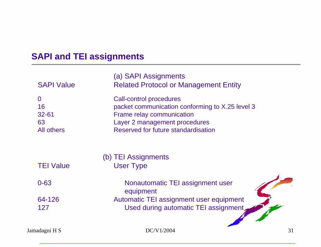
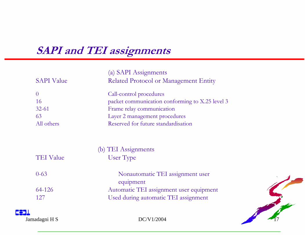
(a) SAPI AssignmentsSAPI Value Related Protocol or Management Entity
0 Call-control procedures16 packet communication conforming to X.25 level 332-61 Frame relay communication63 Layer 2 management proceduresAll others Reserved for future standardisation
(b) TEI AssignmentsTEI Value User Type
0-63 Nonautomatic TEI assignment userequipment
64-126 Automatic TEI assignment user equipment127 Used during automatic TEI assignment
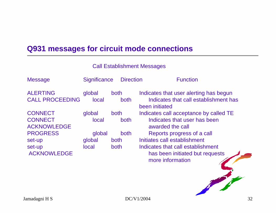
Q931 messages for circuit mode connections
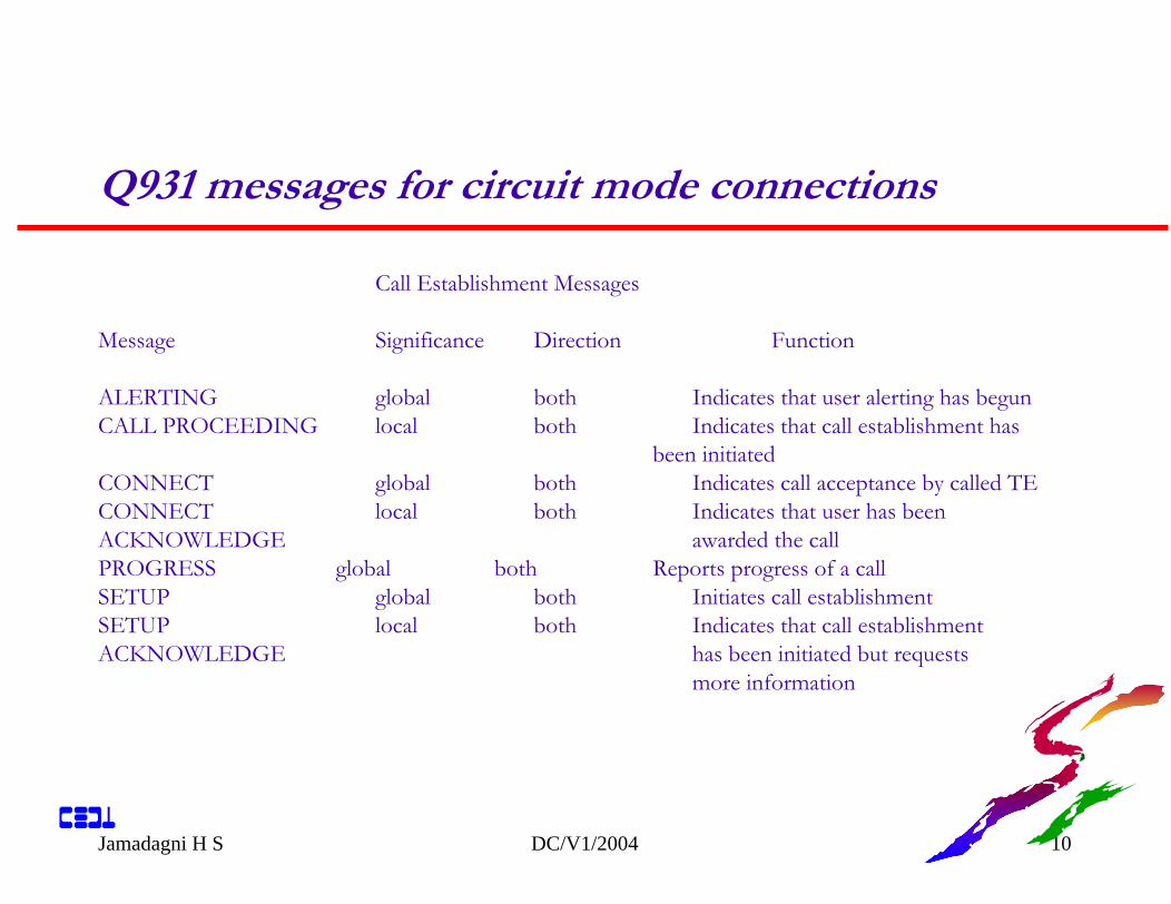
Call Establishment Messages
Message Significance Direction Function
ALERTING global both Indicates that user alerting has begunCALL PROCEEDING local both Indicates that call establishment has
been initiatedCONNECT global both Indicates call acceptance by called TECONNECT local both Indicates that user has been ACKNOWLEDGE awarded the callPROGRESS global both Reports progress of a callset-up global both Initiates call establishmentset-up local both Indicates that call establishmentACKNOWLEDGE has been initiated but requests
more information
Jamadagni H S DC/V1/2004 32
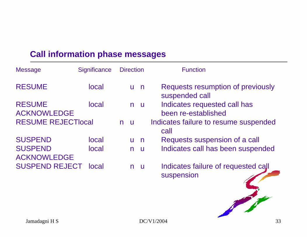
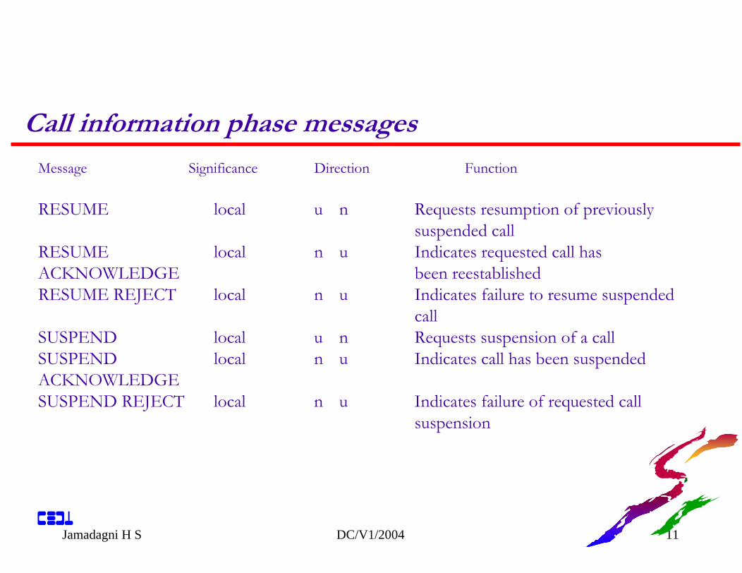
Call information phase messagesMessage Significance Direction Function
RESUME local u n Requests resumption of previously suspended call
RESUME local n u Indicates requested call has ACKNOWLEDGE been re-establishedRESUME REJECTlocal n u Indicates failure to resume suspended
callSUSPEND local u n Requests suspension of a call SUSPEND local n u Indicates call has been suspendedACKNOWLEDGESUSPEND REJECT local n u Indicates failure of requested call
suspension
Jamadagni H S DC/V1/2004 33
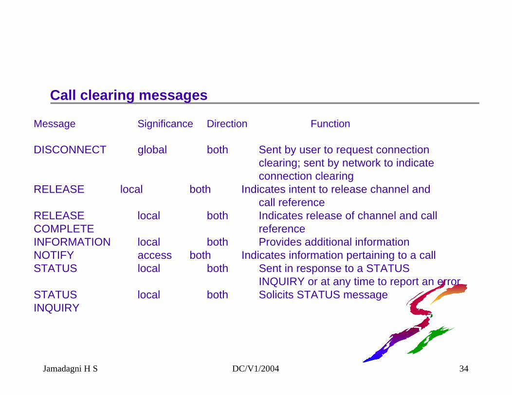
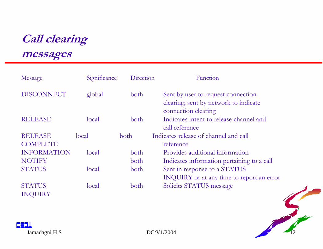
Message Significance Direction Function
DISCONNECT global both Sent by user to request connectionclearing; sent by network to indicateconnection clearing
RELEASE local both Indicates intent to release channel andcall reference
RELEASE local both Indicates release of channel and callCOMPLETE referenceINFORMATION local both Provides additional informationNOTIFY access both Indicates information pertaining to a callSTATUS local both Sent in response to a STATUS
INQUIRY or at any time to report an errorSTATUS local both Solicits STATUS messageINQUIRY
Call clearing messages
Jamadagni H S DC/V1/2004 34
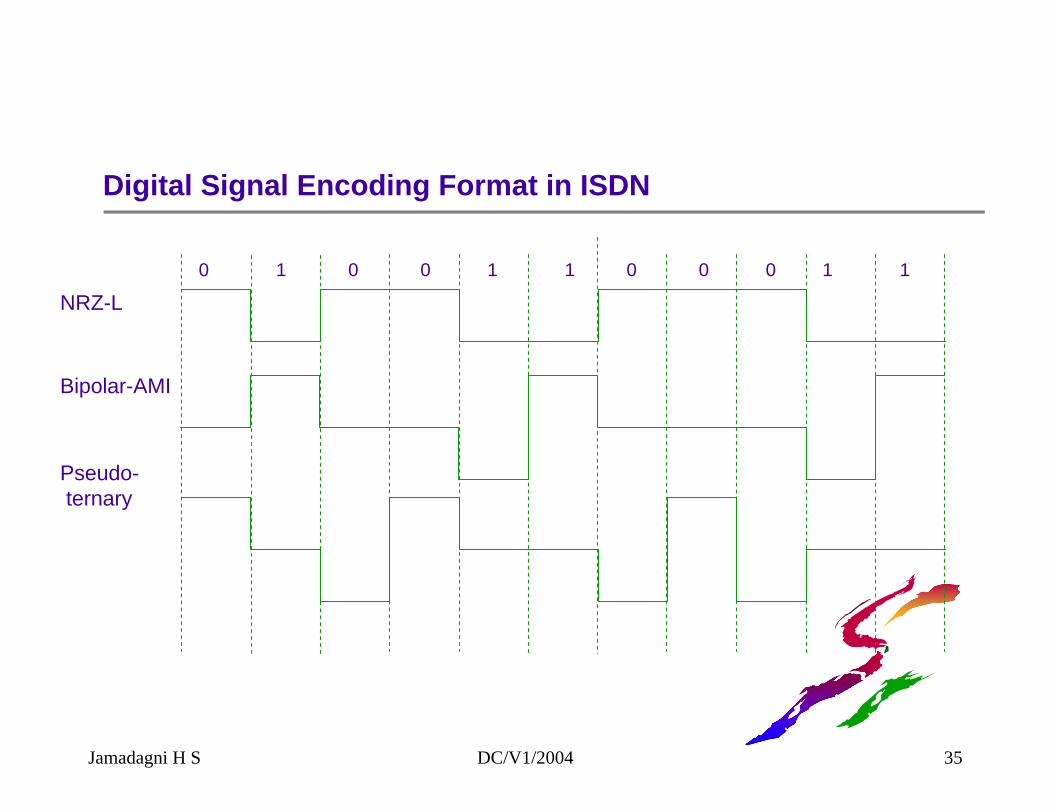
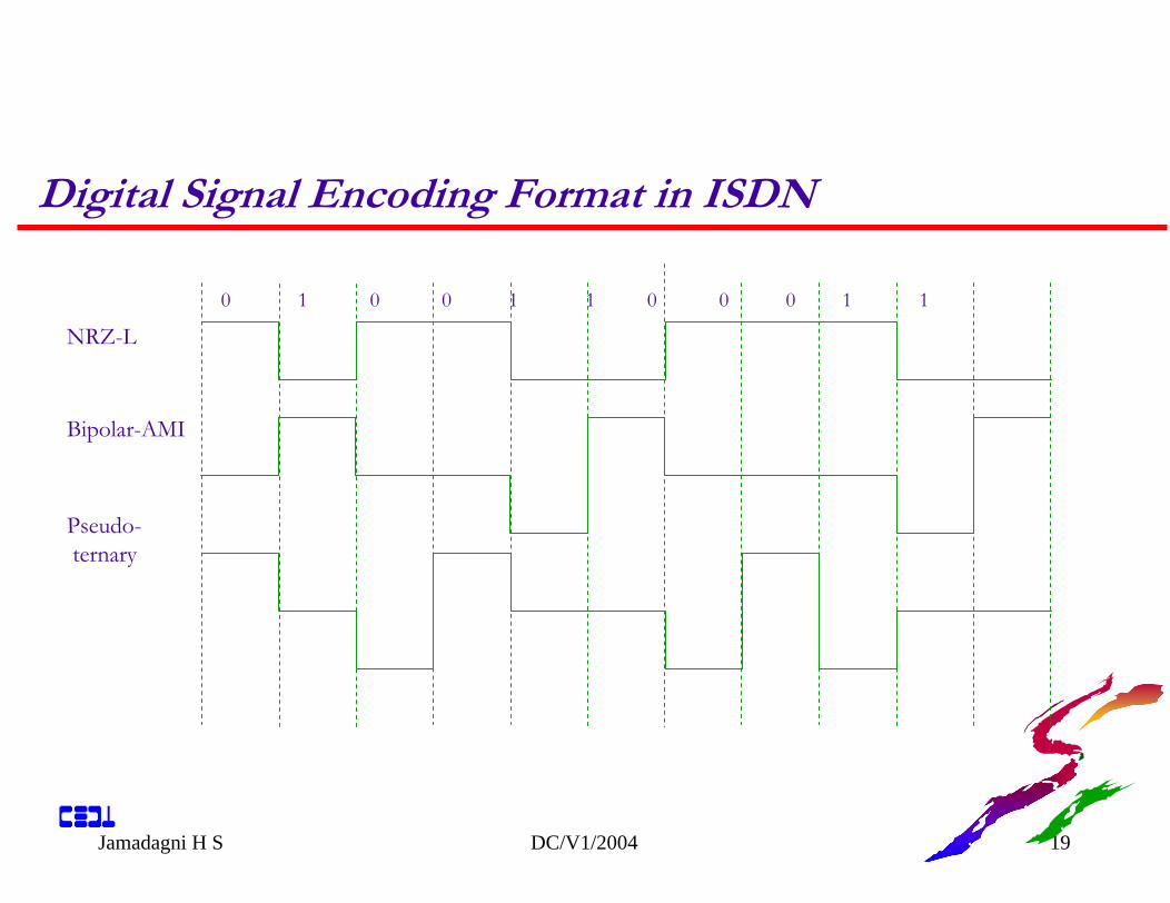
Digital Signal Encoding Format in ISDN
NRZ-L
Bipolar-AMI
Pseudo-ternary
0 1 0 0 1 1 0 0 0 1 1
Jamadagni H S DC/V1/2004 35
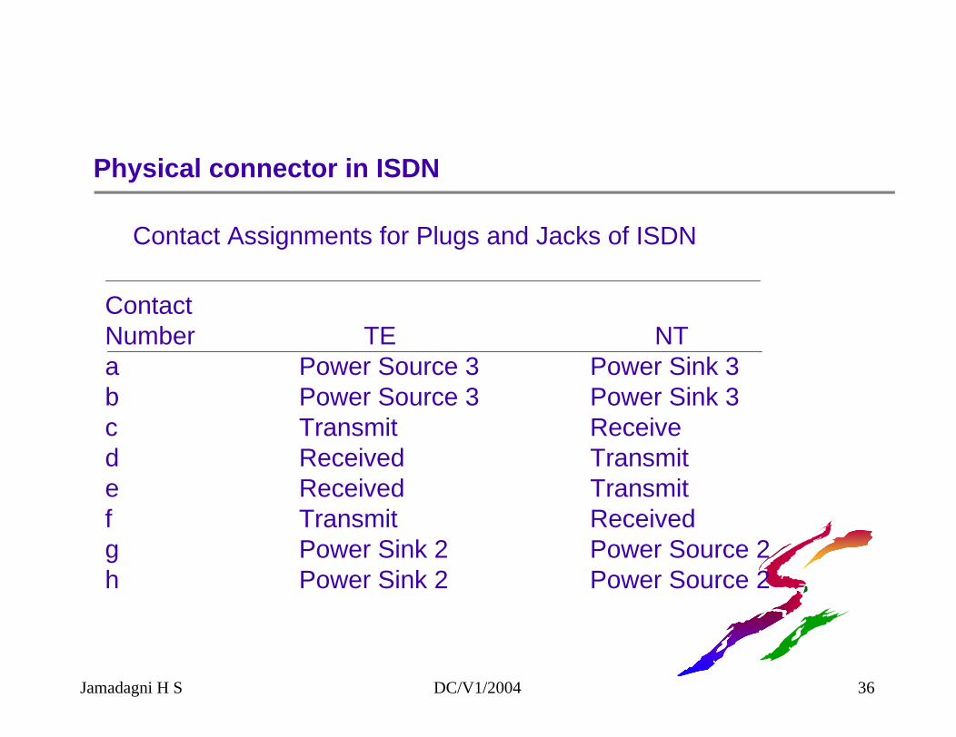
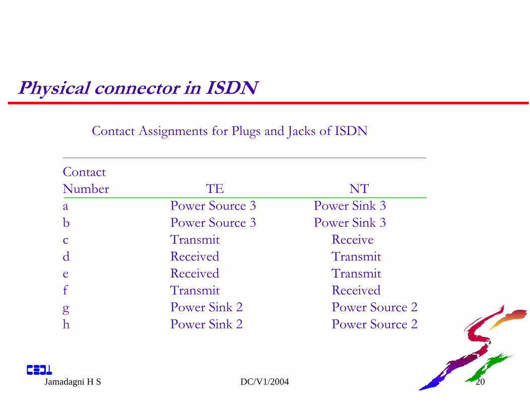
Physical connector in ISDN
Contact Assignments for Plugs and Jacks of ISDN
ContactNumber TE NTa Power Source 3 Power Sink 3b Power Source 3 Power Sink 3c Transmit Received Received Transmite Received Transmitf Transmit Receivedg Power Sink 2 Power Source 2h Power Sink 2 Power Source 2
Jamadagni H S DC/V1/2004 36
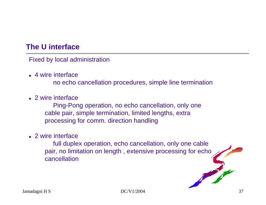
The U interfaceFixed by local administration
4 wire interface no echo cancellation procedures, simple line termination
2 wire interfacePing-Pong operation, no echo cancellation, only one
cable pair, simple termination, limited lengths, extra processing for comm. direction handling
2 wire interfacefull duplex operation, echo cancellation, only one cable
pair, no limitation on length , extensive processing for echo cancellation
Jamadagni H S DC/V1/2004 37
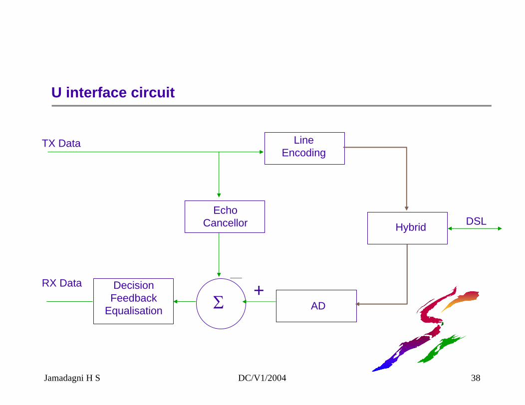
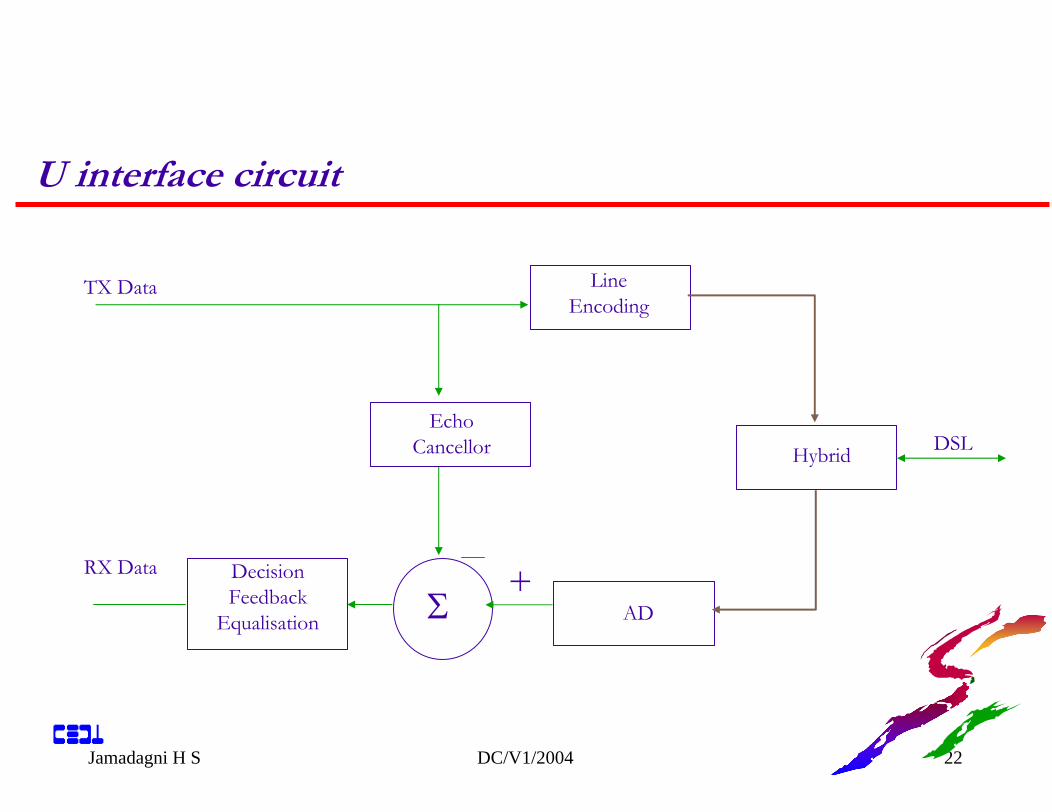
U interface circuit
+RX Data DecisionFeedback
Equalisation
LineEncoding
EchoCancellor Hybrid DSL
TX Data
Σ AD
Jamadagni H S DC/V1/2004 38
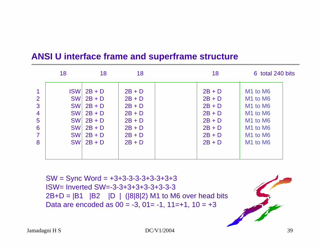
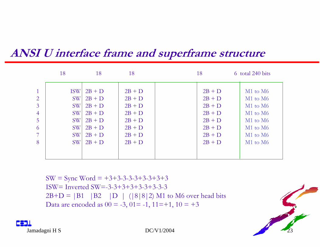
ANSI U interface frame and superframe structure
ISWSWSWSWSWSWSWSW
12345678
2B + D2B + D2B + D2B + D2B + D2B + D2B + D2B + D
2B + D2B + D2B + D2B + D2B + D2B + D2B + D2B + D
2B + D2B + D2B + D2B + D2B + D2B + D2B + D2B + D
18 18 18 18 6 total 240 bits
M1 to M6M1 to M6M1 to M6M1 to M6M1 to M6M1 to M6M1 to M6M1 to M6
SW = Sync Word = +3+3-3-3-3+3-3+3+3ISW= Inverted SW=-3-3+3+3+3-3+3-3-32B+D = |B1 |B2 |D | (|8|8|2) M1 to M6 over head bitsData are encoded as 00 = -3, 01= -1, 11=+1, 10 = +3
Jamadagni H S DC/V1/2004 39

TEI and SAPI assignment
Jamadagni H S DC/V1/2004 40
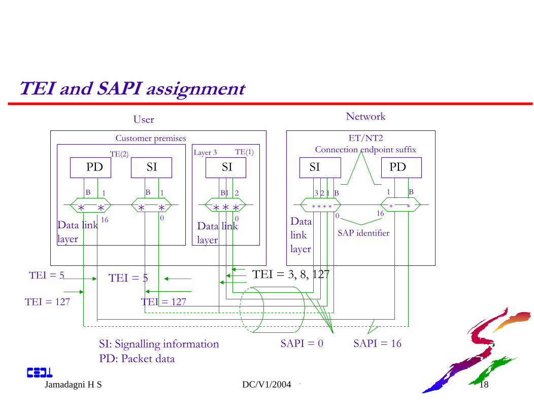
* ** * * ** * ** * * *
SAPI = 0 SAPI = 16
SAP identifier
Datalinklayer
SI: Signalling informationPD: Packet data
Data linklayer
Data linklayer
TEI = 127
TEI = 5
TEI = 127
TEI = 5
B B1B1 1 2 3 2 1 B 1 B
UserET/NT2
Connection endpoint suffixCustomer premises
Network
Layer 3TE(2) TE(1)
0 1616 0 0
PDPD SI
SI
SI
TEI = 3, 8, 127
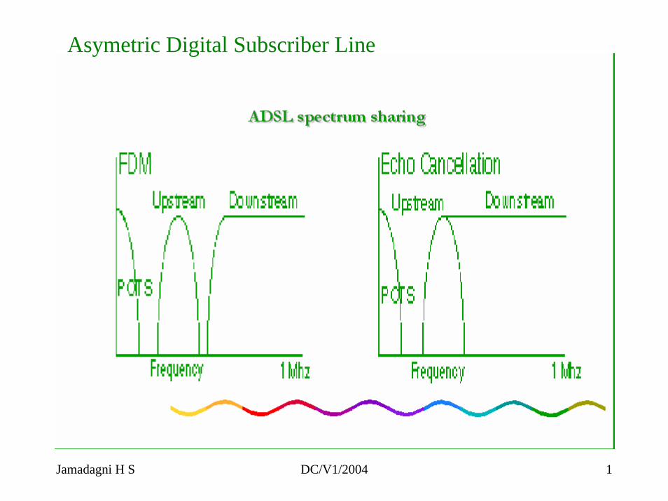
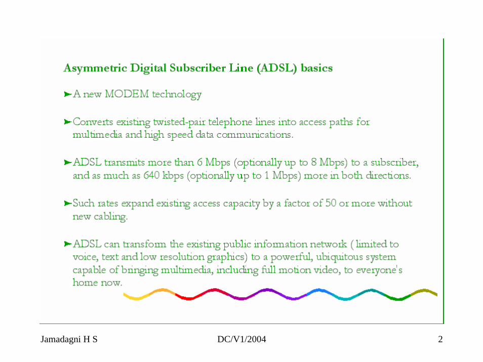
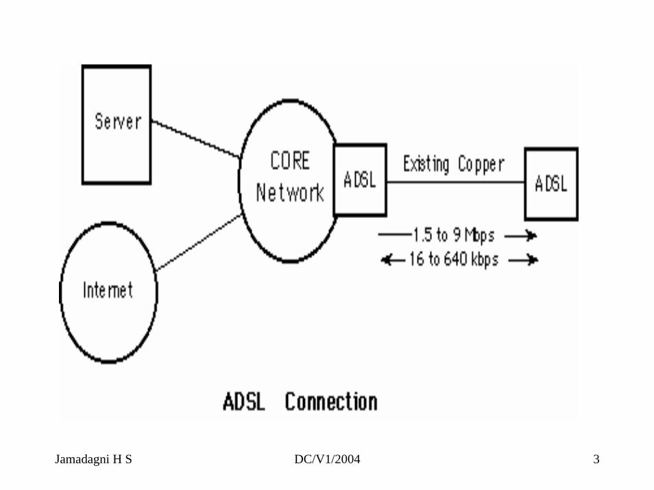
Asymetric Digital Subscriber Line
Jamadagni H S DC/V1/2004 1
Jamadagni H S DC/V1/2004 2
Jamadagni H S DC/V1/2004 3
ADSL will play a crucial role over the next ten or more years for delivering information in video and multimedia formats. New broadband cabling will take decades to reach all prospective subscribers.
Success of these new services will depend upon reaching as many subscribers as possible during the first few years.
By bringing movies, television, video catalogs, remote CD-ROMs, corporate LANs, and the Internet into homes and small businesses, ADSL will make these markets viable, and profitable, for telephone companies and application suppliers alike.
ADSL basics (contd 1)
Jamadagni H S DC/V1/2004 4
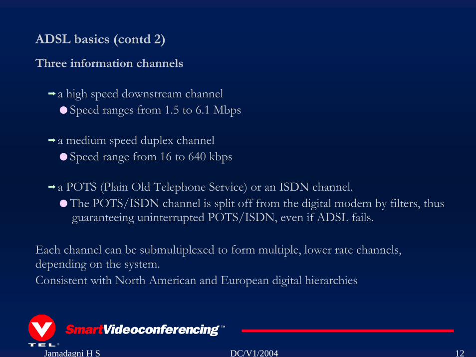
ADSL basics (contd 2)
Three information channels
a high speed downstream channelSpeed ranges from 1.5 to 6.1 Mbps
a medium speed duplex channelSpeed range from 16 to 640 kbps
a POTS (Plain Old Telephone Service) or an ISDN channel. The POTS/ISDN channel is split off from the digital modem by filters, thus guaranteeing uninterrupted POTS/ISDN, even if ADSL fails.
Each channel can be submultiplexed to form multiple, lower rate channels, depending on the system.Consistent with North American and European digital hierarchies
Jamadagni H S DC/V1/2004 5
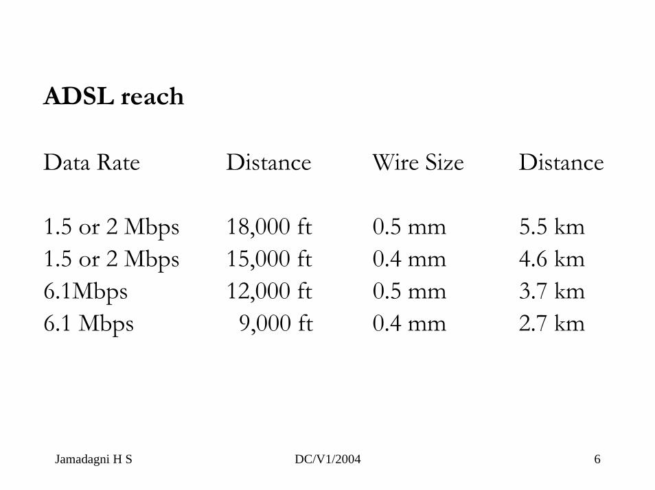
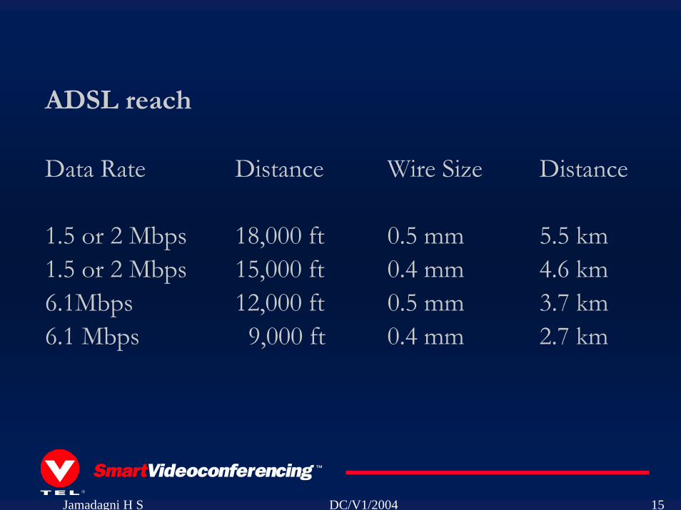
ADSL reach
Data Rate Distance Wire Size Distance
1.5 or 2 Mbps 18,000 ft 0.5 mm 5.5 km 1.5 or 2 Mbps 15,000 ft 0.4 mm 4.6 km 6.1Mbps 12,000 ft 0.5 mm 3.7 km 6.1 Mbps 9,000 ft 0.4 mm 2.7 km
Jamadagni H S DC/V1/2004 6
Jamadagni H S DC/V1/2004 7
Jamadagni H S DC/V1/2004 1
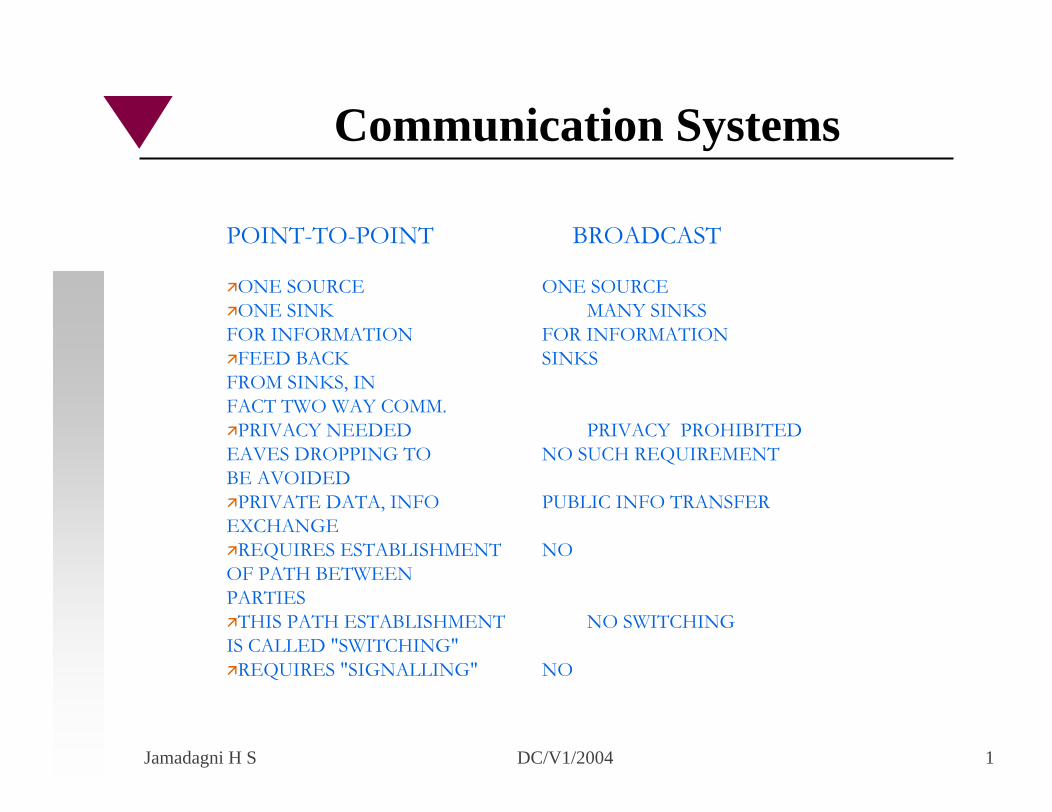
POINT-TO-POINT BROADCAST
ONE SOURCE ONE SOURCEONE SINK MANY SINKS
FOR INFORMATION FOR INFORMATIONFEED BACK SINKS
FROM SINKS, INFACT TWO WAY COMM.
PRIVACY NEEDED PRIVACY PROHIBITEDEAVES DROPPING TO NO SUCH REQUIREMENTBE AVOIDED
PRIVATE DATA, INFO PUBLIC INFO TRANSFEREXCHANGE
REQUIRES ESTABLISHMENT NOOF PATH BETWEENPARTIES
THIS PATH ESTABLISHMENT NO SWITCHINGIS CALLED "SWITCHING"
REQUIRES "SIGNALLING" NO
Communication Systems
Jamadagni H S DC/V1/2004 2
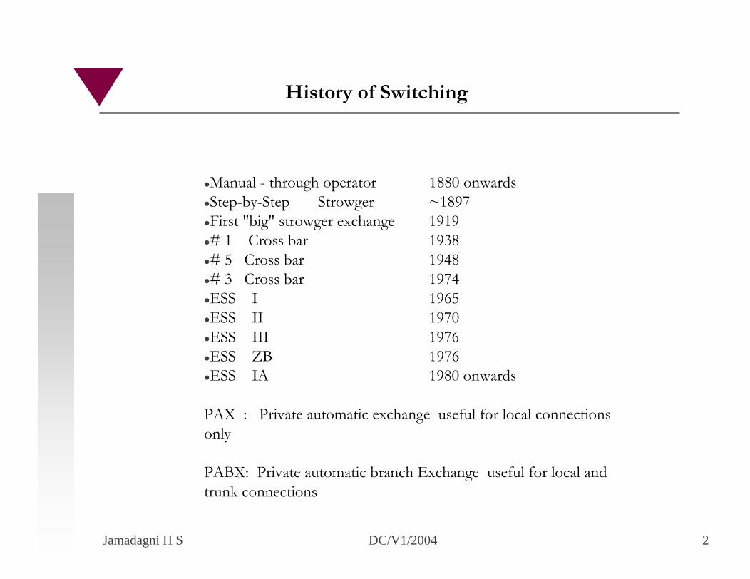
Manual - through operator 1880 onwardsStep-by-Step Strowger ~1897First "big" strowger exchange 1919# 1 Cross bar 1938# 5 Cross bar 1948# 3 Cross bar 1974ESS I 1965ESS II 1970ESS III 1976ESS ZB 1976ESS IA 1980 onwards
PAX : Private automatic exchange useful for local connections only
PABX: Private automatic branch Exchange useful for local and trunk connections
History of Switching
Jamadagni H S DC/V1/2004 3
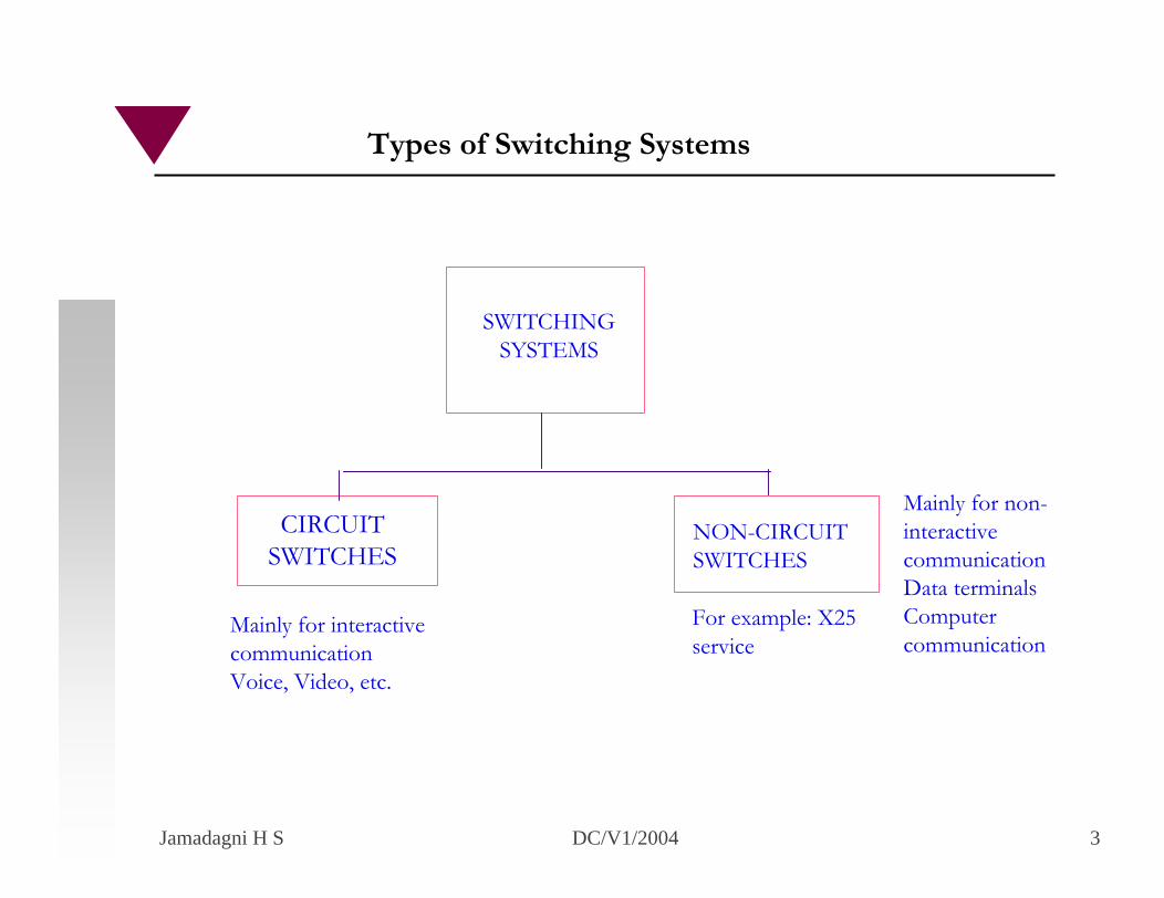
SWITCHINGSYSTEMS
NON-CIRCUITSWITCHES
CIRCUITSWITCHES
Mainly for interactivecommunicationVoice, Video, etc.
Mainly for non-interactivecommunicationData terminalsComputer communication
Types of Switching Systems
For example: X25 service
Jamadagni H S DC/V1/2004 4
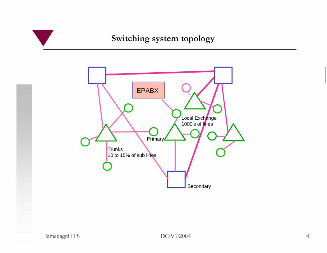
EPABX
Trunks10 to 15% of sub lines
Primary
Local Exchange1000's of lines
Secondary
Switching system topology
Jamadagni H S DC/V1/2004 5
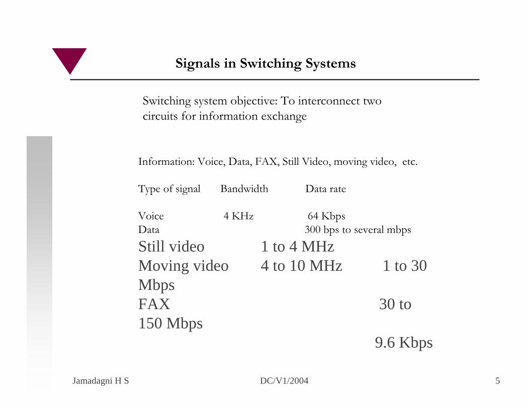
Switching system objective: To interconnect twocircuits for information exchange
Information: Voice, Data, FAX, Still Video, moving video, etc.
Type of signal Bandwidth Data rate
Voice 4 KHz 64 KbpsData 300 bps to several mbps
Still video 1 to 4 MHz Moving video 4 to 10 MHz 1 to 30 MbpsFAX 30 to 150 Mbps
9.6 Kbps
Signals in Switching Systems
Jamadagni H S DC/V1/2004 6
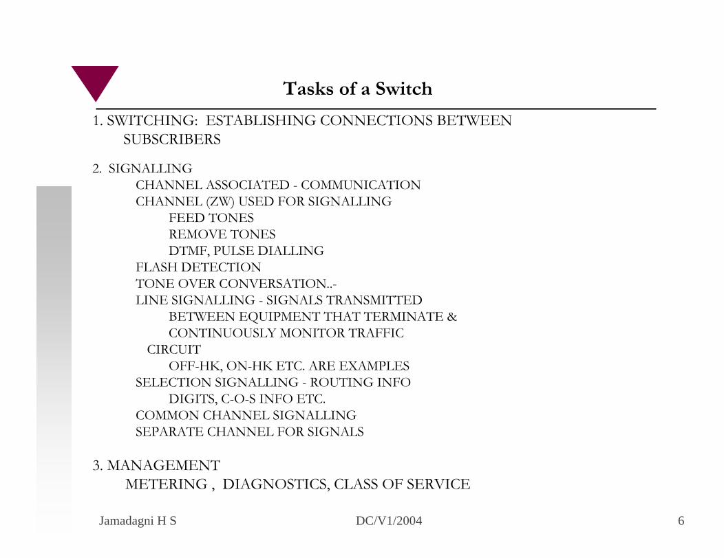
2. SIGNALLINGCHANNEL ASSOCIATED - COMMUNICATIONCHANNEL (ZW) USED FOR SIGNALLING
FEED TONESREMOVE TONESDTMF, PULSE DIALLING
FLASH DETECTIONTONE OVER CONVERSATION..-LINE SIGNALLING - SIGNALS TRANSMITTED
BETWEEN EQUIPMENT THAT TERMINATE &CONTINUOUSLY MONITOR TRAFFIC
CIRCUITOFF-HK, ON-HK ETC. ARE EXAMPLES
SELECTION SIGNALLING - ROUTING INFODIGITS, C-O-S INFO ETC.
COMMON CHANNEL SIGNALLINGSEPARATE CHANNEL FOR SIGNALS
Tasks of a Switch
1. SWITCHING: ESTABLISHING CONNECTIONS BETWEEN SUBSCRIBERS
3. MANAGEMENT METERING , DIAGNOSTICS, CLASS OF SERVICE
Jamadagni H S DC/V1/2004 7
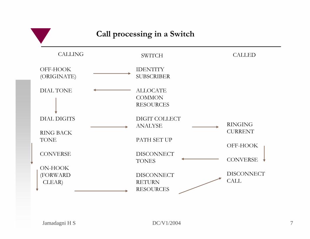
CALLING SWITCH CALLED
OFF-HOOK (ORIGINATE)
DIAL TONE
DIAL DIGITS
RING BACK TONE
CONVERSE
ON-HOOK(FORWARDCLEAR)
IDENTITYSUBSCRIBER
ALLOCATECOMMONRESOURCES
DIGIT COLLECTANALYSE
PATH SET UP
DISCONNECT TONES
DISCONNECTRETURNRESOURCES
RINGINGCURRENT
OFF-HOOK
CONVERSE
DISCONNECTCALL
Call processing in a Switch
Jamadagni H S DC/V1/2004 8
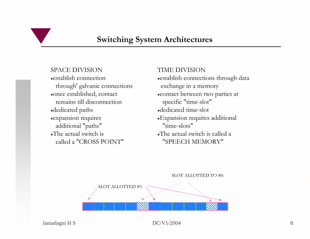
SPACE DIVISIONestablish connectionthrough' galvanic connections
once established, contactremains till disconnection
dedicated paths expansion requiresadditional "paths"
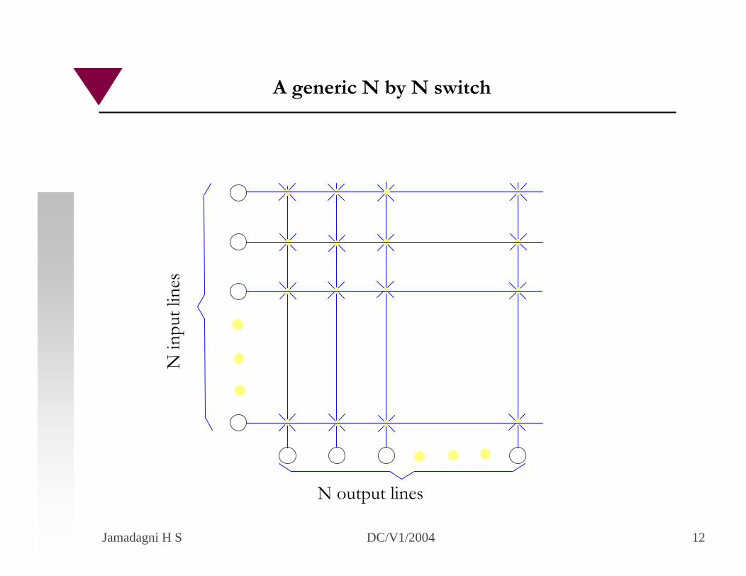
The actual switch iscalled a "CROSS POINT"
TIME DIVISIONestablish connections through dataexchange in a memorycontact between two parties atspecific "time-slot"
dedicated time-slotExpansion requires additional"time-slots"
The actual switch is called a "SPEECH MEMORY"
SLOT ALLOTTED #1
SLOT ALLOTTED TO #6
Switching System Architectures
Jamadagni H S DC/V1/2004 9
Path establishment - using extensive signallingInformation interchange - using error free communicationFacilities - offering extensive facilities to subscribersTariff computation - using extensive signallingTearing down the path after information exchange is complete -using signallingBilling - using computation facilitiesMaintenance - using computation facilities and a few added equipmentPerformance measurement - using computation facilities and a few added equipment
Switching System Operations
Jamadagni H S DC/V1/2004 10
COMMON CONTROLCONTROL through' COMPUTER HW + SWBOTH TIME DIVISION & SPACE DIVISION POSSIBLE
SPACE DIVISION SWITCHING
USING REED CONTACTS FOR CROSS POINTSUSING SOLID STATE (JFETS/MOS FETs) FOR CROSS POINTSUSING THYRISTORS/TRIACS FOR CROSS POINTS
Electronic Stored Program Control Switches
Jamadagni H S DC/V1/2004 11
Low cost for small switches (say up to 64 subscribers)Low distortion due to direct speech switchingIntroducing tones very easyCost vs service trade-off possibleFairly good bandwidthBlocking switch, particularly for large number of subscribersCost increases with number of switchesExpansion is difficultHandling data difficultLower reliability due to switches
Analogue Switch Features
Jamadagni H S DC/V1/2004 12
N in
put l
ines
N output lines
A generic N by N switch
Jamadagni H S DC/V1/2004 13
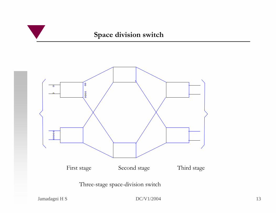
First stage Second stage Third stage
Three-stage space-division switch
Space division switch
Jamadagni H S DC/V1/2004 14
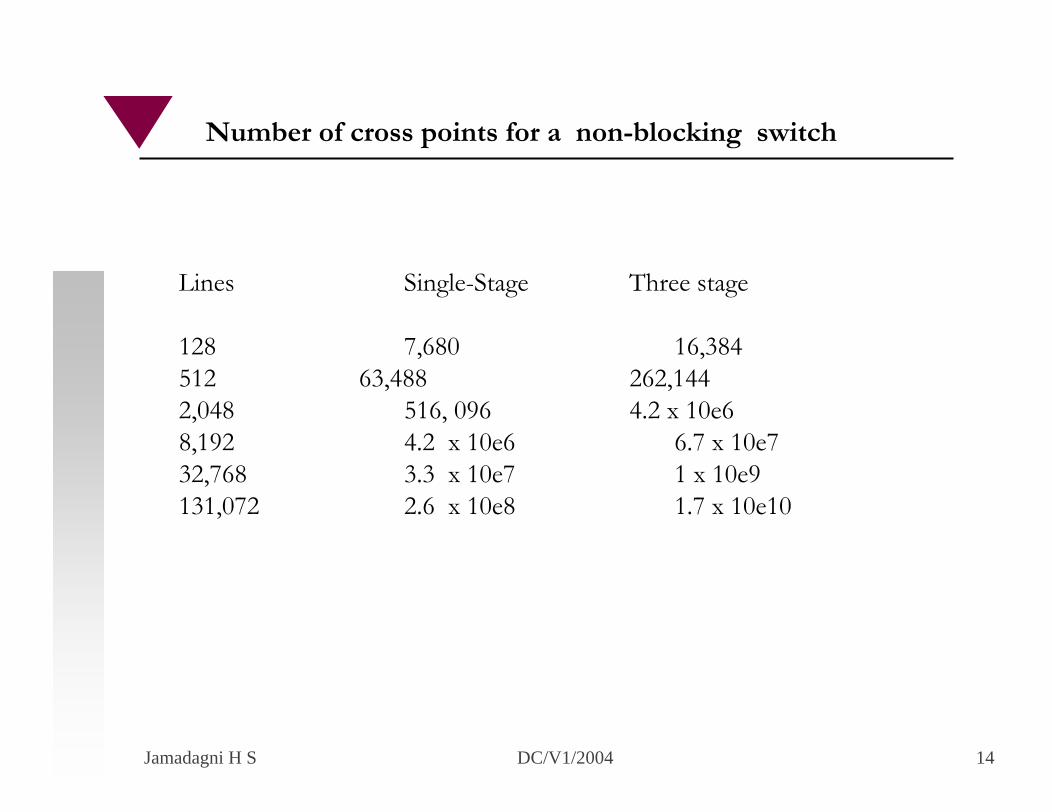
Lines Single-Stage Three stage
128 7,680 16,384512 63,488 262,144 2,048 516, 096 4.2 x 10e68,192 4.2 x 10e6 6.7 x 10e732,768 3.3 x 10e7 1 x 10e9131,072 2.6 x 10e8 1.7 x 10e10
Number of cross points for a non-blocking switch
Jamadagni H S DC/V1/2004 15
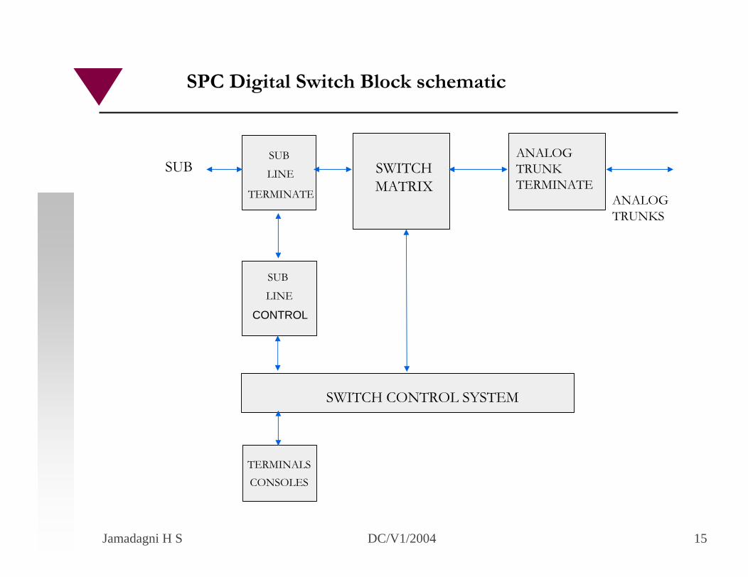
SUB
LINE
TERMINATE
SUB
LINE
SWITCHMATRIX
ANALOGTRUNKTERMINATE
CONTROL
SWITCH CONTROL SYSTEM
TERMINALSCONSOLES
SUB
SPC Digital Switch Block schematic
ANALOGTRUNKS
Jamadagni H S DC/V1/2004 16
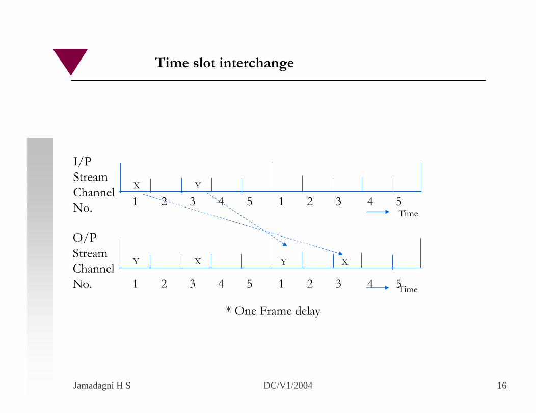
Y X
O/PStreamChannelNo.
* One Frame delay
X
Time1 2 3 4 5 1 2 3 4 5
Time
X Y
I/PStreamChannelNo.
Y
Time slot interchange
1 2 3 4 5 1 2 3 4 5
Jamadagni H S DC/V1/2004 17
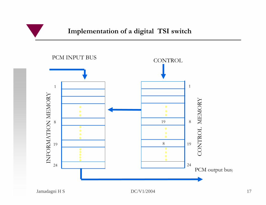
1
8
19
24
1
8
19
24
19
8
PCM INPUT BUSIN
FORM
ATI
ON
ME
MO
RY
CON
TRO
L M
EM
ORY
CONTROL
PCM output bus)
Implementation of a digital TSI switch
Jamadagni H S DC/V1/2004 18
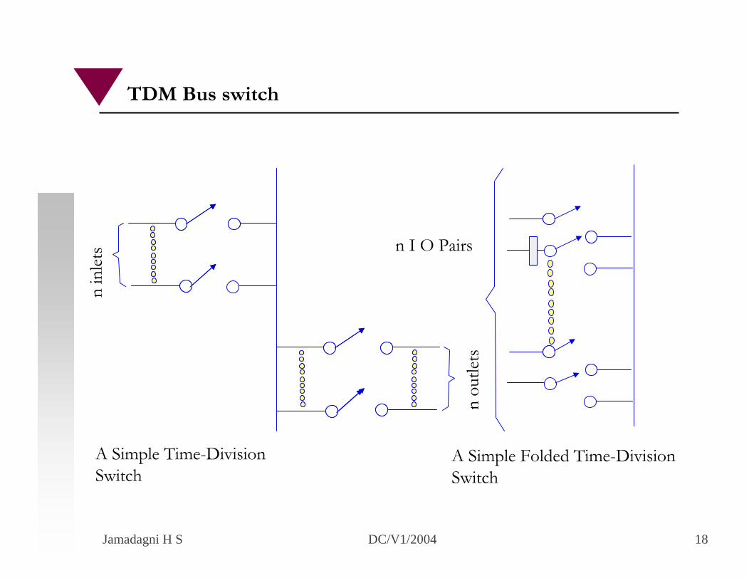
n in
lets
n ou
tlets
n I O Pairs
A Simple Folded Time-Division Switch
A Simple Time-Division Switch
TDM Bus switch
Jamadagni H S DC/V1/2004 19
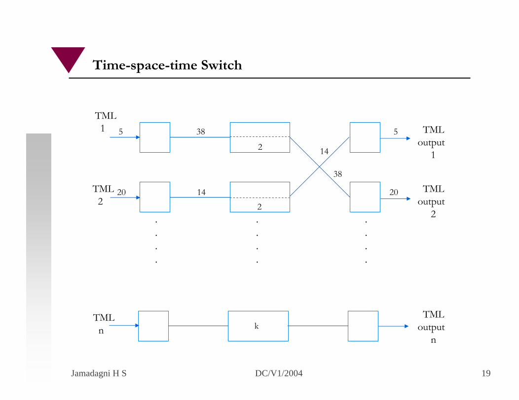
TML1
TML2
5 38 5
20 14 20
2
2
TMLoutput
1
TMLoutput
2
14
38
.
.
.
.
.
.
.
.
.
.
.
.
TMLn
TMLoutput
nk
Time-space-time Switch
Jamadagni H S DC/V1/2004 20
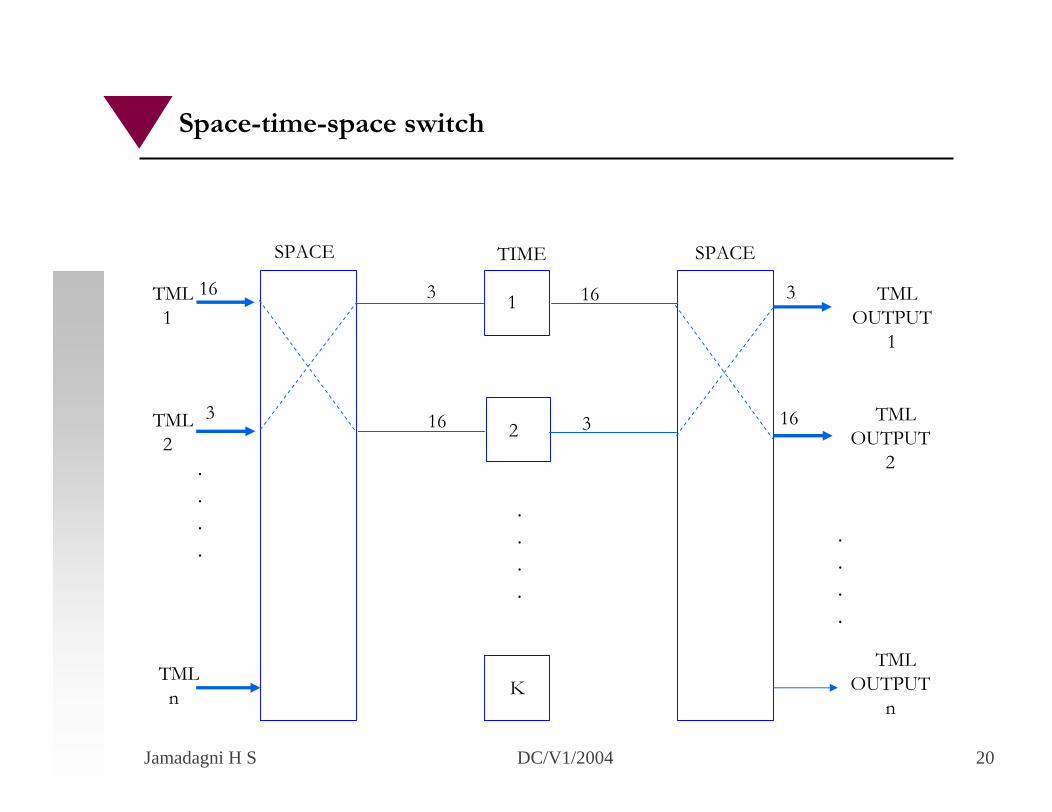
.
.
.
.
.
.
.
.
.
.
.
.
SPACE TIME SPACE
2
TML1
1 3 16
16 3
K
TML2
TMLn
TMLOUTPUT
1
3
16 TMLOUTPUT
2
TMLOUTPUT
n
16
3
Space-time-space switch
Jamadagni H S DC/V1/2004 1
Overview
• Copper Access• Bandwidth Requirements• Distance vs. Rate• ADSL• Modulation Techniques• Competing Technologies
Jamadagni H S DC/V1/2004 2
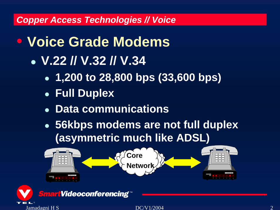
Copper Access Technologies // Voice
• Voice Grade ModemsV.22 // V.32 // V.34
1,200 to 28,800 bps (33,600 bps)Full DuplexData communications56kbps modems are not full duplex (asymmetric much like ADSL)
CoreNetwork
Jamadagni H S DC/V1/2004 3
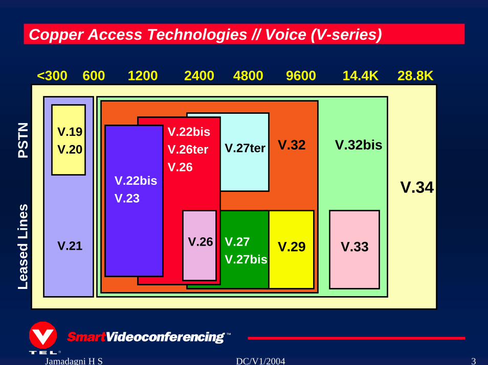
Copper Access Technologies // Voice (V-series)
<300 600 1200 2400 4800 9600 14.4K 28.8K
V.34
V.32bis
V.33
V.32
V.29
V.27ter
V.27V.27bis
V.22bisV.26terV.26
V.26
V.22bisV.23
V.21
V.19V.20PS
TNLe
ased
Lin
es
Jamadagni H S DC/V1/2004 4
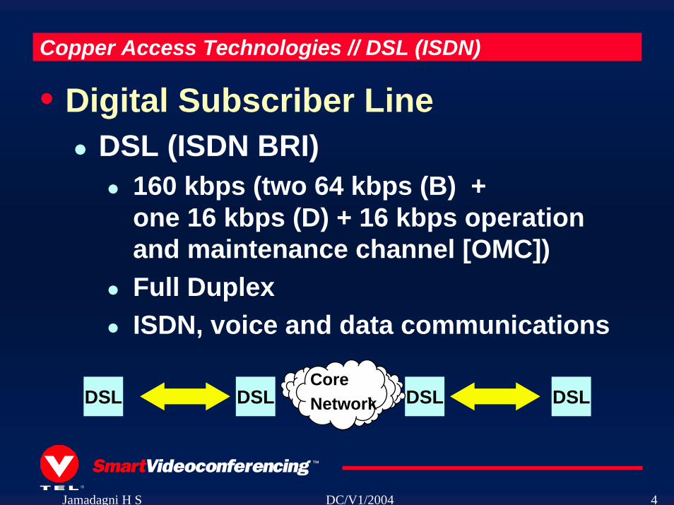
Copper Access Technologies // DSL (ISDN)
• Digital Subscriber LineDSL (ISDN BRI)
160 kbps (two 64 kbps (B) + one 16 kbps (D) + 16 kbps operation and maintenance channel [OMC])Full DuplexISDN, voice and data communications
DSL DSLCoreNetworkDSL DSL
Jamadagni H S DC/V1/2004 5
Copper Access Technologies // HDSL and SDSL
• High Data Rate and Single Line (Symmetric)
HDSL and SDSL1.544 Mbps // 2.048 MbpsFull DuplexT1/E1, telco feeders, WANSDSL (single twisted pair)
Jamadagni H S DC/V1/2004 6
Copper Access Technologies // ADSL and RADSL
• Asymmetric Digital Subscriber Line (Rate Adaptive)
ADSL // RADSL1.5 Mbps to 9 Mbps (downstream)16 kbps to 1.5 Mbps (upstream)Internet access, video on demand, remote LAN access, multimediaRADSL = adapt speeds based on conditions and distances
Jamadagni H S DC/V1/2004 7
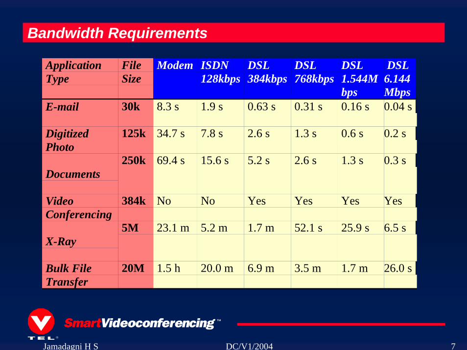
Bandwidth Requirements
ApplicationType
FileSize
Modem ISDN128kbps
DSL384kbps
DSL768kbps
DSL1.544Mbps
DSL6.144Mbps
E-mail 30k 8.3 s 1.9 s 0.63 s 0.31 s 0.16 s 0.04 s
DigitizedPhoto
125k 34.7 s 7.8 s 2.6 s 1.3 s 0.6 s 0.2 s
Documents250k 69.4 s 15.6 s 5.2 s 2.6 s 1.3 s 0.3 s
VideoConferencing
384k No No Yes Yes Yes Yes
X-Ray5M 23.1 m 5.2 m 1.7 m 52.1 s 25.9 s 6.5 s
Bulk FileTransfer
20M 1.5 h 20.0 m 6.9 m 3.5 m 1.7 m 26.0 s
Jamadagni H S DC/V1/2004 8
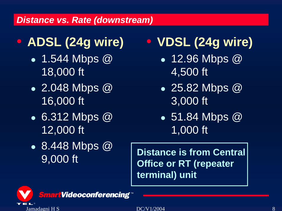
Distance vs. Rate (downstream)
• VDSL (24g wire)12.96 Mbps @ 4,500 ft25.82 Mbps @ 3,000 ft51.84 Mbps @ 1,000 ft
• ADSL (24g wire)1.544 Mbps @ 18,000 ft2.048 Mbps @ 16,000 ft6.312 Mbps @ 12,000 ft8.448 Mbps @ 9,000 ft Distance is from Central
Office or RT (repeater terminal) unit
Jamadagni H S DC/V1/2004 9
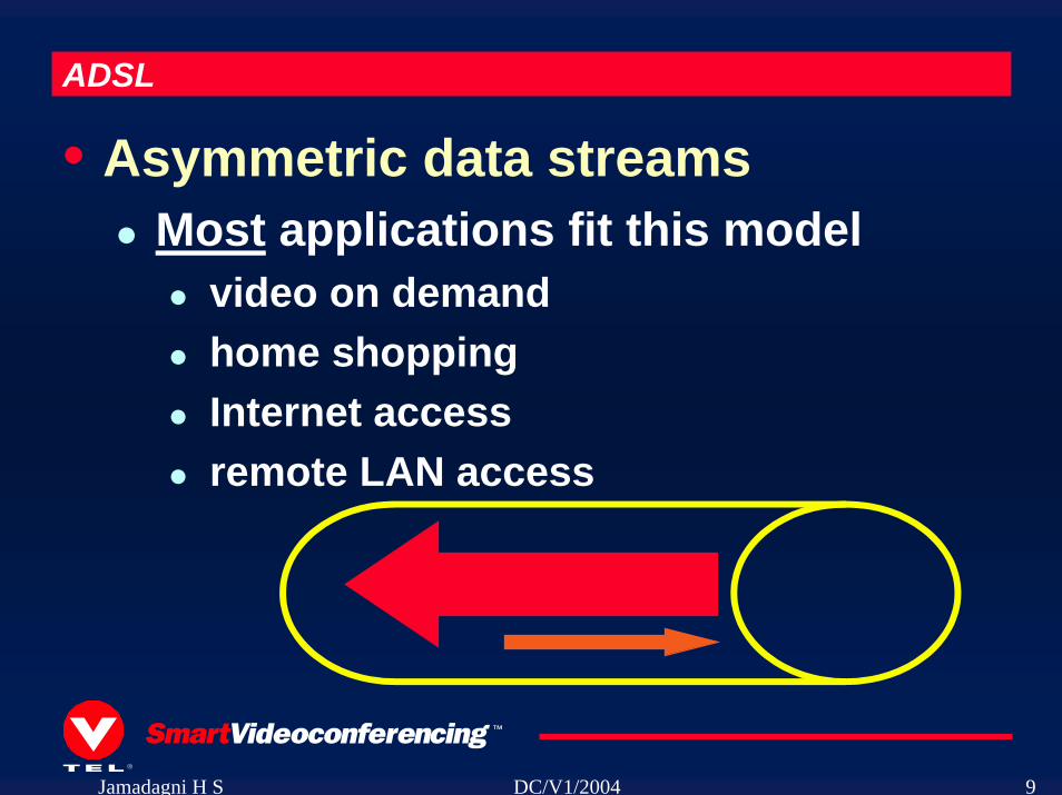
ADSL
• Asymmetric data streamsMost applications fit this model
video on demandhome shoppingInternet accessremote LAN access

Jamadagni H S DC/V1/2004 10
Jamadagni H S DC/V1/2004 11
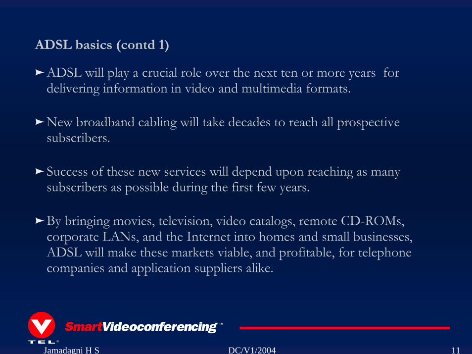
ADSL will play a crucial role over the next ten or more years for delivering information in video and multimedia formats. New broadband cabling will take decades to reach all prospective subscribers.
Success of these new services will depend upon reaching as many subscribers as possible during the first few years.
By bringing movies, television, video catalogs, remote CD-ROMs, corporate LANs, and the Internet into homes and small businesses, ADSL will make these markets viable, and profitable, for telephone companies and application suppliers alike.
ADSL basics (contd 1)
Jamadagni H S DC/V1/2004 12
ADSL basics (contd 2)
Three information channels
a high speed downstream channelSpeed ranges from 1.5 to 6.1 Mbps
a medium speed duplex channelSpeed range from 16 to 640 kbps
a POTS (Plain Old Telephone Service) or an ISDN channel. The POTS/ISDN channel is split off from the digital modem by filters, thus guaranteeing uninterrupted POTS/ISDN, even if ADSL fails.
Each channel can be submultiplexed to form multiple, lower rate channels, depending on the system.Consistent with North American and European digital hierarchies
Jamadagni H S DC/V1/2004 13
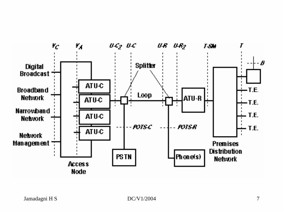
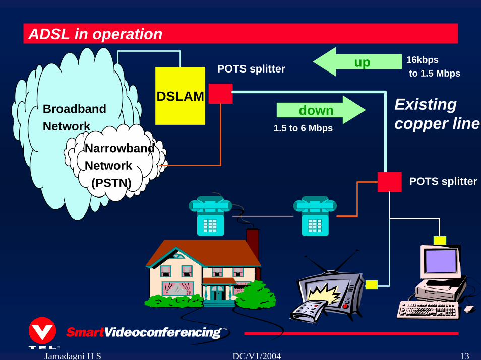
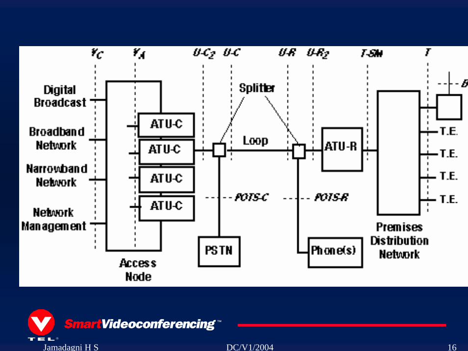
ADSL in operation
BroadbandNetwork
NarrowbandNetwork(PSTN)
DSLAM
POTS splitter
POTS splitter
Existing copper line
down1.5 to 6 Mbps
up 16kbpsto 1.5 Mbps
Jamadagni H S DC/V1/2004 14
Jamadagni H S DC/V1/2004 15
ADSL reach
Data Rate Distance Wire Size Distance
1.5 or 2 Mbps 18,000 ft 0.5 mm 5.5 km 1.5 or 2 Mbps 15,000 ft 0.4 mm 4.6 km 6.1Mbps 12,000 ft 0.5 mm 3.7 km 6.1 Mbps 9,000 ft 0.4 mm 2.7 km
Jamadagni H S DC/V1/2004 16
Jamadagni H S DC/V1/2004 17
Jamadagni H S DC/V1/2004 18
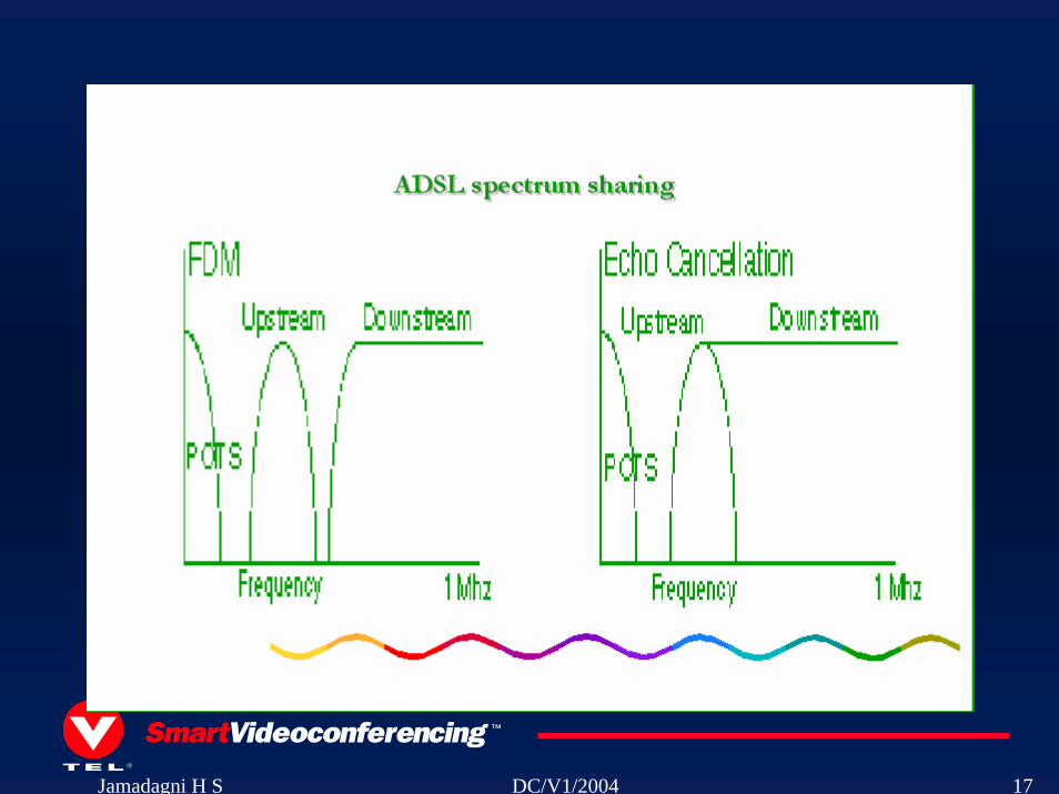
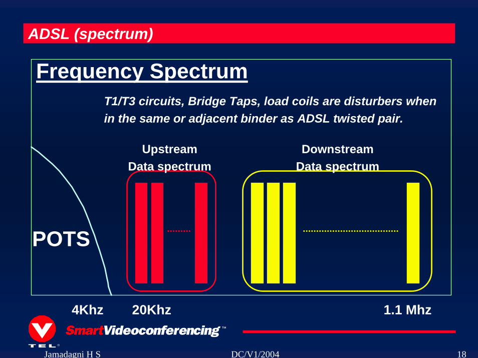
ADSL (spectrum)
UpstreamData spectrum
DownstreamData spectrum
POTS
20Khz 1.1 Mhz4Khz
Frequency SpectrumT1/T3 circuits, Bridge Taps, load coils are disturbers whenin the same or adjacent binder as ADSL twisted pair.
Jamadagni H S DC/V1/2004 19
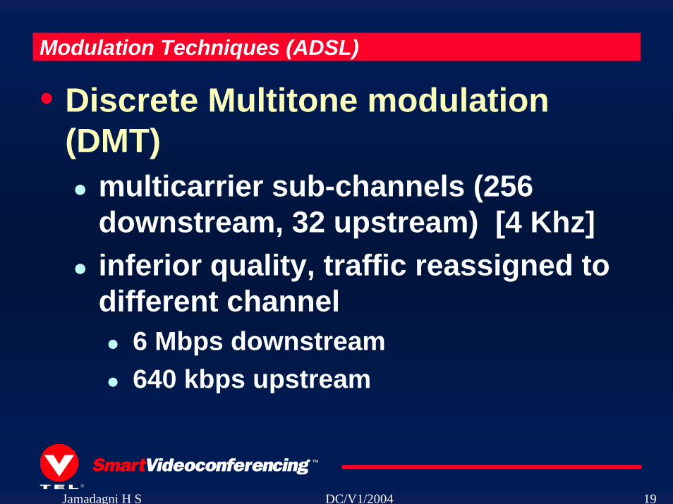
Modulation Techniques (ADSL)
• Discrete Multitone modulation (DMT)
multicarrier sub-channels (256 downstream, 32 upstream) [4 Khz]inferior quality, traffic reassigned to different channel
6 Mbps downstream640 kbps upstream
Jamadagni H S DC/V1/2004 20
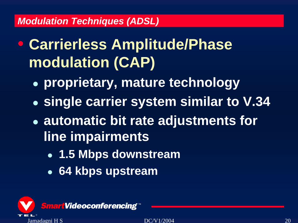
Modulation Techniques (ADSL)
• Carrierless Amplitude/Phase modulation (CAP)
proprietary, mature technologysingle carrier system similar to V.34automatic bit rate adjustments for line impairments
1.5 Mbps downstream64 kbps upstream
Jamadagni H S DC/V1/2004 21
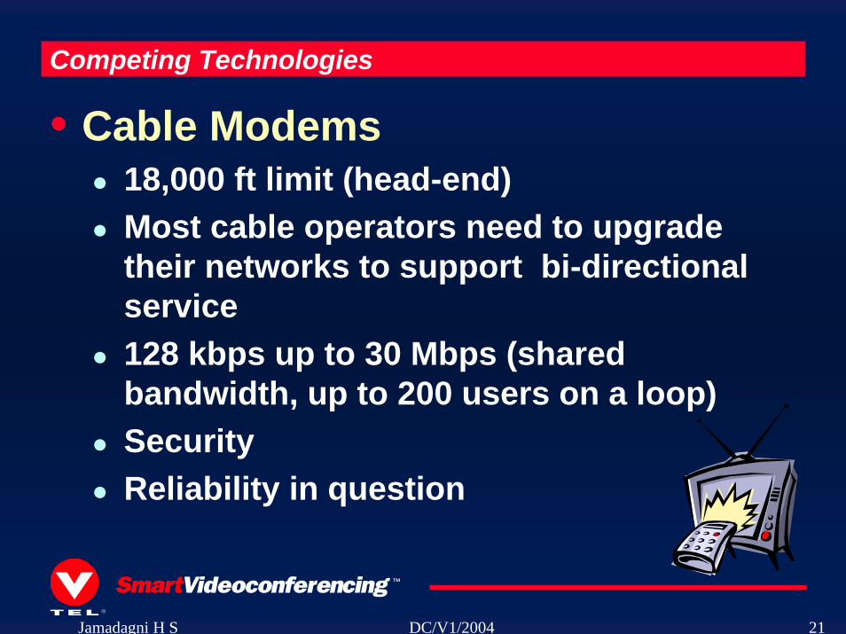
Competing Technologies
• Cable Modems18,000 ft limit (head-end)Most cable operators need to upgrade their networks to support bi-directional service 128 kbps up to 30 Mbps (shared bandwidth, up to 200 users on a loop)SecurityReliability in question
Jamadagni H S DC/V1/2004 22
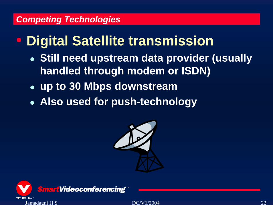
Competing Technologies
• Digital Satellite transmissionStill need upstream data provider (usually handled through modem or ISDN)up to 30 Mbps downstreamAlso used for push-technology
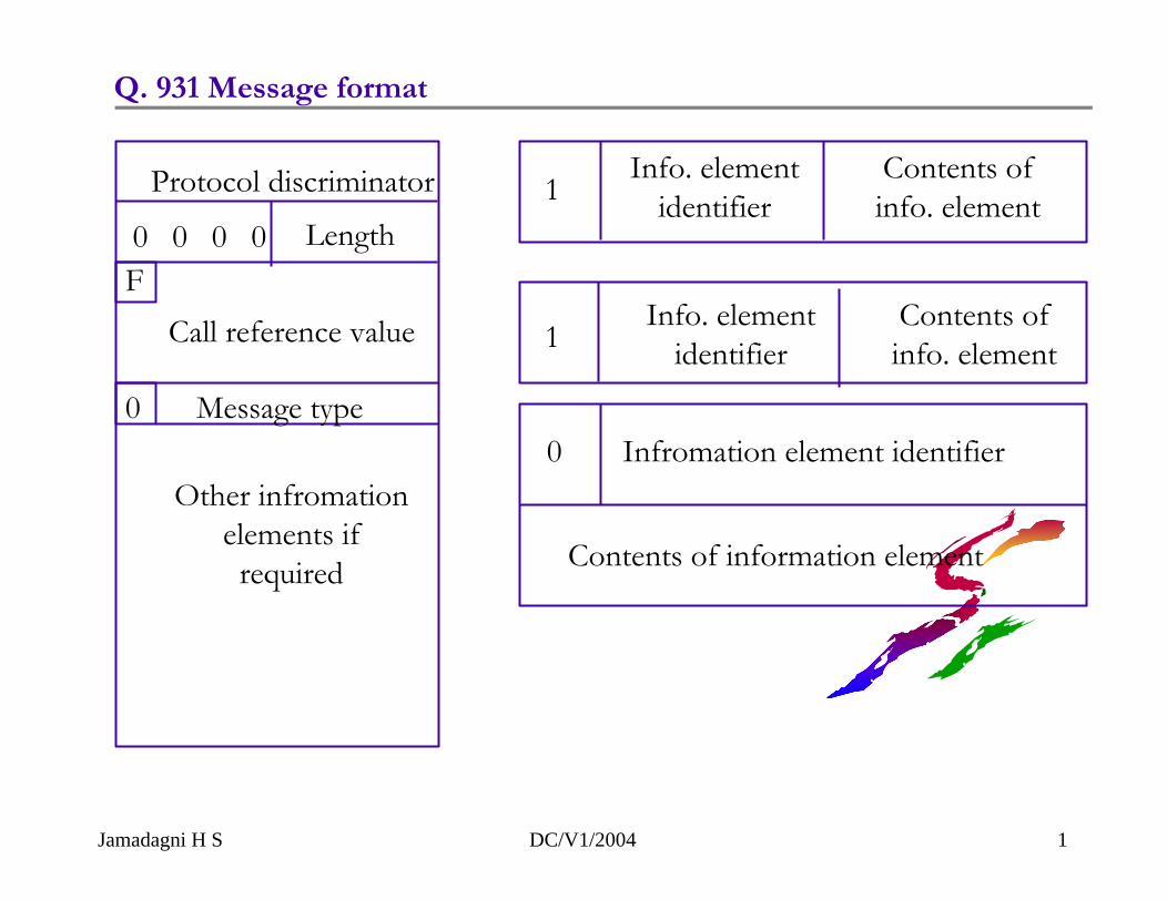
Protocol discriminator
0 0 0 0 Length
Call reference valueF
0 Message type
Other infromationelements if
required
Q. 931 Message format
1Info. element
identifierContents ofinfo. element
1Info. element
identifierContents ofinfo. element
0 Infromation element identifier
Contents of information element
Jamadagni H S DC/V1/2004 1
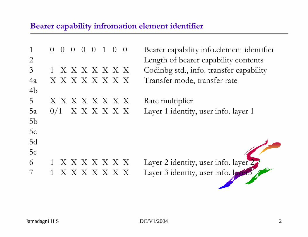
Bearer capability infromation element identifier
1 0 0 0 0 0 1 0 0 Bearer capability info.element identifier2 Length of bearer capability contents3 1 X X X X X X X Codinbg std., info. transfer capability4a X X X X X X X X Transfer mode, transfer rate4b5 X X X X X X X X Rate multiplier5a 0/1 X X X X X X Layer 1 identity, user info. layer 15b5c5d5e6 1 X X X X X X X Layer 2 identity, user info. layer 27 1 X X X X X X X Layer 3 identity, user info. layer3
Jamadagni H S DC/V1/2004 2
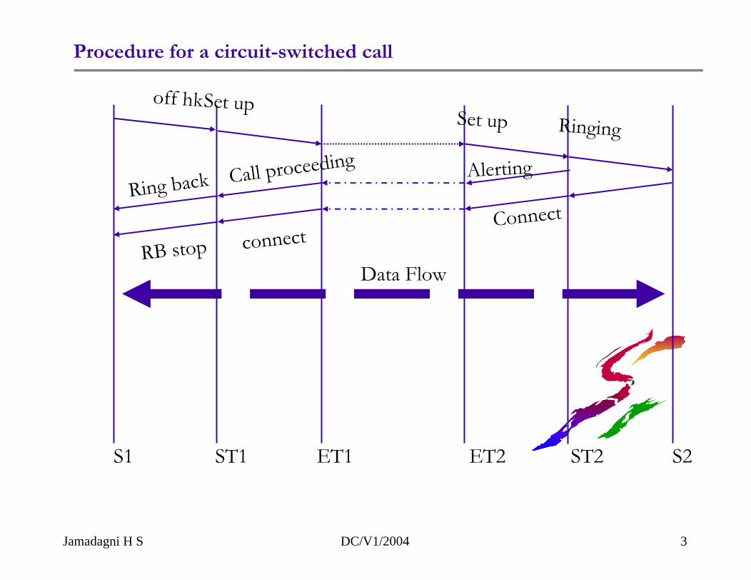
Procedure for a circuit-switched call
Data Flow
off hkSet upSet up Ringing
Ring back Call proceeding Alerting
RB stop connectConnect
S1 ST1 ET1 ET2 ST2 S2
Jamadagni H S DC/V1/2004 3
Terminal CallProcessing
Basic ServiceProtocol(Q.931)
SupplementaryServicesProtocol(Facility)
Q.931 Messages
LAPD
1.430/1.431
Exchange Call Processing
Basic ServiceProtocol(Q.931)
SupplementaryServicesProtocol(Facility)
Q.931 Messages
LAPD
1.430/1.431
Modelling of basic and supplementary services
Jamadagni H S DC/V1/2004 1
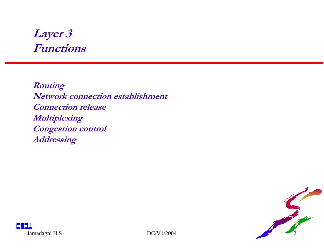
Layer 3 Functions
Jamadagni H S DC/V1/2004 2
RoutingNetwork connection establishmentConnection releaseMultiplexingCongestion controlAddressing
Layer 2 Functions
Jamadagni H S DC/V1/2004 3
Traffic over D channel (control Info and data over D) Q 921
Q921 services
Convey user Info between layers entities using D channelSupport multiple terminals at user-NW installationMultiple layer 3 entity: support two types of transferUnacknowledged transfer (unnumbered frames)Acknowledged transfer (like X 25) HDLC
Function of other layers
Jamadagni H S DC/V1/2004 4
layer 4 : error detection / recoveryflow controllayer 4 connection, release, muxing
Layer 5 : session connectionmanagementsession - transport management
layer 6 : encryption / decryptioncompression / expansion
Layer 7 : application related functions
Jamadagni H S DC/V1/2004 5
1. Protocol reference model I320
Circuit - switched connection under common channel signallingPacket - switched comm over B/D/HSignalling between users and network based facilities (data base fores.)End - to - end signalling for users Combinations for multimedia comm.
2. Types of Info flow
1. User Info: digitised voice, data between users. Transmitted transparently through ISDNor processed (encrypted for e.g.)
2. Control Info : acted upon this Info switching a connection / clearing change service characteristics
Protocol reference model I 320
Basic Call Control
Jamadagni H S DC/V1/2004 6
interact with layer 2 (LAPD) to transmit / receive messagesgenerate and interpret layer 3 messagesadmin of times and logical entities (call reference) used in controladmin of resources (like B ch1)check to provide proper service consistent with user requirementsrouting / relayingnetwork connection controlerror detection (sequences)error recoverysequencing layer 3 information
Layer 1 Functions
Jamadagni H S DC/V1/2004 7
Encoding of digital data for transmission across the interfaceFull-duplex transmission of B channel dataFull-duplex transmission of D channel data.Multiplexing of channels to form basic or primary access transmission
structure.Activation and deactivation of physical circuit.Power feeding from network termination to the terminal.Terminal identification.Faulty terminal isolation.D channel contention access
Jamadagni H S DC/V1/2004 8
Circuit - mode connection control functions needed for circuit-switched B channel calls
Packed - mode connection control functions needed for circuit-switched connections to ISDN packet-switched node.
User - user signalling messages with global call reference
functions are 4 types
call establishment set up a call on B chl.call information user-NW Info transfer after set-upcall clearingmiscellaneous
Q931 message types
Jamadagni H S DC/V1/2004 9
Signaling exchanged between user - network, network - network.
Protocol discriminator (0001000) for Q931 call referenceMessage type: length (1 for BRI, 2 for PRI)Call reference: call reference value (assigned by TE local significance)Flag: 0: originator, 1: remote endCall reference length = 0, Supplementary services Q932CRF = 0, global CRF
Messages
Q931 messages for circuit mode connections
Jamadagni H S DC/V1/2004 10
Call Establishment Messages
Message Significance Direction Function
ALERTING global both Indicates that user alerting has begunCALL PROCEEDING local both Indicates that call establishment has
been initiatedCONNECT global both Indicates call acceptance by called TECONNECT local both Indicates that user has been ACKNOWLEDGE awarded the callPROGRESS global both Reports progress of a callSETUP global both Initiates call establishmentSETUP local both Indicates that call establishmentACKNOWLEDGE has been initiated but requests
more information
Jamadagni H S DC/V1/2004 11
Message Significance Direction Function
RESUME local u n Requests resumption of previously suspended call
RESUME local n u Indicates requested call has ACKNOWLEDGE been reestablishedRESUME REJECT local n u Indicates failure to resume suspended
callSUSPEND local u n Requests suspension of a call SUSPEND local n u Indicates call has been suspendedACKNOWLEDGESUSPEND REJECT local n u Indicates failure of requested call
suspension
Call information phase messages
Jamadagni H S DC/V1/2004 12
Message Significance Direction Function
DISCONNECT global both Sent by user to request connectionclearing; sent by network to indicateconnection clearing
RELEASE local both Indicates intent to release channel andcall reference
RELEASE local both Indicates release of channel and callCOMPLETE referenceINFORMATION local both Provides additional informationNOTIFY both Indicates information pertaining to a callSTATUS local both Sent in response to a STATUS
INQUIRY or at any time to report an errorSTATUS local both Solicits STATUS messageINQUIRY
Call clearing messages
Jamadagni H S DC/V1/2004 13
FLAG ADDRESS CONTROL INFORMATION FCS FLAG
8 bits 16 8 or 16 Variable 16 8
(a) Frame format
0 C/R SAPI 1 TEI
C/R is Command/responseSAPI is Service access point identifierTEI is Terminal endpoint identifier
Frame format in ISDN layer 2
Jamadagni H S DC/V1/2004 14
0 N(S) P/F N(R)
1 0 SS0 0 0 0 P/F N(R)
1 1 M M P/F M M M
Informationtransfer
Supervisory
Unnumbered
N(S) = Transmitter send sequence numberN(R) = Transmitter receive sequence numberS = Supervisory function bitM = Modifier function bitP/F = Poll/final bit
LAPD format
Jamadagni H S DC/V1/2004 15
Name Control Field C/R Description
Information format
I (Information) 0-N(S)--P-N(R)-- C Exchange user data
Supervisory Format
RR (Receive Ready) 10000000*-N(R)-- C/R Positive ack; ready to receive I-frame
RNR (Receive Not 10100000*-N(R)-- C/R Positive ack; not ready topReady) receiveREJ (Reject) 10010000*-N(R)-- C/R Negative ack; go back N
LAPD commands and responses
Unnumbered format
Jamadagni H S DC/V1/2004 16
SABME (Set Asyn 1111P110 C Request logical connectionchronous BalancedMode)DM (Disconnected 1111F000 R Unable to establish or mainMode) maintain logical connectionUI (unnumbered 1100P000 C Used for unacknowledgedInformation) information transfer serviceDISC (Disconnect) 1100P010 C Terminate logical connectionUA (Unnumbered 1100F110 R Acknowledge SABME or DISCAcknowledgement)FRMR (Frame Reject) 1110F001 R Reports receipt of unaccept-
able frameXID (Exchange ID- 1111*101 C/R Exchange identification informationidentification)
Jamadagni H S DC/V1/2004 17
(a) SAPI AssignmentsSAPI Value Related Protocol or Management Entity
0 Call-control procedures16 packet communication conforming to X.25 level 332-61 Frame relay communication63 Layer 2 management proceduresAll others Reserved for future standardisation
(b) TEI AssignmentsTEI Value User Type
0-63 Nonautomatic TEI assignment userequipment
64-126 Automatic TEI assignment user equipment127 Used during automatic TEI assignment
SAPI and TEI assignments
Jamadagni H S DC/V1/2004 18
* ** * * ** * ** * * *
SAPI = 0 SAPI = 16
SAP identifierDatalinklayer
SI: Signalling informationPD: Packet data
Data linklayer
Data linklayer
TEI = 127
TEI = 5
TEI = 127
TEI = 5
B B1B1 1 2 3 2 1 B 1 B
UserET/NT2
Connection endpoint suffixCustomer premises
Network
Layer 3TE(2) TE(1)
0 1616 0 0
PDPD SI SI SI
TEI = 3, 8, 127
TEI and SAPI assignment
Jamadagni H S DC/V1/2004 19
NRZ-L
Bipolar-AMI
Pseudo-ternary
0 1 0 0 1 1 0 0 0 1 1
Digital Signal Encoding Format in ISDN
Jamadagni H S DC/V1/2004 20
Contact Assignments for Plugs and Jacks of ISDN
ContactNumber TE NTa Power Source 3 Power Sink 3b Power Source 3 Power Sink 3c Transmit Received Received Transmite Received Transmitf Transmit Receivedg Power Sink 2 Power Source 2h Power Sink 2 Power Source 2
Physical connector in ISDN
Jamadagni H S DC/V1/2004 21
Fixed by local administration
4 wire interface no echo cancellation procedures, simple line termination
2 wire interfacePing-Pong operation, no echo cancellation, only one cable pair,
simple termination, limited lengths, extra processing for comm. direction handling
2 wire interfacefull duplex operation, echo cancellation, only one cable pair, no
limitation on length , extensive processing for echo cancellation
The U interface
Jamadagni H S DC/V1/2004 22
+RX Data DecisionFeedback
Equalisation
LineEncoding
EchoCancellor Hybrid DSL
TX Data
Σ AD
U interface circuit
Jamadagni H S DC/V1/2004 23
ISWSWSWSWSWSWSWSW
12345678
2B + D2B + D2B + D2B + D2B + D2B + D2B + D2B + D
2B + D2B + D2B + D2B + D2B + D2B + D2B + D2B + D
2B + D2B + D2B + D2B + D2B + D2B + D2B + D2B + D
18 18 18 18 6 total 240 bits
M1 to M6M1 to M6M1 to M6M1 to M6M1 to M6M1 to M6M1 to M6M1 to M6
SW = Sync Word = +3+3-3-3-3+3-3+3+3ISW= Inverted SW=-3-3+3+3+3-3+3-3-32B+D = |B1 |B2 |D | (|8|8|2) M1 to M6 over head bitsData are encoded as 00 = -3, 01= -1, 11=+1, 10 = +3
ANSI U interface frame and superframe structure