diffusion bonding aluminium alloys and composites · pdf filediffusion bonding aluminium...
TRANSCRIPT
Diffusion Bonding Aluminium Alloys and Composites: New Approaches and Modelling
Amir A. Shirzadi
King’s College Cambridge
A thesis submitted for the degree of
Doctor of Philosophy at the University of Cambridge
December 1997
Declaration
This thesis describes work undertaken in the Department of Materials Science and
Metallurgy at the University of Cambridge between April 1994 and December 1997.
The work is entirely my own and includes nothing which is the outcome of work done
in collaboration, except where reference is explicitly made to the work of others. The
work has not been submitted, either in whole or in part, for any degree or qualification
at any other university and does not exceed 60,000 words.
This work was financially supported by the Ministry of Higher Education of Iran, the
Committee of Vice-Chancellors and Principals of the Universities of the United
Kingdom (ORS Award Scheme), and King’s College, the University of Cambridge.
Amir A. Shirzadi Cambridge December 1997
Acknowledgement
I am wholeheartedly grateful to my supervisor, Dr Rob Wallach, for his guidance,
encouragement and invaluable friendship during my research period in Cambridge. It is
a pleasure for me to acknowledge Dr Sue Jackson for her advice and ever friendly
support. Also, I would like to thank Dr Ian Bucklow for the useful discussions I had
with him on my work.
I sincerely thank Dr Hamid Assadi for his advice and help throughout my research, and
also Fataneh who provided an enjoyable atmosphere for Hamid and me to carry on with
our discussions. I am also grateful to Mohammed Balamdi for “tidying” my room
frequently and Kaveh Chamandar who kept correcting my English accent so patiently.
Thanks are also due to my friends at King’s College: Clea for her kind friendship and
food-wise logistic; Liz, Ken, Kai and Paul for improving my knowledge to the single
currency issue during our outings.
I am grateful to Professor Alan Windle, the Head of the Department, for providing
laboratory facilities, and I express my gratitude to my research colleagues, academic
and technical staff in the Department who helped me so sincerely in the course of my
research. Finally, thanks to the staff in my college for their help and many others who
made my time in Cambridge so enjoyable.
A.A. Shirzadi University of Cambridge Ph.D. Thesis
i
Abstract
Development of a suitable joining technique for advanced aluminium alloys and
composites will enable them to be more widely used. The aim of this Ph.D. research
was to develop new joining methods for these materials for which conventional welding
methods have been unsuccessful. The research led to six new bonding methods and also
to an analytical model which may be applicable to all transient liquid phase (TLP)
bonding processes.
In the early stage of the research, two new methods for TLP diffusion bonding of
aluminium-based composites (aluminium alloys with silicon carbide particles as
reinforcement) were developed. The methods were based on applying isostatic pressure
(rather than conventional uniaxial compression), and bonds were fabricated with shear
strengths as high as 242 MPa which is 92% of the shear strength of the parent material.
This value is far greater than the highest bond strength reported to date for these
aluminium-based composites.
Based on simple finite element analysis modelling, a third method was developed which
allows the joining of superplastic alloys/composites with minimal deformation. This
method is based on a combination of conventional TLP diffusion bonding and hot
isostatic pressing without encapsulation. It allows the fabrication of intricate parts with
virtually no deformation during the bonding process so that dimensional tolerances are
preserved.
A fourth method, which is based on a new approach to TLP diffusion bonding by
introducing a temperature gradient, is capable of producing reliable bonds with shear
strengths as high as those of the parent alloys. The use of this method led to the
formation of non-planar interfaces, compared to planar interfaces associated with
A.A. Shirzadi University of Cambridge Ph.D. Thesis
ii
conventional diffusion bonding methods. Therefore the strength and reliability of the
bonds, made using this method, were improved considerably. This fourth method has
already been patented in the United Kingdom (UK 9709167.2).
A comprehensive analytical model was developed to predict the bonding time and the
microstructure of the bond line when using temperature gradient TLP diffusion
bonding. The model has been experimentally verified. The model also may be
applicable to all TLP diffusion bonding approaches.
The fifth method, developed in the current research, is capable of fabricating reliable
bonds in air with shear strengths as high as 90% of those of the parent material. This is
the highest bond strength, reported to date, for diffusion-bonded aluminium joints made
in air. The approach overcomes the limitations associated with bonding aluminium-
based materials in vacuum; this has been a major restriction in exploitation of the
process. Patent protection has been sought (UK 9811860.7).
Based on a combination of the fourth and fifth methods, a sixth method is proposed to
improve the reliability of bonds made in air (temperature gradient TLP diffusion
bonding in air). Preliminary results are very promising and some suggestions for further
work on this method are proposed.
A.A. Shirzadi University of Cambridge Ph.D. Thesis
iii
Table of Contents
1. Introduction..........................................................................................1 Summary of the work in this dissertation ..........................................................................2
2. Literature survey..................................................................................4
2.1 Theoretical aspects of solid-state diffusion bonding .......................7
2.2 Theoretical aspects of transient liquid phase (TLP) diffusion bonding ........................................................................10
Modelling of TLP diffusion bonding................................................................................12
Modelling of TLP diffusion bonding of composites ........................................................16
2.3 Solid-state diffusion bonding of aluminium alloys .......................18 Imposing macroscopic plastic deformation ....................................................................18
Enhancing microplastic deformation of the surface asperities .....................................18
Use of interlayers and the effect of alloying elements ....................................................20
Non-conventional bonding and testing methods.............................................................21
2.4 TLP diffusion bonding of aluminium alloys .................................24 Zinc based interlayers ......................................................................................................24
Silver interlayers ...............................................................................................................25
Copper interlayers ............................................................................................................25
2.5 Joining aluminium metal matrix composites ................................27
2.6 Diffusion bonding of aluminium-based materials in air................31
2.7 Summary......................................................................................33 Appendix.....................................................................................................35
A.A. Shirzadi University of Cambridge Ph.D. Thesis
iv
3. Experimental procedure ....................................................................37
3.1 Parent materials and interlayers....................................................37
3.2 Bond fabrication...........................................................................39 3.2.1 Pre-bonding procedure.......................................................................39 3.2.2 Bonding procedure.............................................................................40
Method I: Isostatic TLP diffusion bonding....................................................................42
Method II: Low pressure conventional TLP diffusion bonding followed by isostatic solid-state diffusion bonding in air .........................................42
Method III: Low pressure conventional TLP diffusion bonding followed by hot isostatic pressing (HIP) without encapsulation ..............................44
Method IV: Temperature gradient TLP diffusion bonding ..........................................44
Method V: High heating rate TLP diffusion bonding in air .........................................44
Method VI: Temperature gradient TLP diffusion bonding in air ................................47
3.2.3 Post bond heat treatment ....................................................................49
3.3 Bond testing and evaluation .........................................................51 3.3.1 Mechanical testing .............................................................................51
3.3.2 Metallographic examination...............................................................52
4. Methods I, II and III: New methods for TLP diffusion bonding aluminium-based composites .............................................55
4.1 Introduction..................................................................................55
4.2 The aim of using isostatic pressure for TLP diffusion bonding of aluminium MMCs .....................................................58
4.3 Results and discussion..................................................................60 4.3.1 Methods I and II.................................................................................60 4.3.2 Bonds in Al-Li alloy (UL-40).............................................................71
4.3.3 Method III..........................................................................................73
4.4 Case study: The role of reinforcement particles when diffusion bonding Al-MMCs.......................................................77
4.5 Summary......................................................................................81
A.A. Shirzadi University of Cambridge Ph.D. Thesis
v
5. Method IV: Temperature gradient TLP diffusion bonding............83
5.1 Introduction..................................................................................83
5.2 Theoretical aspects of temperature gradient TLP diffusion bonding ........................................................................84
5.3 Numerical simulation of temperature gradient TLP diffusion bonding ........................................................................87
5.4 Results and discussion..................................................................89 5.4.1 Microstructure examination ...............................................................89 5.4.2 Shear test results ................................................................................93
5.4.3 Chemical analysis and hardness testing results ...................................97
5.5 Summary......................................................................................99 Appendix...................................................................................................100
6. Analytical modelling of temperature gradient TLP diffusion bonding (method IV).......................................................................101
6.1 Background................................................................................102
6.2 Precise analytical solution ..........................................................103
6.3 Geometrical approach: conservation of mass..............................108
6.4 Combination of analytical and mass conservation approaches....111
6.5 Experimental verification of modelling ......................................118 6.5.1 Experimental procedure and results..................................................118
6.6 Summary....................................................................................123
7. Methods V and VI: New methods for TLP diffusion bonding aluminium alloys in air ...................................................................124
7.1 Introduction................................................................................124
7.2 Method V: High heating rate TLP diffusion bonding in air .......126
A.A. Shirzadi University of Cambridge Ph.D. Thesis
vi
7.2.1 Results of method V and discussion .................................................128
7.3 Method VI: Temperature gradient TLP diffusion bonding in air ............................................................................135 7.3.1 Results of method VI and discussion................................................136
7.4 Summary....................................................................................138
8. Conclusions and proposal for future work .....................................140
8.1 Experimental results ...................................................................140 Method I...........................................................................................................................140
Method II .........................................................................................................................140
Method III........................................................................................................................141
Method IV ........................................................................................................................141
Method V .........................................................................................................................142
Method VI ........................................................................................................................142
Al-Li (UL-40) bonds .......................................................................................................143
Summary ..........................................................................................................................143
8.2 Modelling of method IV.............................................................146
8.3 Future work................................................................................147
References ..............................................................................................150
Chapter 1 Introduction
1
Chapter 1
1. Introduction
In the last three decades, the development of advanced materials with superior
mechanical properties has underpinned rapid progress in manufacturing of new
products. The ever increasing demand for high performance materials has spurred
research into the development of advanced alloys and composites. Transport industries,
particularly aerospace and more recently car manufacturers, have been interested
particularly in materials with high strength-to-weight ratios as these can provide
significant performance benefits.
Since the development of the first heat-treatable aluminium alloy in the early years of
this century, aluminium alloys have been of interest because of their high strength-to-
weight ratio, formability, corrosion resistance and long-term durability. The first all-
aluminium aeroplane was manufactured in 1920 and since then, despite significant
advances in non-metallic composites and titanium-based materials, aluminium alloys
are still the major materials for aerostructures, Staley et al. (1997). Aluminium metal
matrix composites (Al-MMCs) possess even better mechanical properties compared to
un-reinforced aluminium alloys (especially their high stiffness, strength and wear
resistance). Following the recent development of low cost manufacturing processes, Al-
MMCs with silicon carbide or alumina particle reinforcement (i.e. discontinuously
reinforced aluminium, DRA) are now available commercially. The use of Al/SiC
composites has reduced the production costs and improved the performance of aircraft
components, Materials Progress (1997).
However, despite substantial improvements in the range and properties of such
Chapter 1 Introduction
2
advanced aluminium-based materials, the lack of a reliable and economic joining
method has restricted their full potential.
Due to the high temperatures inherent in fusion welding processes, the use of these
methods for joining some of the advanced aluminium-based materials (e.g. Al-Li alloys
and Al/SiC MMCs) proved unsuccessful. Detrimental reactions are reduced when
joining using solid or liquid state diffusion bonding as these processes are carried out at
lower temperatures than fusion welding processes.
Unfortunately, the results of more than three decades of research on diffusion bonding
aluminium-based materials have not convinced design engineers that diffusion bonding
is a reliable and commercial method for joining these materials. A particular
discouraging feature when diffusion bonding aluminium-based materials is the wide
scatter in the results. Also, in most cases either the bond strengths are well below the
strength of the parent material, or the bonding process is associated with intolerable
plastic deformation which is required to achieve reasonable bond strengths. Some of the
approaches tried rely on sophisticated pre-bonding processes and equipment which
restrict considerably the application of the method.
In order to overcome the problems associated with the diffusion bonding of aluminium
based materials, six new methods for liquid-state diffusion bonding of aluminium-based
materials have been developed in the current work. An analytical model for the fourth
method is proposed and verified experimentally. This model also has the potential to
predict bonding times in other liquid-state diffusion bonding approaches.
Summary of the work in this dissertation
In Chapter 2, the basic definitions and theoretical aspects of solid and liquid state
diffusion bonding are detailed. Previous investigations on solid and liquid state
diffusion bonding of aluminium alloys have been categorised and compared by
considering the basis of the technique or the type of interlayer used. Joining methods
developed for Al-MMCs are reviewed, and the diffusion bonding of aluminium-based
materials in air is reviewed in the final section. The experimental procedures for the
Chapter 1 Introduction
3
new liquid-state diffusion bonding methods and the techniques used for bond evaluation
are described in Chapter 3.
In Chapter 4, the first three methods (methods I, II and III), developed for joining Al-
MMCs, are explained. Methods I and II are based on applying isostatic pressure (rather
than conventional uniaxial compression), and bonds were fabricated, using method II,
with shear strengths as high as 242 MPa which is 92% of the shear strength of the
parent material. Based on simple finite element analysis modelling, a third method was
developed which allows the joining of superplastic alloys/composites with minimal
deformation. This method is based on a combination of conventional TLP diffusion
bonding and hot isostatic pressing (HIP) without encapsulation. It allows the fabrication
of intricate parts with virtually no deformation during the bonding process so that
dimensional tolerances are preserved. Patent protection is being investigated for this
method (Method III).
A fourth method, which is based on a new approach to TLP diffusion bonding, is
capable of producing reliable bonds with shear strengths as high as that of the parent
material. This method is described in Chapter 5, and has been patented in the United
Kingdom (UK 9709167.2). A comprehensive analytical model, capable of predicting
the bonding time and the microstructure of the bond line, is presented in Chapter 6.
The model has been verified experimentally.
The fifth method is capable of fabricating reliable bonds in air with shear strengths as
high as 90% that of the parent material. This approach overcomes the limitations
associated with bonding aluminium-based materials in vacuum which has been a major
restriction in exploitation of the process. The method is outlined in Chapter 7. Patent
protection has been applied for. The preliminary results of the most recent method
(method VI) are also presented in Chapter 7. This method is based on a combination of
the fourth and fifth methods and was developed to improve the reliability and strength
of the bonds made in air. Finally, the results of the current work are summarised in
Chapter 8 and also suggestions for future work are proposed.
Chapter 2 Literature survey
4
Chapter 2
2. Literature survey
Welding techniques are generally classified into two categories: fusion welding
processes (e.g. arc welding) and solid-state welding processes (e.g. pressure welding).
In the former case, bonds are established by the formation and solidification of a liquid
phase at the interface while, in the latter case, the applied pressure has a key role in
bringing together the surfaces to be joined within interatomic distances. Although
precise details are not known about the actual methods used by early blacksmiths and
craftsmen, it is evident that solid-state welding has been used for more than a thousand
years, Singer et al. (1958).
Diffusion bonding, as a subdivision of both solid-state welding and liquid-phase
welding, is a joining process wherein the principal mechanism is interdiffusion of atoms
across the interface. The International Institute of Welding (IIW) has adopted a
modified definition of solid-state diffusion bonding, proposed by Kazakov (1985).
Diffusion bonding of materials in the solid state is a process for making a monolithic
joint through the formation of bonds at atomic level, as a result of closure of the mating
surfaces due to the local plastic deformation at elevated temperature which aids
interdiffusion at the surface layers of the materials being joined.
Solid-state diffusion bonding is normally carried out at high temperatures, about 50%-
70% of the absolute melting point of the parent material. Longer times than those used
in conventional pressure welding processes, e.g. roll or forge welding, are used in order
to allow creep processes to contribute to bonding and to lead to a reduction in the
Chapter 2 Literature survey
5
pressure required for intimate contact between the faying surfaces. Thus, in contrast to
most solid-state welding processes, diffusion bonding is not normally associated with
large amounts of deformation.
In contrast, liquid-state diffusion bonding relies on the formation of a liquid phase at the
bond line during an isothermal bonding cycle. This liquid phase then infuses the base
material and eventually solidifies as a consequence of continued diffusion at constant
temperature. Therefore, this process is called Transient Liquid Phase (TLP) diffusion
bonding. The liquid phase in TLP diffusion bonding generally is formed by inserting an
interlayer which forms a low melting point phase, e.g. eutectic or peritectic, after
preliminary interdiffusion of the interlayer and the base metal at a temperature above
the eutectic temperature Teutectic. Note that the liquid phase could, alternatively, be
formed by inserting an interlayer with an appropriate initial composition e.g. eutectic
composition which melts at the bonding temperature Tbonding. The diffusion rate in the
liquid phase enhances dissolution and/or disruption of the oxide layer and so promotes
intimate contact between the faying surfaces. Therefore, the presence of a liquid phase
reduces the pressure required for TLP diffusion bonding in comparison with solid-state
diffusion bonding and may overcome the problem associated with solid-state diffusion
bonding of the materials with a stable oxide layer.
Achieving high integrity joints with minimal detrimental effects on the parent material
in the bond region and also the possibility of joining dissimilar materials are the most
promising features of diffusion bonding. Accordingly, interest in diffusion bonding has
been growing in the last forty years. The combination of diffusion bonding and
superplastic forming for producing complex structures (e.g. honeycomb structures) has
also played a part in increasing the use of this process as a commercial joining method.
A number of advantages and limitations of diffusion bonding are listed in the appendix
at the end of this chapter, although not all apply to the diffusion bonding of all
materials.
Diffusion bonding of most metals is conducted under a vacuum of 10-3
-10-5
mbar or in
an inert atmosphere (normally dry nitrogen, argon or helium) in order to reduce
detrimental oxidation of the faying surfaces. Bonding of the few metals which have

Chapter 2 Literature survey
6
oxide films that are thermodynamically unstable at the bonding temperature (e.g. silver)
may be achieved in air.
Variants of solid-state diffusion bonding are also referred to by the following terms:
• diffusion welding;
• solid-state bonding;
• pressure bonding;
• isostatic bonding;
• hot press bonding;
• pressure joining;
• auto-vacuum welding;
• thermo-compression welding.
Liquid-state diffusion bonding is referred to as “transient liquid phase (TLP) diffusion
bonding” or simply “TLP diffusion bonding” in this work.
Chapter 2 Literature survey
7
2.1 Theoretical aspects of solid-state diffusion bonding
The aim, when diffusion bonding, is to bring the surfaces of the two pieces being joined
sufficiently close that interdiffusion can result in bond formation. In practice, because of
inevitable surface roughness greater than an atomic scale, it is not possible to bring the
surfaces of two pieces within interatomic distances by simple contact. Even highly
polished surfaces come into contact only at their asperities and the ratio of contacting
area to faying area is very low. Thus the mechanism of solid-state diffusion bonding can
be classified into two main stages.
During the first stage, the asperities on each of the faying surfaces deform plastically as
the pressure is applied. These asperities arise from the grinding or polishing marks that
have been produced in the surface finishing stage. The microplastic deformation
proceeds until the localised effective stress at the contact area becomes less than the
yield strength of the material at the bonding temperature. In fact, initial contact occurs
between the oxide layers that cover the faying surfaces. As the deformation of asperities
proceeds, more metal-to-metal contact is established because of local disruption of the
relatively brittle oxide films which generally fracture readily. At the end of the first
stage, the bonded area is less than 10% and a large volume of voids and oxide remains
between localised bonded regions.
In the second stage of bonding, thermally activated mechanisms lead to void shrinkage
and this increases further the bonded areas.
There are several hypotheses to explain how a bond is formed in the solid state,
Kazakov (1985). The “Film Hypothesis” emphasises the effect of surface film
characteristics on the joining process. According to this hypothesis, the observed
differences in weldability of various metals are attributed to the different properties of
their surface films and all metals are assumed to bond if thoroughly cleaned surfaces are
brought together within the range of interatomic forces. A different theory, the
“Recrystallisation Hypothesis”, suggests that the strain hardening of the faying surfaces
Chapter 2 Literature survey
8
during plastic deformation causes atoms to move from one side to the other of the
interface at high temperature. Subsequently, new grains grow at the interface and the
bond is established. The “Electron Hypothesis” is based on the formation of a stable
electron configuration as a result of metallic bond formation. In the “Dislocation
Hypothesis”, exposure of dislocations to the free surface, as a result of plastic
deformation, breaks up the oxide film and produces steps on an atomic scale which
enhance the seizure of the joining parts. Finally, the “Diffusion Hypothesis”, the most
commonly accepted hypothesis, considers the contribution of interatomic diffusion
during bond formation. The difference in the energy level of surface atoms and of bulk
atoms is the basis of this hypothesis.
All attempts at modelling diffusion bonding have two main aims. The first is to optimise
the process variables e.g. surface finish, bonding temperature, pressure and time so that
the proper bonding conditions for a particular material can be identified. Secondly, a
model attempts to obtain a reasonable and profound understanding of the mechanisms
involved and their relative contributions not only for different bonding conditions but
also for different materials being joined.
Various models for solid-state diffusion bonding have been reviewed by Wallach
(1988). See figure 2-1 for a chronological summary of the proposed models up-dated to
include recent approaches. However, as solid-state diffusion bonding is not a major part
of the current work, this topic is not considered further.
Chapter 2 Literature survey
9
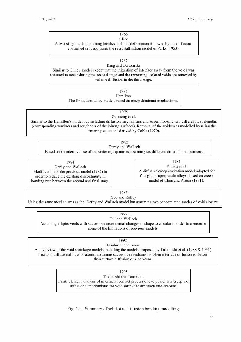
Fig. 2-1: Summary of solid-state diffusion bonding modelling.
1992 Takahashi and Inoue
An overview of the void shrinkage models including the models proposed by Takahashi et al. (1988 & 1991) based on diffusional flow of atoms, assuming successive mechanisms when interface diffusion is slower
than surface diffusion or vice versa.
1989 Hill and Wallach
Assuming elliptic voids with successive incremental changes in shape to circular in order to overcome some of the limitations of previous models.
1967
King and Owczarski Similar to Cline's model except that the migration of interface away from the voids was
assumed to occur during the second stage and the remaining isolated voids are removed by volume diffusion in the third stage.
1966 Cline
A two-stage model assuming localized plastic deformaion followed by the diffusion-controlled process, using the recrystallisation model of Parks (1953).
1987 Guo and Ridley
Using the same mechanisms as the Derby and Wallach model but assuming two concomitant modes of void closure.
1984 Derby and Wallach
Modification of the previous model (1982) in order to reduce the existing discontinuity in
bonding rate between the second and final stage.
1984 Pilling et al.
A diffusive creep cavitation model adopted for fine grain superplastic alloys, based on creep
model of Chen and Argon (1981).
1982 Derby and Wallach
Based on an intensive use of the sintering equations assuming six different diffusion mechanisms.
1975 Garmong et al.
Similar to the Hamilton's model but including diffusion mechanisms and superimposing two different wavelengths (corresponding waviness and roughness of the joining surfaces). Removal of the voids was modelled by using the
sintering equations derived by Coble (1970).
1973 Hamilton
The first quantitative model, based on creep dominant mechanisms.
1995 Takahashi and Tanimoto
Finite element analysis of interfacial contact process due to power law creep; no diffusional mechanisms for void shrinkage are taken into account.
Chapter 2 Literature survey
10
2.2 Theoretical aspects of transient liquid phase (TLP) diffusion
bonding
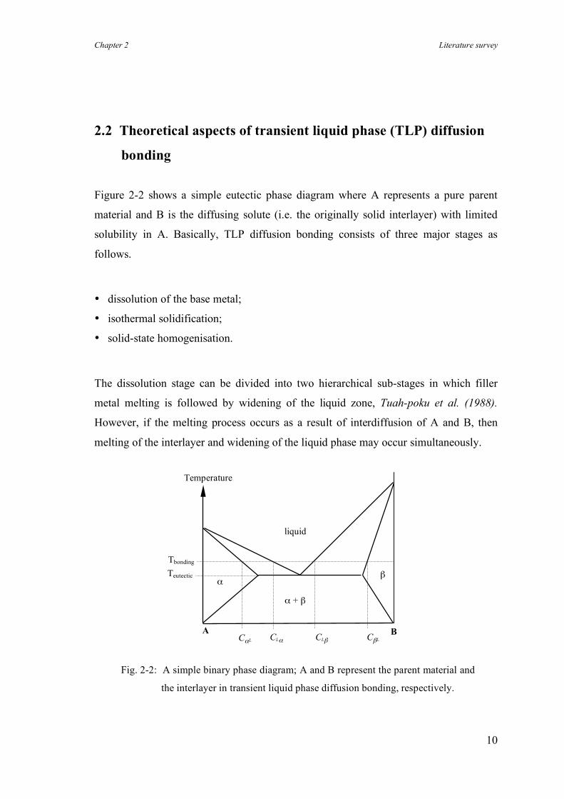
Figure 2-2 shows a simple eutectic phase diagram where A represents a pure parent
material and B is the diffusing solute (i.e. the originally solid interlayer) with limited
solubility in A. Basically, TLP diffusion bonding consists of three major stages as
follows.
• dissolution of the base metal;
• isothermal solidification;
• solid-state homogenisation.
The dissolution stage can be divided into two hierarchical sub-stages in which filler
metal melting is followed by widening of the liquid zone, Tuah-poku et al. (1988).
However, if the melting process occurs as a result of interdiffusion of A and B, then
melting of the interlayer and widening of the liquid phase may occur simultaneously.
Fig. 2-2: A simple binary phase diagram; A and B represent the parent material and
the interlayer in transient liquid phase diffusion bonding, respectively.
Teutectic Tbonding
Temperature
A
liquid
α
CLα CαL B CLβ CβL
β
α + β
Chapter 2 Literature survey
11
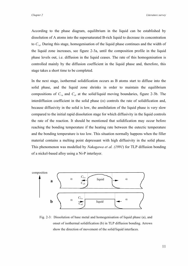
According to the phase diagram, equilibrium in the liquid can be established by
dissolution of A atoms into the supersaturated B-rich liquid to decrease its concentration
to CLα. During this stage, homogenisation of the liquid phase continues and the width of
the liquid zone increases, see figure 2-3a, until the composition profile in the liquid
phase levels out, i.e. diffusion in the liquid ceases. The rate of this homogenisation is
controlled mainly by the diffusion coefficient in the liquid phase and, therefore, this
stage takes a short time to be completed.
In the next stage, isothermal solidification occurs as B atoms start to diffuse into the
solid phase, and the liquid zone shrinks in order to maintain the equilibrium
compositions of CLα and CαL at the solid/liquid moving boundaries, figure 2-3b. The
interdiffusion coefficient in the solid phase (α) controls the rate of solidification and,
because diffusivity in the solid is low, the annihilation of the liquid phase is very slow
compared to the initial rapid dissolution stage for which diffusivity in the liquid controls
the rate of the reaction. It should be mentioned that solidification may occur before
reaching the bonding temperature if the heating rate between the eutectic temperature
and the bonding temperature is too low. This situation normally happens when the filler
material contains a melting point depressant with high diffusivity in the solid phase.
This phenomenon was modelled by Nakagawa et al. (1991) for TLP diffusion bonding
of a nickel-based alloy using a Ni-P interlayer.
Fig. 2-3: Dissolution of base metal and homogenisation of liquid phase (a), and
onset of isothermal solidification (b) in TLP diffusion bonding. Arrows
show the direction of movement of the solid/liquid interfaces.
b CLα
CαL α α
liquid
CLα
CαL α α liquid a
composition
Chapter 2 Literature survey
12
In the solid-state homogenisation stage, the concentration gradient of solute around the
interface declines. This is due to further diffusion of solute into the base material.
Theoretically, the chemical composition of the area adjacent to bond line could
approach that of the parent material.
In addition to the stages mentioned above, MacDonald & Eagar (1992) introduced
another stage, termed stage 0, which accounts for the effects of a low heating rate,
discussed by Niemann & Garrett (1974a) and Nakagawa et al. (1991). They showed
that a low heating rate may lead to insufficient liquid formation due to diffusion of the
filler material into the bulk of base metal before the eutectic temperature is reached.
Finally note that there is a difference between conventional brazing and TLP diffusion
bonding processes. The liquid phase in a brazing process wets the base metal and
solidifies only when the interface temperature decreases. In TLP diffusion bonding,
however, interdiffusion between the liquid phase and the base metal leads to a change in
the composition of the liquid phase and, consequently, to isothermal solidification. The
bonding temperature is usually determined by the temperature at which the liquid phase
forms, i.e. it is slightly above the corresponding eutectic temperature.
Modelling of TLP diffusion bonding
In light of the increasing use of TLP diffusion bonding for joining heat resistant
materials and titanium alloys in recent years, some attempts have been made to model
this process using analytical and numerical approaches. Some are reviewed below.
As mentioned before, TLP bonding uses the reduced liquidus temperature that occurs in
eutectic or peritectic alloy systems. Tuah-poku et al. (1988) analysed theoretical aspects
of TLP bonding associated with a simple eutectic phase diagram, using the binary
system of silver-copper. Based on earlier work of Lesoult (1976) and Sekerka (1975),
they studied TLP diffusion bonding in four distinct stages wherein the composition of
each phase was determined by the phase diagram, assuming local equilibrium at the
solid/liquid interface. However, for the sake of simplicity in this mathematical
calculation, the interdiffusion coefficients were assumed to be independent of chemical
composition. Also, the difference between the partial molar volumes of each element in
Chapter 2 Literature survey
13
existing phases was neglected, so it was possible to use Fick's diffusion laws in terms of
mole fractions. Finally, because of the small thicknesses of the interlayers used in this
process (normally not more than 100 µm), the effect of convection in the liquid phase
was neglected.
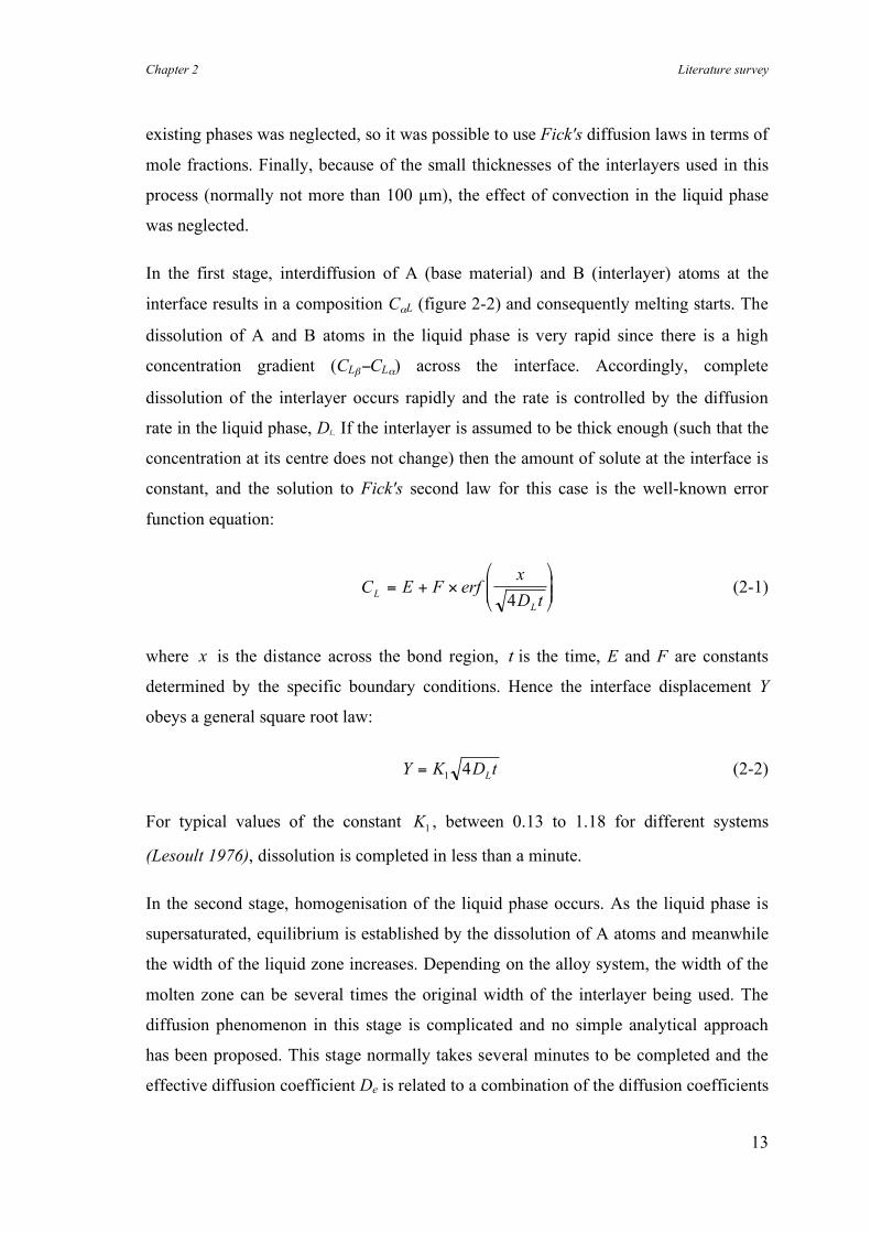
In the first stage, interdiffusion of A (base material) and B (interlayer) atoms at the
interface results in a composition CαL (figure 2-2) and consequently melting starts. The
dissolution of A and B atoms in the liquid phase is very rapid since there is a high
concentration gradient (CLβ−CLα) across the interface. Accordingly, complete
dissolution of the interlayer occurs rapidly and the rate is controlled by the diffusion
rate in the liquid phase, DL. If the interlayer is assumed to be thick enough (such that the
concentration at its centre does not change) then the amount of solute at the interface is
constant, and the solution to Fick's second law for this case is the well-known error
function equation:
C E F erfx
D tL
L
= + !"
#$$
%
&''
4 (2-1)
where x is the distance across the bond region, t is the time, E and F are constants
determined by the specific boundary conditions. Hence the interface displacement Y
obeys a general square root law:
Y K D tL
=14 (2-2)
For typical values of the constant K1, between 0.13 to 1.18 for different systems
(Lesoult 1976), dissolution is completed in less than a minute.
In the second stage, homogenisation of the liquid phase occurs. As the liquid phase is
supersaturated, equilibrium is established by the dissolution of A atoms and meanwhile
the width of the liquid zone increases. Depending on the alloy system, the width of the
molten zone can be several times the original width of the interlayer being used. The
diffusion phenomenon in this stage is complicated and no simple analytical approach
has been proposed. This stage normally takes several minutes to be completed and the
effective diffusion coefficient De is related to a combination of the diffusion coefficients
Chapter 2 Literature survey
14
in both the liquid and solid phases. It is worth noting that the effect of pressure on the
width of the liquid zone has been neglected in this analysis; see discussion in Chapter 6.
Isothermal solidification occurs in the third stage and the liquid zone starts to shrink as
B atoms diffuse into the solid A. Then, the interdiffusion coefficient Dα in the ! phase
controls the rate of solidification. Hence, this stage is much slower than the two
previous stages. Based on the original work of Sekerka (1975), the time required for
complete solidification and the effect of the bonding temperature on it were also
investigated by Tuah-poku et al. (1988). The solute distribution during the
homogenisation stage can be modelled using the basic equations for diffusion in a solid
phase.
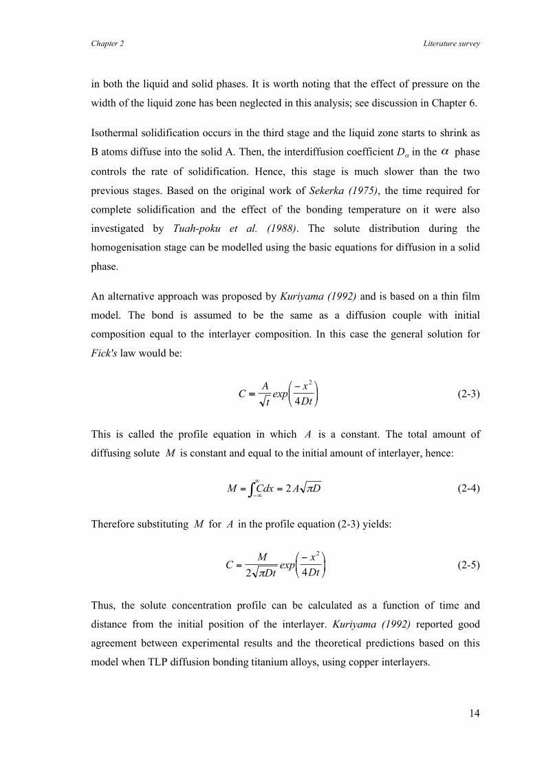
An alternative approach was proposed by Kuriyama (1992) and is based on a thin film
model. The bond is assumed to be the same as a diffusion couple with initial
composition equal to the interlayer composition. In this case the general solution for
Fick's law would be:
CA
t=
!"
#$
%
&'exp
x
Dt
2
4 (2-3)
This is called the profile equation in which A is a constant. The total amount of
diffusing solute M is constant and equal to the initial amount of interlayer, hence:
M Cdx A D= =!"
"
# 2 $ (2-4)
Therefore substituting M for A in the profile equation (2-3) yields:
CM
Dt
x
Dt=
!"
#$
%
&'
2 4
2
(exp (2-5)
Thus, the solute concentration profile can be calculated as a function of time and
distance from the initial position of the interlayer. Kuriyama (1992) reported good
agreement between experimental results and the theoretical predictions based on this
model when TLP diffusion bonding titanium alloys, using copper interlayers.
Chapter 2 Literature survey
15
The analytical approaches describe the bonding process using a number of hierarchical
and discrete stages. Actually, some of these steps occur simultaneously. For example
solute homogenisation in the bulk of the base metal starts immediately after the
solidification of a few atomic layers at each of the two interfaces, while the liquid phase
still exists at the centre of the bonding region. Also, these approaches rely on the
approximate solutions for diffusion equations, e.g. error function equations. Zhou et al.
(1995) reviewed the analytical approaches and proposed numerical simulations for TLP
diffusion bonding. They concluded that, in contrast to analytical solutions, a numerical
simulation has a key advantage in treating the bonding stages (i.e. dissolution,
solidification and homogenisation) as interdependent sequential processes.
Nakagawa et al. (1991) developed a numerical analysis in which the base metal
dissolution between the melting temperature and the bonding temperature of nickel,
using Ni-P filler metal, was studied. An explicit finite difference method was employed,
using a mass balance technique, to determine the location of the solid/liquid interface.
According to their work, at very low heating rates, isothermal solidification of the liquid
phase can occur between the melting temperature of the filler material and the bonding
temperature. Zhou (1994) developed a fully implicit finite difference model to calculate
the solute distribution and the location of the solid/liquid interface when TLP diffusion
bonding nickel base metal using a Ni-P 19 at.% interlayer. The well-known Fick’s first
and second diffusion laws were used as the governing differential equations in order to
determine the interface movement and the solute diffusion field, respectively. The finite
difference expression for the nodes near to the moving boundary were estimated using
Crank’s approximation.
The results of both of these numerical approaches showed that the surface areas under
the curves of solute versus distance from the centreline remained constant during the
base metal dissolution and isothermal solidification. This is a direct and obvious
consequence of the use of Fick’s laws which is based on the conservation of solute
during a diffusion process. However, the use of these equations in terms of atomic or
weight percents could be justified only if the partial molar volumes of phosphorus in all
three involved phases (i.e. the filler material with eutectic microstructure, the liquid
phase and the solidified single phase) are regarded as reasonably close. The molar
Chapter 2 Literature survey
16
volume of pure phosphorus is more than 2.5 times higher than that of pure nickel.
Therefore, this assumption that the partial molar volumes of phosphorus in all phases
are almost equal should have been more fully justified or explained since it can result in
unacceptable errors when calculating the locations of the solid/liquid interface. Note
that in Tuah-poku et al.’s approach, the molar volumes and physical properties of the
filler and base metals (i.e. copper and nickel) are almost the same, therefore the basic
equations could be expressed in terms of mole fractions without introducing a
substantial error.
Despite the advantages of numerical simulations for TLP diffusion bonding, the results
of these methods depend on the choice of arbitrary constants and parameters which are
used in the algorithm. Also, the numerical approaches generally are not reproducible nor
verifiable by other researchers. This is in contrast to analytical solutions, the accuracy of
which can be assessed directly without having to introduce additional parameters
necessary when running the numerical program, assuming the program itself is
accessible.
Modelling of TLP diffusion bonding of composites
Unfortunately, there are very few publications which consider the theoretical aspects
and modelling of the TLP diffusion bonding processes for composite materials. A
theoretical approach is required not only to optimise the bonding conditions but also to
ensure that any interfacial reactions between matrix and reinforcement are minimised.
In most metal matrix composites, diffusion of solute through the reinforcement particles
is expected to be negligible and these particles effectively reduce the cross sectional
area available to the diffusing elements. Thus, the effective diffusion coefficient of the
solute may depend on the volume fraction of reinforcement. Consequently, the
diffusion-controlled bonding mechanisms are affected by the reinforcement. This
hypothesis is in contrast to the results of a kinetic study on TLP diffusion bonding of
Al-6061/SiC composite, reported by Sabathier et al. (1994). They found out that the
presence of short-circuit paths for diffusion such as grain boundaries, subgrain
Chapter 2 Literature survey
17
boundaries, dislocations and ceramic/matrix interfaces enhanced the diffusion rate, and
the activation energy for atomic transport declined considerably.
Kuriyama (1992) investigated the effect of reinforcement on the TLP bonding of
titanium/SiC composites using a thin layer of copper to achieve bonding. In this system,
the high percentage of copper around the joint stabilised the β titanium phase. On the
other hand, the matrix further away from the bond line (where no copper was present)
transformed at the bonding temperature to the α titanium phase due to the diffusion of
carbon (an α stabiliser) out of the SiC particles. The solubility and diffusivity of copper
in the β phase are much higher than in the α phase and, therefore, the copper became
concentrated in the area close to the joint where the β phase was present and could
diffuse into the parent material (α phase) only very slowly. In contrast when TLP
diffusion bonding pure titanium, the absence of carbon did not allow the formation of
the α phase at the bonding temperature.
Accordingly, for the titanium/SiC composite, the profile of the copper distribution
became step-like in the region near to the bond line and then followed an error function
distribution further away. In contrast, in pure titanium with a single β phase structure,
the copper distribution followed an error function profile. Therefore, the bonding
behaviour of composites can be quite different from the corresponding un-reinforced
alloys and should be investigated individually.
Chapter 2 Literature survey
18
2.3 Solid-state diffusion bonding of aluminium alloys
Oxide layers on the faying surfaces may affect the ease of solid-state diffusion bonding
certain materials. Some oxide films either dissolve in the bulk of the metal or
decompose at the bonding temperature (e.g. those of many steels, copper, titanium,
tantalum and zirconium), and so metal-to-metal contact can be readily established at the
interface. Derby (1990) has indicated some of the possible chemical reactions which
may occur at the interface between a pure metal and simple oxides.
On the other hand, if the oxide film is chemically stable, as for aluminium-based
materials, then achieving a metallic bond can be difficult. The presence of a tenacious
and chemically stable surface layer of aluminium oxide is the main obstacle in most
welding processes for aluminium based materials. Different approaches have been
developed to overcome the oxide problem associated with the diffusion bonding of such
materials. A short description of these approaches and the reported results follow.
Imposing macroscopic plastic deformation
In solid-state diffusion bonding, a brittle and continuous oxide layer can be broken up
by imposing substantial plastic deformation. Metal-to-metal contact is thus promoted
because of local disruption of the oxide film on both faying surfaces. Early work on
deformation bonding (pressure bonding) of aluminium alloys by Cline (1966) and
recent work by Urena et al. (1995) both showed that about 40% deformation is required
to produce bonds with reasonable strengths. Cline also studied the effects of joint design
and surface condition on the strengths of Al-6061 bonds, in which grooves with
different depths were machined on the faying surfaces to provide a low initial contact
area with high local pressure. The highest tensile bond strength, of 110 MPa, was
obtained with a 1.5 mm groove depth and 50% deformation.
Enhancing microplastic deformation of the surface asperities
Chapter 2 Literature survey
19
An alternative approach to overcoming the oxide problem in solid-state diffusion
bonding is to use a fairly rough surface finish, which may lead to higher bond strengths
compared to polished surfaces. The rougher the surface the more the plastic deformation
on the asperities, therefore more oxide fracture occurs and consequently metal-to-metal
bonding is improved. Ricks et al. (1990) studied the effect of surface roughness on the
shear strength of Al-8090 bonds. Despite a considerable scatter in results, it was
concluded that higher bond strengths were achieved when a rougher surface preparation
was adopted. This is probably due to the higher deformation of the surface asperities on
a rough surface which leads to more rupture of the surface oxide, in comparison with a
smooth surface. These results are consistent with those reported by Tensi & Wittmann
(1990) in which the influence of surface preparation on the bond strength of Al-7475
bonds was investigated.
Enjo et al. (1978) used electrical resistance measurements of Al-Al bonds to show that
faying surfaces treated by coarse emery paper produced more metallic bonds than
smooth faying surfaces. The effect of the shape of asperities (asperity angle) on the
interfacial contact process has been recently modelled by Takahashi & Tanimoto
(1995a), although the effect of surface oxide layer was not considered. The model was
reasonably verified by conducting some experiments on oxygen-free copper, see
Takahashi & Tanimoto (1995b).
In contrast, Harvey et al. (1985) showed that polishing the silver cladding on Al-7010
improved the bond strength, compared with the bonds made using as-clad samples. The
specimens were argon ion sputter cleaned before the deposition of the silver layer,
therefore there was no aluminium oxide between the cladding and the base metal (see
Harvey et al. (1986) for experimental details). This inconsistency regarding the effect of
surface roughness on bond strength, is probably due to the different properties of the
surface layers of silver and aluminium. The surfaces of silver coated samples are
virtually oxide free, so improving the surface finish increases the metal-to-metal contact
at the interface. In contrast, in the case of uncoated aluminium faying surfaces, bond
strengths improve by the generation of oxide-free surfaces as a result of the local
deformation of the asperities. Low temperature solid-state bonding of copper, using
different surface preparations, was investigated by Nicholas et al. (1990). There was a
Chapter 2 Literature survey
20
significant reduction in the bond strength as the surface roughness increased, which is
consistent with the above conclusion regarding the effect of surface roughness on the
bonding behaviour of materials without oxide layers.
Use of interlayers and the effect of alloying elements
Barta (1964) examined a variety of interlayers (silver, gold, nickel, aluminium, tin,
zinc, iron, copper and magnesium) for low temperature diffusion bonding of Al-7075.
The interlayers were in the form of electroplated, vacuum deposited, plasma sprayed,
loose foils and clad Al-7072. Bonding was carried out under a very high pressure of 165
MPa in the temperature range 150-230°C. The use of most interlayers resulted in either
very poor bonds or no bonding. The highest bond strength achieved, using a clad
aluminium sample, was 76 MPa; improving to 110 MPa after post bond heat treatment.
However, low temperature diffusion bonding may be of benefit for high precision
joining where mechanical properties are not a crucial factor. Bienvenu & Koutny (1990)
manufactured a small component for a detector, using a silver coating to sandwich a
thin foil of an Al-Mg alloy (8 µm) between two thicker templates (50 µm) of the same
material at 400°C.
Maddrell & Wallach (1990) studied the effects of active alloying elements such as
magnesium and lithium on the morphology of the surface Al2O3 layer, when bonding
aluminium-based alloys. According to this research, these active elements decompose
and break up the aluminium oxide layer at the interface. A good correlation between
bond strength and the extent of broken oxide was observed, leading to the conclusion
that the greater the concentration of these elements, the greater the disruption of the
oxide layer and, consequently, higher bond strengths. Kotani et al. (1996a&b) found
that increasing the bonding temperature changed the amorphous oxide layer gradually
into crystalline particles. The temperature at which the amorphous oxide layer was
annihilated could be decreased by additions of magnesium to the alloy matrix.
Ricks et al. (1990) investigated the effect of some alloying elements on the bond
strengths of Al-8090, using aluminium alloy interlayers containing gallium, lithium and
magnesium with thicknesses of about 100 µm. The use of Al-Mg interlayers improved
Chapter 2 Literature survey
21
the bond shear strength by up to 50% in comparison with bonds made using pure
aluminium interlayers, i.e. from 100 to 150 MPa. In recent work, Church et al. (1996)
conducted tensile tests on miniature Al-Li 8090 bonds. A scanning Auger microprobe
was used to analyse the elemental composition of the fractured surfaces. Despite the
presence of oxygen in all samples, bonds with high strengths contained lithium and
aluminium whereas lithium was not detected on the fracture surfaces of the poor bonds.
It was concluded that lithium possibly reacted with aluminium oxide to form a
thermodynamically more stable oxide, therefore the bond strength was increased due to
the disruption of the initial oxide layer. Dunford & Partridge (1990, 1991 & 1992) and
Gilmore et al. (1991) concluded that the lithium in Al-8090 modified the aluminium
oxide into discontinuous and less stable Li-Al spinels during the bonding process. TEM
examination of the interface proved the absence of the continuous oxide layer in Al-
8090 bonds. However, according to Maddrell & Wallach (1990), the native oxide layer
was not substantially disrupted and the bond line remained decorated by semi-
continuous layer of oxide which reduced the bond strength. Based on TEM observation,
Urena et al. (1996a) proposed that interface oxide particles may not be the main cause
responsible for pinning down the interface, but that Al3Zr, which was detected along the
grain boundaries in the parent material (Al-8090) as well as at the bond interface,
suppresses the migration of the interface.
All the results, mentioned above are consistent with Maddrell et al.’s (1989) results
showing that the presence of some alloying elements, such as Mg and Li can improve
bond strength. Similar results had been reported earlier by Dray (1985).
Non-conventional bonding and testing methods
Enjo & Ikeuchi (1984) carried out the diffusion bonding of Al-2017 in the temperature
range above the solidus line but below the liquidus line, where solid and liquid phases
coexist (i.e. 580°C). In spite of the formation of a liquid phase, this method was referred
to as solid-state diffusion bonding. It should be mentioned that, in contrast to transient
liquid phase, solidification in this method occurs as a result of cooling, as in brazing. It
was assumed that the formation of the liquid phase could aid the disruption of the oxide
layer and provide intimate contact at the interface. Preferential melting at the bond
Chapter 2 Literature survey
22
interface and the grain boundaries was directly observed at the bonding temperature.
The volume fraction of the liquid phase proved a crucial factor. The maximum shear
strength (270 MPa) was achieved when the volume fraction of the liquid phase was
2~3%. The tensile strength of the joint was increased to 400 MPa by a post bond heat
treatment. However, when the volume of the liquid phase exceeded 3%, grain boundary
cracking occurred and the bond line was associated with a large amount of porosity. No
explanation was given for the fact that, despite the formation of the liquid phase at the
grain boundaries, the base material could still withstand a bonding pressure of 1 MPa.
Because of the high temperature used, the detrimental effects of melting on the
microstructure and shape of the base material are expected to be substantial. In practical
terms, the process does not seem viable as a minor miscarriage during the bonding
process would destroy the part which is heated up to its solidus temperature.
Yokota et al. (1997) developed a new method based on a combination of solid-state
diffusion bonding and friction welding to join Al-6061 and Al-6060/SiC MMC. In this
method, a torsional force was exerted while an axial force was acting on the parts to be
joined. One of the parts had a conical end in order to exclude the worn oxide film from
the interface. The specimens were heated using a high frequency induction system and
the axial load applied, while the torsional force was used to rotate the upper part at a
constant speed of 6 rpm. The maximum tensile strength of the bonds, made applying 90
MPa axial pressure at 250°C, was 200 MPa. An important advantage of this method
over diffusion bonding and friction welding is claimed to be the low bonding
temperature (250-350°C) and short bonding time (~5 minutes), which reduces the
plastic deformation during the bonding process. However, in contrast to diffusion
bonding, the method is only applicable to parts with certain shapes (preferably with
round cross section) which should be machined to provide conical ends. Also, unlike
friction welding which is carried out in air, the new method requires a vacuum.
Dunford & Partridge (1987, 1990, 1991 & 1992) have reported the highest bond
strengths for Al-8090, i.e. 181 to 202 MPa for lap shear tests with an overlap of 2 mm.
However, the shear strengths decreased drastically (~50%) for overlaps of about 4 mm.
Tensi et al. (1989) also carried out lap shear tests on Al-7475 with a very short overlap
length of 1.5 mm; a maximum shear strength of 410 MPa was reported. However, the
Chapter 2 Literature survey
23
reliability and practicality of the methods which are evaluated under extreme testing
conditions (e.g. shear test on the joint with an overlap of less than 2 mm) are doubtful.
Cailler et al. (1991) used high speed dynamic loading equipment to study the bond
strength, failure elongation and failure energy of Al-2017 diffusion bonds. The
projectile speed was 30 m/s and the time duration for transmitting the load was less than
114 µs. The tensile strengths of the joints in the as-bonded condition reached 290 MPa,
in comparison with 300 and 460 MPa which were the tensile strengths of the parent
material in the as-bonded and in the fully aged-hardened condition, respectively. The
failure elongation of the bonded samples was about one third of the parent material with
the same thermal cycle. Debbouz & Navai (1997) adopted a similar approach to study
the effect of bonding conditions on the mechanical properties of Al-2017 bonds. In both
cases, it is not mentioned why the bonds were not post bond treated to achieve a fully
hardened condition rather than heat treating the parent material. If that had been done,
the comparison between the mechanical properties of the bonds and the parent material
would be more conclusive.
Summary
It can be concluded that, despite the vast research on the solid-state diffusion bonding of
aluminium alloys, this method has failed to reliably produce high strength joints. The
presence of a wide scatter in bond strengths is a particularly discouraging feature of
solid-state bonding. Non-conventional solid-state diffusion bonding processes rely on
extreme bonding conditions or require complicated equipment in an attempt to improve
reliability; therefore these approaches tend to have very restricted application.
Chapter 2 Literature survey
24
2.4 TLP diffusion bonding of aluminium alloys
As discussed before, the formation of a liquid phase in TLP diffusion bonding could
assist the disruption of an oxide layer and thus promote metallic contact. Therefore TLP
diffusion bonding of aluminium-based materials has been of interest. The results of
previous research on this method are discussed with respect to the type of interlayer
used. Due to the importance of aluminium-based metal matrix composites, the joining
of these materials is reviewed in the next section.
Zinc based interlayers
Ricks et al. (1990) investigated TLP diffusion bonding of Al-8090 sheets using a roll
clad interlayer with a chemical composition of Zn−1 wt.% Cu. This method was based
on a combination of roll bonding and TLP diffusion bonding. A very careful surface
preparation technique including mechanical and chemical cleaning was conducted to
ensure good bonding between the cladding and the substrate. The rolling conditions
were also optimised to obtain the required mechanical properties. Reproducible bond
shear strengths in the order of 100-150 MPa were reported together with considerable
improvements in hot peel strength compared with solid state bonding. It was concluded
that precipitation of zinc on the grain boundaries, on both sides of the interface, limited
the bond strength. The zinc-rich areas remained unaffected after post bond heat
treatment. Due to the rolling stage, this technique is only applicable for joining sections
which can be roll bonded, e.g. plates.
The use of a thin zinc interlayer of 1.3 µm thickness for diffusion bonding Al-8090
(virtually without Li and Mg) and Al with 5 at.% Mg was not satisfactory, Maddrell
(1989). Unfortunately, because of the different surface preparation techniques and
bonding conditions between this work and that of Ricks et al., no reliable conclusion
can be drawn.
Chapter 2 Literature survey
25
Livesey & Ridley (1990) also investigated the effect of ion beam cleaning on bond
strength. The average shear strength of Al-8090 bonds using 3 µm thick zinc interlayers
was 164 MPa without ion beam cleaning, although that could be increased up to 190
MPa by ion beam cleaning before sputter coating. Despite an 18% scatter in the former
case, these strengths are 40 to 50 MPa higher than those obtained by Ricks et al. in
which a thicker zinc cladding of about 50 µm had been rolled on each side of the
aluminium being joined.
Silver interlayers
Dray (1985) used silver interlayers with a thickness of 0.25 µm on each faying surface
when bonding Al-6061. A two stage bonding sequence was used. Initially, bonding was
at a temperature about 5°C above the eutectic temperature of aluminium-silver (572 °C)
for 5 minutes using a pressure of 1.25 MPa. The second stage was for 35 minutes at
450°C using a pressure of 2.5 MPa. Tensile bond strengths equivalent to the parent
material were reported, although the impact strengths were one third that of the parent
material. Based on rough diffusion calculations, Dray estimated that the formation of a
liquid phase was unlikely. The combination of the heating rate and the interlayer
thickness was such that silver could diffuse rapidly away from the interface during
heating and so the eutectic composition could not be established when the eutectic
temperature eventually was reached. TEM observations did not show any clear evidence
of melting at the interface. Dray recommended the use of thicker interlayers and/or a
faster heating rate to achieve true TLP diffusion bonding.
Urena & Dunkerton (1989) tried thicker silver interlayers (1, 12.5, and 25 µm) when
bonding Al-8090. A maximum tensile strength of about 110 MPa for a 12.5 µm
interlayer was reported. The presence of a high volume of voids in the case of a 1 µm
interlayer, and the precipitation of thick brittle intermetallics in the case of a 25 µm
interlayer, were given as the reasons for the poor mechanical properties. Despite the
formation of a liquid phase at the interface, the bond strengths were lower than those
reported by Dray.
Copper interlayers
Chapter 2 Literature survey
26
Dray (1985) used 1 µm copper interlayers for the TLP diffusion bonding of Al-6061
and obtained tensile and impact strengths close to the strength of the parent material.
The bonding cycle included 10 minutes at 555 °C followed by 30 minutes at 450 °C.
The presence of a dendritic pattern at the interface was clear evidence of melting. TEM
and EPMA investigations revealed copper-rich precipitation in the matrix away from
the bond line and also segregation of magnesium and silicon, as Mg2Si particles, at the
interface.
Maddrell (1989) examined TLP diffusion bonding of Al-8090 (virtually without Mg
and Li) and Al with 5 at.% Mg, using the same interlayer. In the former case, a thin
oxide layer was apparent along most of the bond line although it was not discernible in
some parts. These bonds were not shear tested, However, shear strengths as high as 170
MPa were measured for Al-5 at.% Mg despite the clearly discernible bond-line.
Maddrell concluded that the interfacial energy between the oxide particles and the
liquid phase has a key role in the final oxide distribution pattern.
Dunford et al. (1990) studied the effect of various overlap lengths on bond shear
strength, using ion beam cleaning before copper deposition. The shear strength of Al-
8090 bonds with an overlap length of less than 3 mm was 191± 8 MPa but it declined to
about 70 MPa for overlaps greater than 4 mm (see also Gilmore et al. 1991). However,
the surface preparation method, used for oxide removal before copper coating, restricts
the application of the method.
Summary
TLP diffusion bonding, as a method for joining aluminium alloys, resulted in bonds
with higher strengths than those made using solid-state diffusion bonding. However, the
reported bond strengths and/or associated scatter in the strength have not been
satisfactory and further work is required to improve bond quality.
Chapter 2 Literature survey
27
2.5 Joining aluminium metal matrix composites
Great attention has recently been paid to the production and application of aluminium
metal matrix composites (Al-MMCs) because of their superior mechanical properties
compared with un-reinforced aluminium alloys, Lloyd (1994). The most significant
property of these Al-MMCs is their high elastic modulus. Elastic modulus is the
limiting criterion in the design of components that fail by some sort of elastic instability,
e.g. buckling, and it does not normally change significantly by alloying or hardening
processes. The elastic modulus for Al/SiC composites increases almost linearly on
increasing the volume fraction of SiC particles, Peel et al. (1995). High stiffness,
strength and also wear resistance are the main advantages of this composite.
Unfortunately, despite the potentially vast applications for aluminium-based
composites, relatively few attempts have been made to develop a reliable joining
process. Thus, the lack of a reliable and economical joining technique has restricted the
application of these materials and more investigation is required.
Ellis (1996) reviewed the joining techniques developed for Al-MMCs. Generally, fusion
welding is not successful for joining Al-MMCs. Non-uniform distribution of the
reinforcement particles in the weld zone and precipitation of plate-like brittle
compounds, e.g. aluminium carbide in Al/SiC-MMCs, are major problems when fusion
welding. Manipulation of the molten pool was difficult and even filler materials with
high fluidity would not mix with the viscous molten composite. In some respects, the
welding described above was more similar to brazing rather than fusion welding, as
almost no reinforcement particles were observed in the weld bead. In some cases, very
low corrosion resistance has been reported, e.g. where aluminium carbide forms from
dissociated SiC particles and is corroded in the presence of water very rapidly, releasing
acetylene gas. However, matrix-particle chemical reaction and particle segregation can
be reduced with careful control of heat input and consumables when using TIG and
MIG welding processes. Other fusion welding processes such as laser and electron
beam welding were also not satisfactory, Ellis (1996). Friction welding seems a
promising technique for joining these materials providing that geometrical restrictions
on components and the associated massive deformation can be tolerated.
Chapter 2 Literature survey
28
Fewer detrimental reactions are associated with solid and liquid state diffusion bonding
as they can be carried out at a lower range of temperatures than fusion welding
processes. Ellis (1992) reported the results of solid-state diffusion bonding of Al-
7075/SiC 20 vol.% at constant temperature of 500°C using silver, copper and
aluminium interlayers with different thicknesses. Although the bonding temperature
was lower than the eutectic temperature of the binary Al-Cu system, local melting
occurred at the bond line. High particle density and an ample number of defects were
observed. All bonds made using copper interlayers failed during machining. In contrast,
no trace of silver and no evidence of particle enrichment were observed when using
silver interlayers. As for aluminium interlayers, there was no sign of diffusion to or
from the interlayer. The shear test results showed that already low shear strengths in the
as-bonded condition decreased after a full heat treatment.
Urena et al. (1995) used Al-8090, Supral 100 (superplastic Al-Cu alloy) and pure silver
as interlayers when solid-state diffusion bonding Al-2124/SiC. A shear strength of 70
MPa was obtained using Al-8090 interlayers with plastic deformation in the range of 20
to 30%. Strengthening of the base material adjacent to the interlayer is attributed to the
presence of lithium within the interlayer. The silver and Supral interlayers resulted in
much lower bond strengths. In another investigation, the bond strengths reported for Al-
2014/SiC using Al-8090 and silver interlayers were 50 and 36 MPa, respectively, Urena
et al. (1996b). All the bond strengths reported were well below the strength of the
corresponding parent material.
There are a few reports on the TLP diffusion bonding of aluminium metal matrix
composites. Niemann & Garrett (1974b) used copper interlayers for the eutectic
bonding of boron-aluminium monolayer foils. An intensive investigation on different
surface preparation techniques was carried out, using an ellipsometer to measure the
thickness of the oxide layer. This instrument has sufficient sensitivity to detect a
monolayer of oxide on a metallic surface. A copper coating of about 20 µm thickness
was subsequently deposited on both sides of each monolayer after ion beam cleaning.
Bonding was carried out under 1.7 MPa pressure at a temperature slightly above the Al-
Cu eutectic temperature. Although the formation of a liquid phase was isothermal
(based on the interdiffusion of copper atoms in the aluminium matrix), solidification of
Chapter 2 Literature survey
29
the liquid phase was induced in a non-isothermal manner, i.e. by decreasing the
temperature just after formation of the liquid phase. Satisfactory results were reported
with minimal degradation of boron filaments. As mentioned before, the use of ion-beam
cleaning to remove the oxide layer substantially restricts the development of this
technique on a commercial scale.
Partridge & Dunford (1991) studied the effects of particle size, distribution and
symmetry on the different types of interface which can form at the bond line in
composite materials. They showed that bond strength is influenced by the area fractions
of the particle/particle, particle/matrix and matrix/matrix interfaces. Insertion of an
interlayer, when solid-state bonding, may increase or decrease the particle/matrix area
fraction depending on the particle distribution and symmetry on the faying surfaces.
Details of this approach are discussed in section 4.4. A shear strength of about 100 MPa
was reported for the solid-state diffusion bonding of Al-8090/SiC 20 vol.% with an
overlap of 2 mm, Dunford & Partridge (1992). Using 80-100 µm thick interlayers of
Al-8090, increased the bond strengths up to 170 MPa. TLP diffusion bonding, using 10
µm copper interlayers, resulted in a higher shear strength of >170 MPa. No data are
available for the parent material shear strength as adopting the same shear test
conditions was not possible. Much lower shear strengths are expected when testing with
overlap lengths more than 2 mm, see section 2.4. Gomez de Salazar et al. (1997) used a
brazing filler material (Al-12 wt.% Si) for TLP diffusion bonding of two Al-6061/Al2O3
MMCs with 10 and 20 vol.% particle, and the maximum shear strengths were 87 and 65
MPa for the composites, respectively. Solid-state diffusion bonding of the same material
resulted in lower bond strengths, Escalera et al.(1997).
The effect of alloying elements on bond strength, such as Mg within an alloy interlayer,
was studied by Ikeuchi & Asano (1993). They used Al-Mg-Cu alloys, containing 0.5 to
2 wt.% Mg, as the interlayer for TLP diffusion bonding of an alumina-fibre reinforced
aluminium MMC to pure aluminium. The shear test results showed that the higher the
Mg content the higher the bond strength. Increasing the Mg content from 0.5 wt.% to 2
wt.% increased the tensile bond strength from 60 MPa to its maximum value of ~100
MPa. SEM observations showed a remarkable improvement in the fracture surfaces and
this is consistent with the measured shear strengths.
Chapter 2 Literature survey
30
Summary
Joining aluminium metal matrix composites, using either solid-state or fusion welding
processes, was found to be even more difficult than the bonding of unreinforced
aluminium alloys. This is mostly due to the detrimental effects of the bonding processes
on the reinforcement particles, e.g. undesirable decomposition or segregation of the
reinforcement at or about the bond line. As for aluminium alloys, the TLP diffusion
bonding of aluminium MMCs resulted in higher bond strengths than when using solid-
state diffusion bonding. However, the highest bond strengths, reported to date, are well
below the strengths of the parent materials. Moreover, due to the superplastic behaviour
of some of these composites at the bonding temperature (about 550°C when using a
copper interlayer), the bonding process is associated with substantial plastic
deformation.
Chapter 2 Literature survey
31
2.6 Diffusion bonding of aluminium-based materials in air
Reports on the diffusion bonding of aluminium-based materials in air are scant. Morley
& Caruso (1980) investigated the solid-state diffusion bonding of an aluminium silicon
casting alloy (Al-390) in air and nitrogen. The samples were silver coated in order to
prevent oxidation of the faying surfaces. The tensile strengths of the bonds made in
nitrogen were up to 57 MPa, whereas the bonds made in air had virtually no strength.
Ricks et al. (1989) modified the surface layers of Al-8090 to induce TLP diffusion
bonding in air. The base materials were roll-clad, using a zinc based alloy, to prevent
the oxidation of the faying surfaces during bonding. The cladding was followed by hot
and then cold rolling processes. Reproducible bonds with shear strengths of 100 to 120
MPa were reported. However, due to the pre-bonding procedure which requires
substantial changes in the initial shape of the parent material, the technique has limited
application. Moreover, the reported strengths are not high.
Livesey & Ridley (1990) used vapour deposited zinc interlayers for joining Al-7475, Al-
8090 and Supral 220 in air. The samples were chemically treated before the coating
process. The interlayer thickness varied from 1.5 to 6 µm and various bonding pressures
were examined. This investigation revealed that increasing the bonding pressure from 2
to 3 MPa, increased the bonding shear strength dramatically. However, despite a
relatively high average shear strength of 228 MPa for the Al-7475 bonds, using 3 µm
interlayers, the scatter in results was of the order of ±27%. The Al-8090 bonds had an
average shear strength of 164 MPa with a variation of ±23%. These values, surprisingly,
are higher than those obtained by Ricks et al. (1990) who used a thicker cladding of
about 50 µm zinc rolled on each side of the aluminium being joined in vacuum, see
section 2.4. This improvement may be attributed to the chemical treatment that Livesey
& Ridley (1990) adopted before coating. The TLP diffusion bonding of Supral 220
using the same method was not satisfactory.
Chapter 2 Literature survey
32
Pilling & Ridley (1987) tried solid-state diffusion bonding Al-7475. The samples were
chemically treated in NaOH and HNO3 and bonding was carried out in air. The bonds
produced had shear strengths in the range 30-150 MPa. The source of such a wide
variation in shear strength was not identified in their research.
Bushby & Scott (1993) used copper interlayers for the TLP diffusion bonding of pure
aluminium in air. Bonding was carried out under transient pressure with an initial value
of 3 MPa which was dropped down to about 1 MPa within the bonding time of 60
minutes. Bond shear strengths up to ~50 MPa were achieved. Increasing the initial
pressure up to 10 MPa resulted in bond shear strengths of 96 MPa. The use of the same
procedure for bonding Al/Nicalon (SiC fibre) composite in air was not successful
although a much higher initial pressure (i.e. 30 MPa) was applied. The shear strength of
the bonded composite in which 66% of the central area was bonded was 34 MPa.
Taking into account the unbonded area, this value was normalised to 51 MPa. In a
similar approach, a Cu-Ag eutectic alloy, instead of pure copper, was used as the
interlayer and the bonding temperature was decreased from 550 to 510°C, Bushby &
Scott (1995a). The use of the alloy interlayer resulted in similar strengths for the
composite bonds, though aluminium bonds had lower shear strengths (~65 MPa).
Bushby & Scott (1995b) used an interlayer of Al-2124 for solid-state diffusion bonding
Al-2124/SiC 30 vol.% composite in air. Bond shear strengths of about 110 MPa with a
wide scatter of ±45% were reported. This value is about 40% of the shear strength of the
composite.
Summary
TLP diffusion bonding in air resulted in low bond strengths with unreasonably high
scatter. In the most successful methods, the base materials were coated before bonding
(e.g. by Cu deposition or Zn roll-cladding) to prevent further oxidation of the faying
surfaces during TLP diffusion bonding in air. Even using these approaches, a wide
scatter of ±25% in strengths was reported. Obviously, due to the already unsatisfactory
results of solid-state diffusion bonding in vacuum, conducting the process in air has not
been developed.
Chapter 2 Literature survey
33
2.7 Summary
Diffusion bonding is a promising method for joining materials for which conventional
welding methods have proved unsuccessful. More than three decades of research on the
diffusion bonding of aluminium-based materials has resulted in a comprehensive
understanding of bond formation mechanisms and the problems associated with the
stable aluminium oxide film which hinders the formation of an ideal joint at the bond
line.
Solid-state diffusion bonding may result in high strength bonds if plastic deformation is
large enough to provide metal-to-metal contact as a result of oxide disruption on the
faying surfaces. The effects of alloying elements in either the base material or an
interlayer have been studied, and show that some alloying elements such as magnesium
enhance disruption of the oxide layer, leading to higher bond strengths.
Alternatively, transient liquid phase (TLP) diffusion bonding has been considered a
promising method for joining materials with stable oxide films due to the presence of a
liquid phase between two faying surfaces. As an example, the use of copper interlayers
has proved to be successful when joining some aluminium-based alloys and composites.
Despite a vast amount of research in this field, design engineers do not consider
diffusion bonding to be a reliable method for joining aluminium-based materials for
commercial applications. The bond strengths reported for these materials are lower than
the strengths of the corresponding parent materials. Also, a most discouraging feature of
diffusion bonding is the presence of an unreasonably wide scatter in the results; this
suggests that the method is an unreliable joining process for aluminium-based materials.
Achieving high strength bonds when using a complicated bonding process (such as ion
beam cleaning to remove the oxide film before TLP diffusion bonding) has very limited
application. Similarly, introducing a high amount of plastic deformation to improve the
bond strength confines the use of such an approach to applications where massive
deformations can be tolerated. The approaches which rely on the effect of alloying
elements, in order to improve the bond quality, cannot be employed for a vast range of
the materials which lack those particular elements.
Chapter 2 Literature survey
34
Despite several attempts to model TLP bonding, none has considered the real conditions
involved in a bonding process. For example, the effect of pressure as a crucial bonding
parameter has been neglected. However, the results of analytical approaches can be used
as guideline. The numerical simulations for TLP diffusion bonding were based on
unjustified and questionable assumptions and, at the moment, they are neither verifiable
nor can be used by other researchers.
Hence, in order to overcome the problems associated with the diffusion bonding of
aluminium-based materials, six new methods have been developed during this Ph.D.
research. A new analytical model and a numerical simulation for the fourth method is
also proposed.

Chapter 2 Literature survey
35
Appendix
Advantages and limitations of diffusion bonding are as follows.*
Advantages:
1. The process has the ability to produce high quality joints so that neither metallurgical
discontinuities nor porosity exist across the interface. An ideal diffusion bond is free
from flaws, oxide inclusions, voids and loss of alloying elements.
2. With properly controlled process variables, the joint would have strength and
ductility equivalent to those of the parent material.
3. Joining of dissimilar materials with different thermo-physical characteristics, which
is not possible by other processes, may be achieved by diffusion bonding. Metals,
alloys, ceramics and powder metallurgy products have been joined by diffusion
bonding.
4. Fairly high precision products can be manufactured without subsequent machining
because of the solid-state nature of the process and relatively low bonding pressures
required. This means that good dimensional tolerances for the products can be
attained.
5. Diffusion bonding of components with intricate shapes or cross sections is possible.
6. Heavy section parts can be joined by diffusion bonding without pre-heating.
7. Apart from the dimensions of the bonding machine, there is no limitation on the
number of joints which can be carried out simultaneously.
8. Excluding the heating stage, the time required for bonding is independent of the size
of bonded area.
* Welding Handbook of AWS (1976), Kazakov (1985), Houldcroft (1977) and Dray (1985)
Chapter 2 Literature survey
36
9. Reduction of sensitivity to corrosion has been reported in some diffusion bonded
alloys e.g. titanium and zirconium.
10.Apart from the initial investment, the consumable costs of diffusion bonding are
relatively low as no expensive solder, electrodes, or flux are required (although the
capital costs and the costs associated with heating for relatively long times may be
high).
11.Diffusion bonding is free from ultraviolet radiation and gas emission so there is no
direct detrimental effect on the environment, and health and safety standards are
maintained.
12.Automation is possible by computer controlling the basic variables of the diffusion
bonding e.g. time, temperature, and pressure.
Limitations:
1. Great care is required in the surface preparation stage. Excessive oxidation or
contamination of the faying surfaces would decrease the joint strength drastically.
Diffusion bonding of materials with stable oxide layers is very difficult. Production
of thoroughly flat surfaces and also precise fitting-up of the mating parts takes a
longer time than with conventional welding processes.
2. The initial investment is fairly high and production of large components is limited by
the size of the bonding equipment used.
3. Application of the force and heat in a vacuum or protective environment makes on-
site working difficult.
4. The suitability of this process for mass production is questionable, particularly
because of the long bonding times involved.
5. The lack of reliable data about joint behaviour, e.g. fatigue life or fracture toughness
etc., and also inadequate methods for non-destructive testing the joint quality
currently are problems, although it is expected they will be overcome in the future.
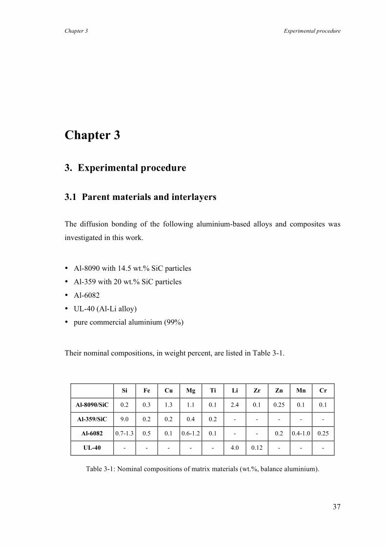
Chapter 3 Experimental procedure
37
Chapter 3
3. Experimental procedure
3.1 Parent materials and interlayers
The diffusion bonding of the following aluminium-based alloys and composites was
investigated in this work.
• Al-8090 with 14.5 wt.% SiC particles
• Al-359 with 20 wt.% SiC particles
• Al-6082
• UL-40 (Al-Li alloy)
• pure commercial aluminium (99%)
Their nominal compositions, in weight percent, are listed in Table 3-1.
Si Fe Cu Mg Ti Li Zr Zn Mn Cr
Al-8090/SiC 0.2 0.3 1.3 1.1 0.1 2.4 0.1 0.25 0.1 0.1
Al-359/SiC 9.0 0.2 0.2 0.4 0.2 - - - - -
Al-6082 0.7-1.3 0.5 0.1 0.6-1.2 0.1 - - 0.2 0.4-1.0 0.25
UL-40 - - - - - 4.0 0.12 - - -
Table 3-1: Nominal compositions of matrix materials (wt.%, balance aluminium).
Chapter 3 Experimental procedure
38
All the as-received materials were fully age-hardened and in the form of 25-40 mm
thick plates with the exception of the Al-6082 alloy which was supplied as 10 mm
diameter rod. The distribution of SiC particles in the matrix of the Al-8090/SiC
composite was found to be non-uniform and there were patchy areas with a relatively
low particle density, whereas the Al-359/SiC had a more uniform microstructure
(compare figures 4-6 and 4-7).
Two forms of copper interlayer were used in this work:
• pure copper (99.9%) foils in thicknesses of 3, 7, and 12.5 µm;
• sputter coated copper with a thickness of about 0.7, 1, and 1.5 µm on each surface.
Sputter coating of the faying surfaces was carried out after grinding with silicon carbide
paper of 1200 grit followed by washing in ethanol and rinsing in acetone. The system
was liquid nitrogen cooled and ion beam cleaning was not conducted prior to sputter
coating. Typical sputter coating conditions for deposition of about 1 µm copper are as
follows.
• base pressure: 5 × 10⁻⁹ mbar (5 × 10⁻⁷ Pascal)
• argon pressure: 1.2 Pascal
• target power: 31 Watt
• target substrate distance: 36 mm
• time: 22 minutes
The thickness of the coating was measured by surface profilometer. The adhesion
between the substrate and the coating was poor, so these interlayers can be considered
to act in a similar way to the foil interlayers.
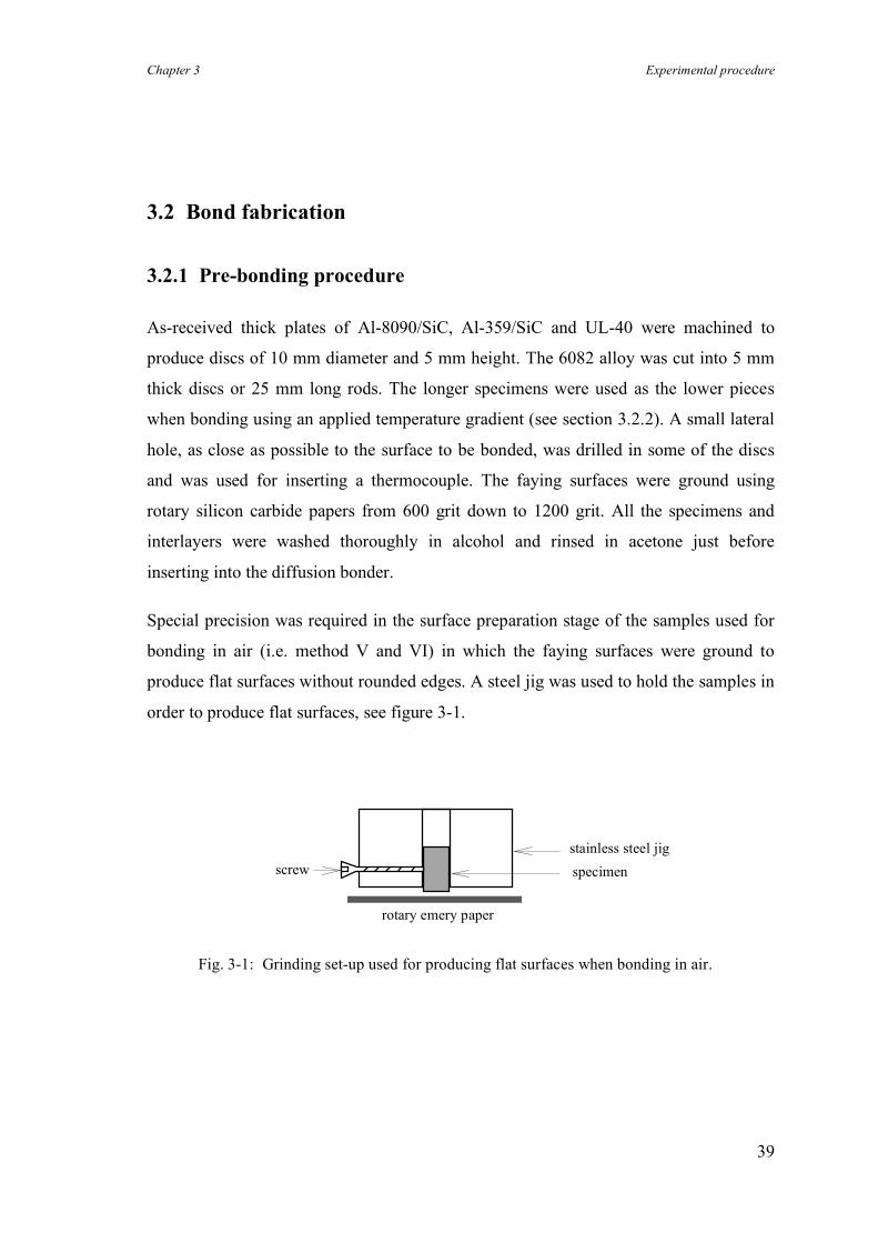
Chapter 3 Experimental procedure
39
3.2 Bond fabrication
3.2.1 Pre-bonding procedure
As-received thick plates of Al-8090/SiC, Al-359/SiC and UL-40 were machined to
produce discs of 10 mm diameter and 5 mm height. The 6082 alloy was cut into 5 mm
thick discs or 25 mm long rods. The longer specimens were used as the lower pieces
when bonding using an applied temperature gradient (see section 3.2.2). A small lateral
hole, as close as possible to the surface to be bonded, was drilled in some of the discs
and was used for inserting a thermocouple. The faying surfaces were ground using
rotary silicon carbide papers from 600 grit down to 1200 grit. All the specimens and
interlayers were washed thoroughly in alcohol and rinsed in acetone just before
inserting into the diffusion bonder.
Special precision was required in the surface preparation stage of the samples used for
bonding in air (i.e. method V and VI) in which the faying surfaces were ground to
produce flat surfaces without rounded edges. A steel jig was used to hold the samples in
order to produce flat surfaces, see figure 3-1.
stainless steel jig specimen screw
rotary emery paper
Fig. 3-1: Grinding set-up used for producing flat surfaces when bonding in air.
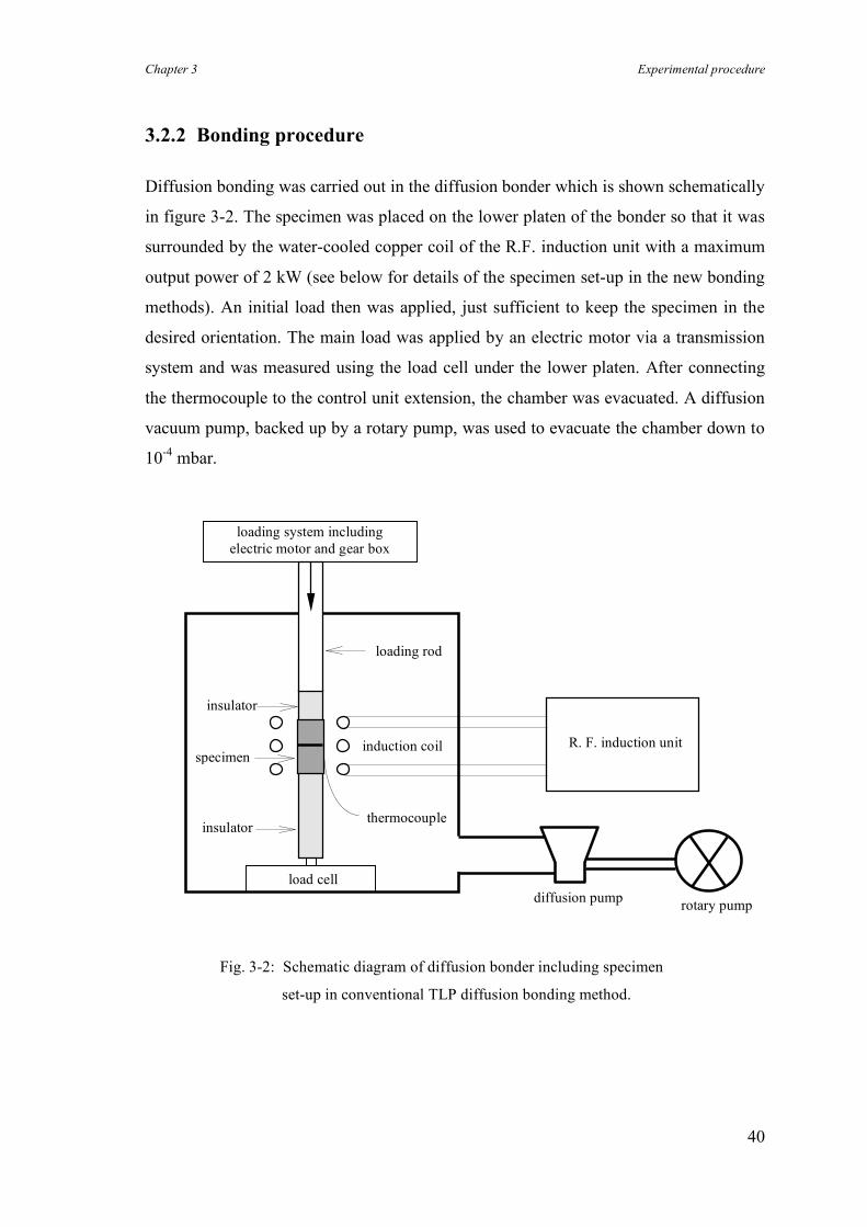
Chapter 3 Experimental procedure
40
3.2.2 Bonding procedure
Diffusion bonding was carried out in the diffusion bonder which is shown schematically
in figure 3-2. The specimen was placed on the lower platen of the bonder so that it was
surrounded by the water-cooled copper coil of the R.F. induction unit with a maximum
output power of 2 kW (see below for details of the specimen set-up in the new bonding
methods). An initial load then was applied, just sufficient to keep the specimen in the
desired orientation. The main load was applied by an electric motor via a transmission
system and was measured using the load cell under the lower platen. After connecting
the thermocouple to the control unit extension, the chamber was evacuated. A diffusion
vacuum pump, backed up by a rotary pump, was used to evacuate the chamber down to
10-4 mbar.
load cell
thermocouple
induction coil
insulator
specimen
loading rod
loading system including electric motor and gear box
diffusion pump rotary pump
R. F. induction unit
Fig. 3-2: Schematic diagram of diffusion bonder including specimen
set-up in conventional TLP diffusion bonding method.
insulator
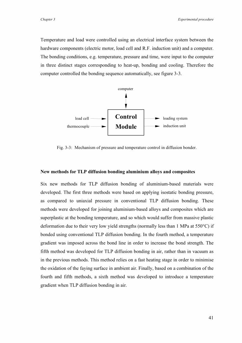
Chapter 3 Experimental procedure
41
Temperature and load were controlled using an electrical interface system between the
hardware components (electric motor, load cell and R.F. induction unit) and a computer.
The bonding conditions, e.g. temperature, pressure and time, were input to the computer
in three distinct stages corresponding to heat-up, bonding and cooling. Therefore the
computer controlled the bonding sequence automatically, see figure 3-3.
New methods for TLP diffusion bonding aluminium alloys and composites
Six new methods for TLP diffusion bonding of aluminium-based materials were
developed. The first three methods were based on applying isostatic bonding pressure,
as compared to uniaxial pressure in conventional TLP diffusion bonding. These
methods were developed for joining aluminium-based alloys and composites which are
superplastic at the bonding temperature, and so which would suffer from massive plastic
deformation due to their very low yield strengths (normally less than 1 MPa at 550°C) if
bonded using conventional TLP diffusion bonding. In the fourth method, a temperature
gradient was imposed across the bond line in order to increase the bond strength. The
fifth method was developed for TLP diffusion bonding in air, rather than in vacuum as
in the previous methods. This method relies on a fast heating stage in order to minimise
the oxidation of the faying surface in ambient air. Finally, based on a combination of the
fourth and fifth methods, a sixth method was developed to introduce a temperature
gradient when TLP diffusion bonding in air.
Control Module
load cell
thermocouple
computer
loading system
induction unit
Fig. 3-3: Mechanism of pressure and temperature control in diffusion bonder.
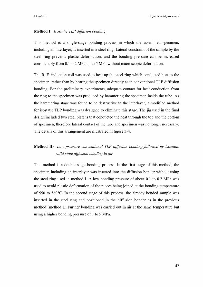
Chapter 3 Experimental procedure
42
Method I: Isostatic TLP diffusion bonding
This method is a single-stage bonding process in which the assembled specimen,
including an interlayer, is inserted in a steel ring. Lateral constraint of the sample by the
steel ring prevents plastic deformation, and the bonding pressure can be increased
considerably from 0.1-0.2 MPa up to 5 MPa without macroscopic deformation.
The R. F. induction coil was used to heat up the steel ring which conducted heat to the
specimen, rather than by heating the specimen directly as in conventional TLP diffusion
bonding. For the preliminary experiments, adequate contact for heat conduction from
the ring to the specimen was produced by hammering the specimen inside the tube. As
the hammering stage was found to be destructive to the interlayer, a modified method
for isostatic TLP bonding was designed to eliminate this stage. The jig used in the final
design included two steel platens that conducted the heat through the top and the bottom
of specimen, therefore lateral contact of the tube and specimen was no longer necessary.
The details of this arrangement are illustrated in figure 3-4.
Method II: Low pressure conventional TLP diffusion bonding followed by isostatic
solid-state diffusion bonding in air
This method is a double stage bonding process. In the first stage of this method, the
specimen including an interlayer was inserted into the diffusion bonder without using
the steel ring used in method I. A low bonding pressure of about 0.1 to 0.2 MPa was
used to avoid plastic deformation of the pieces being joined at the bonding temperature
of 550 to 560°C. In the second stage of this process, the already bonded sample was
inserted in the steel ring and positioned in the diffusion bonder as in the previous
method (method I). Further bonding was carried out in air at the same temperature but
using a higher bonding pressure of 1 to 5 MPa.
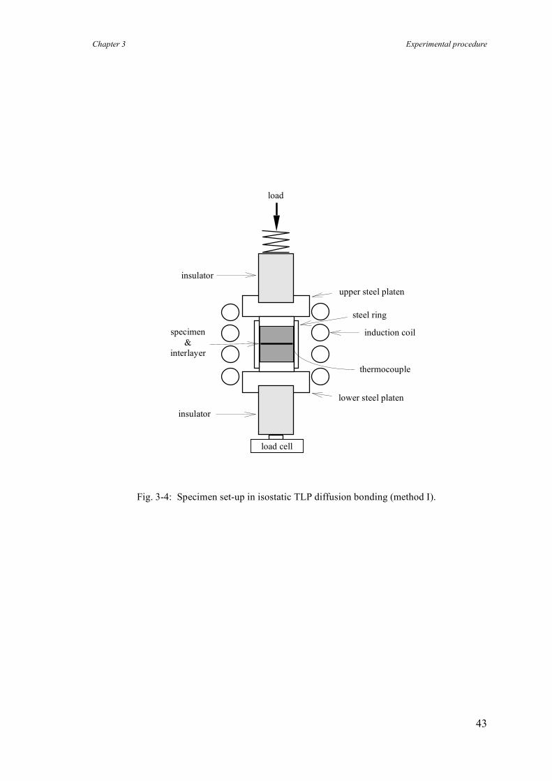
Chapter 3 Experimental procedure
43
Fig. 3-4: Specimen set-up in isostatic TLP diffusion bonding (method I).
induction coil
insulator
specimen &
interlayer thermocouple
upper steel platen
lower steel platen
steel ring
load cell
insulator
load
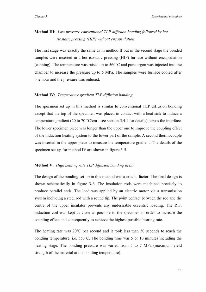
Chapter 3 Experimental procedure
44
Method III: Low pressure conventional TLP diffusion bonding followed by hot
isostatic pressing (HIP) without encapsulation
The first stage was exactly the same as in method II but in the second stage the bonded
samples were inserted in a hot isostatic pressing (HIP) furnace without encapsulation
(canning). The temperature was raised up to 560°C and pure argon was injected into the
chamber to increase the pressure up to 5 MPa. The samples were furnace cooled after
one hour and the pressure was reduced.
Method IV: Temperature gradient TLP diffusion bonding
The specimen set up in this method is similar to conventional TLP diffusion bonding
except that the top of the specimen was placed in contact with a heat sink to induce a
temperature gradient (20 to 70 °C/cm - see section 5.4.1 for details) across the interface.
The lower specimen piece was longer than the upper one to improve the coupling effect
of the induction heating system to the lower part of the sample. A second thermocouple
was inserted in the upper piece to measure the temperature gradient. The details of the
specimen set-up for method IV are shown in figure 3-5.
Method V: High heating rate TLP diffusion bonding in air
The design of the bonding set-up in this method was a crucial factor. The final design is
shown schematically in figure 3-6. The insulation rods were machined precisely to
produce parallel ends. The load was applied by an electric motor via a transmission
system including a steel rod with a round tip. The point contact between the rod and the
centre of the upper insulator prevents any undesirable eccentric loading. The R.F.
induction coil was kept as close as possible to the specimen in order to increase the
coupling effect and consequently to achieve the highest possible heating rate.
The heating rate was 20°C per second and it took less than 30 seconds to reach the
bonding temperature, i.e. 550°C. The bonding time was 5 or 10 minutes including the
heating stage. The bonding pressure was varied from 5 to 7 MPa (maximum yield
strength of the material at the bonding temperature).
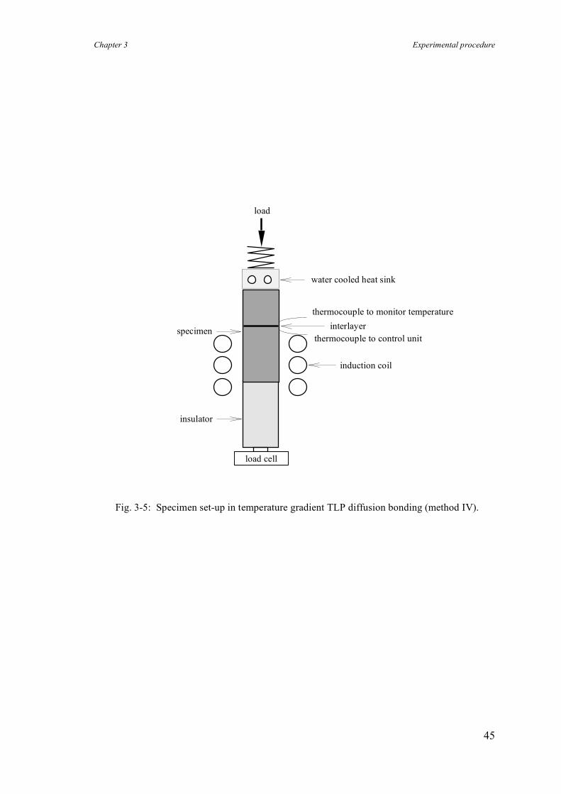
Chapter 3 Experimental procedure
45
Fig. 3-5: Specimen set-up in temperature gradient TLP diffusion bonding (method IV).
thermocouple to monitor temperature
induction coil
insulator
thermocouple to control unit
load
water cooled heat sink
specimen interlayer
load cell
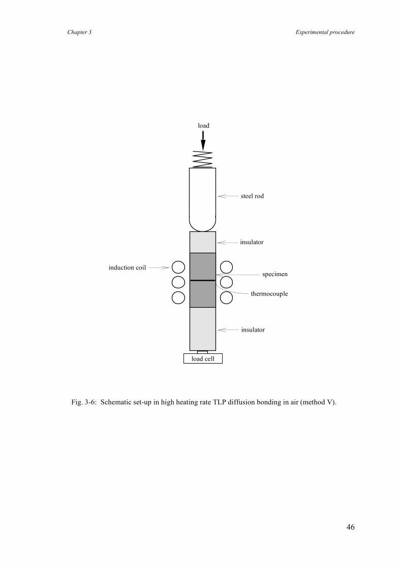
Chapter 3 Experimental procedure
46
Fig. 3-6: Schematic set-up in high heating rate TLP diffusion bonding in air (method V).
specimen induction coil
thermocouple
steel rod
insulator
insulator
load cell
load
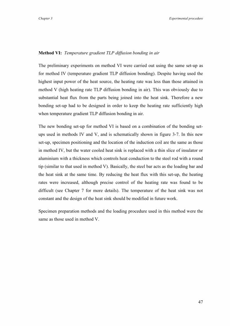
Chapter 3 Experimental procedure
47
Method VI: Temperature gradient TLP diffusion bonding in air
The preliminary experiments on method VI were carried out using the same set-up as
for method IV (temperature gradient TLP diffusion bonding). Despite having used the
highest input power of the heat source, the heating rate was less than those attained in
method V (high heating rate TLP diffusion bonding in air). This was obviously due to
substantial heat flux from the parts being joined into the heat sink. Therefore a new
bonding set-up had to be designed in order to keep the heating rate sufficiently high
when temperature gradient TLP diffusion bonding in air.
The new bonding set-up for method VI is based on a combination of the bonding set-
ups used in methods IV and V, and is schematically shown in figure 3-7. In this new
set-up, specimen positioning and the location of the induction coil are the same as those
in method IV, but the water cooled heat sink is replaced with a thin slice of insulator or
aluminium with a thickness which controls heat conduction to the steel rod with a round
tip (similar to that used in method V). Basically, the steel bar acts as the loading bar and
the heat sink at the same time. By reducing the heat flux with this set-up, the heating
rates were increased, although precise control of the heating rate was found to be
difficult (see Chapter 7 for more details). The temperature of the heat sink was not
constant and the design of the heat sink should be modified in future work.
Specimen preparation methods and the loading procedure used in this method were the
same as those used in method V.
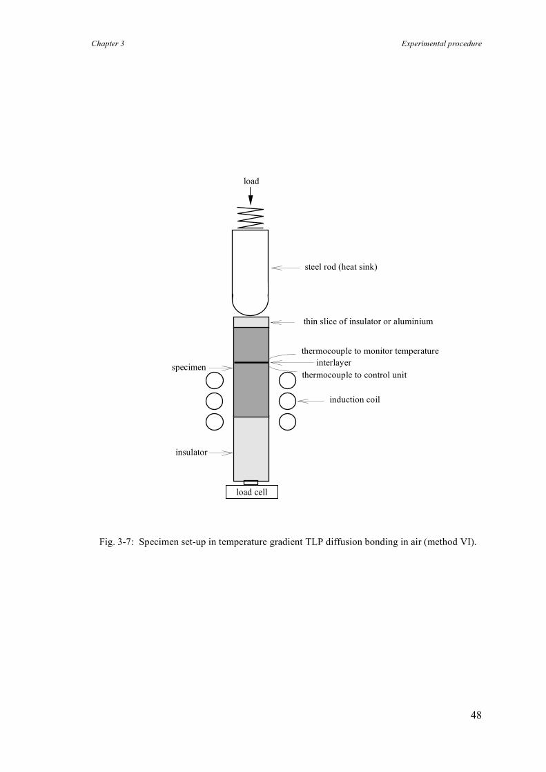
Chapter 3 Experimental procedure
48
Fig. 3-7: Specimen set-up in temperature gradient TLP diffusion bonding in air (method VI).
thermocouple to monitor temperature
induction coil
insulator
thermocouple to control unit
thin slice of insulator or aluminium
specimen interlayer
steel rod (heat sink)
load
load cell
Chapter 3 Experimental procedure
49
For the sake of simplicity, the main bonding parameters and the bonding method used in
each experiment will be abbreviated as shown in figure 3-8. As an example;
[ T 550:560 / P 0.2:5 / t 5:60 / M III ]
means that the first stage of method III was carried out at 550 °C under 0.2 MPa
pressure for a duration of 5 minutes and then bonding was followed by hot isostatic
pressing (hipping) at 560°C under 5 MPa pressure for 60 minutes.
3.2.3 Post bond heat treatment
Where appropriate, post-bond heat treatments were carried out to restore the mechanical
properties of the bonds. Bonded specimens and control samples of parent material were
soaked at 530-545°C for 20-30 minutes and quenched in water, followed by artificial
ageing at 165-185°C for 6-8 hours.
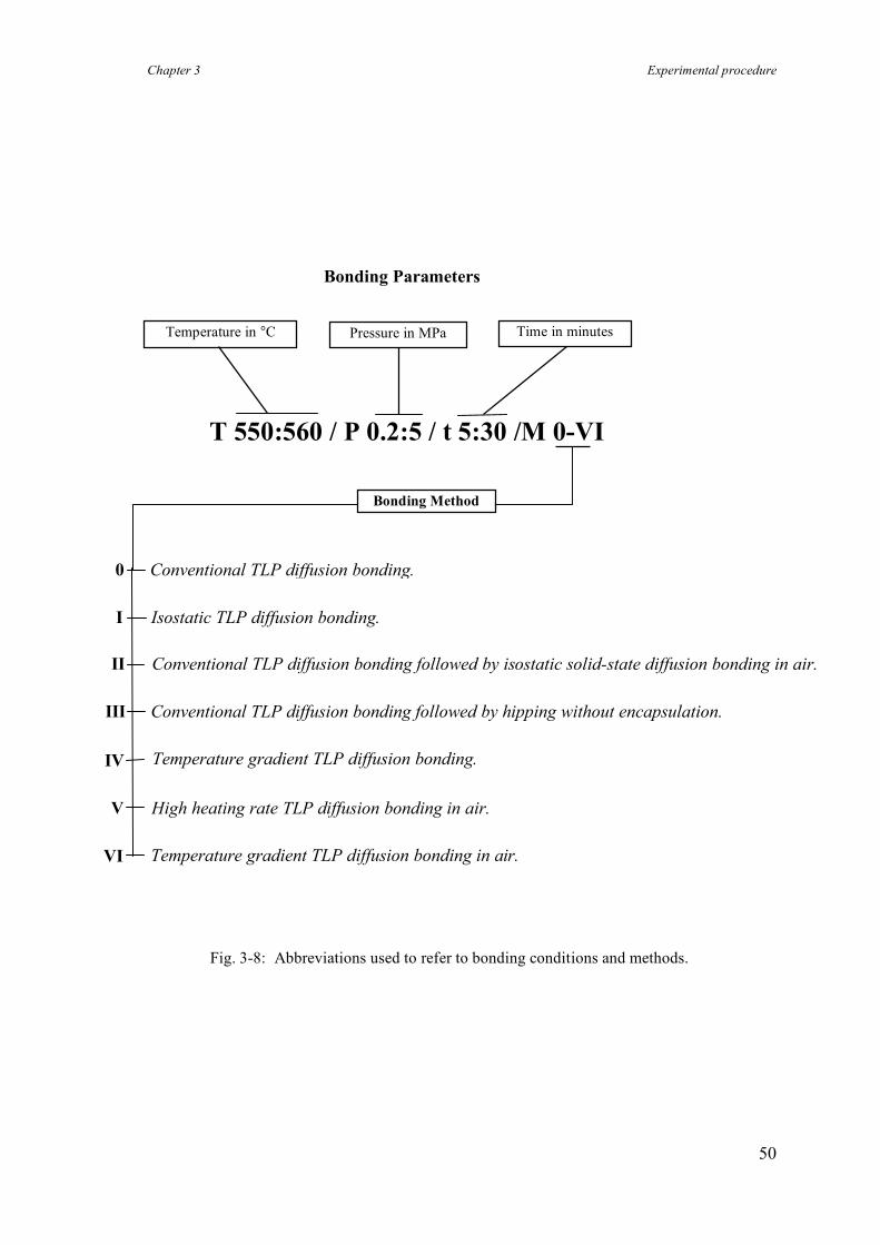
Chapter 3 Experimental procedure
50
Fig. 3-8: Abbreviations used to refer to bonding conditions and methods.
T 550:560 / P 0.2:5 / t 5:30 /M 0-VI
Conventional TLP diffusion bonding followed by hipping without encapsulation.
Bonding Parameters
Temperature in °C Pressure in MPa
Time in minutes
Conventional TLP diffusion bonding.
High heating rate TLP diffusion bonding in air.
Temperature gradient TLP diffusion bonding.
Isostatic TLP diffusion bonding.
Conventional TLP diffusion bonding followed by isostatic solid-state diffusion bonding in air.
Bonding Method
I
II
III
IV
V
0
Temperature gradient TLP diffusion bonding in air. VI
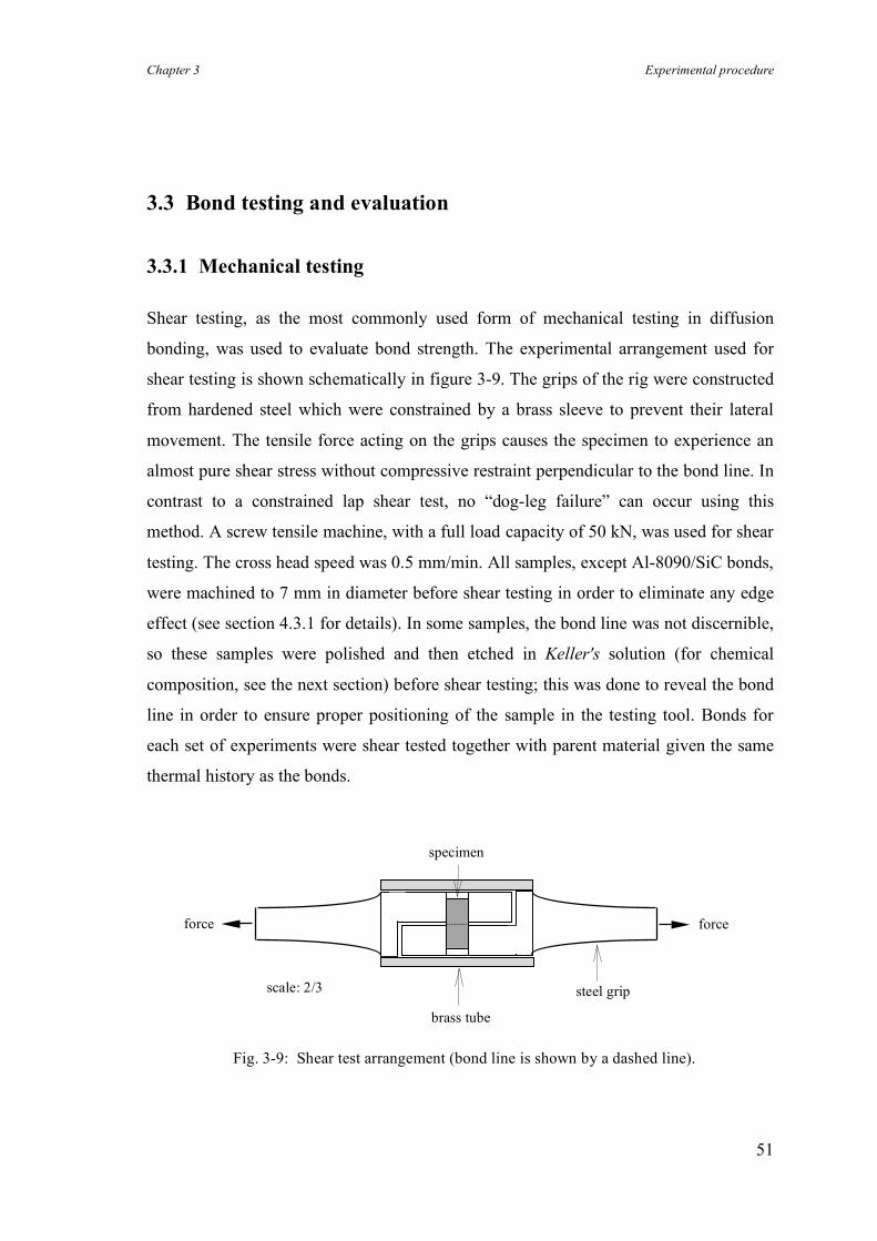
Chapter 3 Experimental procedure
51
3.3 Bond testing and evaluation
3.3.1 Mechanical testing
Shear testing, as the most commonly used form of mechanical testing in diffusion
bonding, was used to evaluate bond strength. The experimental arrangement used for
shear testing is shown schematically in figure 3-9. The grips of the rig were constructed
from hardened steel which were constrained by a brass sleeve to prevent their lateral
movement. The tensile force acting on the grips causes the specimen to experience an
almost pure shear stress without compressive restraint perpendicular to the bond line. In
contrast to a constrained lap shear test, no “dog-leg failure” can occur using this
method. A screw tensile machine, with a full load capacity of 50 kN, was used for shear
testing. The cross head speed was 0.5 mm/min. All samples, except Al-8090/SiC bonds,
were machined to 7 mm in diameter before shear testing in order to eliminate any edge
effect (see section 4.3.1 for details). In some samples, the bond line was not discernible,
so these samples were polished and then etched in Keller's solution (for chemical
composition, see the next section) before shear testing; this was done to reveal the bond
line in order to ensure proper positioning of the sample in the testing tool. Bonds for
each set of experiments were shear tested together with parent material given the same
thermal history as the bonds.
Fig. 3-9: Shear test arrangement (bond line is shown by a dashed line).
specimen
brass tube
steel grip
force force
scale: 2/3
Chapter 3 Experimental procedure
52
Hardness testing (micro-Vickers method with a load of 10 or 25 grams) was carried out
on some of the samples to measure hardness profiles across bond lines. All the samples
were ground using 1200 emery paper and polished to a ¼ micron diamond paste finish
before hardness testing.
3.3.2 Metallographic examination
Light microscopy
Specimens were cut perpendicular to the bond line by hand saw and were mounted in
bakelite. The mounted specimens were ground using silicon carbide papers from 600
grit down to 1200 grit followed by 6 and 1 µm diamond paste polishing. Keller's
reagent (2.5% NHO3, 1.5% HCl and 0.5% HF) was used as the etchant.
Scanning Electron Microscopy (SEM) and Energy Dispersive Spectroscopy (EDS)
SEM (JEOL 5800 LV) was used to study the shear fracture surfaces as it has a much
greater depth of field than light microscopy. The bond region was analysed chemically
by EDS. The analyses included the spot analysis of individual elements and the results
are reported in weight percentage.
Transmission Electron Microscopy (TEM) of Al/SiC composite
TEM can be used to investigate the oxide morphology and to characterise the
precipitates along a bond line. However, a detailed analysis of the bond line can be
achieved by TEM examination only if a reliable method for foil thinning is found.
Unfortunately, the use of an electrojet polishing technique was not satisfactory as the
solution corroded the matrix preferentially, without reacting with the reinforcement,
which eventually left a mesh-like structure! A combination of electropolishing and ion
beam machining also was not satisfactory, although this technique was used for the
thinning of diffusion bonds in un-reinforced aluminium alloys by Maddrell (1989).
Chapter 3 Experimental procedure
53
The most successful method for TEM sample preparation was based on a combination
of dimpling and ion bean machining. A high precision rotary cut-off machine was used
to cut a bonded sample into slices of 300 µm thickness and then each slice was mounted
on a flat base, using thermoplastic resin. These were then ground to produce 60 to 50
µm thickness foils. Three standard TEM discs were punched out of each foil, keeping
the bond line at the centre of each discs. The dimpling technique was used to thin the
area around the bond line. Finally ion beam machining was carried out until an orifice
was formed in the middle of the discs. The ion beam conditions were as follows:
• accelerating voltage: 5 kV
• beam current: 0.5 mA
• double ion guns at angle: 10° to 15°
• time: 1 to 3 hours
The TEM sampling technique, used in this work, is shown in figure 3-10. A Philips
400T transmission electron microscope was used for bright field, dark field and
diffraction contrast imaging.
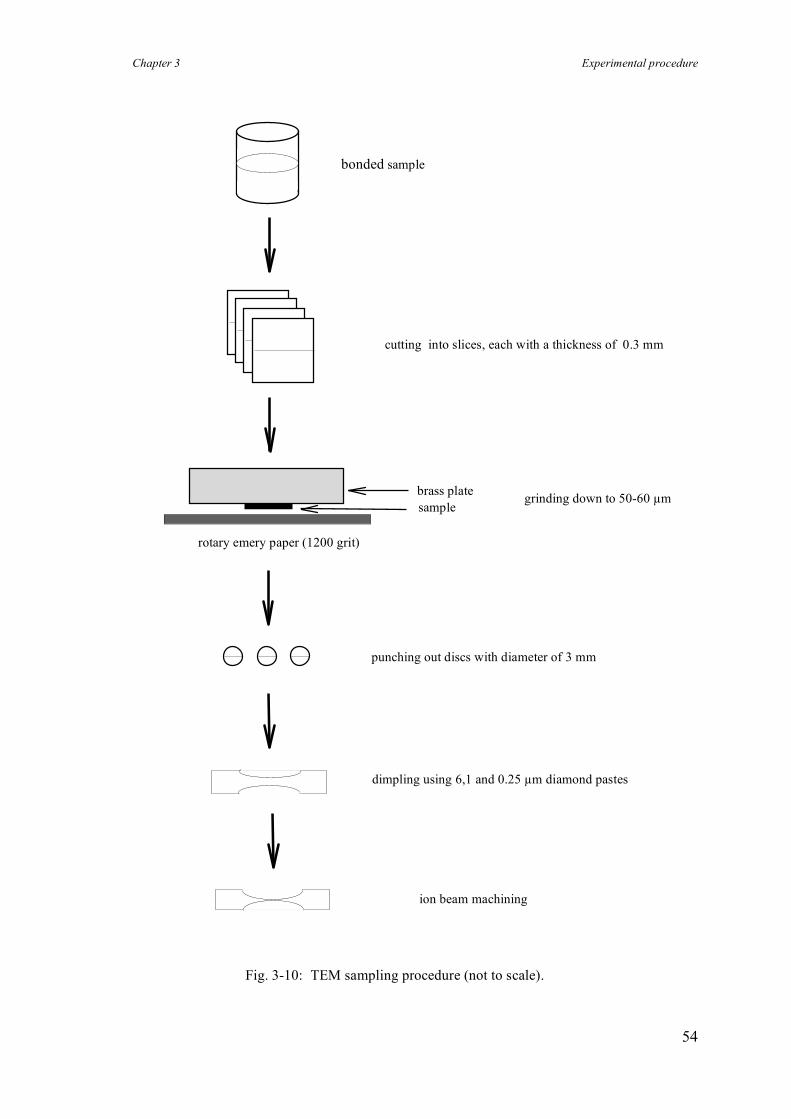
Chapter 3 Experimental procedure
54
bonded sample
cutting into slices, each with a thickness of 0.3 mm
punching out discs with diameter of 3 mm
ion beam machining
sample
rotary emery paper (1200 grit)
brass plate grinding down to 50-60 µm
Fig. 3-10: TEM sampling procedure (not to scale).
dimpling using 6,1 and 0.25 µm diamond pastes
Chapter 4 Methods I, II and III: TLP diffusion bonding aluminium-based composites
55
Chapter 4
4. Methods I, II and III: New methods for TLP diffusion
bonding aluminium-based composites
4.1 Introduction
The development of various metal matrix composites (MMCs) may be regarded as a
major advance in materials science and technology during the last two decades, Lloyd
(1994). Aluminium metal matrix composites (Al-MMCs) are of considerable interest
because of their superior mechanical properties compared to un-reinforced aluminium
alloys (especially their high stiffness, strength and wear resistance) which can provide
significant weight and performance benefits in transportation industries, Peel et al.
(1995). Following the recent development of low cost manufacturing processes, Al-
MMCs with particle reinforcement are now available commercially. However, despite
substantial improvements in the range and properties of such MMCs, their application,
which is potentially vast, has been somewhat restricted by the lack of reliable and
economic joining methods, Ellis et al. (1994).
Although fusion welding of un-reinforced aluminium alloys is well established, the high
temperature nature of the process normally causes unfavourable reactions between the
reinforcement and the matrix in Al-MMCs, see section 2.5 for details. Hence an
alternative approach is to use diffusion bonding which has proved successful for joining
aluminium-based alloys providing that the tenacious and chemically stable surface layer
of aluminium oxide is either removed or disrupted.
Chapter 4 Methods I, II and III: TLP diffusion bonding aluminium-based composites
56
In solid-state diffusion bonding, the brittle and continuous oxide layer can be broken up
by imposing substantial plastic deformation. Metal-to-metal contact is thus promoted
because of local disruption of the oxide film on both faying surfaces. In a recent
investigation of the solid-state diffusion bonding of Al-MMCs plastic deformation in
excess of 40% was required to produce satisfactory bonds, Urena et al. (1995). The
alternative approach of removing the oxide layer in vacuum by ion beam cleaning prior
to bonding is technically more complicated and this restricts its commercial application.
It is evident that it has not been possible to date to produce reproducible and high-
strength bonds in Al-MMCs using solid-state diffusion bonding, Ellis et al. (1994).
In transient liquid phase (TLP) diffusion bonding, the formation of a liquid phase at the
interface between the parts being joined can assist in the disruption of the oxide layer
and so promotes metallic bonding. Consequently, the required bonding pressure in this
process is quite low compared with solid-state diffusion bonding. The bonding
temperature is normally chosen to be slightly above the eutectic temperature in order to
ensure the eutectic reaction occurs, even though such a temperature may be relatively
high (i.e. close to the solidus of the parent material) when bonding aluminium-based
alloys and composites.
The use of copper interlayers has proved to be successful for joining some conventional
aluminium alloys, and bonds with shear strengths comparable to that of the parent
material have been reported, Dray (1985). However, there is a potential difficulty in
applying even the low pressure required during bonding since most Al-MMCs are very
soft at TLP diffusion bonding temperatures (i.e. 550 °C when using a copper interlayer)
and excessive plastic deformation can occur during the bonding process. Hence most of
the previous work has been either carried out on thin plates or has used a constant
deformation arrangement in order to avoid excessive distortion of the parts being joined.
In the latter case, the bonding pressure is transient (decreasing as the temperature
increases) and its variation depends not only on the size and shape of the sample, but
also on the heating rate, the initial pressure applied and the thickness of the interlayer.
Therefore, the results reported from such investigations tend to be valid only for the
particular arrangement and material used. In addition, the effect of varying bonding
pressure cannot be investigated readily using a method employing constant deformation.
Chapter 4 Methods I, II and III: TLP diffusion bonding aluminium-based composites
57
Three new methods for TLP diffusion bonding of aluminium MMCs have been
developed in this work. These methods are based on applying isostatic bonding pressure
(rather than conventional uniaxial compression) in order to improve bond strength and
also minimise plastic deformation of these materials in the bonding process.
Chapter 4 Methods I, II and III: TLP diffusion bonding aluminium-based composites
58
4.2 The aim of using isostatic pressure for TLP diffusion bonding
of aluminium MMCs
The aim in developing new methods for TLP diffusion bonding of Al-MMCs was to
overcome the following problems:
a) to improve bond strength since the highest bond strengths reported using TLP
diffusion bonding are much lower than the shear strength of the parent material;
b) to reduce the extent of plastic deformation when diffusion bonding aluminium-
based materials, since this would not be tolerated in a number of potential
applications.
c) to minimise the scatter in bond strength since high scatter has been a major problem
with diffusion bonding, degrading the reliability of the process.
The use of isostatic compression, in place of conventional uniaxial compression, has the
following advantages:
i) the possibility of applying a uniform and constant bonding pressure across the
interface which should improve bond strength;
ii) the ability to vary more extensively bonding parameters such as pressure,
temperature and time in order to optimise bonding conditions and hence bond
strengths;
iii) the virtual elimination of plastic deformation which under an isostatic stress-state is
both negligible and also almost independent of the applied pressure, temperature,
shape, and dimensional variations. This leads to the possibility of high precision
joining of intricate parts with minimal deformation.
The three new approaches for TLP diffusion bonding, all based on the application of
isostatic pressure, are summarised in figure 4-1. The first variant of TLP diffusion
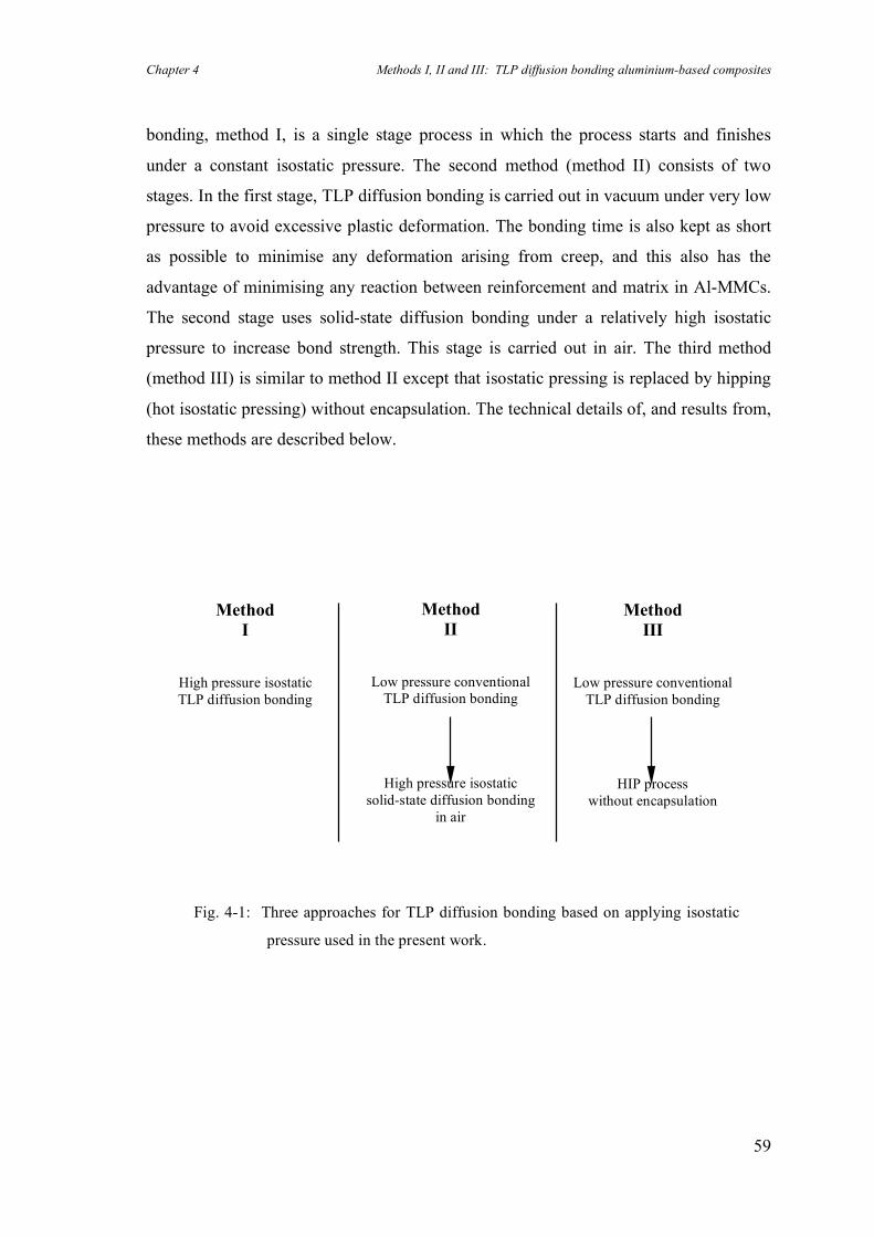
Chapter 4 Methods I, II and III: TLP diffusion bonding aluminium-based composites
59
bonding, method I, is a single stage process in which the process starts and finishes
under a constant isostatic pressure. The second method (method II) consists of two
stages. In the first stage, TLP diffusion bonding is carried out in vacuum under very low
pressure to avoid excessive plastic deformation. The bonding time is also kept as short
as possible to minimise any deformation arising from creep, and this also has the
advantage of minimising any reaction between reinforcement and matrix in Al-MMCs.
The second stage uses solid-state diffusion bonding under a relatively high isostatic
pressure to increase bond strength. This stage is carried out in air. The third method
(method III) is similar to method II except that isostatic pressing is replaced by hipping
(hot isostatic pressing) without encapsulation. The technical details of, and results from,
these methods are described below.
Fig. 4-1: Three approaches for TLP diffusion bonding based on applying isostatic
pressure used in the present work.
Method II
Low pressure conventional TLP diffusion bonding
High pressure isostatic solid-state diffusion bonding
in air
Method I
High pressure isostatic TLP diffusion bonding
Method III
Low pressure conventional TLP diffusion bonding
HIP process without encapsulation
Chapter 4 Methods I, II and III: TLP diffusion bonding aluminium-based composites
60
4.3 Results and discussion
About 110 bonding trials were carried out and the use of isostatic compression in
methods I and II resulted in a remarkable improvement in the bond strengths of Al-
8090/SiC and Al-359/SiC composites compared with those obtained using conventional
TLP diffusion bonding.
4.3.1 Methods I and II
• Mechanical properties
The shear test results for Al-8090/SiC bonds are summarised in figure 4-2 which
includes maximum, average and minimum shear strengths for each of the methods.
Note that at least three samples were produced and shear tested for each of the bonding
methods. The highest bond strength achieved, using a 3 µm thickness copper interlayer
and the bonding conditions of [T 560 / P 1 / t 60 / M I], was 221 MPa which is 85% of
the shear strength of the parent material given the same T6 heat treatment. The highest
bond strength obtained using method II and the same interlayer was estimated to be 219
MPa (84% of the shear strength of the parent material) – see below. These values are
the highest bond strengths reported for this composite to date. They also are higher than
the maximum achievable bond strength predicted in the model of Partridge & Dunford
(1991). In that model, the maximum bond shear strength of a TLP diffusion bonded
joint in Al-8090/SiC composite is predicted to be lower than 190 MPa. This
inconsistency between the predictions of the model and the experimental results of this
work is discussed in section 4.4. In comparison, the shear strengths of bonds, made
using conventional TLP diffusion bonding with bonding pressures of 0.1 to 0.2 MPa,
were very low (maximum 105 MPa), see figure 4-2. The use of higher bonding
pressures (above 0.2 MPa) for conventional TLP diffusion bonding was not possible
because of the associated massive plastic deformation of the material at the bonding
temperature (560 °C).
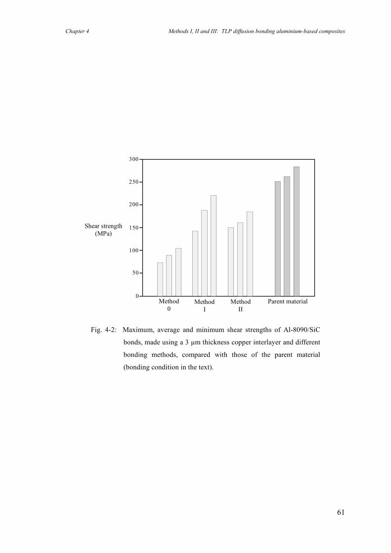
Chapter 4 Methods I, II and III: TLP diffusion bonding aluminium-based composites
61
Shear strength (MPa)
0
50
100
150
200
250
300
Parent material Method II
Method 0
Method I
Fig. 4-2: Maximum, average and minimum shear strengths of Al-8090/SiC
bonds, made using a 3 µm thickness copper interlayer and different
bonding methods, compared with those of the parent material
(bonding condition in the text).
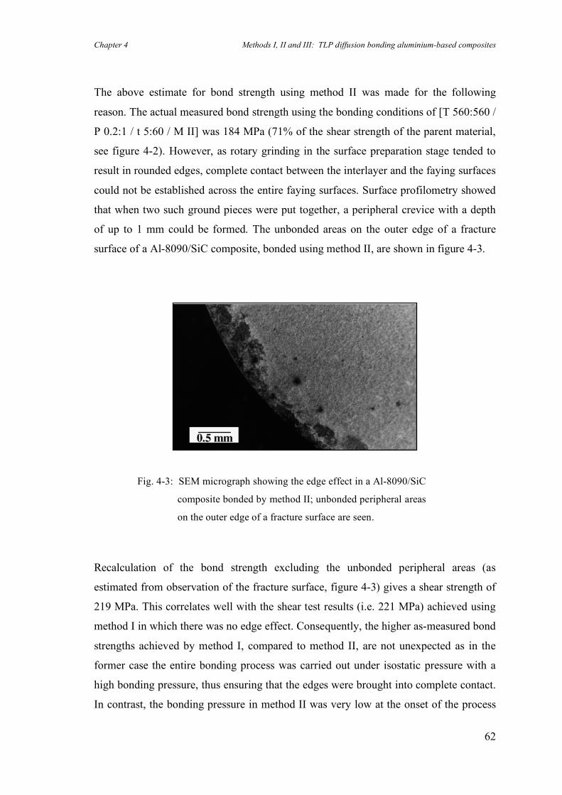
Chapter 4 Methods I, II and III: TLP diffusion bonding aluminium-based composites
62
The above estimate for bond strength using method II was made for the following
reason. The actual measured bond strength using the bonding conditions of [T 560:560 /
P 0.2:1 / t 5:60 / M II] was 184 MPa (71% of the shear strength of the parent material,
see figure 4-2). However, as rotary grinding in the surface preparation stage tended to
result in rounded edges, complete contact between the interlayer and the faying surfaces
could not be established across the entire faying surfaces. Surface profilometry showed
that when two such ground pieces were put together, a peripheral crevice with a depth
of up to 1 mm could be formed. The unbonded areas on the outer edge of a fracture
surface of a Al-8090/SiC composite, bonded using method II, are shown in figure 4-3.
Recalculation of the bond strength excluding the unbonded peripheral areas (as
estimated from observation of the fracture surface, figure 4-3) gives a shear strength of
219 MPa. This correlates well with the shear test results (i.e. 221 MPa) achieved using
method I in which there was no edge effect. Consequently, the higher as-measured bond
strengths achieved by method I, compared to method II, are not unexpected as in the
former case the entire bonding process was carried out under isostatic pressure with a
high bonding pressure, thus ensuring that the edges were brought into complete contact.
In contrast, the bonding pressure in method II was very low at the onset of the process
Fig. 4-3: SEM micrograph showing the edge effect in a Al-8090/SiC
composite bonded by method II; unbonded peripheral areas
on the outer edge of a fracture surface are seen.
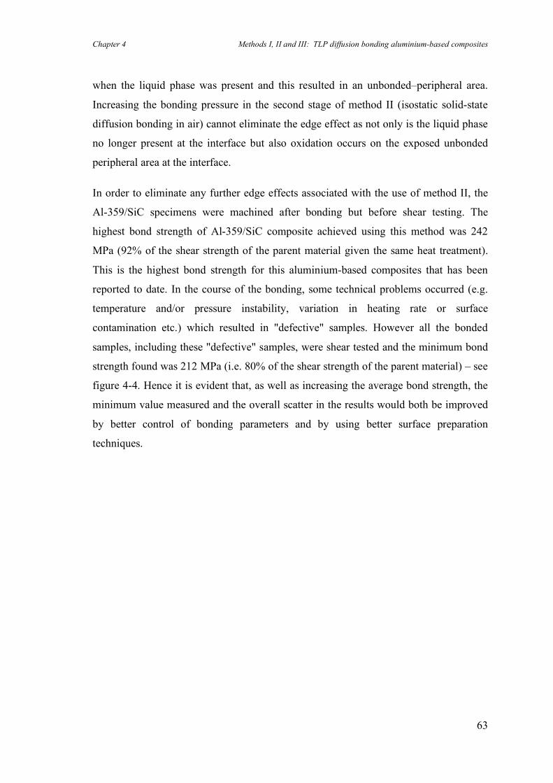
Chapter 4 Methods I, II and III: TLP diffusion bonding aluminium-based composites
63
when the liquid phase was present and this resulted in an unbonded–peripheral area.
Increasing the bonding pressure in the second stage of method II (isostatic solid-state
diffusion bonding in air) cannot eliminate the edge effect as not only is the liquid phase
no longer present at the interface but also oxidation occurs on the exposed unbonded
peripheral area at the interface.
In order to eliminate any further edge effects associated with the use of method II, the
Al-359/SiC specimens were machined after bonding but before shear testing. The
highest bond strength of Al-359/SiC composite achieved using this method was 242
MPa (92% of the shear strength of the parent material given the same heat treatment).
This is the highest bond strength for this aluminium-based composites that has been
reported to date. In the course of the bonding, some technical problems occurred (e.g.
temperature and/or pressure instability, variation in heating rate or surface
contamination etc.) which resulted in "defective" samples. However all the bonded
samples, including these "defective" samples, were shear tested and the minimum bond
strength found was 212 MPa (i.e. 80% of the shear strength of the parent material) – see
figure 4-4. Hence it is evident that, as well as increasing the average bond strength, the
minimum value measured and the overall scatter in the results would both be improved
by better control of bonding parameters and by using better surface preparation
techniques.
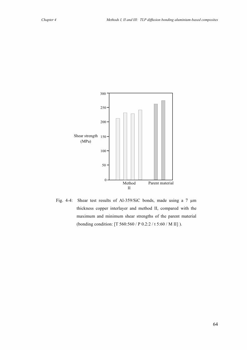
Chapter 4 Methods I, II and III: TLP diffusion bonding aluminium-based composites
64
0
50
100
150
200
250
300
Shear strength (MPa)
Parent material Method II
Fig. 4-4: Shear test results of Al-359/SiC bonds, made using a 7 µm
thickness copper interlayer and method II, compared with the
maximum and minimum shear strengths of the parent material
(bonding condition: [T 560:560 / P 0.2:2 / t 5:60 / M II] ).
Chapter 4 Methods I, II and III: TLP diffusion bonding aluminium-based composites
65
The effect of bonding time on the strength of Al-8090/SiC bonds was also investigated.
Although only a limited number of specimens were tested, it seems that increasing the
bonding time from 15 to 30 minutes under high isostatic pressure (5 MPa) does not
improve bond strength. The effect of bonding time when using lower bonding pressure
was not studied. The effects of bonding pressure, interlayer thickness and bonding time
on the bond strengths of the 8090 Al-SiC are summarised in figure 4-5.
a) bonding pressure; b) copper interlayer thickness; c) bonding time.
Figure 4-5: The effects of bonding parameters on the average shear strengths
of Al-8090/SiC bonds, made using method I, compared with the
maximum and minimum shear strengths of the parent material.
0
50
100
150
200
250
300
Shear strength (MPa)
1 - 5 MPa (a)
Parent material 3 - 7 µm (b)
15 - 30 mins (c)
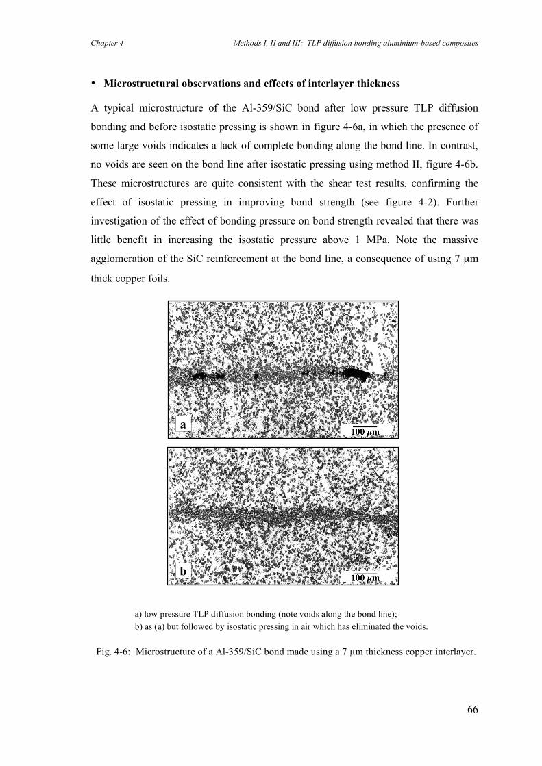
Chapter 4 Methods I, II and III: TLP diffusion bonding aluminium-based composites
66
• Microstructural observations and effects of interlayer thickness
A typical microstructure of the Al-359/SiC bond after low pressure TLP diffusion
bonding and before isostatic pressing is shown in figure 4-6a, in which the presence of
some large voids indicates a lack of complete bonding along the bond line. In contrast,
no voids are seen on the bond line after isostatic pressing using method II, figure 4-6b.
These microstructures are quite consistent with the shear test results, confirming the
effect of isostatic pressing in improving bond strength (see figure 4-2). Further
investigation of the effect of bonding pressure on bond strength revealed that there was
little benefit in increasing the isostatic pressure above 1 MPa. Note the massive
agglomeration of the SiC reinforcement at the bond line, a consequence of using 7 µm
thick copper foils.
a
b
a) low pressure TLP diffusion bonding (note voids along the bond line); b) as (a) but followed by isostatic pressing in air which has eliminated the voids.
Fig. 4-6: Microstructure of a Al-359/SiC bond made using a 7 µm thickness copper interlayer.
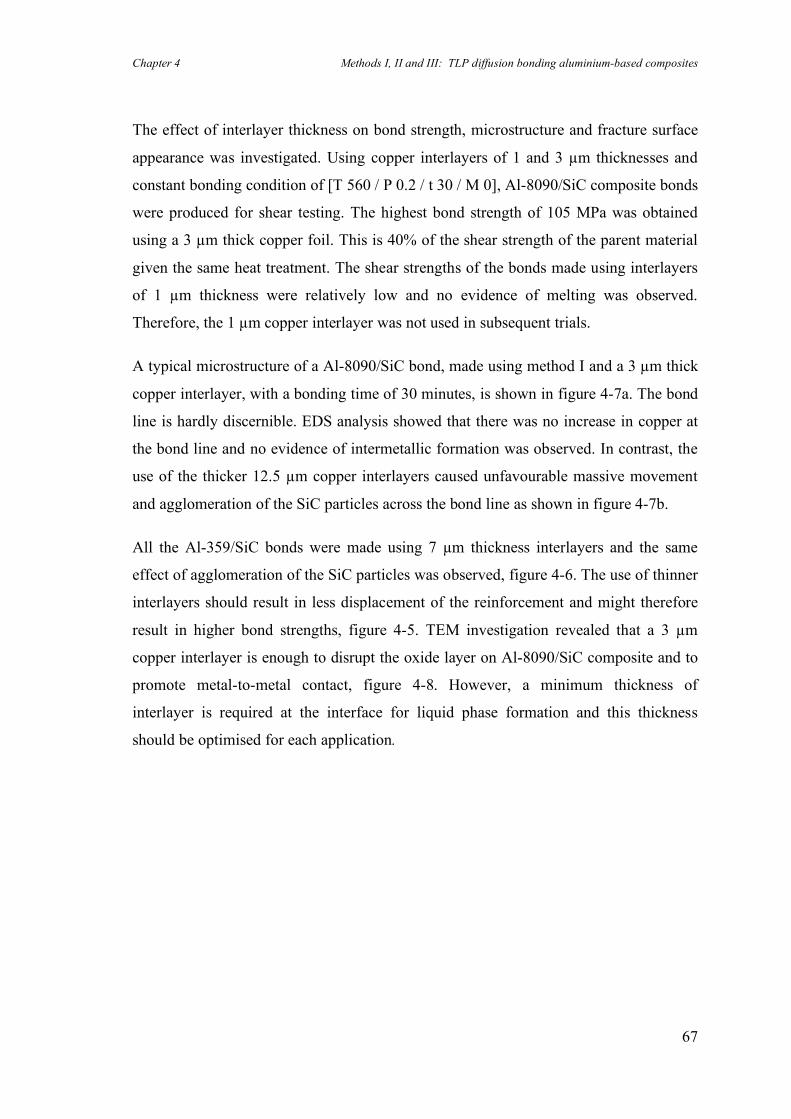
Chapter 4 Methods I, II and III: TLP diffusion bonding aluminium-based composites
67
The effect of interlayer thickness on bond strength, microstructure and fracture surface
appearance was investigated. Using copper interlayers of 1 and 3 µm thicknesses and
constant bonding condition of [T 560 / P 0.2 / t 30 / M 0], Al-8090/SiC composite bonds
were produced for shear testing. The highest bond strength of 105 MPa was obtained
using a 3 µm thick copper foil. This is 40% of the shear strength of the parent material
given the same heat treatment. The shear strengths of the bonds made using interlayers
of 1 µm thickness were relatively low and no evidence of melting was observed.
Therefore, the 1 µm copper interlayer was not used in subsequent trials.
A typical microstructure of a Al-8090/SiC bond, made using method I and a 3 µm thick
copper interlayer, with a bonding time of 30 minutes, is shown in figure 4-7a. The bond
line is hardly discernible. EDS analysis showed that there was no increase in copper at
the bond line and no evidence of intermetallic formation was observed. In contrast, the
use of the thicker 12.5 µm copper interlayers caused unfavourable massive movement
and agglomeration of the SiC particles across the bond line as shown in figure 4-7b.
All the Al-359/SiC bonds were made using 7 µm thickness interlayers and the same
effect of agglomeration of the SiC particles was observed, figure 4-6. The use of thinner
interlayers should result in less displacement of the reinforcement and might therefore
result in higher bond strengths, figure 4-5. TEM investigation revealed that a 3 µm
copper interlayer is enough to disrupt the oxide layer on Al-8090/SiC composite and to
promote metal-to-metal contact, figure 4-8. However, a minimum thickness of
interlayer is required at the interface for liquid phase formation and this thickness
should be optimised for each application.
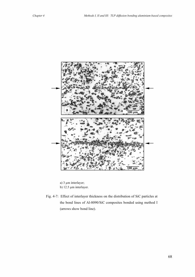
Chapter 4 Methods I, II and III: TLP diffusion bonding aluminium-based composites
68
a) 3 µm interlayer; b) 12.5 µm interlayer.
Fig. 4-7: Effect of interlayer thickness on the distribution of SiC particles at
the bond lines of Al-8090/SiC composites bonded using method I
(arrows show bond line).
a
b
Chapter 4 Methods I, II and III: TLP diffusion bonding aluminium-based composites
69
The fracture surfaces of the parent materials and of both bonded composites were
examined by SEM. In the case of Al-8090/SiC, the fracture surfaces of the parent
material and the bond with highest strength, made using a 3 µm copper interlayer,
looked similar implying that the fracture process was similar for both, figures 4-9a,b. In
contrast, in the case of Al-359/SiC, the corresponding fracture surfaces were not
identical when 7 µm copper interlayers were used, figures 4-9c,d. This is not surprising
as massive agglomeration of the reinforcement at the interface would be expected to
alter the fracture mode (compare figure 4-6 with figure 4-7a).
Figure 4-8: TEM micrograph of bond line (Al-8090/SiC) showing metal-
to-metal contact between the disrupted oxides (method I).
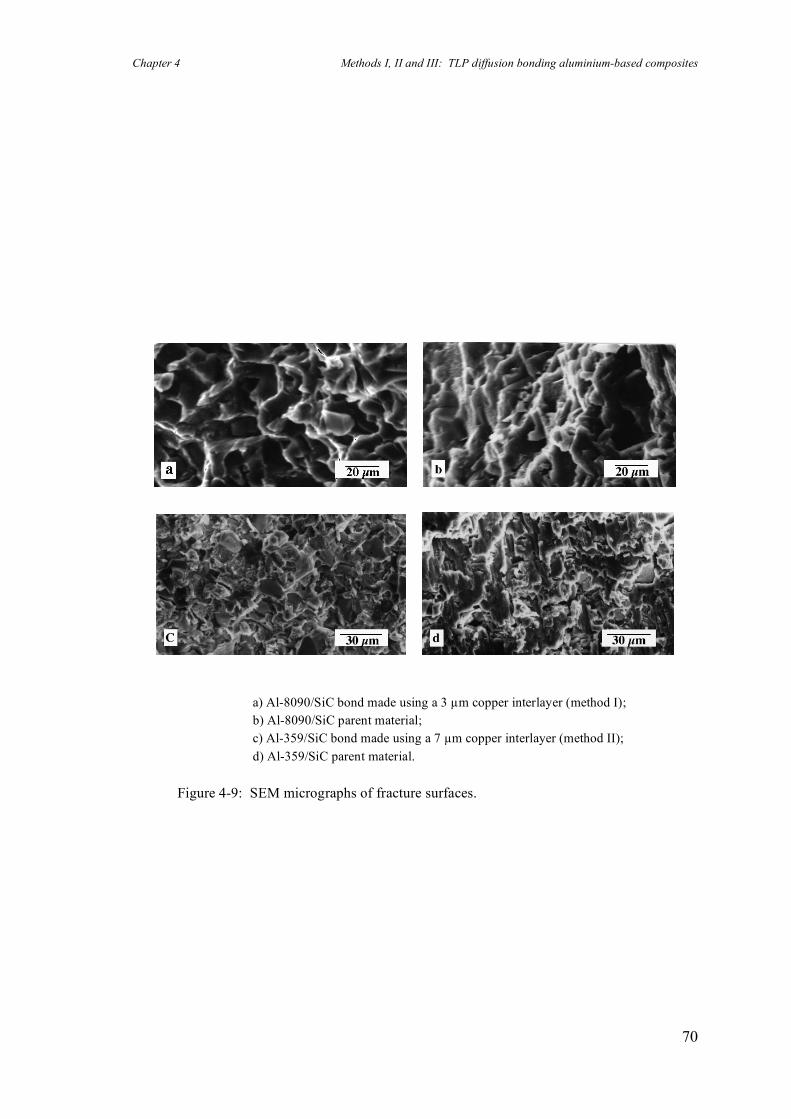
Chapter 4 Methods I, II and III: TLP diffusion bonding aluminium-based composites
70
a) Al-8090/SiC bond made using a 3 µm copper interlayer (method I); b) Al-8090/SiC parent material; c) Al-359/SiC bond made using a 7 µm copper interlayer (method II); d) Al-359/SiC parent material.
Figure 4-9: SEM micrographs of fracture surfaces.
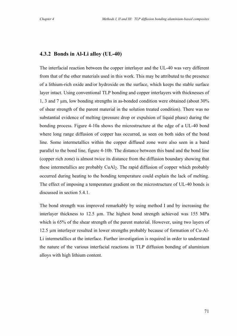
Chapter 4 Methods I, II and III: TLP diffusion bonding aluminium-based composites
71
4.3.2 Bonds in Al-Li alloy (UL-40)
The interfacial reaction between the copper interlayer and the UL-40 was very different
from that of the other materials used in this work. This may be attributed to the presence
of a lithium-rich oxide and/or hydroxide on the surface, which keeps the stable surface
layer intact. Using conventional TLP bonding and copper interlayers with thicknesses of
1, 3 and 7 µm, low bonding strengths in as-bonded condition were obtained (about 30%
of shear strength of the parent material in the solution treated condition). There was no
substantial evidence of melting (pressure drop or expulsion of liquid phase) during the
bonding process. Figure 4-10a shows the microstructure at the edge of a UL-40 bond
where long range diffusion of copper has occurred, as seen on both sides of the bond
line. Some intermetallics within the copper diffused zone were also seen in a band
parallel to the bond line, figure 4-10b. The distance between this band and the bond line
(copper rich zone) is almost twice its distance from the diffusion boundary showing that
these intermetallics are probably CuAl2. The rapid diffusion of copper which probably
occurred during heating to the bonding temperature could explain the lack of melting.
The effect of imposing a temperature gradient on the microstructure of UL-40 bonds is
discussed in section 5.4.1.
The bond strength was improved remarkably by using method I and by increasing the
interlayer thickness to 12.5 µm. The highest bond strength achieved was 155 MPa
which is 65% of the shear strength of the parent material. However, using two layers of
12.5 µm interlayer resulted in lower strengths probably because of formation of Cu-Al-
Li intermetallics at the interface. Further investigation is required in order to understand
the nature of the various interfacial reactions in TLP diffusion bonding of aluminium
alloys with high lithium content.
Chapter 4 Methods I, II and III: TLP diffusion bonding aluminium-based composites
72
a) outside edge of specimen (10 minutes at 550 °C, 7 µm copper interlayer); b) middle of specimen (4 minutes at 550 °C, 12.5 µm copper interlayer).
Fig. 4-10: Bond lines (UL-40) showing extent of copper diffusion zones and
precipitation of intermetallics (dark band) within the diffusion zones.
b
a
Chapter 4 Methods I, II and III: TLP diffusion bonding aluminium-based composites
73
4.3.3 Method III
Following the low pressure TLP diffusion bonding, in the first stage of method II, the
partially bonded sample has to be inserted in a steel jig to avoid plastic deformation
during subsequent high-pressure isostatic pressing . In contrast, in method III, the
second stage of the bonding process for the partially bonded sample is replaced by a
hipping process.
Simple finite element analysis, using Abacus and Patran packages, was carried out to
investigate and compare the plastic deformation around the interfacial voids during the
second stages of both methods II and III, and also in conventional solid-state bonding
(i.e. without any lateral constraint). Figure 4-11 shows schematically a bonded sample
with some voids at the interface. The results of the finite element analyses, when
bonding pure aluminium, are shown in figure 4-12. The analyses were carried out for a
quarter of the model in figure 4-11 as a consequence of symmetry.
In the case of solid-state bonding without lateral constraint, figure 4-12a, some void
shrinkage and massive lateral deformation has occurred. However the patterns of void
deformation in figures 4-12b and 4-12c are fairly similar, suggesting that the second
stage of the method II can be replaced be a hipping process. Theoretically, the stress
state and the field of strain in both cases should be exactly the same when the shear
strength of the material is negligible in comparison with the applied force, i.e. when the
material behaves like a liquid. The present difference in the patterns, 12b and 12c, is due
to the shear strength of pure aluminium at the bonding temperature which has been
considered in the model.
The importance of hipping used in method III is for two reasons. First, there is no need
to constrain the material and, therefore, parts with complicated shapes can be processed
without a loss of dimensional accuracy. Second, in contrast to conventional HIP
bonding, encapsulation is not necessary as the bond line is already sealed in the first
stage of the method and this should facilitate use of this approach.
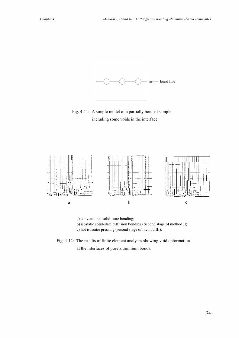
Chapter 4 Methods I, II and III: TLP diffusion bonding aluminium-based composites
74
Fig. 4-11: A simple model of a partially bonded sample
including some voids in the interface.
c
a b
bond line
a) conventional solid-state bonding; b) isostatic solid-state diffusion bonding (Second stage of method II); c) hot isostatic pressing (second stage of method III).
Fig. 4-12: The results of finite element analyses showing void deformation
at the interfaces of pure aluminium bonds.
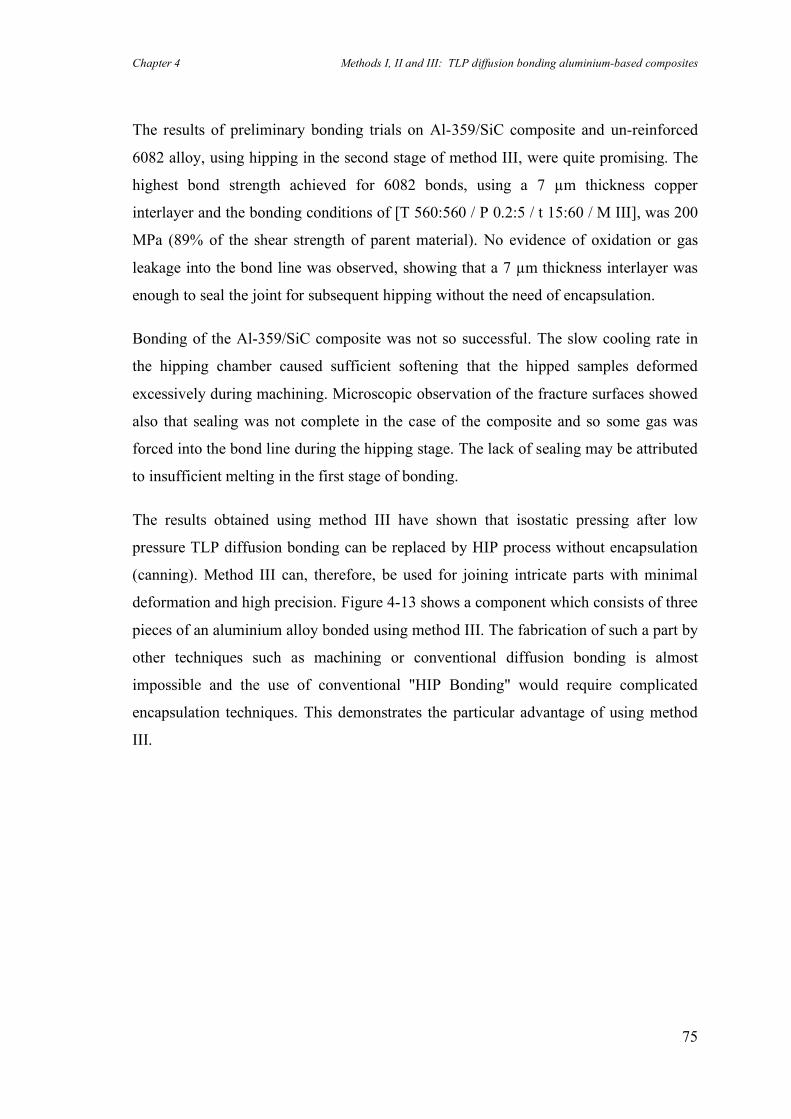
Chapter 4 Methods I, II and III: TLP diffusion bonding aluminium-based composites
75
The results of preliminary bonding trials on Al-359/SiC composite and un-reinforced
6082 alloy, using hipping in the second stage of method III, were quite promising. The
highest bond strength achieved for 6082 bonds, using a 7 µm thickness copper
interlayer and the bonding conditions of [T 560:560 / P 0.2:5 / t 15:60 / M III], was 200
MPa (89% of the shear strength of parent material). No evidence of oxidation or gas
leakage into the bond line was observed, showing that a 7 µm thickness interlayer was
enough to seal the joint for subsequent hipping without the need of encapsulation.
Bonding of the Al-359/SiC composite was not so successful. The slow cooling rate in
the hipping chamber caused sufficient softening that the hipped samples deformed
excessively during machining. Microscopic observation of the fracture surfaces showed
also that sealing was not complete in the case of the composite and so some gas was
forced into the bond line during the hipping stage. The lack of sealing may be attributed
to insufficient melting in the first stage of bonding.
The results obtained using method III have shown that isostatic pressing after low
pressure TLP diffusion bonding can be replaced by HIP process without encapsulation
(canning). Method III can, therefore, be used for joining intricate parts with minimal
deformation and high precision. Figure 4-13 shows a component which consists of three
pieces of an aluminium alloy bonded using method III. The fabrication of such a part by
other techniques such as machining or conventional diffusion bonding is almost
impossible and the use of conventional "HIP Bonding" would require complicated
encapsulation techniques. This demonstrates the particular advantage of using method
III.
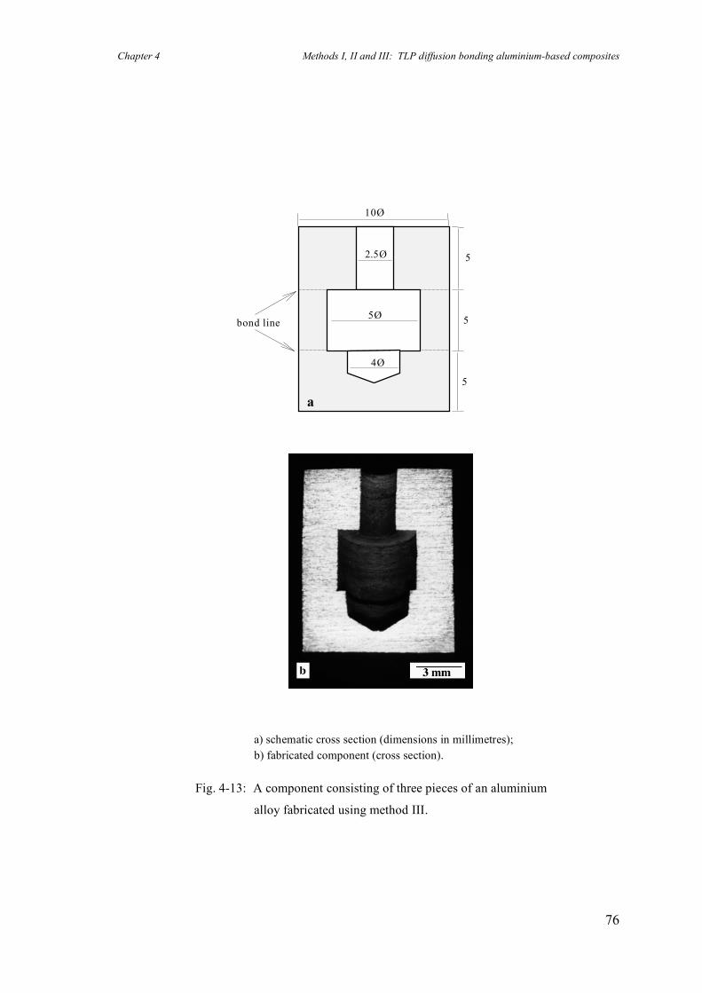
Chapter 4 Methods I, II and III: TLP diffusion bonding aluminium-based composites
76
bond line
5
5
5
10Ø
5Ø
2.5Ø
4Ø
a
a) schematic cross section (dimensions in millimetres); b) fabricated component (cross section).
Fig. 4-13: A component consisting of three pieces of an aluminium
alloy fabricated using method III.
Chapter 4 Methods I, II and III: TLP diffusion bonding aluminium-based composites
77
4.4 Case study: The role of reinforcement particles when
diffusion bonding Al-MMCs
Solid-state diffusion bonding
The bond line of an MMC-MMC joint generally consists of three different interfaces:
matrix/matrix, matrix/particle and particle/particle. Obviously, the area fractions of
these interfaces depend on the volume fraction and distribution of the reinforcement on
each of the two faying surfaces. Partridge & Dunford (1991) proposed a model which
shows that insertion of a matrix interlayer into a MMC-MMC bond interface may
increase or reduce the area fraction of the matrix/particle interface. According to this
model, the presence of either particle/particle or matrix/particle interfaces leads to a
lower shear strength of the bonded composite, compared to that of the bonded matrix
alloy (i.e. with 100% matrix/matrix interface). This is explained as follows: firstly,
almost no bond strength arises from a particle/particle interface and, secondly, the
strength of a matrix/particle bond is assumed to always be lower than that of a
matrix/matrix bond.
Experimental results of method I showed that joints in Al-809/SiC composite with shear
strengths as high as 221 MPa can be achieved (see section 4.3.1). This value is greater
than the upper bound value for the shear strength of a TLP diffusion-bonded Al-
8090/SiC composite as predicted by the model of Partridge & Dunford mentioned
above (i.e. 190 MPa). This inconsistency between the theoretical predicted value and
experimental result is considered below.
Basically the model assumes microscopically planar faying surfaces which form a flat
interface when the two surfaces are brought together during the diffusion bonding
process. However, SEM examination of a polished Al-8090/SiC composite revealed
that the reinforcement particles stick out of the polished surfaces, see figure 4-14. This
is simply due to the faster abrasion of the relatively soft aluminium matrix, compared
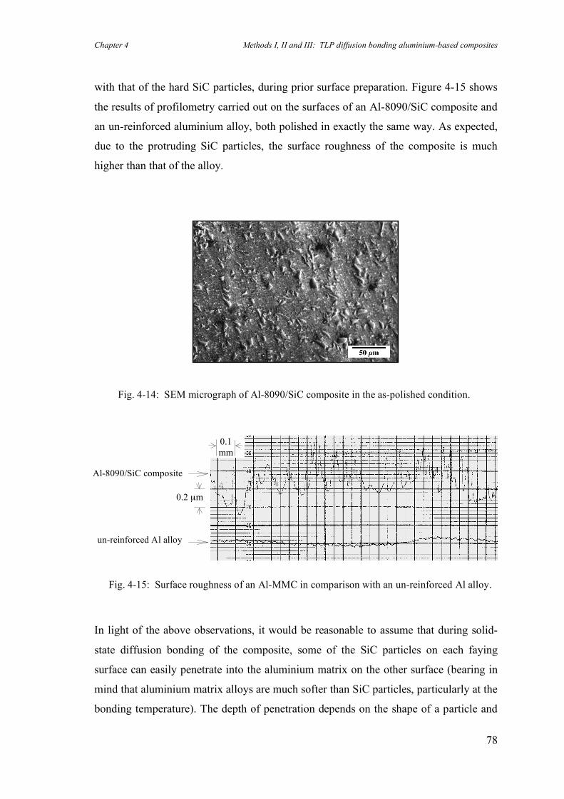
Chapter 4 Methods I, II and III: TLP diffusion bonding aluminium-based composites
78
with that of the hard SiC particles, during prior surface preparation. Figure 4-15 shows
the results of profilometry carried out on the surfaces of an Al-8090/SiC composite and
an un-reinforced aluminium alloy, both polished in exactly the same way. As expected,
due to the protruding SiC particles, the surface roughness of the composite is much
higher than that of the alloy.
In light of the above observations, it would be reasonable to assume that during solid-
state diffusion bonding of the composite, some of the SiC particles on each faying
surface can easily penetrate into the aluminium matrix on the other surface (bearing in
mind that aluminium matrix alloys are much softer than SiC particles, particularly at the
bonding temperature). The depth of penetration depends on the shape of a particle and
Al-8090/SiC composite
un-reinforced Al alloy
0.2 µm
0.1 mm
Fig. 4-15: Surface roughness of an Al-MMC in comparison with an un-reinforced Al alloy.
Fig. 4-14: SEM micrograph of Al-8090/SiC composite in the as-polished condition.
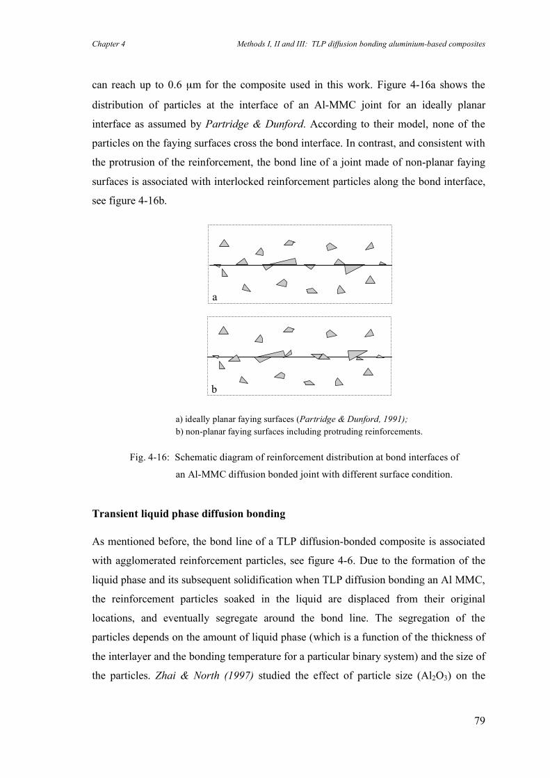
Chapter 4 Methods I, II and III: TLP diffusion bonding aluminium-based composites
79
can reach up to 0.6 µm for the composite used in this work. Figure 4-16a shows the
distribution of particles at the interface of an Al-MMC joint for an ideally planar
interface as assumed by Partridge & Dunford. According to their model, none of the
particles on the faying surfaces cross the bond interface. In contrast, and consistent with
the protrusion of the reinforcement, the bond line of a joint made of non-planar faying
surfaces is associated with interlocked reinforcement particles along the bond interface,
see figure 4-16b.
Transient liquid phase diffusion bonding
As mentioned before, the bond line of a TLP diffusion-bonded composite is associated
with agglomerated reinforcement particles, see figure 4-6. Due to the formation of the
liquid phase and its subsequent solidification when TLP diffusion bonding an Al MMC,
the reinforcement particles soaked in the liquid are displaced from their original
locations, and eventually segregate around the bond line. The segregation of the
particles depends on the amount of liquid phase (which is a function of the thickness of
the interlayer and the bonding temperature for a particular binary system) and the size of
the particles. Zhai & North (1997) studied the effect of particle size (Al2O3) on the
a) ideally planar faying surfaces (Partridge & Dunford, 1991); b) non-planar faying surfaces including protruding reinforcements.
Fig. 4-16: Schematic diagram of reinforcement distribution at bond interfaces of
an Al-MMC diffusion bonded joint with different surface condition.
a
b
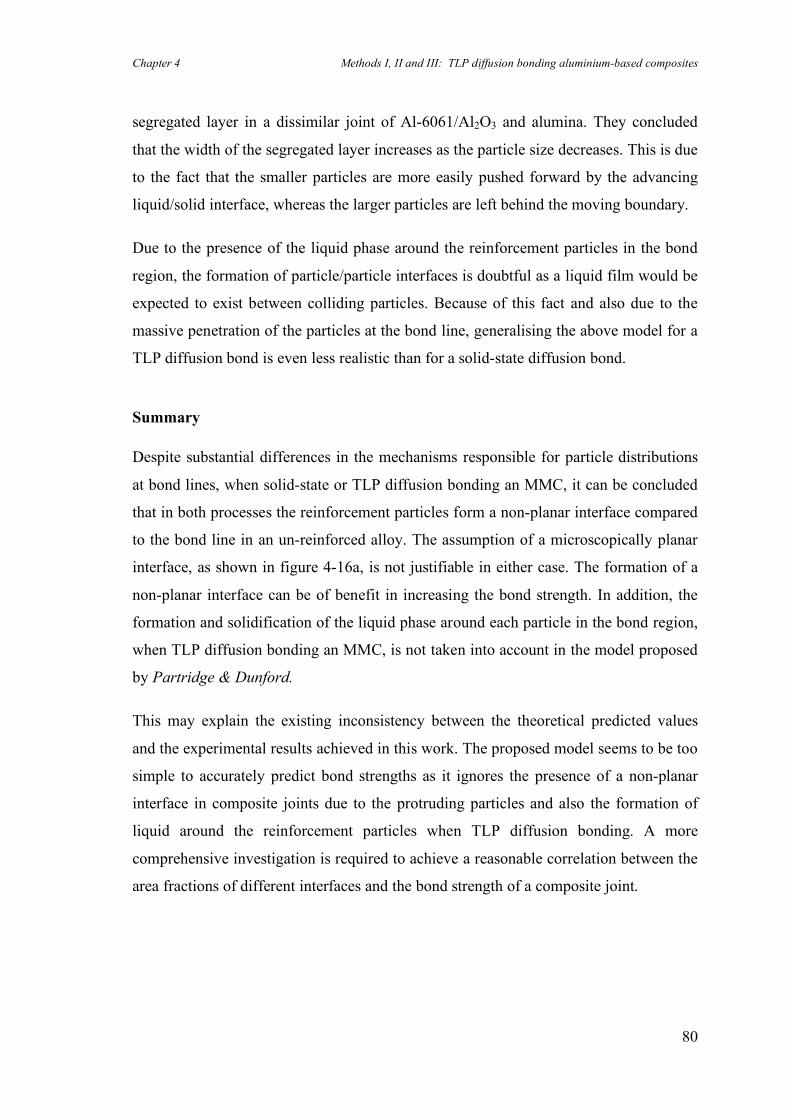
Chapter 4 Methods I, II and III: TLP diffusion bonding aluminium-based composites
80
segregated layer in a dissimilar joint of Al-6061/Al2O3 and alumina. They concluded
that the width of the segregated layer increases as the particle size decreases. This is due
to the fact that the smaller particles are more easily pushed forward by the advancing
liquid/solid interface, whereas the larger particles are left behind the moving boundary.
Due to the presence of the liquid phase around the reinforcement particles in the bond
region, the formation of particle/particle interfaces is doubtful as a liquid film would be
expected to exist between colliding particles. Because of this fact and also due to the
massive penetration of the particles at the bond line, generalising the above model for a
TLP diffusion bond is even less realistic than for a solid-state diffusion bond.
Summary
Despite substantial differences in the mechanisms responsible for particle distributions
at bond lines, when solid-state or TLP diffusion bonding an MMC, it can be concluded
that in both processes the reinforcement particles form a non-planar interface compared
to the bond line in an un-reinforced alloy. The assumption of a microscopically planar
interface, as shown in figure 4-16a, is not justifiable in either case. The formation of a
non-planar interface can be of benefit in increasing the bond strength. In addition, the
formation and solidification of the liquid phase around each particle in the bond region,
when TLP diffusion bonding an MMC, is not taken into account in the model proposed
by Partridge & Dunford.
This may explain the existing inconsistency between the theoretical predicted values
and the experimental results achieved in this work. The proposed model seems to be too
simple to accurately predict bond strengths as it ignores the presence of a non-planar
interface in composite joints due to the protruding particles and also the formation of
liquid around the reinforcement particles when TLP diffusion bonding. A more
comprehensive investigation is required to achieve a reasonable correlation between the
area fractions of different interfaces and the bond strength of a composite joint.
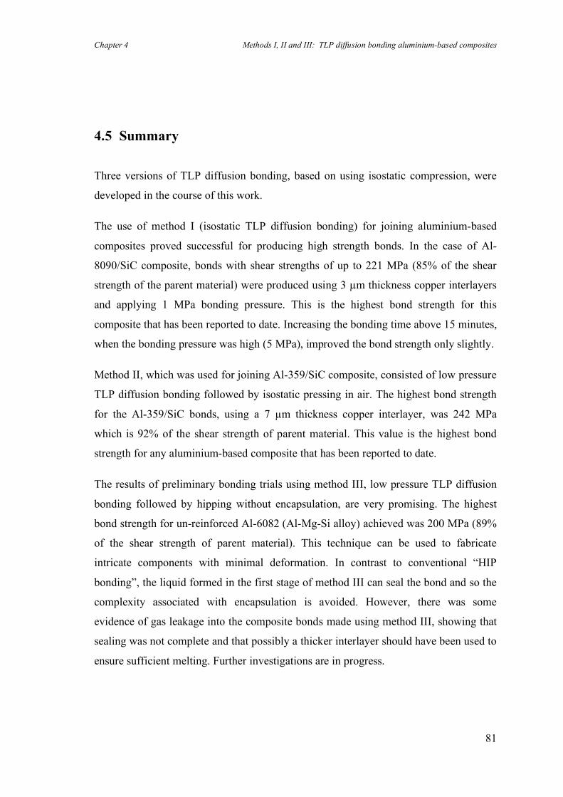
Chapter 4 Methods I, II and III: TLP diffusion bonding aluminium-based composites
81
4.5 Summary
Three versions of TLP diffusion bonding, based on using isostatic compression, were
developed in the course of this work.
The use of method I (isostatic TLP diffusion bonding) for joining aluminium-based
composites proved successful for producing high strength bonds. In the case of Al-
8090/SiC composite, bonds with shear strengths of up to 221 MPa (85% of the shear
strength of the parent material) were produced using 3 µm thickness copper interlayers
and applying 1 MPa bonding pressure. This is the highest bond strength for this
composite that has been reported to date. Increasing the bonding time above 15 minutes,
when the bonding pressure was high (5 MPa), improved the bond strength only slightly.
Method II, which was used for joining Al-359/SiC composite, consisted of low pressure
TLP diffusion bonding followed by isostatic pressing in air. The highest bond strength
for the Al-359/SiC bonds, using a 7 µm thickness copper interlayer, was 242 MPa
which is 92% of the shear strength of parent material. This value is the highest bond
strength for any aluminium-based composite that has been reported to date.
The results of preliminary bonding trials using method III, low pressure TLP diffusion
bonding followed by hipping without encapsulation, are very promising. The highest
bond strength for un-reinforced Al-6082 (Al-Mg-Si alloy) achieved was 200 MPa (89%
of the shear strength of parent material). This technique can be used to fabricate
intricate components with minimal deformation. In contrast to conventional “HIP
bonding”, the liquid formed in the first stage of method III can seal the bond and so the
complexity associated with encapsulation is avoided. However, there was some
evidence of gas leakage into the composite bonds made using method III, showing that
sealing was not complete and that possibly a thicker interlayer should have been used to
ensure sufficient melting. Further investigations are in progress.
Chapter 4 Methods I, II and III: TLP diffusion bonding aluminium-based composites
82
The aluminium-lithium alloy (UL-40) showed quite different bonding characteristics,
probably because of the high percentage of lithium (4 wt.%) which forms a very stable
surface layer. Copper interlayers with different thicknesses were tried and the maximum
bond strength achieved, using method I and an interlayer of 12.5 µm thickness, was 155
MPa (65% of the shear strength of parent material). Further improvement in bond
strength requires a comprehensive investigation into the nature of the interfacial
reactions during TLP diffusion bonding of this alloy.
The shear test results and examination of the microstructures showed that the thickness
of the interlayer has a key role in TLP diffusion bonding of Al-MMCs. Low bond
strengths resulted from the use of a 1 µm thickness copper interlayer. On the other hand,
the use of a thick interlayer (e.g. 12.5 µm) caused unfavourable agglomeration of the
reinforcement particles about the bond line. Thicknesses of between 3 and 7 µm
resulted in excellent strengths but the thickness of the interlayer should be optimised for
each alloy.
Chapter 5 Method IV: Temperature gradient TLP diffusion bonding
83
Chapter 5
5. Method IV: Temperature gradient TLP diffusion bonding
5.1 Introduction
Transient liquid phase (TLP) diffusion bonding is a promising method for joining
materials with stable oxide films. The presence of a liquid phase between two faying
surfaces can accelerate the joining process by disrupting any oxide and increasing the
diffusion rate at the interface. However, during isothermal solidification in TLP
diffusion bonding, the insoluble oxide particles and impurities, trapped within the liquid
phase, are pushed forward by the advancing solid/liquid boundaries. Eventually, these
particles agglomerate at the bond line and so can prevent metal-to-metal contact from
being fully established.
Accordingly, regardless of the type of diffusion bonding process, whether solid-state or
TLP, the bond lines are more or less planar and generally include impurities and
discontinuities which inhibit the formation of an ideal metallic bond. Therefore, the
strengths of such joints are expected to be somewhat less than the strengths of the
corresponding parent materials. In addition, the random distribution of oxide particles at
normally flat interfaces causes a wide scatter in the strengths of the bonds. In this
chapter a new TLP diffusion bonding method is described. This new method produces
joints with non-planar bond lines so leading to excellent reliability and shear strengths
as high as those of the parent material.
Chapter 5 Method IV: Temperature gradient TLP diffusion bonding
84
5.2 Theoretical aspects of temperature gradient TLP diffusion
bonding
Geologists have been studying the concept of frozen sea waters for many decades.
Whitman (1926) investigated certain characteristics of salt-water ice, including the
elimination of salt from floating sea ice during the warm season which had been
reported by Arctic travellers. He showed that liquid droplets of brine, entrapped in sea
ice, migrate from the colder part of the ice to the hotter part, provided the temperature of
the ice is not below the eutectic temperature. It was concluded that the salt diffuses out
of the ice as brine droplets due to the temperature gradient.
Three decades later, Pfann (1955) produced p-n semiconductive junctions by moving a
thin layer of molten Al-Si alloy through crystals of silicon and germanium, under a
temperature gradient. This process, called temperature gradient zone melting (TGZM),
includes a molten zone travelling up from the bottom to the top surface of a crystal,
where it solidifies by decreasing the temperature below the eutectic temperature. Pfann
also showed that imposing a temperature gradient during conventional zone refining
(i.e. when a local hot zone is moved along a bar) can be of benefit by increasing the
travel rate without increasing the concentration variation.
Conventional TLP diffusion bonding relies on the formation of a liquid phase at the
bond line during an isothermal bonding cycle, as a result of interdiffusion between an
interlayer and the base material. In contrast to Pfann’s method for producing p-n
junctions, this liquid phase eventually solidifies at constant temperature as a
consequence of continued diffusion of solute from the liquid phase into the adjacent
solid phase. Accordingly, the kinetics of a TLP process would, at first sight, appear to
depend mostly on the overall diffusivity of the solute in the solid parent material from
the liquid phase. Until now, this has been the generally accepted explanation for TLP
diffusion bonding. Thus, if the diffusion coefficient in the solid is assumed to be zero,
the solidification stage theoretically would never occur because the solid/liquid
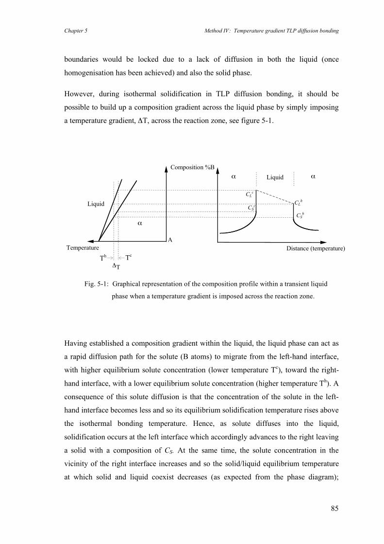
Chapter 5 Method IV: Temperature gradient TLP diffusion bonding
85
boundaries would be locked due to a lack of diffusion in both the liquid (once
homogenisation has been achieved) and also the solid phase.
However, during isothermal solidification in TLP diffusion bonding, it should be
possible to build up a composition gradient across the liquid phase by simply imposing
a temperature gradient, ΔT, across the reaction zone, see figure 5-1.
Distance (temperature)
!T
A
Temperature
Composition %B
CLc
CLh
CSc
CSh
"
Liquid
" "Liquid
Tc
Th
Having established a composition gradient within the liquid, the liquid phase can act as
a rapid diffusion path for the solute (B atoms) to migrate from the left-hand interface,
with higher equilibrium solute concentration (lower temperature Tc), toward the right-
hand interface, with a lower equilibrium solute concentration (higher temperature Th). A
consequence of this solute diffusion is that the concentration of the solute in the left-
hand interface becomes less and so its equilibrium solidification temperature rises above
the isothermal bonding temperature. Hence, as solute diffuses into the liquid,
solidification occurs at the left interface which accordingly advances to the right leaving
a solid with a composition of CS. At the same time, the solute concentration in the
vicinity of the right interface increases and so the solid/liquid equilibrium temperature
at which solid and liquid coexist decreases (as expected from the phase diagram);
Fig. 5-1: Graphical representation of the composition profile within a transient liquid
phase when a temperature gradient is imposed across the reaction zone.
Chapter 5 Method IV: Temperature gradient TLP diffusion bonding
86
consequently, melting occurs. The net result is that the right-hand interface retreats to
the right with the left-hand interface following, i.e. the interfaces move from the colder
side to the hotter side. As solute is included in the solid which forms at the left-hand
interface, the liquid will become steadily depleted in solute so that after a finite time all
the liquid will solidify.
This new method of temperature gradient TLP diffusion bonding, developed in this
work, has some similarities with conventional TLP diffusion bonding and temperature
gradient zone melting. However, it should be emphasised that, in this method,
solidification of the liquid phase occurs isothermally (in contrast to temperature gradient
zone melting) and, meantime, unlike conventional TLP diffusion bonding, the
isothermal solidification does not require diffusion of solute in the solid phase. An
important result from this new approach is that bonding times are likely to be
considerably shorter than those predicted using models which are based on solid-state
diffusion. An additional feature of imposing a temperature gradient during TLP
diffusion bonding is to produce a non-planar bond line, rather purifying the base
material or introducing solute atoms, as in zone refining. Accordingly, a new
experimental set-up and analytical model had to be developed in this work.
Chapter 5 Method IV: Temperature gradient TLP diffusion bonding
87
5.3 Numerical simulation of temperature gradient TLP diffusion
bonding
To date, only a few models of the kinetics of a moving boundary in transient liquid
phase processes have been proposed (see section 2.2). Using these analytical and
numerical models, a long completion time for isothermal solidification is predicted. In
the most recent work by Zhou et. al. (1995), the completion time for the diffusion
bonding of a nickel single crystal, using a Ni-19 at.% P interlayer, has been reported to
be 36 hours when bonding at a temperature of 1150°C. In polycrystalline materials,
relatively fast solute diffusion through the grain boundaries expedites the process and
consequently the bonding times are expected to be much shorter, e.g. about 20 hours
when bonding a nickel polycrystal under the same conditions as above. Nevertheless,
these are very long bonding times.
A simple mass balance calculation proves that completion of the TLP process under a
temperature gradient is possible even if the diffusivity of the solute in the solid phase is
assumed to be nil. This represents a condition for which existing conventional models
of TLP diffusion bonding would suggest that bonding could not be achieved. To verify
this idea, an explicit finite difference analysis of the new method, using Fick’s diffusion
equations and Mathematica software, was carried out in the current work. The first and
second derivatives of the concentration profiles, near to the moving boundaries, were
approximated by employing Crank’s (1975 & 1984) approach (see the appendix at the
end of this chapter). Assuming a temperature gradient across the liquid phase domain
and zero diffusivity in the solid phase, the new method was simulated. The graphical
results of the modelling, where isothermal solidification has started to occur at the left
hand interface, is shown in figure 5-2. The solid phase has a composition of Csc which
decreases as the interface moves further to the right.
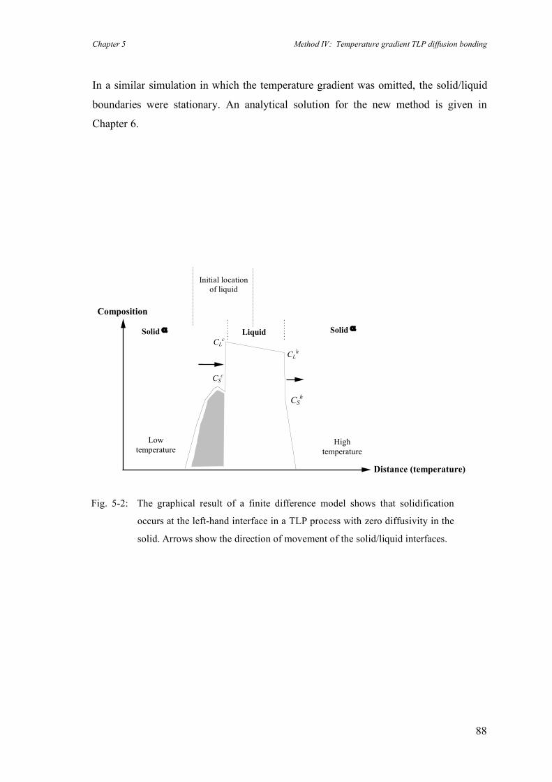
Chapter 5 Method IV: Temperature gradient TLP diffusion bonding
88
In a similar simulation in which the temperature gradient was omitted, the solid/liquid
boundaries were stationary. An analytical solution for the new method is given in
Chapter 6.
Distance (temperature)
Solid ! Solid !Liquid
CSc
CLc
CSh
CLh
High
temperature
Low
temperature
Composition
Fig. 5-2: The graphical result of a finite difference model shows that solidification
occurs at the left-hand interface in a TLP process with zero diffusivity in the
solid. Arrows show the direction of movement of the solid/liquid interfaces.
Initial location of liquid
Chapter 5 Method IV: Temperature gradient TLP diffusion bonding
89
5.4 Results and discussion
To study the effect of a temperature gradient on the microstructures and strengths of the
bonds, more than 10 different set-ups were designed and up to 150 bonding trials were
carried out. In addition to the effects of bonding temperature and magnitude of
temperature gradient, the effects of bonding pressure, bonding time were also studied in
order to optimise the bonding conditions. Most of the samples were evaluated by
metallographic examination, and then a few bonds, with appropriate microstructures,
were shear tested. A summary of the results is presented below.
5.4.1 Microstructure examination
The magnitude of the temperature gradient has a significant effect on the resulting
microstructure of the bond line. The higher the temperature gradient, the more the
interface departs from being planar, which is the normal form of the interface when
conventional TLP diffusion bonding is carried out. Having designed and optimised the
heat sink, the magnitude of temperature gradient was varied by changing the
temperature of the lower piece (see figure 3-5) from 540 to 560 °C (assuming that the
temperature of the upper piece, in contact with the heat sink, remained reasonably
constant). Bond lines with various geometries were produced by TLP diffusion bonding
aluminium alloys using copper interlayers and different temperature gradients in the
range of ~20 to ~70 °C/cm. Figure 5-3 shows schematically the relationship between the
magnitude of the temperature gradient and the resulting bond line morphology.
Imposing a minor temperature gradient changes the planar interface into a sinusoidal
structure. A further increase in the temperature gradient leads to cellular and eventually
fully dendritic growth across the bond line.
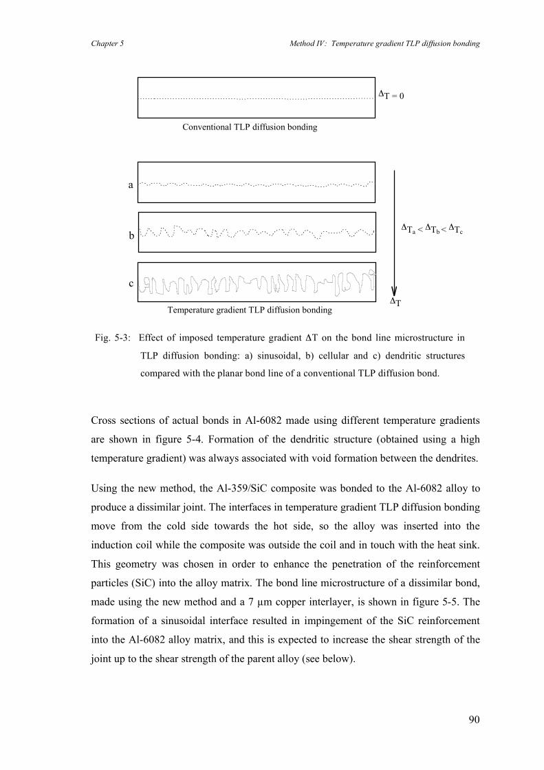
Chapter 5 Method IV: Temperature gradient TLP diffusion bonding
90
!T = 0
Conventional TLP diffusion bonding
Temperature gradient TLP diffusion bonding!T
a
b
c
!Ta < !Tb < !Tc
Cross sections of actual bonds in Al-6082 made using different temperature gradients
are shown in figure 5-4. Formation of the dendritic structure (obtained using a high
temperature gradient) was always associated with void formation between the dendrites.
Using the new method, the Al-359/SiC composite was bonded to the Al-6082 alloy to
produce a dissimilar joint. The interfaces in temperature gradient TLP diffusion bonding
move from the cold side towards the hot side, so the alloy was inserted into the
induction coil while the composite was outside the coil and in touch with the heat sink.
This geometry was chosen in order to enhance the penetration of the reinforcement
particles (SiC) into the alloy matrix. The bond line microstructure of a dissimilar bond,
made using the new method and a 7 µm copper interlayer, is shown in figure 5-5. The
formation of a sinusoidal interface resulted in impingement of the SiC reinforcement
into the Al-6082 alloy matrix, and this is expected to increase the shear strength of the
joint up to the shear strength of the parent alloy (see below).
Fig. 5-3: Effect of imposed temperature gradient ΔT on the bond line microstructure in
TLP diffusion bonding: a) sinusoidal, b) cellular and c) dendritic structures
compared with the planar bond line of a conventional TLP diffusion bond.
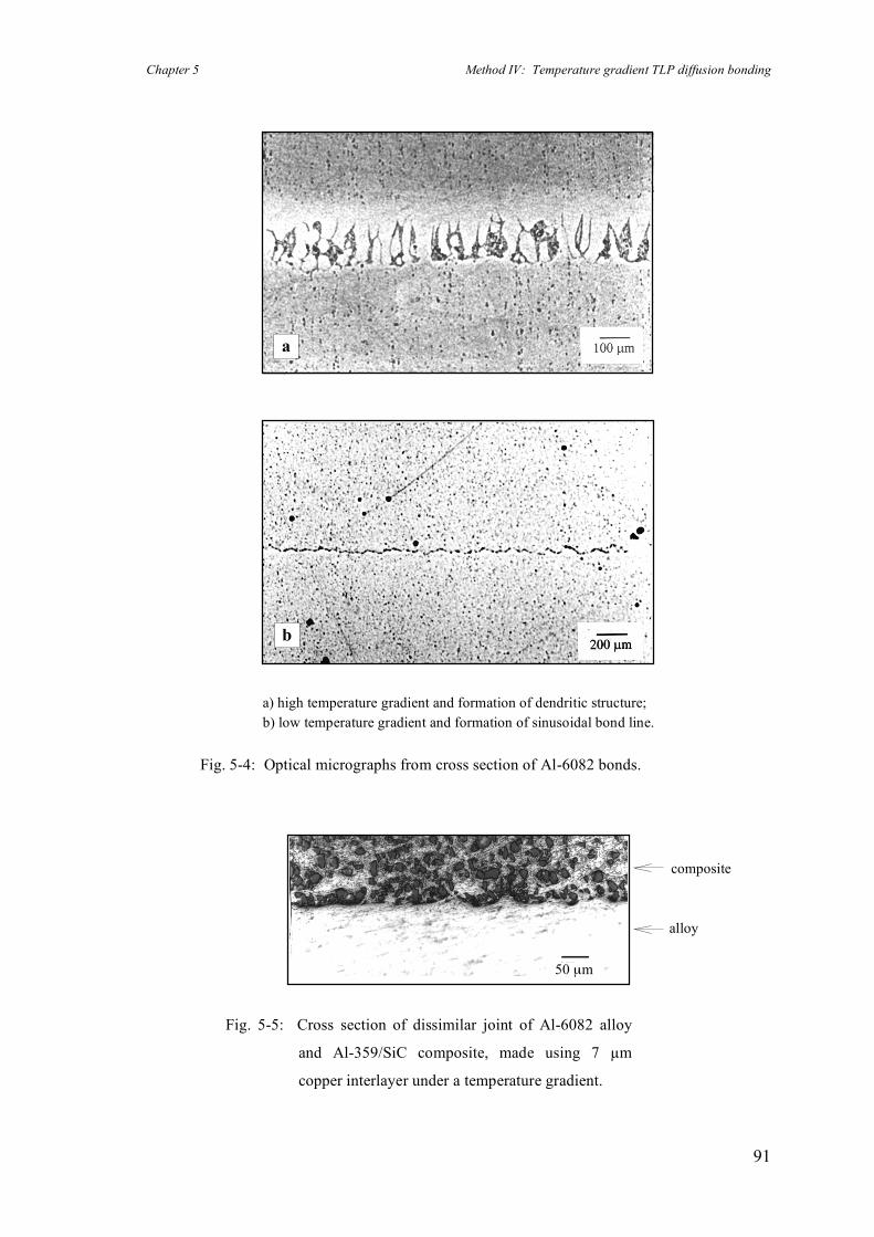
Chapter 5 Method IV: Temperature gradient TLP diffusion bonding
91
a) high temperature gradient and formation of dendritic structure; b) low temperature gradient and formation of sinusoidal bond line.
Fig. 5-4: Optical micrographs from cross section of Al-6082 bonds.
a
b
Fig. 5-5: Cross section of dissimilar joint of Al-6082 alloy
and Al-359/SiC composite, made using 7 µm
copper interlayer under a temperature gradient.
50 µm
composite
alloy
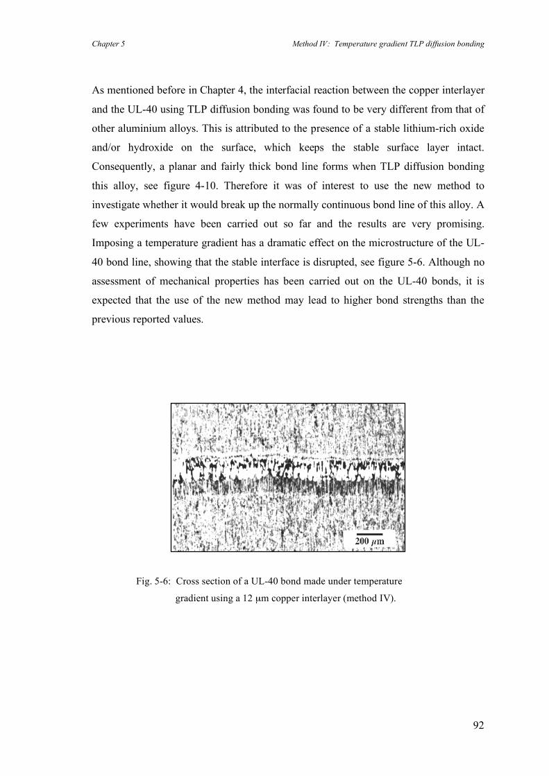
Chapter 5 Method IV: Temperature gradient TLP diffusion bonding
92
As mentioned before in Chapter 4, the interfacial reaction between the copper interlayer
and the UL-40 using TLP diffusion bonding was found to be very different from that of
other aluminium alloys. This is attributed to the presence of a stable lithium-rich oxide
and/or hydroxide on the surface, which keeps the stable surface layer intact.
Consequently, a planar and fairly thick bond line forms when TLP diffusion bonding
this alloy, see figure 4-10. Therefore it was of interest to use the new method to
investigate whether it would break up the normally continuous bond line of this alloy. A
few experiments have been carried out so far and the results are very promising.
Imposing a temperature gradient has a dramatic effect on the microstructure of the UL-
40 bond line, showing that the stable interface is disrupted, see figure 5-6. Although no
assessment of mechanical properties has been carried out on the UL-40 bonds, it is
expected that the use of the new method may lead to higher bond strengths than the
previous reported values.
Fig. 5-6: Cross section of a UL-40 bond made under temperature
gradient using a 12 µm copper interlayer (method IV).
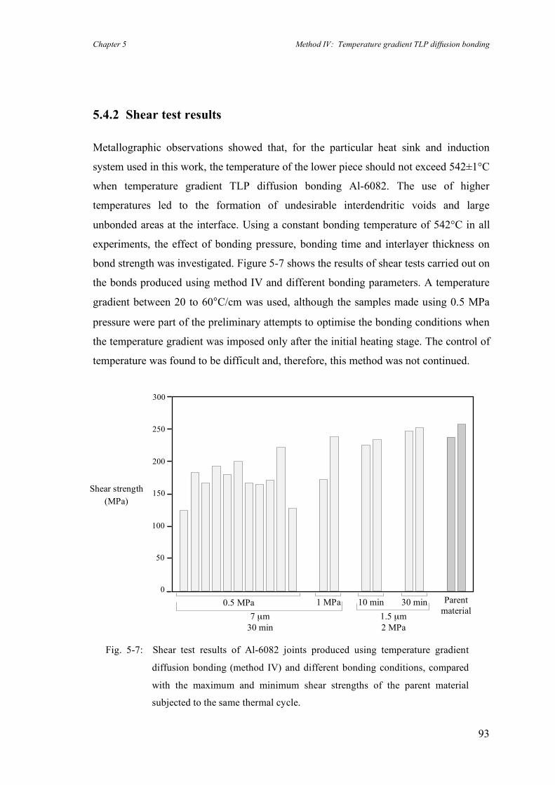
Chapter 5 Method IV: Temperature gradient TLP diffusion bonding
93
5.4.2 Shear test results
Metallographic observations showed that, for the particular heat sink and induction
system used in this work, the temperature of the lower piece should not exceed 542±1°C
when temperature gradient TLP diffusion bonding Al-6082. The use of higher
temperatures led to the formation of undesirable interdendritic voids and large
unbonded areas at the interface. Using a constant bonding temperature of 542°C in all
experiments, the effect of bonding pressure, bonding time and interlayer thickness on
bond strength was investigated. Figure 5-7 shows the results of shear tests carried out on
the bonds produced using method IV and different bonding parameters. A temperature
gradient between 20 to 60°C/cm was used, although the samples made using 0.5 MPa
pressure were part of the preliminary attempts to optimise the bonding conditions when
the temperature gradient was imposed only after the initial heating stage. The control of
temperature was found to be difficult and, therefore, this method was not continued.
Fig. 5-7: Shear test results of Al-6082 joints produced using temperature gradient
diffusion bonding (method IV) and different bonding conditions, compared
with the maximum and minimum shear strengths of the parent material
subjected to the same thermal cycle.
Parent material
Shear strength (MPa)
0
50
100
150
200
250
300
1 MPa 0.5 MPa 7 µm
30 min
10 min 30 min 1.5 µm 2 MPa
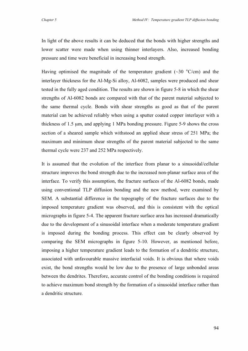
Chapter 5 Method IV: Temperature gradient TLP diffusion bonding
94
In light of the above results it can be deduced that the bonds with higher strengths and
lower scatter were made when using thinner interlayers. Also, increased bonding
pressure and time were beneficial in increasing bond strength.
Having optimised the magnitude of the temperature gradient (~30 °C/cm) and the
interlayer thickness for the Al-Mg-Si alloy, Al-6082, samples were produced and shear
tested in the fully aged condition. The results are shown in figure 5-8 in which the shear
strengths of Al-6082 bonds are compared with that of the parent material subjected to
the same thermal cycle. Bonds with shear strengths as good as that of the parent
material can be achieved reliably when using a sputter coated copper interlayer with a
thickness of 1.5 µm, and applying 1 MPa bonding pressure. Figure 5-9 shows the cross
section of a sheared sample which withstood an applied shear stress of 251 MPa; the
maximum and minimum shear strengths of the parent material subjected to the same
thermal cycle were 237 and 252 MPa respectively.
It is assumed that the evolution of the interface from planar to a sinusoidal/cellular
structure improves the bond strength due to the increased non-planar surface area of the
interface. To verify this assumption, the fracture surfaces of the Al-6082 bonds, made
using conventional TLP diffusion bonding and the new method, were examined by
SEM. A substantial difference in the topography of the fracture surfaces due to the
imposed temperature gradient was observed, and this is consistent with the optical
micrographs in figure 5-4. The apparent fracture surface area has increased dramatically
due to the development of a sinusoidal interface when a moderate temperature gradient
is imposed during the bonding process. This effect can be clearly observed by
comparing the SEM micrographs in figure 5-10. However, as mentioned before,
imposing a higher temperature gradient leads to the formation of a dendritic structure,
associated with unfavourable massive interfacial voids. It is obvious that where voids
exist, the bond strengths would be low due to the presence of large unbonded areas
between the dendrites. Therefore, accurate control of the bonding conditions is required
to achieve maximum bond strength by the formation of a sinusoidal interface rather than
a dendritic structure.
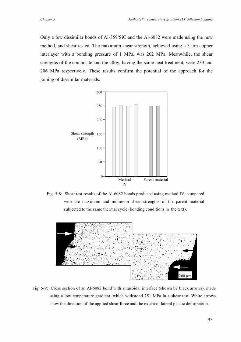
Chapter 5 Method IV: Temperature gradient TLP diffusion bonding
95
Only a few dissimilar bonds of Al-359/SiC and the Al-6082 were made using the new
method, and shear tested. The maximum shear strength, achieved using a 3 µm copper
interlayer with a bonding pressure of 1 MPa, was 202 MPa. Meanwhile, the shear
strengths of the composite and the alloy, having the same heat treatment, were 233 and
206 MPa respectively. These results confirm the potential of the approach for the
joining of dissimilar materials.
Fig. 5-9: Cross section of an Al-6082 bond with sinusoidal interface (shown by black arrows), made
using a low temperature gradient, which withstood 251 MPa in a shear test. White arrows
show the direction of the applied shear force and the extent of lateral plastic deformation.
200 µm
Fig. 5-8: Shear test results of the Al-6082 bonds produced using method IV, compared
with the maximum and minimum shear strengths of the parent material
subjected to the same thermal cycle (bonding conditions in the text).
0
50
100
150
200
250
300
Shear strength (MPa)
Parent material Method IV
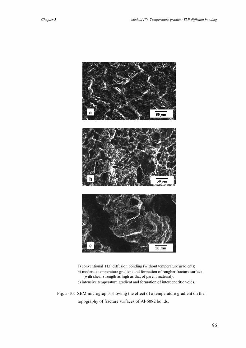
Chapter 5 Method IV: Temperature gradient TLP diffusion bonding
96
a) conventional TLP diffusion bonding (without temperature gradient); b) moderate temperature gradient and formation of rougher fracture surface
(with shear strength as high as that of parent material); c) intensive temperature gradient and formation of interdendritic voids.
Fig. 5-10: SEM micrographs showing the effect of a temperature gradient on the
topography of fracture surfaces of Al-6082 bonds.
a
b
c
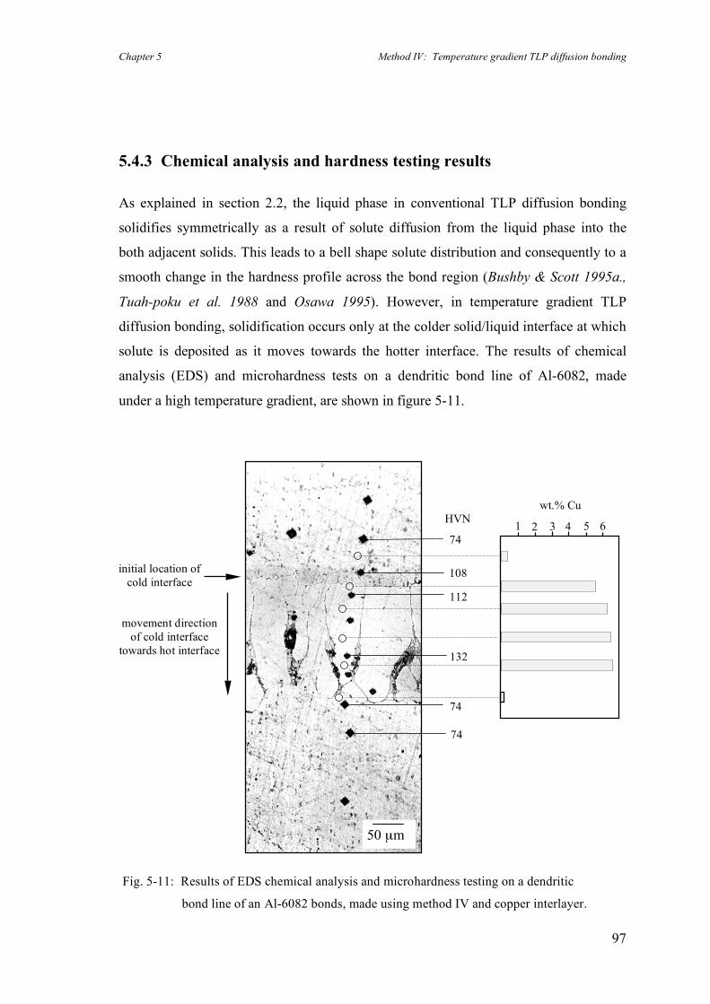
Chapter 5 Method IV: Temperature gradient TLP diffusion bonding
97
5.4.3 Chemical analysis and hardness testing results
As explained in section 2.2, the liquid phase in conventional TLP diffusion bonding
solidifies symmetrically as a result of solute diffusion from the liquid phase into the
both adjacent solids. This leads to a bell shape solute distribution and consequently to a
smooth change in the hardness profile across the bond region (Bushby & Scott 1995a.,
Tuah-poku et al. 1988 and Osawa 1995). However, in temperature gradient TLP
diffusion bonding, solidification occurs only at the colder solid/liquid interface at which
solute is deposited as it moves towards the hotter interface. The results of chemical
analysis (EDS) and microhardness tests on a dendritic bond line of Al-6082, made
under a high temperature gradient, are shown in figure 5-11.
Fig. 5-11: Results of EDS chemical analysis and microhardness testing on a dendritic
bond line of an Al-6082 bonds, made using method IV and copper interlayer.
50 µm
movement direction of cold interface
towards hot interface
initial location of cold interface
112
74
132
74
74
108
HVN wt.% Cu
1 2 3 5 4 6
Chapter 5 Method IV: Temperature gradient TLP diffusion bonding
98
There is a sharp increase in copper concentration when moving from the solid parent
material (top) towards the root of the dendrite where the solidification started (i.e. the
initial location of the colder interface). The concentration remains more or less constant
within the dendritic structure (with an average of 6 wt.% Cu) and suddenly drops to 0.2
wt.% Cu just under the tip of the dendritic zone. Bearing in mind that the initial nominal
concentration of copper is 0.1 wt.%, these results show that in this method, in contrast
to conventional TLP diffusion bonding, no substantial diffusion of copper into the bulk
material has occurred during the solidification stage. In addition, the microstructure
shows that solidification occurred isothermally, otherwise there would have been a
substantial amount of eutectic phase (Al-33 wt.% Cu) at the bond interface (see figure
6-9a which illustrates the microstructure of a bond made under non-isothermal
conditions). These observations are consistent with the assumptions made in the
analytical modelling of this method, see Chapter 6.
The hardness profile across the bonded region follows almost the same pattern as the
copper concentration. The hardness is much higher within the solidification zone
compared to the bulk of the alloy. This suggests that the presence of copper increased
the hardness within the solidification zone. The variation in the hardness around the
bond line decreased after a post-bond heat treatment (see figure 7-6), as would be
expected from diffusion of copper into the parent material.
As mentioned before, the formation of a dendritic structure is not favourable for
bonding because of the presence of interdendritic voids at the interface. However, the
above analysis helps to demonstrate the nature of the bonding process. In light of the
above results, it can be concluded that the solute concentration profile does not follow
the same pattern associated with a conventional TLP diffusion bond. This confirms that
the solidification mechanisms in these two processes are basically different (as was
explained in section 5.2).

Chapter 5 Method IV: Temperature gradient TLP diffusion bonding
99
5.5 Summary
The use of temperature gradient TLP diffusion bonding, as a novel method for joining
aluminium-based materials, proved successful. Using this approach, bonds with shear
strengths as high as those of the parent materials were produced reliably. Also, the
formation of the conventional planar bond line, which is associated particularly with
materials with stable oxide layers (e.g. aluminium-based alloys), can be avoided. This is
advantageous since planar bond lines generally are associated with not only relatively
poor mechanical properties but also a high scatter in the results. It is assumed that the
evolution of the interface from planar to a sinusoidal/cellular structure improves the
bond strength because of the increased surface area of the interface. More metal-to-
metal contact is established at the bond line, compared to a planar interface, and this
results in high strength bonds.
The kinetics of this new method rely on the diffusion of solute in the liquid phase.
Therefore, optimisation of this technique can also be used to decrease bonding times
compared with those needed for conventional TLP diffusion bonding. Assuming that
diffusion in the liquid phase is 102 to 104 times faster than bulk diffusion in a solid
phase, then the bonding times, using this method, are anticipated to be much shorter
than for conventional TLP diffusion bonding. This is examined further in Chapter 6.
Finally, it is believed that temperature gradient TLP diffusion bonding is applicable to a
wide range of aluminium-based alloys and composites. It also likely to be of benefit
when joining other materials and metallic alloys, particularly those with stable oxide
films.
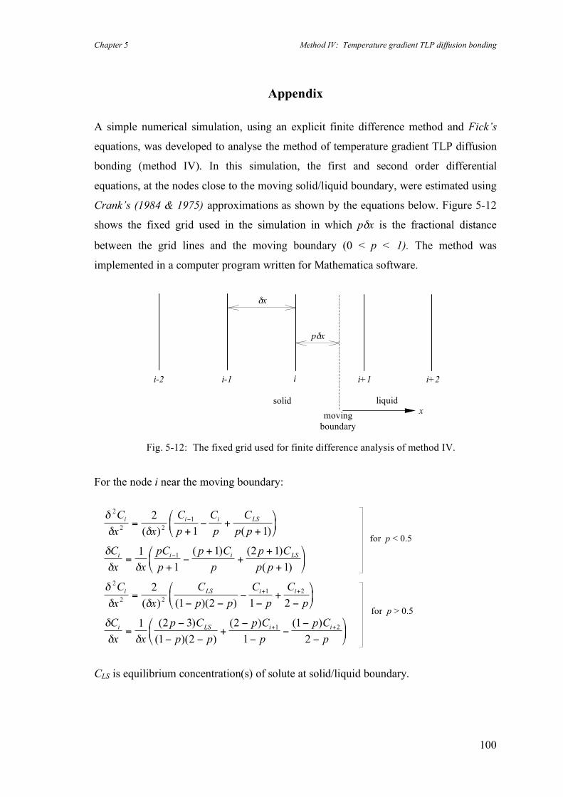
Chapter 5 Method IV: Temperature gradient TLP diffusion bonding
100
Appendix
A simple numerical simulation, using an explicit finite difference method and Fick’s
equations, was developed to analyse the method of temperature gradient TLP diffusion
bonding (method IV). In this simulation, the first and second order differential
equations, at the nodes close to the moving solid/liquid boundary, were estimated using
Crank’s (1984 & 1975) approximations as shown by the equations below. Figure 5-12
shows the fixed grid used in the simulation in which pδx is the fractional distance
between the grid lines and the moving boundary (0 < p < 1). The method was
implemented in a computer program written for Mathematica software.
For the node i near the moving boundary:
!
! !
!
! !
!
! !
!
! !
2
2 2
1
1
2
2 2
1 2
2
1 1
1
1
1 2 1
1
2
1 2 1 2
1 2 3
1
C
x x
C
p
C
p
C
p p
C
x x
pC
p
p C
p
p C
p p
C
x x
C
p p
C
p
C
p
C
x x
p C
i i i LS
i i i LS
i LS i i
i LS
=+
" ++
#
$%
&
'(
=+
"+
++
+
#
$%
&
'(
=" "
""
+"
#
$%
&
'(
="
"
"
"
+ +
( ) ( )
( ) ( )
( )
( ) ( )( )
( )
( p p
p C
p
p C
p
i i
)( )
( ) ( )
2
2
1
1
2
1 2
"+
"
""
"
"
#
$%
&
'(
+ +
CLS is equilibrium concentration(s) of solute at solid/liquid boundary.
i-2 i-1
i
i+1
i+2
pδx
δx
liquid solid
moving boundary
x
Fig. 5-12: The fixed grid used for finite difference analysis of method IV.
for p < 0.5
for p > 0.5
Chapter 6 Analytical modelling of temperature gradient TLP diffusion bonding
101
Chapter 6
6. Analytical modelling of temperature gradient TLP
diffusion bonding (method IV)
The use of temperature gradient TLP diffusion bonding resulted in reliable bonds with
shear strengths as high as those of the parent material (see section 5.4.2). An analytical
solution is proposed in this chapter which is capable of predicting precise bonding times
and bond line displacements when TLP diffusion bonding under a temperature gradient.
Based on a mass conservation approach, a simpler solution for predicting the bond line
displacement is also obtained. This latter solution is combined with the precise solution
to obtain a approximate solution for predicting the bonding time.
The results of both sets of solutions are compared to each other for different bonding
parameters. This comparison shows that the approximate solution is in agreement with
the precise solution for a range of reasonable bonding parameters and material
properties.
The bond line displacement and bonding time predicted by the model for an ideal Al-Cu
binary system are compared with the results of an experiment which was carried out on
pure aluminium and copper. The theoretical values predicted by the model are in
agreement with the experimental results. Finally, the possible application of this model
to conventional TLP diffusion bonding is discussed.
Chapter 6 Analytical modelling of temperature gradient TLP diffusion bonding
102
6.1 Background
Due to the following two main reasons, none of the existing previous models or
numerical simulations made for either TLP diffusion bonding, (Tuah-poku et al. 1988
and Zhou et al. 1995) or temperature gradient zone melting, (Pfann 1955) can be
adopted for modelling the new method of temperature gradient TLP diffusion bonding.
• Conventional TLP diffusion bonding relies on the diffusion of solute in the base
material to make isothermal solidification possible. In contrast, in temperature gradient
TLP diffusion bonding, diffusion within the liquid phase plays the main role in the
solidification process, and diffusion in the solid phase can be ignored due to the much
higher diffusion rate in the liquid phase.
• In temperature gradient zone melting, the liquid zone travels along the base material
and eventually solidifies, far from its initial location, when the temperature is decreased
below the eutectic temperature. The migration rate of the liquid layer and its effect on
the distribution of solute have been investigated in various models (Tiller 1963).
However, in temperature gradient TLP diffusion bonding, solidification of the liquid is
isothermal and occurs in the vicinity of the initial location of the interface. In fact,
microscopical observations show that the final position of the interface is very close to
its initial location.
Therefore a new approach was required to provide an analytical solution for the new
method of temperature gradient TLP diffusion bonding in order to calculate bonding
times and the displacements of the moving boundaries. It subsequently became evident
that the new approach could be used to model conventional TLP diffusion bonding by
making a small and simple assumption.
Chapter 6 Analytical modelling of temperature gradient TLP diffusion bonding
103
6.2 Precise analytical solution
The model proposed in this work is based on three basic assumptions.
1. All phases are in equilibrium with each other according to the corresponding
equilibrium phase diagram.
2. As the diffusion rate of the solute in a solid usually is at least 100 times slower than
in the liquid phase, it is reasonable to ignore the minor contribution of solid-state
diffusion when considering the kinetics of the whole process.
3. As the bonding temperature and the induced temperature gradient have to be chosen
to avoid melting of the base material, it can be concluded that the maximum width
of the solidification zone (i.e. migration distance of the liquid zone before
solidification) is much less than the distance where the temperature of the pure base
material hypothetically approaches its melting point (denoted by Xm), see figure 6-2.
Figure 6-1 shows a part of a simple binary phase diagram where the liquidus and the
solidus are assumed to be straight lines. The initial composition of the homogenised
liquid phase at the bonding temperature is CL0*.
For the sake of clarity in the mass balance approach, all terms associated with the phase
diagram in which concentrations are defined as mass/volume, have been distinguished
using the superscript symbol *. The use of appropriate units for concentration e.g. kg/m3
is essential in order to achieve an exact solution when using Fick’s diffusion laws.
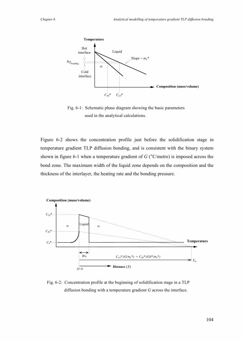
Chapter 6 Analytical modelling of temperature gradient TLP diffusion bonding
104
!Tbonding
Temperature
CL0*
Composition (mass/volume)
"
CS0*
Liquid
Slope = mL*
Cold
interface
Hot
interface
Figure 6-2 shows the concentration profile just before the solidification stage in
temperature gradient TLP diffusion bonding, and is consistent with the binary system
shown in figure 6-1 when a temperature gradient of G (°C/metre) is imposed across the
bond zone. The maximum width of the liquid zone depends on the composition and the
thickness of the interlayer, the heating rate and the bonding pressure.
CL0*
CS0*
C0*
Wo CL0*/(G/mL*) = CS0*/(Gk*/mL*)
Distance (X)X=0
Temperature
Composition (mass/volume)
! !Liquid
Xm
Fig. 6-2: Concentration profile at the beginning of solidification stage in a TLP
diffusion bonding with a temperature gradient G across the interface.
Fig. 6-1: Schematic phase diagram showing the basic parameters
used in the analytical calculations.
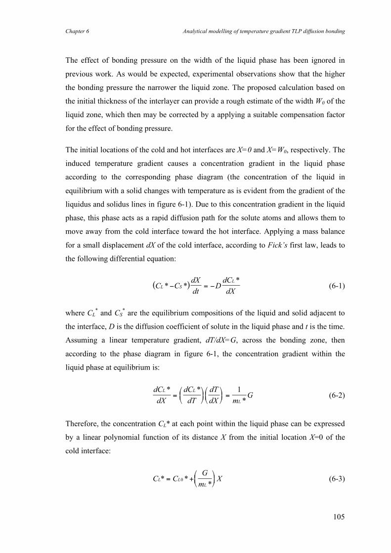
Chapter 6 Analytical modelling of temperature gradient TLP diffusion bonding
105
The effect of bonding pressure on the width of the liquid phase has been ignored in
previous work. As would be expected, experimental observations show that the higher
the bonding pressure the narrower the liquid zone. The proposed calculation based on
the initial thickness of the interlayer can provide a rough estimate of the width W0 of the
liquid zone, which then may be corrected by a applying a suitable compensation factor
for the effect of bonding pressure.
The initial locations of the cold and hot interfaces are X=0 and X=W0, respectively. The
induced temperature gradient causes a concentration gradient in the liquid phase
according to the corresponding phase diagram (the concentration of the liquid in
equilibrium with a solid changes with temperature as is evident from the gradient of the
liquidus and solidus lines in figure 6-1). Due to this concentration gradient in the liquid
phase, this phase acts as a rapid diffusion path for the solute atoms and allows them to
move away from the cold interface toward the hot interface. Applying a mass balance
for a small displacement dX of the cold interface, according to Fick’s first law, leads to
the following differential equation:
( )C CdX
dtDdC
dXL S
L
* **
! = ! (6-1)
where CL* and CS
* are the equilibrium compositions of the liquid and solid adjacent to
the interface, D is the diffusion coefficient of solute in the liquid phase and t is the time.
Assuming a linear temperature gradient, dT/dX=G, across the bonding zone, then
according to the phase diagram in figure 6-1, the concentration gradient within the
liquid phase at equilibrium is:
dC
dX
dC
dT
dT
dX mG
L L
L
* *
*=!"#
$%&!"#
$%& =
1 (6-2)
Therefore, the concentration CL* at each point within the liquid phase can be expressed
by a linear polynomial function of its distance X from the initial location X=0 of the
cold interface:
C CG
mXL L
L
* **
= +!"#
$%&0 (6-3)
Chapter 6 Analytical modelling of temperature gradient TLP diffusion bonding
106
Substitution of equation 6-3 into equation 6-1 and subsequent integration yields:
G
mX C X
DG
k mt constant
L
L
L2 12
0
**
( *) *
!"#
$%& + = '
'
!
"#
$
%& + (6-4)
where k* is the partition coefficient i.e. CS*/CL
*. With initial conditions of X=0 at t=0,
the integration constant comes out to be zero and the following equation gives the
instantaneous location of the cold interface as a function of time:
G
mX C X
DG
k mt
L
L
L2 102
0
**
( *) *
!"#
$%& + +
'
!
"#
$
%& = (6-5)
At the same time, the increased concentration of solute in front of the hot interface
lowers the melting point and the interface retreats to the left. Repeating the mass
balance approach for the hot interface, a differential equation similar to equation 6-1 can
be obtained:
( )C CdX
dtDdC
dXL
L
* **
! = !0 (6-6)
where C0* is the initial concentration of the solute in the base material. Substitution of
equation 6-3 in equation 6-6, integrating and then applying the initial condition of
X=W0 at t=0 gives an expression for the location of the hot interface as a function of
time:
( ) ( )G
mX X C C
DG
mt C C W
GW
mL
L
L
L
L2 20
20 0 0 0 0
02
** *
** *
*
!"#
$%& + ' +
!"#
$%& ' ' ' = (6-7)
As can be seen from equations 6-5 and 6-7, the transient locations of the interfaces are
independent of each other. Also, the slope of the concentration profile in the liquid
phase, G/mL*, determines the velocities of both moving boundaries for the given
materials and the bonding conditions used. Solidification of the liquid phase will be
terminated when the left-hand interface reaches the right-hand interface at a distance of
Xb (bond line displacement) within a time duration of tb (bonding time). Simultaneous
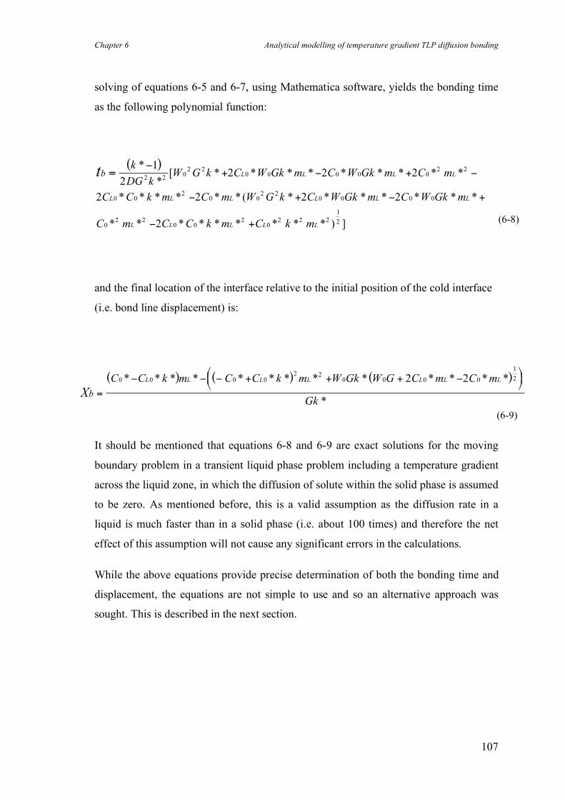
Chapter 6 Analytical modelling of temperature gradient TLP diffusion bonding
107
solving of equations 6-5 and 6-7, using Mathematica software, yields the bonding time
as the following polynomial function:
( )tb
k
DG kW G k C W Gk m C W Gk m C m
C C k m C m W G k C W Gk m C W Gk m
C m C C k m C k m
L L L L
L L L L L L
L L L L L
=!
+ ! + !
! + ! +
! +
*
*[ * * * * * * * * *
* * * * * * ( * * * * * * *
* * * * * * * * * ) ]
1
22 2 2
2 2 2 2
2
2 202 2
0 0 0 0 02 2
0 02
0 02 2
0 0 0 0
02 2
0 02
02 2 2
1
2
and the final location of the interface relative to the initial position of the cold interface
(i.e. bond line displacement) is:
( ) ( ) ( )
Xb
C C k m C C k m W Gk W G C m C m
Gk
L L L L L L L
=
! ! ! + + + !"#$ %
&'0 0 0 0
2 20 0 0 0
1
22 2* * * * * * * * * * * * *
*
It should be mentioned that equations 6-8 and 6-9 are exact solutions for the moving
boundary problem in a transient liquid phase problem including a temperature gradient
across the liquid zone, in which the diffusion of solute within the solid phase is assumed
to be zero. As mentioned before, this is a valid assumption as the diffusion rate in a
liquid is much faster than in a solid phase (i.e. about 100 times) and therefore the net
effect of this assumption will not cause any significant errors in the calculations.
While the above equations provide precise determination of both the bonding time and
displacement, the equations are not simple to use and so an alternative approach was
sought. This is described in the next section.
(6-8)
(6-9)
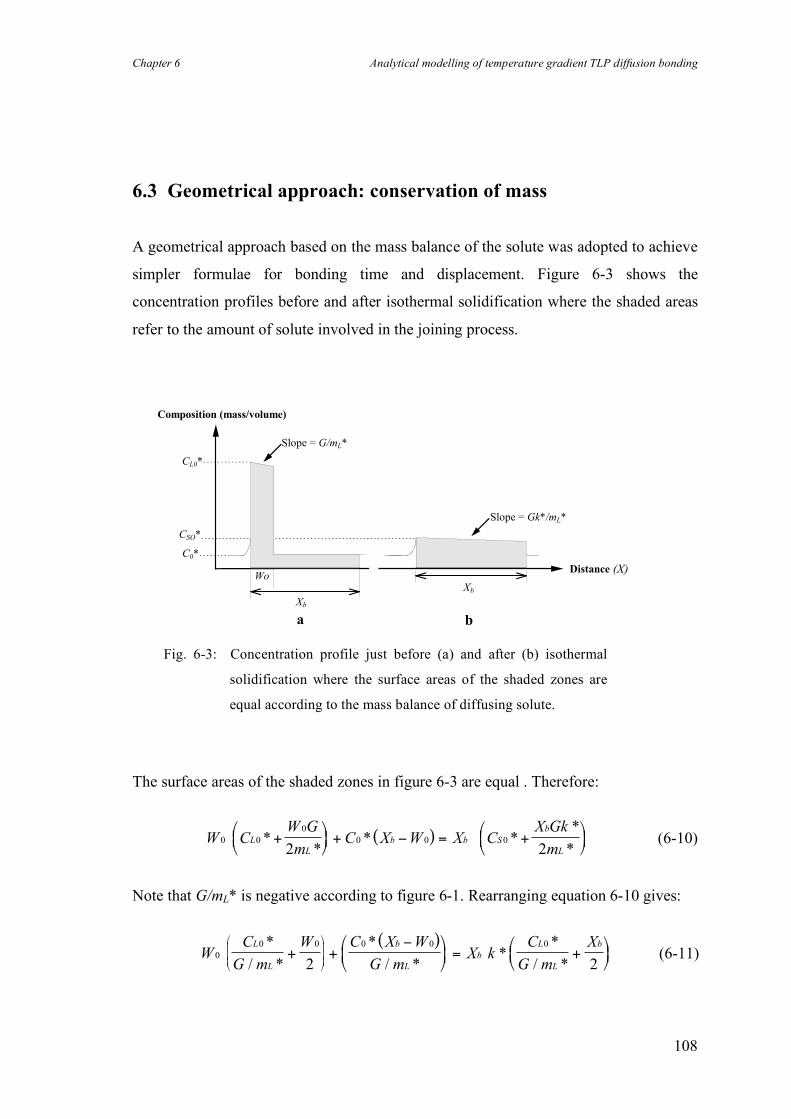
Chapter 6 Analytical modelling of temperature gradient TLP diffusion bonding
108
6.3 Geometrical approach: conservation of mass
A geometrical approach based on the mass balance of the solute was adopted to achieve
simpler formulae for bonding time and displacement. Figure 6-3 shows the
concentration profiles before and after isothermal solidification where the shaded areas
refer to the amount of solute involved in the joining process.
CL0*
CSO*
C0*
WoDistance (X)
Composition (mass/volume)
Xb
Xb
Slope = G/mL*
Slope = Gk*/mL*
a b
The surface areas of the shaded zones in figure 6-3 are equal . Therefore:
( )W CW G
mC X W X C
X Gk
mL
L
b b S
b
L
0 0
0
0 0 0
2 2*
** *
*
*+
!"#
$%& + ' = +
!"#
$%& (6-10)
Note that G/mL* is negative according to figure 6-1. Rearranging equation 6-10 gives:
( )W
C
G m
W C X W
G mX k
C
G m
XL
L
b
L
b
L
L
b
0
0 0 0 0 0
2 2
*
/ *
*
/ **
*
/ *+ +
!"
#$
%
&' = +
"#$
%&'
"
#
$$$
%
&
'''
(6-11)
Fig. 6-3: Concentration profile just before (a) and after (b) isothermal
solidification where the surface areas of the shaded zones are
equal according to the mass balance of diffusing solute.
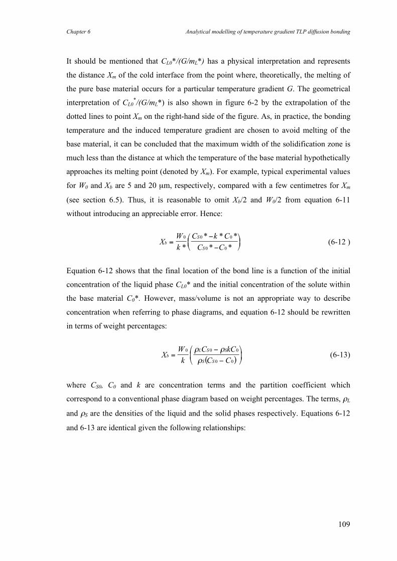
Chapter 6 Analytical modelling of temperature gradient TLP diffusion bonding
109
It should be mentioned that CL0*/(G/mL*) has a physical interpretation and represents
the distance Xm of the cold interface from the point where, theoretically, the melting of
the pure base material occurs for a particular temperature gradient G. The geometrical
interpretation of CL0*/(G/mL*) is also shown in figure 6-2 by the extrapolation of the
dotted lines to point Xm on the right-hand side of the figure. As, in practice, the bonding
temperature and the induced temperature gradient are chosen to avoid melting of the
base material, it can be concluded that the maximum width of the solidification zone is
much less than the distance at which the temperature of the base material hypothetically
approaches its melting point (denoted by Xm). For example, typical experimental values
for W0 and Xb are 5 and 20 µm, respectively, compared with a few centimetres for Xm
(see section 6.5). Thus, it is reasonable to omit Xb/2 and W0/2 from equation 6-11
without introducing an appreciable error. Hence:
XW
k
C k C
C Cb
S
S
=!
!
"#$
%&'
0 0 0
0 0*
* * *
* * (6-12 )
Equation 6-12 shows that the final location of the bond line is a function of the initial
concentration of the liquid phase CL0* and the initial concentration of the solute within
the base material C0*. However, mass/volume is not an appropriate way to describe
concentration when referring to phase diagrams, and equation 6-12 should be rewritten
in terms of weight percentages:
( )X
W
k
C kC
C Cb
L S S
S S
=!
!
"
#$
%
&'
0 0 0
0 0
( (
( (6-13)
where CS0, C0 and k are concentration terms and the partition coefficient which
correspond to a conventional phase diagram based on weight percentages. The terms, ρL
and ρS are the densities of the liquid and the solid phases respectively. Equations 6-12
and 6-13 are identical given the following relationships:
Chapter 6 Analytical modelling of temperature gradient TLP diffusion bonding
110
k kS
L
* =!
! (6-14)
C C
C C
C C
S S S
o S
L L L
0 0
0
0
*
*
*
=
=
=
!
!
!
"
"
"
(6-15)
It is worth mentioning that using atomic or weight percentage (rather than mass per unit
volume) as the concentration unit in the basic diffusion equations, which has been done
in some of the previous analyses, can lead to major errors in the calculations unless the
partial molar volumes of each constituting element in all phases, or the densities of the
phases involved, are sufficiently similar. For instance, for the case in which the
densities are close enough, Xb is given by:
XW
k
C kC
C Cb
S
S
=!
!
"#$
%&'
0 0 0
0 0
(6-16)
In equations 6-13 and 6-16, the width of the reaction zone Xb approaches infinity as the
initial concentration C0 reaches the equilibrium concentration of the solid phase CS0 in
equilibrium with the liquid phase CL0. This simply means that solidification in this
particular case will not be terminated as the movement of the boundaries is not
associated with the depletion of solute in the liquid phase. Although not exactly the
same, this is very similar to zone refining in which the width of the molten region
remains constant as the hot liquid zone is moved down a solid bar.
It is evident that the geometrical approach (conversation of mass) results in equations 6-
13 and 6-16 which are considerably simpler than the precise analytical solution given by
equation 6-9 for the bond line displacement.
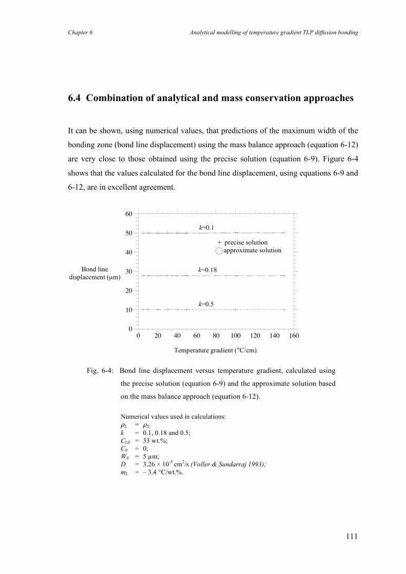
Chapter 6 Analytical modelling of temperature gradient TLP diffusion bonding
111
6.4 Combination of analytical and mass conservation approaches
It can be shown, using numerical values, that predictions of the maximum width of the
bonding zone (bond line displacement) using the mass balance approach (equation 6-12)
are very close to those obtained using the precise solution (equation 6-9). Figure 6-4
shows that the values calculated for the bond line displacement, using equations 6-9 and
6-12, are in excellent agreement.
0
10
20
30
40
50
60
0 20 40 60 80 100 120 140 160
Temperature gradient (°C/cm)
Bond line displacement (µm)
k=0.18
k=0.1
k=0.5
Fig. 6-4: Bond line displacement versus temperature gradient, calculated using
the precise solution (equation 6-9) and the approximate solution based
on the mass balance approach (equation 6-12).
Numerical values used in calculations: ρL = ρS; k = 0.1, 0.18 and 0.5; CL0 = 33 wt.%; C0 = 0; W0 = 5 µm; D = 3.26 × 10⁻⁵ cm2/s (Voller & Sundarraj 1993); mL = – 3.4 °C/wt.%.
+ precise solution approximate solution
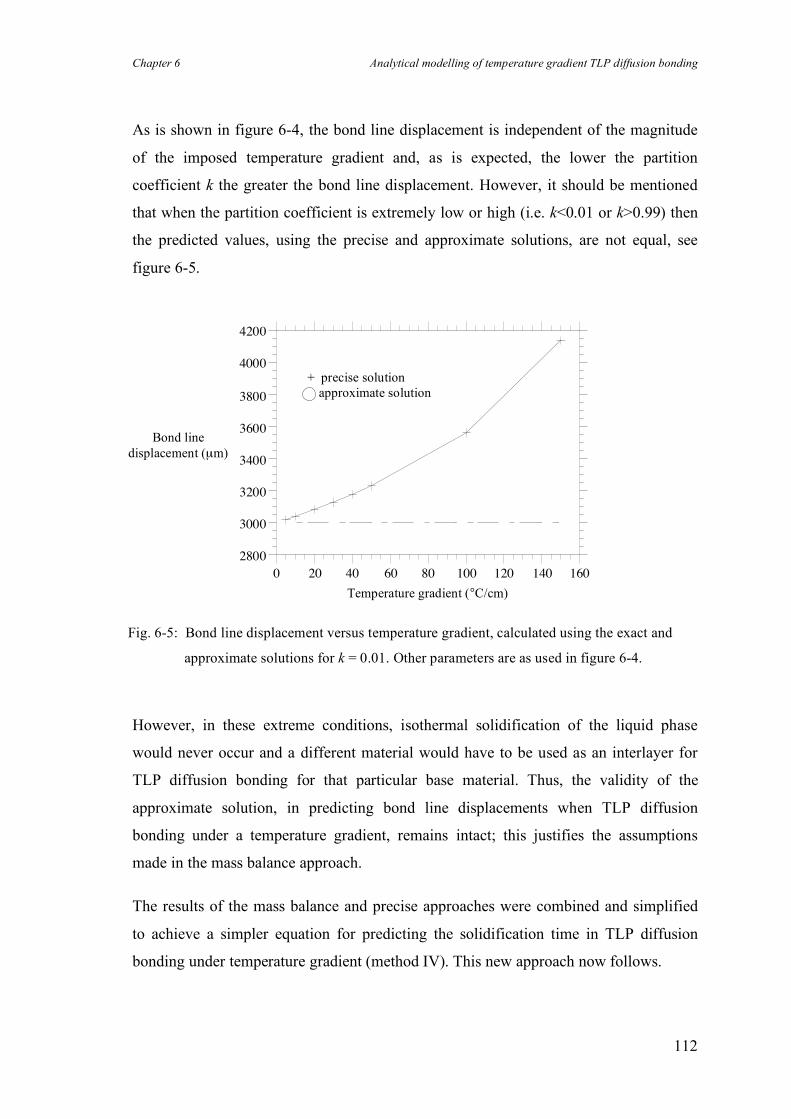
Chapter 6 Analytical modelling of temperature gradient TLP diffusion bonding
112
As is shown in figure 6-4, the bond line displacement is independent of the magnitude
of the imposed temperature gradient and, as is expected, the lower the partition
coefficient k the greater the bond line displacement. However, it should be mentioned
that when the partition coefficient is extremely low or high (i.e. k<0.01 or k>0.99) then
the predicted values, using the precise and approximate solutions, are not equal, see
figure 6-5.
2800
3000
3200
3400
3600
3800
4000
4200
0 20 40 60 80 100 120 140 160
However, in these extreme conditions, isothermal solidification of the liquid phase
would never occur and a different material would have to be used as an interlayer for
TLP diffusion bonding for that particular base material. Thus, the validity of the
approximate solution, in predicting bond line displacements when TLP diffusion
bonding under a temperature gradient, remains intact; this justifies the assumptions
made in the mass balance approach.
The results of the mass balance and precise approaches were combined and simplified
to achieve a simpler equation for predicting the solidification time in TLP diffusion
bonding under temperature gradient (method IV). This new approach now follows.
Temperature gradient (°C/cm)
Bond line displacement (µm)
Fig. 6-5: Bond line displacement versus temperature gradient, calculated using the exact and
approximate solutions for k = 0.01. Other parameters are as used in figure 6-4.
+ precise solution approximate solution
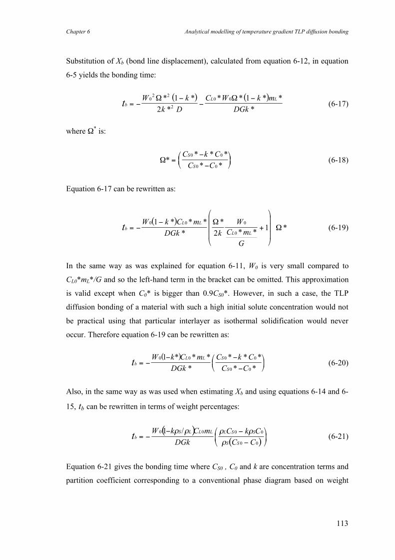
Chapter 6 Analytical modelling of temperature gradient TLP diffusion bonding
113
Substitution of Xb (bond line displacement), calculated from equation 6-12, in equation
6-5 yields the bonding time:
( ) ( )tb
L LW k
k D
C W k m
DGk= !
!!
!02 2
2
0 01
2
1" "* *
*
* * * *
* (6-17)
where Ω* is:
!** * *
* *=
"
"
#$%
&'(
C k C
C C
S
S
0 0
0 0
(6-18)
Equation 6-17 can be rewritten as:
( )tb
L L
L L
W k C m
DGk k
W
C m
G
= !!
+
"
#
$$$
%
&
'''
0 0 0
0
1
21
* * *
*
*
* **
(( (6-19)
In the same way as was explained for equation 6-11, W0 is very small compared to
CL0*mL*/G and so the left-hand term in the bracket can be omitted. This approximation
is valid except when C0* is bigger than 0.9CS0*. However, in such a case, the TLP
diffusion bonding of a material with such a high initial solute concentration would not
be practical using that particular interlayer as isothermal solidification would never
occur. Therefore equation 6-19 can be rewritten as:
( )tb
L L S
S
W k C m
DGk
C k C
C C= !
! !
!
"#$
%&'
0 0 0 0
0 0
1 * * *
*
* * *
* * (6-20)
Also, in the same way as was used when estimating Xb and using equations 6-14 and 6-
15, tb can be rewritten in terms of weight percentages:
( )( )
tbS L L L L S S
S S
W k C m
DGk
C k C
C C= !
! !
!
"
#$
%
&'
0 0 0 0
0 0
1 ( ( ( (
(
/ (6-21)
Equation 6-21 gives the bonding time where CS0 , C0 and k are concentration terms and
partition coefficient corresponding to a conventional phase diagram based on weight
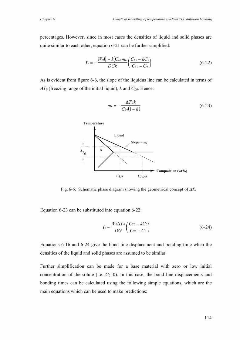
Chapter 6 Analytical modelling of temperature gradient TLP diffusion bonding
114
percentages. However, since in most cases the densities of liquid and solid phases are
quite similar to each other, equation 6-21 can be further simplified:
( )tb
L L S
S
W k C m
DGk
C kC
C C= !
! !
!
"#$
%&'
0 0 0 0
0 0
1 (6-22)
As is evident from figure 6-6, the slope of the liquidus line can be calculated in terms of
ΔT0 (freezing range of the initial liquid), k and CL0. Hence:
( )
mT k
C kL
L
= !!
" 0
0 1 (6-23)
!T0
Temperature
CL0 CL0/K
Composition (wt%)
"
Liquid
Slope = mL
Equation 6-23 can be substituted into equation 6-22:
tbS
S
W T
DG
C kC
C C=
!
!
"#$
%&'
0 0 0 0
0 0
( (6-24)
Equations 6-16 and 6-24 give the bond line displacement and bonding time when the
densities of the liquid and solid phases are assumed to be similar.
Further simplification can be made for a base material with zero or low initial
concentration of the solute (i.e. C0=0). In this case, the bond line displacements and
bonding times can be calculated using the following simple equations, which are the
main equations which can be used to make predictions:
Fig. 6-6: Schematic phase diagram showing the geometrical concept of ΔT0.
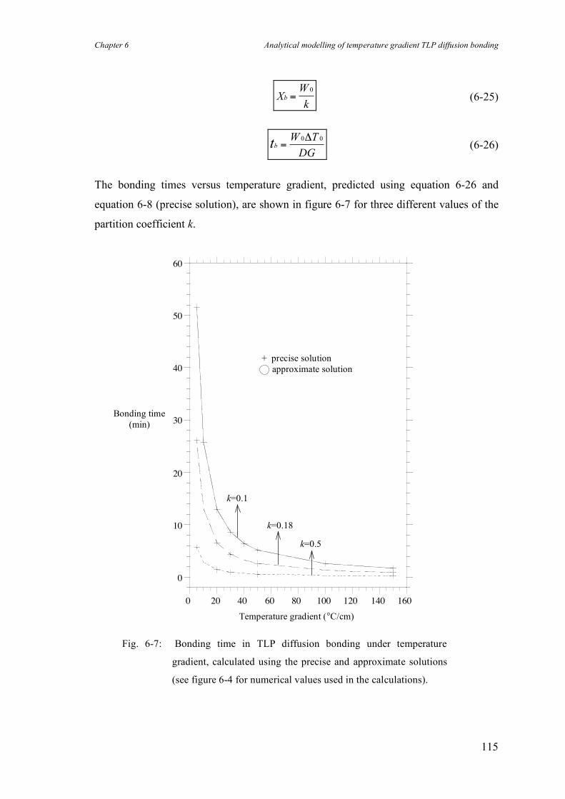
Chapter 6 Analytical modelling of temperature gradient TLP diffusion bonding
115
XW
kb =
0
(6-25)
tbW T
DG=
0 0! (6-26)
The bonding times versus temperature gradient, predicted using equation 6-26 and
equation 6-8 (precise solution), are shown in figure 6-7 for three different values of the
partition coefficient k.
0
10
20
30
40
50
60
0 20 40 60 80 100 120 140 160
Fig. 6-7: Bonding time in TLP diffusion bonding under temperature
gradient, calculated using the precise and approximate solutions
(see figure 6-4 for numerical values used in the calculations).
Temperature gradient (°C/cm)
Bonding time (min)
k=0.1
k=0.18
k=0.5
+ precise solution approximate solution
Chapter 6 Analytical modelling of temperature gradient TLP diffusion bonding
116
Summary
Using figures 6-4 and 6-7, several points are immediately obvious:
• As the bonding temperature is normally chosen to be as close as possible to the lowest
melting temperature to avoid the disadvantages associated with a high temperature
process, the bonding time for a particular base material and interlayer can only be varied
by changing the induced temperature gradient, G. This means that the higher the
temperature gradient, the shorter the bonding time.
• As in conventional TLP diffusion bonding, the solidification time decreases as the
partition coefficient increases. However, increasing the magnitude of the temperature
gradient reduces the influence of the partition coefficient on the bonding time. The
bonding times, for binary systems with different partition coefficients, become shorter
and approach each other as the temperature gradient increases.
• The approach proposed in this work may also be applicable to conventional TLP
diffusion bonding when, nominally, a temperature gradient is not imposed. The
presence of even a very small temperature gradient across the interface will accelerate
the isothermal solidification substantially. This is a new approach for modelling
conventional TLP diffusion bonding and it may explain the existing inconsistency
between predictions from previous models and experimental results.
• The displacement of the interface is merely a function of the initial width of the liquid
phase and the partition coefficient. Both the interface displacement and the bonding
time are linear functions of the initial width of the liquid phase.
The displacements of the interface and the bonding times in an Al-Cu binary system, for
various widths of the liquid phase, were calculated and results are shown in figure 6-8.
The effect of the magnitude of the temperature gradient on bonding time for this binary
system is shown in figure 6-7 (i.e. k = 0.18). The calculated values have been used for
experimental verification of the proposed modelling, as is described in the next section.
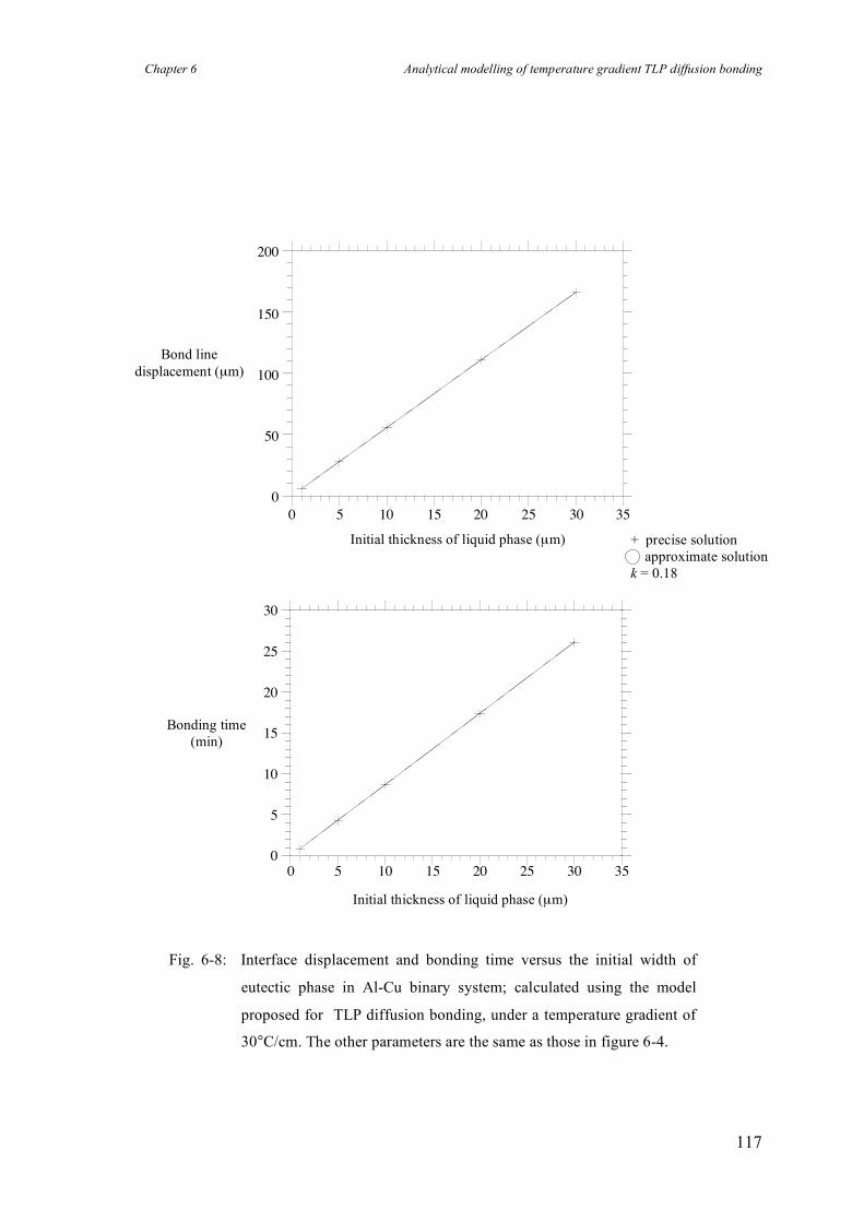
Chapter 6 Analytical modelling of temperature gradient TLP diffusion bonding
117
0
50
100
150
200
0 5 10 15 20 25 30 35
0
5
10
15
20
25
30
0 5 10 15 20 25 30 35
Fig. 6-8: Interface displacement and bonding time versus the initial width of
eutectic phase in Al-Cu binary system; calculated using the model
proposed for TLP diffusion bonding, under a temperature gradient of
30°C/cm. The other parameters are the same as those in figure 6-4.
Bond line displacement (µm)
Initial thickness of liquid phase (µm)
Initial thickness of liquid phase (µm)
Bonding time (min)
+ precise solution approximate solution k = 0.18
Chapter 6 Analytical modelling of temperature gradient TLP diffusion bonding
118
6.5 Experimental verification of modelling
In order to verify the proposed analytical model for temperature gradient TLP diffusion
bonding, preliminary experiments on bonding pure aluminium, using copper interlayers,
have been carried out. The maximum width of the Al-Cu eutectic phase W0, calculated
from the phase diagram and relative densities, can be up to about 7 times thicker than
the interlayer. Although TLP diffusion bonding is considered to be a low pressure
bonding method, a preliminary investigation in the current work showed that the bond
strength decreases drastically when the bonding pressure is below a certain amount,
probably as a consequence of poor surface contact. Hence, the use of a minimal applied
bonding pressure is essential in order to achieve high bond strengths. On the other hand,
the bonding pressure has a drastic effect on the actual width of the liquid zone, reducing
the width considerably, and this has not been allowed for in previous studies of TLP
diffusion bonding.
The actual width of the liquid layer in a conventional TLP diffusion bonding was
measured experimentally and then this result was substituted in equation 6-25 to
calculate the displacement of the bond line in a bond made using the new method.
Finally, the calculated displacement was compared with that measured experimentally.
The accuracy of the model in predicting the bond time is also evaluated.
6.5.1 Experimental procedure and results
Even when using constant pressure loading equipment, the bonding pressure drops
suddenly in the course of bonding when melting occurs, and it takes a few seconds for
the loading system to return the pressure to its set value. This pressure variation on
liquid formation was used to measure the width of the liquid eutectic phase when
bonding pure aluminium using a 12.5 µm thick copper interlayer. By turning off the
heating system as soon as the pressure drop commenced, it was possible to freeze the
liquid phase before it could be squeezed out by subsequent restoration of the pressure.
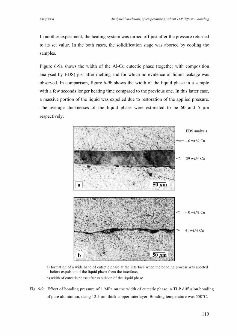
Chapter 6 Analytical modelling of temperature gradient TLP diffusion bonding
119
In another experiment, the heating system was turned off just after the pressure returned
to its set value. In the both cases, the solidification stage was aborted by cooling the
samples.
Figure 6-9a shows the width of the Al-Cu eutectic phase (together with composition
analysed by EDS) just after melting and for which no evidence of liquid leakage was
observed. In comparison, figure 6-9b shows the width of the liquid phase in a sample
with a few seconds longer heating time compared to the previous one. In this latter case,
a massive portion of the liquid was expelled due to restoration of the applied pressure.
The average thicknesses of the liquid phase were estimated to be 60 and 5 µm
respectively.
a) formation of a wide band of eutectic phase at the interface when the bonding process was aborted before expulsion of the liquid phase from the interface;
b) width of eutectic phase after expulsion of the liquid phase.
Fig. 6-9: Effect of bonding pressure of 1 MPa on the width of eutectic phase in TLP diffusion bonding
of pure aluminium, using 12.5 µm thick copper interlayer. Bonding temperature was 550°C.
b
a
39 wt.% Cu
∼ 0 wt.% Cu
41 wt.% Cu
∼ 0 wt.% Cu
EDS analysis
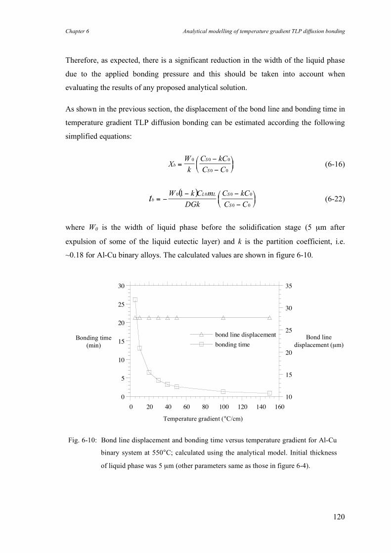
Chapter 6 Analytical modelling of temperature gradient TLP diffusion bonding
120
Therefore, as expected, there is a significant reduction in the width of the liquid phase
due to the applied bonding pressure and this should be taken into account when
evaluating the results of any proposed analytical solution.
As shown in the previous section, the displacement of the bond line and bonding time in
temperature gradient TLP diffusion bonding can be estimated according the following
simplified equations:
XW
k
C kC
C Cb
S
S
=!
!
"#$
%&'
0 0 0
0 0
(6-16)
( )tb
L L S
S
W k C m
DGk
C kC
C C= !
! !
!
"#$
%&'
0 0 0 0
0 0
1 (6-22)
where W0 is the width of liquid phase before the solidification stage (5 µm after
expulsion of some of the liquid eutectic layer) and k is the partition coefficient, i.e.
~0.18 for Al-Cu binary alloys. The calculated values are shown in figure 6-10.
0
5
10
15
20
25
30
10
15
20
25
30
35
0 20 40 60 80 100 120 140 160
bonding time
bond line displacement
Temperature gradient (°C/cm)
Bonding time (min)
Bond line displacement (µm)
Fig. 6-10: Bond line displacement and bonding time versus temperature gradient for Al-Cu
binary system at 550°C; calculated using the analytical model. Initial thickness
of liquid phase was 5 µm (other parameters same as those in figure 6-4).
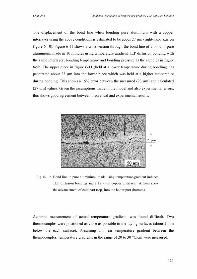
Chapter 6 Analytical modelling of temperature gradient TLP diffusion bonding
121
The displacement of the bond line when bonding pure aluminium with a copper
interlayer using the above conditions is estimated to be about 27 µm (right-hand axis on
figure 6-10). Figure 6-11 shows a cross section through the bond line of a bond in pure
aluminium, made in 10 minutes using temperature gradient TLP diffusion bonding with
the same interlayer, bonding temperature and bonding pressure as the samples in figure
6-9b. The upper piece in figure 6-11 (held at a lower temperature during bonding) has
penetrated about 23 µm into the lower piece which was held at a higher temperature
during bonding. This shows a 15% error between the measured (23 µm) and calculated
(27 µm) values. Given the assumptions made in the model and also experimental errors,
this shows good agreement between theoretical and experimental results.
Accurate measurement of actual temperature gradients was found difficult. Two
thermocouples were positioned as close as possible to the faying surfaces (about 2 mm
below the each surface). Assuming a linear temperature gradient between the
thermocouples, temperature gradients in the range of 20 to 30 °C/cm were measured.
Fig. 6-11: Bond line in pure aluminium, made using temperature-gradient induced
TLP diffusion bonding and a 12.5 µm copper interlayer. Arrows show
the advancement of cold part (top) into the hotter part (bottom).
23 µm
Chapter 6 Analytical modelling of temperature gradient TLP diffusion bonding
122
Metallographic examination of the bonds made using a bonding time of 5 minutes or
more showed that isothermal solidification was completed in all bonds as no evidence
of retained eutectic phase was observed at the interfaces. This is consistent with the
values predicted by the proposed model (left-hand axis on figure 6-10). Further
investigations in this area will be undertaken in future work.
Chapter 6 Analytical modelling of temperature gradient TLP diffusion bonding
123
6.6 Summary
The analytical solution proposed for the new method of temperature gradient TLP
diffusion bonding is in a good agreement with the experimental results for boundary
displacement. It is evident that imposing a temperature gradient resulted in complete
solidification in short bonding times; no evidence of the eutectic phase was observed
when the bonding time was as short as 5 minutes. However, predicting bonding times,
using the proposed method, requires accurate data regarding the actual temperature
gradient across the liquid phase.
It is further believed that the model developed is applicable to conventional TLP
diffusion bonding and may provide a more rigorous description of TLP diffusion
bonding when, nominally, a temperature gradient is not imposed. This is because, in
practice, a small difference is likely to exist between the temperatures at the two
solid/liquid interfaces whenever TLP diffusion bonding is attempted. This means that
bonding will take place as a consequence of the mechanism described above. This is a
completely new way to describe the process and may be more consistent with the results
that are achieved. Moreover, it provides a means to rigorously model TLP diffusion
bonding, overcoming some of the assumptions required in previous models. Further
work will be undertaken to demonstrate this.
Finally the initial experiments reported in this work showed that, as would be expected,
bonding pressure has a drastic effect on the actual width of the liquid phase in TLP
diffusion bonding. This has not been taken into account in previous analyses of the
process.
Chapter 7 Methods V and VI: TLP diffusion bonding in air
124
Chapter 7
7. Methods V and VI: New methods for TLP diffusion
bonding aluminium alloys in air
7.1 Introduction
Most alloys and metallic composites have stable oxide layers which can inhibit the
interdiffusion of atoms across the interface when solid-state diffusion bonding.
Therefore, diffusion bonding of these materials is normally conducted in vacuum in
order to reduce the high temperature oxidation of the faying surfaces. Aluminium-based
materials, in particular, are notoriously difficult to diffusion bond due to the presence of
tenacious and chemically stable surface oxide layers.
Transient liquid phase (TLP) diffusion bonding has the potential to overcome the
problem caused by the presence of stable surface oxides. However, the bonding process
has to be carried out in vacuum, typically 10-3-10-5 mbar, to prevent any increase in the
thickness of surface oxide layers and also to avoid high temperature oxidation of the
interlayer.
Although the new methods developed in this research are capable of reliably producing
high strength bonds, the entire bonding process (when using methods I and IV) or part
of it (when using methods II and III) needs to be carried out in vacuum. The necessity
of conducting the joining process in vacuum requires complicated bonding equipment.
Also, the overall bonding time increases substantially when a vacuum has to be
established before bonding can start. As an example, the actual bonding time when
using the fourth method, excluding the air evacuation stage, was about 10 minutes while
Chapter 7 Methods V and VI: TLP diffusion bonding in air
125
it normally takes an additional 20 minutes to evacuate the chamber down to a pressure
of about 10-4 mbar. Thus, the overall bonding time is increased by a factor of three due
to the time required to achieve a reasonable vacuum. The size of the parts to be joined is
also limited by the size of the vacuum chamber. These limitations, associated with
vacuum systems, become even more restrictive when conducting diffusion bonding on a
commercial scale.
It can be concluded that the necessity of joining in vacuum in order to form bonds with
reasonable mechanical strengths has restricted the application of TLP diffusion bonding.
The initial investment, running and maintenance costs will be decreased if bonding is
carried out in air.
In the research described in this chapter, two new methods for TLP diffusion bonding
have been developed which are capable of producing high strength aluminium bonds in
air. In contrast to most previous attempts to diffusion bond in air, the new methods do
not exploit any particular surface preparation to prevent the oxidation of the faying
surfaces, e.g. coating , roll-cladding etc. (see section 2.6).
In comparison to conventional TLP diffusion bonding in vacuum, the use of these new
methods should drastically reduce the costs of the bonding process. There are also fewer
limitations on the size of the parts to be joined in air. Therefore, a much wider range of
applications for TLP diffusion bonding is anticipated.
Finally, bearing in mind that aluminium-based materials are among the most difficult
materials to bond in air, the new methods are expected to be applicable to many other
materials.
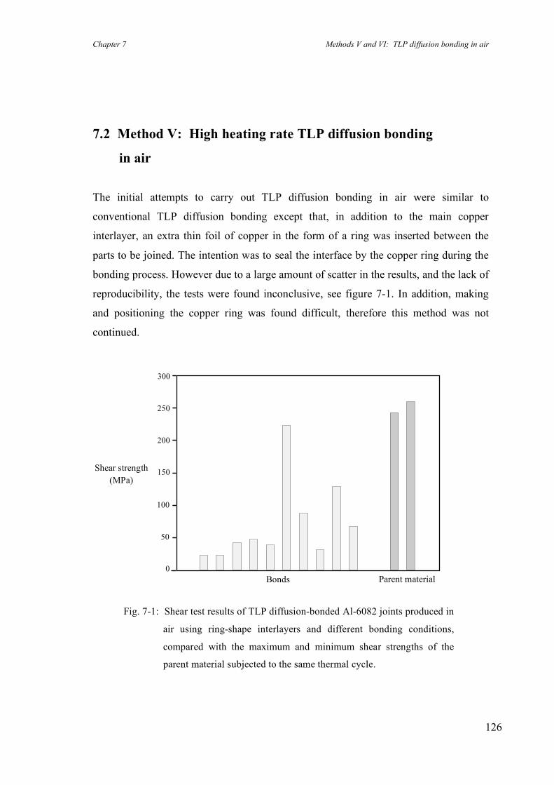
Chapter 7 Methods V and VI: TLP diffusion bonding in air
126
7.2 Method V: High heating rate TLP diffusion bonding
in air
The initial attempts to carry out TLP diffusion bonding in air were similar to
conventional TLP diffusion bonding except that, in addition to the main copper
interlayer, an extra thin foil of copper in the form of a ring was inserted between the
parts to be joined. The intention was to seal the interface by the copper ring during the
bonding process. However due to a large amount of scatter in the results, and the lack of
reproducibility, the tests were found inconclusive, see figure 7-1. In addition, making
and positioning the copper ring was found difficult, therefore this method was not
continued.
Fig. 7-1: Shear test results of TLP diffusion-bonded Al-6082 joints produced in
air using ring-shape interlayers and different bonding conditions,
compared with the maximum and minimum shear strengths of the
parent material subjected to the same thermal cycle.
Shear strength (MPa)
0
50
100
150
200
250
300
Parent material Bonds
Chapter 7 Methods V and VI: TLP diffusion bonding in air
127
Consequently, another method was developed to overcome the problems associated
with bonding in air. This new method (method V) is referred to as “High heating rate
TLP diffusion bonding”, see section 3.2.2 for experimental procedure.
Theoretical aspects of the new method are described below in terms of the major
features of aluminium-based materials (as the parent material) and copper (as the
interlayer). The method is, however, applicable to a much wider range of parent
materials and interlayers.
Aluminium and oxygen have such a high chemical affinity that a new oxide layer
effectively forms immediately after surface cleaning. A few nanometres of oxide are
sufficient to isolate the base material from ambient oxygen, with the consequence that
the rate of oxidation decreases rapidly following the initial oxidation. This intrinsic
feature of aluminium-based materials has been considered to be an obstacle when
diffusion bonding these materials. However, from a different point of view, it can be
beneficial when TLP diffusion bonding in air! According to previous experience when
TLP diffusion bonding aluminium alloys using a copper interlayer in vacuum, the liquid
phase forms within a few seconds after reaching the eutectic temperature of the Al-Cu
binary system (i.e. ~548°C). With the formation of the liquid phase, the interface then
becomes sealed and so a vacuum is not required for the rest of the bonding process. It
can be concluded that any increase in the thickness of the aluminium oxide layer from
its initial condition occurs mostly during the heating stage and ceases when the liquid
phase seals the interface. Theoretically, the relatively impermeable and chemically
stable surface aluminium oxide layers should minimise further oxidation of the faying
surfaces during the short heating stage. Accordingly, the higher the heating rate, the less
the increase in the thickness of oxide layers – this is the main requirement for high
heating rate TLP diffusion bonding in air (method V).
This approach is consistent with Scamans & Butler’s report (1975) on the oxidation
processes of pure aluminium and various aluminium alloys, in which they studied the
effect of temperature (in the range of 400 to 520°C) on the morphology and structure of
oxides formed in vacuum and air. Their in situ observations of oxidation showed that,
apart from the already expected higher oxidation rate in air compared to that in vacuum,
the morphology and structure of the oxide layers formed in air and vacuum are quite
Chapter 7 Methods V and VI: TLP diffusion bonding in air
128
similar. In addition, they reported that there was an incubation time for oxidation and
this incubation period decreases drastically with increasing temperature. Even so, the
incubation time for the formation of MgO crystallites on an Al-Mg-Zn alloy was
reported to be as long as one minute at 500°C. Therefore, the surface composition and
the initial thickness of a pre-existing oxide should not change markedly for a short time
after reaching a high temperature. This brief delay in the onset of the oxidation process
at the beginning of a heating cycle is the basis of the new approach for TLP diffusion
bonding in air.
Copper is extensively used as a sealant in vacuums and pressurised systems. Hence the
copper interlayer, used for TLP diffusion bonding, can act also as a sealant and so
reducing the oxidation of itself and the aluminium alloy during the heating stage
(provided the thickness of interlayer is adequate). Obviously, the faying surfaces should
be flat and smooth to ensure proper contact between the interlayer and alloy. In this new
method, good contact is required to reduce the oxidation due to the exposure of the
interface to air (see section 3.2.1). Also, the higher the initial bonding pressure, the
better is the sealing of the interface, providing that the bonding pressure does not
subsequently exceed the yield stress of the parent material at the bonding temperature.
Note that lack of good contact in the initial stage of conventional TLP diffusion bonding
in vacuum can be tolerated as the liquid phase forms, normally with a thickness of a few
times that of the thickness of the interlayer, and consequently fills any crevices.
Briefly, this new method relies on the combination of a rapid heating stage and
excellent contact between the faying surfaces in order to minimise the detrimental
effects of oxidation which may otherwise occur when diffusion bonding in air.
7.2.1 Results of method V and discussion
In the experimental verification of the method, Al-6082 was used as the parent material
and copper foils as the interlayer. With a fairly constant heating rate of 20°C per second
and a constant bonding temperature of 550°C for all specimens, the effects of time (5
and 10 minutes including 30 seconds for the heating stage) and the thickness of copper

Chapter 7 Methods V and VI: TLP diffusion bonding in air
129
interlayer (1 and 8 µm) on bond strength were investigated. Note that the rapid thermal
expansion of the specimens during the heating stage increased the pressure up to 10
MPa for a short time before the loading system resumed the pre-set pressure (7 MPa).
To optimise the bonding conditions for this new method, up to 40 bonding trials were
carried out. Having optimised the bonding conditions for Al-6082 using a 12.5 µm
copper interlayer with a bonding condition of [T 550 / P 7 / t 5 / M V], samples were
produced and shear tested in the fully aged condition. In figure 7-2, the shear strengths
of Al-6082 bonds have been compared with that of the parent material subjected to the
same thermal cycle. Bonds with shear strengths as high as 206 MPa (90% that of the
parent material) were achieved. The minimum bond strength was 173 MPa (75% that of
the parent material).
Figure 7-3 shows the cross section of a sheared sample made using a 7 µm thick copper
interlayer with a bonding condition of [T 550 / P 6 / t 5 / M V] which withstood an
applied shear stress of 183 MPa (80% of the shear strength of the parent material in the
Fig. 7-2: Shear test results of the Al-6082 bonds produced using method V for TLP
diffusion bonding in air, compared with the maximum and minimum shear
strengths of the parent material subjected to the same thermal cycle (bonding
condition: [T 550 / P 7 / t 5 / M V] using a 12.5 µm Cu interlayer).
Parent material
Shear strength (MPa)
Bonds 0
50
100
150
200
250
300
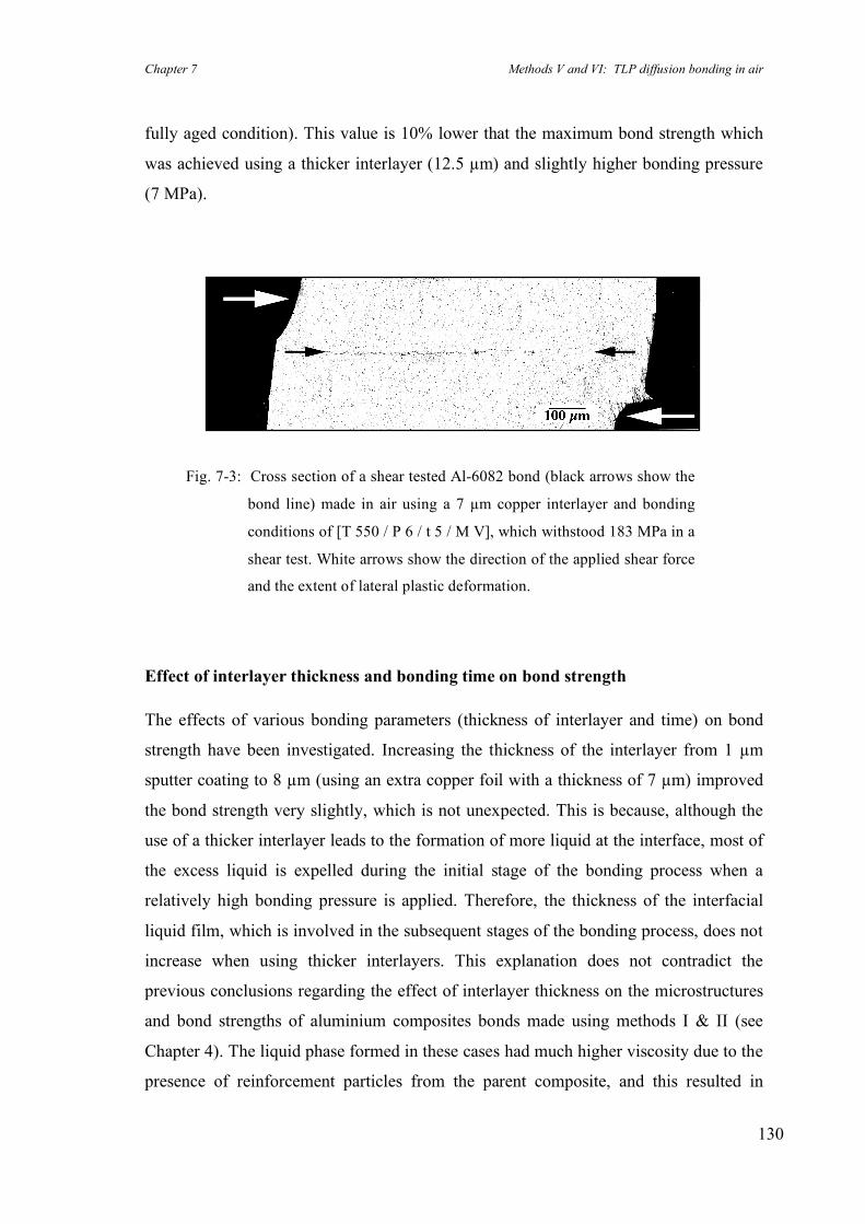
Chapter 7 Methods V and VI: TLP diffusion bonding in air
130
fully aged condition). This value is 10% lower that the maximum bond strength which
was achieved using a thicker interlayer (12.5 µm) and slightly higher bonding pressure
(7 MPa).
Effect of interlayer thickness and bonding time on bond strength
The effects of various bonding parameters (thickness of interlayer and time) on bond
strength have been investigated. Increasing the thickness of the interlayer from 1 µm
sputter coating to 8 µm (using an extra copper foil with a thickness of 7 µm) improved
the bond strength very slightly, which is not unexpected. This is because, although the
use of a thicker interlayer leads to the formation of more liquid at the interface, most of
the excess liquid is expelled during the initial stage of the bonding process when a
relatively high bonding pressure is applied. Therefore, the thickness of the interfacial
liquid film, which is involved in the subsequent stages of the bonding process, does not
increase when using thicker interlayers. This explanation does not contradict the
previous conclusions regarding the effect of interlayer thickness on the microstructures
and bond strengths of aluminium composites bonds made using methods I & II (see
Chapter 4). The liquid phase formed in these cases had much higher viscosity due to the
presence of reinforcement particles from the parent composite, and this resulted in
Fig. 7-3: Cross section of a shear tested Al-6082 bond (black arrows show the
bond line) made in air using a 7 µm copper interlayer and bonding
conditions of [T 550 / P 6 / t 5 / M V], which withstood 183 MPa in a
shear test. White arrows show the direction of the applied shear force
and the extent of lateral plastic deformation.
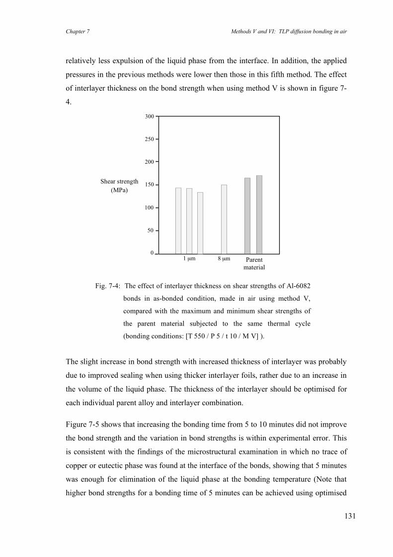
Chapter 7 Methods V and VI: TLP diffusion bonding in air
131
relatively less expulsion of the liquid phase from the interface. In addition, the applied
pressures in the previous methods were lower then those in this fifth method. The effect
of interlayer thickness on the bond strength when using method V is shown in figure 7-
4.
The slight increase in bond strength with increased thickness of interlayer was probably
due to improved sealing when using thicker interlayer foils, rather due to an increase in
the volume of the liquid phase. The thickness of the interlayer should be optimised for
each individual parent alloy and interlayer combination.
Figure 7-5 shows that increasing the bonding time from 5 to 10 minutes did not improve
the bond strength and the variation in bond strengths is within experimental error. This
is consistent with the findings of the microstructural examination in which no trace of
copper or eutectic phase was found at the interface of the bonds, showing that 5 minutes
was enough for elimination of the liquid phase at the bonding temperature (Note that
higher bond strengths for a bonding time of 5 minutes can be achieved using optimised
Fig. 7-4: The effect of interlayer thickness on shear strengths of Al-6082
bonds in as-bonded condition, made in air using method V,
compared with the maximum and minimum shear strengths of
the parent material subjected to the same thermal cycle
(bonding conditions: [T 550 / P 5 / t 10 / M V] ).
Shear strength (MPa)
8 µm
0
50
100
150
200
250
300
Parent material
1 µm
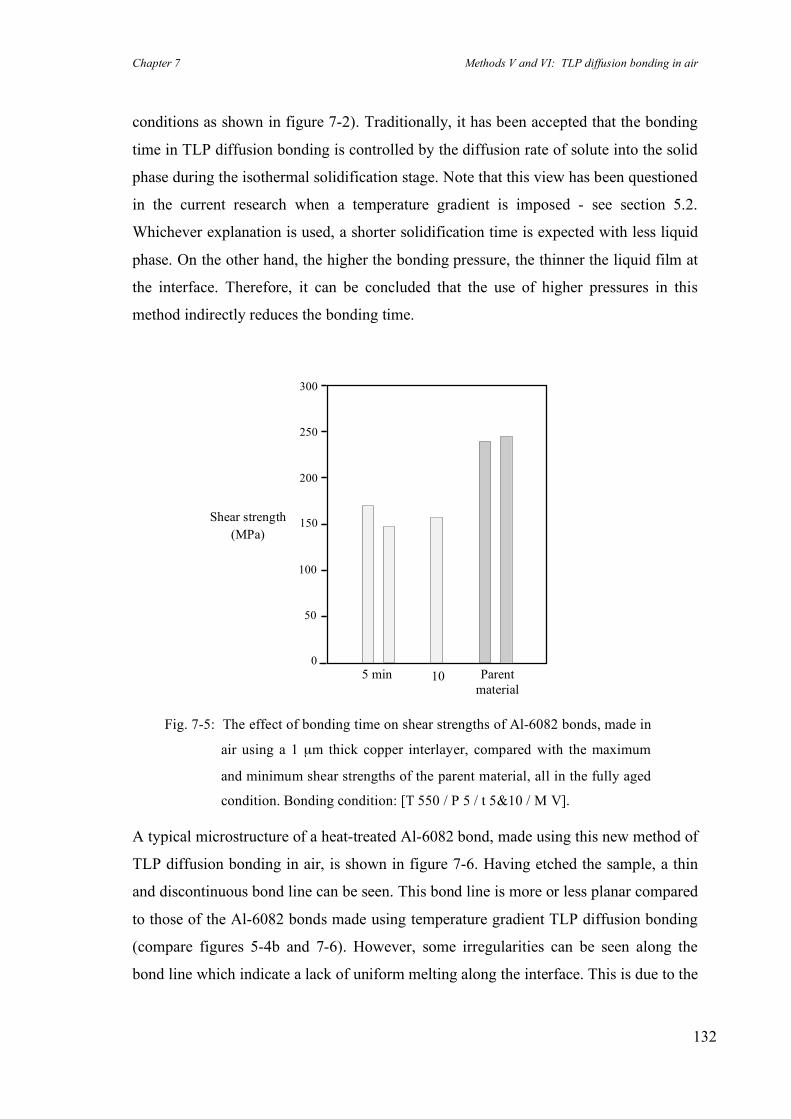
Chapter 7 Methods V and VI: TLP diffusion bonding in air
132
conditions as shown in figure 7-2). Traditionally, it has been accepted that the bonding
time in TLP diffusion bonding is controlled by the diffusion rate of solute into the solid
phase during the isothermal solidification stage. Note that this view has been questioned
in the current research when a temperature gradient is imposed - see section 5.2.
Whichever explanation is used, a shorter solidification time is expected with less liquid
phase. On the other hand, the higher the bonding pressure, the thinner the liquid film at
the interface. Therefore, it can be concluded that the use of higher pressures in this
method indirectly reduces the bonding time.
A typical microstructure of a heat-treated Al-6082 bond, made using this new method of
TLP diffusion bonding in air, is shown in figure 7-6. Having etched the sample, a thin
and discontinuous bond line can be seen. This bond line is more or less planar compared
to those of the Al-6082 bonds made using temperature gradient TLP diffusion bonding
(compare figures 5-4b and 7-6). However, some irregularities can be seen along the
bond line which indicate a lack of uniform melting along the interface. This is due to the
Fig. 7-5: The effect of bonding time on shear strengths of Al-6082 bonds, made in
air using a 1 µm thick copper interlayer, compared with the maximum
and minimum shear strengths of the parent material, all in the fully aged
condition. Bonding condition: [T 550 / P 5 / t 5&10 / M V].
Shear strength (MPa)
10 min
0
50
100
150
200
250
300
5 min
Parent
material
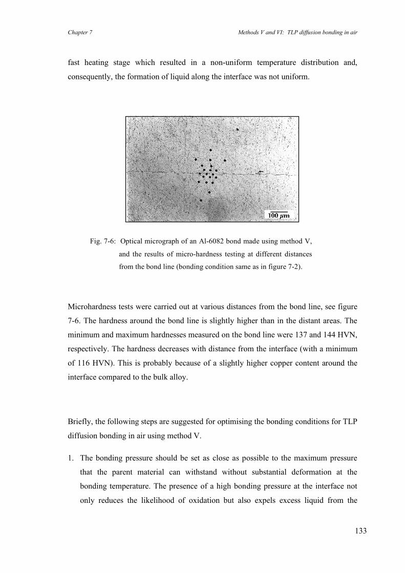
Chapter 7 Methods V and VI: TLP diffusion bonding in air
133
fast heating stage which resulted in a non-uniform temperature distribution and,
consequently, the formation of liquid along the interface was not uniform.
Microhardness tests were carried out at various distances from the bond line, see figure
7-6. The hardness around the bond line is slightly higher than in the distant areas. The
minimum and maximum hardnesses measured on the bond line were 137 and 144 HVN,
respectively. The hardness decreases with distance from the interface (with a minimum
of 116 HVN). This is probably because of a slightly higher copper content around the
interface compared to the bulk alloy.
Briefly, the following steps are suggested for optimising the bonding conditions for TLP
diffusion bonding in air using method V.
1. The bonding pressure should be set as close as possible to the maximum pressure
that the parent material can withstand without substantial deformation at the
bonding temperature. The presence of a high bonding pressure at the interface not
only reduces the likelihood of oxidation but also expels excess liquid from the
Fig. 7-6: Optical micrograph of an Al-6082 bond made using method V,
and the results of micro-hardness testing at different distances
from the bond line (bonding condition same as in figure 7-2).

Chapter 7 Methods V and VI: TLP diffusion bonding in air
134
interface during the bonding cycle. The effect of pressure on the thickness of the
liquid phase results in shorter bonding times, compared to bonds made using lower
bonding pressures.
2. The thickness of the interlayer should be chosen to provide sufficient liquid for
complete bond formation. Increasing the interlayer thickness provides better sealing
and also can result in slightly higher maximum bond strengths. However, thicker
interlayers result in greater expulsion of liquid during bonding which is not
desirable.
3. Having optimised the bonding pressure and interlayer thickness, the bonding time
can be determined by microstructural examination of a few bonds, made using
different bonding times, to ensure completion of the solidification stage, in order to
achieve a virtually homogenous microstructure at the bond line.
4. The important role of surface preparation should be emphasised. A lack of complete
contact between the faying surfaces and the interlayer leads to oxidation of the base
alloy and the interlayer, and consequently the bond strength decreases drastically.

Chapter 7 Methods V and VI: TLP diffusion bonding in air
135
7.3 Method VI: Temperature gradient TLP diffusion bonding
in air
TLP diffusion bonding under a temperature gradient (method IV) proved successful
and, using that method, reliable bonds with shear strengths as high as those of the parent
materials were produced. Using method IV, the evolution of the interface from planar to
a sinusoidal structure improved the bond strength because of the increased surface area
of the interface (see Chapter 5). Meanwhile, increasing the heating rate during TLP
diffusion bonding in air (method V) resulted in bonds with up to 90% shear strength of
that of the parent material. In light of these results, a sixth method, based on a
combination of methods IV and V, was developed to achieve better results than those
obtained using method V for bonding in air.
The sixth method relies on a fast heating stage to overcome the oxidation problem when
bonding in air, and also on the presence of a temperature gradient across the interface in
order to form a non-planar interface. However, imposing a temperature gradient during
the bonding process reduces the effective heating rate as a consequence of substantial
heat flux from the parts being joined into the heat sink (assuming the input power of the
heat source is constant). As mentioned before, a delay in the formation of the liquid
phase leads to oxidation of the interlayer and thickening of the oxide layer on the faying
surfaces. Therefore it is not desirable, when imposing a temperature gradient, to cause
an increase in the duration of the heating stage. In order to achieve a high heating rate
under a temperature gradient, either the heat input has to be increased, or the heat sink
should be modified to reduce the heat flux (see section 3.2.2 for experimental details).
An optimal combination of the specimen set-up and bonding conditions is required to
achieve high strength bonds, made in air.
Chapter 7 Methods V and VI: TLP diffusion bonding in air
136
7.3.1 Results of method VI and discussion
Initial experiments on temperature gradient TLP diffusion bonding in air (method VI),
revealed that the use of a specimen set-up similar to the one used for method IV
(temperature gradient TLP diffusion bonding) increased the duration of the heating
stage substantially. The faying surfaces and the interlayer were therefore exposed to air
for a long time before the formation of the liquid phase sealed the interface. Bonding
processes with heating stages longer than one minute (in air) resulted in poor bond
strengths, see figure 7-1.
Having designed a new specimen set-up for method VI, a few Al-6082 bonds were
made and shear tested. A maximum bond strength of 195 MPa (85% that of the parent
material) was achieved when using a 1 µm copper interlayer and bonding conditions of
[T 550 / P 6 / t 10 / M VI]. The minimum shear strength was 183 MPa (80% that of the
parent material). Although the maximum bond strength achieved in this method is
slightly lower than that achieved using method V (195 MPa compared to 206 MPa), it
seems that imposing a temperature gradient reduced the scatter in the results
considerably (from ±8% in method V to ±3% in method VI). These results are
promising and it seems that the presence of a temperature gradient was of benefit.
However more experiments are required to obtain conclusive results.
Precise control of the heating rate was found difficult when using this method. The
heating rate depends not only on the specimen set-up and the heat sink design but also
on the bonding pressure. The higher the bonding pressure, the better the thermal
conduction between the specimen and heat sink, leading to a slower temperature rise.
This lack of control of a crucial bonding parameter (the heating rate) resulted in
uncertainty when evaluating the effects of various other parameters. For example, the
use of a 7 µm copper interlayer resulted in poor bonds; though due to the variation in
the heating rate, it is not clear whether the increase in the thickness of the interlayer or
the lack of a sufficiently high heating rate is responsible.
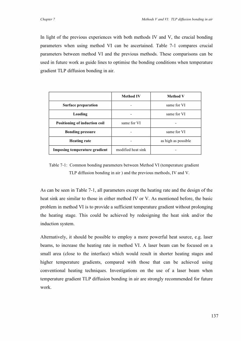
Chapter 7 Methods V and VI: TLP diffusion bonding in air
137
In light of the previous experiences with both methods IV and V, the crucial bonding
parameters when using method VI can be ascertained. Table 7-1 compares crucial
parameters between method VI and the previous methods. These comparisons can be
used in future work as guide lines to optimise the bonding conditions when temperature
gradient TLP diffusion bonding in air.
Method IV Method V
Surface preparation - same for VI
Loading - same for VI
Positioning of induction coil same for VI -
Bonding pressure - same for VI
Heating rate - as high as possible
Imposing temperature gradient modified heat sink -
Table 7-1: Common bonding parameters between Method VI (temperature gradient
TLP diffusion bonding in air ) and the previous methods, IV and V.
As can be seen in Table 7-1, all parameters except the heating rate and the design of the
heat sink are similar to those in either method IV or V. As mentioned before, the basic
problem in method VI is to provide a sufficient temperature gradient without prolonging
the heating stage. This could be achieved by redesigning the heat sink and/or the
induction system.
Alternatively, it should be possible to employ a more powerful heat source, e.g. laser
beams, to increase the heating rate in method VI. A laser beam can be focused on a
small area (close to the interface) which would result in shorter heating stages and
higher temperature gradients, compared with those that can be achieved using
conventional heating techniques. Investigations on the use of a laser beam when
temperature gradient TLP diffusion bonding in air are strongly recommended for future
work.
Chapter 7 Methods V and VI: TLP diffusion bonding in air
138
7.4 Summary
Method V: High heating rate TLP diffusion bonding in air
The new method for TLP diffusion bonding of aluminium-based materials in air has
proved successful, and bonds with shear strengths comparable with that of the parent
material have been made (up to 90% that of the parent material). This method relies on
a rapid heating stage and also on the preparation of flat faying surfaces in order to
overcome potential oxidation problems associated with bonding in air.
It should be emphasised that the surface preparation method and the bonding set-up
used in this work should be regarded as guide lines since they were developed for
laboratory purposes. Other approaches can be adopted. The following techniques are
recommended to improve the results and to make the process more suitable for
commercial exploitation.
1. The heating rate could be increased by improving the induction system or using
other heating sources, e.g. a laser beam. The development of this approach is in
progress.
2. Surface preparation could be improved by high precision grinding, preferably
followed by a lapping process.
3. The loading arrangement should be designed according to the shape and size of the
parts to be joined.
The bonding temperature, using this method and a copper interlayer, is close to the
solution-treatment temperature of most aluminium alloys (i.e. ~540°C). In contrast to
bonding in vacuum, it is feasible with this method to quench parts directly from the
bonding temperature, so they are effectively solution treated. The parts can
subsequently be aged to improve properties.
Chapter 7 Methods V and VI: TLP diffusion bonding in air
139
This method is expected to be applicable to the diffusion bonding in air of materials
other than aluminium alloys.
Method VI: Temperature gradient TLP diffusion bonding in air
Temperature gradient TLP diffusion bonding in air (method VI) was developed to
improve the reliability and strength of the aluminium bonds made in air. This new
method takes advantage of inducing a temperature gradient (as in method IV) to reliably
produce high strength joints, and at the same time, employs a fast heating stage (as in
method V) to overcome the oxidation problems associated with bonding in air.
The results of preliminary experiments on joining Al-6082 alloy, using this sixth
method, are promising. Compared to the results achieved using method V, the scatter in
results was reduced when using method VI and similar bonding conditions (i.e.
pressure, time, temperature and interlayer). Using this new method, bonds with shear
strengths in the range of 183 to 195 MPa were produced. It seems the reliability of the
bonds are improved by using method VI, even though the maximum bond strength was
slightly lower than that of the bonds made using method V.
However, attaining a sufficiently high heating rate, and also precise control of this
crucial factor, proved difficult; imposing a temperature gradient decreases the heating
rate drastically (for a particular heating system and heat sink). The reduction and
variation in the heating rate, when bonding in air, resulted in unfavourable scatter in the
bond strengths. Therefore, the design of the heating system and heat sink become
important factors when attempting to impose a sufficient temperature gradient, while
maintaining a high enough heating rate.
Further investigation of this method, particularly on the use of other heat sources e.g.
laser beams, is strongly recommended for future work.
Chapter 8 Conclusions and proposal for future work
140
Chapter 8
8. Conclusions and proposal for future work
Six new methods for TLP diffusion bonding of aluminium-based materials have been
developed during the current work. A comprehensive analytical model for the fourth
method has been also proposed and verified experimentally.
8.1 Experimental results
Method I
The first method (isostatic TLP diffusion bonding) relies on a simultaneous combination
of isostatic compression and TLP diffusion bonding process in order to increase the
bond strength. The use of this method for joining Al-8090/SiC composite proved
successful. Bonds with shear strengths up to 221 MPa (85% that of the parent material)
were produced using 3 µm thickness copper interlayers (the maximum shear strength
obtained from bonds made using conventional TLP diffusion bonding was 105 MPa).
Method II
Method II consists of low pressure TLP diffusion bonding followed by solid-state
diffusion bonding under isostatic pressure in air. The highest and lowest bond strengths
for the Al-359/SiC bonds, using this method and a 7 µm thickness copper interlayer,
were 242 and 212 MPa which are 92 and 80% of the strength of the parent material in
the fully aged condition. These values are far beyond the highest diffusion bond
strengths that have been reported for aluminium metal matrix composites to date.
Chapter 8 Conclusions and proposal for future work
141
The shear test results and examination of the microstructures showed that the thickness
of the interlayer has a key role when TLP diffusion bonding Al-MMCs. The use of 1
µm thickness copper interlayers resulted in low bond strengths. On the other hand, the
use of a thick interlayer (e.g. 12.5 µm) caused unfavourable agglomeration of the
reinforcement particles about the bond line. Thicknesses of between 3 and 7 µm
resulted in excellent strengths but the thickness of the interlayer should be optimised for
each alloy.
Method III
The third method (method III) was developed to fabricate intricate components with
minimal plastic deformation during the bonding process (particularly for superplastic
materials with very low yielding strengths at the bonding temperature). In this method,
low pressure TLP diffusion bonding is followed by hot isostatic pressing (HIP) without
encapsulation. In contrast to conventional "HIP bonding" the complexity associated
with encapsulation is avoided. Thus components with complicated shapes can be
produced. The highest bond strength achieved for un-reinforced Al-6082, using a 7 µm
thickness copper interlayer, was 200 MPa (89% of the shear strength of parent
material).
Method IV
Imposing a temperature gradient when TLP diffusion bonding, as a novel approach for
joining aluminium alloys, resulted in reliable bonds with shear strengths as high as
those of the parent materials. The average shear strengths of the parent alloy and the Al-
6082 bonds, made using copper interlayers with a thickness of 1.5 µm, were 250 MPa
(with a scatter of less than ±2%). The shear strength of a dissimilar Al alloy and Al-
MMC joint was comparable to that of the Al alloy, which confirms the potential of this
method for the joining of dissimilar materials. It is assumed that the evolution of the
interface from planar to a sinusoidal/cellular structure, as the result of imposing a
temperature gradient, improves the bond strength because of the increased surface area
of the interface.
Chapter 8 Conclusions and proposal for future work
142
The kinetics of this method rely on the diffusion of solute in the liquid phase. Therefore,
the bonding times, using this method, are much shorter than for conventional TLP
diffusion bonding. The analytical solution proposed in Chapter 6 for the new method is
in good agreement with the experimental results.
It is believed that the model developed is also applicable to conventional TLP diffusion
bonding. The approach outlined above may provide a more rigorous description of TLP
diffusion bonding when, nominally, a temperature gradient is not imposed. In practice, a
small difference is likely to exist between the temperatures at the two solid/liquid
interfaces whenever TLP diffusion bonding is attempted. This is a completely new way
of describing the process and is more consistent with the results that are achieved.
Finally, it is believed that temperature gradient TLP diffusion bonding is applicable to a
wide range of aluminium-based alloys and composites. It is also likely to be of benefit
when joining other materials and metallic alloys, particularly those with stable oxide
films.
Method V
This new method for the TLP diffusion bonding of aluminium-based materials in air has
proved successful, and Al-6082 bonds with shear strengths comparable with that of the
parent material have been made (up to 90% that of the parent material). This method
relies on a rapid heating stage and also on the preparation of flat faying surfaces in order
to overcome potential oxidation problems associated with bonding in air.
In contrast to bonding in vacuum, it is feasible with this method to quench parts directly
from the bonding temperature, so they are effectively solution treated. The parts can
subsequently be aged to improve properties.
This method is expected to be applicable to the diffusion bonding in air of materials
other than aluminium alloys.
Method VI
Chapter 8 Conclusions and proposal for future work
143
Temperature gradient TLP diffusion bonding in air (method VI) was developed to
improve the reliability and strength of the aluminium bonds made in air. This new
method takes advantage of inducing a temperature gradient (as in method IV) and at the
same time, employs a fast heating stage (as in method V) to overcome the oxidation
problems associated with bonding in air.
When using this method and similar bonding conditions as in method V, Al-6082 bonds
with shear strengths in the range of 183 to 195 MPa were produced. The scatter in
results was reduced, even though the maximum bond strength was slightly lower than
that of the bonds made using method V.
The design of the heating system and heat sink are important factors when attempting to
impose a sufficient temperature gradient while maintaining a high enough heating rate -
see below for the suggestions for future work on this method.
Al-Li (UL-40) bonds
The aluminium-lithium alloy (UL-40) showed quite different bonding characteristics,
probably because of the high percentage of lithium (4 wt.%) which forms a very stable
surface layer. The maximum bond strength achieved, using method I and a copper
interlayer of 12.5 µm thickness, was 155 MPa.
Method IV (temperature gradient TLP diffusion bonding) was used to break up the
normally continuous bond line of this alloy. Imposing a temperature gradient has a
dramatic effect on the microstructure of the UL-40 bond line, showing that the stable
interface is disrupted. Although no assessment of mechanical properties has been
carried out on the UL-40 bonds, it is expected that the use of the new method may lead
to higher bond strengths than the previously reported values.
Summary:
Chapter 8 Conclusions and proposal for future work
144
In figure 8-1, the maximum bond strengths achieved using these new methods are
compared with the average shear strength of the parent material given the same heat
treatment.
• The use of method IV (temperature gradient TLP diffusion bonding) resulted in the
highest bond strength, with excellent reliability, compared to the other five methods.
Note that the maximum bond strength is slightly higher than the average shear strength
of the parent material.
• Two new methods for TLP diffusion bonding in air (methods V and VI) are capable of
producing bonds with shear strengths up to 90% that of the parent materials. Although
these results are not as good as those obtained using method IV, the practicality and
feasibility of these methods are definitely of interest since a vacuum system is not
required.
• Despite the satisfactory results of the methods mentioned above, the methods based on
applying isostatic pressure, particularly method III, remain an attractive solution for
TLP diffusion bonding aluminium alloys and composites which have very low yield
strengths at bonding temperatures. The use of the other methods can result in
undesirable plastic deformation during the bonding process.
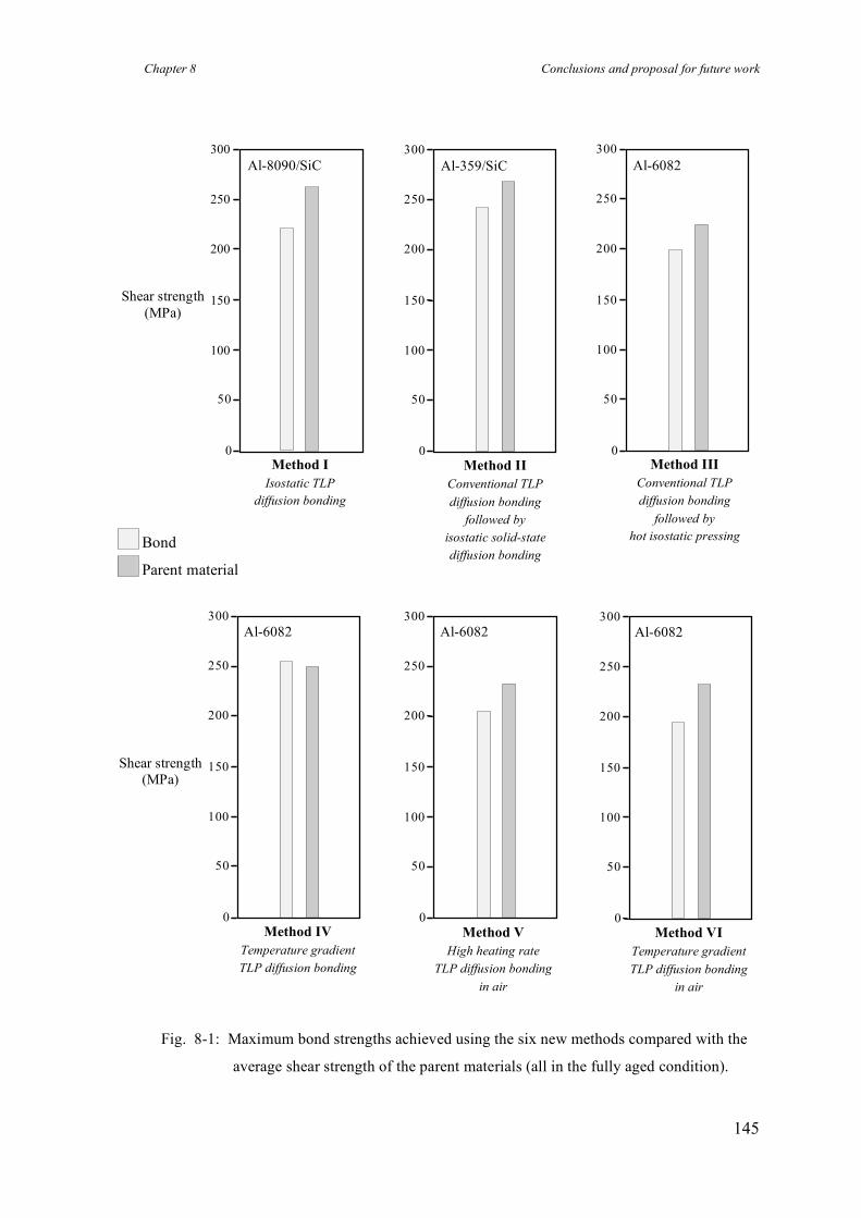
Chapter 8 Conclusions and proposal for future work
145
Fig. 8-1: Maximum bond strengths achieved using the six new methods compared with the
average shear strength of the parent materials (all in the fully aged condition).
Shear strength (MPa)
0
50
100
150
200
250
300 Al-6082
Method IV Temperature gradient TLP diffusion bonding
0
50
100
150
200
250
300 Al-6082
Method V High heating rate
TLP diffusion bonding in air
0
50
100
150
200
250
300 Al-6082
Method VI Temperature gradient TLP diffusion bonding
in air
0
50
100
150
200
250
300
Method II Conventional TLP diffusion bonding
followed by isostatic solid-state diffusion bonding
Al-359/SiC
Shear strength (MPa)
0
50
100
150
200
250
300
Method I Isostatic TLP
diffusion bonding
Al-8090/SiC
0
50
100
150
200
250
300
Method III Conventional TLP diffusion bonding
followed by hot isostatic pressing
Al-6082
Bond
Parent material
Chapter 8 Conclusions and proposal for future work
146
8.2 Modelling of method IV
Temperature gradient TLP diffusion bonding (method IV) is a new approach which
cannot be theoretically analysed using the existing models for conventional TLP
diffusion bonding. Therefore a new analytical model was developed to predict bonding
times and interface displacements when using this method.
This new model provides precise solutions for predicting bonding times and interface
displacement when TLP diffusion bonding under a temperature gradient. These
solutions were simplified, using a mass balance approach and by applying some
approximations, to provide less complicated solutions than the precise ones. The precise
and approximate solutions are in excellent agreement for the range of bonding
parameters likely to be used when TLP diffusion bonding.
Using a simple Al-Cu system, the accuracy of the analytical solutions were
experimentally verified. The analytical solutions are in good agreement with the
experimental results for boundary displacement and bonding time. Also, the
experiments showed that bonding pressure has a drastic effect on the actual width of the
liquid phase in TLP diffusion bonding. This has not been taken into account in previous
analyses of the TLP diffusion bonding processes.
It is believed that the model is applicable to conventional TLP diffusion bonding even
when, nominally, a temperature gradient is not imposed as a small temperature
difference is likely to exist between the two solid/liquid interfaces. This provides a
completely new way to describe and rigorously model TLP diffusion bonding,
overcoming some of the assumptions required in previous models.

Chapter 8 Conclusions and proposal for future work
147
8.3 Future work
In light of the results achieved during the current work, the following topics are
suggested for future work.
• Further work on the scientific aspects and modelling of temperature gradient
TLP diffusion bonding (method IV)
The idea of introducing a temperature gradient when TLP diffusion bonding is a new
approach for joining aluminium-based materials. In contrast to conventional
explanations of TLP diffusion bonding which have relied on the diffusion of solute in
the solid phase, the new approach is based on the diffusion of solute in the liquid phase.
Further study of theoretical aspects (e.g. nature of solute rejection) is required in order
to provide a better understanding of the new approach, and of the magnitude of the
temperature gradients that can be used successfully.
This new approach may also provide a more rigorous and successful description of
conventional TLP diffusion bonding when, nominally, a temperature gradient is not
imposed. In addition, other isothermal processes associated with transient liquid phases,
e.g. liquid phase sintering, may be reinvestigated using this different point of view.
According to the analytical solution proposed in this work, the bonding time can be
controlled by the magnitude of the temperature gradient. The proposed analytical model
now requires further development so that the bonding conditions can be optimised for
different materials. For example, the effects of the temperature gradient on the
microstructures of bond lines should be included in the analytical model. The model
also needs further verification by comparing additional experimental results with
theoretical values.
Chapter 8 Conclusions and proposal for future work
148
• Further expansion and application of method IV
Using temperature gradient TLP diffusion bonding (method IV), the microstructure of
the bond line and the bonding time can be controlled favourably. The current work has
examined several aluminium alloys and composites, and bonds could be made reliably
with shear strengths as high as those of the corresponding parent materials. Further
investigation is required to generalise the use of this new approach in the diffusion
bonding of advanced materials which cannot be joined using conventional methods.
This method should be of benefit when joining superalloys, particularly nickel-based
alloys, as well as intermetallic and dissimilar materials.
• Further expansion and application of method VI
The preliminary results of the sixth method (Temperature gradient TLP diffusion
bonding in air) were promising and bonds with shear strengths of 85% of that of the
parent material (Al-6082) were produced. However, precise control of the duration of
the heating stage was found difficult. Improvements to the design of the heat sink and
heating source are required to achieve a high heating rate while a temperature gradient
is imposed across the interface. Investigation of more powerful heating sources, e.g.
laser beams, is recommended for future work.
• Further expansion and application of method III
Method III (Low pressure transient liquid phase diffusion bonding followed by hot
isostatic pressing without encapsulation) allows the fabrication of intricate parts from
superplastic materials with virtually no deformation during the bonding process, and so
dimensional tolerances are preserved. However, this method needs to be further
evaluated and developed. The first stage could be carried out using a temperature
gradient in order to achieve a non-planar interface. Consequently, the sealing of the
bond line, required for the second stage (HIP without encapsulation), is expected to be
improved. Further work is necessary to optimise the bonding conditions in order to
improve the reliability of the process.
Chapter 8 Conclusions and proposal for future work
149
• The use of alloy interlayers rather than pure copper, in order to decrease the
bonding temperature when TLP diffusion bonding of aluminium alloys
The bonding temperature for TLP diffusion bonding of aluminium-based materials,
using copper interlayers, is quite high (~550°C). Such a high temperature process can be
associated with unfavourable phase transformations in some parent alloys, and also
between reinforcement and the matrix when bonding composite materials. Therefore it
will be beneficial to lower the bonding temperature (ideally < 450°C). This may be
achieved using an alloy interlayer which forms a liquid phase with aluminium at lower
bonding temperatures, e.g. using the Zn/Cu/Al ternary system with eutectic/peritectic
reactions. Investigation of different alloy interlayers needs to be undertaken.
• Development of method IV for joining dissimilar materials
The joining of dissimilar materials has been of interest to combine alloys or composites
with different mechanical-physical properties in order to optimise the exploitation of
engineering materials. For example, the wear resistance of an aluminium alloy can be
improved by up to 30 times when an aluminium matrix composite (with SiC particles)
is used in components which are subjected to mechanical abrasion. The preliminary
experiments to date have shown that temperature gradient TLP diffusion bonding is
capable of producing strong bonds between aluminium-based alloys and composites.
Further work is required to extend the application of the method to join dissimilar
materials, e.g. joining steel to aluminium.
• Use of electroplating for deposition of interlayers in TLP diffusion bonding
Deposition of copper by electroplating techniques, rather than using foils or sputter
coated interlayers, for TLP diffusion bonding of aluminium-based materials is also of
interest. If this method is successful, then the scope for TLP diffusion bonding of these
materials will be extended considerably, including the possibility of commercial
exploitation, e.g. in the fabrication of honeycomb structures by the selective deposition
of copper on the bonding areas of aluminium sheets.
References
150
References
Barta I.M. (1964), “Low temperature diffusion bonding of aluminium alloys”, Welding journal
Research Supplement, June, 241s-247s, June.
Bienvenu Y. and Koutny J.L. (1990), “Diffusion bonding of thin aluminium foils”, Proc. Conf.
Diffusion Bonding 2, Cranfield Institute of Technology, Cranfield, UK, 111-118, ed.
Stephenson D.J, Amsterdam, Elsevier.
Bushby R.S. and Scott V.D. (1993), “Liquid phase bonding of aluminium and
aluminium/Nicalon composite using copper interlayers”, Materials Science and.
Technology, Vol. 9, 417-423.
Bushby R.S. and Scott V.D. (1995a), “Liquid phase bonding of aluminium and
aluminium/Nicalon composite using interlayers of Cu-Ag alloy”, Materials Science and.
Technology, Vol. 11, 643-649.
Bushby R.S. and Scott V.D. (1995b), “Joining of particulate silicon carbide reinforced 2124
aluminium alloy by diffusion bonding”, Materials Science and. Technology, Vol. 11,
753-758.
Cailler M., Debbouz O., Dannawi M. and Latouche T. (1991), “Mechanical characterisation by
dynamical tensile loading of 2017 aluminium alloy joints welded by diffusion bonding”,
Journal of Materials Science, Vol. 26, 4997-5003.
Church S., Day J. and Wild B. (1996), “Diffusion bonding of metals and alloys”, Materials
World, Vol. 4, No. 7, 385-386.
Cline C.L. (1966), “An analytical and experimental study of diffusion bonding”, Welding
Journal Research Supplement, November, 481s-489s.
Crank J. (1975), ‘The mathematics of diffusion’, Clarendon Press, Oxford.
References
151
Crank J. (1984), ‘Free and moving boundary problems’, Clarendon Press, Oxford.
Debbouz O. and Navai F. (1997), “Mechanical characterisation by dynamical tensile loading of
2017 aluminium alloy joints welded by diffusion bonding. New results and SEM
observations of the failure surfaces”, Journal of Materials Science, Vol. 32, 475-482.
Derby B. and Wallach E.R. (1982), “Theoretical model for diffusion bonding”, Metal Science,
Vol. 16, 49-56.
Derby B. and Wallach E.R. (1984), “Diffusion bonding: development of theoretical model”,
Metal Science, Vol. 18, 427-431.
Derby B. (1990), “Diffusion Bonding”, in ‘Joining of Ceramics’, ed. Nicholas M.G., Chapman
and Hall.
Dray A.E. (1985), “Diffusion bonding of aluminium”, Ph.D. thesis, University of Cambridge,
UK.
Dunford D.V. and Partridge P.G. (1987), “The peel strengths of diffusion bonded joints
between clad Al-alloy sheets”, Journal of Materials Science, Vol. 22, 1790-1798.
Dunford D.V., Partridge P.G. and Gilmore C.J. (1990), “Diffusion bonding of Al-Li alloys
Proc. Conf. Diffusion Bonding 2, Cranfield Institute of Technology, Cranfield, UK, 130-
143, ed. Stephenson D.J, Amsterdam, Elsevier.
Dunford D.V. and Partridge P.G. (1990), “Strength and fracture behaviour of diffusion-bonded
joints in Al-Li (8990) alloy, Part 1: Shear strength”, Journal of Materials Science, Vol.
25, 4957-4964.
Dunford D.V. and Partridge P.G. (1991), “Strength and fracture behaviour of diffusion-bonded
joints in Al-Li (8990) alloy, Part 2: Fracture behaviour”, Journal of Materials Science,
Vol. 26, 2625-2629.
Dunford D.V. and Partridge P.G. (1992), “Diffusion bonding of Al-Li alloys”, Materials
Science and Technology, Vol. 8, 385-398.
References
152
Ellis M.B.D. (1992), “Solid-state joining of aluminium alloys and aluminium-based metal
matrix composites (MMC)”, in ‘Aluminium Industry’, Vol. 11, No. 5, 27-30.
Ellis M.B.D., Gittos M.F. and Threadgill P.L. (1994), “Joining aluminium based metal matrix
composites”, Materials World, Vol. 2, No. 8, 415-417.
Ellis M.B.D. (1996), “Joining of aluminium based metal matrix composites”, International
Materials Review, Vol. 41, No. 2, 41-58.
Enjo T., Ikeuchi K. and Akikawa N. (1978), “Study of microscopic process of diffusion
welding by electric resistance measurement and transmission electron microscope”,
Transaction of JWRI, Vol. 7, No. 2, 97-100.
Enjo T. and Ikeuchi K. (1984), “Diffusion welding of Al-Cu-Mg series 2017 alloy”,
Transactions of JWRI, Vol. 13, No. 2, 63-68.
Escalera M.D., Urena A. and Gomez de Salazar J.M. (1997), “Solid state diffusion bonding of
AA6061 matrix composites reinforced with alumina particles”, ASM Proc. Conf.
Welding and Joining Science and Technology, Madrid, Spain, 380-389.
Garmong G., Paton N.E. and Argon A.S. (1975), “Attainment of full interfacial contact during
diffusion bonding”, Metallurgical Transactions A, Vol. 6A, 1269-1279.
Gilmore C.J., Dunford D.V. and Partridge P.G. (1991), “Microstructure of diffusion-bonded
joints in Al-Li 8090 alloy”, Journal of Materials Science, Vol. 26, 3119-3124.
Gomez de Salazar J.M., Urena A. and Fernandez M.I. (1997), “Transient liquid phase diffusion
bonding in aluminium-based composites”, ASM Proc. Conf. Welding and Joining
Science and Technology, Madrid, Spain, 397-406.
Harvey J., Partridge P.G. and Snooke C.L. (1985), “Diffusion bonding and testing of Al-alloy
lap shear test pieces”, Journal of Materials Science, Vol. 20, 1009-1014.
References
153
Harvey J., Partridge P.G. and Lurshay A.M. (1986), “Factors affecting the shear strength of
solid state diffusion bonds between silver-coated clad Al-Zn-Mg alloy (Aluminium alloy
7010)”, Materials Science and Engineering, Vol. 79, 191-199.
Hill A. and Wallach E.R. (1989), “Modelling solid-state diffusion bonding”, Acta Metallurgica,
Vol. 37, No. 9, 2425-2437.
Houldcroft P.T. (1977), ‘Welding Process Technology’, Cambridge University Press.
Ikeuchi K. and Asano K. (1993), “Development of intermediate layer for diffusion bonding of
continuous alumina fibre reinforced aluminium matrix composite”, Transactions of
JWRI, Vol. 22, No. 1, 77-84.
Kazakov N.F(1985, English version), ‘Diffusion Bonding of Materials’, Pergamon Press.
Knight C.A. (1962), “Curved growth of ice on surfaces”, Journal of Applied of physics, Vol. 33,
No. 5, 1808-1815.
Kotani K., Ikeuchi K. and Matsuda F. (1996a), “Interfacial oxides in diffusion-bonded joints of
Al-Mg alloys by TEM”, Proc. The 6th International Symposium of Japan Welding
Society, Nagoya, Japan, November, 95-100, Ed. Ushio M.
Kotani K., Ikeuchi K. and Matsuda F. (1996b), “Effects of interfacial phases on joint strength of
diffusion-bonded aluminium alloys”, Quarterly Journal of the Japan Welding Society,
Vol. 14, No. 2, 382-388 (in Japanese).
Kuriyama K. (1992), “Joining of Composites”, Ph.D. Thesis, University of Cambridge.
Lesoult G. (1976), Centre for Joining of Materials Report, Carnegie Mellon University,
Pittsburgh, PA, USA.
Livesey D.W. and Ridley N. (1990), “Diffusion bonding of superplastic aluminium alloys using
a transient liquid phase interlayer (zinc)”, Proc. Conf. Diffusion Bonding 2, Cranfield
Institute of Technology, Cranfield, UK, 83-100, ed. Stephenson D.J, Amsterdam,
Elsevier.
References
154
Lloyd D.J. (1994), “Particle reinforced aluminium and magnesium matrix composites”,
International Materials Review, Vol. 39, No. 1, 1-23.
MacDonald W.D. and Eagar T.W. (1992), “Transient liquid phase bonding processes”, in ‘The
Metal Science of Joining’ 93-100, ed. Cieslak M.J. et al., The Minerals, Metals &
Materials Society.
Maddrell E.R. (1989), “Diffusion bonding of aluminium alloys”, Ph.D. Thesis, University of
Cambridge.
Maddrell E.R., Ricks R.A. and Wallach E.R. (1989), “Diffusion bonding of aluminium alloys
containing lithium and magnesium”, Proc. Conf. Aluminium-Lithium 5, Williamsburg,
Virginia, USA, 451-460, ed. Sanders Jnr. T.H. and Starke Jnr. E.A., MCEP Ltd.
Birmingham, UK.
Maddrell E.R. and Wallach E.R. (1990), “Diffusion welding of aluminium-lithium alloys”, Proc
Conf. Recent Trends in Welding Science & Technology, 541-545, ed. David S.A. and
Vitek V.M., ASM International.
Materials Progress (1997), “Aluminium composite reduces cost, improves performance”,
Advanced Materials & Processes, ASM International, Vol. 152, No. 4, 7.
Morley R.A. and Caruso J. (1980), “Diffusion welding of 390 aluminium alloy hydraulic valve
bodies”, Welding Journal, August, 29-34.
Nakagawa H., Lee C.H. and North T.H. (1991), “Modelling of base metal dissolution behaviour
during transient liquid-phase brazing”, Metallurgical Transactions A, Vol. 22A, 543-555.
Nicholas N.H., Nichting R.A., Edwards G.R. and Olson D.L. (1990), “The influence of surface
topography on low temperature solid state bonding”, Proc. Conf. Recent Trends in
Welding Science & Technology, 547-550, ed. David S.A. and Vitek V.M., ASM
International.
References
155
Niemann J.T. and Garrett R.A. (1974a), “Eutectic bonding of boron-aluminium structural
components (Part 1)”, Welding Journal Research supplement, April, 175s-184s.
Niemann J.T. and Garrett R.A. (1974b), “Eutectic bonding of boron-aluminium structural
components (Part 2)”, Welding Journal Research supplement, August, 351s-360s.
Osawa T. (1995), “Changes in the interface structure and strength of the diffusion brazed joints
of Al-Si system alloy castings”, Welding Journal Research Supplement, 206s-212s.
Partridge P.G. and Dunford D.V. (1991), “The role of interlayer in diffusion bonded joints in
metal-matrix composites”, Journal of Materials Science, Vol. 26, 2255-2258.
Peel C., Robertson J. and Tarrant A. (1995), “Have metal matrix composites proved their
worth?”, Materials World, Vol. 3, No. 1, 8-9.
Pfann W.G. (1955), “Temperature gradient zone melting”, Transactions AIME, Vol. 203, 961-
964.
Pilling J. and Ridley N. (1987), “Solid state bonding of superplastic AA 7475” Materials
Science and Technology, Vol. 3, 353-359.
Ricks R.A., Winkler P.J., Stoklossa H. and Grimes R. (1989), “Transient liquid phase bonding
of aluminium-lithium base alloy AA 8090 using roll-clad Zn based interlayers”, Proc.
Conf. Aluminium-Lithium 5, Williamsburg, Virginia, USA, 441-449, ed. Sanders Jnr.
T.H. and Starke Jnr. E.A., MCEP Ltd. Birmingham, UK.
Ricks R.A., Mahon G.J., Parson N.C., Heinrich T. and Winkler P.J. (1990), “Development of
diffusion bonding techniques for Al-Li base alloy AA 8090”, Proc. Conf. Diffusion
Bonding 2, Cranfield Institute of Technology, Cranfield, UK, 69-82, ed. Stephenson D.J,
Amsterdam, Elsevier.
References
156
Sabathier V., Edwards G.R. and Cross C.E. (1994), “Kinetics study of low-temperature
transient liquid phase joining of an aluminium-SiC composite”, Metallurgical and
Materials Transactions A, Vol. 25A, 2705-2714.
Scamans G.M. and Butler E.P. (1975), “In situ observations of crystalline oxide formation
during aluminium and aluminium alloy oxidation”, Metallurgical Transactions A, Vol.
6A, 2055-2063.
Sekerka R.F., Jeanfiles C.F. and Heckel R.W. (1975), in “Lectures on the theory of phase
transformations”, ed. Aaronson, New York, AIME, 117-169.
Sekerka R.F., Jeanfiles C.F. and Heckel R.W. (1975), Technical Report NO. 3, Carnegie
Mellon University, Pittsburgh, PA, USA.
Singer C., Holmyard E.J., Hall A.R. and Williams T.I. (1958), ‘A History of Technology’,
Oxford University Press.
Staley J.T., Liu J. and Hunt Jr. W.H. (1997), “Aluminium alloys for aerostructures”, Advanced
Materials & Processes, Vol. 152, No. 4, 17-20.
Takahashi Y., Ueno F. and Nishiguchi K. (1988), “A numerical analysis of the void-shrinkage
process controlled by surface-diffusion”, Acta Metallurgica., Vol. 36, No. 11, 3007-3018.
Takahashi Y., Takahashi K. and Nishiguchi K. (1991), “A numerical analysis of the void
shrinkage processes controlled by coupled surface and interface diffusion”, Acta
Metallurgica. et Materialia, Vol. 39, No. 12, 3199-3216.
Takahashi Y. and Inoue K. (1992), “Recent void shrinkage models and their applicability to
diffusion bonding”, Materials Science and Technology, Vol. 8, 953-964.
Takahashi Y. and Tanimoto M. (1995a), “Effect of surface asperity on interfacial contact
process controlled by power law creep-numerical study of viscoplastic adhering process”,
Transactions of the ASME, Vol. 117, 330-335.
References
157
Takahashi Y. and Tanimoto M. (1995b), “Experimental study of interfacial contacting process
controlled by power law creep”, Transactions of the ASME, Vol. 117, 336-340.
Tensi H.M., Wittmann M., Friedrich H.E. and Schmidt J.J. (1989), “Diffusion bonding of high
strength aircraft and aerospace aluminium alloys”, Proc. Conf. Light alloys for aerospace
applications, Las Vegas, USA, 465-479, ed. Lee E.W. et al., The Minerals, Metals &
Materials Society.
Tensi H.M. and Wittmann M. (1990), “Influence of surface preparation on the diffusion
welding of high strength aluminium alloys”, Proc. Conf. Diffusion Bonding 2, Cranfield
Institute of Technology, Cranfield, UK, 101-110, ed. Stephenson D.J, Amsterdam,
Elsevier.
Tiller W.A. (1963), “Migration of a liquid zone through a solid: part I”, Journal of Applied of
physics, Vol. 34, No. 9, 2757-2762.
Tuah-poku I., Dollar M. and Massalski T.B. (1988), “A study of the transient liquid phase
bonding process applied to a Ag/Cu/Ag sandwich joint”, Metallurgical Transactions A,
Vol. 19A, 675-686.
Urena A. and Dunkerton S.B. (1989), “Diffusion bonding of an aluminium-lithium alloy
(AA8090)” Report No. 403, 421-456, The Welding Institute, Abington, UK.
Urena A., Gomez de Salazar J. M. and Escalera M. D. (1995), “Diffusion bonding of
discontinuously reinforced SiC/Al matrix composites: The role of interlayers”, in metal
matrix composite; Key Engineering Materials, Vol. 104-107, 523-540, ed. Newaz G.M.,
Trans Tech. Publications Ltd. Switzerland.
Urena A., Gomez de Salazar J.M., Quinones J. and Martin J.J. (1996a), “TEM characterisation
of diffusion bonding of superplastic 8090 Al-Li alloy”, Scripta Materialia, Vol. 34, No.
4, 617-623.
Urena A., Gomez de Salazar J.M. and Escalera M.D.(1996b), “Diffusion bonding of an
aluminium-copper alloy reinforced with silicon carbide particles (AA2014/SiC/13p)
using metallic interlayers”, Scripta Materialia, Vol. 35, No. 11, 1285-1293.
References
158
Voller V.R. and Sundarraj S. (1993), “Modelling of microsegregation”, Materials Science and
Technology, Vol. 9, 474-481.
Wallach E.R. (1988), “Solid-state diffusion bonding of metals”, Transactions of. JWRI, Vol. 17,
No. 1, 135-148.
Welding Handbook (1976), 7th ed., Vol. 1, AWS.
Whitman W.G. (1926), “Elimination of salt from sea-water ice”, American Journal of Science,
5th series, Vol. XI, No. 62, 126-132.
Yokota T., Otsuka M., Haseyama T., Ueki T. and Tokisue H. (1997), “Solid phase welding of
alloy AA6061 and SiCp reinforced alloy AA6061 at intermediate temperature”, Materials
Science Forum, Vol. 242, 225-230.
Zhai Y. and North T.H. (1997), “Counteracting particulate segregation during transient liquid-
phase bonding of MMC-MMC and Al2O3-MMC joints”, Journal of Materials Science,
Vol. 32, 5571-5575.
Zhou Y. (1994), “Numerical modelling of process kinetics during TLP bonding and other
diffusion-controlled processes.”, Ph.D. Thesis, University of Toronto.
Zhou Y, Gale W.F. and North T.H. (1995), “Modelling of transient liquid phase bonding”,
International Materials Reviews, Vol. 40, No. 5, 181-196.