differential discrimination technique for incoherent doppler lidar to measure atmospheric wind and...
TRANSCRIPT
OPTICAL REVIEW Vol. 3, No. I (1996) 47-52
Differential Discrimination Technique for Incoherent Doppler Lidar to Measure Atmospheric Wind and Backscatter Ratio Zhaoyan LlU and Takao KOBAYASHI Department of Electrical and Electronics Engineering, Faculty of Engineering, Fukui University, 3-9-1, Bunkyo, Fukui,
910 Japan
(Received August 17, 1995; Accepted October 11, 1995)
A new incoherent Doppler lidar scheme is proposed using a high resolution Mach-Zehnder interferometer discriminator with sinusoidal transmission Lunctions. A two-channel differential discrimination technique is developed which provides high sensitive velocity measurement. The aerosol and molecular backscatter signals can be separately measured and the backscatter ratio obtained. Principle of the measurement is described and the characteristics of this technique are analyzed and compared. Numerical calculation for a moderate size 1.064 ;/m lidar shows that an accuracy better than I m/s for the velocity measurement and 180/0 for the backscatter
ratio measurement can be obtained up to a height 0L 10 km by a 500 shot average.
Key words : Doppler lidar, incoherent detection, differential discrimination technique, wind, backscatter ratio
1. Introductron
The laser radar or lidar has been developed and utilized
as a powerful tool for atmospheric remote sensing.1'2) Wind is an important atmospheric physical parameter and Doppler lidars are under development for wind profiling. Coherent C02 Doppler lidars employing heterodyne detec-tion at wavelengths of 9-lO pm were developed earlier for atmospheric wind measurements,3,4) and coherent Doppler lidars using solid-state lasers around 1-2 /Im wavelengths are also in progress.5~8) In the coherent lidar system, the
return optical signal is converted into an intermediate frequency (IF) beat signal by mixing with the local laser
beam on a square-1aw detector, and a highly sensitive measurement can be achieved at nearly shot-noise limit level. However, the heterodyne efficiency is reduced sig-nificantly in the presence 0L the atmospheric turbulence as
demonstrated by many theories and experiments.9, Io) Com-plex spectral analysis also takes long computing time and requires large data memory for lidar signal processing.ll'l2)
Incoherent Doppler lidars using direct detection are simpler in system arrangement and signal processing than the coherent lidars. Also, the direct detection is insensitive
to the atmospheric turbulence and speckles, which allows lidar systems to use a large receiver area and wide field-of-
view. Incoherent Doppler lidars have been proposed for wind profiling,13,14) and experiments have demonstrated that this technique is potentially useful for atmospheric
wind measurements.15~17) The incoherent lidar systems usually use a multi-channel image-plane-detectorl6) or a scanning Fabry-Perot etalonl5) to measure the Doppler shifted spectral profile. A dual Fabry-Perot etalon was also
used to determine the Doppler shift.17) However, high accuracy measurement has not yet been achieved with these incoherent lidars. For example, the measurement accuracy of the upper atmospheric lidar by Chanin et al. 17)
was il5 m/s at the height of 60 km for a vertical resolu-tion of 2 km during a 2 h observation at a wavelength of
532 nm. An experiment in the boundary layer at about 1 km height showed an accuracy of 1-3 m/s with 100 m vertical resolution with a 5 min observation.16)
The edge technique was proposed by Korb et al. as a useful incoherent lidar method for atmospheric wind measurements.18) The laser frequency is located on the edge of a high-resolution optical filter such as a Fabry-Perot etalon and the Doppler frequency shift is measured Lrom the change in the filter transmission. The lidar return
signals are generally composed of a broad-band Rayleigh scattering due to air molecules and a narrow-band Mie scattering due to aerosols.14,19,20) Separation of the molecu-
lar signal from the aerosol signal is critical for the wind
measurement in the edge technique; however, this require-ment is not fully satisfied for the upper troposphere where
the aerosol density decreases more quickly with height than the molecular density.
This paper proposes a new technique of incoherent Doppler lidar for accurate wind profiling by improving the
interference problem of the edge technique. A Mach-Zehnder (M-Z) interferometer is used as a frequency discriminator. The two-channel differential discrimination
method is developed using four polarized outputs of the interferometer. This gives higher sensitivity for the wind
velocity measurement than other incoherent techniques and can provide both aerosol and molecular intensities to give the backscatter ratio measurement. Principle of the technique is described and its basic properties are analyzed
and compared.
2. Principle of Differential Discrimination Technique
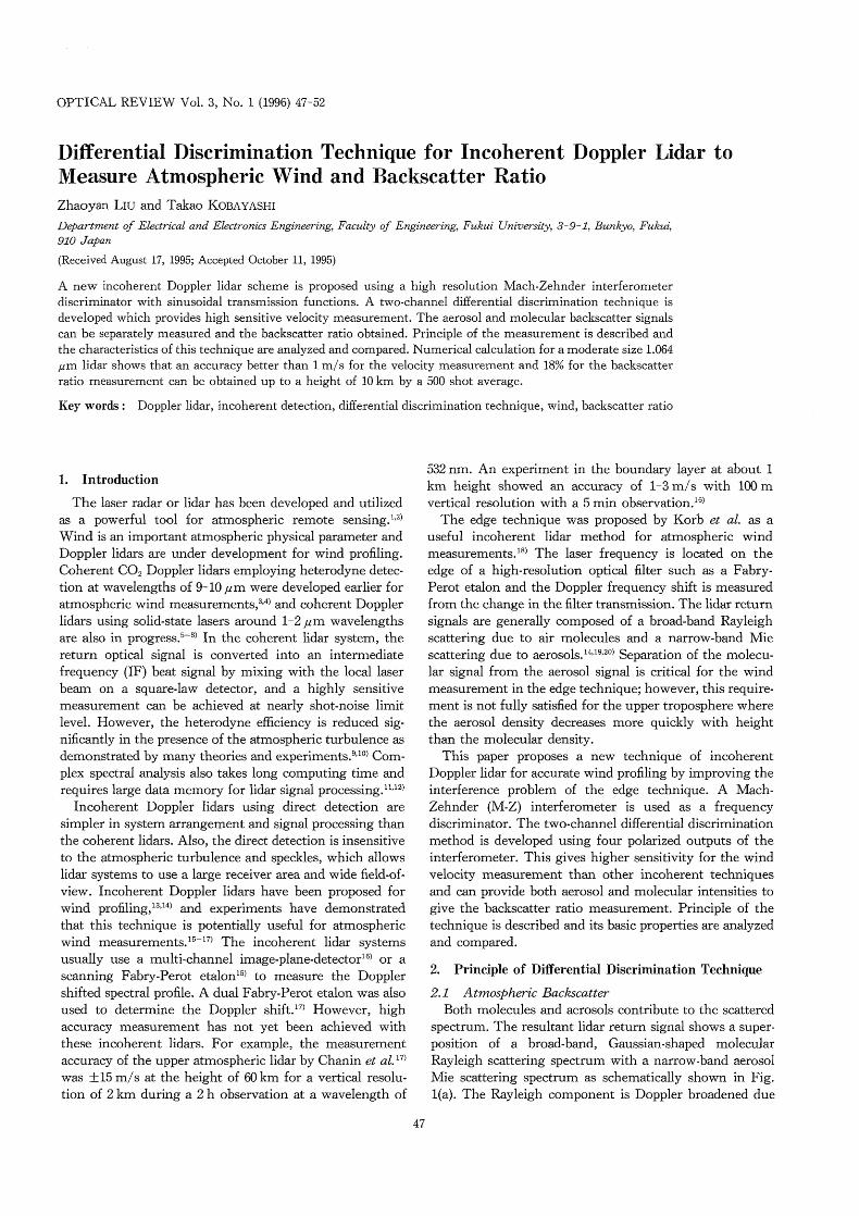
2.1 Atmospheric Backscatter Both molecules and aerosols contribute to the scattered
spectrum. The resultant lidar return signal shows a super-
position of a broad-band, Gaussian-shaped molecular Rayleigh scattering spectrum with a narrow-band aerosol Mie scattering spectrum as schematically shown in Fig. 1(a). The Rayleigh component is Doppler broadened due
47
48 OPTICAL REVIEW Vol. 3, No. I (1996)
>1 ~' (,~
C{ ~) ~J ~t
I~
'-l C~l
~'
~ p~ Cl)
(a)
Aerosol scattering
Laser
Molecular scattering
VL V
~ O
.H c')
(1)
'll
~ c')
C:{
c~}
~
(b) A1:s
\!o
A~ p
Frequency Fig. 1. Schematic of the spectral profiles for the lidar return signal
and the laser beam (a), and the differential transmissions A?;~ and A7lp
of the two-channel Mach-Zehnder interferometer (b). 1'b is the center
frequency of s-polarization channel; VL the laser frequency; v the center frequency of the return signal; (v~ vL) gives the Doppler shift.
to fast thermal motion of the air molecules, and the spectral bandwidth is determined by the atmospheric tem-perature and the laser wavelength. The spectral full width
at half height (FWHH) is, for example, 1.2 GHZ for I pm and 2.4 GHZ for 532 nm at 5 krn altitude with the tempera-ture of 255 K. The Mie scattering spectrum is broadened by random motion of the aerosols and is dependent on the atrnospheric conditions. However, the spectral width is narrow and therefore almost equal to the spectral width of the transmitted laser bearn in the case 0L Q-switch pulsed laser. The two backscattered spectra are Doppler shifted from the laser frequency due to the translation motion of the atrnosphere, i.e. wind velocity.
The backscatter coefficients of the atmospheric aerosols
and molecules depend on the laser wavelength. The molecular backscatter coefficient has ~ -4 dependence and the aerosol backscatter coefficient has ~-1-~ -2 dependence,
so that the signal ratio is dependent on the height, the laser
wavelength and the atmospheric conditions. 2.2 Mach-Zehnder Intelfierometer
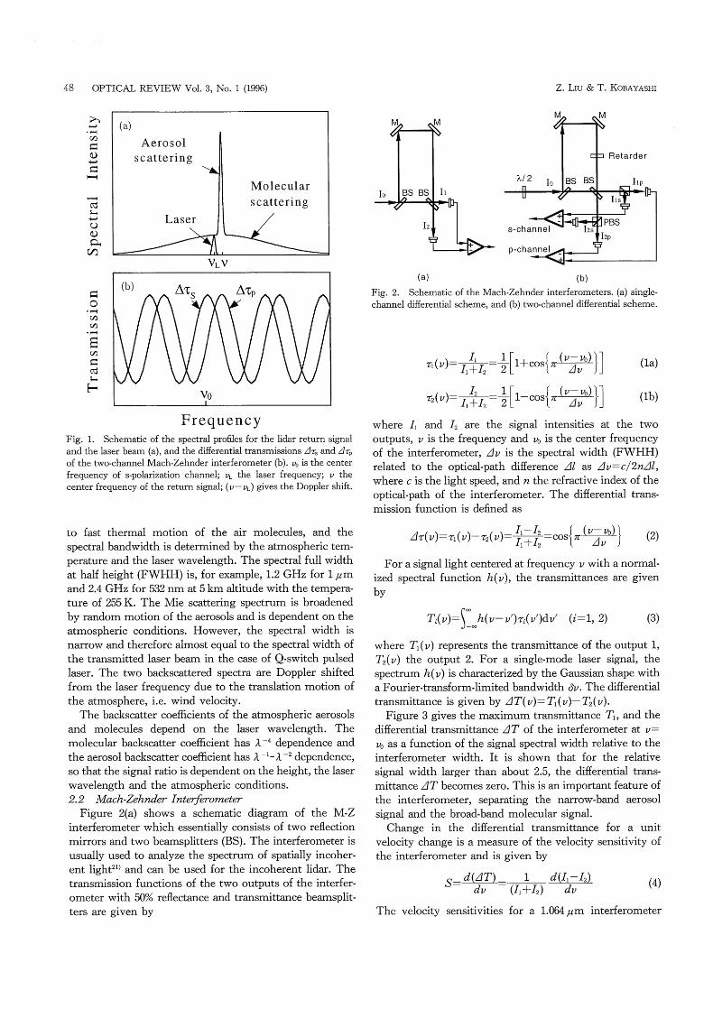
Figure 2(a) shows a schematic diagram of the M-Z interferometer which essentially consists of two reflection
mirrors and two beamsplitters (BS). The interferometer is usually used to analyze the spectrum of spatially incoher-ent light21) and can be used for the incoherent lidar. The transmission functions of the two outputs of the interfer-orneter with 50% reflectance and transmittance beamsplit-
ters are given by
Z. LIU & T. KOBAYASHI
Io
M M
BS BS
12
Il
M M
(a) (b)
Fig. 2. Schematic of the Mach-Zehnder interferometers. (a) single-channel differential scheme, and (b) two-channel differential scheme.
7(v) Il+12=~~ 1+cOSl;Z Av JJ I I ~l~~~l f
1~(v) Il+12=T Av JJ f I I ~~~l 1-cosl 7z:
(1a)
(1b)
where ll and 12 are the signal intensities at the two outputs, v is the frequency and vo is the center frequency
of the interferometer, Av is the spectral width (FWHH) related to the optical-path difference Al as Av=c/2n~ll, where c is the light speed, and n the refractive index of the
optical-path of the interferometer. The differential trans-
mission function is defined as
I1 ~12 _cosf 7rl ~l~J (2) Afl(v)=11(v)-712(v)= Il+12 ~ Av
For a signal light centered at frequency v with a normal-
ized spectral function h(v), the transmittances are given
by
iL Ti(v)= h(v-v')7;i(v')dv' (i=1, 2) (3)
where Tl(v) represents the transmittance of the output 1, T2(v) the output 2. For a single-mode laser signal, the spectrum h(v) is characterized by the Gaussian shape with a Fourier-transform-1irnited bandwidth 6v. The differential
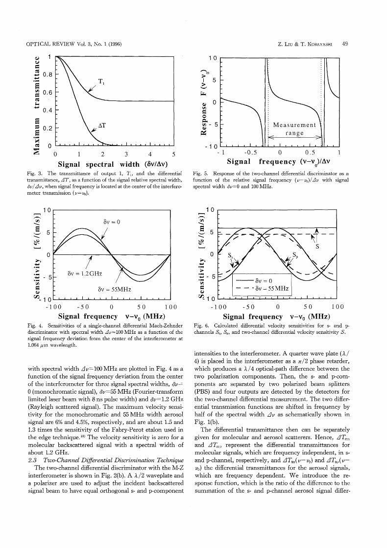
transmittance is given by AT(v)= T1(v)- T2(v). Figure 3 gives the maximum transmittance T1' and the
differential transmittance AT of the interferometer at v= vo as a function of the signal spectral width relative to the
interferometer width. It is shown that for the relative signal width larger than about 2.5, the differential trans-
mittance AT becomes zero. This is an important feature of the interferometer, separating the narrow-band aerosol signal and the broad-band molecular signal.
Change in the differential transmittance for a unit velocity change is a measure of the velocity sensitivity of
the interferometer and is given by
S-~(411_ I ~ldl (4) ~ dv ~ (Il+12) dv The velocity sensitivities for a 1.064 ,clm interferometer
OPTICAL REVIEW Vol. 3, No. I (1996) Z. LIU & T. KOBAYASHI 49
(~) 1 cL)
S::
~ 0.8 ~)
~ cfD 0.6 $::
c:l
~l ~) 0.4
~ :S 0.2 AT 14 ~
.* >~
c:1 O ~:
O 1 2 3 4 5
Signal Spectral Width (5V/AV) Fig. 3. The transmittance of output 1, T*, and the differential transmittance, ZIT, as a function of the signal relative spectral width,
~v/Av, when signal frequency is located at the center 0L the interfero-
meter transmission ( v = vo)'
10
f'o > l 5 ?) \l ~~
(L) O c'~
SI
o ~d c')-5 (L)
e~
-10 0.5 O
Signal frequency (V-Vo)/Av Fig. 5. Response of the two-channel differential discriminator as a function of the relative signal frequency ( v - vo)lllv with signal spectral width (~v=0 and 100 MHz.
10 rl f~ ~)
\ ~ 5 ~J \ ~~:~
L-i
O
h ~•, •r( > ., 5 ~)-..1 c,~
s: (:)
(,~ -10
~v = o
/
/ ~v = 1'2GHZ
~v = 55MHz
-100 -50 O 50 100 Signal frequency V-Vo (MHZ)
Fig. 4. Sensitivities of a single-channel differential Mach-Zehnder discriminator with spectral width 1lv=100 MHZ as a function of the signal frequency deviation from the center of the interferometer at 1 .064 p m wavelength.
10 -~ ~~
~5 ~ \ ~~:'~
- O
~ ~) .* > :~ - 5 ~d
('~Fi
Q)
C'~10
/~'~ / 7 ~:~
S,
~
/
~' \
S /~:
\
~:~
p
\
~~ S
6v = O
- - 6v = 55MHz
~\
/ '\
with spectral width lav=100 MHZ are plotted in Fig. 4 as a function of the signal frequency deviation from the center of the interferometer for three signal spectral widths, (~v=
O (monochromatic signal), (~:v=55 MHZ (Fourier-transform limited laser beam with 8 ns pulse width) and (~:v=1.2 GHZ
(Rayleigh scattered signal). The maximum velocity sensi-tivity for the monochromatic and 55 MHZ Width aerosol signal are 6"/. and 4.5%, respectively, and are about 1.5 and
1.3 times the sensitivity of the Fabry-Perot etalon used in the edge technique.18) The velocity sensitivity is zero for a
molecular backscattered signal with a spectral width of about 1.2 GHz. 2. 8 Two-Channel Dtfferential Discrimination Technique
The two-channel differential discriminator with the M-Z interferometer is shown in Fig. 2(b). A A /2 waveplate and
a polarizer are used to adjust the incident backscattered signal beam to have equal orthogonal s- and p-component
5 O I OO -50 O - I OO
Signal frequency V-Vo (MHZ) Fig. 6. Calculated differential velocity sensitivities for s- and p-channels S~, Sp, and two-channel differential velocity sensitivity S.
intensities to the interferometer. A quarter wave plate ( A /
4) is placed in the interferometer as a 7r/2 phase retarder,
which produces a ~ /4 optical-path difference between the
two polarization components. Then, the s- and p-com-ponents are separated by two polarized beam splitters (PBS) and four outputs are detected by the detectors for the two-channel differential measurement. The two differ-ential transmission Lunctions are shifted in frequency by half of the spectral width Av as schematically shown in Fig. 1(b).
The differential transmittance then can be separately given for molecular and aerosol scatterers. Hence, ATms and ATmp represent the differential transmittances for molecular signals, which are frequency independent, in s-and p-channel, respectively, and ~ITas(v- vo) and ATap(v-vo) the differential transmittances for the aerosol signals,
which are frequency dependent. We introduce the re-sponse function, which is the ratio of the difference to the
summation of the s- and p-channel aerosol signal differ-
50 OPTICAL REVIEW Vol. 3, No I (1996)
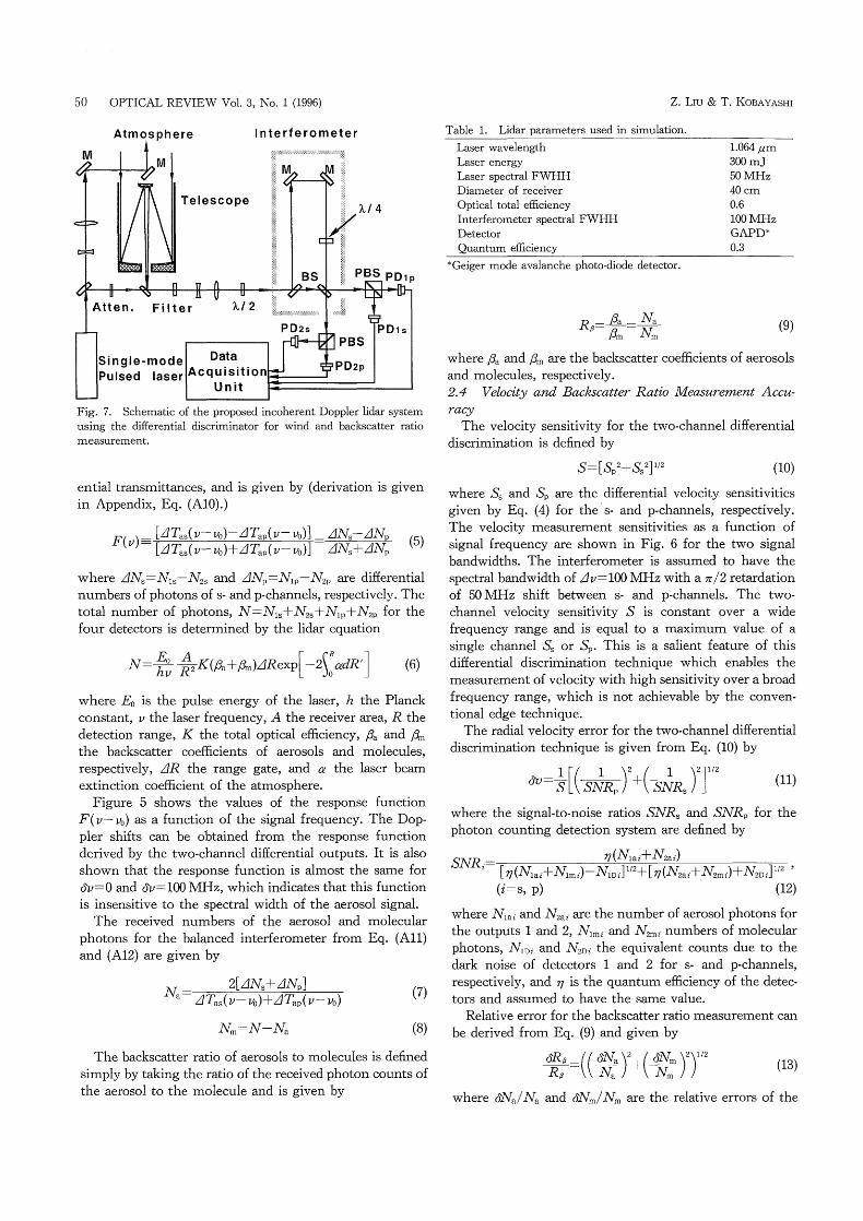
Atmosphere Interferometer
Fig. 7. Schematic of the proposed incoherent Doppler lidar system using the differential discriminator for wind and backscatter ratio
measurement.
ential transmittances, and is given by (derivation is given
in Appendix, Eq. (AIO).)
_ [ZITas(v- vo)~~1Tap(v- vo)] _ 11NS~AN (5) F( v) -
~ [ATas(v- vo)+ATap(v- vo)] ~ IdNS+ANp
where laNs=Nls~N2s and ANp=Nlp~N2p are differential numbers of photons of s- and p'channels, respectively. The
total number of photons, N=Nls+N2s+Nlp+N2p for the four detectors is determined by the lidar equation
N= E~ A K(~ +fi~)ARexp[-2C~ocdR'J hv R'
(6)
where Eo is the pulse energy of the laser, h the Planck constant, v the laser frequency, A the receiver area, R the
detection range. K the total optical efEciency, ~* and fi~
the backscatter coef~cients of aerosols and molecules, respectively, AR the range gate, and c! the laser beam extinction coefficient of the atmosphere.
Figure 5 shows the values of the response function F(v-vo) as a function of the signal frequency. The Dop-pler shifts can be obtained from the response function derived by the two-channel differential outputs. It is also
shown that the response function is almost the same for (~v=0 and (~v=100 MHz, which indicates that this function is insensitive to the spectral width of the aerosol signal.
The received numbers of the aerosol and molecular photons for the balanced interferometer from Eq. (A11) and (A12) are given by
2[ZINs+ANp] Na~ ATas( v- vo)+ATap( v- vo)
Nm:=N-Na
(7)
(8)
The backscatter ratio of aerosols to molecules is defined
simply by taking the ratio of the received photon counts of
the aerosol to the molecule and is given by
Z. LIU & T. KOBAYASHI
Table 1. Lidar parameters used in simulation.
Laser wavelength Laser energy Laser spectral FWHH Diameter of receiver Optical total efficiency
Interferometer spectral FWHH Detector Quantum efiiciency
1.064 pm 300 mJ 50 MHZ 40 cm 0.6
lOO MHZ GAPD* 0.3
* Geiger mode avalanche photo-diode detector.
R =A= Na (9) fi~n N* where fia and ~n are the backscatter coefiicients of aerosols
and molecules, respectively.
2.4 Velotity and Backscatter Ratio Measurement Accu-
racy The velocity sensitivity for the two-channel differential
discrimination is defined by
S=[Sp2+Ss2]l/2 (10) where Ss and Sp are the differential velocity sensitivities
given by Eq. (4) for the s- and p-channels, respectively. The velocity measurement sensitivities as a function of signal frequency are shown in Fig. 6 for the two signal bandwidths. The interferometer is assumed to have the spectral bandwidth of Av=100 MHZ With a 'r/2 retardation of 50 MHZ shift between s- and p-channels. The two-channel velocity sensitivity S is constant over a wide frequency range and is equal to a maximum value of a single channel Ss or Sp. This is a salient feature of this
differential discrimination technique which enables the measurement of velocity with high sensitivity over a broad
frequency range, which is not achievable by the conven-tional edge technique.
The radial velocity error for the two-channel differential
discrimination technique is given from Eq. (10) by
2 )2J1/2 (~v ~[(SNIRp + SNR (11) ( 1
where the signal-to-noise ratios SNRS and SNRp for the photon counting detection system are defined by
SNRi- 77(Nlai+N2ai) ~ [17(Nlai+Nlmi)+NIDi]l/2+[77(N2ai+N2mi)+N2Di]l/2 '
(i=s, p) (12) where Nlai and N2ai are the number of aerosol photons for the outputs I and 2, Nlmi and N2mi numbers of molecular photons, NIDi and N2Di the equivalent counts due to the dark noise of detectors I and 2 for s- and p-channels, respectively, and ?7 is the quantum efficiency of the detec-
tors and assumed to have the sarne value. Relative error for the backscatter ratio measurement can
be derived from Eq. (9) and given by
(( 2 6N~ )2)1/2 p ) (~:R (~:Na + Nm where (~:*Na/Na and (~;N~/Nm are the relative errors of the
OPTICAL REVIEW Vol. 3, No. I (1996)
2 '~, ~~ ~
~'1 .5
~ o ~ ~ 1 (L)
h :::c•~0.5 o -~)
> O
~ = I .064 um
Zenith angle: e =40' Shot average: N = 500
6R IR ~ ~
6N IN **' n'
~1) 6N*/N*
\
0.5
0.4
0.3
~ o ~ ~ <L)
~,
> 0.2 •-~) c:l
~ cL)
0.1 e~
o
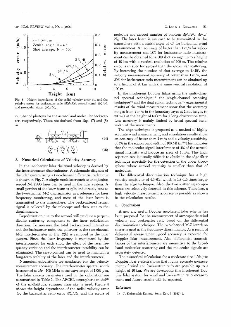
O 2 4 6 8 10 Height (km) Fig. 8. Height dependence of the radial velocity error (~v, and the relative errors for backscatter ratio (5:R~/Rfi , aerosol signal (5Na/Na
and molecular signal (~:N*/Nm '
number 0L photons for the aerosol and molecular backscat-ter, respectively. These are derived from Eqs. (7) and (8)
as
(~:N. ' )'J"' [( . ( ) , + SNR SNR Na [AfTas( v- vo)+~Tap( v- vo)]
N~ ~("~NN_~)(~) ~N~_
3. Numencal Calculatrons of Velocity Accuracy
(14)
(15)
In the incoherent lidar the wind velocity is derived by the interferometer discriminator. A schematic diagram of the lidar system using a two-channel differential technique is shown in Fig. 7. A single-mode laser such as an injection
seeded Nd:YAG Iaser can be used in the lidar system. A small portion of the laser beam is split and directly sent to
the two-channel M-Z discriminator as a reference for laser
frequency monitoring, and most of the laser beam is transmitted to the atmosphere. The backscattered return signal is collected by the telescope and then sent to the discrirninator.
Depolarization due to the aerosol will produce a perpen-
dicular scattering component to the laser polarization direction. To measure the total backscattered intensities and the backscatter ratio, the polarizer in the two-channel
M-Z interferometer in Fig. 2(b) is removed in the lidar system. Since the laser frequency is monitored by the interferometer for each shot, the effect of the laser fre-quency variation and the interferometer instability can be
eliminated. The servo-control can be used to maintain a long-term stability of the laser and the interferometer.
Numerical calculations are conducted for the velocity measurement accuracy. The interferometer spectral width is assumed as Av=100 MHZ at the wavelength of 1.064 ,am. The lidar system parameters used in the calculation are summarized in Table 1. The AFCRL atmospheric model22) of the midlatitude, summer clear sky is used. Figure 8 shows the height dependence of the radial velocity error (~v, the backscatter ratio error (~;RfilRp, and the errors 0L
Z. LIU & T. KOBAYASHI 51
molecule and aerosol number of photons (~:rNa/Na' (~:N^/ Nm' The laser beam is assumed to be transmitted in the atmosphere with a zenith angle of 40' for horizontal wind measurement. An accuracy of better than I m/s for veloc-ity measurement and 18% for backscatter ratio measure-ment can be obtained for a 500 shot average up to a height of 10 km with a vertical resolution of 100 m. The relative error is smaller for aerosol than the molecular scattering.
By increasing the number of shot average to 4xl04, the velocity measurement accuracy 0L better than I m/s, and 20% for backscatter ratio measurement can be obtained up to a height of 20 km with the sarne vertical resolution of
IOO m. In the incoherent Doppler lidars using the multi-chan-
nel spectral technique,16) the single-channel scanning techniquel5) and the dual-etalon technique,17) experimental
results of the wind measurement show that the accuracy ranges from 2 m/s in the boundary layer at I km height to 30 m/s at the height of 60 km for a long observation time.
Low accuracy is mainly limited by broad spectral band-width of the instruments.
The edge technique is proposed as a method of highly accurate wind measurement, and simulation results show an accuracy of better than I m/s and a velocity sensitivity of 40/0 in the etalon bandwidth of 100 MHz.18) This indicates
that the molecular signal interference of 4% of the aerosol
signal intensity will induce an error of I m/s. This high rejection rate is usually dif~cult to obtain in the edge filter
technique especially for the detection of the upper tropo-
sphere where aerosol intensity is smaller than that of molecules.
The differential discrimination technique has a high velocity sensitivity of 4.5-6%, which is 1.3-1.5 times larger
than the edge technique. Also, the two scattering compo-nents are selectively detected in this scheme. Therefore, a
high velocity measurement accuracy is possible as shown in the calculation results.
4. Conclusions
A new and useful Doppler incoherent lidar scheme has been proposed for the measurement of atmospheric wind velocity and backscatter ratio based on the differential discrimination technique. The two-channel M-Z interfero-meter is used as the frequency discriminator. As a result of
differential measurement, good accuracy is expected for Doppler lidar measurement. Also, differential transmit-tances of the interferometer are insensitive to the broad-band molecular scattering and the molecular signals are separately detected.
The numerical calculation for a moderate size 1.064 pm Doppler lidar system shows that highly accurate measure-ment of wind and backscatter ratio are possible up to a height of 10 km. We are developing this incoherent Dop-pler lidar system for wind and backscatter ratio measure-ment and future results will be reported.
Ref erences
1) T. Kobayashi: Remote Sens. Rev. 3 (1987) 1.
52 OPTICAL REVIEW Vol. 3, No. I (1996)
2) H. Inaba, T. Kobayashi and N. Takeuchi, ed: Rev. Laser Eng. 23 (Special issue on laser radar) (1994) 87.
3) J. Bilbro, G. Fichtl, D. Fitzjarrald, M. Krause and R. Lee: Bull.
Am. Meterol. Soc. 65 (1984) 348. 4) F.F. Hall, Jr.. R.M. Huffaker, R.M. Hardesty. M. Jackson, T.R.
Lawrence, M. Post, R. Ritcher and B.F. Weber: Appl. Opt. 23 (1983) 2503.
5) T.J. Kane, W. Kozlovsky, R. Byer and C. Byvik: Opt. Lett. 12 (1987) 239.
6) M. Kavaya, S. Henderson, J. Magee, C. Hale and R.M. Huffaker: Opt. Lett. 14 (1989) 776.
7) S.W. Henderson, C.P. Hale, J.R. Magee,M.J. Kavaya and A.M. Huffaker: Opt. Lett. 16 (1991) 773.
8) Z. Liu, M. Kawai, T. Taira and T. Kobayashi: Proc. 17th International Laser Radar Conference, Sendai, Japan, 1994, 28PD2 (1994) p. 482.
9) K.P. Chan, D.K. Killinger and N. Sugimoto: Appl. Opt. 30 (1991) 2617.
10) R.G. Frelich and M.J. Kavaya: Appl. Opt. 30 (1991) 5325.
11) B.J. Rye and R.M. Hardesty: IEEE Trans. Geosci. Remote Sens. GE-31 (1993) 16.
12) S.L. Marple, Jr.: Dl~ital Spectral Analysis with Applications (Prentice-Hall, Inc., 1987).
13) V. Abreu: Appl. Opt. 18 (1979) 2992. 14) D. Rees and I.S. McDermid: Appl. Opt. 29 (1990) 4133. 15) C.A. Tepley, S.1. Sargoyichev and R. Rojas: IEEE Trans.
Geosci. Remote Sens. 31 (1993) 36. 16) K.W. Fischer, V.J. Abreu, W.R. Skinner, J.E. Barnes, M.J.
McGill and T.D. Irgang: Opt. Eng. 34 (1995) 499. 17) M.L. Chanin, A. Garnier, A. Hauchecorne and J. Porteneuve:
Geophys. Res. Lett. 16 (1989) 1273.
18) C.L. Korb, B.M. Gentry and C.Y. Weng: Appl. Opt. 31 (1992) 4203.
19) G. Fiocco and J.B. DeWolf: J. Atmos. Sci. 25 (1968) 488. 20) G. Benedetti-Michelangeli, F. Congeduti and G. Fiocco: J.
Atmos. Sci. 29 (1972) 906.
21) M. Born and E. Wolf: Principles of Q~)tics (Oxford, U.K., Pergamon Press Ltd., 1965) Chap. VII, p. 312.
22) R.A. McClatchey, R. Fenn, J. Selby, F. Volz and J. Garing: (U.S. Air Force Cambridge Research Laboratory, Bedford, Mass.. Environmental Research Paper 72-0497, 1972).
Appendix: Derivation of Response Function and Aerosol and Molecular Signals
The number of photons received in the four outputs of the two-channel differential M-Z interferometer shown in Fig. 2(b) are
( ) Nls~7'LT T J~7\T rT' V- VO lvms I Ims ~JLYas I Ias
L7\T rr N2s Nas T2as ( V Vo ) ~ TIYms 1 2ms ) Nlp:IN T (V-Vo TNmpTlmp L ap lap
N2p:~NapT ( - )L rrf 2ap V Vo TNmp J: 2mp
(A1)
(A2)
(A3)
(A4)
where Nas' Nap' N~s and Nmp are the numbers of photons of aerosol and molecular backscattered signals in s- and p-polarization channels, respectively, Tlas' Tlap' T2as and
T2ap are transmittances of the interferometer in output 1 and output 2 for s- and p-channel aerosol signals, Tlms'
Z. LlU & T. KOBAYASHI
T Tlmp and T2mp are the molecular transnuttances of 2ms' output I and output 2 for s- and p-channels. Difference in
number of photons of s- and p-components in output I and output 2 can be obtained from the four equations, Eq. (A1)-(A4) and given by
~lNs=Nls~N2s=NasATas( v- vo)+NmsATms (A5)
AN Nlp N2p NapAfTap(v-vo)+NmpATmp (A6) where ATas(v-vo)' ATap(v-vo)' ATms and ATmp are the differential transmittances of the aerosol and the molecular
signals for s- and p-components, and the notations ATas
(v-vo)=Tlas~T2as' ATap(v-vo)=Tlap~T2ap' ATms=Tlms~ T2ms and ATmp=Tlmp~T2mp are used. Using a ~/2 wave-plate and a polarizer we can adjust the incident light to be
Nas=Nap and Nms=Nmp for s- and p-components. The difference and the summation of 11NS and ANp are
N AN ANp- 2 (ATms+~lTmp) Nas[ATas( v- vo)~ATap( v- vo)~ (ATms+ Z1 Tmp)]
(A7)
N AN +ANp- 2 (IdTms+ATmp)
=Nas[ATas(v-vo)+ATap(v-vo)~(ATms+ATmp)] (A8)
The response function F(v- vo)' which is the ratio of the difference to the summation of the s- and p-polarized differential transmittances taking into account the effect of
the molecular backscattered signal, can be readily obtained
from Eqs. (A7) and (A8) as given by
[ATas( v- vo)~ATap( v- vo)] ~ (~1 Tms~ATmp) F(v vo)= [ATas(v-vo)+1dTap(v-vo)]~(ATms+ATmp)
(ANs~laNp)-(ATns~AT~p)N/2 (ANs+ANp)-(ATms+ATmp)N/2
In the balanced interferometer, we can assume AT~s= ATmp=0, then the response function is simplified as by
[ATas( v- vo)~ATap(v- vo)] (AN -ANp)
F( v- vo)= = S [ATas( v- vo)+ATap( v- vo)] (ANS+ANp) (AIO)
The number of photons for aerosol and molecular back-scattered signal is given by
2[(ANs+ANp)-(ATms+AT^p)N/2] Na~
(A9)
where
ATas( v- vo)+~1 Tap( v- vo)~ (ATms+ATmp)
Nm=N-Na
(A11)
(A12)
N=N1*+N2*+Nlp+N2p=N*+Np (A13) is the total number of photons of the four detectors.