die casting aluminum and zinc for injection … casting aluminum and zinc for injection molders ......
TRANSCRIPT
DIE CASTING ALUMINUM AND ZINC for INJECTION MOLDERS
By Howard MullinControl Plastics Inc.
www.ControlPlastics.com
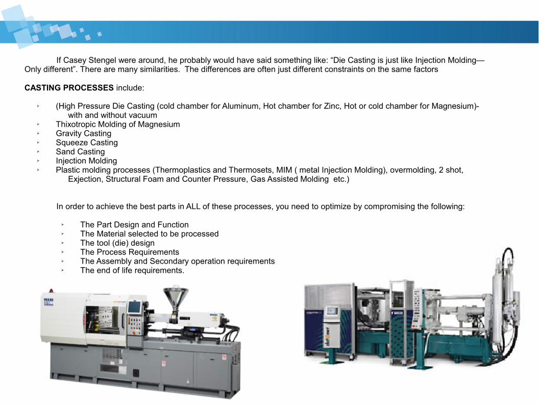
If Casey Stengel were around, he probably would have said something like: “Die Casting is just like Injection Molding—Only different”. There are many similarities. The differences are often just different constraints on the same factors CASTING PROCESSES include:
➢ (High Pressure Die Casting (cold chamber for Aluminum, Hot chamber for Zinc, Hot or cold chamber for Magnesium)- with and without vacuum
➢ Thixotropic Molding of Magnesium ➢ Gravity Casting➢ Squeeze Casting➢ Sand Casting➢ Injection Molding➢ Plastic molding processes (Thermoplastics and Thermosets, MIM ( metal Injection Molding), overmolding, 2 shot,
Exjection, Structural Foam and Counter Pressure, Gas Assisted Molding etc.)
In order to achieve the best parts in ALL of these processes, you need to optimize by compromising the following:
➢ The Part Design and Function➢ The Material selected to be processed➢ The tool (die) design➢ The Process Requirements➢ The Assembly and Secondary operation requirements➢ The end of life requirements.
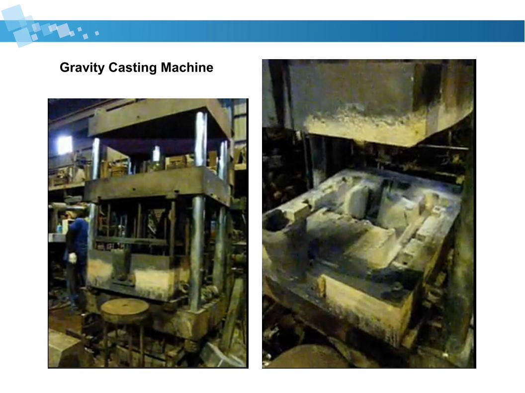
Gravity Casting Machine
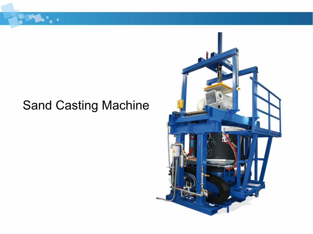
Sand Casting Machine
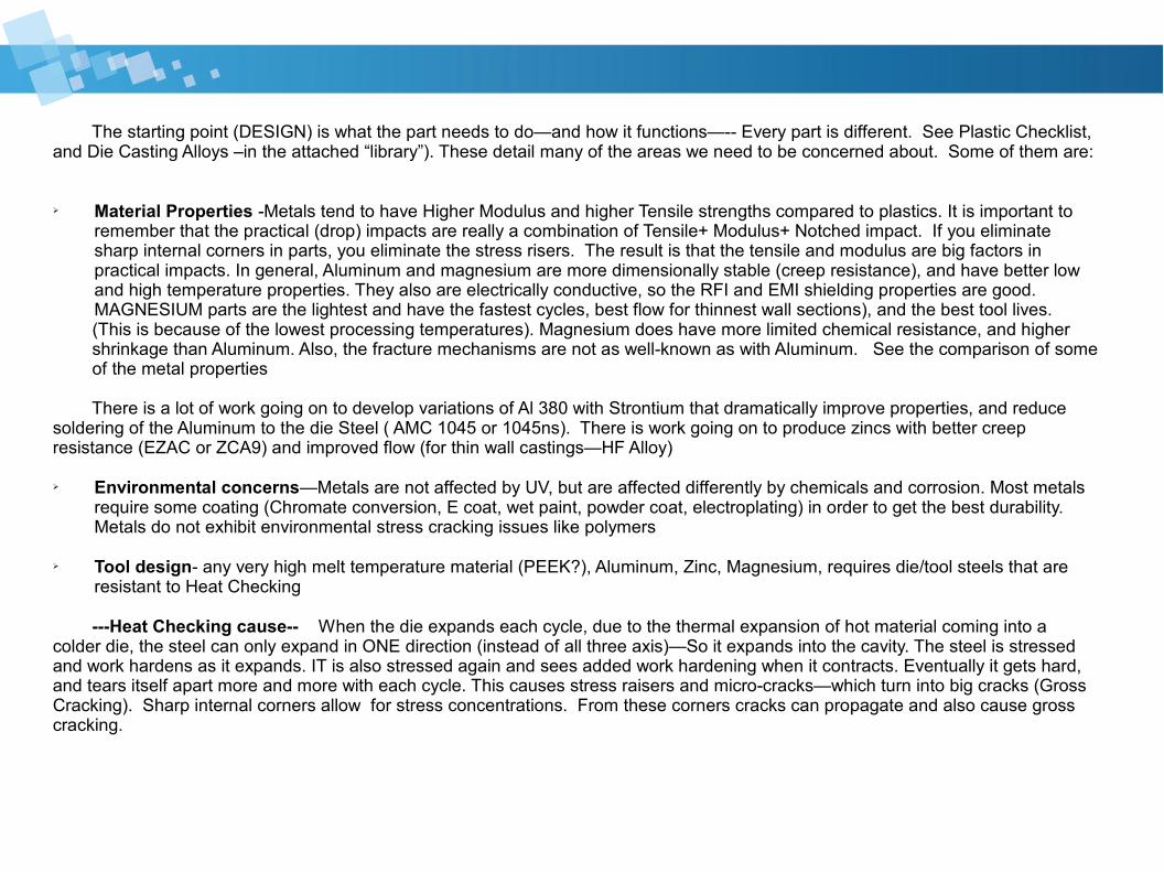
The starting point (DESIGN) is what the part needs to do—and how it functions—-- Every part is different. See Plastic Checklist, and Die Casting Alloys –in the attached “library”). These detail many of the areas we need to be concerned about. Some of them are: ➢ Material Properties -Metals tend to have Higher Modulus and higher Tensile strengths compared to plastics. It is important to
remember that the practical (drop) impacts are really a combination of Tensile+ Modulus+ Notched impact. If you eliminate sharp internal corners in parts, you eliminate the stress risers. The result is that the tensile and modulus are big factors in practical impacts. In general, Aluminum and magnesium are more dimensionally stable (creep resistance), and have better low and high temperature properties. They also are electrically conductive, so the RFI and EMI shielding properties are good. MAGNESIUM parts are the lightest and have the fastest cycles, best flow for thinnest wall sections), and the best tool lives.
(This is because of the lowest processing temperatures). Magnesium does have more limited chemical resistance, and higher shrinkage than Aluminum. Also, the fracture mechanisms are not as well-known as with Aluminum. See the comparison of some of the metal properties
There is a lot of work going on to develop variations of Al 380 with Strontium that dramatically improve properties, and reduce soldering of the Aluminum to the die Steel ( AMC 1045 or 1045ns). There is work going on to produce zincs with better creep resistance (EZAC or ZCA9) and improved flow (for thin wall castings—HF Alloy)
➢ Environmental concerns—Metals are not affected by UV, but are affected differently by chemicals and corrosion. Most metals require some coating (Chromate conversion, E coat, wet paint, powder coat, electroplating) in order to get the best durability. Metals do not exhibit environmental stress cracking issues like polymers
➢ Tool design- any very high melt temperature material (PEEK?), Aluminum, Zinc, Magnesium, requires die/tool steels that are resistant to Heat Checking
---Heat Checking cause-- When the die expands each cycle, due to the thermal expansion of hot material coming into a colder die, the steel can only expand in ONE direction (instead of all three axis)—So it expands into the cavity. The steel is stressed and work hardens as it expands. IT is also stressed again and sees added work hardening when it contracts. Eventually it gets hard, and tears itself apart more and more with each cycle. This causes stress raisers and micro-cracks—which turn into big cracks (Gross Cracking). Sharp internal corners allow for stress concentrations. From these corners cracks can propagate and also cause gross cracking.
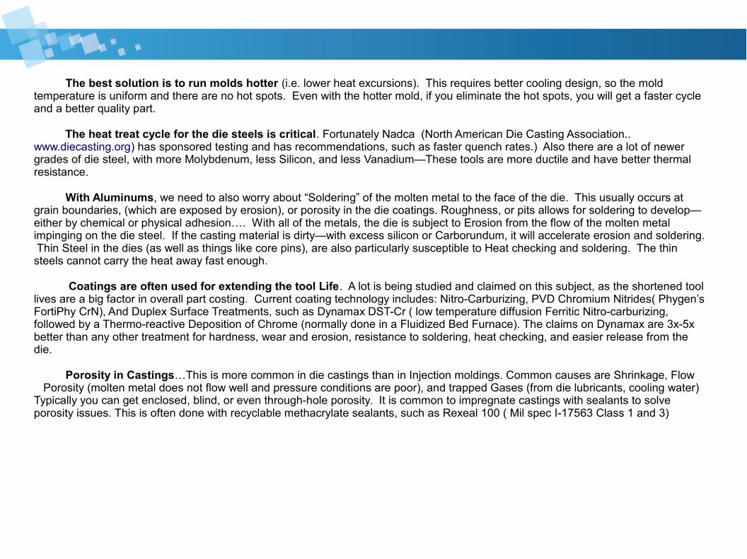
The best solution is to run molds hotter (i.e. lower heat excursions). This requires better cooling design, so the mold temperature is uniform and there are no hot spots. Even with the hotter mold, if you eliminate the hot spots, you will get a faster cycle and a better quality part.
The heat treat cycle for the die steels is critical. Fortunately Nadca (North American Die Casting Association.. www.diecasting.org) has sponsored testing and has recommendations, such as faster quench rates.) Also there are a lot of newer grades of die steel, with more Molybdenum, less Silicon, and less Vanadium—These tools are more ductile and have better thermal resistance. With Aluminums, we need to also worry about “Soldering” of the molten metal to the face of the die. This usually occurs at grain boundaries, (which are exposed by erosion), or porosity in the die coatings. Roughness, or pits allows for soldering to develop—either by chemical or physical adhesion…. With all of the metals, the die is subject to Erosion from the flow of the molten metal impinging on the die steel. If the casting material is dirty—with excess silicon or Carborundum, it will accelerate erosion and soldering. Thin Steel in the dies (as well as things like core pins), are also particularly susceptible to Heat checking and soldering. The thin steels cannot carry the heat away fast enough.
Coatings are often used for extending the tool Life. A lot is being studied and claimed on this subject, as the shortened tool lives are a big factor in overall part costing. Current coating technology includes: Nitro-Carburizing, PVD Chromium Nitrides( Phygen’s FortiPhy CrN), And Duplex Surface Treatments, such as Dynamax DST-Cr ( low temperature diffusion Ferritic Nitro-carburizing, followed by a Thermo-reactive Deposition of Chrome (normally done in a Fluidized Bed Furnace). The claims on Dynamax are 3x-5x better than any other treatment for hardness, wear and erosion, resistance to soldering, heat checking, and easier release from the die.
Porosity in Castings…This is more common in die castings than in Injection moldings. Common causes are Shrinkage, Flow Porosity (molten metal does not flow well and pressure conditions are poor), and trapped Gases (from die lubricants, cooling water) Typically you can get enclosed, blind, or even through-hole porosity. It is common to impregnate castings with sealants to solve porosity issues. This is often done with recyclable methacrylate sealants, such as Rexeal 100 ( Mil spec I-17563 Class 1 and 3)
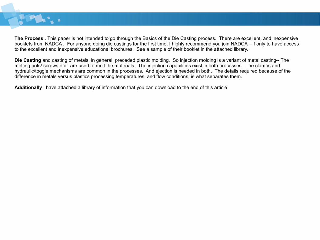
The Process.. This paper is not intended to go through the Basics of the Die Casting process. There are excellent, and inexpensive booklets from NADCA . For anyone doing die castings for the first time, I highly recommend you join NADCA—if only to have access to the excellent and inexpensive educational brochures. See a sample of their booklet in the attached library.
Die Casting and casting of metals, in general, preceded plastic molding. So injection molding is a variant of metal casting-- The melting pots/ screws etc. are used to melt the materials. The injection capabilities exist in both processes. The clamps and hydraulic/toggle mechanisms are common in the processes. And ejection is needed in both. The details required because of the difference in metals versus plastics processing temperatures, and flow conditions, is what separates them.
Additionally I have attached a library of information that you can download to the end of this article
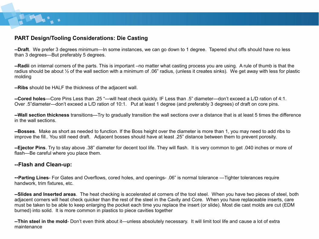
PART Design/Tooling Considerations: Die Casting
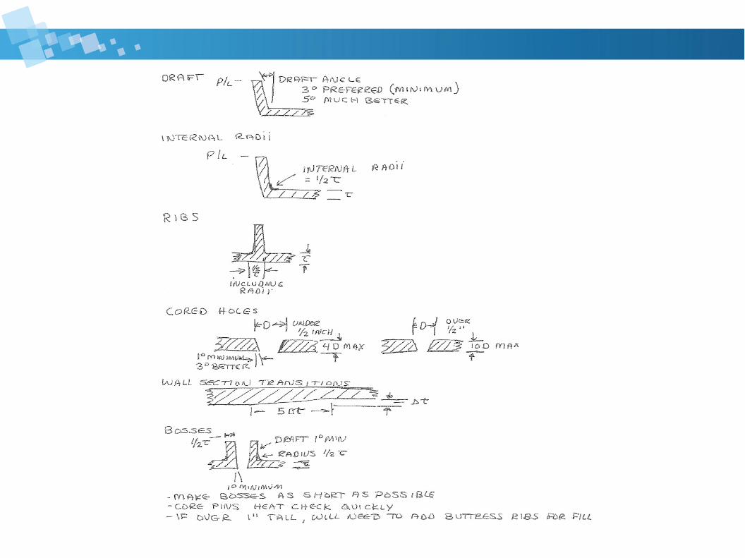
--Draft. We prefer 3 degrees minimum—In some instances, we can go down to 1 degree. Tapered shut offs should have no less than 3 degrees—But preferably 5 degrees.
--Radii on internal corners of the parts. This is important –no matter what casting process you are using. A rule of thumb is that the radius should be about ½ of the wall section with a minimum of .06” radius, (unless it creates sinks). We get away with less for plastic molding
--Ribs should be HALF the thickness of the adjacent wall.
--Cored holes—Core Pins Less than .25 “—will heat check quickly. IF Less than .5” diameter—don’t exceed a L/D ration of 4:1. Over .5”diameter—don’t exceed a L/D ration of 10:1. Put at least 1 degree (and preferably 3 degrees) of draft on core pins.
--Wall section thickness transitions—Try to gradually transition the wall sections over a distance that is at least 5 times the difference in the wall sections.
--Bosses. Make as short as needed to function. If the Boss height over the diameter is more than 1, you may need to add ribs to improve the fill.. You still need draft. Adjacent bosses should have at least .25” distance between them to prevent porosity.
--Ejector Pins. Try to stay above .38” diameter for decent tool life. They will flash. It is very common to get .040 inches or more of flash—Be careful where you place them.
--Flash and Clean-up:
--Parting Lines- For Gates and Overflows, cored holes, and openings- .06” is normal tolerance —Tighter tolerances require handwork, trim fixtures, etc.
--Slides and Inserted areas. The heat checking is accelerated at corners of the tool steel. When you have two pieces of steel, both adjacent corners will heat check quicker than the rest of the steel in the Cavity and Core. When you have replaceable inserts, care must be taken to be able to keep enlarging the pocket each time you replace the insert (or slide). Most die cast molds are cut (EDM burned) into solid. It is more common in plastics to piece cavities together
--Thin steel in the mold- Don’t even think about it—unless absolutely necessary. It will limit tool life and cause a lot of extra maintenance
Tool Maintenance. With Aluminum, it is common to do complete tool maintenance every 5000 shots. ( less often with Zinc—and even less with Magnesium). Heat checking and cracking are the main issues.Typical tool lives for hardened H13 molds—aluminum 50K-100K shots, Zinc 500K +/- shots Magnesium- 400K +/-
Maintenance often includes clean up and pre stressing the surfaces by shot blasting or laser peening.
Different steels will get different tool lives. And we have a number of steels that are appreciably better than H-13 (DH-31- for example)]
--MACHINING of Castings. Please remember that all casting processes (metal and plastic) create higher density “skins”.
Machining these surfaces away can affect properties. That being said, it is very normal to do a lot of clean up (trimming gates and overflows, removing flash), as well as intended machining (drill and tap holes, tweaking tight dimensions).
Often the parting line flash, as well as trimming of gates and overflows, is done by a trim die, and then smoothed out by machining or power sanders.
Machined tolerances are tighter than the “as cast” tolerances. NADCA publishes standards. Many customers use NADCA standards as a reference, but keep pushing for tighter tolerances—(More like what we achieve in Injection molding).
--Heat Treating of High Pressure Die Castings. Until recently, HPDC parts were not heat treated. This was because the pores would expand and cause surface Blisters. CSIRO Light Metals Flagship of Australia, (and Mercury Marine—with grants from NADCA), established heat treating methods that will work (See articles in the “library” attached.).
In general the tensile, fatigue resistance, and fracture resistance properties are all improved. Additionally, due to changes in the alloy structures, the appearances of anodizing and electro-polishing have been improved. This has also lead to the development of new alloys that may be even better for heat treating.
-- Special materials—K Alloy. Delphi Electronics was instrumental in developing a special Aluminum alloy, (K alloy), that has dramatically improved chemical resistance. The numbers show that K Alloy will out-perform Al 383 that has been allodyne and coated. Currently this material is only produced at one foundry in the USA. Data included in the “library”.
HIGH VOLUME vs Low volume Typically the high volume casting methods, like die casting, gravity casting, and injection molding, have a lot of advantages:
➢ Better tolerance and dimensional control (more consistent and automated processes)➢ Faster Cycle times (and lower costs)➢ Better finishes and better reproduction of the die finishes➢ Less secondary operations ➢ Thinner wall section capabilities
But they come with a compromise. Higher production tools tend to be more demanding ( higher cost) on the quality of molds/dies that you need. There are master die base systems—similar to in MUD sets in Injection molding. These may help minimize tooling costs. And they do minimize set up times and costs. They are usually more expensive to make changes to (and more cavities may mean lower part cost—but it means more costs every time there is a tool change).
As always, the best product is determined by the best compromise of all the factors: Function, Casting Material, Die Design, Processing constraints, Secondary operations and Assembly, End of Life issues
At Control Plastics---We do plastics. And we do metals--
Our only goal is to get you the best product for your application
Library of information available at this address http://www.controlplastics.com/injection_molding/library2/index.php
Control Plastics Inc. SSF CA 94080 800-600-2010 www.controlplastics.com