development of xml schemas for implementation of … of xml schemas for implementation of a 3d...
TRANSCRIPT
131 Ali Aien, Abbas Rajabifard, Mohsen Kalantari, Ian Williamson and Davood Shojaei Development of XML Schemas for Implementation of a 3D Cadastral Data Model 4th International Workshop on 3D Cadastres 9-11 November 2014, Dubai, United Arab Emirates
Development of XML Schemas for Implementation of a 3D Cadastral Data Model
Ali AIEN, Abbas RAJABIFARD, Mohsen KALANTARI, Ian WILLIAMSON and
Davood SHOJAEI, Australia
Key words: 3D Cadastral Data Modelling, 3DCDM, XML Schema SUMMARY A 3D cadastral data model (3DCDM) was developed to support integration of legal and physical information that are required for 3D cadastral applications. The 3DCDM model has twelve sub-models or modules including 3DCDM Geometry Model, 3DCDM Root Model, 3DCDM LegalPropertyObject Model, 3DCDM InterestHolder Model, 3DCDM Survey Model, 3DCDM CadastralPoints Model, 3DCDM Building Model, 3DCDM Land Model, 3DCDM Tunnel Model, 3DCDM UtilityNetwork Model, 3DCDM PhysicalPropertyObject Model, and 3DCDM Terrain Model. Sub-models are selected based on the user requirements and the application. For example, if the purpose of using the 3DCDM model is to model a building and visualise its ownership boundaries, only 3DCDM Building Model and 3DCDM Root Model are used. The 3DCDM Root Model must be used in each implementation of the 3DCDM model. This paper aims to develop a physical data model of the 3DCDM model. It is developed as an application schema of the Geography Markup Language 3, version GML3.2.1. GML is an XML grammar defined by the Open Geospatial Consortium (OGC) to express geographical features. Each module has a separate schema that support implementation of the 3DCDM model.
132 Ali Aien, Abbas Rajabifard, Mohsen Kalantari, Ian Williamson and Davood Shojaei
Development of XML Schemas for Implementation of a 3D Cadastral Data Model
4th International Workshop on 3D Cadastres 9-11 November 2014, Dubai, United Arab Emirates
Development of XML Schemas for Implementation of a 3D Cadastral Data Model
Ali AIEN, Abbas RAJABIFARD, Mohsen KALANTARI, Ian WILLIAMSON and
Davood SHOJAEI, Australia 1. INTRODUCTION The aim of this paper is to convert the logical data model of the 3D Cadastral Data Model (3DCDM) to a physical data model. The physical data model of the 3DCDM has been developed as an application schema of the Geography Markup Language 3, version GML3.2.1. GML is an XML grammar defined by the Open Geospatial Consortium (OGC) to express geographical features (ISO19136, 2007). Accordingly, the physical data model of the 3DCDM is an XML based schema. The 3DCDM model is decomposed into twelve sub-models (modules). The 3DCDM geometry module is a GML profile. It is a subset of GML (GML3.2.1). GML3.2.1’s schema (http://schemas.opengis.net/gml/3.2.1/gml.xsd) is imported into the 3DCDM. Therefore, eleven schemas, one schema per module, are developed. An advantage of having separate sub-models (modules) and also XML schemas is to increase the efficiency of implementation of the 3DCDM model. Users can choose the appropriate module and avoid utilising unnecessary modules. 2. 3DCDM 3D Cadastral Data Model (3DCDM) was developed as a solution capable of supporting 3D data, integrating 3D physical objects with their corresponding 3D legal objects, and featuring semantically enriched objects. The data model is developed based on the ISO standards and UML modelling language is used to specify the data model. The 3DCDM model represents 3D legal objects and connects legal and physical objects together. In this regard, the 3DCDM model is equipped with the concepts of the Legal Property Object (LPO) and the Physical Property Object (PPO). The first facilitates modelling of all existing interests (RRR) as legal objects. The second considers all 3D urban features such as buildings, tunnels, and utilities as physical objects. 3D geometric primitives of GML (Geographic Markup Language) such as Solid and MultiSurface are used to define the Legal and Physical Property Objects. The 3DCDM model supports semantics that define every aspect of legal and physical objects, and therefore, it facilitates their integration.
The 3DCDM model is composed of two hierarchies: legal and physical. However, they are connected to each other through the associations between their subclasses. The 3DCDM’s users can navigate through each hierarchy independently and also between hierarchies. Each hierarchy consists of different components and they are all connected to the core component of the 3DCDM model, which is called the root model. The root model contains the basic features on the 3DCDM model. The root model must be implemented in any conformant

133 Ali Aien, Abbas Rajabifard, Mohsen Kalantari, Ian Williamson and Davood Shojaei Development of XML Schemas for Implementation of a 3D Cadastral Data Model 4th International Workshop on 3D Cadastres 9-11 November 2014, Dubai, United Arab Emirates
system. The legal hierarchy of the 3DCDM model comprises of the following components: LegalPropertyObject, Survey, CadastralPoint, and InterestHolder. The physical hierarchy has the following components: PhysicalPropertyObject, Building, Land, Tunnel, UtilityNetwork, and Terrain. The 3DCDM model supports the combination of different legal and physical components to provide more comprehensive cadastral model (Figure 1) (Aien, 2013; Aien et al, 2013a; Aien et al, 2013b; Aien et al, 2011; Shojaei et al, 2012).
Figure 1. Legal and Physical Hierarchies of the 3DCDM 3. XML SCHEMA The physical data model of the 3DCDM is represented as XML schemas (11 XML schemas + 1 XML schema of GML3.2.1). An XML schema is a language for expressing constraints about XML documents, in the same way that a database schema describes the data that can be contained in a database. There are several different schema languages in widespread use, but the main ones are Document Type Definitions (DTDs), Relax-NG, Schematron and W3C XSD (XML Schema Definitions) (W3C, 2010). The XML schema defines the shape, or structure, of an XML document, along with rules for data content and semantics such as, what fields an element can contain, which sub elements it can contain, and how many items can be present. It can also describe the type and values that can be placed into each element or attribute. Document Type Definition (DTD) was the first formalised standard but has now, in most cases, been superseded by XSD (LiquidTechnologies, 2012).
134 Ali Aien, Abbas Rajabifard, Mohsen Kalantari, Ian Williamson and Davood Shojaei
Development of XML Schemas for Implementation of a 3D Cadastral Data Model
4th International Workshop on 3D Cadastres 9-11 November 2014, Dubai, United Arab Emirates
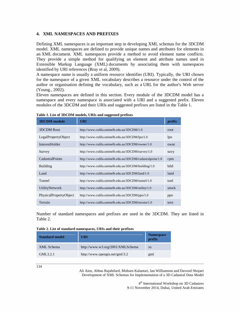
4. XML NAMESPACES AND PREFIXES Defining XML namespaces is an important step in developing XML schemas for the 3DCDM model. XML namespaces are defined to provide unique names and attributes for elements in an XML document. XML namespaces provide a method to avoid element name conflicts. They provide a simple method for qualifying an element and attribute names used in Extensible Markup Language (XML) documents by associating them with namespaces identified by URI references (Bray et al, 2009). A namespace name is usually a uniform resource identifier (URI). Typically, the URI chosen for the namespace of a given XML vocabulary describes a resource under the control of the author or organisation defining the vocabulary, such as a URL for the author's Web server (Young., 2002). Eleven namespaces are defined in this section. Every module of the 3DCDM model has a namespace and every namespace is associated with a URI and a suggested prefix. Eleven modules of the 3DCDM and their URIs and suggested prefixes are listed in the Table 1. Table 1. List of 3DCDM models, URIs and suggested prefixes
3DCDM module URI prefix
3DCDM Root http://www.csdila.unimelb.edu.au/3DCDM/1.0 root
LegalPropertyObject http://www.csdila.unimelb.edu.au/3DCDM/lpo/1.0 lpo
InterestHolder http://www.csdila.unimelb.edu.au/3DCDM/owner/1.0 ownr
Survey http://www.csdila.unimelb.edu.au/3DCDM/survey/1.0 suvy
CadastralPoints http://www.csdila.unimelb.edu.au/3DCDM/cadastralpoint/1.0 cpm
Building http://www.csdila.unimelb.edu.au/3DCDM/building/1.0 bild
Land http://www.csdila.unimelb.edu.au/3DCDM/land/1.0 land
Tunnel http://www.csdila.unimelb.edu.au/3DCDM/tunnel/1.0 tunl
UtilityNetwork http://www.csdila.unimelb.edu.au/3DCDM/utility/1.0 unwk
PhysicalPropertyObject http://www.csdila.unimelb.edu.au/3DCDM/ppo/1.0 ppo
Terrain http://www.csdila.unimelb.edu.au/3DCDM/terrain/1.0 tern
Number of standard namespaces and prefixes are used in the 3DCDM. They are listed in Table 2. Table 2. List of standard namespaces, URIs and their prefixes
Standard model URI Namespace prefix
XML Schema http://www.w3.org/2001/XMLSchema xs
GML3.2.1 http://www.opengis.net/gml/3.2 gml
135 Ali Aien, Abbas Rajabifard, Mohsen Kalantari, Ian Williamson and Davood Shojaei Development of XML Schemas for Implementation of a 3D Cadastral Data Model 4th International Workshop on 3D Cadastres 9-11 November 2014, Dubai, United Arab Emirates
5. XML SCHEMA FOR 3DCDM SUB-MODELS (MODULES) In addition to GML3.2.1’s XML schema, eleven XML schemas are prepared to support implementation of the 3DCDM model. 5.1 XML schema for 3DCDM Root model The Root model consists of core features such as UrbanCadastralModel and components of the 3DCDM. All other models are connected to the root model. The XML namespace of the 3DCDM Root model (module) is defined by the URI http://www.csdila.unimelb.edu.au/3DCDM/1.0. Specifications of the 3DCDM Root model are listed in Table 3. Table 3. Specifications of the 3DCDM Root model
Model name 3DCDM Root
Model description The Root model consists of core features and components of the 3DCDM. All other models are connected to the root.
Model URI http://www.csdila.unimelb.edu.au/3DCDM/1.0
Suggested namespace prefix Root
XML schema file 3DCDMBase.xsd
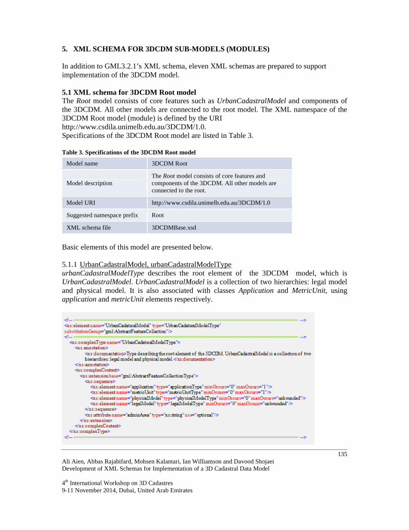
Basic elements of this model are presented below. 5.1.1 UrbanCadastralModel, urbanCadastralModelType urbanCadastralModelType describes the root element of the 3DCDM model, which is UrbanCadastralModel. UrbanCadastralModel is a collection of two hierarchies: legal model and physical model. It is also associated with classes Application and MetricUnit, using application and metricUnit elements respectively.
136 Ali Aien, Abbas Rajabifard, Mohsen Kalantari, Ian Williamson and Davood Shojaei
Development of XML Schemas for Implementation of a 3D Cadastral Data Model
4th International Workshop on 3D Cadastres 9-11 November 2014, Dubai, United Arab Emirates
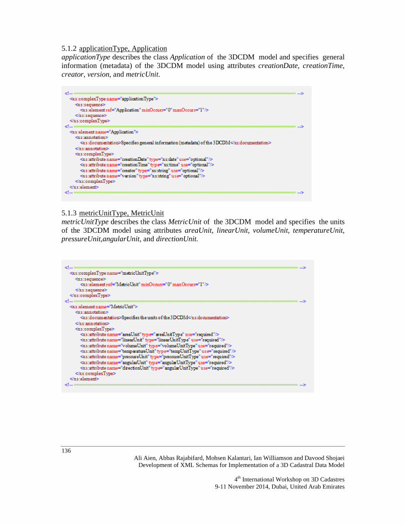
5.1.2 applicationType, Application applicationType describes the class Application of the 3DCDM model and specifies general information (metadata) of the 3DCDM model using attributes creationDate, creationTime, creator, version, and metricUnit.
5.1.3 metricUnitType, MetricUnit metricUnitType describes the class MetricUnit of the 3DCDM model and specifies the units of the 3DCDM model using attributes areaUnit, linearUnit, volumeUnit, temperatureUnit, pressureUnit,angularUnit, and directionUnit.
137 Ali Aien, Abbas Rajabifard, Mohsen Kalantari, Ian Williamson and Davood Shojaei Development of XML Schemas for Implementation of a 3D Cadastral Data Model 4th International Workshop on 3D Cadastres 9-11 November 2014, Dubai, United Arab Emirates
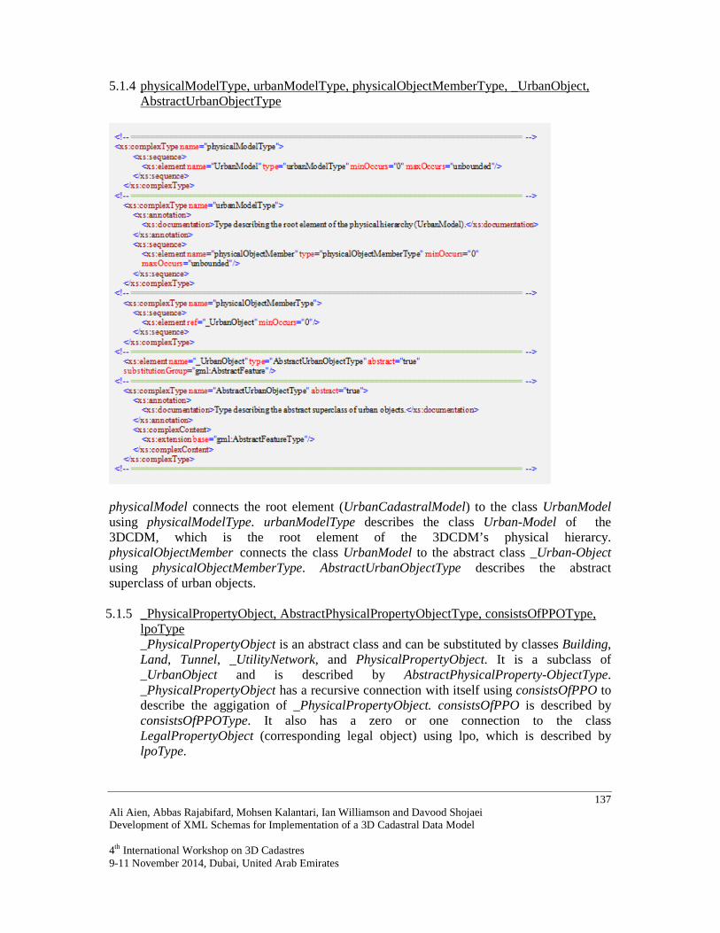
5.1.4 physicalModelType, urbanModelType, physicalObjectMemberType, _UrbanObject, AbstractUrbanObjectType
physicalModel connects the root element (UrbanCadastralModel) to the class UrbanModel using physicalModelType. urbanModelType describes the class Urban-Model of the 3DCDM, which is the root element of the 3DCDM’s physical hierarcy. physicalObjectMember connects the class UrbanModel to the abstract class _Urban-Object using physicalObjectMemberType. AbstractUrbanObjectType describes the abstract superclass of urban objects. 5.1.5 _PhysicalPropertyObject, AbstractPhysicalPropertyObjectType, consistsOfPPOType,
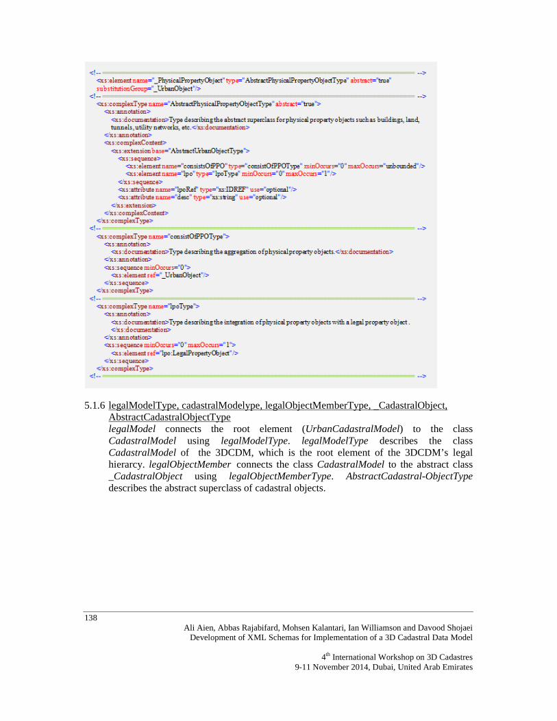
lpoType _PhysicalPropertyObject is an abstract class and can be substituted by classes Building, Land, Tunnel, _UtilityNetwork, and PhysicalPropertyObject. It is a subclass of _UrbanObject and is described by AbstractPhysicalProperty-ObjectType. _PhysicalPropertyObject has a recursive connection with itself using consistsOfPPO to describe the aggigation of _PhysicalPropertyObject. consistsOfPPO is described by consistsOfPPOType. It also has a zero or one connection to the class LegalPropertyObject (corresponding legal object) using lpo, which is described by lpoType.
138 Ali Aien, Abbas Rajabifard, Mohsen Kalantari, Ian Williamson and Davood Shojaei
Development of XML Schemas for Implementation of a 3D Cadastral Data Model
4th International Workshop on 3D Cadastres 9-11 November 2014, Dubai, United Arab Emirates
5.1.6 legalModelType, cadastralModelype, legalObjectMemberType, _CadastralObject, AbstractCadastralObjectType legalModel connects the root element (UrbanCadastralModel) to the class CadastralModel using legalModelType. legalModelType describes the class CadastralModel of the 3DCDM, which is the root element of the 3DCDM’s legal hierarcy. legalObjectMember connects the class CadastralModel to the abstract class _CadastralObject using legalObjectMemberType. AbstractCadastral-ObjectType describes the abstract superclass of cadastral objects.

139 Ali Aien, Abbas Rajabifard, Mohsen Kalantari, Ian Williamson and Davood Shojaei Development of XML Schemas for Implementation of a 3D Cadastral Data Model 4th International Workshop on 3D Cadastres 9-11 November 2014, Dubai, United Arab Emirates
5.2 XML schema for 3DCDM LegalPropertyObject model The LegalPropertyObject model allows creation and representation of all types of legal objects such as land parcels, 3D parcels, ownerships, easements, and common properties in the 3DCDM model. This model also allows association of legal objects to their physical counterparts. The XML namespace of the 3DCDM LegalPropertyObject model (module) is defined by the URI http://www.csdila.unimelb.edu.au/3DCDM/lpo/1.0. Specifications of the 3DCDM Root model are listed in Table 4: Table 4. Specifications of the 3DCDM LegalPropertyObject model
Model name LegalPropertyObject
Model description
The LegalPropertyObject model allows creation and representation of all types of legal objects such as land parcels, 3D parcels, ownerships, easements, and common properties in the 3DCDM. This model also allows association of legal objects to their physical counterparts.
Model URI http://www.csdila.unimelb.edu.au/3DCDM/lpo/1.0
Suggested namespace prefix lpo
XML schema file LegalPropertyObject.xsd

140 Ali Aien, Abbas Rajabifard, Mohsen Kalantari, Ian Williamson and Davood Shojaei
Development of XML Schemas for Implementation of a 3D Cadastral Data Model
4th International Workshop on 3D Cadastres 9-11 November 2014, Dubai, United Arab Emirates
Basic elements of this model are presented below. 5.2.1 LegalPropertyObject, LPOType LPOType describes elements, attributes and associations of the class LegalPropertyObject. address connects LegalPropertyObject to the class Address using addressType. proprietor connects LegalPropertyObject to the class InterestHolder using proprietorType. legalDocument connects LegalPropertyObject to the class Legal-Document using legalDocumentType. MultiCurvePropertyType and MultiSurface-PropertyType represent 2D LegalPropertyObject. SolidPropertyType and MultiSurface-PropertyType represent 3D LegalPropertyObject. BoundarySurfaceType describes the type of surface that is used to define the boundary of the class LegalPropertyObject. address connects LegalPropertyObject to class Address using addressType. ppo connects LegalPropertyObject to the abstract class PhysicalPropertyObject using AbstractPhysicalPropertyObjectType. LegalPropertyObject has a recursive connection with itself using consistsOfLPO to describe the aggigation of LegalPropertyObject. consistsOfLPO is described by consistsOfLPOType. Attributes of the class Legal-PropertyObject are name, lpoFormat, lpoUnit, rrr, lpoClass, area, volume, lot-Entitlement, lotLiability, landUse, lpoState, and ppoRef. 5.2.2 consistsOfLPOType, proprietorType LegalPropertyObject has a recursive connection with itself using consistsOfLPO to describe the aggigation of LegalPropertyObject. consistsOfLPO is described by consistsOfLPOType. proprietor connects LegalPropertyObject to class InterestHolder using proprietorType. 5.2.3 legalDocumentType, Title, titleType legalDocumentType describes the class LegalDocument and connects it to the class Title. Class Title is described by titleType. titleType connects class Title to the title elements using elements locatedAs, refersTo, loan, restrictedBy, managedBy, and property. Attributes of the class Title are volume, folio, securityNo, producedDate, producedTime, angularUnit, and noOfParentTitle. 5.2.4 planDescType, landDescriptionType, parentType, parentTitleType planDescriptionType describes the class LandDescription. landDescriptionType describes the land description of the title using attributes lotNo, planNo, plan, and desc. parentType describes the class ParentTitle. parentTitleType describes the parent title elements using attributes volume and folio. 5.2.5 loanType, mortgageType, encumbranceType, caveatType, managementType,
ownersCorportationsType loanType describes the class Mortgage. mortgageType describes the elements of mortgage using attributes mortgageRef, mortgageType, and bankName. encumbranceType describes the class Caveat. caveatType describes the elements of caveat using attributes caveatRef, caveatDate, and caveator. managementType describes the class OwnersCorporations. ownersCorporationsType describes the elements of owners corporations using attribute ownersCorpPlanNo.

141 Ali Aien, Abbas Rajabifard, Mohsen Kalantari, Ian Williamson and Davood Shojaei Development of XML Schemas for Implementation of a 3D Cadastral Data Model 4th International Workshop on 3D Cadastres 9-11 November 2014, Dubai, United Arab Emirates
5.2.6 BoundarySurfaceType, _BoundaryType, AbstractBoundarySurfaceType BoundarySurfaceType describes the type of surface that is used to define the boundary of class LegalPropertyObject. The type of boundary is specified by the abstract class _BoundaryType. AbstractBoundaryType describes abstract the class _BoundaryType using attributes boundary and desc. MultiSurfacePropertyType represents 2D and 3D LegalPropertyObject. 5.2.7 VirtualSurface, VirtualSurfaceType, WallSurface, WallSurfaceType, FloorSur-face,
FloorSurfaceType, CeilingSurface, CeilingSurfaceType VirtualSurface, WallSuface, FloorSuface, and CeilingSuface describe the type of surface that is used to define the boundary of the class LegalPropertyObject. They are described by VirtualSurfaceType, WallSurfaceType, FloorSurfaceType, and CeilingSur-faceType respectively. 5.2.8 RoofSurface, RoofSurfaceType, SlabSurface, SlabSurfaceType,
Suspected-CeilingSurface, SuspectedCeilingSurfaceType, FloorJoistsSurface, FloorJoists-SurfaceType
RoofSurface, SlabSurface, SuspectedCeilingSurface, and FloorJoistsSurface describe the type of surface that is used to define the boundary of class LegalPropertyObject. They are described by RoofSurfaceType, SlabSurfaceType, SuspectedCeilingType, and FloorJoists-SurfaceType respectively. 5.3 XML schema for 3DCDM InterestHolder model The InterestHolder model maintains information about the land interest holder. This model has an association with the LegalPropertyObject model. The XML namespace of the 3DCDM InterestHolder model (module) is defined by the URI http://www.csdila.unimelb.edu.au/3DCDM/owner/1.0. Specifications of the 3DCDM InterestHolder model are listed in Table 5. Table 5. Specifications of the 3DCDM InterestHolder model
Model name InterestHolder
Model description
The InterestHolder model maintains information about the land interest holder. This model has an association with the LegalPropertyObject model.
Model URI http://www.csdila.unimelb.edu.au/3DCDM/owner/1.0
Suggested namespace prefix ownr
XML schema file InterestHolder.xsd
Basic elements of this model are presented below.
142 Ali Aien, Abbas Rajabifard, Mohsen Kalantari, Ian Williamson and Davood Shojaei
Development of XML Schemas for Implementation of a 3D Cadastral Data Model
4th International Workshop on 3D Cadastres 9-11 November 2014, Dubai, United Arab Emirates
5.3.1 InterestHolder, interestHolderType interestHolderType describes the elements, attributes, and associations of proprietors using attributes pName, share, and type. 5.3.2 legalDocumentType, propertyType legalDocumentType describes the elements, attributes, and associations of proprietors using attributes pName, share, and type. propertyType connects the interest holder to the property object, which is LegalPropertyObject. 5.3.3 addressType, geocodedAddressType, addressPointType addressType describes the elements, attributes, and associations of the class Address using approperiate attributes. A geocoded address is described by geocodedAddress-Type and addressPointType. 5.4 XML schema for 3DCDM Survey model The Survey model maintains technical and administrative information of surveying and of the surveyor. The XML namespace of the 3DCDM Survey model (module) is defined by the URI http://www.csdila.unimelb.edu.au/3DCDM/survey/1.0. Specifications of the 3DCDM Survey model are listed in Table 6. Table 6. Specifications of the 3DCDM Survey model
Model name Survey
Model description The Survey model maintains technical and administrative information of surveying and surveyor.
Model URI http://www.csdila.unimelb.edu.au/3DCDM/survey/1.0
Suggested namespace prefix suvy
XML schema file Survey.xsd
Basic elements of this model are presented below. 5.4.1 Survey, surveyType surveyType describes the elements, attributes, and associations of the class Survey using attributes jurisdiction, legislation, purposeofSurvey, surveyDate, surveyFormat, method, fieldNoteRef, and desc. 5.4.2 surveyedByType, surveyorType surveyedByType describes the class Surveyor. surveyorType describes the surveyor information using attributes name, regNumber, and surveyorFirm. 5.4.3 initialisationType, setupInstrumentType, referencePointType, setupPointType initialisationType connects the class Survey to class SetupInstrument. setupInstrumentType describes the class SetupInstrument using attributes setupID, stationName, and instrumentHeight. referencePointType connects the class Setup-Instrument to the class SetupPoint. SetupPointType describes the class SetupPoint using element pntRef.

143 Ali Aien, Abbas Rajabifard, Mohsen Kalantari, Ian Williamson and Davood Shojaei Development of XML Schemas for Implementation of a 3D Cadastral Data Model 4th International Workshop on 3D Cadastres 9-11 November 2014, Dubai, United Arab Emirates
5.4.4 observationType, observationGroupType observationType connects the class Survey to the class ObservationGroup. Observation-GroupType describes the type of observation that is used for surveying. 5.4.5 reducedLineObservationType, redHorizontalLineObservationType reducedLineObservationType connects the class ObservationGroup to the class red-HorizontalLineObservation. redHorizontalLineObservationType describes the elements and attributes of class redHorizontalLineObservation. 5.4.6 reducedArcObservationType, redHorizontalArcObservationType reducedArcObservationType connects the class ObservationGroup to the class red-HorizontalArcObservation. redHorizontalArcObservationType describes the elements and attributes of the class redHorizontalArcObservation. 5.5 XML schema for 3DCDM CadastralPoints model The CadastralPoints model maintains the information related to the survey permanent marks. The XML namespace of the 3DCDM CadastralPoints model (module) is defined by the URI http://www.csdila.unimelb.edu.au/3DCDM/survey/1.0. Specifications of the 3DCDM CadastralPoints model are listed in Table 7. Table 7. Specifications of the 3DCDM CadastralPoints model
Model name CadastralPoints
Model description The CadastralPoints model maintains the information related to the survey permanent marks.
Model URI http://www.csdila.unimelb.edu.au/3DCDM/cadastralpoint/1.0
Suggested namespace prefix cpm
XML schema file CadastralPoint.xsd
Basic elements of this model are presented below. 5.5.1 CadastralPoints, cadastralPointsType cadastralPointsType describes the elements, attributes, and associations of cadastral points. 5.5.2 referencePointMemberType, cadastralPointType referencePointMemberType and cadastralPointType describe the elements, attributes, and associations of a cadastral point. 5.6 XML schema for 3DCDM Building model The Building model allows the creation and representation of various building parts and building structures. This model has an association with the LegalPropertyObject model. The XML namespace of the 3DCDM Building model (module) is defined by the URI http://www.csdila.unimelb.edu.au/3DCDM/building/1.0. Specifications of the 3DCDM Building model are listed in Table 8.
144 Ali Aien, Abbas Rajabifard, Mohsen Kalantari, Ian Williamson and Davood Shojaei
Development of XML Schemas for Implementation of a 3D Cadastral Data Model
4th International Workshop on 3D Cadastres 9-11 November 2014, Dubai, United Arab Emirates
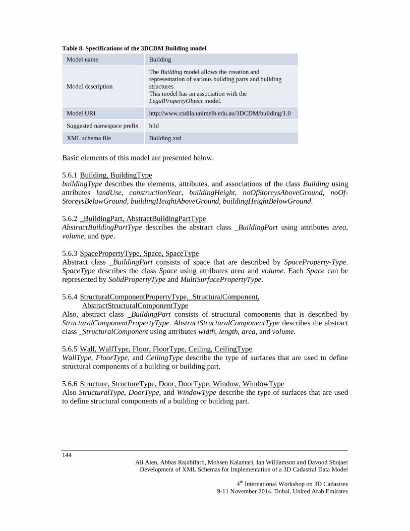
Table 8. Specifications of the 3DCDM Building model
Model name Building
Model description
The Building model allows the creation and representation of various building parts and building structures. This model has an association with the LegalPropertyObject model.
Model URI http://www.csdila.unimelb.edu.au/3DCDM/building/1.0
Suggested namespace prefix bild
XML schema file Building.xsd
Basic elements of this model are presented below. 5.6.1 Building, BuildingType buildingType describes the elements, attributes, and associations of the class Building using attributes landUse, constructionYear, buildingHeight, noOfStoreysAboveGround, noOf-StoreysBelowGround, buildingHeightAboveGround, buildingHeightBelowGround. 5.6.2 _BuildingPart, AbstractBuildingPartType AbstractBuildingPartType describes the abstract class _BuildingPart using attributes area, volume, and type. 5.6.3 SpacePropertyType, Space, SpaceType Abstract class _BuildingPart consists of space that are described by SpaceProperty-Type. SpaceType describes the class Space using attributes area and volume. Each Space can be represented by SolidPropertyType and MultiSurfacePropertyType. 5.6.4 StructuralComponentPropertyType,_StructuralComponent,
AbstractStructuralComponentType Also, abstract class _BuildingPart consists of structural components that is described by StructuralComponentPropertyType. AbstractStructuralComponentType describes the abstract class _StructuralComponent using attributes width, length, area, and volume. 5.6.5 Wall, WallType, Floor, FloorType, Ceiling, CeilingType WallType, FloorType, and CeilingType describe the type of surfaces that are used to define structural components of a building or building part. 5.6.6 Structure, StructureType, Door, DoorType, Window, WindowType Also StructuralType, DoorType, and WindowType describe the type of surfaces that are used to define structural components of a building or building part.

145 Ali Aien, Abbas Rajabifard, Mohsen Kalantari, Ian Williamson and Davood Shojaei Development of XML Schemas for Implementation of a 3D Cadastral Data Model 4th International Workshop on 3D Cadastres 9-11 November 2014, Dubai, United Arab Emirates
5.6.7 Unit, UnitType, CarPark, CarParkType, ServiceRoom, ServiceRoomType, StorageRoom, StorageRoomType
UnitType, CarParkType, ServiceRoomType, and StorageRoomType describe the type of building parts. 5.6.8 Pathway, PathwayType, Balcony, BalconyType, Roof, RoofType, BuildingPart,
BuildingPartType PathwayType, BalconyType, RoofType, and BuildingPartType also describe the type of building parts. 5.7 XML schema for 3DCDM Land model The land model allows the creation and representation of the physical land object. This model has an association with the LegalPropertyObject model. The XML namespace of the 3DCDM Land model (module) is defined by the URI http://www.csdila.unimelb.edu.au/3DCDM/land/1.0. Specifications of the 3DCDM Land model are listed in Table 9. Table 9. Specifications of the 3DCDM Land model
Model name Land
Model description
The land model allows the creation and representation of the physical land object. This model has an association with the LegalPropertyObject model.
Model URI http://www.csdila.unimelb.edu.au/3DCDM/land/1.0
Suggested namespace prefix land
XML schema file Land.xsd
5.8 XML schema for 3DCDM Tunnel model The Tunnel model allows the creation and representation of various parts and structures of a tunnel. This model has an association with the LegalPropertyObject model. The XML namespace of the 3DCDM Tunnel model (module) is defined by the URI http://www.csdila.unimelb.edu.au/3DCDM/tunnel/1.0. Specifications of the 3DCDM Tunnel model are listed in Table 10. Table 10. Specifications of the 3DCDM Tunnel model
Model name Tunnel
Model description
The Tunnel model allows the creation and representation of various parts and structures of a tunnel. This model has an association with the LegalPropertyObject model.
Model URI http://www.csdila.unimelb.edu.au/3DCDM/tunnel/1.0
Suggested namespace prefix tunl
XML schema file Tunnel.xsd

146 Ali Aien, Abbas Rajabifard, Mohsen Kalantari, Ian Williamson and Davood Shojaei
Development of XML Schemas for Implementation of a 3D Cadastral Data Model
4th International Workshop on 3D Cadastres 9-11 November 2014, Dubai, United Arab Emirates
5.9 XML schema for 3DCDM UtilityNetwork model The UtilityNetwork model allows the creation and representation of various parts and components of a utility network. This model has an association with the LegalPropertyObject model. The XML namespace of the 3DCDM UtilityNetwork model (module) is defined by the URI http://www.csdila.unimelb.edu.au/3DCDM/utility/1.0. Specifications of the 3DCDM UtilityNetwork model are listed in Table 11. Table 11. Specifications of the 3DCDM UtilityNetwork model
Model name UtilityNetwork
Model description
The UtilityNetwork model allows the creation and representation of various parts and components of a utility network. This model has an association with the LegalPropertyObject model.
Model URI http://www.csdila.unimelb.edu.au/3DCDM/utility/1.0
Suggested namespace prefix unwk
XML schema file UtilityNetwork.xsd
5.10 XML schema for 3DCDM PhysicalPropertyObject model The PhysicalPropertyObject model allows the creation and representation of various unknown physical objects in the 3DCDM. This model has an association with the LegalPropertyObject model. The XML namespace of the 3DCDM PhysicalProperty-Object model (module) is defined by the URI http://www.csdila.unimelb.edu.au/3DCDM/ppo/1.0. Specifications of the 3DCDM PhysicalPropertyObject model are listed in Table 12. Table 12. Specifications of the 3DCDM PhysicalPropertyObject model
Model name PhysicalPropertyObject
Model description
The PhysicalPropertyObject model allows creation and representation of various unknown physical objects in the 3DCDM. This model has an association with the LegalPropertyObject model.
Model URI http://www.csdila.unimelb.edu.au/3DCDM/ppo/1.0
Suggested namespace prefix ppo
XML schema file PhysicalPropertyObject.xsd
5.11 XML schema for 3DCDM Terrain model The Terrain model allows creation and representation of the ground surface (TIN or DEM) in the 3DCDM. The XML namespace of the 3DCDM Terrain model (module) is defined by the URI http://www.csdila.unimelb.edu.au/3DCDM/terrain/1.0. Specifications of the 3DCDM Terrain model are listed in Table 13.

147 Ali Aien, Abbas Rajabifard, Mohsen Kalantari, Ian Williamson and Davood Shojaei Development of XML Schemas for Implementation of a 3D Cadastral Data Model 4th International Workshop on 3D Cadastres 9-11 November 2014, Dubai, United Arab Emirates
Table 13. Specifications of the 3DCDM Terrain model
Model name Terrain
Model description The Terrain model allows creation and representation of the ground surface (TIN or DEM) in the 3DCDM.
Model URI http://www.csdila.unimelb.edu.au/3DCDM/terrain/1.0
Suggested namespace prefix tern
XML schema file Terrain.xsd
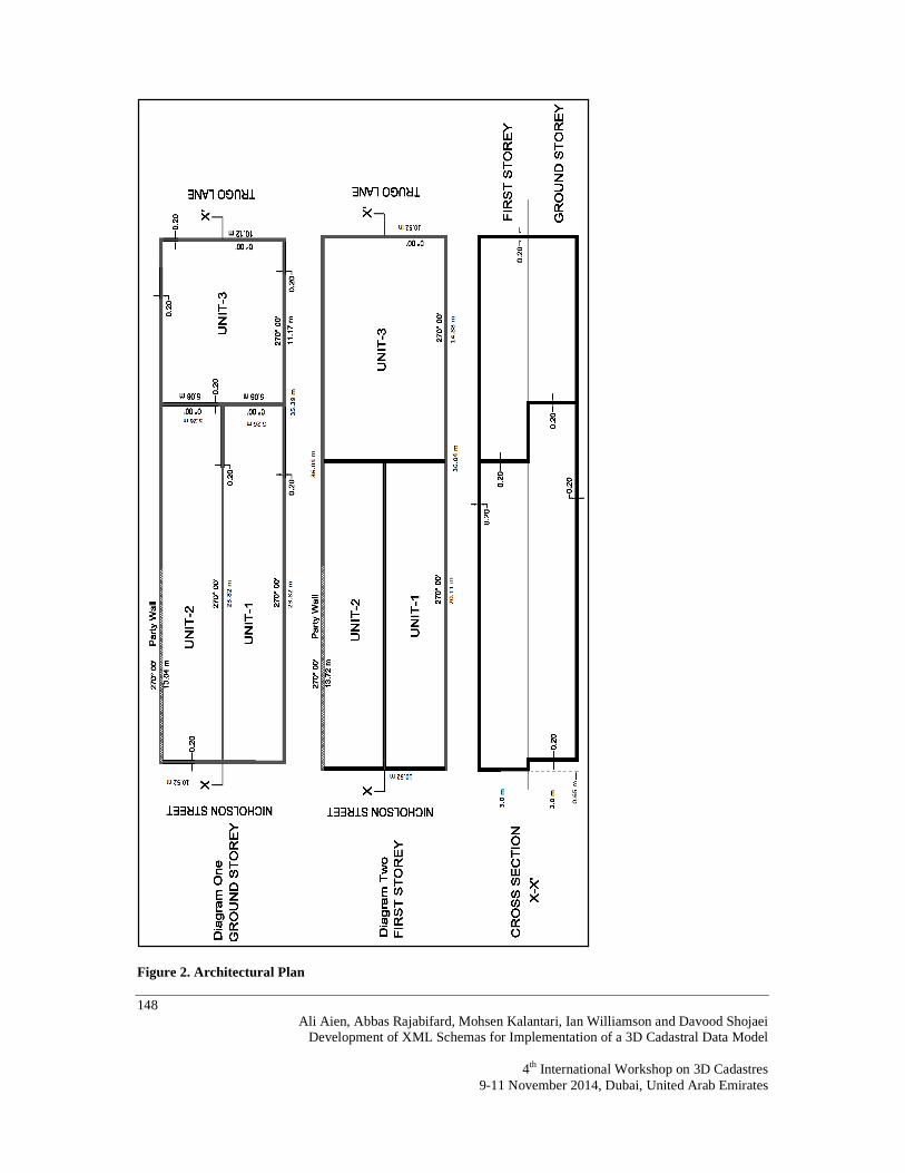
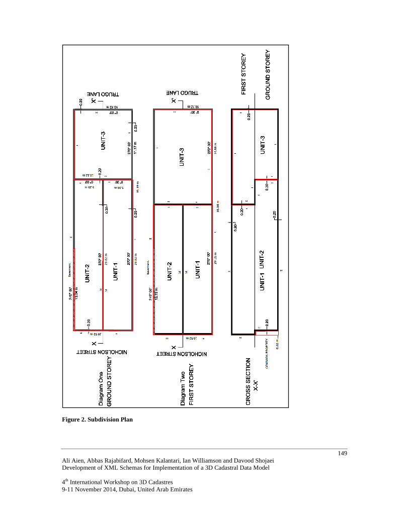
6. EXAMPLE OF A 3DCDM DATASET This section illustrates how the 3DCDM model is implemented. A two-storey building consists of three units, one common property, and one easement is chosen as a case study. Figure 2 shows the architectural plan of the building including the location of units and walls’ length and width. Figure 3 shows the corresponding legal objects, which are usually represented in subdivision plans. The following sections provide an overview of the case study and related 3DCDM instance documents. 6.1 Dataset The case study is a two-storey building above ground surface. Each story has 3.0 metre height and the building’s total height is 6.0 meters. The walls’ width are 0.20 meters. Part of Unit-2’s wall is a party-wall and then it is considered an easement for this unit. Cross-section X-X’ represents how the units are vertically located. Part of the building’s entrance on the ground floor is a common property with a width of 0.65 metres. The beneficiaries of the common property are Unit-1 and Unit-2. Unit-3’s street access is from Trugo Lane. The ownership boundary between Unit-1 and Unit-2 is the median, symbolised by ‘M’ in Figure 3. Thus, the wall between Unit-1 and Unit-2 is not a common property. The ownership boundary between Unit-1 and Unit-3 and also Unit-2 and Unit-3 is represented by symbol ‘I’, which means that the ownership boundary is located in the interior facing wall between Unit-1, Unit-2, and Unit-3. Therefore the wall between Unit-1 and Unit-3 and also Unit-2 and Unit-3 is common property. Other ownership boundaries of Unit-1 and Unit-2 are represented by symbol ‘E’, which means ownership boundaries are the exterior surface of the wall. Therefore, the building façade in front of Nicholson Street belongs to Unit-1 and Unit-2. All other boundaries of Unit-3 are interior boundaries. This means the building façade in front of Trugo Lane does not belong to Unit-1 and Unit-2.
148 Ali Aien, Abbas Rajabifard, Mohsen Kalantari, Ian Williamson and Davood Shojaei
Development of XML Schemas for Implementation of a 3D Cadastral Data Model
4th International Workshop on 3D Cadastres 9-11 November 2014, Dubai, United Arab Emirates
Figure 2. Architectural Plan
149 Ali Aien, Abbas Rajabifard, Mohsen Kalantari, Ian Williamson and Davood Shojaei Development of XML Schemas for Implementation of a 3D Cadastral Data Model 4th International Workshop on 3D Cadastres 9-11 November 2014, Dubai, United Arab Emirates
Figure 2. Subdivision Plan

150 Ali Aien, Abbas Rajabifard, Mohsen Kalantari, Ian Williamson and Davood Shojaei
Development of XML Schemas for Implementation of a 3D Cadastral Data Model
4th International Workshop on 3D Cadastres 9-11 November 2014, Dubai, United Arab Emirates
An arbitrary coordinate system is defined to extract all coordinates of the points. The origin of the coordinate system is at the lower left corner of the first story (X = 1000 m, Y = 1000 m) where the X-axis is parallel to the map’s horizontal axis and the Y-axis is perpendicular to the X-axis. As a result, all vertices in the plans have known coordinates. From these coordinates, various properties such as width and length of the walls and units can be found. The following sections represent how an instance of 3DCDM is created to model the legal and physical objects of a 3D building. This example and all XML schemas are edited with XMLSpy v2011 rel. 3 (http://www.altova.com). 6.2 Select and import related modules The aim of this practice is to model the 3D legal object of the building and their physical counterparts. The first step of using the 3DCDM is to select the modules that are required for the application. Based on the available dataset, the following modules are required to import in the file GML3.2.1, Building, LegalpropertyObject, InterestHolder, Survey, Cadastral-Points, and Terrain schemas are selected for this practice.
Project name, coordinate reference system, project boundary, author information (application), and measurement units are specified in the next step.

151 Ali Aien, Abbas Rajabifard, Mohsen Kalantari, Ian Williamson and Davood Shojaei Development of XML Schemas for Implementation of a 3D Cadastral Data Model 4th International Workshop on 3D Cadastres 9-11 November 2014, Dubai, United Arab Emirates
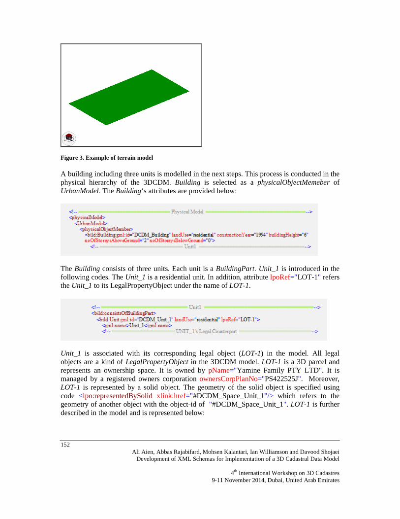
Combination of terrain and land ownership right objects provides more realistic re-presentation of the legal world. Therefore, the terrain model (TIN) is provided in the first step as below:
The terrain model can be visualised in Figure 4 using FZK Viewer (http://www.iai.fzk.de/www-extern/index.php?id=222&L=1). For this purpose, the 3DCDM’s elements are converted to the CityGML elements. FZK Viewer is a CityGML (http://www.citygml.org/) and IFC (http://www.buildingsmart.org/standards/ifc) viewer.
152 Ali Aien, Abbas Rajabifard, Mohsen Kalantari, Ian Williamson and Davood Shojaei
Development of XML Schemas for Implementation of a 3D Cadastral Data Model
4th International Workshop on 3D Cadastres 9-11 November 2014, Dubai, United Arab Emirates
Figure 3. Example of terrain model A building including three units is modelled in the next steps. This process is conducted in the physical hierarchy of the 3DCDM. Building is selected as a physicalObjectMemeber of UrbanModel. The Building‘s attributes are provided below:
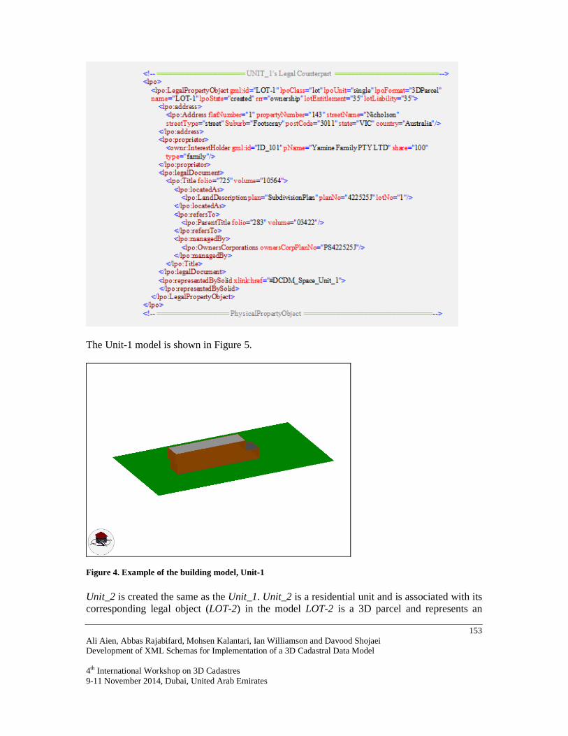
The Building consists of three units. Each unit is a BuildingPart. Unit_1 is introduced in the following codes. The Unit_1 is a residential unit. In addition, attribute lpoRef="LOT-1" refers the Unit_1 to its LegalPropertyObject under the name of LOT-1.
Unit_1 is associated with its corresponding legal object (LOT-1) in the model. All legal objects are a kind of LegalPropertyObject in the 3DCDM model. LOT-1 is a 3D parcel and represents an ownership space. It is owned by pName="Yamine Family PTY LTD". It is managed by a registered owners corporation ownersCorpPlanNo="PS422525J". Moreover, LOT-1 is represented by a solid object. The geometry of the solid object is specified using code <lpo:representedBySolid xlink:href="#DCDM_Space_Unit_1"/> which refers to the geometry of another object with the object-id of "#DCDM_Space_Unit_1". LOT-1 is further described in the model and is represented below:
153 Ali Aien, Abbas Rajabifard, Mohsen Kalantari, Ian Williamson and Davood Shojaei Development of XML Schemas for Implementation of a 3D Cadastral Data Model 4th International Workshop on 3D Cadastres 9-11 November 2014, Dubai, United Arab Emirates
The Unit-1 model is shown in Figure 5.
Figure 4. Example of the building model, Unit-1
Unit_2 is created the same as the Unit_1. Unit_2 is a residential unit and is associated with its corresponding legal object (LOT-2) in the model LOT-2 is a 3D parcel and represents an

154 Ali Aien, Abbas Rajabifard, Mohsen Kalantari, Ian Williamson and Davood Shojaei
Development of XML Schemas for Implementation of a 3D Cadastral Data Model
4th International Workshop on 3D Cadastres 9-11 November 2014, Dubai, United Arab Emirates
ownership space. It is owned by pName="Jude Sammonds". LOT-2 is represented by a solid object. The geometry of the solid object is specified using code <lpo:representedBySolid xlink:href="#DCDM_Space_Unit_2"/>, which refers to the geometry of another object with the object id of "#DCDM_Space_Unit_2". The following codes (shortened codes) describe how Unit-2 is modelled in the 3DCDM model. The Unit-1, Unit-1, and Unit-3 models are shown in Figure 6.
Figure 5. Example of the building model, Unit-1, Unit-2, and Unit3
Figure 7 illustrates the legal counterparts of the building’s units. In this Figure, the wall between the Unit-1 and Unit-3 and also Unit-2 and Unit-3 is common property, and it does not belong to the units.
Unit-1 Unit-2
Unit-3

155 Ali Aien, Abbas Rajabifard, Mohsen Kalantari, Ian Williamson and Davood Shojaei Development of XML Schemas for Implementation of a 3D Cadastral Data Model 4th International Workshop on 3D Cadastres 9-11 November 2014, Dubai, United Arab Emirates
Figure 6. Example of the building model, Unit-1, Unit-2, and Unit3
The previous methods are used to model the Unit-3 as well. Using the above codes, three units of the Building and their legal counterparts are modelled in the 3DCDM. The common property and easement are visualised in the Figure 8.
Figure 7. Example of the building model, common property and easement
Unit-1 and Unit-2 Unit-3
Common property

156 Ali Aien, Abbas Rajabifard, Mohsen Kalantari, Ian Williamson and Davood Shojaei
Development of XML Schemas for Implementation of a 3D Cadastral Data Model
4th International Workshop on 3D Cadastres 9-11 November 2014, Dubai, United Arab Emirates
7. CONCLUSION In this paper, the physical model of the 3DCDM was presented as the fourth step of 3D cadastral data-modelling development cycle. This step is the last step of the 3DCDM model development. The aim was to implement the 3DCDM model. For this purpose, eleven XML schemas were developed. One XML namespace, one unique prefix, and one URI were defined per each XML modules. They are summarized in the Table 1. URIs help the model users to access the XML schemas and utilize them to populate their datasets into the XML schemas. A practical example of a 3DCDM dataset was presented to evaluate how the 3DCDM models the physical objects of a building and their legal counterparts. The dataset is a building that consists of three units, two common properties, and one easement. REFERENCES Aien, A. (2013). 3D Cadastral Data Modelling. PhD, University of Melbourne. Aien, A., Kalantari, M., Rajabifard, A., Williamson, I., & Bennett, R. (2013a). Utilising Data Modelling to Understand the Structure of 3D Cadastres. Journal of Spatial Science, 58(2), 215-234. Aien, A., Kalantari, M., Rajabifard, A., williamson, I., & Wallace, J. (2013b). Towards integration of 3D legal and physical objects in cadastral data models. Land Use Policy, 35, 140-154. Aien, A., Kalantari, M., Rajabifard, A., Williamson, I. P., & Bennett, R. (2011). Advanced Principles of 3D Cadastral Data Modelling. Paper presented at the 2nd International Workshop on 3D Cadastres Proceeding, Delft, The Netherlands. Bray, T., Hollander, D., Layman, A., Tobin, R., & Thompson, H. S. (2009). Namespaces in XML 1.0. W3C Recommendation from http://www.w3.org/TR/REC-xml-names/ ISO19136. (2007). Geographic information - Geography Markup Language (GML) (pp. 394): ISO. LiquidTechnologies. (2012). XML Schema Tutorial Retrieved 10/11/2012, 2012, from http://www.liquid-technologies.com/Tutorials/XmlSchemas/XsdTutorial_01.aspx Shojaei, D., Rajabifard, A., Kalantari, M., Bishop, I. D., & Aien, A. (2012). Development of a 3D ePlanLandXML Visualisation System in Australia. Paper presented at the the 3rd International Workshop on 3D Cadastres: Developments and Practices, Shenzhen, China. W3C. (2010). XML Schema. Retrieved 25/10/2012, 2012, from http://www.w3.org/standards/xml/schema Young., M. J. (2002). XML step by step (2nd ed.). Redmond, Wash.: Microsoft Press.

157 Ali Aien, Abbas Rajabifard, Mohsen Kalantari, Ian Williamson and Davood Shojaei Development of XML Schemas for Implementation of a 3D Cadastral Data Model 4th International Workshop on 3D Cadastres 9-11 November 2014, Dubai, United Arab Emirates
BIOGRAPHICAL NOTES Ali Aien finished his PhD on 3D cadastral data modeling in 2013 at the Department of Infrastructure Engineering, the University of Melbourne. His research aimed to develop and implement a data model to enable the capture, storage, editing, querying, analysis and support visualization of 3D land rights, restrictions and responsibilities in cadastre. He is currently working as a research assistant in the Centre for Spatial Data Infrastructures & Land Administration (CSDILA). Abbas Rajabifard is a Professor and Head of Department of Infrastructure Engineering at The University of Melbourne. He is also Director of the Centre for Spatial Data Infrastructures & Land Administration (CSDILA). He is former President of the GSDI Association, a member of ICA-Spatial Data Standard Commission, and a member of Victorian Spatial Council. Mohsen Kalantari is a Research Fellow at the Centre for SDIs and Land Administration at the Department of Geomatics, the University of Melbourne working on 3D cadastre. He finished his PhD from the University of Melbourne in 2008. Ian Williamson’s teaching and research is concerned with cadastral, land and geographic information systems, land administration and spatial data infrastructures, in both developed and developing countries. He has published extensively on these topics. He has undertaken research or consultancies world-wide including for AusAID, the United Nations and the World Bank. He is a Member of the Order of Australia (AM), a Fellow of the Academy of Technological Sciences and Engineering Australia (FTSE), a Fellow of the Institution of Surveyors Australia Inc., a Fellow of the Institution of Engineers Australia, a Fellow of the Royal Institution of Chartered Surveyors, an Honorary Fellow of the Mapping Sciences Institute, Australia and an Honorary Member of the International Federation of Surveyors (FIG). He was Chairperson of FIG Commission 7 (Cadastre and Land Management) 1994–98 and Director United Nations Liaison for the FIG from 1998–2002. He was a member of the Executive and Chair, Working Group 3 (Cadastre), UN sponsored Permanent Committee on GIS Infrastructures for Asia and the Pacific (2001–2009). At Melbourne he has been President of the Academic Board and Pro-Vice-Chancellor, and was Head of the Department of Geomatics (1987–1993, 1998–2007) and works closely with the Centre for Spatial Data Infrastructures and Land Administration. Awarded the Centenary Medal by the Prime Minister for service to Australian society in research and geomatics engineering and surveying 2003. Davood Shojaei started his PhD on 3D Cadastral Visualisation in 2010 at the Centre for SDIs and Land Administration at the Department of Infrastructure Engineering, the University of Melbourne. His research aims to develop 3D cadastral visualisation requirements and implement some prototype systems to represent 3D land rights, restrictions and responsibilities in cadastre.
158 Ali Aien, Abbas Rajabifard, Mohsen Kalantari, Ian Williamson and Davood Shojaei
Development of XML Schemas for Implementation of a 3D Cadastral Data Model
4th International Workshop on 3D Cadastres 9-11 November 2014, Dubai, United Arab Emirates
CONTACTS Ali Aien University of Melbourne Parkville Victoria AUSTRALIA 3010 Tel.: +61 3 8344 6771 E-mail: [email protected]; [email protected] Website: http://www.csdila.unimelb.edu.au/people/ali-aien.html Abbas Rajabifard University of Melbourne Parkville Victoria AUSTRALIA 3010 Tel.: +61 3 8344 0234 E-mail: [email protected] WebsiteL: http://www.csdila.unimelb.edu.au/people/abbas-rajabifard.html Mohsen Kalantari University of Melbourne Parkville Victoria AUSTRALIA 3010 Tel.: +61 3 8344 6833 [email protected] http://www.csdila.unimelb.edu.au/people/saeid-kalantari-soltanieh.html Ian Williamson AM University of Melbourne Parkville Victoria AUSTRALIA 3010 +61 3 8344 5597 [email protected] http://www.csdila.unimelb.edu.au/people/ian-williamson.html Davood Shojaei University of Melbourne Parkville Victoria AUSTRALIA 3010 Tel.: +61 3 8344 5597 E-mail: [email protected] Website: http://www.csdila.unimelb.edu.au/people/davood-shojaei.html