development of thermoplastic pultrusion with modeling and ... · development of thermoplastic...
TRANSCRIPT

Development of Thermoplastic Pultrusion with Modeling and Experiments
Khongor Jamiyanaa and Uday Vaidya University of Alabama at Birmingham (UAB)
GATE Scholar Project ID: LM085
Project No: DE-EE-0005580 Program Manager: Adrienne Riggi
This presentation does not contain any proprietary or confidential information

Project Summary* (The budget below represents the entire GATE Center. This
presentation is only a sub-set of the DOE GATE effort.) Barriers • Limited information on
advanced materials database
• Lack of high temperature properties
Partners • ORNL • MIT- RCF • Owens Corning • Polystrand, PPG • CIC, Canada
Budget (Overall GATE Center) Total project: $750,000* DOE portion: $600,000 University Cost Share: $150,000 $447,420 DOE $325,000 Expended 72.6% complete
Timeline Project Start - Oct 2011 Project End – Sep 2016 72.6 % complete

Khongor Jamiyanaa (GATE Scholar) - Background
• Graduated from Colorado State Univ. in 2010
• BS in Mechanical Engineering, Minor in Mathematics
• Graduated from Univ. of Alabama at Birmingham in 2014
• MS in Materials Science and Engineering
• Research Thesis: Design and modeling of Thermoplastic Pultrusion Process
• 1yr Co-op internship at Owens Corning Science & Technology center in 2013.
• Application Development Engineer
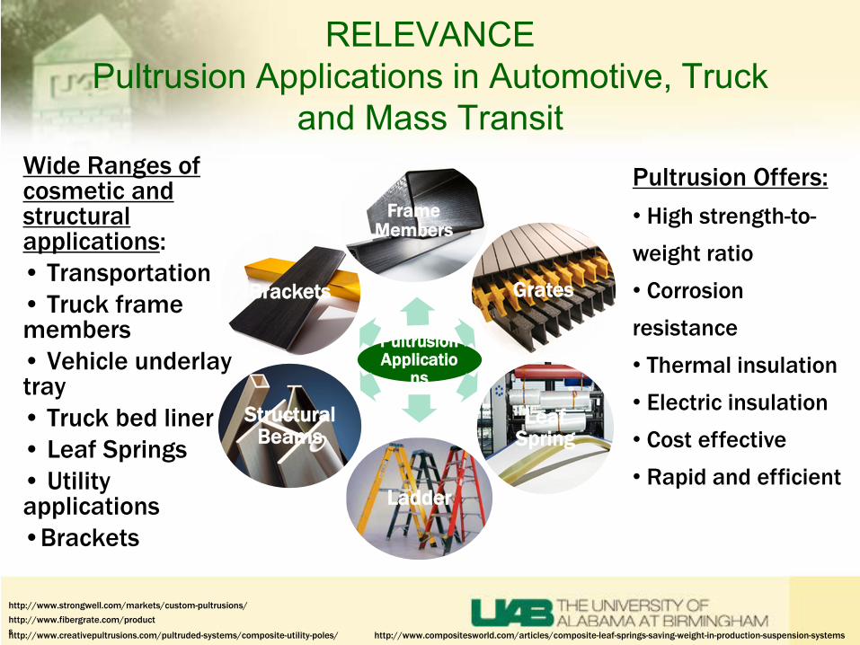
RELEVANCE Pultrusion Applications in Automotive, Truck
and Mass Transit
Pultrusion Applicatio
ns
Frame Members
Grates
Leaf Spring
Ladder
Structural Beams
Brackets
Wide Ranges of cosmetic and structural applications: • Transportation • Truck frame members • Vehicle underlay tray • Truck bed liner • Leaf Springs • Utility applications •Brackets
http://www.creativepultrusions.com/pultruded-systems/composite-utility-poles/
http://www.fibergrate.com/products
Pultrusion Offers: • High strength-to-weight ratio • Corrosion resistance • Thermal insulation • Electric insulation • Cost effective • Rapid and efficient
http://www.strongwell.com/markets/custom-pultrusions/
http://www.compositesworld.com/articles/composite-leaf-springs-saving-weight-in-production-suspension-systems
RELEVANCE GATE Project
• Technique to produce fiber reinforced polymer (FRP) composites of a profiled shape.
• FRP material pulled through a temperature controlled die to shape the material.
•Highly aligned, constant cross-section, linear length, continuously pulled.
•Both thermosets and thermoplastics can be pultruded, the process slightly differ.
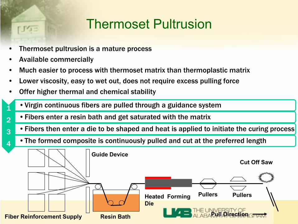
Thermoset Pultrusion
• Thermoset pultrusion is a mature process • Available commercially • Much easier to process with thermoset matrix than thermoplastic matrix • Lower viscosity, easy to wet out, does not require excess pulling force • Offer higher thermal and chemical stability
Fiber Reinforcement Supply
Guide Device
Resin Bath
Heated Forming Die
Pullers Pullers
Cut Off Saw
Pull Direction
1 •Virgin continuous fibers are pulled through a guidance system
2 •Fibers enter a resin bath and get saturated with the matrix
3 •Fibers then enter a die to be shaped and heat is applied to initiate the curing process
4 •The formed composite is continuously pulled and cut at the preferred length
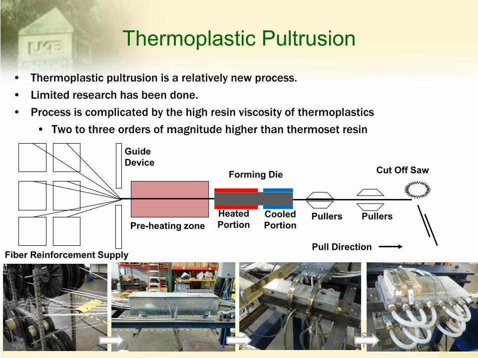
Thermoplastic Pultrusion
• Thermoplastic pultrusion is a relatively new process. • Limited research has been done. • Process is complicated by the high resin viscosity of thermoplastics
• Two to three orders of magnitude higher than thermoset resin
Fiber Reinforcement Supply
Guide Device
Pre-heating zone Heated Portion
Pullers Pullers
Cut Off Saw
Cooled Portion
Pull Direction
Forming Die
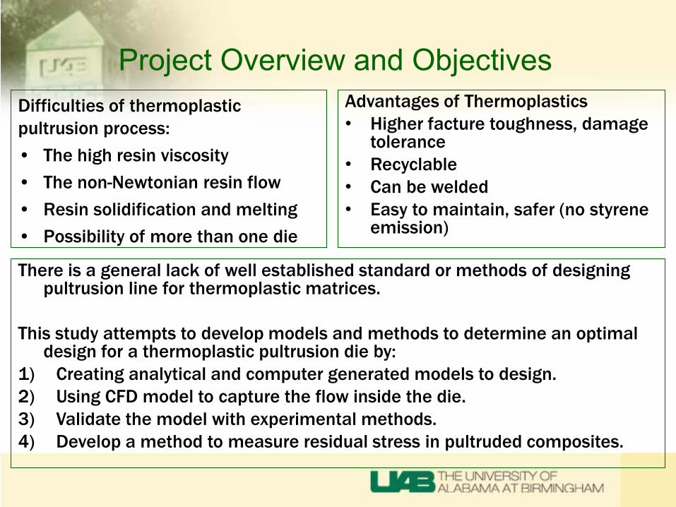
Project Overview and Objectives Difficulties of thermoplastic pultrusion process: • The high resin viscosity • The non-Newtonian resin flow • Resin solidification and melting • Possibility of more than one die
Advantages of Thermoplastics • Higher facture toughness, damage
tolerance • Recyclable • Can be welded • Easy to maintain, safer (no styrene
emission)
There is a general lack of well established standard or methods of designing pultrusion line for thermoplastic matrices.
This study attempts to develop models and methods to determine an optimal
design for a thermoplastic pultrusion die by: 1) Creating analytical and computer generated models to design. 2) Using CFD model to capture the flow inside the die. 3) Validate the model with experimental methods. 4) Develop a method to measure residual stress in pultruded composites.
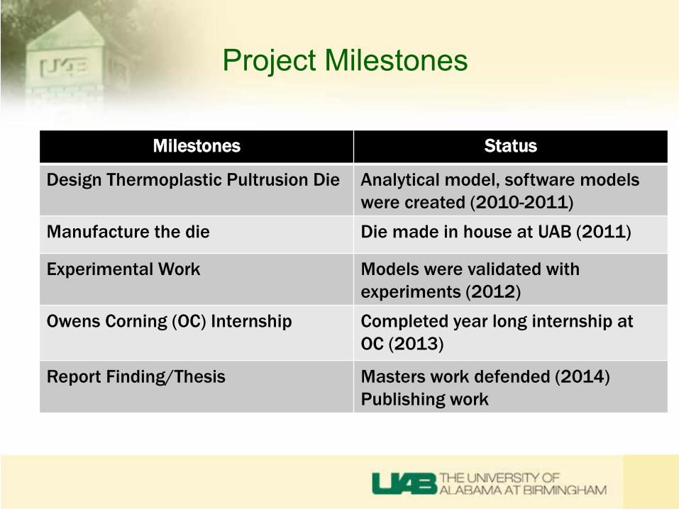
Project Milestones
Milestones Status
Design Thermoplastic Pultrusion Die Analytical model, software models were created (2010-2011)
Manufacture the die Die made in house at UAB (2011)
Experimental Work Models were validated with experiments (2012)
Owens Corning (OC) Internship Completed year long internship at OC (2013)
Report Finding/Thesis Masters work defended (2014) Publishing work

Project Approach and Accomplishments
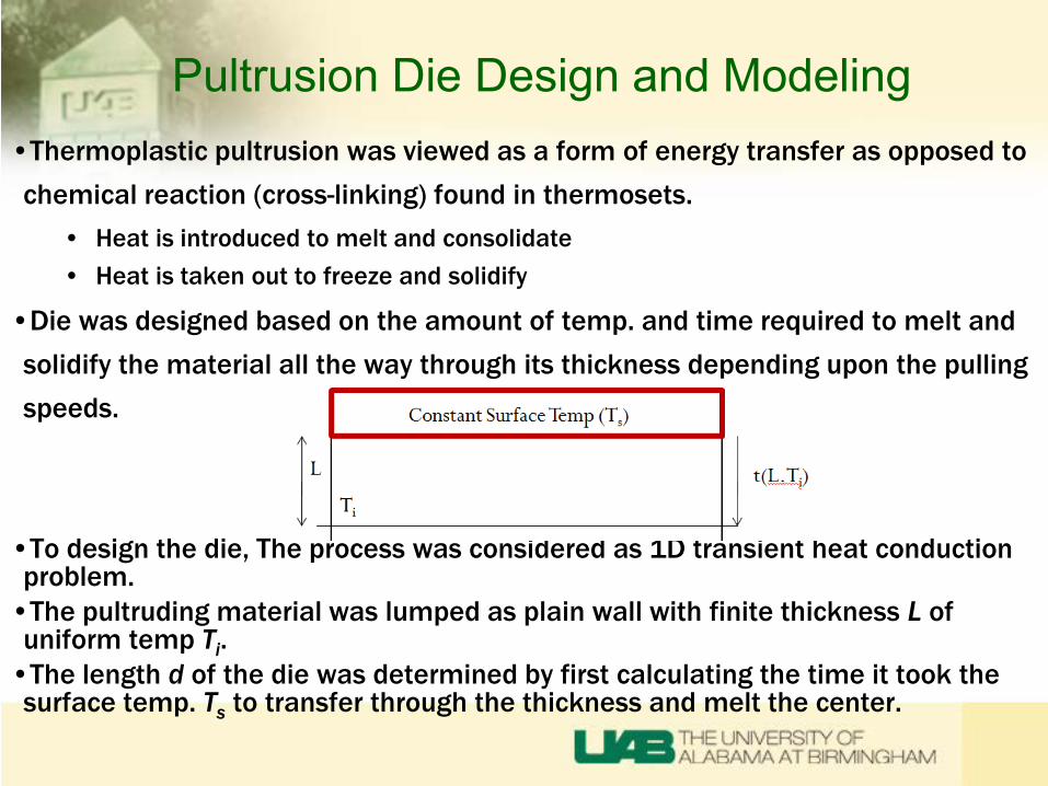
Pultrusion Die Design and Modeling •Thermoplastic pultrusion was viewed as a form of energy transfer as opposed to chemical reaction (cross-linking) found in thermosets.
• Heat is introduced to melt and consolidate • Heat is taken out to freeze and solidify
•Die was designed based on the amount of temp. and time required to melt and solidify the material all the way through its thickness depending upon the pulling speeds.
•To design the die, The process was considered as 1D transient heat conduction problem. •The pultruding material was lumped as plain wall with finite thickness L of uniform temp Ti. •The length d of the die was determined by first calculating the time it took the surface temp. Ts to transfer through the thickness and melt the center.
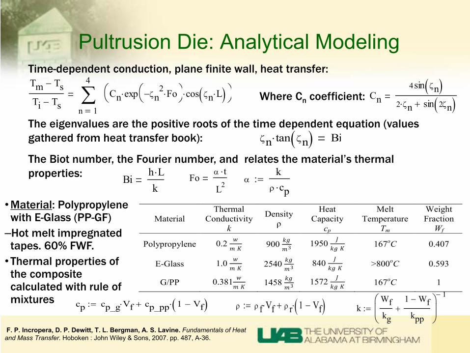
Pultrusion Die: Analytical Modeling Time-dependent conduction, plane finite wall, heat transfer: Tm Ts−
Ti Ts−1
4
n
Cn exp ζn2− Fo⋅
⋅ cos ζn L⋅( )⋅
∑
=Cn
4sin ζn( )2 ζn⋅ sin 2ζn( )+
ζn tan ζn( )⋅ Bi
Bih L⋅k
Foα t⋅
L2α
kρ cp⋅
:=
Where Cn coefficient:
The eigenvalues are the positive roots of the time dependent equation (values gathered from heat transfer book):
The Biot number, the Fourier number, and relates the material’s thermal properties:
F. P. Incropera, D. P. Dewitt, T. L. Bergman, A. S. Lavine. Fundamentals of Heat and Mass Transfer. Hoboken : John Wiley & Sons, 2007. pp. 487, A-36.
•Material: Polypropylene with E-Glass (PP-GF)
–Hot melt impregnated tapes. 60% FWF. •Thermal properties of the composite calculated with rule of mixtures
Material Thermal
Conductivity k
Density ρ
Heat Capacity
cp
Melt Temperature
Tm
Weight Fraction
Wf
Polypropylene 0.2 𝑤𝑤𝑚𝑚 𝐾𝐾
900 𝑘𝑘𝑘𝑘𝑚𝑚3 1950 𝐽𝐽
𝑘𝑘𝑘𝑘 𝐾𝐾 167oC 0.407
E-Glass 1.0 𝑤𝑤𝑚𝑚 𝐾𝐾
2540 𝑘𝑘𝑘𝑘𝑚𝑚3 840 𝐽𝐽
𝑘𝑘𝑘𝑘 𝐾𝐾 >800oC 0.593
G/PP 0.381 𝑤𝑤𝑚𝑚 𝐾𝐾
1458 𝑘𝑘𝑘𝑘𝑚𝑚3 1572 𝐽𝐽
𝑘𝑘𝑘𝑘 𝐾𝐾 167oC 1
k
Wfkg
1 Wf−
kpp+
1−
:=ρ ρ f Vf⋅ ρ r 1 Vf−( )⋅+:=cp cp_g Vf⋅ cp_pp 1 Vf−( )⋅+:=
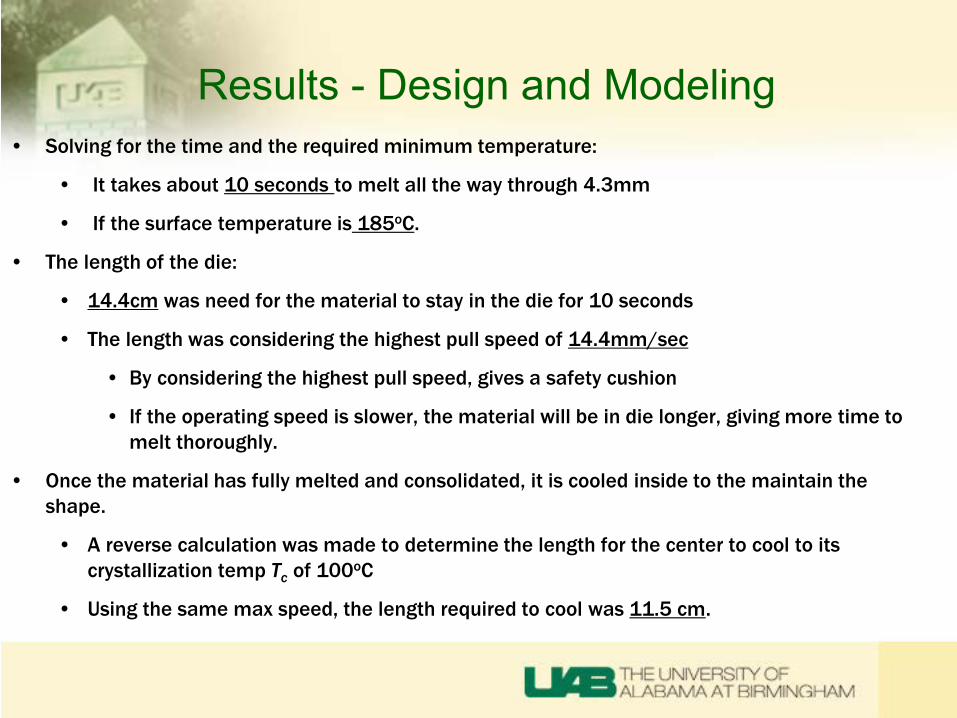
Results - Design and Modeling • Solving for the time and the required minimum temperature:
• It takes about 10 seconds to melt all the way through 4.3mm
• If the surface temperature is 185oC.
• The length of the die:
• 14.4cm was need for the material to stay in the die for 10 seconds
• The length was considering the highest pull speed of 14.4mm/sec
• By considering the highest pull speed, gives a safety cushion
• If the operating speed is slower, the material will be in die longer, giving more time to melt thoroughly.
• Once the material has fully melted and consolidated, it is cooled inside to the maintain the shape.
• A reverse calculation was made to determine the length for the center to cool to its crystallization temp Tc of 100oC
• Using the same max speed, the length required to cool was 11.5 cm.
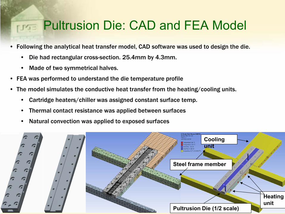
Pultrusion Die: CAD and FEA Model • Following the analytical heat transfer model, CAD software was used to design the die.
• Die had rectangular cross-section. 25.4mm by 4.3mm.
• Made of two symmetrical halves.
• FEA was performed to understand the die temperature profile
• The model simulates the conductive heat transfer from the heating/cooling units.
• Cartridge heaters/chiller was assigned constant surface temp.
• Thermal contact resistance was applied between surfaces
• Natural convection was applied to exposed surfaces
Steel frame member
Heating unit
Cooling unit
Pultrusion Die (1/2 scale)
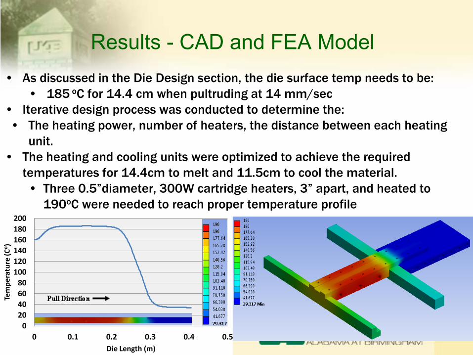
Results - CAD and FEA Model • As discussed in the Die Design section, the die surface temp needs to be:
• 185 oC for 14.4 cm when pultruding at 14 mm/sec • Iterative design process was conducted to determine the: • The heating power, number of heaters, the distance between each heating
unit. • The heating and cooling units were optimized to achieve the required
temperatures for 14.4cm to melt and 11.5cm to cool the material. • Three 0.5”diameter, 300W cartridge heaters, 3” apart, and heated to
190oC were needed to reach proper temperature profile
020406080
100120140160180200
0 0.1 0.2 0.3 0.4 0.5
Tem
pera
ture
(Co )
Die Length (m)
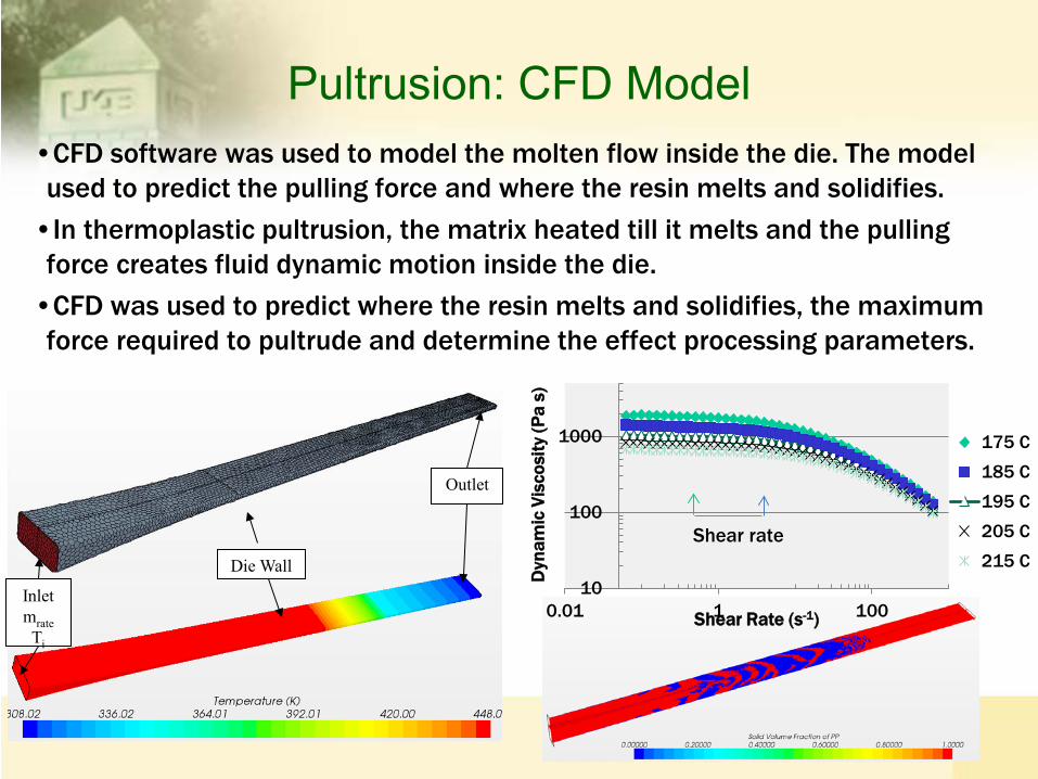
Pultrusion: CFD Model •CFD software was used to model the molten flow inside the die. The model used to predict the pulling force and where the resin melts and solidifies. •In thermoplastic pultrusion, the matrix heated till it melts and the pulling force creates fluid dynamic motion inside the die. •CFD was used to predict where the resin melts and solidifies, the maximum force required to pultrude and determine the effect processing parameters.
Inlet mrate Ti
Die Wall
Outlet
10
100
1000
0.01 1 100
Dyn
amic
Vis
cosi
ty (P
a s)
Shear Rate (s-1)
175 C
185 C
195 C
205 C
215 CShear rate
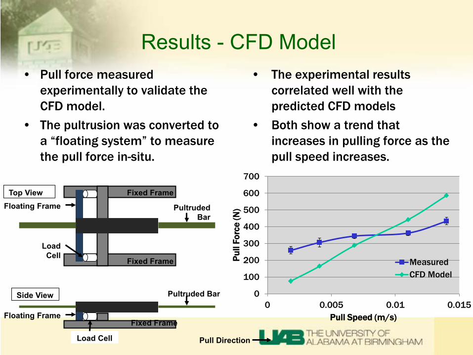
Results - CFD Model • The experimental results
correlated well with the predicted CFD models
• Both show a trend that increases in pulling force as the pull speed increases.
• Pull force measured experimentally to validate the CFD model.
• The pultrusion was converted to a “floating system” to measure the pull force in-situ.
0
100
200
300
400
500
600
700
0 0.005 0.01 0.015
Pull
Forc
e (N
)
Pull Speed (m/s)
MeasuredCFD Model
Load Cell
Fixed Frame
Fixed Frame
Floating Frame Pultruded Bar
Top View
Side View
Fixed Frame
Load Cell
Floating Frame
Pultruded Bar
Pull Direction

Collaborative Work with Partners
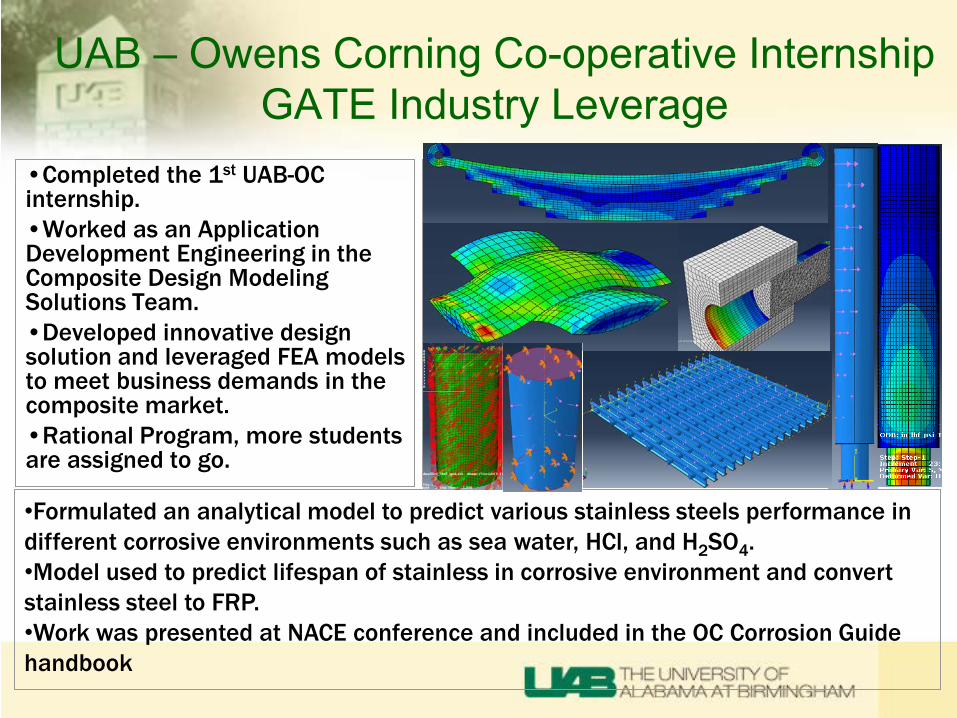
UAB – Owens Corning Co-operative Internship GATE Industry Leverage
•Completed the 1st UAB-OC internship. •Worked as an Application Development Engineering in the Composite Design Modeling Solutions Team. •Developed innovative design solution and leveraged FEA models to meet business demands in the composite market. •Rational Program, more students are assigned to go.
•Formulated an analytical model to predict various stainless steels performance in different corrosive environments such as sea water, HCl, and H2SO4. •Model used to predict lifespan of stainless in corrosive environment and convert stainless steel to FRP. •Work was presented at NACE conference and included in the OC Corrosion Guide handbook
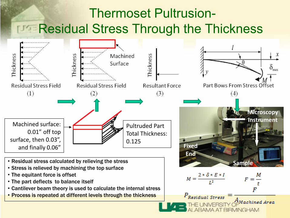
Thermoset Pultrusion- Residual Stress Through the Thickness
Sample
Microscopy Instrument
Fixed End
Machined surface: 0.01” off top
surface, then 0.03”, and finally 0.06”
Pultruded Part Total Thickness: 0.125
• Residual stress calculated by relieving the stress • Stress is relieved by machining the top surface • The equitant force is offset • The part deflects to balance itself • Cantilever beam theory is used to calculate the internal stress • Process is repeated at different levels through the thickness
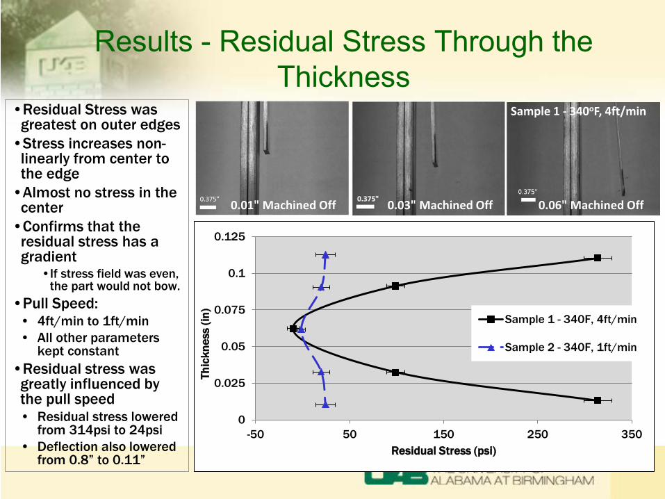
Results - Residual Stress Through the Thickness
•Residual Stress was greatest on outer edges •Stress increases non-
linearly from center to the edge •Almost no stress in the
center •Confirms that the
residual stress has a gradient
•If stress field was even, the part would not bow.
•Pull Speed: • 4ft/min to 1ft/min • All other parameters
kept constant •Residual stress was
greatly influenced by the pull speed • Residual stress lowered
from 314psi to 24psi • Deflection also lowered
from 0.8” to 0.11”
Sample 1 - 340oF, 4ft/min
0.03" Machined Off 0.06" Machined Off 0.01" Machined Off
0
0.025
0.05
0.075
0.1
0.125
-50 50 150 250 350
Thic
knes
s (in
)
Residual Stress (psi)
Sample 1 - 340F, 4ft/min
Sample 2 - 340F, 1ft/min
Summary
Through the GATE funding: • Developed multiple models pultrusion die for thermoplastics • Established a baseline for thermoplastic pultrusion design criteria
• Could be used for any fiber/matrix combination including carbon fiber. • Developed a method to measure residual stress in pultruded
composites • Completed 1 year industry experience with UAB-OC Co-op internship • Received sound understanding and hands on experience in many
composite process techniques and ASTM testing methods • Pultrusion, VARTM, extrusion, compression molding, and injection
molding. • Trained on multiple CAD/FEA modeling softwares
• Pro/E, Abaqus, Ansys WB, Star-CCM+, HyperMesh, MoldFlow® and MathCAD.
Publications • Thermoplastic Pultrusion Modeling and Experimental Studies, Khongor
Jamiyanaa, University of Alabama at Birmingham. 2012 SPE ACCE Student Poster
• Modeling and Experimental Studies on Thermoplastic Composite Pultrusion, Jamiyanaa, Khongor. Vaidya, Uday. University of Alabama at Birmingham. ACMA 2013 Technical paper, pultrusion track.
• Performance Comparison of Stainless-Steel and E-CR Based FRP Composite in Corrosive Environment. Vaiyda, Amol., Spoo, Kevin., Jamiyanaa, Khongor. Owens Corning, University of Alabama at Birmingham. NACE International Conference.
• What Causes Bow in Pultrusion. Jamiyanaa, Khongor. University of Alabama at Birmingham. Alabama Composites Conference, 2013. Student Poster.
• Development of Residual Stress in Pultruded Composites. Jamiyanaa, Khongor., Spoo, Kevin. University of Alabama at Birmingham, Owens Corning. 2014 ACMA CAMX Conference. Pultrusion Track. (Up-coming)