development of testing method for adhesion strength ...15th+japan+us+w… · development of testing...
TRANSCRIPT
superior performance.powerful technology.
SuperPower Inc. is a subsidiary of Royal Philips Electronics N.V.
Development of Testing Method for Adhesion Strength Characterization of 2G HTS WiresYifei Zhang1, J.M. Duval1, A.R. Knoll1, D.W. Hazelton1, P. Brownsey1, S. Repnoy1, S. Soloveichik1, A. Sundaram1, R.B. McClure1, G. Majkic2, and V. Selvamanickam1, 2
The 15th Japan – US Workshop on Advanced Superconductors Osaka, Japan October 27 - 29, 2011
1 SuperPower Inc., Schenectady, NY 12304 U.S.A.2 University of Houston, Houston, TX 77204 U.S.A.

21A515th Japan-US Workshop on Advanced Superconductors Osaka, Japan October 27 - 29, 2011
Outline
• Introduction• Mechanical properties of 2G HTS wire• Coil degradation and wire delamination• Transverse tensile strength testing• Peel test – method & evaluation• Peeling angle and weakest interface• Improvement of adhesion strength (peel strength)• Summary
31A515th Japan-US Workshop on Advanced Superconductors Osaka, Japan October 27 - 29, 2011
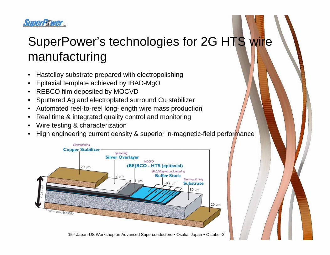
• Hastelloy substrate prepared with electropolishing• Epitaxial template achieved by IBAD-MgO• REBCO film deposited by MOCVD• Sputtered Ag and electroplated surround Cu stabilizer• Automated reel-to-reel long-length wire mass production• Real time & integrated quality control and monitoring• Wire testing & characterization• High engineering current density & superior in-magnetic-field performance
SuperPower’s technologies for 2G HTS wire manufacturing
41A515th Japan-US Workshop on Advanced Superconductors Osaka, Japan October 27 - 29, 2011
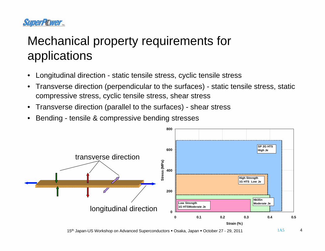
longitudinal direction
transverse direction
0
200
400
600
800
0 0.1 0.2 0.3 0.4 0.5
Strain (%)
Stre
ss (M
Pa)
SP 2G HTSHigh Je
High Strength 1G HTS Low Je
Nb3Sn Moderate JeLow Strength
1G HTSModerate Je
Mechanical property requirements for applications• Longitudinal direction - static tensile stress, cyclic tensile stress• Transverse direction (perpendicular to the surfaces) - static tensile stress, static
compressive stress, cyclic tensile stress, shear stress • Transverse direction (parallel to the surfaces) - shear stress• Bending - tensile & compressive bending stresses

51A515th Japan-US Workshop on Advanced Superconductors Osaka, Japan October 27 - 29, 2011
Coil performance, wire delamination and adhesion strength • Coil Ic drops through
thermal cycling between RT and 77K;
• Degradation occurs only to epoxy wound or impregnated coils;
• Believed to be due to transverse tensile stress originated from difference in coefficients of thermal expansion.
I-V curves of dry- & wet-wound coils
61A515th Japan-US Workshop on Advanced Superconductors Osaka, Japan October 27 - 29, 2011
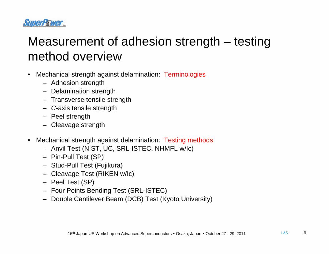
Measurement of adhesion strength – testing method overview• Mechanical strength against delamination: Terminologies
– Adhesion strength– Delamination strength– Transverse tensile strength– C-axis tensile strength– Peel strength– Cleavage strength
• Mechanical strength against delamination: Testing methods– Anvil Test (NIST, UC, SRL-ISTEC, NHMFL w/Ic)– Pin-Pull Test (SP)– Stud-Pull Test (Fujikura) – Cleavage Test (RIKEN w/Ic)– Peel Test (SP)– Four Points Bending Test (SRL-ISTEC)– Double Cantilever Beam (DCB) Test (Kyoto University)
71A515th Japan-US Workshop on Advanced Superconductors Osaka, Japan October 27 - 29, 2011
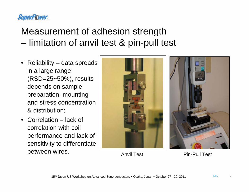
Anvil Test
Anvils
Pin-Pull Test
Measurement of adhesion strength– limitation of anvil test & pin-pull test
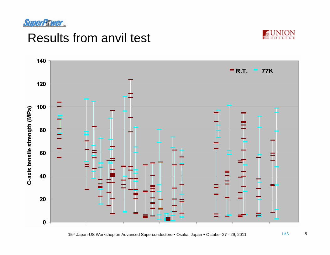
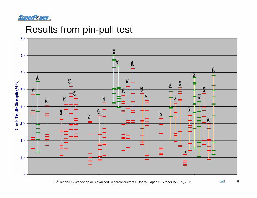
• Reliability – data spreads in a large range (RSD=25~50%), results depends on sample preparation, mounting and stress concentration & distribution;
• Correlation – lack of correlation with coil performance and lack of sensitivity to differentiate between wires.
81A515th Japan-US Workshop on Advanced Superconductors Osaka, Japan October 27 - 29, 2011
Results from anvil test
91A515th Japan-US Workshop on Advanced Superconductors Osaka, Japan October 27 - 29, 2011
Results from pin-pull test

101A515th Japan-US Workshop on Advanced Superconductors Osaka, Japan October 27 - 29, 2011
Sources of uncertainty for pin-pull test
Effective Solder Joint Area
Stress concentration & distribution
Tape/Pin Alignment
Tape Uniformity (along length)
Tape Uniformity (across width)
Edge Effect
Load/Pin Alignment
Loading Speed
Wire TestingFabrication
* Strength defined as (peak load)/(nominal solder joint area) based on the solder-pin pull test** Data obtained from a group of around 10 samples fabricated with a same wire
C-axis Tensile Strength* Data** Uncertainty
Tape/G10-Plate Alignment
111A515th Japan-US Workshop on Advanced Superconductors Osaka, Japan October 27 - 29, 2011
Measurement of adhesion strength– requirements on testing method• Quantification – well defined quantitative values for evaluation and comparison;• Reliability – reproducible data with minimized effects from sample preparation,
fixture alignment, mounting and handling (operator);• Sensitivity – accurate enough to differentiate between wires with small
difference in the strength;• Relevance – results closely correlate with coil performance (wire under a stress
state similar to that in a coil, at least in the transverse direction).
121A515th Japan-US Workshop on Advanced Superconductors Osaka, Japan October 27 - 29, 2011
Angular Jigs
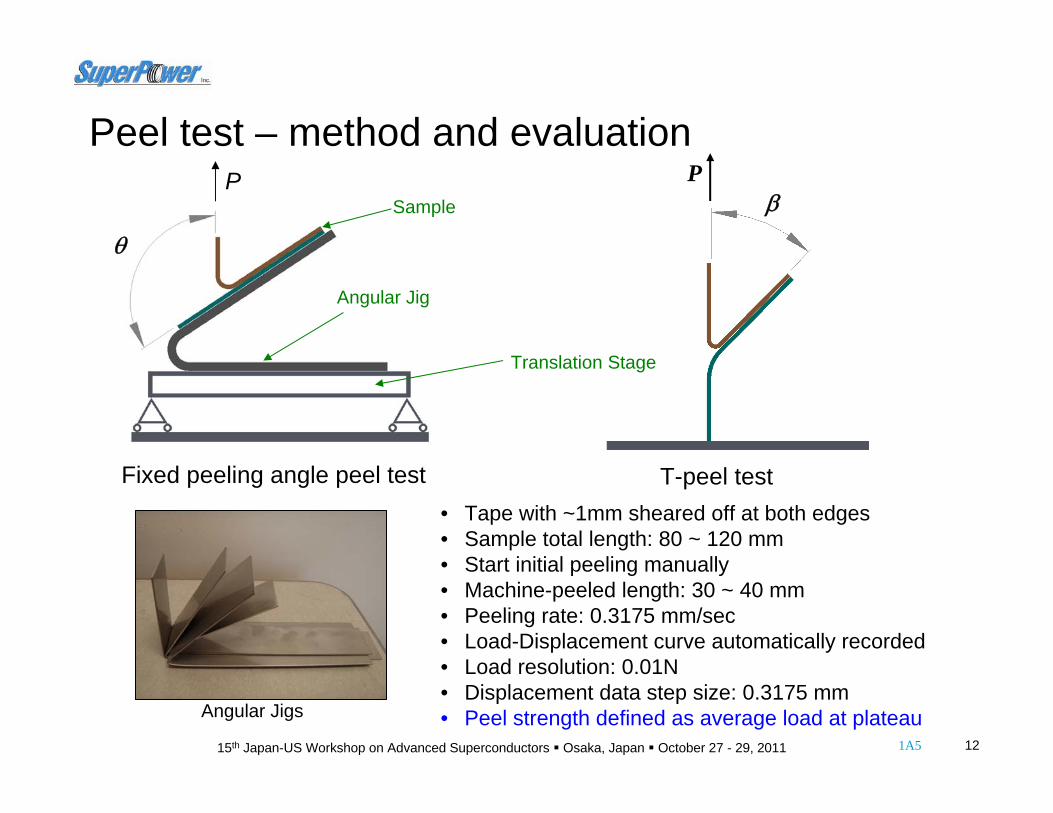
• Tape with ~1mm sheared off at both edges• Sample total length: 80 ~ 120 mm• Start initial peeling manually• Machine-peeled length: 30 ~ 40 mm • Peeling rate: 0.3175 mm/sec• Load-Displacement curve automatically recorded• Load resolution: 0.01N• Displacement data step size: 0.3175 mm• Peel strength defined as average load at plateau
Pβ
θ
Translation Stage
Angular Jig
SampleP
T-peel test
Peel test – method and evaluation
Fixed peeling angle peel test
131A515th Japan-US Workshop on Advanced Superconductors Osaka, Japan October 27 - 29, 2011
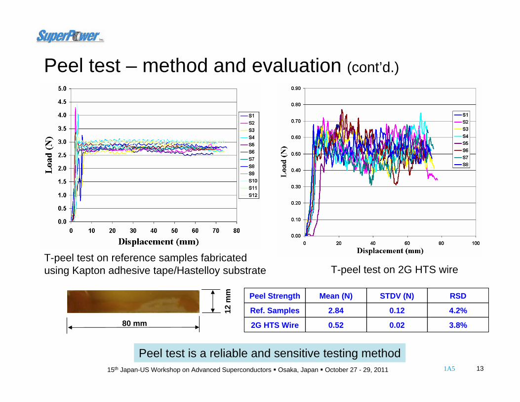
T-peel test on reference samples fabricated using Kapton adhesive tape/Hastelloy substrate T-peel test on 2G HTS wire
80 mm
12 m
m
3.8%0.020.522G HTS Wire
4.2%0.122.84Ref. Samples
RSDSTDV (N)Mean (N)Peel Strength
Peel test is a reliable and sensitive testing method
Peel test – method and evaluation (cont’d.)

141A515th Japan-US Workshop on Advanced Superconductors Osaka, Japan October 27 - 29, 2011
180° peel test
90° peel testOptical microscopic images of bottom peeled surfaces.
(a)
(b)
Peel test - effects of peeling angles
Stress state at peeling front depends on peeling angle
Load versus displacement curves for 2G HTS wire

151A515th Japan-US Workshop on Advanced Superconductors Osaka, Japan October 27 - 29, 2011
SEM images of bottom peeled surfaces from (a) 180°; (b) 90° test
(a)
(b)
Peel strength & weakest interface dependent on peeling angle (loading scheme or stress state)
Peel test - identification of weakest interface
EDS spectra on bottom peeled surfaces from 180° test and 90° test.
Cu
Gd
Mg
AlY
Mo
BaCr
MnGd
Ba
Ba
161A515th Japan-US Workshop on Advanced Superconductors Osaka, Japan October 27 - 29, 2011
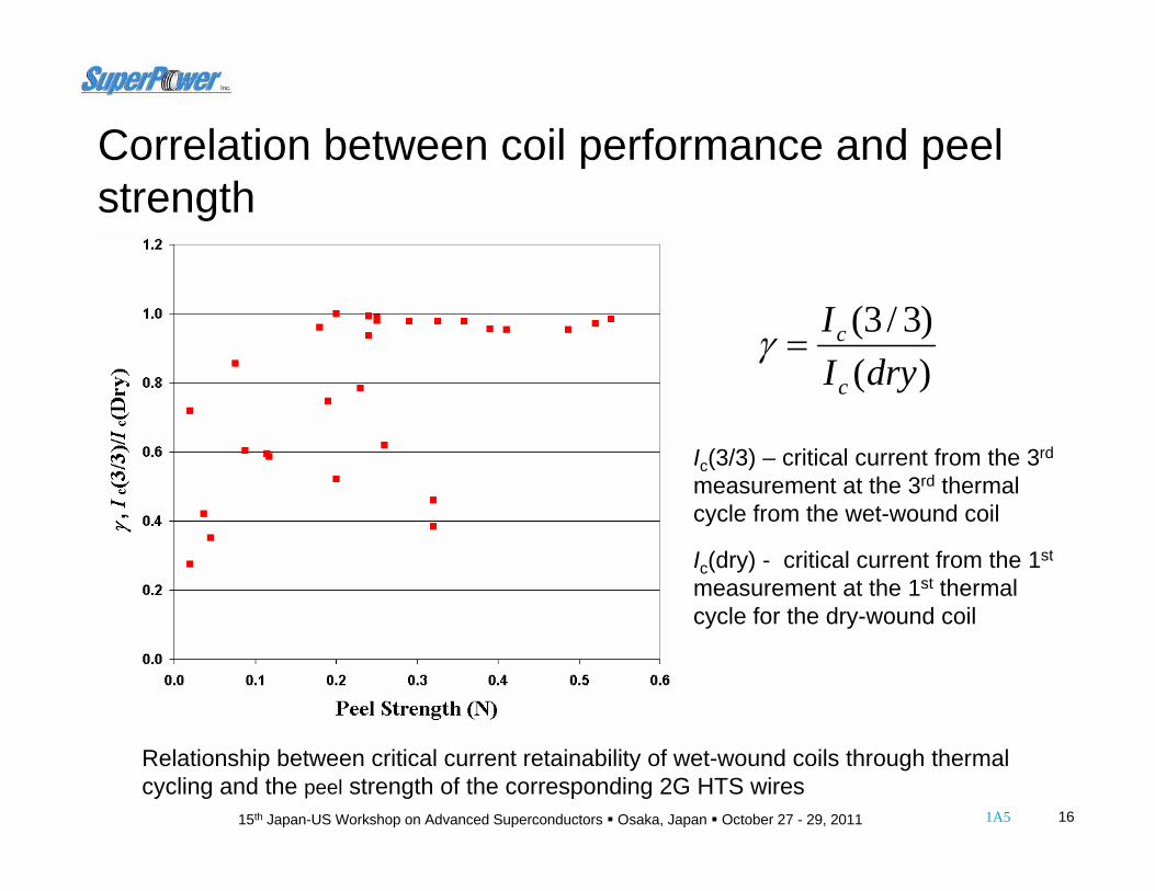
Relationship between critical current retainability of wet-wound coils through thermal cycling and the peel strength of the corresponding 2G HTS wires
)()3/3(
dryII
c
c=γ
Ic(3/3) – critical current from the 3rd
measurement at the 3rd thermal cycle from the wet-wound coil
Ic(dry) - critical current from the 1st
measurement at the 1st thermal cycle for the dry-wound coil
Correlation between coil performance and peel strength

171A515th Japan-US Workshop on Advanced Superconductors Osaka, Japan October 27 - 29, 2011
P = η + ψ
P – peel strength;η – interfacial bonding strength, (interfacial fracture energy);ψ – mechanical energy dissipated due to material plastic deformation during peeling.
Adhesion strength (peel strength) can be improved by reinforcing the interfacial strength and tuning the mechanical properties of the over layers.
Improvement of adhesion strength (peel strength)
181A515th Japan-US Workshop on Advanced Superconductors Osaka, Japan October 27 - 29, 2011
Conclusions
1. Transverse tensile strength (c-axis strength, adhesion strength, peel strength) is an important mechanical property, critical to thermal stability of wet-wound and impregnated coils;
2. Peel test is a reliable testing method for studying adhesion strength of 2G HTS wires, with good reproducibility and sensitivity in data;
3. Peel strength and weakest interface (peeling location) are dependent on peeling angle (stress state at peeling front, loading scheme);
4. Correlation was found between wet-wound coil performance and peel strength;
5. Adhesion strength (peel strength) can be improved by reinforcinginterfacial bonding strength and tuning the mechanical properties of the over layers.