development of inherently safe technologies for bwrs · development of inherently safe technologies...
TRANSCRIPT
© Hitachi, Ltd. 2015. All rights reserved.
Development of Inherently Safe Technologies for BWRs
Hitachi Ltd., Hitachi Research Laboratory
Feb. 17, 2015
Kazuaki Kitou, Naoyuki Ishida, Akinori Tamura, Ryou Ishibashi, Masaki Kanada and Mamoru Kamoshida
IEM-8 IAEA-CN-235-10
Feb. 16-20, 2015, Vienna, Austria
© Hitachi, Ltd. 2015. All rights reserved.
1. Background and objective
2. Overview of the development items
3. Conclusions
Contents
1
© Hitachi, Ltd. 2015. All rights reserved.
1. Background and objective
2
© Hitachi, Ltd. 2015. All rights reserved.
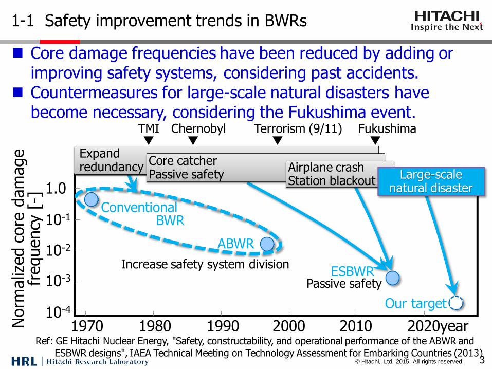
1-1 Safety improvement trends in BWRs
3
Core damage frequencies have been reduced by adding or improving safety systems, considering past accidents.
Countermeasures for large-scale natural disasters have become necessary, considering the Fukushima event.
Ref: GE Hitachi Nuclear Energy, "Safety, constructability, and operational performance of the ABWR and
ESBWR designs", IAEA Technical Meeting on Technology Assessment for Embarking Countries (2013)
10-4
10-3
10-2
10-1
1.0
1970 1980 1990 2000 2010 2020year
ABWR
ConventionalBWR
Our target
ESBWRIncrease safety system division
Passive safety
Norm
aliz
ed c
ore
dam
age
frequency
[-]
Expand redundancy
Core catcherPassive safety
TMI▼
Fukushima▼
Chernobyl▼
Terrorism (9/11)▼
Airplane crashStation blackout
Large-scalenatural disaster

© Hitachi, Ltd. 2015. All rights reserved.
1-2 Fukushima event sequence and development needs
4
Tsunami & station blackout (SBO)
Cooling system stop
Hydrogen explosion
Core melt
Primary containment vessel failure
Development needs were selected considering the Fukushima event sequence.
Recognition of accurate plant status
Long-term cooling system without electricity
Prevention of hydrogen explosion
Sequence Needs
© Hitachi, Ltd. 2015. All rights reserved.
1-3 Objective and development items in the study
5
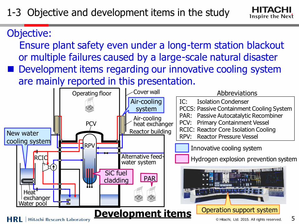
Objective: Ensure plant safety even under a long-term station blackout
or multiple failures caused by a large-scale natural disaster Development items regarding our innovative cooling system
are mainly reported in this presentation.
Innovative cooling system
Hydrogen explosion prevention system
IC: Isolation Condenser PCCS: Passive Containment Cooling System PAR: Passive Autocatalytic Recombiner PCV: Primary Containment Vessel RCIC: Reactor Core Isolation Cooling RPV: Reactor Pressure Vessel
Abbreviations
Operation support system
RCIC
IC
Air-cooling heat exchanger
PCCS
Reactor building
PCV
RPV Alternative feed-water system
Cover wall Operating floor
SiC fuel cladding
Air-cooling system
PAR
water-cooling systems
Development items
RCIC
Air-cooling heat exchanger
Reactor building
PCV
Heat exchanger
Water pool
RPV
Alternative feed-water system
Cover wall Operating floor
SiC fuel cladding
New water cooling system
Air-cooling system
PAR
© Hitachi, Ltd. 2015. All rights reserved.
Heat exchanger
1-4 New passive water-cooling system
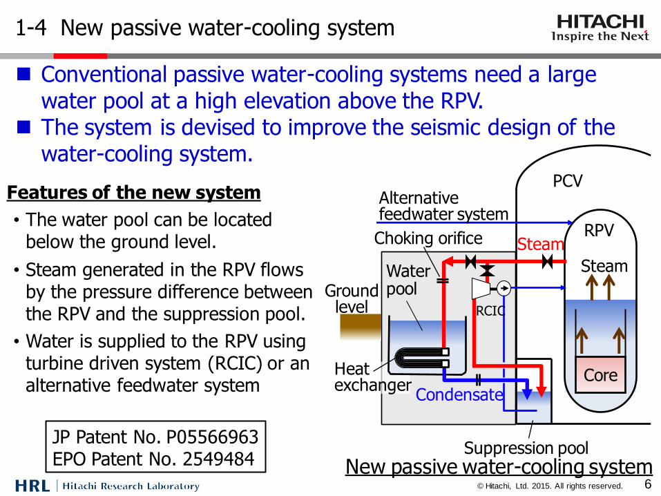
Conventional passive water-cooling systems need a large water pool at a high elevation above the RPV.
The system is devised to improve the seismic design of the water-cooling system.
New passive water-cooling system
Features of the new system
• The water pool can be located below the ground level.
• Steam generated in the RPV flows by the pressure difference between the RPV and the suppression pool.
• Water is supplied to the RPV using turbine driven system (RCIC) or an alternative feedwater system
Steam
RPV
Core
Steam
PCV
Ground level
Condensate
Suppression pool
Choking orifice
RCIC
Water pool
6
Alternative feedwater system
JP Patent No. P05566963 EPO Patent No. 2549484
© Hitachi, Ltd. 2015. All rights reserved.
2. Overview of the development items
7

© Hitachi, Ltd. 2015. All rights reserved.
2-1 Innovative cooling system
8
Elapsed time [day]
0
10
40
5 10 15 0
Air-cooling system
Water-cooling system
20
30
Activation period of both systems
The decay heat for an initial 10 days is removed by both the water- and the air-cooling systems; then it is removed by only the air-cooling system.
We have been developing both the water- and the air-cooling systems to realize the innovative cooling system.
Deca
y heat [M
W]
Capacity of the water pool can be reduced significantly using the air-cooling system.
Infinite-time cooling can be achieved.
(4700M
Wt c
lass
react
or)
RCIC
Air-cooling heat exchanger
Reactor building
PCV
Heat exchanger
Water pool
RPV
Alternative feed-water system
Cover wall Operating floor
New water cooling system
Air-cooling system
© Hitachi, Ltd. 2015. All rights reserved.
0
10
20
30
40
50
60
0.0 0.5 1.0 1.5 2.0 2.5 3.0 3.5 4.0 4.5
Operation range for the new system
1.0 2.0 3.0 7.0
PCCS
IC
0
60
50
40
30
20
10
Inle
t ste
am
velo
city
[m/s
]
Pressure [MPa]0
◆: 27.2 mm O.D.
□: 42.7 mm O.D.
EquivalentRe number
9
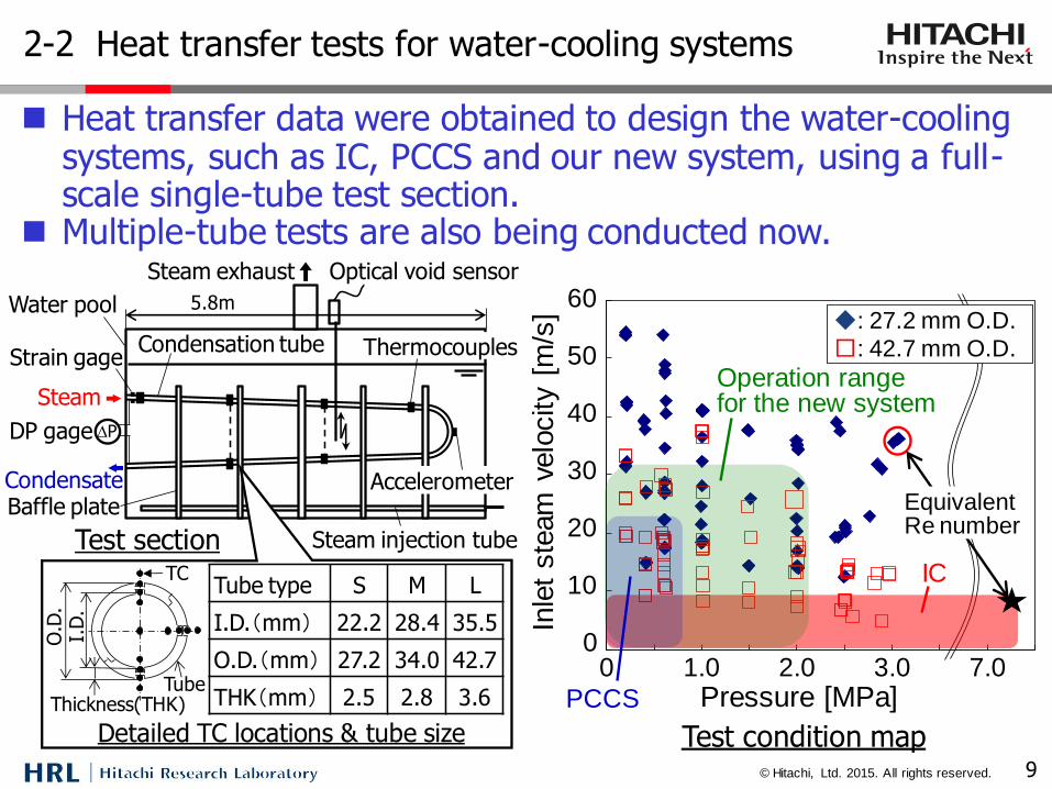
Heat transfer data were obtained to design the water-cooling systems, such as IC, PCCS and our new system, using a full-scale single-tube test section.
Multiple-tube tests are also being conducted now.
2-2 Heat transfer tests for water-cooling systems
Test condition map
Steam exhaust
Strain gageCondensation tube
Optical void sensor
Accelerometer
Thermocouples
Water pool
Steam injection tube
Baffle plate
Steam
5.8m
Condensate
DP gage DP
Test section
Tube type S M L
I.D.(mm) 22.2 28.4 35.5
O.D.(mm) 27.2 34.0 42.7
THK(mm) 2.5 2.8 3.6
Detailed TC locations & tube size
Tube
I.D
.O
.D.
Thickness(THK)
TC

© Hitachi, Ltd. 2015. All rights reserved.
0
2
4
6
8
10
12
14
0 2 4 6 8 10 12 14
◆:27.2 mm O.D.■:42.7 mm O.D.
+20%
-20%
10
8
6
4
2
0
12
Boili
ng h
eat tr
ansf
er
coeff
icie
nt
(Experim
ent)
[kW
/(m
2・K
)]
0 2 4 6 8 10 12
14
14Boiling heat transfer coefficient
(Calculation) [kW/(m2・K)]
5.0
674.066.1
bsoso
d
Dqh
5.02146.0 GLb gd
0
100
200
300
400
500
600
700
800
0.0 0.5 1.0 1.5 2.0 2.5 3.0 3.50.0 0.5 1.0 1.5 2.0 2.5 3.0 3.50
100
200
300
400
500
600
700
8009.3m
7.7m
4.9m
3.3m
27.2mm O.D.
Pressure [MPa]
Ste
am
mass
flo
w r
ate
[kg/h
]
Analysis results
Experimental results
10
The completed condensation length map has been made based on test results[1].
Modified heat transfer correlations have been developed [2].
2-3 Test results for water-cooling systems
Completed condensation length map[1]
TC1 0.1m
TC2 1.7m
TC3 3.3m
TC4 4.9m
TC5 7.7m
TC6 9.3m
The mark means condensation completed between TC3 and TC4.
Developed heat transfer correlation[2]
[1] N. Ishida et al., ICONE22-31007 (2014) [2] H. Hosoi et al., NUTHOS10-1191 (2014)
© Hitachi, Ltd. 2015. All rights reserved.
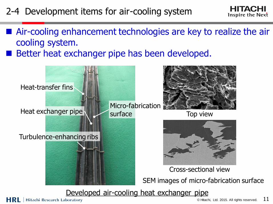
2-4 Development items for air-cooling system
11
Air-cooling enhancement technologies are key to realize the air cooling system.
Better heat exchanger pipe has been developed.
Reactor building
PCV
RPV
Cover wall Operating floor
Air-cooling system
Air-cooling heat exchanger
Heat exchanger pipe
Heat-transfer fins
Turbulence-enhancing ribs
Micro-fabrication surface
Developed air-cooling heat exchanger pipe
Heat exchanger pipe
Heat-transfer fins
Turbulence-enhancing ribs
Micro-fabrication surface Top view
Cross-sectional view
Developed air-cooling heat exchanger pipe
SEM images of micro-fabrication surface
© Hitachi, Ltd. 2015. All rights reserved.
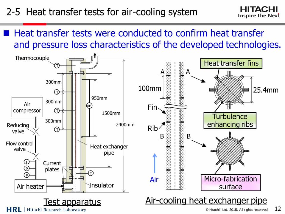
2-5 Heat transfer tests for air-cooling system
12
Heat transfer tests were conducted to confirm heat transfer and pressure loss characteristics of the developed technologies.
Test apparatus Air-cooling heat exchanger pipe
T
T
F
2400mm
ΔP
950mm
1500mm
T
T
T
300mm
300mm
300mm
P
T
Thermocouple
Air compressor
Reducing valve
Flow control valve
Air heater
Current plates
Insulator
Heat exchanger pipe
A A
B B
100mm 25.4mm
Air
Heat transfer fins
Turbulence enhancing ribs
Micro-fabrication surface
Fin
Rib
© Hitachi, Ltd. 2015. All rights reserved.
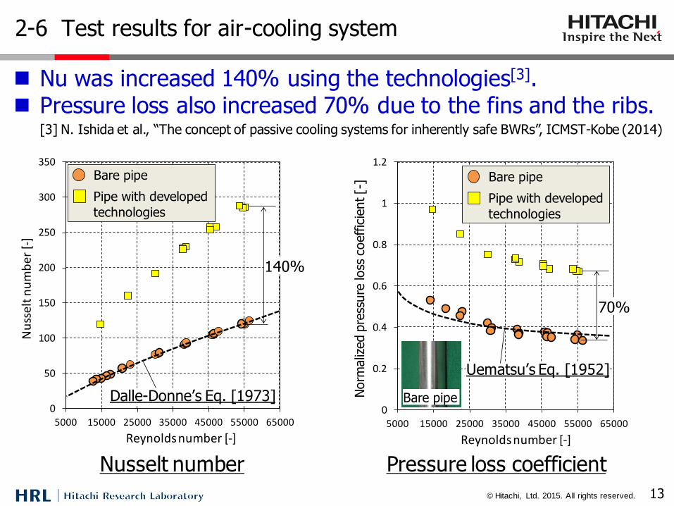
2-6 Test results for air-cooling system
13
Nu was increased 140% using the technologies[3]. Pressure loss also increased 70% due to the fins and the ribs.
Nusselt number Pressure loss coefficient
[3] N. Ishida et al., “The concept of passive cooling systems for inherently safe BWRs”, ICMST-Kobe (2014)
0
50
100
150
200
250
300
350
5000 15000 25000 35000 45000 55000 65000
Nu
ssel
t n
um
ber
[-]
Reynolds number [-]
Pipe with developed
technologies
Bare pipe
140%
Dalle-Donne’s Eq. [1973]0
0.2
0.4
0.6
0.8
1
1.2
5000 15000 25000 35000 45000 55000 65000
Pre
ssu
re-l
oss
co
effi
cien
t[-
]
Reynolds number [-]
Pipe with developed
technologies
Bare pipe
70%
Uematsu’s Eq. [1952]N
orm
aliz
ed p
ress
ure
loss
coeffic
ient [-
]
Bare pipe
© Hitachi, Ltd. 2015. All rights reserved.
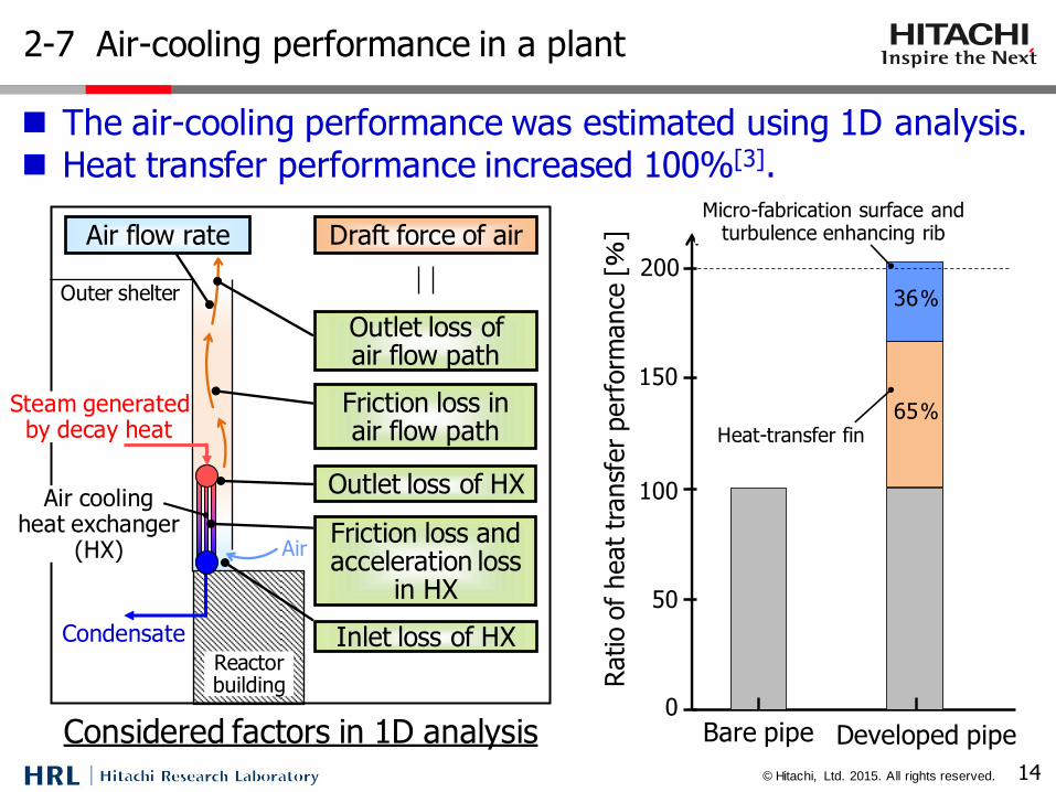
2-7 Air-cooling performance in a plant
14
The air-cooling performance was estimated using 1D analysis. Heat transfer performance increased 100%[3].
Reactor building
Outer shelter
Air
Air cooling heat exchanger
(HX)
Considered factors in 1D analysis
Inlet loss of HX
Friction loss and acceleration loss
in HX
Outlet loss of HX
Friction loss in air flow path
Outlet loss of air flow path
Draft force of air Air flow rate
Steam generated by decay heat
Condensate
0
50
100
150
200
Ratio o
f heat
transf
er
perf
orm
ance
[%]
Bare pipe Developed pipe
Heat-transfer fin
Micro-fabrication surface and turbulence enhancing rib
65%
36%
© Hitachi, Ltd. 2015. All rights reserved.
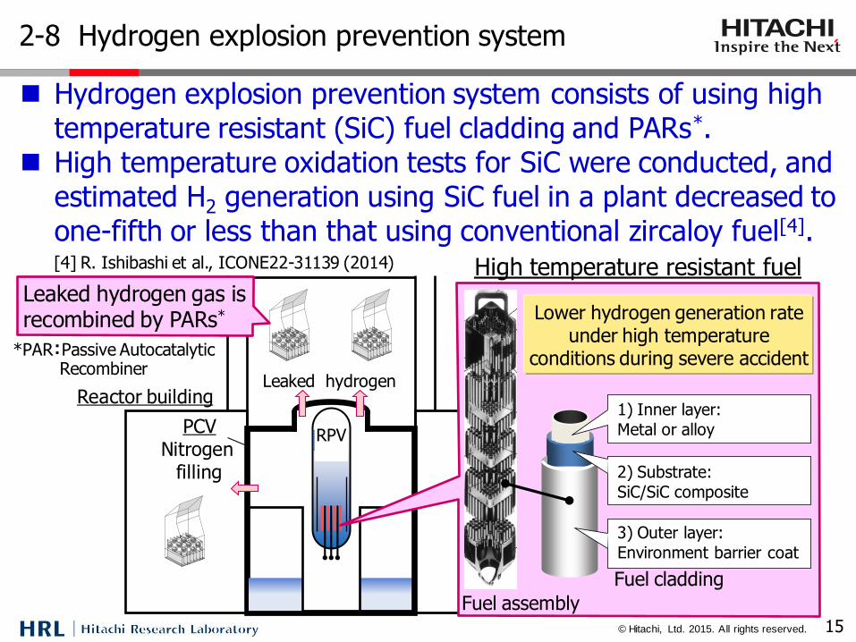
2-8 Hydrogen explosion prevention system
15
Hydrogen explosion prevention system consists of using high temperature resistant (SiC) fuel cladding and PARs*.
High temperature oxidation tests for SiC were conducted, and estimated H2 generation using SiC fuel in a plant decreased to one-fifth or less than that using conventional zircaloy fuel[4].
*PAR:Passive Autocatalytic Recombiner
Reactor building
RPV
High temperature resistant fuel
PCV Nitrogen
filling
Leaked hydrogen
Leaked hydrogen gas is recombined by PARs*
[4] R. Ishibashi et al., ICONE22-31139 (2014)
Fuel assembly
Lower hydrogen generation rate under high temperature
conditions during severe accident
Fuel cladding
1) Inner layer:
Metal or alloy
3) Outer layer:
Environment barrier coat
2) Substrate:
SiC/SiC composite

© Hitachi, Ltd. 2015. All rights reserved.
2-9 Operation support system
16
■ The system covers multiple equipment failures, and it has three functions to reduce the occurrence of operators’ false recognitions and human errors.
■ An accident event identification method and a plant simulation code to predict event progress were developed[5].
Operation Equipment
Control panel
Sensors
Operation support system
Operator
Battery
Main control room
Support staff
Technical support center
①Sensor integrity diagnosis
②Accident event identification
③Progress prediction
Process computer
Functions
[5] M. Kanada et al., ICONE22-31104 (2014)
© Hitachi, Ltd. 2015. All rights reserved.
3. Conclusions
17
© Hitachi, Ltd. 2015. All rights reserved.
3-1 Conclusions
18
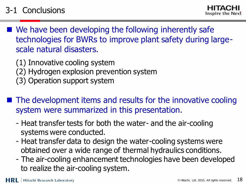
We have been developing the following inherently safe technologies for BWRs to improve plant safety during large-scale natural disasters.
(1) Innovative cooling system (2) Hydrogen explosion prevention system (3) Operation support system
The development items and results for the innovative cooling
system were summarized in this presentation.
- Heat transfer tests for both the water- and the air-cooling systems were conducted.
- Heat transfer data to design the water-cooling systems were obtained over a wide range of thermal hydraulics conditions.
- The air-cooling enhancement technologies have been developed to realize the air-cooling system.
© Hitachi, Ltd. 2015. All rights reserved.
Hitachi Ltd., Hitachi Research Laboratory
Development of Inherently Safe Technologies for BWRs
Feb. 17, 2015
Kazuaki Kitou, Naoyuki Ishida, Akinori Tamura, Ryou Ishibashi, Masaki Kanada and Mamoru Kamoshida
THE END
19