development of attachment for customized...
TRANSCRIPT

DEVELOPMENT OF ATTACHMENT FOR CUSTOMIZED STEERING RACK ON
ONE SEATER DRAG BUGGY
MUHAMMAD SHAHRIN BIN SUHAIMI
A report submitted in partial fulfillment of the requirements
for the award of the
Diploma of Mechanical Engineering
Faculty of Mechanical Engineering
UNIVERSITI MALAYSIA PAHANG
NOVEMBER 2008

iv
ACKNOWLEDGEMENTS
I would like to acknowledge with appreciation the numerous and valuable
comments, suggestions and constructive criticisms from a lot of people around me
during the project period such as my parents, friend, all the instructors at FKM
laboratory and to the very importance men behind this project, En. Mohd Fazli Bin
Ismail as the Supervisor for this project and En. Mohd Farizul Shahidan Bin Rajuli as
the Instructor for this project. Because of their suggestions, support and guidance this
project had achieve the required objectives on time even though facing a lot of problem
during this project period.
I’m very grateful to have a supportive team mate for this project that work for
other major systems on the buggy. The experiences that I gain during this project period
and also the knowledge that I got from the supervisor and instructor for this project are
valuable and very important. Lastly to my beloved parents that always give moral
support for me to stand and continue fighting for my future.

v
ABSTRACT
The title for this project is Development of Attachment for Customized Steering Rack
on One Seater Drag Buggy. This project is under the UMP Mechanical Faculty. The main
target for this project to the final year project student is to design, fabricate and analysis
the customized mechanical part at the steering system of this buggy. This is to achieve
the objective which is the steering system for the buggy is function without any problem.
The steering system is very important to a vehicle to control and to navigate the vehicle
movement direction. The system used mechanical principle to transfer the rotation from
the steering wheel to the wheel through the steer rack that consist mechanical part such
as pinion gear, bar gear and shaft. The analysis of the part is very important to gain the
information on the maximum stress, minimum stress, load, FOS and the application of
each material used to withstand the load. This buggy is design to roll at extreme terrain
such as off-road and mud. The fabrication of the customized part and attachment of the
part must be done properly to withstand the environment used of this vehicle. The other
important aspect during fabrication and attachment process is the driver safety, this
aspect is the priority during the development of the system.

vi
ABSTRAK
Projek Tahun Akhir ini bertajuk Development of Attachment for Customized
Steering Rack on One Seater Drag Buggy. Projek ini merupakan satu teras bagi pelajar tahun
akhir bagi Fakulti Kejuruteraan Mekanikal UMP. Tujuan utama projek tahun akhir ini dijalankan
adalah untuk melatih pelajar supaya berkeupayaan untuk mereka, mencipta dan menganalisis
bahagian-bahagian yang direka supaya mencapai matlamat projek tahun akhir ini iaitu
keupayaan megawal kenderaan ini tanpa masalah. Sistem kawalan kenderaan ini merupakan satu
sistem yang penting dan utama dalam sesebuah kenderaan kerana ia akan menentukan arah
pergerakan kenderaan dan mengawalnya. Sistem ini yang beroperasi secara mekanikal untuk
memindahkan arah putaran pegemudi ke roda melalui rack kemudi yang mengandungi bahagian-
bahagian mekanikal seperti gear pinion, gear bar dan juga shaft. Tujuan menganalisis bahagian-
bahagian yang direka adalah penting kerana untuk memperoleh maklumat tambahan seperti
maximun stress, minimun stress dan juga FOS untuk setiap bahagian yang terlibat dalam operasi
pengemudian ini. Kenderaa buggy ini direka untuk pemanduan di luar jalan raya dan akan
menerima tekanan yang tinggi di bahagian pengemudi. Setiap bahagian perlu mampu
menampung tekanan akibat dari hentakan dan gegaran ketika memandu di kawasan tanah dan
berlopak. Selain dari ketahanan, keselamatan pemandu juga penting dan keutamaan ketika
proses reka cipta di jalankan.
vii
TABLE OF CONTENTS
Page
SUPERVISOR’S DECLARATION ii
STUDENT’S DECLARATION iii
ACKNOWLEDGEMENTS iv
ABSTRACT v
ABSTRAK vi
TABLE OF CONTENTS vii
LIST OF TABLES x
LIST OF FIGURES xi
LIST OF APPENDIX xiii
CHAPTER 1 INTRODUCTION 1
1.1 Project Background 1
1.2 Problem Statement 2
1.3Project Objective 2
1.4 Project Scope 3
CHAPTER 2 LITERATURE REVIEW 5
2.1 Steer System 5
2.2 Type of Steer System Used In This Project 6
2.2.1 Rack and Pinion Steering 6
2.2.2 Power Rack and Pinion 7

viii
CHAPTER 3 METHODOLOGGY 8
3.1 Project Flow Chart 8
3.1.1 Problem and Part Studies 11
3.1.2 Designing Concept and Selection of Best
Concept 11
3.1.2.1 Concepts 11
3.1.2.2 Best Concept Selection 13
3.1.3 Detail Drawing Analysis 14
3.1.4 Selectiong Proper Material For Product 16
3.1.4.1 Material Application 17
3.1.5 Fabrication and Modification 17
3.1.6 Parts Attachment 18
CHAPTER 4 RESULTS AND DISCUSSION 20
4.1 Steering Rack Problem 20
4.2 Gearbox Analysis 22
4.2.1 Fabrication Requirements 23
4.2.1.1 Material Selection 23
4.2.1.2 Concept Selection Method 23
4.2.1.3 Metric Analysis 24
4.2.1.4 Pugh Analysis 25
4.2.2 Gearbox Parts 26
4.2.2.1 Parts Dimensions 27
4.3 Cosmos Xpress Analysis on Gearbox Part 31
4.3.1 Gearbox Chassis Analysis 31
4.3.2 Gearbox Shaft Analysis 33
4.4 Steering Rack Modification 35
ix
CHAPTER 5 CONCLUSION AND RECOMMENDATIONS 36
5.1 Conclusion 36
5.2 Problem Faced During the Project Period 37
5.3 Recommendations 37
REFERENCES 38
APPENDIX 39

x
LIST OF TABLES
TABLE TITLE PAGE
3.1 Concepts Comparison 13
4.1 Metric Rating for Each Concepts 24
4.2 Pugh Rating for Each Concept 25
xi
LIST OF FIGURES
FIGURE TITLE PAGE
1.1 Problem Statement and Gearbox Attachment to Solve
The Rotation Problem 2
2.1 Mechanical Steer System 6
2.2 Mechanical Steer Rack Inside View 6
2.3 Power Steering System 7
3.1 Concept 1 11
3.2 Concept 2 12
3.3 Concept 3 12
3.4 Best Concept 14
3.5 3D Drawing – Shaft 15
3.6 3D Drawing – Pinion Gear 15
3.7 3D Drawing – Chassis 16
3.8 3D Drawing – Full Gearbox Assembly 16
3.9 Gearbox Placement at Buggy Steer System 18
3.10 U-joint Modification 18
3.11 Front view of Buggy Steer System Before Attachment. 19
3.12 Front view of Buggy Steer System After Attachment. 19
4.1 Original Placement of Steering Rack 20
4.2 Modification on the Placement 20
4.3 Pinion Gearbox 21
4.4 The Direction of the Pinion Gear Movement 22
4.5 Component Inside the Gearbox 26
4.6 Shaft Dimension 27

xii
4.7 Pinion Gear Dimension 28
4.8 Gearbox Chassis Dimension 29
4.9 Full Assemble Dimension 30
4.10 Maximum and Minimum Stress Result on the
Gearbox Chassis 31
4.11 Factors of Safety Result at the Chassis 32
4.12 Maximum and Minimum Stress Result on the
Gearbox Shaft 33
4.13 Factors of Safety Result at the Chassis 34
4.14 Tie-Rod Modification 35
5.1 Drag Buggy 36
xiii
LIST OF APPENDIX
APPENDIX TITLE PAGE
A Gantt Chart 39
B Solid Work Isometric Drawing 41

CHAPTER 1
INTRODUCTION
1.1 Project Background
This project was purpose to make an off-road buggy for FELDA usage. It is design
for off-road exploration through estate and can withstand extreme terrain. This buggy
will be proposed for FELDA from UMP-MECHANICAL FACULTY after the
fabrication, modification and basic analysis completed. This project was divided into
three major parts for PTA students to handle under En. Mohd Fazli Bin Ismail
(supervisor). Overall this project required the skills of designing, knowledge of the
system and analysis of each component or part in the system.

2
1.2 Problem Statement
This Project will need modification and fabrication of extra part for the buggy’s
steering system. This is because on early development of this project the steering system
had a rotation problem on the steer rack. The rotation motion of the rack is inverted with
the front wheel steer direction. The main focus is to design and fabricate a gear box that
will convert the rotation motion before it transfer to the steer rack. Others are to
modified aftermarket steer system to perfectly fit when attaching the system with the
buggy main chassis.
Figure 1.1
Problem statement and gearbox attachment to solve the problem
1.3 Project Objective
The objective of this project is to design, fabricate and modified the steering system
on the buggy. By using the mechanical steer system, installation of additional custom
part is required to convert the rotation of the steering wheel before it transfer to the
steering rack.
Modified – universal joint, alignment rod and steering rack.
Fabricate – gear box.

3
1.4 Project Scope
Project Scope is the required step to gain knowledge and understanding on the main
focus on the project.
The project scopes are:-
a) Investigation of the problem.
In this process, the main idea is to find the problems that occur on the steering
system. Identifying latent or hidden problems on the buggy’s steer system and then list
down the possibility solution for solving the problem.
b) Set target specifications
Base on steering types and benchmarks (Benchmarking is information on
competing products gathered to support the positioning). Develop metrics for each types
of steering to help identify the specification of the system. Set ideal and acceptable
values for each steer system.
c) Conceptualization.
Concentrate on designing the assembly line and create custom part for the steer
system by making simple sketches known as thumbnail sketches of each concept. This is
the brainstorming on the designing of costume made part that will fulfill the required
specification needed for the part.
4
d) Further refinement and final concept selection.
Draw in 2D or 3D for part studies and for testing to the proposed product
features and functionality (solid work).The Drawing will be analyze by using COSMOS
Xpress to get the required information such as maximum stress, minimum stress and the
factor of safety of each part.
e) Control drawing
In this stage, the main focus is to gain information on document functionally,
features, size, surface finish and key dimension on each part. This information is helping
in fabricate the final design models for the project.

5
CHAPTER 2
LITERATURE REVIEW
2.1 Steer System
Steering system in automobiles are build from several component such as
steering wheel, gears, linkages, and other components used to control the direction of a
vehicle's motion. Because of friction between the front tires and the road, especially in
parking, effort is required to turn the steering wheel. To lessen the effort required, the
wheel is connected through a system of gears to components that position the front tires.
The gears give the driver a mechanical advantage. Various types of gear assemblies,
none with any decisive advantages over the others, are used, although some
manufacturers prefer a rack-and-pinion system. In faster, heavier cars the amount of
force required to turn the tires can be very great. Many of these cars use a power-
steering system. The system contains a hydraulic booster, which operates when the
engine is running and supplies most of the necessary force when the driver turns the
wheel.
6
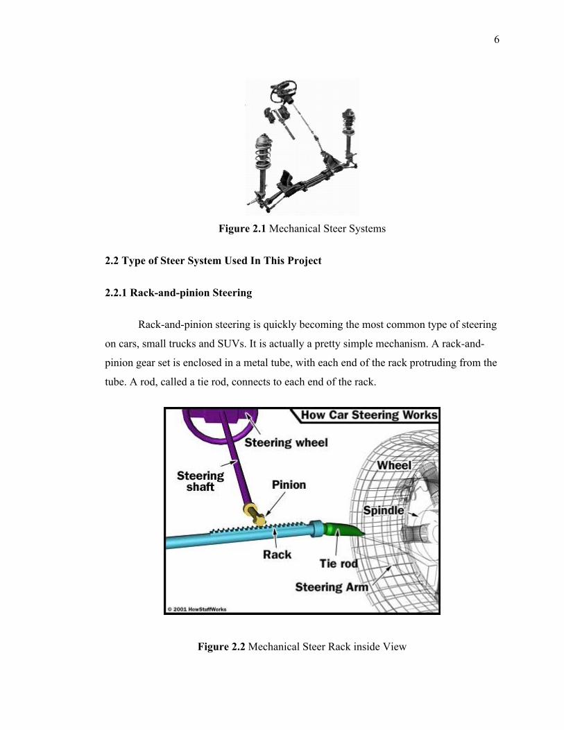
Figure 2.1 Mechanical Steer Systems
2.2 Type of Steer System Used In This Project
2.2.1 Rack-and-pinion Steering
Rack-and-pinion steering is quickly becoming the most common type of steering
on cars, small trucks and SUVs. It is actually a pretty simple mechanism. A rack-and-
pinion gear set is enclosed in a metal tube, with each end of the rack protruding from the
tube. A rod, called a tie rod, connects to each end of the rack.
Figure 2.2 Mechanical Steer Rack inside View

7
The pinion gear is attached to the steering shaft. When you turn the steering wheel, the
gear spins, moving the rack. The tie rod at each end of the rack connects to the steering
arm on the spindle (see diagram above).
The rack-and-pinion gear set does two things:
It converts the rotational motion of the steering wheel into the linear motion
needed to turn the wheels.
It provides a gear reduction, making it easier to turn the wheels.
2.2.2 Power Rack-and-pinion
When the rack-and-pinion is in a power-steering system, the rack has a slightly different
design.
Figure 2.3 Power Steering System
Part of the rack contains a cylinder with a piston in the middle. The piston is connected
to the rack. There are two fluid ports, one on either side of the piston. Supplying higher-
pressure fluid to one side of the piston forces the piston to move, which in turn moves
the rack, providing the power assist.

8
CHAPTER 3
PROJECT METHODOLOGY
3.1 Project Flow
Methodology is the method that been used from early project develop until the
end product release. It consist several stage of conducting this whole project. This flow
will explain detail about each step of Industrial Design Method in developing new
product that will achieve the required specification. To make sure this project complete
on schedule, flow chart is important to assure all the planning running smoothly. The
processes start with doing researches on the types of steer systems to gain more
knowledge about the principle of the steer rack. The next step is doing metric and pugh
analysis to select the best type of steering rack and propose to the supervisor before
starting the next steps of the process. Brainstorming to get various concepts and do
analysis of each concept to determine the best concept for the fabrication process. The
concept will be converted to the 3D drawing for further studies on the dimension and the
logical movement. The testing of the product will be done after the fabrications are
finish. The last step is to compile all the information for presentation and report
submission.

9
a) Flow Chart START
Search on MultipleSteer types
No
Enough Information?
Yes
No
Enough
Information?
Yes
Page A
Detail Research on the Type
Chosen
PUGH Analysis & Matrix Rating
Proposal
10
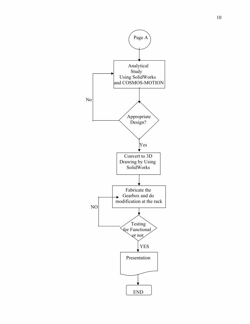
Page A
Analytical Study
Using SolidWorks and COSMOS-MOTION
No
Appropriate Design?
Yes
Convert to 3D Drawing by Using
SolidWorks
Fabricate the Gearbox and do
modification at the rackNO
Testing for Functional
or not
YES
Presentation
END

11
3.1.1 Problem and Part Studies
This is the first step of the flow. This is to identify the problems in the system
and list down the causes of the problems. It also includes the studies of each part in the
steering system to gain more knowledge and understanding on the principal of each
component.
3.1.2 Designing Concept and Selection of Best Concept
This stage will need a lot of new concept develop in sketches to help in
development of the best concept. This is because the concepts that have been develop
from sketches are being compared in several aspects such as size, strength, material and
ergonomic.
3.1.2.1 Concepts
Figure 3.1:
CONCEPT 1 - Rotation transfer by belting concept

12
Figure 3.2:
CONCEPT 2 - Twin gear rotation concept
Figure 3.3:
CONCEPT 3 - Direct gear connection concept
13
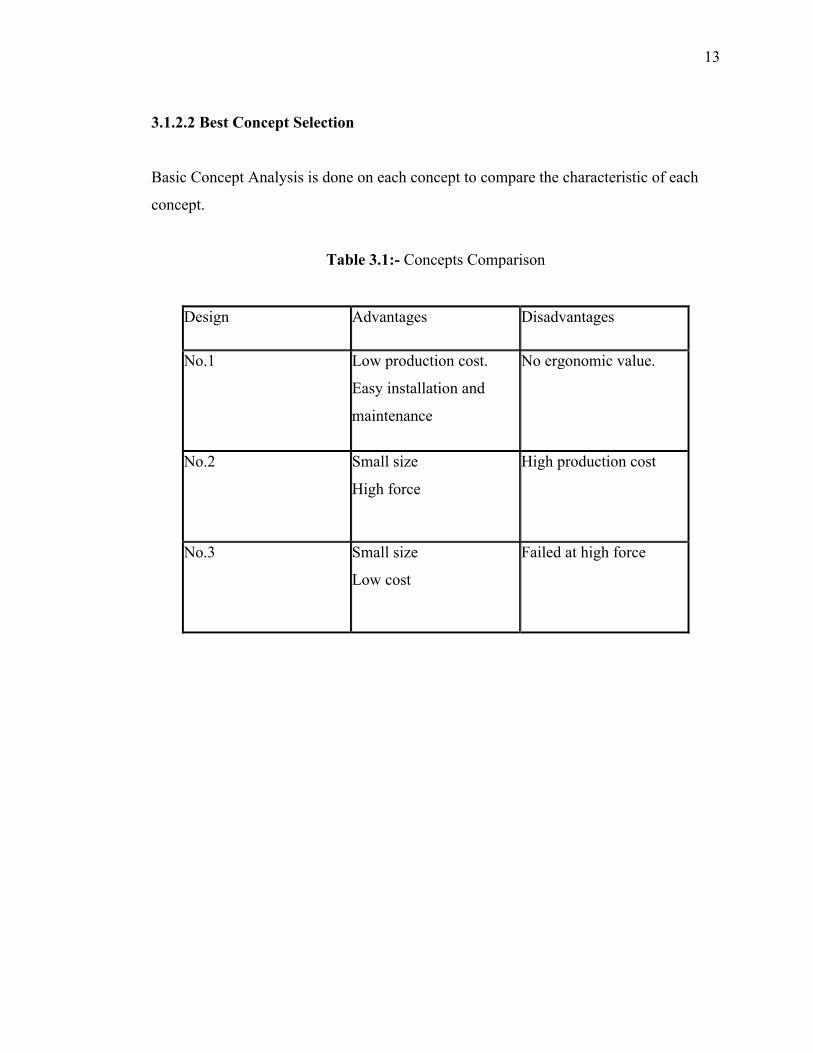
3.1.2.2 Best Concept Selection
Basic Concept Analysis is done on each concept to compare the characteristic of each
concept.
Table 3.1:- Concepts Comparison
Design Advantages Disadvantages
No.1 Low production cost.
Easy installation and
maintenance
No ergonomic value.
No.2 Small size
High force
High production cost
No.3 Small size
Low cost
Failed at high force