development of an ethercat enabled digital servo ... · gbt memo 281 development of an ethercat...
TRANSCRIPT
GBT Memo 281
Development of an EtherCAT enabled digital servo controller for the
Green Bank Telescope
Peter G. Whiteisa, Melinda J. Melloa aNational Radio Astronomy Observatory, PO Box 2, Green Bank, WV, USA 24944-0002
ABSTRACT
EtherCAT (Ethernet for Control Automation Technology) is gaining wide spread popularity in the automation industry as a real time field bus based on low cost, Ethernet hardware. EtherCAT maximizes use of 100Mbps Ethernet hardware by using a collision free ring topology, efficient Ethernet frame utilization (> 95%), and data exchange “on the fly”. These characteristics enable EtherCAT to achieve Master to Slave node data exchange rates of > 1000 Hz.
The Green Bank Telescope, commissioned in 2000, utilizes an analog control system for motion control of 8 elevation and 16 azimuth motors. This architecture, while sufficient for observations at frequencies up to 50GHz, has significant limitations for the current scientific goals of observing at 115GHz. Accordingly, the Green Bank staff has embarked on a servo upgrade project to develop a digital servo system which accommodates development and implementation of advanced control algorithms.
This paper describes how the new control system requirements, use of existing infrastructure and budget constraints led us to define a distributed motion control architecture where EtherCAT real-time Ethernet was selected as the communication bus.
Finally, design details are provided that describe how NRAO developed a custom EtherCAT-enabled motor controller interface for the GBT’s legacy motor drives in order to provide technical benefits and flexibility not available in commercial products.
Keywords: EtherCAT, Real-time Ethernet, Motor Controller, GBT, Green Bank Telescope
1. INTRODUCTION
A number of large radio telescopes (Large Millimeter Telescope, 34m Deep Space Network, etc) have proposed advanced servo architectures. These are generally model-based systems incorporating Linear-Quadratic-Gaussian (LQG) controllers in either the position loops or the velocity loops, or both. Our existing servo system is based on an analog lag compensated rate loop and a lead-lag compensated position loop, and this architecture offers limited opportunity for improvements. We intend to replace the existing servo with a new servo system.1
The following sections outline the process by which the Green Bank Staff developed a new digital servo system, using EtherCAT as a key enabling technology.
The architectural development of the digital controller is described in Section 2. This includes a comparison-contrast of architectural choices, budget limitations, as well as the control parameters which guided the technology selection.
The realization of hardware and software components which comprise the digital control system is described in Section 3. Therein, we summarize the development of EtherCAT enabled BALDOR drives, motor controller firmware, network topology of the EtherCAT enabled devices and finally integration with the host controller (Central Control Unit).
Finally, Section 4 contains the current state of the project, along with some near term objectives.
2. ARCHITECTURAL DEVELOPMENT
2.1 Distributed vs Centralized System
Traditionally, control systems utilized a centralized architecture wherein discrete field devices (switches, sensors,
etc) are hardwired to a terminal block which interfaces to A/D, D/A, and Digital I/O cards located in a central control
cabinet. A microcontroller would read and write data from the I/O cards in order to achieve closed loop control over the
system. This approach, while effective, often meant spending considerable installation effort making long wire runs
from the central control cabinet to the field. Adding additional field devices meant running more wire, and perhaps
adding I/O cards. Finally, aging issues with wiring and connectors as well as noise induction contribute to an increased
long term maintenance effort.
More recently, field bus technologies have given control system developers an advantage via deployment of
intelligent field devices capable of communicating synchronously over Profibus, CAN, Ethernet, EtherCAT or any
number of field-bus protocols. Data is typically converted to digital form at the field device. Exchange of I/O from the
controller to the field devices can often be accomplished over a single cable using a “ring” topology.
NRAO decided early in the servo replacement project to migrate away from the traditional centralized control
approach to a distributed control system based on modern field-bus technologies. We felt that this approach would
allow us to minimize field wiring, substantially reducing the deployment and ongoing maintenance effort. Furthermore,
the modularity of the distributed approach allows us to add new components to the system without significant change to
the system architecture.
2.2 Budget
The original budget for the servo replacement effort precluded replacement of our existing 24 BALDOR drives with
off the shelf intelligent servo drives. Thus, we decided a more cost effective alternative was to modify the existing drive
to allow I/O exchange to occur at the drive itself, through inclusion of a low cost microcontroller along with analog and
digital signal handling components.
2.3 Sample Rate
Control requirements for the servo replacement effort were fundamentally derived from the 70 Hz bandwidth of the
existing servo drives. “The minimum acceptable band width was determined as the Nyquist rate to support this 70 Hz
bandwidth (140 SPS) multiplied by an over-determination factor (typically 5 to 10 for digital controllers) of 5. This
produced a minimum requirement of 700 samples (SPS). To give some margin to this minimum acceptable rate, the
target sample rate was rounded up to 1KSPS. Determination of the bandwidth requirement involved a survey of the
sample rates/bandwidth of GBT sensors/controllers”2
2.4 Field Bus Selection
Selection of an appropriate Field Bus was largely dependent on 1) support for sample rate (1KSPS), 2) low jitter (<
10% cycle time) 3) open standard, 4) broad vendor support.
A survey of current “open” field-bus technologies resulted in several that met our criteria. Among them, were
Ethernet Powerlink, Profibus IRT, Sercos III, and EtherCAT. Multiple vendor inquiries and Internet research finally
resulted in selecting EtherCAT, for a first stage evaluation. Characteristics that made EtherCAT an attractive choice
were a wide supplier base, high speed/low jitter, and use of standard Ethernet components. We found a supplier
(Hilscher) that offered an EtherCAT interface ASIC in a 3 x 7 cm form factor ideally suited to our custom design.
2.5 EtherCAT
2.5.1 Communication Model
The EtherCAT communication model is realized as a master/slave relationship. One EtherCAT node is designated
as the master and is responsible for initiating data transfers to the EtherCAT slave nodes. Timing of data transfers is
controlled entirely by the EtherCAT master. For this reason, the EtherCAT master’s computing platform should be
capable of deterministic, real-time performance to ensure low-jitter cyclical transfers.
2.5.2 Data Exchange “On The Fly”
One characteristic that differentiates EtherCAT from other field bus technologies is the ability to exchange data
within an Ethernet frame as the frame passes through a device’s physical layer. “With EtherCAT, the Ethernet packet or
frame is no longer received, then interpreted and copied as process data at every node. The EtherCAT slave devices read
the data addressed to them while the telegram passes through the device. Similarly, input data are inserted while the
telegram passes through. The frames are only delayed by a fraction of a microsecond in each node, and many nodes -
typically the entire network - can be addressed with just one frame.” 3
2.5.3 Network Configuration
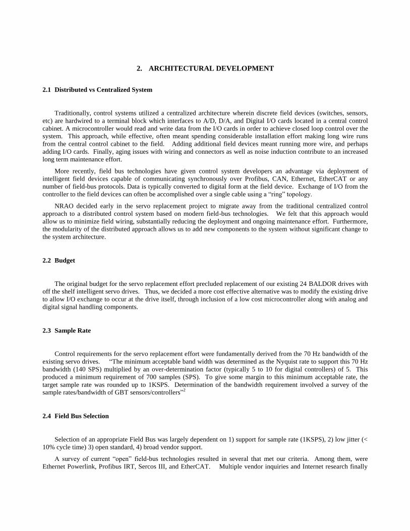
EtherCAT network configuration is typically facilitated through use of a configuration tool, by which slave device
descriptions are generated along with an aggregate description of the network (Figure 1). The EtherCAT network
description is output to an XML formatted configuration file which is used at link initialization time. The configuration
file contains information about each slave’s dataset including the frame offset and size of each data member. The
EtherCAT Master transmits this information to slaves during link initialization. Each slave uses these frame offsets to
facilitate “on the fly” data exchange during normal operation.
The configuration tool is also critical for optimizing system performance through use of algorithms that efficiently
organize all slave data into a single Ethernet frame.
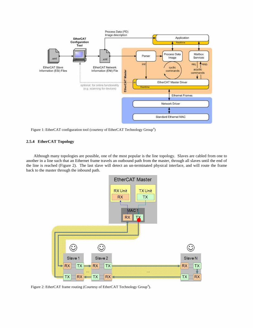
Figure 1: EtherCAT configuration tool (courtesy of EtherCAT Technology Group4)
2.5.4 EtherCAT Topology
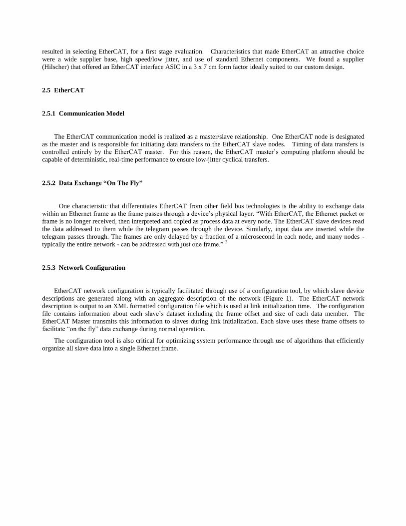
Although many topologies are possible, one of the most popular is the line topology. Slaves are cabled from one to
another in a line such that an Ethernet frame travels an outbound path from the master, through all slaves until the end of
the line is reached (Figure 2). The last slave will detect an un-terminated physical interface, and will route the frame
back to the master through the inbound path.
Figure 2: EtherCAT frame routing (Courtesy of EtherCAT Technology Group4).
3. DIGITAL SERVO DESIGN
3.1 Design Partitioning
The design effort consisted of a partitioning of the digital
servo system into several functional groups which, once
interfaces were defined, could be developed in a semi-
autonomous fashion. The primary functional system blocks
consisted of 1) an analog interface card to the motor drive 2) a
digital interface card between the EtherCAT network and the
analog card and 3) a Central Control Unit (CCU). The analog
and digital interface cards are sometimes collectively known as
the Motor Controller Interface (MCI) cards.
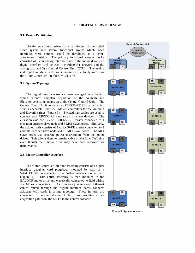
3.2 System Topology
The digital servo electronics were arranged in a fashion
which enforces complete separation of the Azimuth and
Elevation axis components up to the Central Control Unit. The
Central Control Unit contains two CIFX50-RE PCI cards5 which
serve as separate EtherCAT Master controllers for the Azimuth
and Elevation rings (Figure 3). Twisted pair cables are used to
connect each CIFX50-RE card to all its slave devices. The
elevation axis consists of 1 CIFX50-RE master connected to 1
elevation encoder slave node and 8 MCI slave nodes. Similarly,
the azimuth axis consists of 1 CIFX50-RE master connected to 1
azimuth encoder slave node and 16 MCI slave nodes. The MCI
slave nodes use separate power distribution from the motor
drives. This allows them to remain active on the EtherCAT ring
even though their motor drive may have been removed for
maintenance.
3.3 Motor Controller Interface
The Motor Controller Interface assembly consists of a digital
interface daughter card piggyback mounted by way of a
SAMTEC 50 pin connector to an analog interface motherboard
(Figure 4). This entire assembly is then mounted to the
BALDOR motor drive and electrically connected to field wiring
via Molex connectors. As previously mentioned, Ethernet
cables routed through the digital interface cards connects
adjacent MCI cards in a line topology. These in turn, are
connected to the Central Control Unit, thus providing a data
acquisition path from the MCI’s to the control software.
Figure 3: System topology
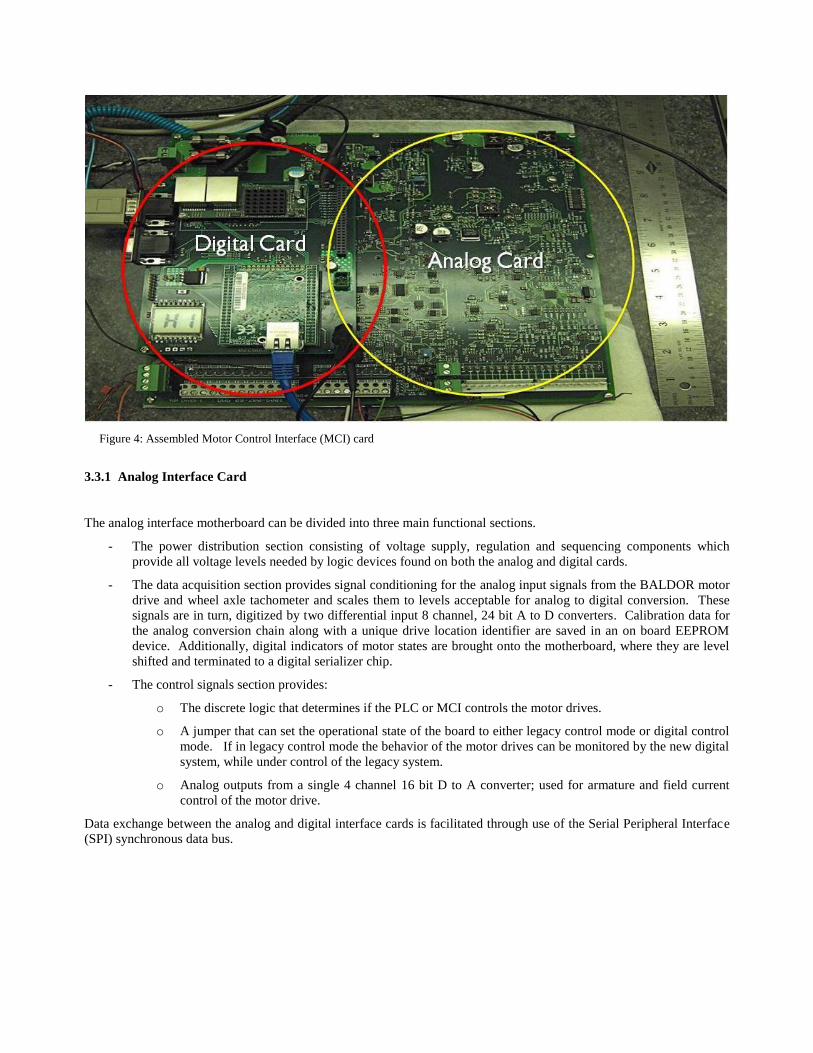
Figure 4: Assembled Motor Control Interface (MCI) card
3.3.1 Analog Interface Card
The analog interface motherboard can be divided into three main functional sections.
- The power distribution section consisting of voltage supply, regulation and sequencing components which
provide all voltage levels needed by logic devices found on both the analog and digital cards.
- The data acquisition section provides signal conditioning for the analog input signals from the BALDOR motor
drive and wheel axle tachometer and scales them to levels acceptable for analog to digital conversion. These
signals are in turn, digitized by two differential input 8 channel, 24 bit A to D converters. Calibration data for
the analog conversion chain along with a unique drive location identifier are saved in an on board EEPROM
device. Additionally, digital indicators of motor states are brought onto the motherboard, where they are level
shifted and terminated to a digital serializer chip.
- The control signals section provides:
o The discrete logic that determines if the PLC or MCI controls the motor drives.
o A jumper that can set the operational state of the board to either legacy control mode or digital control
mode. If in legacy control mode the behavior of the motor drives can be monitored by the new digital
system, while under control of the legacy system.
o Analog outputs from a single 4 channel 16 bit D to A converter; used for armature and field current
control of the motor drive.
Data exchange between the analog and digital interface cards is facilitated through use of the Serial Peripheral Interface
(SPI) synchronous data bus.
3.3.2 Digital Interface Card
3.3.2.1 Hardware
As previously mentioned, the digital interface card is piggyback mounted to the analog interface card using a 50
pin connector to route SPI and chip select signals to the SPI devices present in the analog card. Additionally, power is
supplied through the connector from the analog card.
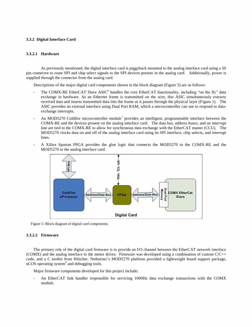
Descriptions of the major digital card components shown in the block diagram (Figure 5) are as follows:
- The COMX-RE EtherCAT Slave ASIC6 handles the core EtherCAT functionality, including “on the fly” data
exchange in hardware. As an Ethernet frame is transmitted on the wire, this ASIC simultaneously extracts
received data and inserts transmitted data into the frame as it passes through the physical layer (Figure 1). The
ASIC provides an external interface using Dual Port RAM, which a microcontroller can use to respond to data-
exchange interrupts.
- An MOD5270 Coldfire microcontroller module7 provides an intelligent, programmable interface between the
COMX-RE and the devices present on the analog interface card. The data bus, address buses, and an interrupt
line are tied to the COMX-RE to allow for synchronous data exchange with the EtherCAT master (CCU). The
MOD5270 clocks data on and off of the analog interface card using its SPI interface, chip selects, and interrupt
lines.
- A Xilinx Spartan FPGA provides the glue logic that connects the MOD5270 to the COMX-RE and the
MOD5270 to the analog interface card.
Figure 5: Block diagram of digital card components.
3.3.2.2 Firmware
The primary role of the digital card firmware is to provide an I/O channel between the EtherCAT network interface
(COMX) and the analog interface to the motor drives. Firmware was developed using a combination of custom C/C++
code, and a C toolkit from Hilscher. Netburner’s MOD5270 platform provided a lightweight board support package,
uCOS operating system9 and debugging tools.
Major firmware components developed for this project include:
- An EtherCAT link handler responsible for servicing 1000Hz data exchange transactions with the COMX
module.
- A Data Acquisition component to handle ADC interrupts, data conversions and buffering for network
exchange.
- Wheel axle encoder velocity calculations (future use).
- A Telnet command interface for administrative functions.
- An S-Record loader for firmware updates.
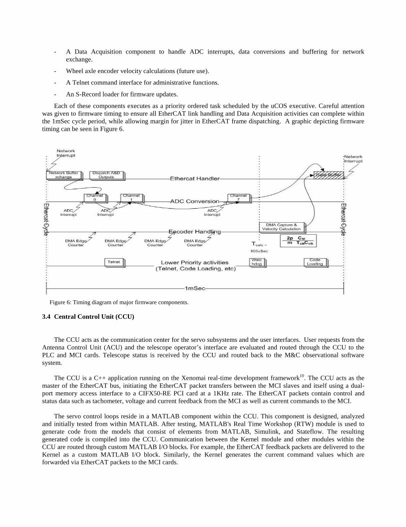
Each of these components executes as a priority ordered task scheduled by the uCOS executive. Careful attention
was given to firmware timing to ensure all EtherCAT link handling and Data Acquisition activities can complete within
the 1mSec cycle period, while allowing margin for jitter in EtherCAT frame dispatching. A graphic depicting firmware
timing can be seen in Figure 6.
Figure 6: Timing diagram of major firmware components.
3.4 Central Control Unit (CCU)
The CCU acts as the communication center for the servo subsystems and the user interfaces. User requests from the
Antenna Control Unit (ACU) and the telescope operator’s interface are evaluated and routed through the CCU to the
PLC and MCI cards. Telescope status is received by the CCU and routed back to the M&C observational software
system.
The CCU is a C++ application running on the Xenomai real-time development framework10
. The CCU acts as the
master of the EtherCAT bus, initiating the EtherCAT packet transfers between the MCI slaves and itself using a dual-
port memory access interface to a CIFX50-RE PCI card at a 1KHz rate. The EtherCAT packets contain control and
status data such as tachometer, voltage and current feedback from the MCI as well as current commands to the MCI.
The servo control loops reside in a MATLAB component within the CCU. This component is designed, analyzed
and initially tested from within MATLAB. After testing, MATLAB's Real Time Workshop (RTW) module is used to
generate code from the models that consist of elements from MATLAB, Simulink, and Stateflow. The resulting
generated code is compiled into the CCU. Communication between the Kernel module and other modules within the
CCU are routed through custom MATLAB I/O blocks. For example, the EtherCAT feedback packets are delivered to the
Kernel as a custom MATLAB I/O block. Similarly, the Kernel generates the current command values which are
forwarded via EtherCAT packets to the MCI cards.
4. CURRENT STATUS
To date, all major components of the digital servo system have been deployed to the GBT and the field wiring
completed. The MCI cards are electrically in the loop with the legacy system. While the legacy system is still used for
telescope control, the CCU application software is using EtherCAT to monitor the motor drives while the telescope is in
use. Our near term goal is to collect datasets for use in validating the response of the new digital control kernel.
Additionally, a simulator has been developed that consists of the CCU, EtherCAT and 24 MCI digital cards. The
digital card firmware implements a state space derived model of the BALDOR motor drive response which allows for
non-intrusive development of CCU application and control kernel software.
5. CONCLUSIONS
Since the digital servo system described here is not fully deployed, it is premature to draw firm conclusions
regarding the use of EtherCAT in our design. Overall, the hardware deployment effort benefited from a significant
reduction of field wiring and improved component maintenance. The design of the EtherCAT ASIC into the drive
electronics presented a learning curve for the software engineering team which we hope pays off as EtherCAT is reused
for future designs. EtherCAT is being considered as an ideal technology choice for upgrades to the GBT secondary
optics systems, which are located over 175 meters above the central control unit.
6. ACKNOWLEDGMENTS
Many have contributed to the larger body of digital servo design work. Kevin Sexton was primary on the analog
board design and overall control systems requirements and development. Tim Weadon initiated the EtherCAT
evaluation effort, and was primary designer of the digital interface card. Joe Brandt and Melinda Mello developed the
Central Control Unit application software and provided substantial help with debug and performance analysis of
EtherCAT. Richard Prestage and Marty Bloss helped to keep the effort on track and provided wisdom when it was
needed most. Lastly, we’d like to thank John Ford for steering us toward EtherCAT early on, and for his encouragement
in writing this paper.
REFERENCES
[1] Servo Improvements project charter, NRAO 2009.
[2] R. K. Sexton, personal correspondence on control systems requirements, NRAO.
[3] http://en.wikipedia.org/wiki/EtherCAT
[4] http://www.ethercat.org
[5] cifX- Communication Interface, http://hilscher.com/files_datasheets/D_4ddb7131b2505_uk.pdf
[6] comX – Flexible Communication Module for Automation,
http://www.hilscher.com/files_datasheets/D_445f15df7224e_uk.pdf.
[7] MOD5270 – NetBurner’s High Performance Embedded Network Core Module,
http://www.netburner.com/downloads/mod5270/mod5270_datasheet_pinout_diagram.pdf.
[8] Xilinx Spartan 3AN – FPGAs, http://www.xilinx.com/publications/prod_mktg/pn002011.pdf
[9] uC/OS Kernel, http://micrium.com/page/products/rtos/os-ii
[10] Xenomai: Real-Time Development Framework for Linux, http://www.xenomai.org/index.php/Main_Page