development of a multitarget tracking system for paramecia
TRANSCRIPT

Development of a multitarget tracking system for parameciaYu-Sing Yeh, Ke-Nung Huang, Sun-Lon Jen, Yan-Chay Li, and Ming-Shing Young Citation: Review of Scientific Instruments 81, 074302 (2010); doi: 10.1063/1.3460266 View online: http://dx.doi.org/10.1063/1.3460266 View Table of Contents: http://scitation.aip.org/content/aip/journal/rsi/81/7?ver=pdfcov Published by the AIP Publishing Articles you may be interested in Inspecting and locating foreign body in biological sample by laser confocal feedback technology Appl. Phys. Lett. 103, 101909 (2013); 10.1063/1.4820812 On random search: Collection kinetics of Paramecia into a trap embedded in a closed domain Am. J. Phys. 78, 574 (2010); 10.1119/1.3293976 How to track protists in three dimensions Rev. Sci. Instrum. 80, 014301 (2009); 10.1063/1.3053242 Submersible digital in-line holographic microscope Rev. Sci. Instrum. 77, 043706 (2006); 10.1063/1.2193827 Oscillatory magnetic bead rheometer for complex fluid microrheometry Rev. Sci. Instrum. 72, 3626 (2001); 10.1063/1.1394185
This article is copyrighted as indicated in the article. Reuse of AIP content is subject to the terms at: http://scitationnew.aip.org/termsconditions. Downloaded to IP:
130.216.129.208 On: Sat, 06 Dec 2014 02:43:55
Development of a multitarget tracking system for parameciaYu-Sing Yeh,1 Ke-Nung Huang,2 Sun-Lon Jen,2 Yan-Chay Li,3 and Ming-Shing Young1,a�
1Department of Electrical Engineering, National Cheng Kung University, Tainan, 701 Taiwan2Department of Electronic Engineering, I-Shou University, Kaohsiung, 840 Taiwan3Department of Biomedical Engineering, I-Shou University, Kaohsiung, 840 Taiwan
�Received 4 January 2010; accepted 14 June 2010; published online 21 July 2010�
This investigation develops a multitarget tracking system for the motile protozoa, paramecium. Thesystem can recognize, track, and record the orbit of swimming paramecia within a 4 mm diameterof a circular experimental pool. The proposed system is implemented using an optical microscope,a charge-coupled device camera, and a software tool, Laboratory Virtual InstrumentationEngineering Workbench �LABVIEW�. An algorithm for processing the images and analyzing thetraces of the paramecia is developed in LABVIEW. It focuses on extracting meaningful data in anexperiment and recording them to elucidate the behavior of paramecia. The algorithm can alsocontinue to track paramecia even if they are transposed or collide with each other. The experimentdemonstrates that this multitarget tracking design can really track more than five paramecia andsimultaneously yield meaningful data from the moving paramecia at a maximum speed of 1.7mm/s. © 2010 American Institute of Physics. �doi:10.1063/1.3460266�
I. INTRODUCTION
Advances in biomedical science and technology have in-creased the availability of the observation and control of mi-croorganisms, which are utilized extensively as microcon-trollers, biosensors, and in environmental monitoring.Various investigations of galvanotaxis1–9 and chemotaxis9–16
were used to examine the characteristics of microorganism,especially paramecia in the fields of medical science, elec-trophysiology, biomedical science, and toxicology. In someresearches, the investigators have attempted to developmethods for tracking microorganisms.17–20 Paramecium, aciliate protozoan, can reproduce by splitting and is easilybred in any laboratory for observation and experimentation.Because of the aforementioned characteristics, parameciacan be used simply and inexpensively, occupying less spacethan conventional bioassays.13,14,16 Experiments on parame-cia are frequently conducted in a narrow experimental poolfor their behavior.6,14,16 Recent investigations have involvedthe observation and measurement of theparamecium1,6,11,15,20 to study locomotor behavior and mor-phological abnormalities in the detection ofpollution.10,12–14,20 Researchers have also developed variouseffective methods such as the self-window algorithm17–20 fortracking paramecium. However, they always depend on somespecial and expensive instruments. A system that can accu-rately measure the behavior of paramecia is essential. Itshould be simple, user-friendly, and widely adopted inbioassays.14,15 Related studies have developed algorithms totrack and to analyze the behavior of only oneparamecium2,4,5,7,8,17–19 even when various paramecia arealso in the field of the observed pool. Paramecia are too tinyto allow their number in an experimental pool to be con-trolled. If the behavioral measurement was conducted on a
single paramecium, then useful data will be deficient in theexperiment. If a system could be developed to track numer-ous targets simultaneously, then experiments would take lesstime, require less human effort, and fewer other resources,such as microorganism being and medicinal resources.
Studies of multitarget tracking often utilize a coloredmarker that is attached to the target to help track its positionand facilitate multitarget tracking against complexbackgrounds.21,22 However, attaching a colored marker toparamecia is impossible and dyeing them may affect theirmotion, behavior, and even existence. To solve these prob-lems, a multitarget algorithm for tracking paramecia withoutan attached or dyed marker must be developed. This inves-tigation studies an algorithm for recognizing and tracking themotion of paramecia. By enlarging the field of view, thesystem can track and record the orbits in a multitarget man-ner using various image processing procedures for detailedanalysis. By analyzing numerous video fields, the XY coor-dinates of these paramecia can be recorded explicitly. Thesystem utilizes a biological optical microscope, a charge-coupled device �CCD� camera, and a personal computer torecord an image, which is used to analyze the behavior of theparamecia. The multitarget tracking algorithm is developedin LABVIEW with reference to the discrepancy among varioussituations of complex background.
II. METHODS
A. The multitarget tracking system
In this study, a multitarget tracking system for parameciawas developed. It includes the following subsystems: �1� forobserving a panoramic view of the paramecia completely, aningenious circular experimental pool with 4 mm diameter isself-made on a microscope slide by a puncher and cuttingsheet. �2� A FINDER SMK-1600T �Finder Optics Interna-tional Ltd., Taiwan� trinocular biological microscope with aa�Electronic mail: [email protected].
REVIEW OF SCIENTIFIC INSTRUMENTS 81, 074302 �2010�
0034-6748/2010/81�7�/074302/8/$30.00 © 2010 American Institute of Physics81, 074302-1
This article is copyrighted as indicated in the article. Reuse of AIP content is subject to the terms at: http://scitationnew.aip.org/termsconditions. Downloaded to IP:
130.216.129.208 On: Sat, 06 Dec 2014 02:43:55
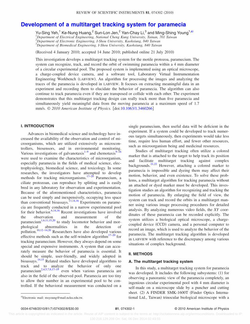
4� target lens, which is used to magnify the paramecia im-ages and enable the paramecia to be observed by the nakedeye. �3� An AVT Guppy F-146C �ALLIED Vision Technolo-gies GMBH, Germany� CCD camera with an IEEE 1394interface, which is used to record the video images of para-mecia. �4� A computerized video tracking system, which wasdesigned to help observe and record the track of each para-mecium. �5� A man-machine interface, which was programedusing LABVIEW software to enable the multitarget trackingsystem be used to locate and track the paramecia. �6� Animage processing procedures which include color spacetransformation, spatial domain, background subtraction, andmorphology. �7� A multitarget positioning algorithm whichcan track N paramecia. The block diagram of the multitargettracking system is shown in Fig. 1.
The size of the image acquired is 1392�1040 pixelsand the image format is 8 bit monoimage, while the transferrate is 400 Mbit/s and the average frame rate is approxi-mately 17.7 frames/s. The measuring region is the region ofinterest �ROI� with a radius of 510 pixels to ensure that nounwanted image is captured. Before the analysis, the systembegins by saving the last frame and converting it into a bit-map �BMP� file. This BMP image is saved as a backgroundimage that is used in the background subtraction. Thereafter,in the analysis stage, the program processes the next image.Additionally, the program can save data of the locations andthe track, as well as produce data that can be used to analyzethe locomotor behavior of the paramecia. After parameciawere recognized and located using aforementioned imageprocessing procedures, the multitarget positioning algorithmwhich can track N paramecia was applied.
B. Image processing
In feature extraction, digital image processing is adoptedto recognize the shape of the paramecia. The image is ana-lyzed by a software developed in LABVIEW8.6 �National In-struments, USA�, a graphical programming developmenttool, which can be used to transform, analyze, and compressan image. In this study, the system is divided into two parts,which are shown in Fig. 1: preprocessing and image analysis.In the preprocessing stage, the system processes images that
record the behavior of the paramecia as an audio video in-terleave �AVI� file in LABVIEW. The measured region is indi-cated as an ROI to prevent the capturing of unwanted im-ages, increasing the effectiveness of data processing,reducing the required human resources and time. LABVIEW
software is adopted to develop the human-machine interfacefor image analysis. The program utilizes paramecia imagingprocessing and analyzing procedures to determine the resultsof registration, feature extraction, and tracking. The follow-ing section discusses these three processes in greater detail.
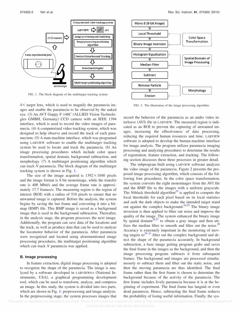
The subprogram built using LABVIEW software analyzesthe video image of the paramecia. Figure 2 presents the pro-posed image processing algorithm, which consists of the fol-lowing four procedures. In the color space transformation,the system converts the eight monoimages from the AVI fileand the BMP file to the images with a uniform grayscale.The Niblack threshold algorithm23 is applied to compute thelocal thresholds for each pixel based on its local statisticsand seek the dark objects to make the intended target standout against the complex background.24,25 The binary imageinversion is then applied to filter out noise and improve thequality of the image. The system enhanced the binary imageby spatial domain26,27 to obtain a gray image and then uti-lizes the median filter to smooth and filter out the noise.28
Accuracy is extremely important in the monitoring of mov-ing targets to29–31 filter out the complex background and de-tect the shape of the paramecia accurately. In backgroundsubtraction, a base image getting program grabs and savesthe final frame in the images as the background, and then theimage processing program subtracts it from subsequentframes. The background and images are processed simulta-neously to subtract them and filter out the static noise, andthen the moving paramecia are thus identified. The finalframe rather than the first frame is chosen to determine thebackground because of the activity of the paramecia. Thefirst frame includes lively paramecia because it is at the be-ginning of experiment. The final frame has languid or evendead paramecia. Hence, subtracting the final frame reducesthe probability of losing useful information. Finally, the sys-
FIG. 1. The block diagram of the multitarget tracking system.
FIG. 2. The illustration of the image processing algorithm.
074302-2 Yeh et al. Rev. Sci. Instrum. 81, 074302 �2010�
This article is copyrighted as indicated in the article. Reuse of AIP content is subject to the terms at: http://scitationnew.aip.org/termsconditions. Downloaded to IP:
130.216.129.208 On: Sat, 06 Dec 2014 02:43:55
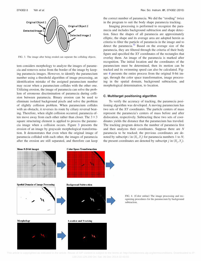
tem considers morphology to analyze the images of parame-cia and removes noise from the border of the image by keep-ing paramecia images. However, to identify the parameciumnumber using a threshold algorithm of image processing, anidentification mistake of the assigned paramecium numbermay occur when a paramecium collides with the other one.Utilizing erosion, the image of paramecia can solve the prob-lem of erroneous discrimination of paramecia during colli-sion between paramecia. Binary erosion can be used toeliminate isolated background pixels and solve the problemof slightly collision problem. When paramecium collideswith an obstacle, it reverses its route by ciliary reversal beat-ing. Therefore, when slight collision occurred, paramecia of-ten move away from each other rather than closer. The 3�3square structuring element is applied to process the parame-cia image when a collision occurs. Figure 3 presents theerosion of an image by grayscale morphological transforma-tion. It demonstrates that even when the original image ofparamecia collided with each other, the images of parameciaafter the erosion are still separated, and therefore can keep
the correct number of paramecia. We did the “eroding” twicein the program to suit the body shape paramecia tracking.
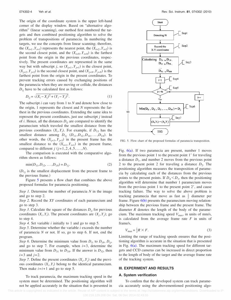
Imaging processing is performed to recognize the para-mecia and includes background subtraction and shape detec-tion. Since the shapes of all paramecia are approximatelyelliptic, the shape and its average area are adopted herein ascriteria to filter the particle of paramecia in the image and todetect the paramecia.32 Based on the average size of theparamecia, they are filtered through the criteria of their bodyfigure and specified the XY coordinates of the rectangles thatoverlay them. An image of the paramecia is marked afterrecognition. The initial location and the coordinates of theparamecium must be determined, then its motion can betracked and its swimming speed can also be calculated. Fig-ure 4 presents the entire process from the original 8-bit im-age, through the color space transformation, image process-ing in the spatial domain, background subtraction, andmorphological determination, to location.
C. Multitarget positioning algorithm
To verify the accuracy of tracking, the paramecia posi-tioning algorithm was developed. A moving paramecium hastwo sets of the XY coordinates. The particle centers of massrepresent the paramecia’s centers of mass before and afterdislocation, respectively. Subtracting these two sets of coor-dinates yields the distance that the paramecium has traveled.The tracking program detects the number of paramecia firstand then analyzes their coordinates. Suppose there are Nparamecia to be tracked; the previous coordinates are de-noted by subscript i in �Xi ,Yi� for paramecia numbers 1 to N;the present coordinates are denoted by subscript j in �Xj ,Y j�.
FIG. 3. The image after being eroded can separate the colliding objects.
FIG. 4. �Color online� The image processing and rec-ognizing procedures for the paramecium by backgroundsubtraction.
074302-3 Yeh et al. Rev. Sci. Instrum. 81, 074302 �2010�
This article is copyrighted as indicated in the article. Reuse of AIP content is subject to the terms at: http://scitationnew.aip.org/termsconditions. Downloaded to IP:
130.216.129.208 On: Sat, 06 Dec 2014 02:43:55
The origin of the coordinate system is the upper left-handcorner of the display window. Based on “alternative algo-rithm” �linear scanning�, our method first numbered the tar-gets and then combined positioning algorithm to solve theproblem of transpositions of paramecia. In numbering thetargets, we use the concepts from linear scanning; therefore,the �Xi=1 ,Yi=1� represents the nearest point, the �Xi=2 ,Yi=2� isthe second closest point, and the �Xi=N ,Yi=N� is the farthestpoint from the origin in the previous coordinates, respec-tively. The present coordinates are represented in the sameway but with subscript j, so �Xj=1 ,Y j=1� is the closest point,�Xj=2 ,Y j=2� is the second closest point, and �Xj=N ,Y j=N� is thefarthest point from the origin in the present coordinates. Toprevent tracking errors caused by exchanging positions ofthe paramecia when they are moving or collide, the distancesDij have to be calculated first as follows:
Dij = ��Xi − Xj�2 + �Yi − Y j�2. �1�
The subscript i can vary from 1 to N and denote how close tothe origin, 1 represents the closest and N represents the far-thest in the previous coordinates. Extending the same idea torepresent the present coordinates, just use subscript j insteadof i. Hence, all the distances Dij are compared to identify theparamecium which traveled the smallest distance from theprevious coordinates �Xi ,Yi�. For example, if D13 has thesmallest distance among D1j �D11,D12,D14, . . . ,D1N�. Inother words, the �Xj=3 ,Y j=3� in the present frame has thesmallest distance to the �Xi=1 ,Yi=1� in the present frame,compared to different j �j=1,2 ,4 ,5 , . . . ,N�.
The comparison is executed with the comparative algo-rithm shown as follows:
min�D11,D12, . . . ,D1N� = D1j . �2�
�D1j is the smallest displacement from the present frame tothe previous frame.�
Figure 5 presents a flow chart that combines the aboveproposed formulas for paramecia positioning.
Step 1. Determine the number of paramecia N in the imageand go to step 2.Step 2. Record the XY coordinates of each paramecium andgo to step 3.Step 3. Calculate the square of the distances Dij for previouscoordinates �Xi ,Yi�. The present coordinates are �Xj ,Y j�; goto step 4.Step 4. Set variable i initially to 1 and go to step 5.Step 5. Determine whether the variable i exceeds the numberof paramecia N or not. If so, go to step 6. If not, end theprogram.Step 6. Determine the minimum value from Di1 to DiN, Dij,and go to step 7. For example, when i=3, determine theminimum value from D31 to D3N. If the answer is D32, theni=3 and j=2.Step 7. Define the present coordinates �Xj ,Y j� and the previ-ous coordinates �Xi ,Yi� belong to the identical paramecium.Then make i= i+1 and go to step 5.
To track paramecia, the maximum tracking speed in thesystem must be determined. The positioning algorithm willnot be applied accurately in the situation that is presented in
Fig. 6�a�. If two paramecia are present, number 1 movesfrom the previous point 1 to the present point 1� for travelinga distance D1, and number 2 moves from the previous point2 to the present point 2 for traveling a distance D2. Thepositioning algorithm measures the transposition of parame-cia by calculating each of the distances from the previouspoints to the present points. If DA�D1, then the positioningalgorithm will determine that number 1 paramecium movesfrom the previous point 1 to the present point 2�, and causetracking failure. The way to solve the above problem istracking paramecia that move as fast as 1
2 diameter perframe. Figure 6�b� presents the paramecium moving relation-ship between the previous frame and the present frame. Thediameter R denotes the length of the body of the parame-cium. The maximum tracking speed Vmax, in units of mm/s,is calculated from the average frame rate F in units offrame/s,
Vmax = 12R � F . �3�
Limiting the range of tracking speeds ensures that the posi-tioning algorithm is accurate in the situation that is presentedin Fig. 6�a�. The maximum tracking speed for different tar-gets and CCD cameras can be increased in direct proportionto the length of body of the target and the average frame rateof the tracking system.
III. EXPERIMENT AND RESULTS
A. System verification
To confirm that the developed system can track parame-cia accurately using the abovementioned positioning algo-
FIG. 5. Flow chart of the proposed formulas of paramecia transposition.
074302-4 Yeh et al. Rev. Sci. Instrum. 81, 074302 �2010�
This article is copyrighted as indicated in the article. Reuse of AIP content is subject to the terms at: http://scitationnew.aip.org/termsconditions. Downloaded to IP:
130.216.129.208 On: Sat, 06 Dec 2014 02:43:55

rithm, Macromedia Flash �Adobe Systems, Inc., USA� wasadopted to simulate the shape, direction, trajectory, andspeed of a moving paramecium. Each frame with 1000�1000 pixels was designed to cover the image of a circularexperimental pool with 4 mm diamater on the slide. Becausethe shape of paramecium is approximately elliptic, the simu-lated targets for tracking were designed to be elliptic with asize of 46�length��14�width� pixels. Since both the lengthand the width of a pixel in the system are 0.0043 mm, thebody-length of the simulated targets for tracking is approxi-mately 0.2 mm �200 �m�, within a range from 100 to200 �m presented before.17 These simulated targets aretracked to verify the effectiveness of the algorithm designedby the following three procedures.
1. Positioning algorithm verification
�1� First, the coordinates detected by the tracking systemmust be confirmed. An AVI image is designed with aframe rate of 17 frames/s in 6 min and the position of asimulated target is assigned for each frame. The targetbegins from �50, 50� and moves 20 pixels along a squareroute in each frame until it has traveled 612 000 pixels.In this event, the determined average error in the XYcoordinates is 0 pixel, and the mean absolute percentageerror in the displacement per frame is 0.
�2� The moving targets were designed to follow a counter-clockwise route. Three simulated targets are designedsquare, circular, and triangular routes, respectively. Theinitial coordinates of the targets before they move alongthe square, circle, and triangle routes are �74, 62�, �552,914�, and �907, 909�, respectively. The targets are de-tected by linear scanning, which sets the number of tar-gets according to the distance along the Y-axis of a tar-get to the origin and then the distance along the X-axisfrom the target to the origin. The target that moves alonga square route is target 1. The target that moves along acircular route is target 2, and the target that moves alonga triangular route is target 3. Figure 7�a� presents the lociof the targets obtained by the tracking system withoutthe paramecia positioning algorithm. The program as-signs numbers of paramecia to the tracking system fromthe distance first along the Y-axis and second along theX-axis from the target to the origin. After the targets arenumbered by linear scanning, we compare Fig. 7�b�,which did not use positioning algorithm, and Fig. 7�c�,which used positioning algorithm. Figure 7�b� presentsthe resulting with the alternative algorithm but the posi-tioning algorithm. In Fig. 7�b�, track 1 �the left picture�is the route of target 1 at nearest point to the origin, track2 �the middle picture� is that of target 2, which is at thesecond-nearest point to the origin, and track 3 �the rightpicture� is that of target 3, which is at the farthest point.Figure 7�c� presents the loci of the targets obtained bytracking system with the alternative algorithm and theparamecia positioning algorithm. The tracks in track 1,
FIG. 6. �a� The orbits of two paramecia from 1 to 1� and from 2 to 2�. Thepositioning algorithm will be fault when DA�D1, and will judge the para-mecium 2� as the present target from the early target paramecium 1. �b� Therelationship between the early frame and the present frame of the target.
FIG. 7. �Color online� The experiment of tracking paramecia with transpo-sition gauging: �a� A paramecium is simulated to move along a square path,a circular path, and a triangle path as shown in the left picture, the middlepicture, and the right picture, respectively. �b� When using the trackingprogram without positioning algorithm, it drew the wrong loci. �c� Using thetracking program to draw the loci for verifying the positioning algorithmwith multitargets in a simple transposition situation.
074302-5 Yeh et al. Rev. Sci. Instrum. 81, 074302 �2010�
This article is copyrighted as indicated in the article. Reuse of AIP content is subject to the terms at: http://scitationnew.aip.org/termsconditions. Downloaded to IP:
130.216.129.208 On: Sat, 06 Dec 2014 02:43:55
track 2, and track 3 yield the tracking accuracy alongsquare, circular, and triangular routes, respectively. Therelated experiment is designed to determine the effec-tiveness of the program in the transposition of targets.
2. Image processing for collision verification
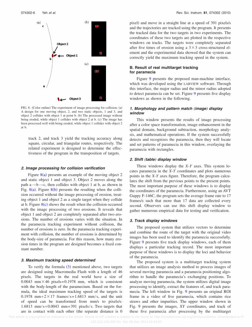
Figure 8�a� presents an example of the moving object 2and static object 1 and object 3. Object 2 moves along thepath a→b→c, then collides with object 1 at b, as shown inFig. 8�a�. Figure 8�b� presents the resulting when the colli-sion occurred without the image processing of erosion, treat-ing object 1 and object 2 as a single target when they collideat b. Figure 8�c� shows the result when the collision occurredwith the image processing of two erosions. It reveals thatobject 1 and object 2 are completely separated after two ero-sions. The number of erosions varies with the situation. Inthe paramecia tracking experiment without collision, thenumber of erosions is zero. In the paramecia tracking experi-ment with collision, the number of erosions is determined bythe body-size of paramecia. For this reason, how many ero-sion times in the program are designed becomes a fixed con-stant number.
3. Maximum tracking speed determined
To verify the formula �3� mentioned above, two targetsare designed using Macromedia Flash with a length of 46pixels. The targets in the real world have a size of0.0043 mm�46 pixels=0.1978 mm, which is consistentwith the body-length of the paramecium. Based on the for-mula, the ideal maximum tracking speed of the targets is0.1978 mm÷2�17 frames /s=1.6813 mm /s, and the unitof speed can be transformed from mm/s to pixels/s:1.6813 mm /s÷0.0043 mm=391 pixels /s. Two targets thatare in contact with each other �the separate distance is 0
pixel� and move in a straight line at a speed of 391 pixels/sand the trajectories are tracked using the program. It presentsthe tracked data for the two targets in two experiments. Thecoordinates of these two targets are plotted in the respectivewindows on tracks. The targets were completely separatedafter five times of erosion using a 3�3 cross-structured el-ement and the experimental data showed that the system cancorrectly yield the maximum tracking speed in the system.
B. Result of real multitarget trackingfor paramecia
Figure 9 presents the proposed man-machine interface,which was developed using the LABVIEW software. Throughthis interface, the major radius and the minor radius adoptedto detect paramecia can be set. Figure 9 presents five displaywindows as shown in the following.
1. Morphology and pattern match „image… displaywindow
This window presents the results of image processingafter a color space transformation, image enhancement in thespatial domain, background subtraction, morphology analy-sis, and mathematical operations. If the system successfullydetects and recognizes the paramecia, then they will locateand set patterns of paramecia in this window, overlaying theparamecia with rectangles.
2. Shift „table… display window
These windows display the X-Y axes. This system lo-cates paramecia in the X-Y coordinates and plots numerouspoints in the X-Y axes figure. Therefore, the program calcu-lates the shift from the previous points to the present points.The most important purpose of these windows is to displaythe coordinates of the paramecia. Furthermore, using an AVTGuppy F-146C, the program sets the average frame rate to 17frames/s such that more than 17 data are collected everysecond. Observers can use this shift display window togather numerous empirical data for testing and verification.
3. Track display windows
The proposed system that utilizes vectors to determineand combine the route of the target with the original videoimages has been used to identify the paramecia successfully.Figure 9 presents five track display windows, each of themdisplays a particular tracking record. The most importantpurpose of these windows is to display the loci and behaviorof the paramecia.
The proposed system is a multitarget tracking systemthat utilizes an image analysis method to process images ofseveral moving paramecia and a paramecia positioning algo-rithm to handle the paramecia’s exchanging positions. Toanalyze moving paramecia, the system utilizes digital imageprocessing to identify, extract the features of, and track para-mecia. The left window in Fig. 9 presents an original ROIframe in a video of five paramecia, which contains ricestraws and other impurities. The upper window shown inFig. 9 presents the images, XY coordinates, and track ofthese five paramecia after processing by the multitarget
FIG. 8. �Color online� The experiment of image processing for collision. �a�A design for one moving object, 2, and two static objects, 1 and 3, andobject 2 collides with object 1 at point b. �b� The processed image withoutbeing eroded, while object 1 collides with object 2 at b. �c� The image hasbeen processed well with being eroded, while object 1 collides with object 2at b.
074302-6 Yeh et al. Rev. Sci. Instrum. 81, 074302 �2010�
This article is copyrighted as indicated in the article. Reuse of AIP content is subject to the terms at: http://scitationnew.aip.org/termsconditions. Downloaded to IP:
130.216.129.208 On: Sat, 06 Dec 2014 02:43:55

tracking system. The right-hand window in Fig. 9 presentsthe processed image of five paramecia in the morphologyand pattern match display window. The paramecia are as-signed numbers from 1 to 5 by an image processing programthat displays the tracked orbits in track 1 to track 5 windows,respectively. The average frame rate obtained by the process-ing of the image of five paramecia is 4.6 frames/s.
IV. DISCUSSION
Based on the results of the aforementioned experiments,we can find that the maximum tracking speed of a multitargettracking system for normal paramecia tracking may be cal-culated from the average frame rate to be 1.7 mm/s �that is,100 �m�17 frames /s=1700 �m /s=1.7 mm /s using for-mula �3��, which is limited by the system. However, whenthe paramecia are stimulated, they can swim as fast as10–20 diameter /s4, and if the body-length of a parameciumis 200 �m, then its maximum swimming speed is 200 �m�20 diameters /s=4 mm /s, such that the frame rate of thecamera must be 4 mm /s÷100 �m=40 frames /s. Somebacteria can swim as fast as 50 diameter/s,17,33 and so theframe rate of the camera must be 100 frames/s. In this study,the CCD camera, AVT Guppy F-146C, is used to track theparamecia. However, it can be replaced if a greater maxi-mum tracking speed is required for the other measurementsof reaction behavior. Even if the image-capturing device ischanged, the method of image analysis and the parameciapositioning algorithm in this tracking system are still useful.
The XY coordinates detected in the tracking system areverified by the simulated tracking target with a length of200 �m designed in Macromedia Flash. This experimentalresult demonstrates that the detected average error in the XYcoordinates is zero, meaning that the multitarget trackingsystem is entirely accurate in detecting coordinates. Al-though experiment for verifying the positioning algorithm isdesigned in an ideal condition with noise-free, but the imageprocessing of ROI can be used to filter out the unwantedimage and the binary erosion can be used to eliminate iso-lated background pixels. Also the accuracy of this multipara-mecium tracking still can be maintained on condition thatparamecium does not swim into an obstacle. However, if theimage is covered by other objects, for example, rice straws,mosses, or process failed, the coordinates of the midpointsdetected from an incomplete paramecia image reveal that theparamecia tracking is inaccurate.
The proposed paramecia tracking system provides asimple but useful method. It includes the following contribu-tions: first, at the present time, there are no microscope con-cave slides, which have 4 mm diameter cavity in the market.The paramecia experimental pool is circular-shaped with adiameter of 4 mm and made by puncher and cutting sheet,which can make our own microscope slides and the slidescan monitor paramecia moving in full view. The testing pool,which must be made as thin as possible in that experiment,can be achieved without interfering with the paramecia’sswimming.4 A deeper observational pool cannot only cause
FIG. 9. �Color online� The processed image with coordinates and trajectories of five paramecia in the morphology and pattern match display window. The leftwindow is an original ROI frame in the video image of five paramecia with impurities.
074302-7 Yeh et al. Rev. Sci. Instrum. 81, 074302 �2010�
This article is copyrighted as indicated in the article. Reuse of AIP content is subject to the terms at: http://scitationnew.aip.org/termsconditions. Downloaded to IP:
130.216.129.208 On: Sat, 06 Dec 2014 02:43:55

the image of the paramecia to be out of focus but also allowthe paramecia to swim above or under each one, causing anerror in collision detection. Second, this system uses imageprocessing and positioning algorithm to track multitargetswithout any dye. Therefore, the negative effects of dye canbe eliminated. In the past researches, even if there were morethan one paramecium in the dish, only one paramecium canbe tracked. This multitarget tracking system solved this prob-lem and thus save time and labor. Third, it is simple andinexpensive; almost everyone can easily perform the experi-ment. Fourth, without “image processing,” it will be difficultto recognize paramecia in the situations such as complexbackground or slightly collision. Without “positioning algo-rithm,” there will be errors initially close to the origin andthen moves away, whereas another cell starts far off and thenmoves toward the origin.
This study utilizes the LABVIEW software to implementthe proposed tracking algorithm. Moreover, the tracking ofthe paramecia depends on their swimming orbit and coordi-nates. The proposed computerized video tracking system notonly can save significant time and manpower for the re-searchers, while still produces optimal results, but alsogather numerous meaningful data simultaneously. Experi-mental results reveal the effectiveness of the multitargettracking system, which maintains tracking even when trans-posed or slight collision occurred. In the future, methods forprocessing paramecia images covered by obstacles, whichwill include optical flow method as well as an algorithm forautomatically adjusting the number of eroding time to suitdifferent body shapes and sizes for microorganisms trackingshall be developed.
ACKNOWLEDGMENTS
The authors would like to thank the National ScienceCouncil and I-Shou University of Taiwan, Republic ofChina, for their financial supports under Contract Nos.NSC96-2221-E-006-234-MY3 and ISU98-01-07.
1 N. Ogawa, H. Oku, K. Hashimoto, and M. Ishikawa, Proceedings of the2004 IEEE International Symposium on Biomedical Imaging �IEEE, Ar-lington, 2004�, Vol. 2, pp. 1331–1334.
2 N. Ogawa, H. Oku, K. Hashimoto, and M. Ishikawa, J. Theor. Biol. 242,314 �2006�.
3 I. Akitoshi and T. Hideki, Proceedings of the 2001 IEEE/ASME Interna-tional Conference on Advanced Intelligent Mechatronics �IEEE, Como,2001�, Vol. 2, pp. 1220–1225.
4 I. Akitoshi, IEEE/ASME Trans. Mechatron. 5, 181 �2000�.5 N. Ogawa, H. Oku, K. Hashimoto, and M. Ishikawa, IEEE Trans. Rob.Autom. 21, 704 �2005�.
6 N. Ogawa, H. Oku, K. Hashimoto, and M. Ishikawa, Proceedings of the2004 IEEE International Conference on Robotics and Automation �IEEE,New Orleans, 2004�, Vol. 2, pp. 1646–1651.
7 N. Ogawa, H. Oku, K. Hashimoto, and M. Ishikawa, Proceedings of the2005 IEEE International Conference on Robotics and Automation �IEEE,Barcelona, 2005�, pp. 1246–1251.
8 H. Machemer, Adv. Space Res. 21, 1301 �1998�.9 A. Hirano, T. Tsuji, N. Takiguchi, and H. Ohtake, Proceedings of the 2006IEEE International Conference on Man and Cybernetics �IEEE, Taipei,2006�, Vol. 5, pp. 3612–3617.
10 T. Takahashi, M. Yoshii, T. Kawano, T. Kosaka, and H. Hosoya, Toxicol.In Vitro 19, 99 �2005�.
11 K. Kawamoto, Y. Nishikawa, K. Oami, Y. Jin, I. Sato, N. Saito, and S.Tsuda, J. Toxicol. Sci. 33, 155 �2008�.
12 J. Bernal and S. Ruvalcaba, Toxicology 108, 165 �1996�.13 P. Madoni, Environ. Pollut. 109, 53 �2000�.14 J. Venkateswara Rao, K. Srikanth, S. K. Arepalli, and V. G. Gunda, Pestic.
Biochem. Physiol. 86, 131 �2006�.15 J. Venkateswara Rao, V. G. Gunda, K. Srikanth, and S. K. Arepalli, Toxi-
col. Environ. Chem. 89, 307 �2007�.16 J. Venkateswara Rao, S. K. Arepalli, V. G. Gunda, and J. Bharat Kumar,
Pestic. Biochem. Physiol. 91, 75 �2008�.17 H. Oku, N. Ogawa, M. Ishikawa, and K. Hashimoto, Rev. Sci. Instrum.
76, 034301 �2005�.18 X. Fei, Y. Igarashi, and K. Hashimoto, Proceedings of the 2008 IEEE/
ASME International Conference on Advanced Intelligent Mechatronics�IEEE, Xi’an, 2008�, pp. 752–757.
19 H. Oku, I. Ishii, and M. Ishikawa, Proceedings of the 2000 First AnnualInternational Conference on Microtechnologies in Medicine and Biology�IEEE, Lyon, 2000�, pp. 156–159.
20 B. Taboada, S. Poggio, L. Camarena, and G. Corkidi, Proceedings of the2003 25th Annual International Conference of the IEEE on Engineering inMedicine and Biology Society �IEEE, Albuquerque, 2003�, Vol. 1, pp.906–909.
21 Y. J. Chen, Y. C. Li, K. N. Huang, S. L. Jen, and M. S. Young, Instrum.Sci. Technol. 37, 366 �2009�.
22 Y. J. Chen, Y. C. Li, K. N. Huang, S. L. Jen, and M. S. Young, Rev. Sci.Instrum. 79, 085108 �2008�.
23 W. Niblack, An Introduction to Digital Image Processing �Prentice-Hall,Englewood Cliffs, NJ, 1986�, pp. 115–116.
24 S. Mukhopadhyay and B. Chanda, Signal Process. 82, 527 �2002�.25 R. M. Haralick, S. R. Sternberg, and X. Zhuang, IEEE Trans. Pattern Anal.
Mach. Intell. PAMI-9, 532 �1987�.26 B. M. Mehtre, Mach. Vision Appl. 6, 124 �1993�.27 A. Almansa and T. Lindeberg, IEEE Trans. Image Process. 9, 2027
�2000�.28 A. Toprak and İ. Güler, Digit. Signal Process. 17, 711 �2007�.29 J. Park, A. Tabb, and A. C. Kak, Proceedings of the 2006 IEEE Interna-
tional Conference on Image Processing �IEEE, Atlanta, 2006�, pp. 1849–1852.
30 E. Zhang, F. Chen, and W. Zhang, Proceedings of the 2006 InternationalConference on Computational Intelligence and Security �IEEE, Beijing,2008�, Vol. 2, pp. 1837–1840.
31 L. Jia and Y. Liu, Proceedings of the 2008 IEEE Workshop on Applica-tions of Computer Vision �IEEE, Colorado, 2008�, pp. 1–6.
32 M. Stanojevic, S. Vranes, and D. Velasevic, Proceedings of the 1996 29thHawaii International Conference on System Sciences �IEEE, Wailea,2008�, Vol. 2, pp. 201–209.
33 H. C. Berg, Rev. Sci. Instrum. 42, 868 �1971�.
074302-8 Yeh et al. Rev. Sci. Instrum. 81, 074302 �2010�
This article is copyrighted as indicated in the article. Reuse of AIP content is subject to the terms at: http://scitationnew.aip.org/termsconditions. Downloaded to IP:
130.216.129.208 On: Sat, 06 Dec 2014 02:43:55