development of 16 μm continuous-wave modulation hard-target differential absorption lidar system...
TRANSCRIPT

May 15, 2009 / Vol. 34, No. 10 / OPTICS LETTERS 1513
Development of 1.6 �m continuous-wavemodulation hard-target differential absorption
lidar system for CO2 sensing
Shumpei Kameyama,1,* Masaharu Imaki,1 Yoshihito Hirano,1 Shinichi Ueno,2 Shuji Kawakami,3
Daisuke Sakaizawa,3 and Masakatsu Nakajima4
1Information Technology R&D Center, Mitsubishi Electric Corporation, Japan2Kamakura Works, Mitsubishi Electric Corporation, Japan
3Earth Observation Research Center, Japan Aerospace Exploration Agency, Japan4Greenhouse Gases Observing Satellite (GOSAT) Project Team, Japan Aerospace Exploration Agency, Japan
*Corresponding author: [email protected]
Received February 2, 2009; revised March 28, 2009; accepted April 1, 2009;posted April 2, 2009 (Doc. ID 107021); published May 7, 2009
We have demonstrated the 1.6 �m cw modulation hard-target differential absorption lidar system for CO2sensing. In this system, ON and OFF wavelength laser lights are intensity modulated with cw signals. Re-ceived lights of the two wavelengths from the hard target are discriminated by modulation frequencies inthe electrical signal domain. The optical circuit is fiber based, and this makes the system compact and re-liable. It is shown that a stable CO2 concentration measurement corresponding to a fluctuation of 4 ppm(rms) (ppm is parts per million) has been achieved in 32 s measurement intervals and the 1 km path.© 2009 Optical Society of America
OCIS codes: 010.3640, 280.3640.
For the application to global CO2 sensing from thesatellite, differential absorption lidar (DIAL) systemsusing the conventional coherent and incoherent lidarmethods have been studied [1–5]. However, to ourknowledge the conclusion about the best system con-figuration has not been determined yet because of thesevere requirements for the satellite-borne sensor aswell as the precise measurements that are needed. Asthe result of our consideration to overcome this issue,we invented the cw modulation hard-target DIALsystem [6], which has the features in the simulta-neous transmission of two wavelengths and the dis-crimination of the wavelength in the electrical signaldomain. In this Letter, we demonstrate this DIALsystem for ground-based CO2 sensing using thewavelength of 1.6 �m.
The system configuration is shown in Fig. 1. Themain system parameters are listed in Table 1. The cwlaser lights of 1.6 �m wavelength range are locked atthe ON and OFF wavelengths and intensity modu-lated with cw signals. The frequencies of the twomodulation signals are slightly different from eachother. The modulations with different frequencies arefor discrimination of ON and OFF components afterreceiving. The modulated lights are amplified by theerbium-doped fiber amplifier after being combinedwith an optical coupler. The amplified light is tappedby the tap coupler. The light from the 99% port istransmitted to a hard target both simultaneously andcoaxially. The light from the 1% port is detected asthe monitored signal by the photodetector for trans-mission monitoring. All optical fibers used in thetransmitting and monitoring lines are the singlemode or the polarization maintained type. The back-scattered light is received by the telescope, coupled tothe multimode optical fiber, and detected as the re-ceived signal by the photodetector. The monitored
and the received signals are analog-to-digital (A–D)0146-9592/09/101513-3/$15.00 ©
converted and processed in the personal-computer(PC)-based signal processor. In the signal processing,the spectra of the monitored and the received signalsare obtained using the fast Fourier transform, andthe peaks corresponding to the two wavelengths ap-pear at the modulation frequencies in each spectrum.The intensities of the two peaks in the spectrum ofthe received signal are normalized by those of themonitored signal. The differential optical depth is ob-tained using the ratio of the normalized detected in-tensities of the two wavelengths. The ranging of thetarget is possible by utilizing the phase difference be-tween the monitored and the received signals. Sincecw signals are used for this ranging, there is a foldingambiguity. A priori information on the range solvesthis problem if this information has the precision of�c / �2fm� [c: speed of light (m/s) and fm: modulationfrequency (Hz)]. In our opinion, this precision can beeasily obtained in both ground-based and space-borne measurements if the modulation frequency islower than or equal to the 100 kHz band. The path-averaged CO2 concentration can be obtained from thedifferential optical depth, the target range, and theparameters of the absorption line, which are used inthe ON wavelength.
Fig. 1. System configuration of the 1.6 �m cw modulation
hard-target DIAL system.2009 Optical Society of America
1514 OPTICS LETTERS / Vol. 34, No. 10 / May 15, 2009
The system is eye safe by using the wavelength re-gion of 1.6 �m. A stable performance can be realizedeven in severe environmental conditions, since ma-ture fiber-based components are used in the system.In addition, this fiber-based configuration easily real-izes the simultaneous transmission of the two wave-lengths from the same optical fiber. This feature per-fectly identifies the sensing volume and the footprintof the two wavelengths and becomes an advantagefor the precise measurement especially in the mea-surement from the moving satellite. Furthermore,the discrimination of the wavelengths works verystably, since this can be done in the electrical signaldomain. The optical detection sensitivity can be veryhigh by using base-band (i.e., low) modulation fre-quencies.
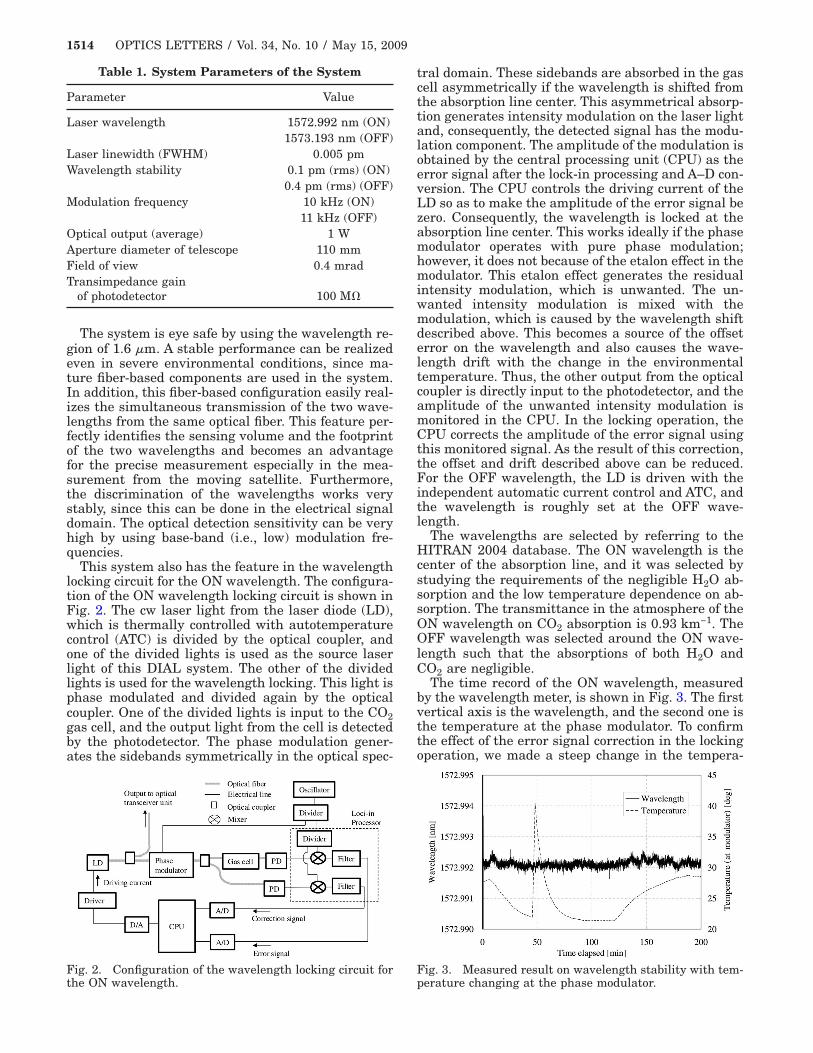
This system also has the feature in the wavelengthlocking circuit for the ON wavelength. The configura-tion of the ON wavelength locking circuit is shown inFig. 2. The cw laser light from the laser diode (LD),which is thermally controlled with autotemperaturecontrol (ATC) is divided by the optical coupler, andone of the divided lights is used as the source laserlight of this DIAL system. The other of the dividedlights is used for the wavelength locking. This light isphase modulated and divided again by the opticalcoupler. One of the divided lights is input to the CO2gas cell, and the output light from the cell is detectedby the photodetector. The phase modulation gener-ates the sidebands symmetrically in the optical spec-
Table 1. System Parameters of the System
Parameter Value
Laser wavelength 1572.992 nm (ON)1573.193 nm (OFF)
Laser linewidth (FWHM) 0.005 pmWavelength stability 0.1 pm (rms) (ON)
0.4 pm (rms) (OFF)Modulation frequency 10 kHz (ON)
11 kHz (OFF)Optical output (average) 1 WAperture diameter of telescope 110 mmField of view 0.4 mradTransimpedance gain
of photodetector 100 M�
Fig. 2. Configuration of the wavelength locking circuit for
the ON wavelength.tral domain. These sidebands are absorbed in the gascell asymmetrically if the wavelength is shifted fromthe absorption line center. This asymmetrical absorp-tion generates intensity modulation on the laser lightand, consequently, the detected signal has the modu-lation component. The amplitude of the modulation isobtained by the central processing unit (CPU) as theerror signal after the lock-in processing and A–D con-version. The CPU controls the driving current of theLD so as to make the amplitude of the error signal bezero. Consequently, the wavelength is locked at theabsorption line center. This works ideally if the phasemodulator operates with pure phase modulation;however, it does not because of the etalon effect in themodulator. This etalon effect generates the residualintensity modulation, which is unwanted. The un-wanted intensity modulation is mixed with themodulation, which is caused by the wavelength shiftdescribed above. This becomes a source of the offseterror on the wavelength and also causes the wave-length drift with the change in the environmentaltemperature. Thus, the other output from the opticalcoupler is directly input to the photodetector, and theamplitude of the unwanted intensity modulation ismonitored in the CPU. In the locking operation, theCPU corrects the amplitude of the error signal usingthis monitored signal. As the result of this correction,the offset and drift described above can be reduced.For the OFF wavelength, the LD is driven with theindependent automatic current control and ATC, andthe wavelength is roughly set at the OFF wave-length.
The wavelengths are selected by referring to theHITRAN 2004 database. The ON wavelength is thecenter of the absorption line, and it was selected bystudying the requirements of the negligible H2O ab-sorption and the low temperature dependence on ab-sorption. The transmittance in the atmosphere of theON wavelength on CO2 absorption is 0.93 km−1. TheOFF wavelength was selected around the ON wave-length such that the absorptions of both H2O andCO2 are negligible.
The time record of the ON wavelength, measuredby the wavelength meter, is shown in Fig. 3. The firstvertical axis is the wavelength, and the second one isthe temperature at the phase modulator. To confirmthe effect of the error signal correction in the lockingoperation, we made a steep change in the tempera-
Fig. 3. Measured result on wavelength stability with tem-
perature changing at the phase modulator.
May 15, 2009 / Vol. 34, No. 10 / OPTICS LETTERS 1515
ture at the modulator locally with hot air flow in ad-dition to changing the room temperature. It is shownthat the stability of 0.1 pm (rms) including the re-sidual drift of wavelength is obtained. This stabilitycorresponds to 0.5% of the absorption linewidth (at 1atm and 296 K) and is 20 times larger than the laserlinewidth. The error of the estimated CO2 absorptioncoefficient caused by this stability is about 0.03% andnegligible even if the precision of 1 ppm (ppm is partsper million) is needed in the background of 400 ppm.The stability of the OFF wavelength, which is notshown here, is 0.4 pm (rms), and the influence of thisstability on the CO2 measurement is lower than0.001% and considered to be negligible.
Figure 4 shows the time record of the calibrationtest. In this test, the transmitting laser light is back-scattered by a diffuse hard target located in front ofthe optical antenna unit at a range of 0 m. The firstvertical axis shows the ratio of the normalized de-tected intensities of the two wavelengths, which ide-ally should be 0 dB since there is no CO2 absorption.The second axis shows the environmental tempera-ture, which was changed on purpose. The stability ofthe ratio is 0.006 dB (rms), which corresponds to theprecision of 2 ppm (rms) for a 1 km path even in theenvironmental temperature change.
The time record of CO2 concentration obtained bythis system at Kamakura City by assuming the totalair pressure of 1 atm and the temperature of 296 K isshown in Fig. 5. In the experiments, the target was atree located at the range of 980 m. The measurementinterval was 32 s. To confirm the validity of the mea-surement results roughly, we also measured CO2 con-centration by using the in situ CO2 sensor (ShibataScientific Technology Ltd., COX-2). In this experi-ment, we could not confirm the measurement accu-racy of the order of 1 ppm, since we used some as-sumptions on the atmospheric conditions in the DIALmeasurement as we described above and, further-more, the nominal specification of the accuracy of thein situ sensor was 50 ppm, although we were sure
Fig. 4. Result of the calibration test with environmentaltemperature changing.
that the actual specification was much better. How-ever, it is shown that stable measurements withshort time fluctuations corresponding to 4 ppm (rms)were obtained with a 32 s measurement interval.Furthermore, there is qualitative good agreementwith, at least, the diurnal changes between the re-sults of the DIAL system and the in situ CO2 sensor.
In conclusion, we reported the development of the1.6 �m fiber-based cw modulation hard-target DIALsystem for CO2 sensing. Through the ground-basedCO2 sensing, we have demonstrated the stable mea-surement with short time fluctuations correspondingto the concentration of 4 ppm (rms) in a 32 s intervaland 1 km path. Although the system is a develop-ment step and more research is necessary, the con-figuration of this system is suitable for the satellite-borne sensor. The development of the keycomponents, including the high-power optical ampli-fier, the large aperture optical antenna, and a moreprecise wavelength locking circuit, is needed in thefuture to realize a more precise and longer-path mea-surement from the satellite.
References
1. R. M. Menzies and D. M. Tratt, Appl. Opt. 42, 6569(2003).
2. G. J. Koch, B. W. Barns, M. Petros, J. Y. Beyon, F.Amzajerdian, J. Yu, R. E. Davis, S. Ismail, S. Vay, M. J.Kavaya, and U. N. Singh, Appl. Opt. 43, 5092 (2004).
3. G. J. Koch, J. Y. Beyon, F. Gibert, B. W. Barnes, S.Ismail, M. Petros, P. J. Petzar, J. Yu, E. A. Modlin, K.J. Davis, and U. N. Singh, Appl. Opt. 47, 944 (2008).
4. P. H. Flamant, in Proceedings of the InternationalLaser Radar Conference (2006), p. 347.
5. A. Amediek, A. Fix, M. Wirth, and G. Ehret, inProceedings of the 23rd International Laser RadarConference (2006), p. 143.
6. S. Kameyama and Y. Hirano, “Differential absorptionlidar apparatus having multiplexed light signals withtwo wavelengths in a predetermined beam size andbeam shape,” U.S. patent 7,361,922 (April 22, 2008).
Fig. 5. Time record of CO2 concentration measured by theDIAL system and that measured by the in situ CO2 sensor.