determination of the gyromagnetic ratio … bound... · and the magnetic resonance damping...
TRANSCRIPT
by H. G. BELJERS 538.221
,
R 335 Philips' Res. Repts 13, 10.16, 1958
DETERMINATION OF THE GYROMAGNETIC RATIOAND THE MAGNETIC RESONANCE DAMPING
COEFFICIENT OF FERRITES
SummaryResonance experiments are described on polycrystalline ferritespheres in a microwave cavity with a linearly polarized magnetic field.Fundamental quantities, like the g-factor and the damping coefficient'of the ferrite, are derived from the measurements. The damping co-efficient can be calculated either from a linewidth measurement orfrom the maximum amount of absorption in the ferrite at resonance.For a few samples reasonably corresponding results by the twomethods are given.
RésuméL'article décrit des expériences de rësonance de sphères de ferritepolycristallines dans une cavitë à microondes avee un champmagnë-tique polarisé linéairement. Des valeurs fondamentales comme Iefacteur g et le coefficient d'amortissement de la ferrite ~ont tirëes desmesures. Le coefficient d'amortissement peut être calculë soit à partird'une mesure de la largeur de la ligne, soit de l'absorption maximumdans la ferrite au moment de Ia résonance. Dei! résultats correspon-dant raisonnahlement entre-eux, obtenus par les deux mëthodes, sontdonnés pour quelques échantillons. -
ZnsammenCassungBeschrieben werden Resonanzversu~he an polykristallinen Ferrit-kugeln in einèm Mikrowellen-Hohlraumresonator mit linear polari-siertem Magnetfeld. Basisgröllen wie g-Faktor und Dämpfungs-koeffizient des Ferrits werden aus den Messungen abgeleitet. DerDämpfungskoeffizient lässt sich entweder aus einer Messung derLinienbreite oder aus der maximalen Absorption im Ferrit beiResonanz berechnen. Für einige Proben liefern die beiden Metho-den übereinstimmende Resultate.
I. Introduetion
The elements of the permeability tensor of a magnetized ferrite material, have been measured by several experimenters 1) 2), applying resonancecavities with circularly polarized modes. Besides the magnetization M andthe magnetic field H the most important quantities involved are, first, theg-factor, which deter:nines the gyromagnetic ratio y as given by the expres-sion Y= flog eJ2m, and secondly, a phenomenological damping term, e.g.,a relaxation time T introduced by Bloch 3).If we consider the equation of motion with such a damping term as an
approximation valid in 'a proper frequency range near ferromagnetic
GYROMAGNETIC RATIO AND MAGNETIC RESONANCE OF FERRITES 11
,Iresonance, the complex elements f1- and a of the permeability tensor can beexpressed in the basic quantities M, g, T ánd the magnetic field H.Às we shall see a measurement in a cavity with a linearly polarized micro-
wave field is sufficient to determine g and T; T can be determined from alinewidth measurment as well as from the maximum absorption in a cavityat resonance if the dimensions and saturation magnetization of the ferritesphere are given.
2. Magnetic resonance absorption measurements at 9400 Mc/s
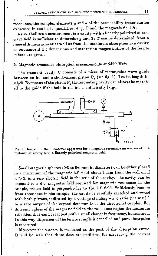
The resonant cavity C consists of a piece of rectangular wave guidebetween an iris and a short-circuit piston PI (see fig. I). Let its length benÀg/2. By means of the piston P 2 the resonating cavity can always be match-ed to the guide if the hole in the iris is sufficiently large.
Fig. 1.Diagram of the microwave apparatus for a magnetic resonance measurement in arectangular cavity with a linearly polarized magnetic field.
Small magnetic spheres (0·3 to 0·6 mm in diameter) can he either placedin a maximum of the magnetic h.f. field about 1 mm from the wall or, ifn ~ 2, in a zero electric field in the axis of the cavity. The cavity can heexposed to a d.c. magnetic field required for magnetic resonance in thesample, which field is pérpendicular to the h.f. field. Sufficiently' remotefrom resonance in the sample, the cavity is carefully matched and tunedwith both pistons, indicated by a voltage standing wave ratio (v.s.w.r.) 1or a zero output of the crystal detector D of the directional coupler. For
\ different values of the magnetic field in the resonance region the minimumreflection that can he reached, with a small change in frequency, is measured.In this way dispersion of the ferrite sample is cancelled and pure absorptionis measured. .
Moreover the v.s.w.r. is measured at the peak of the absorption curve.It will be seen th~t these data are sufficient for measuring the correct
_________ ~ ~ __~ _J
12 H. G. BELJERS
halfwidth value of the absorption curve. As we shall see in the next section,the halfwidth value of the measured curve r(H) depends on the ·loading ofthe cavity. .
3. CalcUlation of the influence of the cavity load on the bandwidth
.The normalized impedance of a cavity near resonance is given by 4)
I/Qez=· ,I/Qo + j(w/wa - wa/w)
(1),
where Qo is the quality factor of the unloaded cavity and Qe is a similarfactor accounting for the coupling to the guide. This quantity can beadjusted with the piston P2'
At the resonance of the cavity Z = Qo/Qe is made equal to 1 off magneticresonance. Resonance magnetic losses can be accounted for by a
Qm = G/X" (2)
and the resulting loaded Q, QL' is thus given by
Q-1·_Q-1 + Q-1L - 0 m- (3)
The reflection coefficient can be written as
r = (QL - QO)/(QL + Qo) .
Substituting (2) in (3) and (3) in (4) we find
(4)
x"r=-----X" + 2c/Qo
(5)
We conclude that the measured reflection at resonance for differentvalues of the magnetic field H is proportional to X" only if 2c/Qo is verylarge and thus, according to (2), if the cavity is very slightly loaded.Usually a correction is necessary to get the actual halfwidth value LlH.If we write
(6)
and 1] is the v.s.w.r. at resonance, we find
1] -1 1rm=----=----·
1]+1 l+p(7)
As the halfwidth points are defined by the relation X" = tX:;'nx we haver ( 1/(1 + 2p) and we derive the distance between the peak and the half-width value of the r(H) curve as
(9)
GYROllIAGNETIC RATIO AND lIIAGNETIC RESONANCE OF FERRITES 13
1 + 2p 17 + 3h = 20 log = 20 log -- dB. (8)
l+p 17+1
Thus the halfwidth value of the resonance curve r(IJ) should be measuredat a level h dB below the peak of the curve.
4. Susceptibility and damping coefficient for a ferrite rotational ellipsoid
We shall first give the expression for the' complex-valued quantities P-and a occurring in the permeability tensor according to the relation *)
Consider the Bloch relation with damping term
MM--H. H
M= y(MXH)---T--
For small values of the exciting field the term (M/H) H can be approx-imated by the projection of M on the z-axis Mz, and the equation can bewritten in the form
j(w' - jjT) (M - Mz) = y(MX H). (10)
The simplest way to account for the damping is to introduce a complexfrequency
t» = w' - jjT. (11)
If the Landau-Lifshitz 5) damping term {J is applied according to
• (JyM = y(M X H) - M M X (M X H) . (12)
then T should be substituted for 1/ (JyH.If He is the external magnetostatic field in the z-direction and hx, hy are
the h.f. components, Kittel's relations 6), resolved from (10) for mx and my,are
(13)
and
(14)
*) The time factor ejOJ' is understood throughout.
(15)
14 H. G. BELJERS
where Hr is given by the resonance condition
For a spherical sample (15) reduces to
COr = yHa. (16)
Thus the g-factor can be derived from the ratio of th~ resonance frequencyto the external magnetic field. _
In order to find the halfwidth value ofthe curve X"(H) we insert cor/y ±LlH/2 for Hr in (13). Since at the halfwidth points of the curve the real andimaginary points of the denominator are equal, subs,titution yields
Ty.LlH = 2. (17)
A general form for equation (17) valid for whatever shape of ferrite sample,provided that it is an ellipsoid or ean be approximated as such,. is
OCOr .-. T.LlH= 2.oH
(18)
We can conclude from (18) that in all cases where ocor/oH equals y (for e.g.,a sphere, a disk or a rod with the magnetizing field along the axis ofrotation) relation (21) is valid. The resonance relations for these shapes aregiven by co= yHa, CO = y(Ha + M) and co= y(H + M/2), respectively.It does not hold for the case of a disk with the magnetic field in its plane,
where we have the resonance condition co= yVHe(M + Ha).In order to determine the constant T in the second way we have to find
the relation between the maximum absorption in the cavity and thereflection coefficient.
Substitution of (ll) and (13) gives us the pure-imaginary susceptibility
(19)
if terms with T2 are neglected.Evaluating Qm in eq. (2) we have according to the standard meaning of
quality factor:c 2W
Qm = X" = X"h2L1v ' (20)
where W is the amount of oscillating energy in the.cavity, h is the value ofthe microwave' field at the place of the ferrite and Llv is the volume of theferrite sphere. From (6) we find
GYROMAGNETIC RATIO AND MAGNETIC RESONANCE OF 'FERRITES 15
2c 4WP = Qox" = Qox"h2LJv'
W is computed from the field components in the cavity of cross-sectionaldimensions a and b (a> b): '
(21)
, 2a six 2nzhx = ho - sin - cos --,
Ag a - Ag
nx 2nzhz = ho cos - sin -- ,
a Ag
a nx 2nzEy= wf-l-hosin- sin--.
n a Ag
Integration of E} over the cavity yields
(22)
where n is the number of half wavelengths in the cavity. Ifwe put h = shoand substitute (19) and (22) in (21) we find
T = 3na3bAg2nyMA2r3pQos2
(23)
In order to calculate Twe have to know in this case the total magnetization,which should be measured in the usual way.
The unloaded Qo can be measured if the v.s.w.r, is determined near theresonance frequency. 'I'hewidth ofthe curve 8·4,dB below the peak (v.s.w.r.= 1) gives us LJf = ffQo. This method has been described by, Slater 7). Thevalue of s depends on the situation ofthe ferrite in the cavity. ,We prefer toput the sample at the centre of the cavity at the end of a thin rod of poly-styrene half a wavelength from the piston. In that case s = 2af Ag.If the ferrite sphere is placed at a small distance d from the smaller wave-
guide wall s should be taken equal to cos (2ndf A).
5. Experimental results for a few ferrites
For a few polycrystalline ferrite spheres, made in the usua1 way 8), theg-factor is determined and the relaxation time T is calculated applyingrelations (17) and (23). Spheres of single crystals could also be measured ina preferred orientation.The table shows results of measurements for 3 spheres of ferrite and the
calculated values of the relaxation time TLJH derived from the bandwidthand Tabs derived from .maximum absorption.
3350 31.00 31.50 3500 Oersted
16 H. G. BELJERS
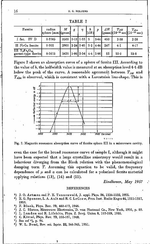
TABLE I
Ferrite radius M g 1'J h p LlH TLlH Tabesphere(mm) (gauss (dB (gauss (l0-10sec)(10-10 sec)
I fxc. IV D 0·3785 3500 2-12 1·55 5 3·64 450 2·38 2·28
II Ni-Cuferrite 0·302 2900 2·24 1·45 5·2 4-44 247 4··1 4·17III Y3Fe5012
0·2675 2·04 1·96garnet-type ferrite 1635 1-98 4·4 52 22·0 23·8
Figure 2 shows an absorption curve of a sphere of ferrite Hf, According tothe value of h, the halfwidth value is measured at an absorption level d-d dBbelow the peak of the curve. A reasonable agreement between TLlH andTabs is observed, whièh is consistent with a Lorentaian line-shape. This is
11:> 0.., -.~ -2E'-Cl>
:1;-aJ'-5~ -6'ai -7i~:-I-12
3300
I I \I \/ \. h
3/ \I. /JH
/ \/ \
0/ \/ \
0/ I'I/,
Fig. 2. Magnetic resonanceabsorption curve of ferrite sphere III in a microwavecavity.
even the case for the broad resonance curve of sample I, although it mighthave been expected that a large crystalline anisotropy would result in abehaviour diverging from the Bloch relation with the phenomenologicaldamping term T. Assuming this equation to be valid, the frequencydependence of f.L and a can be calculated for a polarized ferrite materialapplying relations (13), (14.) and (11).
Eindhoven, May 1957 .'REFERENCES
1) J. 0. Artman and P. E. Tannenwald, J. appl. Phys. 26, 1124-1132,1955.2) E. G. Spencer, L.A.Ault and R. C.LeCraw, Proc. Inst. Radio Engrs 44,1311-1317,
1956. .3) F. Bloèh, Phys. Rev. 70, 460-473,1946.4) J. C. Slater, MicrowaveElectronicsçD. van Nostrand Co., New York, 1950,p. 89.5) L. Landau and E. Lifshitz, Phys. Z. Sovj. Union 8, 153-169,1935. .6) C. Kittel, Phys. Rev. 73, 155-161,1948.7) See ref 4), p. 94.8) W. L. Bond, Rev. sci. Instr, 22, 344-345,1951.