determination of film thickness and refractive index by interferometry
TRANSCRIPT
� Applied Science Department,
Studies, P.O. Box 42325, Shuwai
+965-606-3819; fax: +965-481-0877.
E-mail address: hmshabana@hotm
0142-9418/$ - see front matter# 20
doi:10.1016/j.polymertesting.2004.01
College of Technological
kh 70654, Kuwait. Tel.:
ail.com (H.M. Shabana).
04 Elsevier Ltd. All rights reserved.
.006
Polymer Testing 23 (2004) 695–702
www.elsevier.com/locate/polytest
Test Method
Determination of film thickness and refractive indexby interferometry
H.M. Shabana �
Department of Physics, Faculty of Science, University of Mansoura, Mansoura 35516, Egypt
Received 8 December 2003; accepted 14 January 2004
Abstract
The interference fringes formed in an air wedge and those based on the theory of two-beam interference such asthe Pluta microscope and Michelson interferometer are utilized for estimating the thickness and/or refractive indexof transparent polypropylene thin films. The theories of the methods are presented, and their applications tomeasurement of film thickness and refractive index are given. The accuracy of the measured film thickness and refrac-tive index is calculated. The three interference methods proved that they could be transformed into valuable techno-logical tools. The study established that, estimation of the thickness of thin films by the air wedge interferencemethod is more simple and more accurate than the others. Films not more than 50 lm thickness are recommended inthe Pluta interference microscope.# 2004 Elsevier Ltd. All rights reserved.
Keywords: Interferometry; Refractive index; Two-beam Pluta microscope; Michelson interferometer; Polypropylene film
1. Introduction
Interference fringe measurements of the thickness of
films can be rapid, accurate, and non-destructive. Inter-
ferometry is used as a quantitative method for the
determination of certain optical parameters. These
parameters contribute in estimating the optical and
structural properties of materials like films, optical
fibres, polymer fibres and optical waveguides [1]. Con-
siderable commercial importance and a wide variety of
uses are obtained by the variations in optical and struc-
tural properties of the investigated materials. The
method of film or fibre fabrication, the mechanical
drawing and the method of thermal treatment [2,3]
help to a great extent in the variation of the obtained
properties, and materials of much industrial interest
can be produced.
Interference patterns can be produced using many
techniques including air wedge, two-beam Pluta inter-
ference microscope and Michelson interferometer. Each
of these techniques has particular applications and
advantages. The air wedge interference method esti-
mates the thickness of opaque films or other materials
as well as transparent ones. Films on substrates can
also be examined by this method. The Pluta micro-
scope can examine free-standing films and films on sub-
strates to determine the required film thickness and
refractive index. This microscope can examine multi-
layer fibres or films as well as homogeneous ones. The
refractive index of each layer can accurately be calcu-
lated by applying the appropriate mathematical
equations. Moreover, a modified form of the Pluta
interference microscope [4,5] can investigate highly
oriented materials. Michelson’s interferometer is a well-
known and a widely used instrument for measuring the
wavelengths of various light sources, for using the
wavelength of a known source to measure extremely
small distances, and for investigating optical media.The thickness and refractive index are important
parameters in the characterization of the investigated
696 H.M. Shabana / Polymer Testing 23 (2004) 695–702
films. In the most common mode of usage, the inter-ference fringe information, (the fringe separation andthe area under fringe shift) obtained from the variousinterference techniques, is combined with a previousmeasurement of the refractive index of the film todetermine its thickness. If, however, the film refractiveindex is unknown, the required measurement of thick-ness becomes complicated.The films’ thickness and refractive index have been
estimated by many authors [6–11]. Matsuo et al. [6]determined the values of thickness and refractive indexof polypropylene–styrene graft copolymer films usingan interferometric technique. Harrick [7] and Goodman[8] used IR spectrophotometers to estimate the filmthickness and refractive index from the optical inter-ference fringe patterns obtained. Hernandez et al. [9]used a Michelson interferometer to measure film thick-ness. They replaced one of the two mirrors by a sub-strate containing the film. The same parameters havebeen calculated for thin photoactive polymer films byNasr and Sadik [10] using two-beam and multiple-beam interferometry. Recently, Hamza et al. [11] useda Lloyd’s interferometer to determine the same para-meters of thin films with different thickness.The present work focuses on estimating the thick-
ness and/or refractive index of polypropylene filmsusing three different techniques namely, air wedge, two-beam interference Pluta microscope and Michelsoninterferometer. The optical principles, the requiredmathematical equations and the accuracy of measure-ments are discussed. Advantages and limits of usagefor each technique are also given.
2. Theoretical considerations
Recording of an interference fringe pattern by trans-mission (Pluta microscope and Michelson), or by reflec-tion (air wedge) is commonly employed to estimate thethickness and/or refractive index of films. Therefore, itis obvious that both thickness and refractive index canbe determined from the analysis of fringe patternsdepending on the basic equations [12]
sini ¼ nf sinu ð1Þ2ntf cosu ¼ mk ð2aÞ2ntf cosu ¼ ðmþ1=2Þk ð2bÞ
Eq. (1) is Snell’s law, where i and / are the angles ofincidence and refraction, respectively, for light propa-gating from air to a film with refractive index nf.Eqs. (2a) and (2b), respectively, give the locations ofthe fringe maxima and minima, where tf is the filmthickness, m is the fringe order, and k is the wavelengthof the incident beam of light.According to the above basic equations, one can
estimate the required equations for estimating film
thickness and/or refractive index of each of the appliedtechniques as follows.
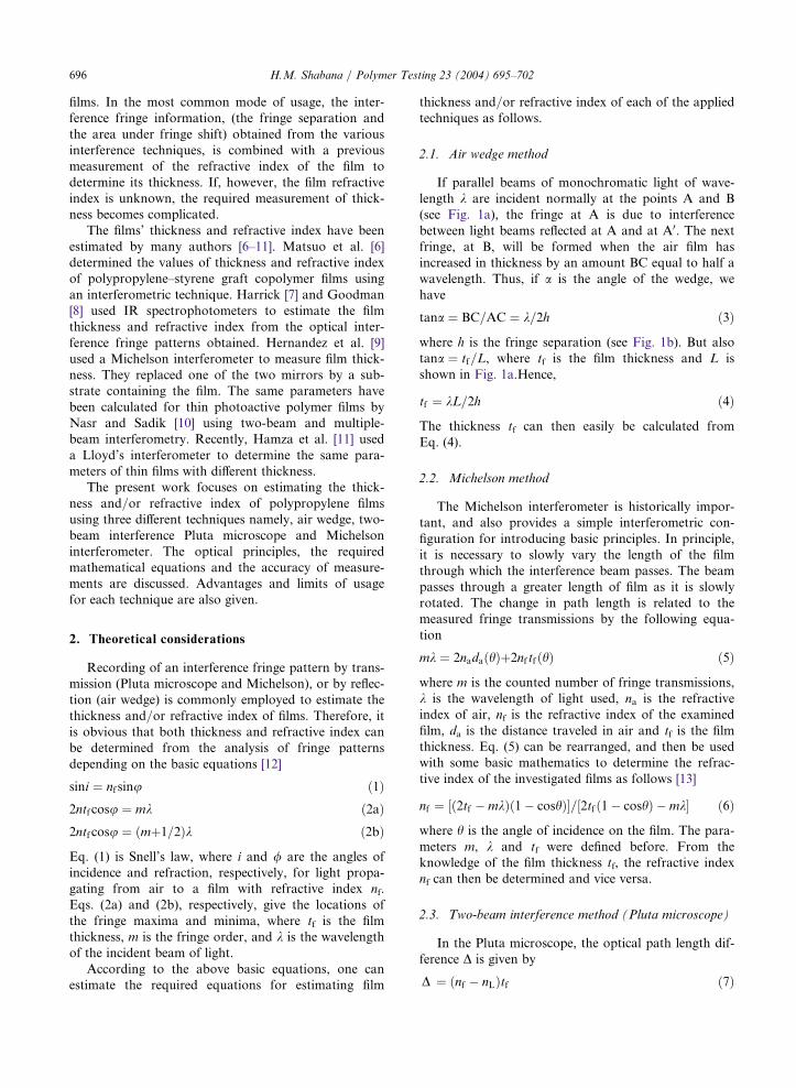
2.1. Air wedge method
If parallel beams of monochromatic light of wave-length k are incident normally at the points A and B(see Fig. 1a), the fringe at A is due to interferencebetween light beams reflected at A and at A0. The nextfringe, at B, will be formed when the air film hasincreased in thickness by an amount BC equal to half awavelength. Thus, if a is the angle of the wedge, wehave
tana ¼ BC=AC ¼ k=2h ð3Þ
where h is the fringe separation (see Fig. 1b). But alsotana ¼ tf=L, where tf is the film thickness and L isshown in Fig. 1a.Hence,
tf ¼ kL=2h ð4Þ
The thickness tf can then easily be calculated fromEq. (4).
2.2. Michelson method
The Michelson interferometer is historically impor-tant, and also provides a simple interferometric con-figuration for introducing basic principles. In principle,it is necessary to slowly vary the length of the filmthrough which the interference beam passes. The beampasses through a greater length of film as it is slowlyrotated. The change in path length is related to themeasured fringe transmissions by the following equa-tion
mk ¼ 2nadaðhÞþ2nf tfðhÞ ð5Þ
where m is the counted number of fringe transmissions,k is the wavelength of light used, na is the refractiveindex of air, nf is the refractive index of the examinedfilm, da is the distance traveled in air and tf is the filmthickness. Eq. (5) can be rearranged, and then be usedwith some basic mathematics to determine the refrac-tive index of the investigated films as follows [13]
nf ¼ ð2tf �mkÞð1� coshÞ½ = 2tfð1� coshÞ �mk½ ð6Þ
where h is the angle of incidence on the film. The para-meters m, k and tf were defined before. From theknowledge of the film thickness tf, the refractive indexnf can then be determined and vice versa.
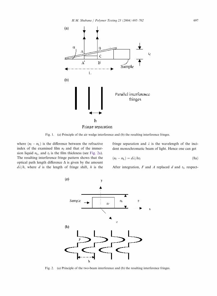
2.3. Two-beam interference method (Pluta microscope)
In the Pluta microscope, the optical path length dif-ference D is given by
D ¼ nf � nLð Þtf ð7Þ
H.M. Shabana / Polymer Testing 23 (2004) 695–702 697
where ðnf � nLÞ is the difference between the refractiveindex of the examined film nf and that of the immer-
sion liquid nL, and tf is the film thickness (see Fig. 2a).
The resulting interference fringe pattern shows that the
optical path length difference D is given by the amountdk=h, where d is the length of fringe shift, h is the
fringe separation and k is the wavelength of the inci-dent monochromatic beam of light. Hence one can get
nf � nLð Þ ¼ dk=htf ð8aÞ
After integration, F and A replaced d and tf, respect-
rinciple of the two-beam interference and (b) the resulting interfe
Fig. 2. (a) P rence fringes.rinciple of the air wedge interference and (b) the resulting interfer
Fig. 1. (a) P ence fringes.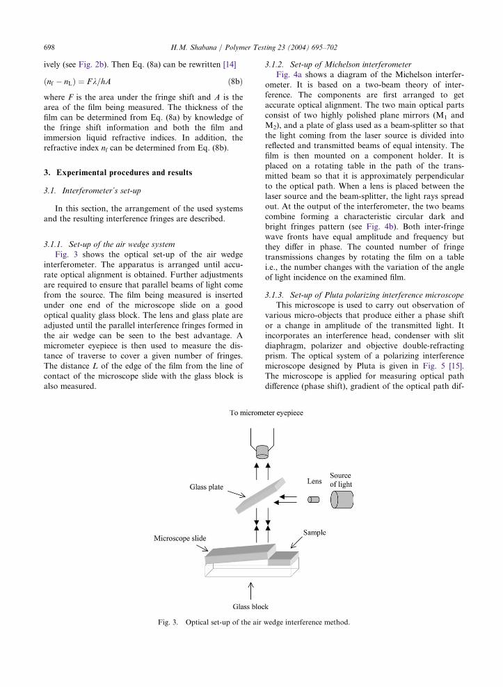
698 H.M. Shabana / Polymer Testing 23 (2004) 695–702
ively (see Fig. 2b). Then Eq. (8a) can be rewritten [14]
nf � nLð Þ ¼ Fk=hA ð8bÞ
where F is the area under the fringe shift and A is thearea of the film being measured. The thickness of thefilm can be determined from Eq. (8a) by knowledge ofthe fringe shift information and both the film andimmersion liquid refractive indices. In addition, therefractive index nf can be determined from Eq. (8b).
3. Experimental procedures and results
3.1. Interferometer’s set-up
In this section, the arrangement of the used systemsand the resulting interference fringes are described.
3.1.1. Set-up of the air wedge systemFig. 3 shows the optical set-up of the air wedge
interferometer. The apparatus is arranged until accu-rate optical alignment is obtained. Further adjustmentsare required to ensure that parallel beams of light comefrom the source. The film being measured is insertedunder one end of the microscope slide on a goodoptical quality glass block. The lens and glass plate areadjusted until the parallel interference fringes formed inthe air wedge can be seen to the best advantage. Amicrometer eyepiece is then used to measure the dis-tance of traverse to cover a given number of fringes.The distance L of the edge of the film from the line ofcontact of the microscope slide with the glass block isalso measured.
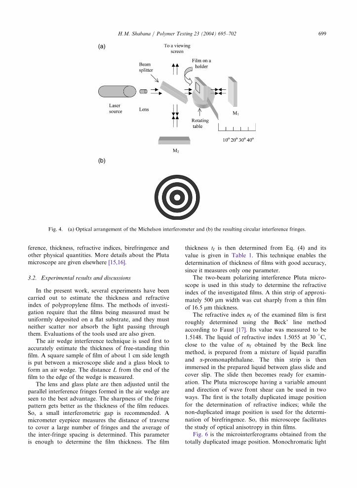
3.1.2. Set-up of Michelson interferometerFig. 4a shows a diagram of the Michelson interfer-
ometer. It is based on a two-beam theory of inter-ference. The components are first arranged to getaccurate optical alignment. The two main optical partsconsist of two highly polished plane mirrors (M1 andM2), and a plate of glass used as a beam-splitter so thatthe light coming from the laser source is divided intoreflected and transmitted beams of equal intensity. Thefilm is then mounted on a component holder. It isplaced on a rotating table in the path of the trans-mitted beam so that it is approximately perpendicularto the optical path. When a lens is placed between thelaser source and the beam-splitter, the light rays spreadout. At the output of the interferometer, the two beamscombine forming a characteristic circular dark andbright fringes pattern (see Fig. 4b). Both inter-fringewave fronts have equal amplitude and frequency butthey differ in phase. The counted number of fringetransmissions changes by rotating the film on a tablei.e., the number changes with the variation of the angleof light incidence on the examined film.
3.1.3. Set-up of Pluta polarizing interference microscopeThis microscope is used to carry out observation of
various micro-objects that produce either a phase shiftor a change in amplitude of the transmitted light. Itincorporates an interference head, condenser with slitdiaphragm, polarizer and objective double-refractingprism. The optical system of a polarizing interferencemicroscope designed by Pluta is given in Fig. 5 [15].The microscope is applied for measuring optical pathdifference (phase shift), gradient of the optical path dif-
Fig. 3. Optical set-up of the air wedge interference method.
H.M. Shabana / Polymer Testing 23 (2004) 695–702 699
ference, thickness, refractive indices, birefringence andother physical quantities. More details about the Plutamicroscope are given elsewhere [15,16].
3.2. Experimental results and discussions
In the present work, several experiments have beencarried out to estimate the thickness and refractiveindex of polypropylene films. The methods of investi-gation require that the films being measured must beuniformly deposited on a flat substrate, and they mustneither scatter nor absorb the light passing throughthem. Evaluations of the tools used are also given.The air wedge interference technique is used first to
accurately estimate the thickness of free-standing thinfilm. A square sample of film of about 1 cm side lengthis put between a microscope slide and a glass block toform an air wedge. The distance L from the end of thefilm to the edge of the wedge is measured.The lens and glass plate are then adjusted until the
parallel interference fringes formed in the air wedge areseen to the best advantage. The sharpness of the fringepattern gets better as the thickness of the film reduces.So, a small interferometric gap is recommended. Amicrometer eyepiece measures the distance of traverseto cover a large number of fringes and the average ofthe inter-fringe spacing is determined. This parameteris enough to determine the film thickness. The film
thickness tf is then determined from Eq. (4) and its
value is given in Table 1. This technique enables the
determination of thickness of films with good accuracy,
since it measures only one parameter.The two-beam polarizing interference Pluta micro-
scope is used in this study to determine the refractive
index of the investigated films. A thin strip of approxi-
mately 500 lm width was cut sharply from a thin filmof 16.5 lm thickness.The refractive index nf of the examined film is first
roughly determined using the Beck’ line method
according to Faust [17]. Its value was measured to be
1.5148. The liquid of refractive index 1.5055 at 30vC,
close to the value of nf obtained by the Beck line
method, is prepared from a mixture of liquid paraffin
and a-promonaphthalane. The thin strip is thenimmersed in the prepared liquid between glass slide and
cover slip. The slide then becomes ready for examin-
ation. The Pluta microscope having a variable amount
and direction of wave front shear can be used in two
ways. The first is the totally duplicated image position
for the determination of refractive indices; while the
non-duplicated image position is used for the determi-
nation of birefringence. So, this microscope facilitates
the study of optical anisotropy in thin films.Fig. 6 is the microinterferograms obtained from the
totally duplicated image position. Monochromatic light
rangement of the Michelson interferometer and (b) the resulting circula
Fig. 4. (a) Optical ar r interference fringes.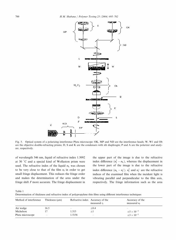
700 H.M. Shabana / Polymer Testing 23 (2004) 695–702
of wavelength 546 nm, liquid of refractive index 1.5092
at 30vC and a special kind of Wollaston prism were
used. The refractive index of the liquid nL was chosen
to be very close to that of the film nf in order to get
small fringe displacement. This reduces the fringe order
and makes the determination of the area under the
fringe shift F more accurate. The fringe displacement in
the upper part of the image is due to the refractive
index difference ðnkf � nLÞ, whereas the displacement inthe lower part of the image is due to the refractive
index difference ðnL � n?f Þ. nkf and n
?f are the refractive
indices of the examined film when the incident light is
vibrating parallel and perpendicular to the film axis,
respectively. The fringe information such as the area
polarizing interference Pluta microscope: OK, MP and ND are the interfer
Fig. 5. Optical system of a ence heads; W, W1 and Obare the objective double-refracting prisms; D, S and K are the condensers with slit diaphragm; P and A are the polarizer and analy-
zer, respectively.
Table 1
Determination of thickness and refractive index of polypropylene thin films using different interference techniques
Method of interference
Thickness (lm) Refractive index Accuracy of themeasured tf
A
m
ccuracy of the
easured nf
Air wedge
16.5 – �0.4 –Michelson
17 1.515 �1 �5 10�3 Pluta microscope – 1.5156 – �3 10�3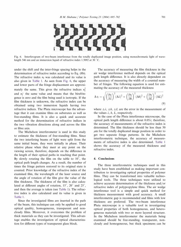
H.M. Shabana / Polymer Testing 23 (2004) 695–702 701
under the shift and the inter-fringe spacing helps in the
determination of refractive index according to Eq. (8b).
The refractive index nf was calculated and its value is
also given in Table 1. As seen from Fig. 6, the upper
and lower parts of the fringe displacement are approxi-
mately the same. This gives the refractive indices nkf
and n?f the same value and means that the birefrin-
gence is zero and the film being used is isotropic. If the
film thickness is unknown, the refractive index can be
obtained using two immersion liquids having two
refractive indices. The Pluta microscope has the advan-
tage that it can examine films on substrates as well as
free-standing films. It is also a quick and accurate
method for the determination of refractive indices in
the two vibration directions along and across the film
or fibre axis.The Michelson interferometer is used in this study
to estimate the thickness of free-standing films. Since
the two interfering beams of light were split from the
same initial beam, they were initially in phase. Their
relative phase when they meet at any point on the
viewing screen, therefore, depends on the difference in
the length of their optical paths in reaching that point.
By slowly rotating the film on the table to 10v, the
optical path length changes. As a result, the number of
times the fringe pattern restored to its original state is
counted. Prior knowledge of the refractive index of the
examined film, the wavelength of the laser source and
the angle of rotation of the film give the value of the
film thickness. The thickness of the film is also calcu-
lated at different angles of rotation, 15v, 20
vand 25
v,
and then the average is taken (see Table 1). The refrac-
tive index is also calculated and its value is given in
Table 1.Since the investigated films are inserted in the path
of the beam, this technique can only be applied to good
optical quality, homogeneous, transparent and non-
cloudy films. Moreover, it overcomes the problem of
thick materials as they can be investigated. This advan-
tage enables the investigation of optical characteriza-
tion for different types of transparent glass block.
The accuracy of measuring the film thickness in theair wedge interference method depends on the opticalpath length difference. It is also directly dependent onthe accuracy of measuring the width of a counted num-ber of fringes. The following equation is used for esti-mating the accuracy of the measured thickness
D tf ¼
ffiffiffiffiffiffiffiffiffiffiffiffiffiffiffiffiffiffiffiffiffiffiffiffiffiffiffiffiffiffiffiffiffiffiffiffiffiffiffiffiffiffiffiffiffiffiffiffiffiffiffiffiffiffiffiffiffiffiffiffiffiffiffiffiffiffiffiffiffiffiffiffiffiffiffiffiffiffiffiffiffiffiffiffiffiffiffiffiffiffiffiffiffi@tf@k
� �2ðDkÞ2 þ @tf
@h
� �2ðDhÞ2 þ @tf
@L
� �2ðDLÞ2
s
ð9Þ
where hk, hh, hL are the error in the measurement ofthe values k, h, L, respectively.In the case of the Pluta interference microscope, the
optical path length difference is about 0.05k; therefore,the accuracy of measurements of the refractive index isdetermined. The film thickness should be less than 50lm for the totally duplicated image position in order toget two separate fringe patterns. In the Michelsoninterferometric technique, the accuracy of measure-ments of refractive index is also determined. Table 1shows the accuracy of the measured thickness andrefractive index.
4. Conclusions
The three interferometric techniques used in thisstudy have been established as making important con-tribution to investigating optical properties of polymerfilms. They can be transformed into valuable techno-logical tools. The three techniques were utilized toachieve accurate determination of the thickness and/orrefractive index of polypropylene films. The air wedgeinterference tool is a simple and quick method forthickness measurement with good accuracy. A smallinterferometric gap is recommended and films with lowthickness are preferred. The two-beam interferencePluta microscope is a valuable tool in investigatingoptical properties of both homogeneous, and hetero-geneous materials with two or more layered structure.In the Michelson interferometer the materials beingexamined should be free-standing, transparent, non-cloudy and homogeneous, but thick specimens can be
m interference from the totally duplicated image position, usinv
Fig. 6. Interferogram of two-bea g monochromatic light of wave-
length 546 nm and an immersion liquid of refractive index 1.5092 at 30 C.
702 H.M. Shabana / Polymer Testing 23 (2004) 695–702
evaluated by this technique. The accuracy, limitationsand advantages of the interferometric techniques usedin this work should be taken into consideration wheninvestigating the optical properties of different types ofmaterial.
Acknowledgements
The author would like to express his appreciation toProf. A.A. Hamza for his support and useful discus-sions. Sincere thanks also to Prof. I.M. Fouda for hisuseful discussions.
References
[1] N. Barakat, A.A. Hamza, Interferometry of Fibrous
Materials, Hilger Bristol, 1990.
[2] I.M. Fouda, H.M. Shabana, J. Phys. Condens. Matter 11
(1999) 3371.
[3] I.M. Fouda, H.M. Shabana, J Appl. Polym. Sci. 82
(2001) 2387.
[4] M. Pluta, Optica Applicata 16 (1986) 301.
[5] M. Pluta, Optica Applicata 17 (1987) 47.
[6] H. Matsuo, K. Hno, M. Kondo, J. Appl. Polym. Sci. 7
(1963) 1833.
[7] N.J. Harrick, Appl. Optics 10 (1971) 2344.
[8] A.M. Goodman, Appl. Optics 17 (1978) 2779.
[9] M. Hernandez, A. Juarez, R. Hernandez, Superficies
Vacio 9 (1999) 283.
[10] A.M. Nasr, A.M. Sadik, J. Opt. A Pure Appl. Opt. 3
(2001) 200.
[11] A.A. Hamza, M.A. Mabrouk, W.A. Ramadan, A.M.
Emara, Opt. Comm. 225 (2003) 341.
[12] F.A. Jenkins, H.E. White, Fundamentals of Optics,
McGraw-Hill, New York, 1950.
[13] Instruction Manual and Experimental Guide for the
Pasco Scientific Model OS-9255 thru 9528, USA, 1990.
[14] A.A. Hamza, J. Microsc. 142 (1986) 35.
[15] M. Pluta, Optica Acta 18 (1971) 661.
[16] M. Pluta, J. Microsc. 96 (1972) 309.
[17] R.C. Faust, Proc. Phys. Soc. B 68 (1955) 1081.