details make the difference - indian cables & electricals - authorized cable...
TRANSCRIPT

XLPE INSULATED HEAVY DUTY CABLES650/1100V.
Detai ls make the Difference
IS 7098 (Part I)
9001:2008
14001:2004
OHSAS18001:2007
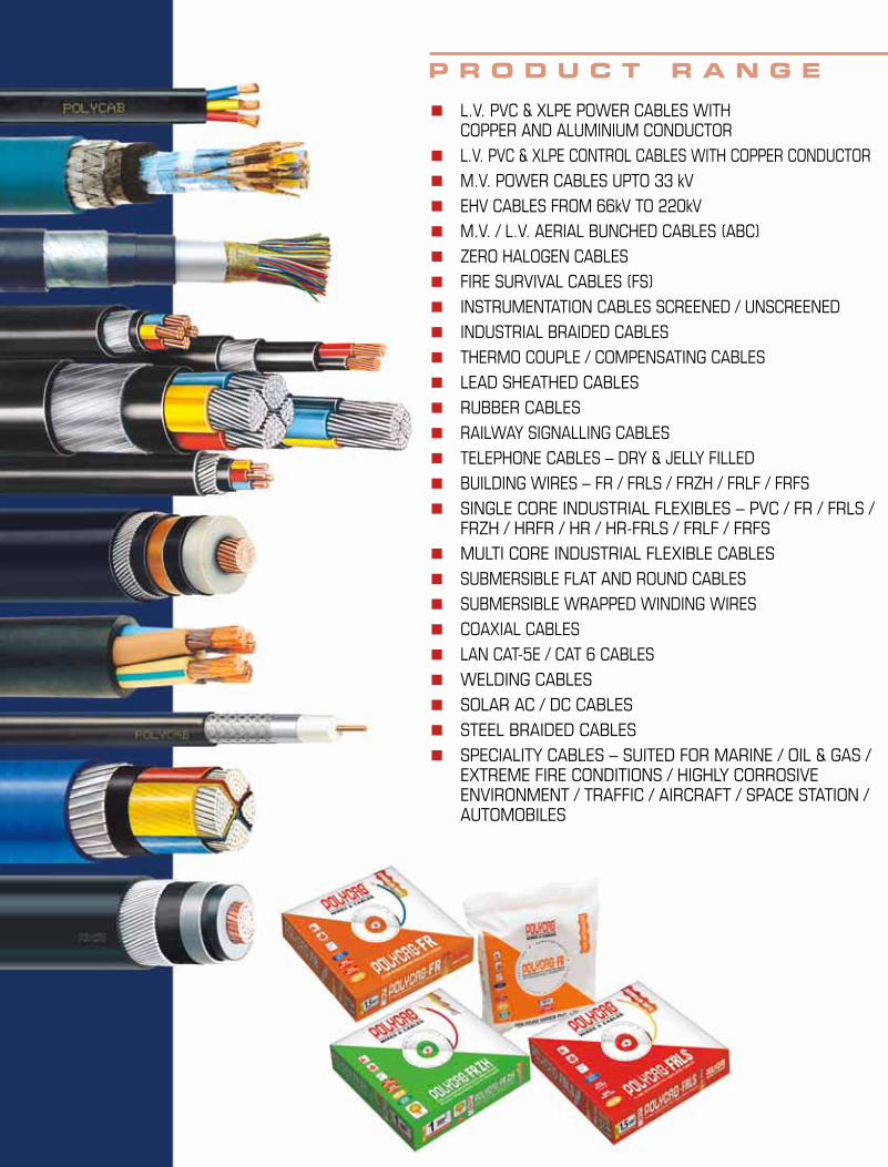
■ L.V. PVC & XLPE POWER CABLES WITH COPPER AND ALUMINIUM CONDUCTOR
■ L.V. PVC & XLPE CONTROL CABLES WITH COPPER CONDUCTOR ■ M.V. POWER CABLES UPTO 33 kV■ EHV CABLES FROM 66kV TO 220kV■ M.V. / L.V. AERIAL BUNCHED CABLES (ABC)■ zERO HALOgEN CABLES■ FIRE SURVIVAL CABLES (FS) ■ INSTRUMENTATION CABLES SCREENED / UNSCREENED■ INDUSTRIAL BRAIDED CABLES■ THERMO COUPLE / COMPENSATINg CABLES ■ LEAD SHEATHED CABLES■ RUBBER CABLES■ RAILWAY SIgNALLINg CABLES■ TELEPHONE CABLES – DRY & JELLY FILLED■ BUILDINg WIRES – FR / FRLS / FRzH / FRLF / FRFS■ SINgLE CORE INDUSTRIAL FLEXIBLES – PVC / FR / FRLS /
FRzH / HRFR / HR / HR-FRLS / FRLF / FRFS■ MULTI CORE INDUSTRIAL FLEXIBLE CABLES■ SUBMERSIBLE FLAT AND ROUND CABLES■ SUBMERSIBLE WRAPPED WINDINg WIRES■ COAXIAL CABLES■ LAN CAT-5E / CAT 6 CABLES■ WELDINg CABLES■ SOLAR AC / DC CABLES■ STEEL BRAIDED CABLES■ SPECIALITY CABLES – SUITED FOR MARINE / OIL & gAS /
EXTREME FIRE CONDITIONS / HIgHLY CORROSIVE ENVIRONMENT / TRAFFIC / AIRCRAFT / SPACE STATION / AUTOMOBILES
P r o d u c t r a n g e
Details make the difference 2
Introduction 3
Advantages of Polycab XLPE Cables & Selection 4
Comparative Current Rating and Short Circuit Rating for XLPE Cable Vis-à-Vis PVC Cables
5
Technical Data 6-7
Tables 8-19
Rating Factors 20-22
Handling 23-24
C o n t e n t s
1
2
Details make the difference
THE COMPANYPOLYCAB, an ISO 9001:2008, ISO 14001:2004, OHSAS 18001:2007 company is the largest Wire & Cable manufacturer in India with a proven track record of over three decades. The fastest growing company in the Indian Cable Industry with consistent growth. Polycab group has crossed Rs. 3600 crore turnover in the year 2010-11 and is set to achieve Rs. 4000 crore turnover in the year 2011–12.
From a modest beginning with Wires and Cables, over three decades ago Polycab set up State of Art manufacturing facilities at Daman in 1996.The last 3 decades have seen the core business develop along different product lines: - Low Voltage Cables, Medium Voltage Cables, Extra High Voltage Cables, Fire Survival & Fire Resistant Cables, Telecommunication Cables, Control & Instrumentation Cables and Aerial Bunched Cables. In the manufacture of cables, a competitive edge lies not so much in product innovation as in providing consistent quality, guaranteeing reliability and ready availability. Polycab’s Daman factory was created to address these key market determinants. The manufacturing set up is sourced out from the world renowned Machinery and Technology suppliers with constant upgradation and expansions.
CUSTOMER SATISFACTIONIn an ongoing process to improve Customer Satisfaction Polycab offers a variety of services:• Commerciallycompetitiveprices.• Reliable&consistentquality.
• Reliable&justintimedelivery.• Product development for a changing
market.• Atargetedstockingpolicy.• Technical Support for Applications/Projects
CUSTOMER FOCUSED POLYCAB derives its strength from its
customers. The growth of the latter is a prerequisite to the growth of the company and hence customers’ satisfaction is its prime objective. Over the years sincereservice and dedication to its Customers has earned the Company distinguished Customers which includes demanding leaders in Sectors like Utilities, Power Generation, Transmission & Distribution, Petroleum & Oil Refineries, Oem’s, EPC contractors, Steel & Metal, Cement, Chemical, Atomic Energy, Nuclear Power, Consultants & Specifiers etc.
POLYCAB has highly experienced, qualified and dedicated professionals with strong adherence to the quality management system. Polycab has offices all over the country and also has a wide network of authorized distributors and dealers to cater to all the customer segments in India and abroad.
POLYCAB has earned the trust and reputation in India and abroad by winning the customers’ confidence. Several thousands kilometers of LT XLPE Cables in the voltage range of 1.1KV have been manufactured and are in operation in India and abroad.
Polycab LT XLPE Cables are preferred choice in Power Plants, Distribution Systems, Heavy Industries, Various Utilities, The TitansofIndianIndustry&Consultants/Specifiers.
DETAILS MAKE THE DIFFERENCE More than 3 decades of experience have enabled POLYCAB to develop a specific know how for each individual productline. Attention to details allows the company to apply optimum technical solutions and material selections to each and every differentprojectorapplication.
Other available Catalogues:Flexible Cables LT PVC Power & Control Cables.HT Cables upto 45KVEHV Cables upto 132KvFire Survival Cables.
Polycab Wires Pvt. Ltd. takes every precaution to ensure the information given in this publication is correct. E & O.E. all information is subject to change without notice.
3
The XLPE insulated heavy duty cables were introduced worldwide in mid sixties. These cables have overcome the limitations of PVC Insulated Cables such as thermal degradation, poor moisture resistant and thermoplastic in nature.
The advantages of XLPE Insulated cables in comparison to PVC insulated cables are as under:
A. Technical Advantages :
1. Higher current rating, higher Short Circuit Rating Approx 1.2 times that of PVC.
2. Thermosetting in nature.
3. Higher insulation resistance – 1000 times more than PVC cables.
4. Higher resistance to moisture.
5. Better Resistance to surge currents.
6. Low Dielectric Losses.
7. Better resistance to chemicals.
8. Longer service life.
9. Comparatively higher cable operation temperature 90°C and short circuit temperature 250°C.
B. Commercial Advantages:
1. Lower laying cost because of comparatively smaller diameter of cable and lighter weight*.
2. Lower installation charges as the diameter of cable is comparatively lesser with smaller bending radius, requiring less space requirement for laying of cables.
3. **One size lower cable can be used as compared to PVC insulated cable.
* Density of XLPE is lower than PVC
**For longer cable length voltage drop shall be considered
XLPE Cables
“BASEC CERTIFICATION OF OUR BUSINESS DEMONSTRATES OUR COMMITMENT TO NOT ONLY THE QUALITY OF OUR PRODUCTS, BUT ALSO THE LEVEL OF OUR COMMITMENT FOR CONTINUOUS IMPROVEMENT”
Polycab Cable of 33KV E 3 x 400 Sq.mm have been successfully type tested at KEMA - Netherland (an internationally acclaimed Testing Laboratory).
4
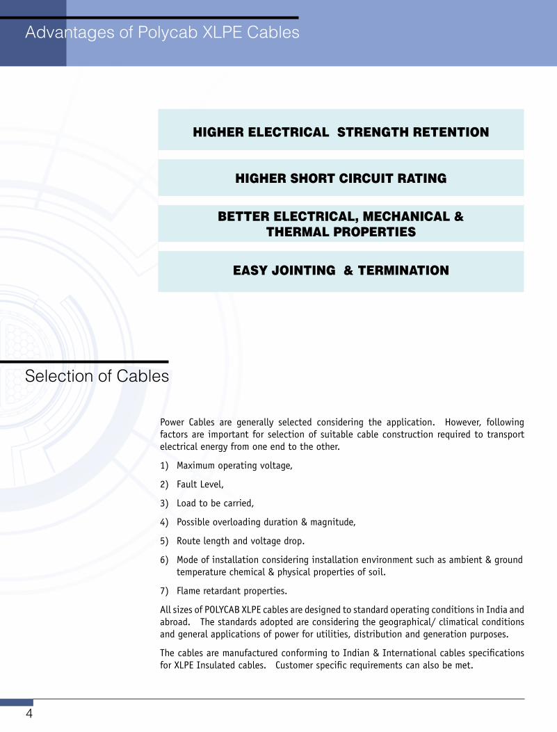
HigHer electricAl StrengtH retentiOn
HigHer SHOrt circuit rAting
Better electricAl, MecHAnicAl & tHerMAl PrOPertieS
eASy JOinting & terMinAtiOn
Advantages of Polycab XLPE Cables
Selection of Cables
Power Cables are generally selected considering the application. However, following factors are important for selection of suitable cable construction required to transport electrical energy from one end to the other.
1) Maximum operating voltage,
2) Fault Level,
3) Load to be carried,
4) Possible overloading duration & magnitude,
5) Route length and voltage drop.
6) Mode of installation considering installation environment such as ambient & ground temperature chemical & physical properties of soil.
7) Flame retardant properties.
All sizes of POLYCAB XLPE cables are designed to standard operating conditions in India and abroad.Thestandardsadoptedareconsideringthegeographical/climaticalconditionsand general applications of power for utilities, distribution and generation purposes.
The cables are manufactured conforming to Indian & International cables specifications for XLPE Insulated cables. Customer specific requirements can also be met.
5
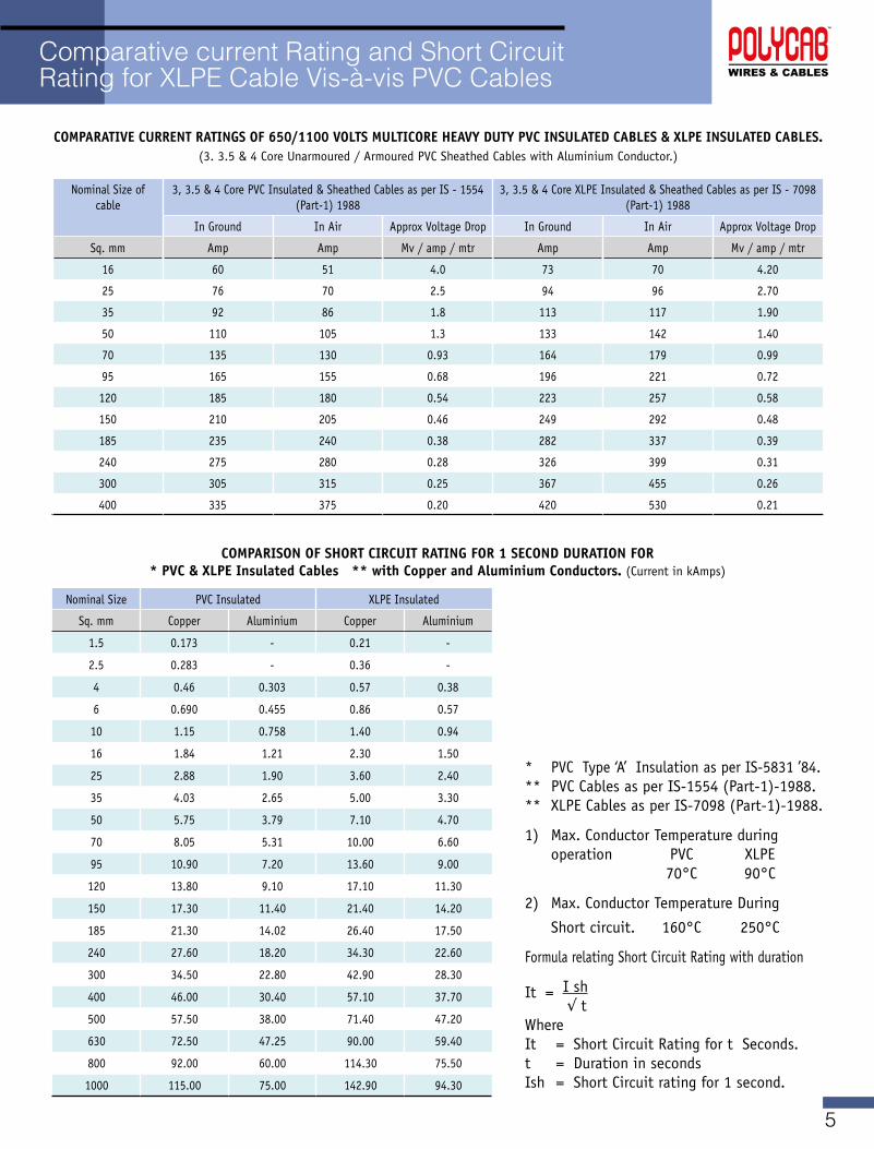
Comparative current Rating and Short Circuit Rating for XLPE Cable Vis-à-vis PVC Cables
COMPARATIvE CURRENT RATINgS OF 650/1100 vOLTS MULTICORE HEAvY DUTY PvC INSULATED CABLES & XLPE INSULATED CABLES.(3.3.5&4CoreUnarmoured/ArmouredPVCSheathedCableswithAluminiumConductor.)
Nominal Size of cable
3, 3.5 & 4 Core PVC Insulated & Sheathed Cables as per IS - 1554 (Part-1) 1988
3, 3.5 & 4 Core XLPE Insulated & Sheathed Cables as per IS - 7098 (Part-1) 1988
In Ground In Air Approx Voltage Drop In Ground In Air Approx Voltage Drop
Sq. mm Amp Amp Mv/amp/mtr Amp Amp Mv/amp/mtr
16 60 51 4.0 73 70 4.20
25 76 70 2.5 94 96 2.70
35 92 86 1.8 113 117 1.90
50 110 105 1.3 133 142 1.40
70 135 130 0.93 164 179 0.99
95 165 155 0.68 196 221 0.72
120 185 180 0.54 223 257 0.58
150 210 205 0.46 249 292 0.48
185 235 240 0.38 282 337 0.39
240 275 280 0.28 326 399 0.31
300 305 315 0.25 367 455 0.26
400 335 375 0.20 420 530 0.21
COMPARISON OF SHORT CIRCUIT RATINg FOR 1 SECOND DURATION FOR * PvC & XLPE Insulated Cables ** with Copper and Aluminium Conductors. (Current in kAmps)
Nominal Size PVC Insulated XLPE Insulated
Sq. mm Copper Aluminium Copper Aluminium
1.5 0.173 - 0.21 -
2.5 0.283 - 0.36 -
4 0.46 0.303 0.57 0.38
6 0.690 0.455 0.86 0.57
10 1.15 0.758 1.40 0.94
16 1.84 1.21 2.30 1.50
25 2.88 1.90 3.60 2.40
35 4.03 2.65 5.00 3.30
50 5.75 3.79 7.10 4.70
70 8.05 5.31 10.00 6.60
95 10.90 7.20 13.60 9.00
120 13.80 9.10 17.10 11.30
150 17.30 11.40 21.40 14.20
185 21.30 14.02 26.40 17.50
240 27.60 18.20 34.30 22.60
300 34.50 22.80 42.90 28.30
400 46.00 30.40 57.10 37.70
500 57.50 38.00 71.40 47.20
630 72.50 47.25 90.00 59.40
800 92.00 60.00 114.30 75.50
1000 115.00 75.00 142.90 94.30
* PVC Type ‘A’ Insulation as per IS-5831 ’84. ** PVC Cables as per IS-1554 (Part-1)-1988. ** XLPE Cables as per IS-7098 (Part-1)-1988.
1) Max. Conductor Temperature during operation PVC XLPE 70°C 90°C
2) Max. Conductor Temperature During
Short circuit. 160°C 250°C
Formula relating Short Circuit Rating with duration
It = I sh √ tWhere It = Short Circuit Rating for t Seconds. t = Duration in seconds Ish = Short Circuit rating for 1 second.
6
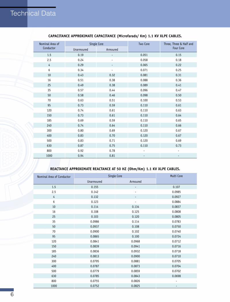
Nominal Area of Conductor
Single Core Two Core Three, Three & Half and Four CoreUnarmoured Armoured
1.5 0.19 - 0.051 0.152.5 0.24 - 0.058 0.18
4 0.29 - 0.065 0.22
6 0.34 - 0.071 0.25
10 0.43 0.32 0.081 0.31
16 0.51 0.38 0.088 0.36
25 0.49 0.38 0.089 0.41
35 0.57 0.44 0.096 0.47
50 0.58 0.46 0.098 0.50
70 0.63 0.51 0.100 0.53
95 0.73 0.59 0.110 0.61
120 0.74 0.61 0.110 0.63
150 0.73 0.61 0.110 0.64
185 0.69 0.59 0.110 0.65
240 0.74 0.64 0.110 0.66
300 0.80 0.69 0.120 0.67
400 0.83 0.70 0.120 0.67
500 0.83 0.71 0.120 0.69
630 0.87 0.75 0.110 0.73
800 0.92 0.78 - -1000 0.94 0.81 - -
CAPACITANCE APPROXIMATE CAPACITANCE (Microfarads/ Km) 1.1 Kv XLPE CABLES.
Nominal Area of Conductor
Single Core Multi Core
Unarmoured Armoured
1.5 0.155 - 0.1072.5 0.142 - 0.09854 0.132 - 0.09276 0.123 - 0.088410 0.114 0.134 0.083716 0.108 0.125 0.080825 0.103 0.120 0.080535 0.0986 0.114 0.078350 0.0937 0.108 0.075070 0.0900 0.102 0.074095 0.0865 0.100 0.0724120 0.0841 0.0968 0.0712150 0.0839 0.0941 0.0716185 0.0836 0.0932 0.0718240 0.0813 0.0900 0.0710300 0.0795 0.0881 0.0705400 0.0787 0.0873 0.0704500 0.0779 0.0859 0.0702630 0.0785 0.0843 0.0698800 0.0755 0.0826 -1000 0.0752 0.0825 -
REACTANCE APPROXIMATE REACTANCE AT 50 HZ (Ohm/Km) 1.1 Kv XLPE CABLES.
Technical Data
7
* These sizes can be manufactured with solid conductor having single strand
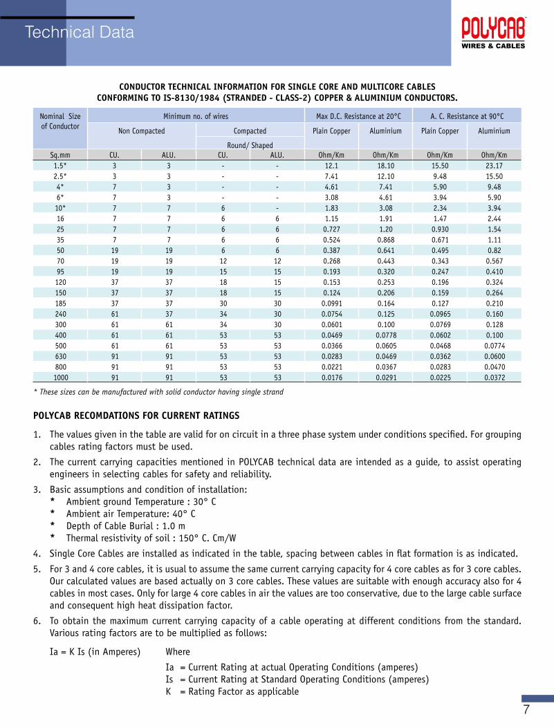
POLYCAB RECOMDATIONS FOR CURRENT RATINgS
1. The values given in the table are valid for on circuit in a three phase system under conditions specified. For grouping cables rating factors must be used.
2. The current carrying capacities mentioned in POLYCAB technical data are intended as a guide, to assist operating engineers in selecting cables for safety and reliability.
3. Basic assumptions and condition of installation: * Ambient ground Temperature : 30° C * Ambient air Temperature: 40° C * Depth of Cable Burial : 1.0 m * Thermal resistivity of soil : 150°C.Cm/W
4. Single Core Cables are installed as indicated in the table, spacing between cables in flat formation is as indicated.
5. For 3 and 4 core cables, it is usual to assume the same current carrying capacity for 4 core cables as for 3 core cables. Our calculated values are based actually on 3 core cables. These values are suitable with enough accuracy also for 4 cables in most cases. Only for large 4 core cables in air the values are too conservative, due to the large cable surface and consequent high heat dissipation factor.
6. To obtain the maximum current carrying capacity of a cable operating at different conditions from the standard. Various rating factors are to be multiplied as follows:
Ia = K Is (in Amperes) Where
Ia = Current Rating at actual Operating Conditions (amperes) Is = Current Rating at Standard Operating Conditions (amperes) K = Rating Factor as applicable
CONDUCTOR TECHNICAL INFORMATION FOR SINgLE CORE AND MULTICORE CABLES CONFORMINg TO IS-8130/1984 (STRANDED - CLASS-2) COPPER & ALUMINIUM CONDUCTORS.
Nominal Size of Conductor
Minimum no. of wires Max D.C. Resistance at 20°C A. C. Resistance at 90°C
Non Compacted Compacted Plain Copper Aluminium Plain Copper Aluminium
Round/ShapedSq.mm CU. ALU. CU. ALU. Ohm/Km Ohm/Km Ohm/Km Ohm/Km1.5* 3 3 - - 12.1 18.10 15.50 23.172.5* 3 3 - - 7.41 12.10 9.48 15.504* 7 3 - - 4.61 7.41 5.90 9.486* 7 3 - - 3.08 4.61 3.94 5.9010* 7 7 6 - 1.83 3.08 2.34 3.9416 7 7 6 6 1.15 1.91 1.47 2.4425 7 7 6 6 0.727 1.20 0.930 1.5435 7 7 6 6 0.524 0.868 0.671 1.1150 19 19 6 6 0.387 0.641 0.495 0.8270 19 19 12 12 0.268 0.443 0.343 0.56795 19 19 15 15 0.193 0.320 0.247 0.410120 37 37 18 15 0.153 0.253 0.196 0.324150 37 37 18 15 0.124 0.206 0.159 0.264185 37 37 30 30 0.0991 0.164 0.127 0.210240 61 37 34 30 0.0754 0.125 0.0965 0.160300 61 61 34 30 0.0601 0.100 0.0769 0.128400 61 61 53 53 0.0469 0.0778 0.0602 0.100500 61 61 53 53 0.0366 0.0605 0.0468 0.0774630 91 91 53 53 0.0283 0.0469 0.0362 0.0600800 91 91 53 53 0.0221 0.0367 0.0283 0.04701000 91 91 53 53 0.0176 0.0291 0.0225 0.0372
Technical Data
8
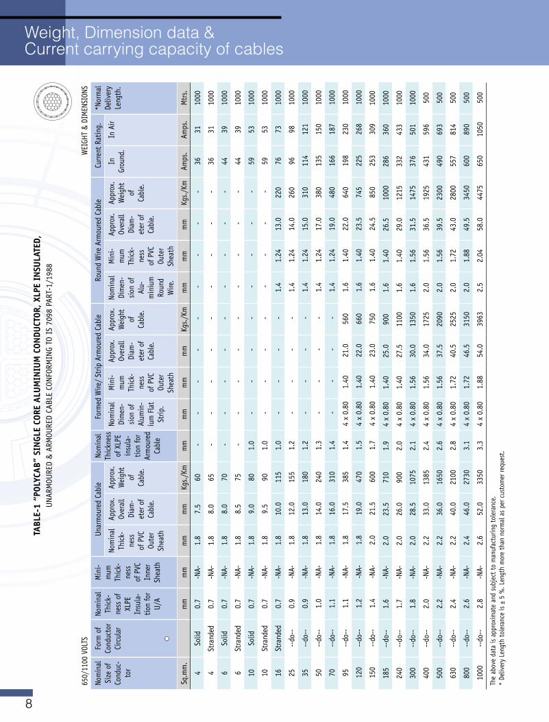
Weight, Dimension data & Current carrying capacity of cables
TABL
E-1
“POL
YCAB
” SI
NgL
E CO
RE A
LUM
INIU
M C
ONDU
CTOR
, XLP
E IN
SULA
TED,
UNARMOURED&ARMOUREDCABLECONFORMINGTOIS7098PART-1/1988
650/1100VOLTS
WEIGHT&DIMENSIONS
Nom
inal
Si
ze o
f Co
nduc
-to
r
Form
of
Cond
ucto
r Ci
rcul
ar
Nom
inal
Th
ick-
ness
of
XLPE
In
sula
-tio
n fo
r U/A
Min
i-m
um
Thic
k-ne
ss
of P
VC
Inne
r Sh
eath
Unar
mou
red
Cabl
eNo
min
al
Thic
knes
s of
XLP
E in
sula
-tio
n fo
r Ar
mou
red
Cabl
e
FormedWire/StripArmouredCable
Roun
d W
ire A
rmou
red
Cabl
eCu
rrent
Rat
ing.
*Nor
mal
De
liver
y Le
ngth
. No
min
al
Thic
k-ne
ss
of P
VC
Oute
r Sh
eath
Appr
ox.
Over
all
Diam
-et
er o
f Ca
ble.
Appr
ox.
Wei
ght
of
Cabl
e.
Nom
inal
Di
men
-sio
n of
Al
umin
-iu
m F
lat
Strip
.
Min
i-m
um
Thic
k-ne
ss
of P
VC
Oute
r Sh
eath
Appr
ox.
Over
all
Diam
-et
er o
f Ca
ble.
Appr
ox.
Wei
ght
of
Cabl
e.
Nom
inal
Di
men
-sio
n of
Al
u-m
iniu
m
Roun
d W
ire.
Min
i-m
um
Thic
k-ne
ss
of P
VC
Oute
r Sh
eath
Appr
ox.
Over
all
Diam
-et
er o
f Ca
ble.
Appr
ox.
Wei
ght
of
Cabl
e.
In
Grou
nd.
In A
ir
Sq.m
m.
mm
mm
mm
mm
Kgs./Km
mm
mm
mm
mm
Kgs./Km
mm
mm
mm
Kgs./Km
Amps
.Am
ps.
Mtr
s.
4So
lid0.
7-N
A-1.
87.
560
- -
- -
- -
- -
-36
3110
00
4St
rand
ed0.
7-N
A-1.
88.
065
- -
- -
- -
- -
-36
3110
00
6So
lid0.
7-N
A-1.
88.
070
- -
- -
- -
- -
-44
3910
00
6St
rand
ed0.
7-N
A-1.
88.
575
- -
- -
- -
- -
-44
3910
00
10So
lid0.
7-N
A-1.
89.
080
1.0
- -
- -
- -
- -
5953
1000
10St
rand
ed0.
7-N
A-1.
89.
590
1.0
- -
- -
- -
- -
5953
1000
16St
rand
ed0.
7-N
A-1.
810
.011
51.
0 -
- -
-1.
41.
2413
.022
076
7310
00
25--
do--
0.9
-NA-
1.8
12.0
155
1.2
- -
- -
1.4
1.24
14.0
260
9698
1000
35--
do--
0.9
-NA-
1.8
13.0
180
1.2
- -
- -
1.4
1.24
15.0
310
114
121
1000
50--
do--
1.0
-NA-
1.8
14.0
240
1.3
- -
- -
1.4
1.24
17.0
380
135
150
1000
70--
do--
1.1
-NA-
1.8
16.0
310
1.4
- -
- -
1.4
1.24
19.0
480
166
187
1000
95--
do--
1.1
-NA-
1.8
17.5
385
1.4
4 x
0.80
1.40
21.0
560
1.6
1.40
22.0
640
198
230
1000
120
--do
--1.
2-N
A-1.
819
.047
01.
54
x 0.
801.
4022
.066
01.
61.
4023
.574
522
526
810
00
150
--do
--1.
4-N
A-2.
021
.560
01.
74
x 0.
801.
4023
.075
01.
61.
4024
.585
025
330
910
00
185
--do
--1.
6-N
A-2.
023
.571
01.
94
x 0.
801.
4025
.090
01.
61.
4026
.510
0028
636
010
00
240
--do
--1.
7-N
A-2.
026
.090
02.
04
x 0.
801.
4027
.511
001.
61.
4029
.012
1533
243
310
00
300
--do
--1.
8-N
A-2.
028
.510
752.
14
x 0.
801.
5630
.013
501.
61.
5631
.514
7537
650
110
00
400
--do
--2.
0-N
A-2.
233
.013
852.
44
x 0.
801.
5634
.017
252.
01.
5636
.519
2543
159
650
0
500
--do
--2.
2-N
A-2.
236
.016
502.
64
x 0.
801.
5637
.520
902.
01.
5639
.523
0049
069
350
0
630
--do
--2.
4-N
A-2.
240
.021
002.
84
x 0.
801.
7240
.525
252.
01.
7243
.028
0055
781
450
0
800
--do
--2.
6-N
A-2.
446
.027
303.
14
x 0.
801.
7246
.531
502.
01.
8849
.534
5060
089
050
0
1000
--do
--2.
8-N
A-2.
652
.033
503.
34
x 0.
801.
8854
.039
632.
52.
0458
.044
7565
010
5050
0
Theabovedataisapproximateandsubjecttomanufacturingtolerance.
* De
liver
y Le
ngth
tole
ranc
e is
± 5
%. L
engt
h m
ore
than
nor
mal
as
per c
usto
mer
requ
est.
9
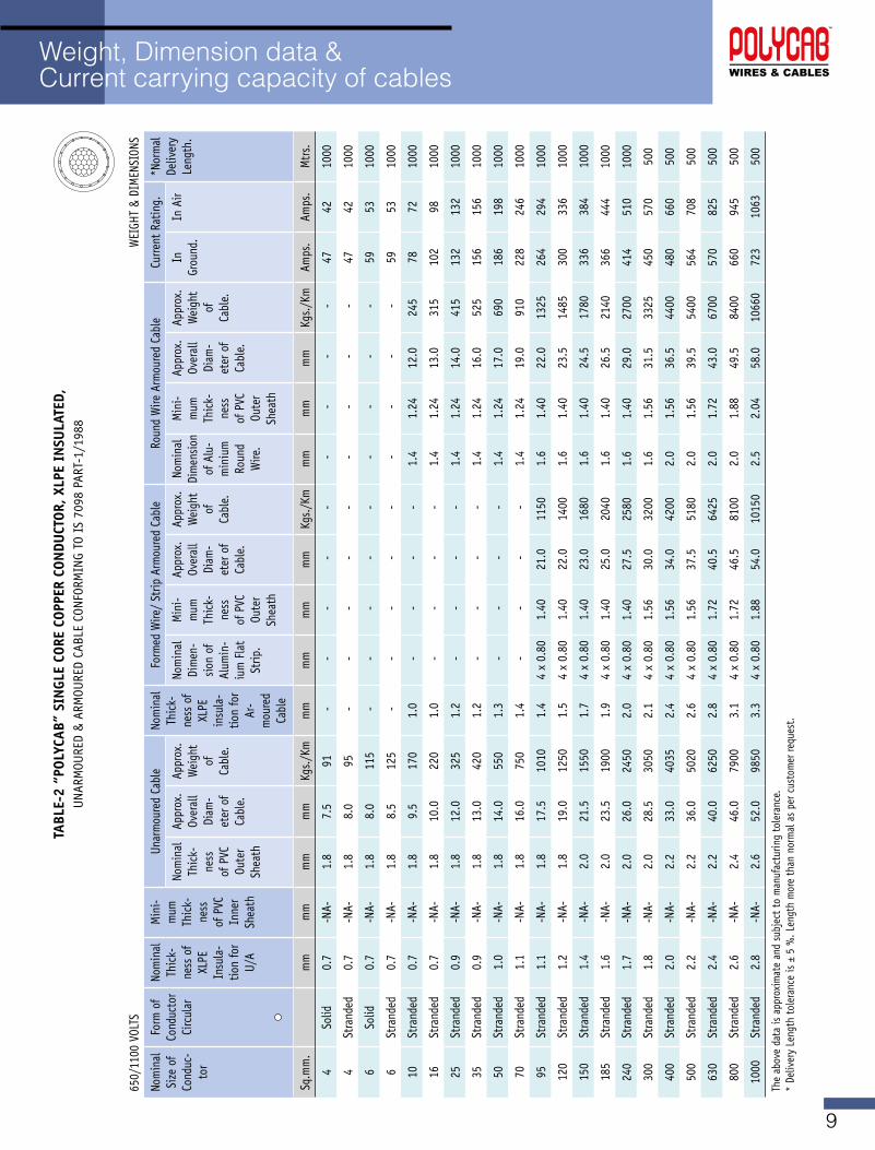
Weight, Dimension data & Current carrying capacity of cables
TABL
E-2
“POL
YCAB
” SI
NgL
E CO
RE C
OPPE
R CO
NDU
CTOR
, XLP
E IN
SULA
TED,
UNARMOURED&ARMOUREDCABLECONFORMINGTOIS7098PART-1/1988
650/1100VOLTS
WEIGHT&DIMENSIONS
Nom
inal
Si
ze o
f Co
nduc
-to
r
Form
of
Cond
ucto
r Ci
rcul
ar
Nom
inal
Th
ick-
ness
of
XLPE
In
sula
-tio
n fo
r U/A
Min
i-m
um
Thic
k-ne
ss
of P
VC
Inne
r Sh
eath
Unar
mou
red
Cabl
eNo
min
al
Thic
k-ne
ss o
f XL
PE
insu
la-
tion
for
Ar-
mou
red
Cabl
e
FormedWire/StripArmouredCable
Roun
d W
ire A
rmou
red
Cabl
eCu
rrent
Rat
ing.
*Nor
mal
De
liver
y Le
ngth
. No
min
al
Thic
k-ne
ss
of P
VC
Oute
r Sh
eath
Appr
ox.
Over
all
Diam
-et
er o
f Ca
ble.
Appr
ox.
Wei
ght
of
Cabl
e.
Nom
inal
Di
men
-sio
n of
Al
umin
-iu
m F
lat
Strip
.
Min
i-m
um
Thic
k-ne
ss
of P
VC
Oute
r Sh
eath
Appr
ox.
Over
all
Diam
-et
er o
f Ca
ble.
Appr
ox.
Wei
ght
of
Cabl
e.
Nom
inal
Di
men
sion
of A
lu-
min
ium
Ro
und
Wire
.
Min
i-m
um
Thic
k-ne
ss
of P
VC
Oute
r Sh
eath
Appr
ox.
Over
all
Diam
-et
er o
f Ca
ble.
Appr
ox.
Wei
ght
of
Cabl
e.
In
Grou
nd.
In A
ir
Sq.m
m.
mm
mm
mm
mm
Kgs./Km
mm
mm
mm
mm
Kgs./Km
mm
mm
mm
Kgs./Km
Amps
.Am
ps.
Mtr
s.
4So
lid0.
7-N
A-1.
87.
591
- -
- -
- -
- -
-47
4210
00
4St
rand
ed0.
7-N
A-1.
88.
095
- -
- -
- -
- -
-47
4210
00
6So
lid0.
7-N
A-1.
88.
011
5 -
- -
- -
- -
- -
5953
1000
6St
rand
ed0.
7-N
A-1.
88.
512
5 -
- -
- -
- -
- -
5953
1000
10St
rand
ed0.
7-N
A-1.
89.
517
01.
0 -
- -
-1.
41.
2412
.024
578
7210
00
16St
rand
ed0.
7-N
A-1.
810
.022
01.
0 -
- -
-1.
41.
2413
.031
510
298
1000
25St
rand
ed0.
9-N
A-1.
812
.032
51.
2 -
- -
-1.
41.
2414
.041
513
213
210
00
35St
rand
ed0.
9-N
A-1.
813
.042
01.
2 -
- -
-1.
41.
2416
.052
515
615
610
00
50St
rand
ed1.
0-N
A-1.
814
.055
01.
3 -
- -
-1.
41.
2417
.069
018
619
810
00
70St
rand
ed1.
1-N
A-1.
816
.075
01.
4 -
- -
-1.
41.
2419
.091
022
824
610
00
95St
rand
ed1.
1-N
A-1.
817
.510
101.
44
x 0.
801.
4021
.011
501.
61.
4022
.013
2526
429
410
00
120
Stra
nded
1.2
-NA-
1.8
19.0
1250
1.5
4 x
0.80
1.40
22.0
1400
1.6
1.40
23.5
1485
300
336
1000
150
Stra
nded
1.4
-NA-
2.0
21.5
1550
1.7
4 x
0.80
1.40
23.0
1680
1.6
1.40
24.5
1780
336
384
1000
185
Stra
nded
1.6
-NA-
2.0
23.5
1900
1.9
4 x
0.80
1.40
25.0
2040
1.6
1.40
26.5
2140
366
444
1000
240
Stra
nded
1.7
-NA-
2.0
26.0
2450
2.0
4 x
0.80
1.40
27.5
2580
1.6
1.40
29.0
2700
414
510
1000
300
Stra
nded
1.8
-NA-
2.0
28.5
3050
2.1
4 x
0.80
1.56
30.0
3200
1.6
1.56
31.5
3325
450
570
500
400
Stra
nded
2.0
-NA-
2.2
33.0
4035
2.4
4 x
0.80
1.56
34.0
4200
2.0
1.56
36.5
4400
480
660
500
500
Stra
nded
2.2
-NA-
2.2
36.0
5020
2.6
4 x
0.80
1.56
37.5
5180
2.0
1.56
39.5
5400
564
708
500
630
Stra
nded
2.4
-NA-
2.2
40.0
6250
2.8
4 x
0.80
1.72
40.5
6425
2.0
1.72
43.0
6700
570
825
500
800
Stra
nded
2.6
-NA-
2.4
46.0
7900
3.1
4 x
0.80
1.72
46.5
8100
2.0
1.88
49.5
8400
660
945
500
1000
Stra
nded
2.8
-NA-
2.6
52.0
9850
3.3
4 x
0.80
1.88
54.0
1015
02.
52.
0458
.010
660
723
1063
500
Theabovedataisapproximateandsubjecttomanufacturingtolerance.
* De
liver
y Le
ngth
tole
ranc
e is
± 5
%. L
engt
h m
ore
than
nor
mal
as
per c
usto
mer
requ
est.
10
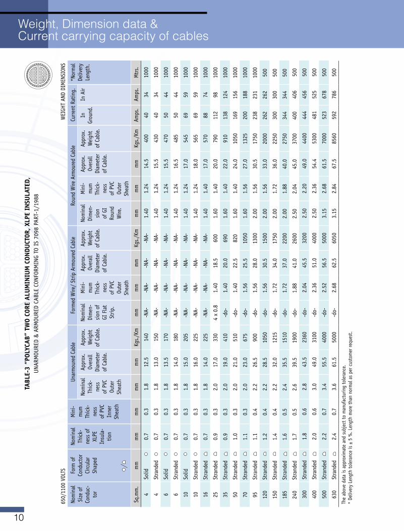
Weight, Dimension data & Current carrying capacity of cables
TABL
E-3
“POL
YCAB
” TW
O CO
RE A
LUM
INIU
M C
ONDU
CTOR
, XLP
E IN
SULA
TED,
UNARMOURED&ARMOUREDCABLECONFORMINGTOIS7098PART-1/1988
650/1100VOLTS
WEIGHTANDDIMENSIONS
Nom
inal
Si
ze o
f Co
nduc
-to
r
Form
of
Cond
ucto
r Ci
rcul
ar
Shap
ed
Nom
inal
Th
ick-
ness
of
XLPE
In
sula
-tio
n
Min
i-m
um
Thic
k-ne
ss
of P
VC
Inne
r Sh
eath
Unar
mou
red
Cabl
eFormedWire/StripArmouredCable
Roun
d W
ire A
rmou
red
Cabl
eCu
rrent
Rat
ing.
*Nor
mal
De
liver
y Le
ngth
. No
min
al
Thic
k-ne
ss
of P
VC
Oute
r Sh
eath
Appr
ox.
Over
all
Diam
eter
of
Cab
le.
Appr
ox.
Wei
ght
of C
able
.
Nom
inal
Di
men
-sio
n of
GI
Fla
t St
rip.
Min
i-m
um
Thic
k-ne
ss
of P
VC
Oute
r Sh
eath
Appr
ox.
Over
all
Diam
eter
of
Cab
le.
Appr
ox.
Wei
ght
of C
able
.
Nom
inal
Di
men
-sio
n of
GI
Roun
d W
ire.
Min
i-m
um
Thic
k-ne
ss
of P
VC
Oute
r Sh
eath
Appr
ox.
Over
all
Diam
eter
of
Cab
le.
Appr
ox.
Wei
ght
of C
able
.
In
Grou
nd.
In A
ir
Sq.m
m.
mm
mm
mm
mm
mm
Kgs./Km
mm
mm
mm
Kgs./Km
mm
mm
mm
Kgs./Km
Amps
.Am
ps.
Mtr
s.
4So
lid0.
70.
31.
812
.514
0-N
A--N
A--N
A--N
A-1.
401.
2414
.540
040
3410
00
4St
rand
ed
0.7
0.3
1.8
13.0
150
-NA-
-NA-
-NA-
-NA-
1.40
1.24
15.5
430
4034
1000
6So
lid0.
70.
31.
813
.517
0-N
A--N
A--N
A--N
A-1.
401.
2415
.547
050
4410
00
6St
rand
ed
0.7
0.3
1.8
14.0
180
-NA-
-NA-
-NA-
-NA-
1.40
1.24
16.5
485
5044
1000
10So
lid0.
70.
31.
815
.020
5-N
A--N
A--N
A--N
A-1.
401.
2417
.054
569
5910
00
10St
rand
ed
0.7
0.3
1.8
16.0
225
-NA-
-NA-
-NA-
-NA-
1.40
1.24
18.0
565
6959
1000
16St
rand
ed
0.7
0.3
1.8
14.0
225
-NA-
-NA-
-NA-
-NA-
1.40
1.40
17.0
570
8874
1000
25St
rand
ed
0.9
0.3
2.0
17.0
330
4 x
0.8
1.40
18.5
600
1.60
1.40
20.0
790
112
9810
00
35St
rand
ed
0.9
0.3
2.0
19.0
410
-do-
1.40
20.0
690
1.60
1.40
22.0
910
138
124
1000
50St
rand
ed
1.0
0.3
2.0
21.0
510
-do-
1.40
22.5
820
1.60
1.40
24.0
1050
169
156
1000
70St
rand
ed
1.1
0.3
2.0
23.0
675
-do-
1.56
25.5
1050
1.60
1.56
27.0
1325
200
188
1000
95St
rand
ed
1.1
0.4
2.2
26.5
900
-do-
1.56
28.0
1300
2.00
1.56
30.5
1750
238
231
1000
120
Stra
nded
1.
20.
42.
228
.510
50-d
o-1.
5630
.515
002.
001.
5633
.020
0026
226
250
0
150
Stra
nded
1.
40.
42.
232
.012
15-d
o-1.
7234
.017
502.
001.
7236
.022
5030
030
050
0
185
Stra
nded
1.
60.
52.
435
.515
10-d
o-1.
7237
.022
002.
001.
8840
.027
5034
434
450
0
240
Stra
nded
1.
70.
52.
639
.519
00-d
o-1.
8841
.026
002.
502.
0445
.037
0040
040
650
0
300
Stra
nded
1.
80.
62.
843
.523
60-d
o-2.
0445
.532
002.
502.
2049
.044
0044
445
650
0
400
Stra
nded
2.
00.
63.
049
.031
00-d
o-2.
3651
.040
002.
502.
3654
.453
0048
152
550
0
500
Stra
nded
2.
20.
73.
455
.540
00-d
o-2.
5256
.550
003.
152.
6861
.570
0052
367
850
0
630
Stra
nded
2.
40.
73.
661
.550
00-d
o-2.
6862
.560
503.
152.
8467
.585
6059
278
650
0
Theabovedataisapproximateandsubjecttomanufacturingtolerance.
* De
liver
y Le
ngth
tole
ranc
e is
± 5
%. L
engt
h m
ore
than
nor
mal
as
per c
usto
mer
requ
est.
11
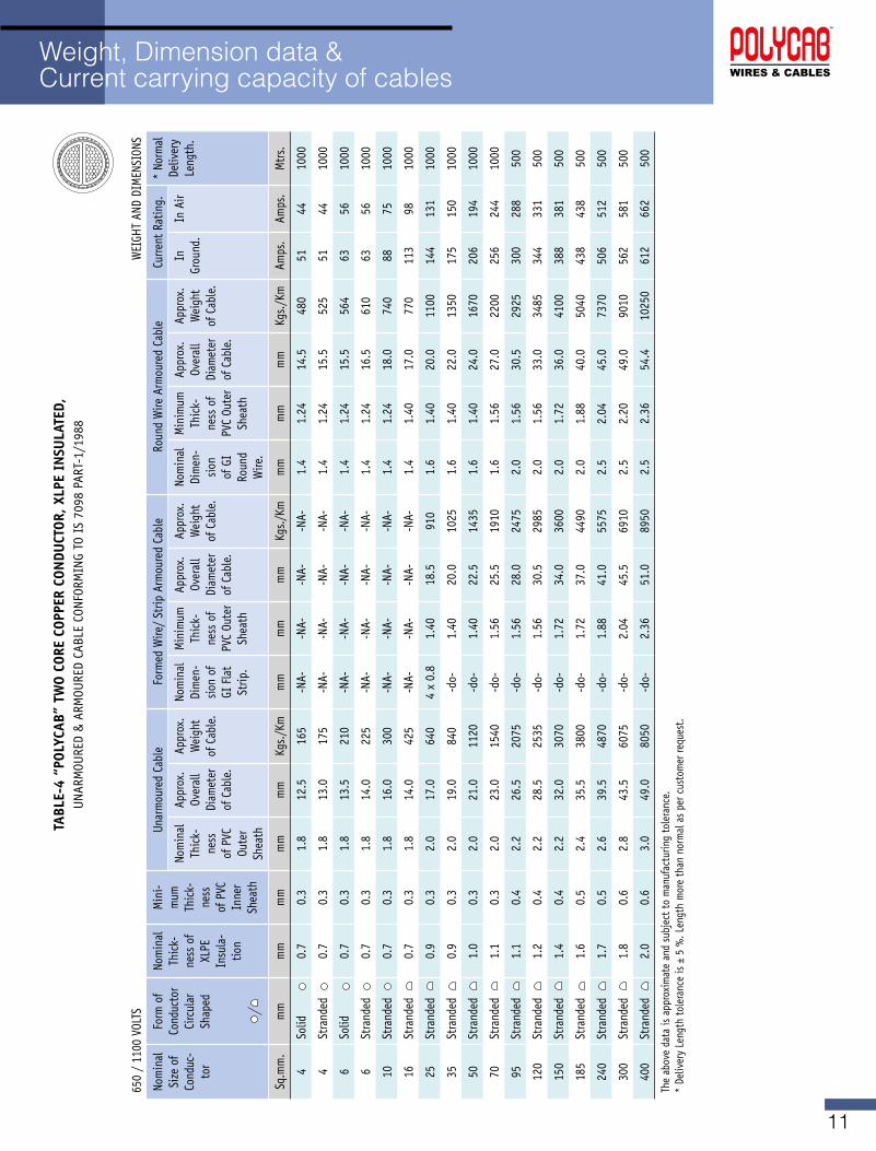
Weight, Dimension data & Current carrying capacity of cables
TABL
E-4
“POL
YCAB
” TW
O CO
RE C
OPPE
R CO
NDU
CTOR
, XLP
E IN
SULA
TED,
UNARMOURED&ARMOUREDCABLECONFORMINGTOIS7098PART-1/1988
650/1100VOLTS
WEIGHTANDDIMENSIONS
Nom
inal
Si
ze o
f Co
nduc
-to
r
Form
of
Cond
ucto
r Ci
rcul
ar
Shap
ed
Nom
inal
Th
ick-
ness
of
XLPE
In
sula
-tio
n
Min
i-m
um
Thic
k-ne
ss
of P
VC
Inne
r Sh
eath
Unar
mou
red
Cabl
eFormedWire/StripArmouredCable
Roun
d W
ire A
rmou
red
Cabl
eCu
rrent
Rat
ing.
* No
rmal
De
liver
y Le
ngth
. No
min
al
Thic
k-ne
ss
of P
VC
Oute
r Sh
eath
Appr
ox.
Over
all
Diam
eter
of
Cab
le.
Appr
ox.
Wei
ght
of C
able
.
Nom
inal
Di
men
-sio
n of
GI
Fla
t St
rip.
Min
imum
Th
ick-
ness
of
PVC
Oute
r Sh
eath
Appr
ox.
Over
all
Diam
eter
of
Cab
le.
Appr
ox.
Wei
ght
of C
able
.
Nom
inal
Di
men
-sio
n of
GI
Roun
d W
ire.
Min
imum
Th
ick-
ness
of
PVC
Oute
r Sh
eath
Appr
ox.
Over
all
Diam
eter
of
Cab
le.
Appr
ox.
Wei
ght
of C
able
.
In
Grou
nd.
In A
ir
Sq.m
m.
mm
mm
mm
mm
mm
Kgs./Km
mm
mm
mm
Kgs./Km
mm
mm
mm
Kgs./Km
Amps
.Am
ps.
Mtr
s.
4So
lid0.
70.
31.
812
.516
5-N
A--N
A--N
A--N
A-1.
41.
2414
.548
051
4410
00
4St
rand
ed
0.7
0.3
1.8
13.0
175
-NA-
-NA-
-NA-
-NA-
1.4
1.24
15.5
525
5144
1000
6So
lid0.
70.
31.
813
.521
0-N
A--N
A--N
A--N
A-1.
41.
2415
.556
463
5610
00
6St
rand
ed
0.7
0.3
1.8
14.0
225
-NA-
-NA-
-NA-
-NA-
1.4
1.24
16.5
610
6356
1000
10St
rand
ed
0.7
0.3
1.8
16.0
300
-NA-
-NA-
-NA-
-NA-
1.4
1.24
18.0
740
8875
1000
16St
rand
ed
0.7
0.3
1.8
14.0
425
-NA-
-NA-
-NA-
-NA-
1.4
1.40
17.0
770
113
9810
00
25St
rand
ed
0.9
0.3
2.0
17.0
640
4 x
0.8
1.40
18.5
910
1.6
1.40
20.0
1100
144
131
1000
35St
rand
ed
0.9
0.3
2.0
19.0
840
-do-
1.40
20.0
1025
1.6
1.40
22.0
1350
175
150
1000
50St
rand
ed
1.0
0.3
2.0
21.0
1120
-do-
1.40
22.5
1435
1.6
1.40
24.0
1670
206
194
1000
70St
rand
ed
1.1
0.3
2.0
23.0
1540
-do-
1.56
25.5
1910
1.6
1.56
27.0
2200
256
244
1000
95St
rand
ed
1.1
0.4
2.2
26.5
2075
-do-
1.56
28.0
2475
2.0
1.56
30.5
2925
300
288
500
120
Stra
nded
1.
20.
42.
228
.525
35-d
o-1.
5630
.529
852.
01.
5633
.034
8534
433
150
0
150
Stra
nded
1.
40.
42.
232
.030
70-d
o-1.
7234
.036
002.
01.
7236
.041
0038
838
150
0
185
Stra
nded
1.
60.
52.
435
.538
00-d
o-1.
7237
.044
902.
01.
8840
.050
4043
843
850
0
240
Stra
nded
1.
70.
52.
639
.548
70-d
o-1.
8841
.055
752.
52.
0445
.073
7050
651
250
0
300
Stra
nded
1.
80.
62.
843
.560
75-d
o-2.
0445
.569
102.
52.
2049
.090
1056
258
150
0
400
Stra
nded
2.
00.
63.
049
.080
50-d
o-2.
3651
.089
502.
52.
3654
.410
250
612
662
500
Theabovedataisapproximateandsubjecttomanufacturingtolerance.
* De
liver
y Le
ngth
tole
ranc
e is
± 5
%. L
engt
h m
ore
than
nor
mal
as
per c
usto
mer
requ
est.
12
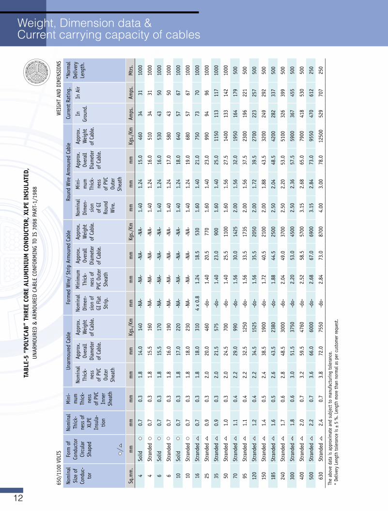
Weight, Dimension data & Current carrying capacity of cables
TABL
E-5
“POL
YCAB
” TH
REE
CORE
ALU
MIN
IUM
CON
DUCT
OR, X
LPE
INSU
LATE
D,UNARMOURED&ARMOUREDCABLECONFORMINGTOIS7098PART-1/1988
650/1100VOLTS
WEIGHTANDDIMENSIONS
Nom
inal
Si
ze o
f Co
nduc
-to
r
Form
of
Cond
ucto
r Ci
rcul
ar
Shap
ed
Nom
inal
Th
ick-
ness
of
XLPE
In
sula
-tio
n
Min
i-m
um
Thic
k-ne
ss
of P
VC
Inne
r Sh
eath
Unar
mou
red
Cabl
eFormedWire/StripArmouredCable
Roun
d W
ire A
rmou
red
Cabl
eCu
rrent
Rat
ing.
*Nor
mal
De
liver
y Le
ngth
. No
min
al
Thic
k-ne
ss
of P
VC
Oute
r Sh
eath
Appr
ox.
Over
all
Diam
eter
of
Cab
le.
Appr
ox.
Wei
ght
of C
able
.
Nom
inal
Di
men
-sio
n of
GI
Fla
t St
rip.
Min
imum
Th
ick-
ness
of
PVC
Oute
r Sh
eath
Appr
ox.
Over
all
Diam
eter
of
Cab
le.
Appr
ox.
Wei
ght
of C
able
.
Nom
inal
Di
men
-sio
n of
GI
Roun
d W
ire.
Min
i-m
um
Thic
k-ne
ss
of P
VC
Oute
r Sh
eath
Appr
ox.
Over
all
Diam
eter
of
Cab
le.
Appr
ox.
Wei
ght
of C
able
.
In
Grou
nd.
In A
ir
Sq.m
m.
mm
mm
mm
mm
mm
Kgs./Km
mm
mm
mm
Kgs./Km
mm
mm
mm
Kgs./Km
Amps
.Am
ps.
Mtr
s.
4So
lid0.
70.
31.
814
.014
0-N
A--N
A--N
A--N
A-1.
401.
2415
.046
034
3110
00
4St
rand
ed
0.7
0.3
1.8
15.5
160
-NA-
-NA-
-NA-
-NA-
1.40
1.24
16.0
510
3431
1000
6So
lid0.
70.
31.
815
.517
0-N
A--N
A--N
A--N
A-1.
401.
2416
.053
043
5010
00
6St
rand
ed
0.7
0.3
1.8
16.0
190
-NA-
-NA-
-NA-
-NA-
1.40
1.24
17.0
580
4350
1000
10So
lid0.
70.
31.
817
.022
0-N
A--N
A--N
A--N
A-1.
401.
2418
.064
057
6710
00
10St
rand
ed
0.7
0.3
1.8
18.0
230
-NA-
-NA-
-NA-
-NA-
1.40
1.24
19.0
680
5767
1000
16St
rand
ed
0.7
0.3
1.8
18.0
310
4 x
0.8
1.24
18.5
530
1.60
1.40
21.0
750
7370
1000
25St
rand
ed
0.9
0.3
2.0
20.0
460
-do-
1.40
20.5
770
1.60
1.40
23.0
990
9496
1000
35St
rand
ed
0.9
0.3
2.0
21.5
575
-do-
1.40
23.0
900
1.60
1.40
25.0
1150
113
117
1000
50St
rand
ed
1.0
0.3
2.0
24.5
700
-do-
1.40
25.5
1100
1.60
1.56
27.5
1400
133
142
1000
70St
rand
ed
1.1
0.4
2.2
29.0
990
-do-
1.56
30.0
1425
2.00
1.56
32.0
1950
164
179
500
95St
rand
ed
1.1
0.4
2.2
32.5
1250
-do-
1.56
33.5
1735
2.00
1.56
37.5
2300
196
221
500
120
Stra
nded
1.
20.
42.
234
.515
25-d
o-1.
5635
.520
502.
001.
7239
.527
0022
325
750
0
150
Stra
nded
1.
40.
52.
438
.519
00-d
o-1.
7240
.521
002.
001.
8843
.532
0024
929
250
0
185
Stra
nded
1.
60.
52.
643
.523
80-d
o-1.
8844
.525
002.
502.
0448
.542
0028
233
750
0
240
Stra
nded
1.
70.
62.
848
.530
00-d
o-2.
0449
.037
002.
502.
2053
.051
0032
639
950
0
300
Stra
nded
1.
80.
63.
051
.537
50-d
o-2.
2053
.045
002.
502.
3657
.559
0036
745
550
0
400
Stra
nded
2.
00.
73.
259
.547
60-d
o-2.
5258
.557
003.
152.
6865
.079
0041
853
050
0
500
Stra
nded
2.
20.
73.
666
.060
00-d
o-2.
6867
.069
003.
152.
8473
.095
5047
061
225
0
630
Stra
nded
2.
40.
73.
872
.075
50-d
o-2.
8473
.087
004.
003.
0078
.012
500
529
707
250
Theabovedataisapproximateandsubjecttomanufacturingtolerance.
* De
liver
y Le
ngth
tole
ranc
e is
± 5
%. L
engt
h m
ore
than
nor
mal
as
per c
usto
mer
requ
est.
13
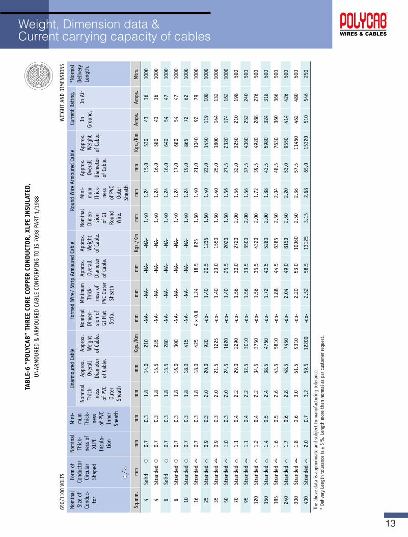
Weight, Dimension data & Current carrying capacity of cables
TABL
E-6
“POL
YCAB
” TH
REE
CORE
COP
PER
CON
DUCT
OR, X
LPE
INSU
LATE
D,UNARMOURED&ARMOUREDCABLECONFORMINGTOIS7098PART-1/1988
650/1100VOLTS
WEIGHTANDDIMENSIONS
Nom
inal
Si
ze o
f Co
nduc
-to
r
Form
of
Cond
ucto
r Ci
rcul
ar
Shap
ed
Nom
inal
Th
ick-
ness
of
XLPE
In
sula
-tio
n
Min
i-m
um
Thic
k-ne
ss
of P
VC
Inne
r Sh
eath
Unar
mou
red
Cabl
eFormedWire/StripArmouredCable
Roun
d W
ire A
rmou
red
Cabl
eCu
rrent
Rat
ing.
*Nor
mal
De
liver
y Le
ngth
. No
min
al
Thic
k-ne
ss
of P
VC
Oute
r Sh
eath
Appr
ox.
Over
all
Diam
eter
of
Cab
le.
Appr
ox.
Wei
ght
of C
able
.
Nom
inal
Di
men
-sio
n of
GI
Fla
t St
rip.
Min
imum
Th
ick-
ness
of
PVC
Oute
r Sh
eath
Appr
ox.
Over
all
Diam
eter
of
Cab
le.
Appr
ox.
Wei
ght
of C
able
.
Nom
inal
Di
men
-sio
n of
GI
Roun
d W
ire.
Min
i-m
um
Thic
k-ne
ss
of P
VC
Oute
r Sh
eath
Appr
ox.
Over
all
Diam
eter
of
Cab
le.
Appr
ox.
Wei
ght
of C
able
.
In
Grou
nd.
In A
ir
Sq.m
m.
mm
mm
mm
mm
mm
Kgs./Km
mm
mm
mm
Kgs./Km
mm
mm
mm
Kgs./Km
Amps
.Am
ps.
Mtr
s.
4So
lid0.
70.
31.
814
.021
0-N
A--N
A--N
A--N
A-1.
401.
2415
.053
043
3610
00
4St
rand
ed
0.7
0.3
1.8
15.5
235
-NA-
-NA-
-NA-
-NA-
1.40
1.24
16.0
580
4336
1000
6So
lid0.
70.
31.
815
.528
0-N
A--N
A--N
A--N
A-1.
401.
2416
.064
054
4710
00
6St
rand
ed
0.7
0.3
1.8
16.0
300
-NA-
-NA-
-NA-
-NA-
1.40
1.24
17.0
680
5447
1000
10St
rand
ed
0.7
0.3
1.8
18.0
415
-NA-
-NA-
-NA-
-NA-
1.40
1.24
19.0
865
7262
1000
16St
rand
ed
0.7
0.3
1.8
18.0
425
4 x
0.8
1.24
18.5
825
1.60
1.40
21.0
1040
9279
1000
25St
rand
ed
0.9
0.3
2.0
20.0
920
-do-
1.40
20.5
1235
1.60
1.40
23.0
1450
119
108
1000
35St
rand
ed
0.9
0.3
2.0
21.5
1225
-do-
1.40
23.0
1550
1.60
1.40
25.0
1800
144
132
1000
50St
rand
ed
1.0
0.3
2.0
24.5
1620
-do-
1.40
25.5
2020
1.60
1.56
27.5
2320
174
162
1000
70St
rand
ed
1.1
0.4
2.2
29.0
2290
-do-
1.56
30.0
2720
2.00
1.56
32.0
3250
210
198
500
95St
rand
ed
1.1
0.4
2.2
32.5
3010
-do-
1.56
33.5
3500
2.00
1.56
37.5
4060
252
240
500
120
Stra
nded
1.
20.
42.
234
.537
50-d
o-1.
5635
.543
202.
001.
7239
.549
2028
827
650
0
150
Stra
nded
1.
40.
52.
438
.547
60-d
o-1.
7240
.552
802.
001.
8843
.559
8032
431
850
0
185
Stra
nded
1.
60.
52.
643
.558
10-d
o-1.
8844
.563
852.
502.
0448
.576
3036
036
650
0
240
Stra
nded
1.
70.
62.
848
.574
50-d
o-2.
0449
.081
502.
502.
2053
.095
5041
442
650
0
300
Stra
nded
1.
80.
63.
051
.593
10-d
o-2.
2053
.010
060
2.50
2.36
57.5
1146
046
248
050
0
400
Stra
nded
2.
00.
73.
259
.512
200
-do-
2.52
58.5
1312
53.
152.
6865
.015
320
510
546
250
Theabovedataisapproximateandsubjecttomanufacturingtolerance.
* De
liver
y Le
ngth
tole
ranc
e is
± 5
%. L
engt
h m
ore
than
nor
mal
as
per c
usto
mer
requ
est.
14
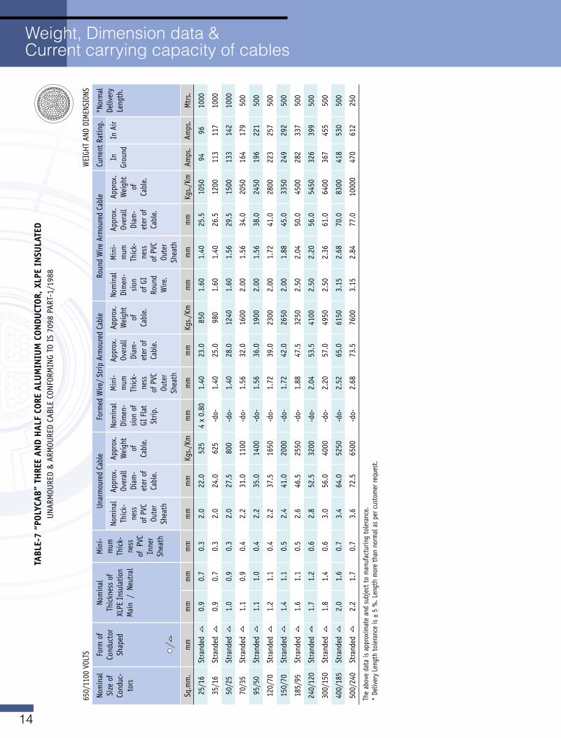
TABL
E-7
“POL
YCAB
” TH
REE
AND
HAL
F CO
RE A
LUM
INIU
M C
ONDU
CTOR
, XLP
E IN
SULA
TED
UNARMOURED&ARMOUREDCABLECONFORMINGTOIS7098PART-1/1988
650/1100VOLTS
WEIGHTANDDIMENSIONS
Nom
inal
Si
ze o
f Co
nduc
-to
rs
Form
of
Cond
ucto
r Sh
aped
Nom
inal
Th
ickn
ess
of
XLPE
Ins
ulat
ion
Main/Neutral
Min
i-m
um
Thic
k-ne
ss
of P
VC
Inne
r Sh
eath
Unar
mou
red
Cabl
eFormedWire/StripArmouredCable
Roun
d W
ire A
rmou
red
Cabl
eCu
rrent
Rat
ing.
*Nor
mal
De
liver
y Le
ngth
. No
min
al
Thic
k-ne
ss
of P
VC
Oute
r Sh
eath
Appr
ox.
Over
all
Diam
-et
er o
f Ca
ble.
Appr
ox.
Wei
ght
of
Cabl
e.
Nom
inal
Di
men
-sio
n of
GI
Fla
t St
rip.
Min
i-m
um
Thic
k-ne
ss
of P
VC
Oute
r Sh
eath
Appr
ox.
Over
all
Diam
-et
er o
f Ca
ble.
Appr
ox.
Wei
ght
of
Cabl
e.
Nom
inal
Di
men
-sio
n of
GI
Roun
d W
ire.
Min
i-m
um
Thic
k-ne
ss
of P
VC
Oute
r Sh
eath
Appr
ox.
Over
all
Diam
-et
er o
f Ca
ble.
Appr
ox.
Wei
ght
of
Cabl
e.
In
Grou
ndIn
Air
Sq.m
m.
mm
mm
mm
mm
mm
mm
Kgs./Km
mm
mm
mm
Kgs./Km
mm
mm
mm
Kgs./Km
Amps
.Am
ps.
Mtr
s.
25/16
Stra
nded
0.
90.
70.
32.
022
.052
54
x 0.
801.
4023
.085
01.
601.
4025
.510
5094
9610
00
35/16
Stra
nded
0.
90.
70.
32.
024
.062
5-d
o-1.
4025
.098
01.
601.
4026
.512
0011
311
710
00
50/25
Stra
nded
1.
00.
90.
32.
027
.580
0-d
o-1.
4028
.012
401.
601.
5629
.515
0013
314
210
00
70/35
Stra
nded
1.
10.
90.
42.
231
.011
00-d
o-1.
5632
.016
002.
001.
5634
.020
5016
417
950
0
95/50
Stra
nded
1.
11.
00.
42.
235
.014
00-d
o-1.
5636
.019
002.
001.
5638
.024
5019
622
150
0
120/70
Stra
nded
1.
21.
10.
42.
237
.516
50-d
o-1.
7239
.023
002.
001.
7241
.028
0022
325
750
0
150/70
Stra
nded
1.
41.
10.
52.
441
.020
00-d
o-1.
7242
.026
502.
001.
8845
.033
5024
929
250
0
185/95
Stra
nded
1.
61.
10.
52.
646
.525
50-d
o-1.
8847
.532
502.
502.
0450
.045
0028
233
750
0
240/120
Stra
nded
1.
71.
20.
62.
852
.532
00-d
o-2.
0453
.541
002.
502.
2056
.054
5032
639
950
0
300/150
Stra
nded
1.
81.
40.
63.
056
.040
00-d
o-2.
2057
.049
502.
502.
3661
.064
0036
745
550
0
400/185
Stra
nded
2.
01.
60.
73.
464
.052
50-d
o-2.
5265
.061
503.
152.
6870
.083
0041
853
050
0
500/240
Stra
nded
2.
21.
70.
73.
672
.565
00-d
o-2.
6873
.576
003.
152.
8477
.010
000
470
612
250
Theabovedataisapproximateandsubjecttomanufacturingtolerance.
* De
liver
y Le
ngth
tole
ranc
e is
± 5
%. L
engt
h m
ore
than
nor
mal
as
per c
usto
mer
requ
est.
Weight, Dimension data & Current carrying capacity of cables
15
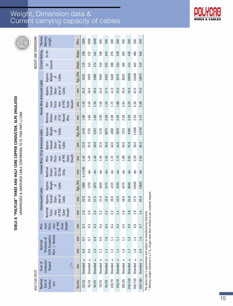
TABL
E-8
“POL
YCAB
” TH
REE
AND
HAL
F CO
RE C
OPPE
R CO
NDU
CTOR
, XLP
E IN
SULA
TED
UNARMOURED&ARMOUREDCABLECONFORMINGTOIS7098PART-1/1988
650/1100VOLTS
WEIGHTANDDIMENSIONS
Nom
inal
Si
ze o
f Co
nduc
-to
rs
Form
of
Cond
ucto
r Sh
aped
Nom
inal
Th
ickn
ess
of
XLPE
Ins
ulat
ion
Main/Neutral
Min
i-m
um
Thic
k-ne
ss
of P
VC
Inne
r Sh
eath
Unar
mou
red
Cabl
eFormedWire/StripArmouredCable
Roun
d W
ire A
rmou
red
Cabl
eCu
rrent
Rat
ing.
*Nor
mal
De
liver
y Le
ngth
. No
min
al
Thic
k-ne
ss
of P
VC
Oute
r Sh
eath
Appr
ox.
Over
all
Diam
-et
er o
f Ca
ble.
Appr
ox.
Wei
ght
of
Cabl
e.
Nom
inal
Di
men
-sio
n of
GI
Fla
t St
rip.
Min
i-m
um
Thic
k-ne
ss
of P
VC
Oute
r Sh
eath
Appr
ox.
Over
all
Diam
-et
er o
f Ca
ble.
Appr
ox.
Wei
ght
of
Cabl
e.
Nom
inal
Di
men
-sio
n of
GI
Roun
d W
ire.
Min
i-m
um
Thic
k-ne
ss
of P
VC
Oute
r Sh
eath
Appr
ox.
Over
all
Diam
-et
er o
f Ca
ble.
Appr
ox.
Wei
ght
of
Cabl
e.
In
Grou
ndIn
Air
Sq.m
m.
mm
mm
mm
mm
mm
mm
Kgs./Km
mm
mm
mm
Kgs./Km
mm
mm
mm
Kgs./Km
Amps
.Am
ps.
Mtr
s.
25/16
Stra
nded
0.
90.
70.
32.
022
.010
804
x 0.
801.
4023
.014
101.
601.
4024
.016
1011
910
810
00
35/16
Stra
nded
0.
90.
70.
32.
024
.013
70-d
o-1.
4025
.017
251.
601.
4026
.019
5014
413
210
00
50/25
Stra
nded
1.
00.
90.
32.
027
.518
75-d
o-1.
4028
.023
251.
601.
5629
.025
8017
416
210
00
70/35
Stra
nded
1.
10.
90.
42.
231
.026
20-d
o-1.
5632
.031
102.
001.
5634
.035
6021
019
850
0
95/50
Stra
nded
1.
11.
00.
42.
235
.034
75-d
o-1.
5636
.089
752.
001.
5637
.545
2525
224
050
0
120/70
Stra
nded
1.
21.
10.
42.
239
.043
15-d
o-1.
7240
.049
602.
001.
7241
.054
6028
827
650
0
150/70
Stra
nded
1.
41.
10.
52.
443
.052
20-d
o-1.
7244
.058
702.
001.
8845
.065
7032
431
850
0
185/95
Stra
nded
1.
61.
10.
52.
648
.065
75-d
o-1.
8850
.072
752.
502.
0450
.085
2036
036
650
0
240/120
Stra
nded
1.
71.
20.
62.
854
.084
00-d
o-2.
0455
.093
002.
502.
2056
.010
650
414
426
500
300/150
Stra
nded
1.
81.
40.
63.
057
.010
500
-do-
2.20
58.0
1150
02.
502.
3661
.012
400
462
480
500
400/185
Stra
nded
2.
01.
60.
73.
465
.013
820
-do-
2.52
66.0
1472
03.
152.
6870
.016
875
510
546
250
Theabovedataisapproximateandsubjecttomanufacturingtolerance.
* De
liver
y Le
ngth
tole
ranc
e is
± 5
%. L
engt
h m
ore
than
nor
mal
as
per c
usto
mer
requ
est.
Weight, Dimension data & Current carrying capacity of cables
16
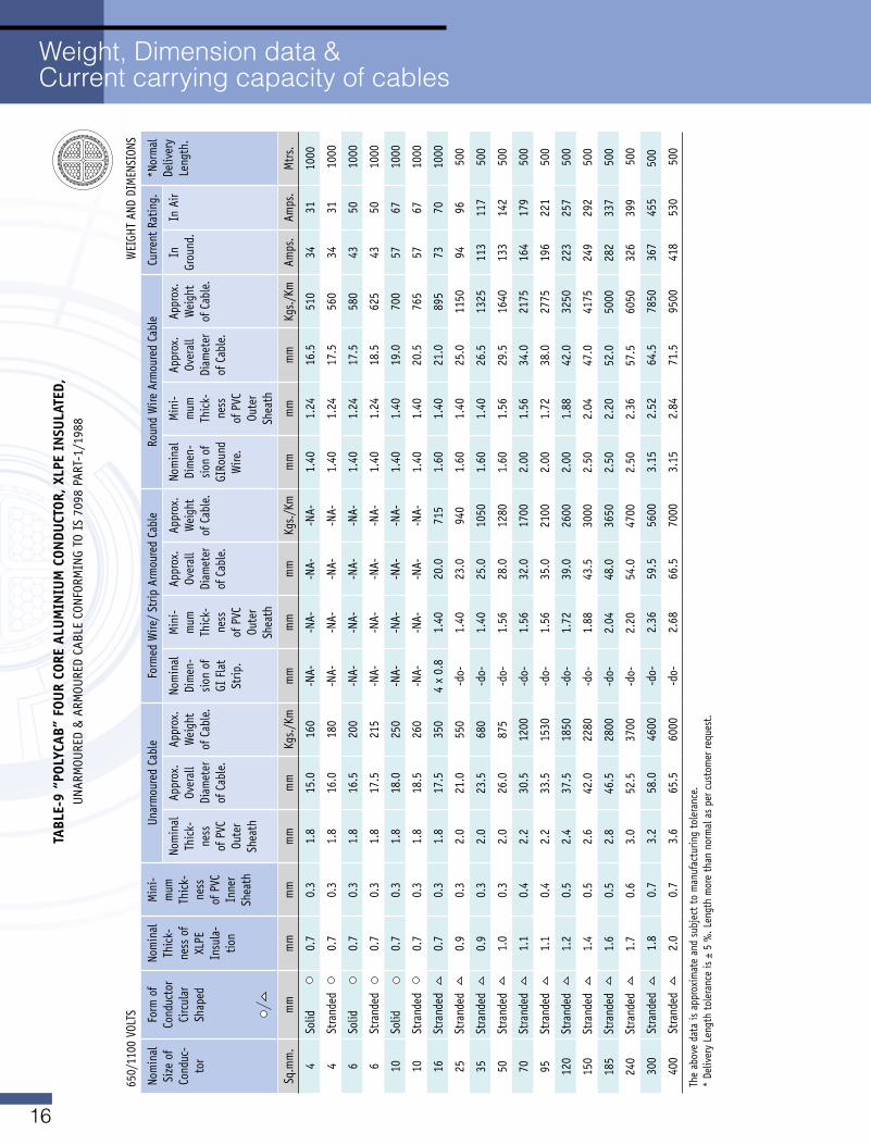
Weight, Dimension data & Current carrying capacity of cables
TABL
E-9
“POL
YCAB
” FO
UR
CORE
ALU
MIN
IUM
CON
DUCT
OR, X
LPE
INSU
LATE
D,UNARMOURED&ARMOUREDCABLECONFORMINGTOIS7098PART-1/1988
650/1100VOLTS
WEIGHTANDDIMENSIONS
Nom
inal
Si
ze o
f Co
nduc
-to
r
Form
of
Cond
ucto
r Ci
rcul
ar
Shap
ed
Nom
inal
Th
ick-
ness
of
XLPE
In
sula
-tio
n
Min
i-m
um
Thic
k-ne
ss
of P
VC
Inne
r Sh
eath
Unar
mou
red
Cabl
eFormedWire/StripArmouredCable
Roun
d W
ire A
rmou
red
Cabl
eCu
rrent
Rat
ing.
*Nor
mal
De
liver
y Le
ngth
. No
min
al
Thic
k-ne
ss
of P
VC
Oute
r Sh
eath
Appr
ox.
Over
all
Diam
eter
of
Cab
le.
Appr
ox.
Wei
ght
of C
able
.
Nom
inal
Di
men
-sio
n of
GI
Fla
t St
rip.
Min
i-m
um
Thic
k-ne
ss
of P
VC
Oute
r Sh
eath
Appr
ox.
Over
all
Diam
eter
of
Cab
le.
Appr
ox.
Wei
ght
of C
able
.
Nom
inal
Di
men
-sio
n of
GI
Roun
d W
ire.
Min
i-m
um
Thic
k-ne
ss
of P
VC
Oute
r Sh
eath
Appr
ox.
Over
all
Diam
eter
of
Cab
le.
Appr
ox.
Wei
ght
of C
able
.
In
Grou
nd.
In A
ir
Sq.m
m.
mm
mm
mm
mm
mm
Kgs./Km
mm
mm
mm
Kgs./Km
mm
mm
mm
Kgs./Km
Amps
.Am
ps.
Mtr
s.
4So
lid0.
70.
31.
815
.016
0-N
A--N
A--N
A--N
A-1.
401.
2416
.551
034
3110
00
4St
rand
ed
0.7
0.3
1.8
16.0
180
-NA-
-NA-
-NA-
-NA-
1.40
1.24
17.5
560
3431
100
0
6So
lid0.
70.
31.
816
.520
0-N
A--N
A--N
A--N
A-1.
401.
2417
.558
043
50 1
000
6St
rand
ed
0.7
0.3
1.8
17.5
215
-NA-
-NA-
-NA-
-NA-
1.40
1.24
18.5
625
4350
100
0
10So
lid0.
70.
31.
818
.025
0-N
A--N
A--N
A--N
A-1.
401.
4019
.070
057
67 1
000
10St
rand
ed
0.7
0.3
1.8
18.5
260
-NA-
-NA-
-NA-
-NA-
1.40
1.40
20.5
765
5767
100
0
16St
rand
ed
0.7
0.3
1.8
17.5
350
4 x
0.8
1.40
20.0
715
1.60
1.40
21.0
895
7370
100
0
25St
rand
ed
0.9
0.3
2.0
21.0
550
-do-
1.40
23.0
940
1.60
1.40
25.0
1150
9496
500
35St
rand
ed
0.9
0.3
2.0
23.5
680
-do-
1.40
25.0
1050
1.60
1.40
26.5
1325
113
117
500
50St
rand
ed
1.0
0.3
2.0
26.0
875
-do-
1.56
28.0
1280
1.60
1.56
29.5
1640
133
142
500
70St
rand
ed
1.1
0.4
2.2
30.5
1200
-do-
1.56
32.0
1700
2.00
1.56
34.0
2175
164
179
500
95St
rand
ed
1.1
0.4
2.2
33.5
1530
-do-
1.56
35.0
2100
2.00
1.72
38.0
2775
196
221
500
120
Stra
nded
1.
20.
52.
437
.518
50-d
o-1.
7239
.026
002.
001.
8842
.032
5022
325
7 5
00
150
Stra
nded
1.
40.
52.
642
.022
80-d
o-1.
8843
.530
002.
502.
0447
.041
7524
929
2 5
00
185
Stra
nded
1.
60.
52.
846
.528
00-d
o-2.
0448
.036
502.
502.
2052
.050
0028
233
7 5
00
240
Stra
nded
1.
70.
63.
052
.537
00-d
o-2.
2054
.047
002.
502.
3657
.560
5032
639
9 5
00
300
Stra
nded
1.
80.
73.
258
.046
00-d
o-2.
3659
.556
003.
152.
5264
.578
5036
745
550
0
400
Stra
nded
2.
00.
73.
665
.560
00-d
o-2.
6866
.570
003.
152.
8471
.595
0041
853
0 5
00
Theabovedataisapproximateandsubjecttomanufacturingtolerance.
* De
liver
y Le
ngth
tole
ranc
e is
± 5
%. L
engt
h m
ore
than
nor
mal
as
per c
usto
mer
requ
est.
17
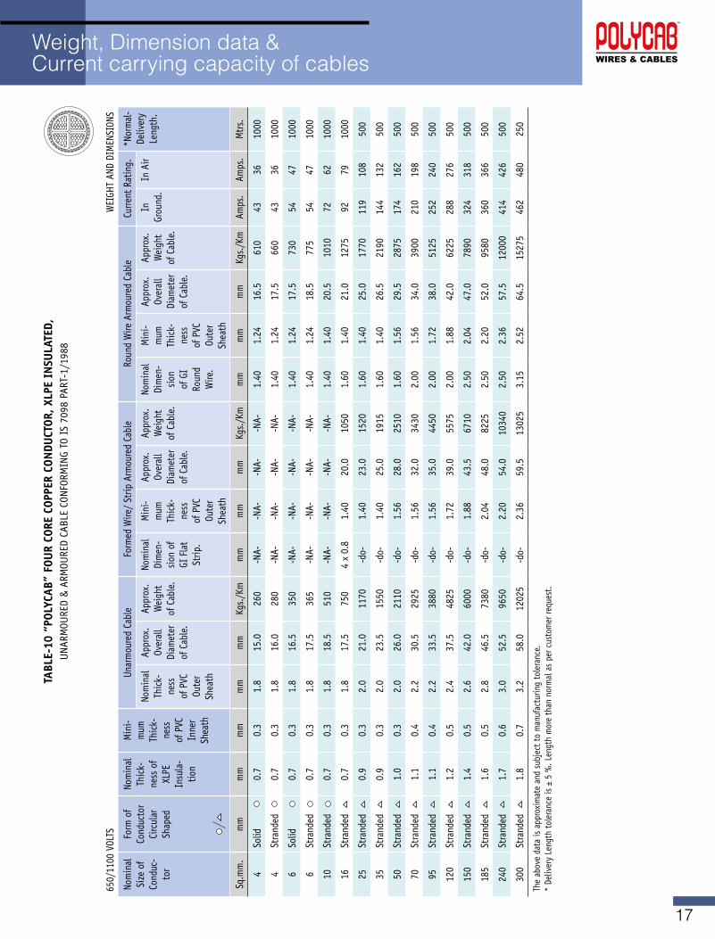
Weight, Dimension data & Current carrying capacity of cables
TABL
E-10
“PO
LYCA
B” F
OUR
CORE
COP
PER
CON
DUCT
OR, X
LPE
INSU
LATE
D,UNARMOURED&ARMOUREDCABLECONFORMINGTOIS7098PART-1/1988
650/1100VOLTS
WEIGHTANDDIMENSIONS
Nom
inal
Si
ze o
f Co
nduc
-to
r
Form
of
Cond
ucto
r Ci
rcul
ar
Shap
ed
Nom
inal
Th
ick-
ness
of
XLPE
In
sula
-tio
n
Min
i-m
um
Thic
k-ne
ss
of P
VC
Inne
r Sh
eath
Unar
mou
red
Cabl
eFormedWire/StripArmouredCable
Roun
d W
ire A
rmou
red
Cabl
eCu
rrent
Rat
ing.
*Nor
mal
-De
liver
y Le
ngth
. No
min
al
Thic
k-ne
ss
of P
VC
Oute
r Sh
eath
Appr
ox.
Over
all
Diam
eter
of
Cab
le.
Appr
ox.
Wei
ght
of C
able
.
Nom
inal
Di
men
-sio
n of
GI
Fla
t St
rip.
Min
i-m
um
Thic
k-ne
ss
of P
VC
Oute
r Sh
eath
Appr
ox.
Over
all
Diam
eter
of
Cab
le.
Appr
ox.
Wei
ght
of C
able
.
Nom
inal
Di
men
-sio
n of
GI
Roun
d W
ire.
Min
i-m
um
Thic
k-ne
ss
of P
VC
Oute
r Sh
eath
Appr
ox.
Over
all
Diam
eter
of
Cab
le.
Appr
ox.
Wei
ght
of C
able
.
In
Grou
nd.
In A
ir
Sq.m
m.
mm
mm
mm
mm
mm
Kgs./Km
mm
mm
mm
Kgs./Km
mm
mm
mm
Kgs./Km
Amps
.Am
ps.
Mtr
s.
4So
lid0.
70.
31.
815
.026
0-N
A--N
A--N
A--N
A-1.
401.
2416
.561
043
3610
00
4St
rand
ed
0.7
0.3
1.8
16.0
280
-NA-
-NA-
-NA-
-NA-
1.40
1.24
17.5
660
4336
1000
6So
lid0.
70.
31.
816
.535
0-N
A--N
A--N
A--N
A-1.
401.
2417
.573
054
4710
00
6St
rand
ed
0.7
0.3
1.8
17.5
365
-NA-
-NA-
-NA-
-NA-
1.40
1.24
18.5
775
5447
1000
10St
rand
ed
0.7
0.3
1.8
18.5
510
-NA-
-NA-
-NA-
-NA-
1.40
1.40
20.5
1010
7262
1000
16St
rand
ed
0.7
0.3
1.8
17.5
750
4 x
0.8
1.40
20.0
1050
1.60
1.40
21.0
1275
9279
1000
25St
rand
ed
0.9
0.3
2.0
21.0
1170
-do-
1.40
23.0
1520
1.60
1.40
25.0
1770
119
108
500
35St
rand
ed
0.9
0.3
2.0
23.5
1550
-do-
1.40
25.0
1915
1.60
1.40
26.5
2190
144
132
500
50St
rand
ed
1.0
0.3
2.0
26.0
2110
-do-
1.56
28.0
2510
1.60
1.56
29.5
2875
174
162
500
70St
rand
ed
1.1
0.4
2.2
30.5
2925
-do-
1.56
32.0
3430
2.00
1.56
34.0
3900
210
198
500
95St
rand
ed
1.1
0.4
2.2
33.5
3880
-do-
1.56
35.0
4450
2.00
1.72
38.0
5125
252
240
500
120
Stra
nded
1.
20.
52.
437
.548
25-d
o-1.
7239
.055
752.
001.
8842
.062
2528
827
650
0
150
Stra
nded
1.
40.
52.
642
.060
00-d
o-1.
8843
.567
102.
502.
0447
.078
9032
431
850
0
185
Stra
nded
1.
60.
52.
846
.573
80-d
o-2.
0448
.082
252.
502.
2052
.095
8036
036
650
0
240
Stra
nded
1.
70.
63.
052
.596
50-d
o-2.
2054
.010
340
2.50
2.36
57.5
1200
041
442
650
0
300
Stra
nded
1.
80.
73.
258
.012
025
-do-
2.36
59.5
1302
53.
152.
5264
.515
275
462
480
250
Theabovedataisapproximateandsubjecttomanufacturingtolerance.
* De
liver
y Le
ngth
tole
ranc
e is
± 5
%. L
engt
h m
ore
than
nor
mal
as
per c
usto
mer
requ
est.
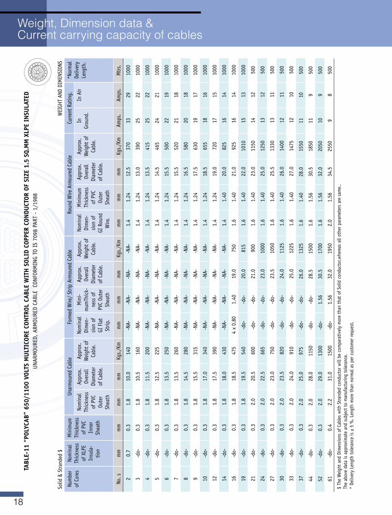
18
Weight, Dimension data & Current carrying capacity of cables
TABL
E-11
“PO
LYCA
B” 6
50/1
100
vOLT
S M
ULT
ICOR
E CO
NTR
OL C
ABLE
WIT
H S
OLID
COP
PER
CON
DUCT
OR O
F SI
ZE 1
.5 S
q.M
M X
LPE
INSU
LATE
DUNARMOURED,ARMOUREDCABLECONFORMINGTOIS7098PART-1/1988
Solid
& S
trand
ed $
W
EIGH
T AN
D DI
MEN
SION
S
Num
ber
of C
ores
Nom
inal
Th
ickn
ess
of X
LPE
Insu
la-
tion
Min
imum
Th
ickn
ess
of P
VC
Inne
r Sh
eath
Unar
mou
red
Cabl
eFormedWire/StripArmouredCable
Roun
d W
ire A
rmou
red
Cabl
eCu
rrent
Rat
ing.
*Nor
mal
De
liver
y Le
ngth
. No
min
al
Thic
knes
s of
PVC
Ou
ter
Shea
th
Appr
ox.
Over
all
Diam
eter
of
Cab
le.
Appr
ox.
Wei
ght o
f Ca
ble.
Nom
inal
Di
men
-sio
n of
GI
Fla
t St
rip.
Min
i-m
umTh
ick-
ness
of
PVC
Oute
r Sh
eath
Appr
ox.
Over
all
Diam
eter
of
Cab
le.
Appr
ox.
Wei
ght o
f Ca
ble.
Nom
inal
Di
men
-sio
n of
GI
Rou
nd
Wire
.
Min
imum
Th
ickn
ess
of P
VC
Oute
r Sh
eath
Appr
ox.
Over
all
Diam
eter
of
Cab
le.
Appr
ox.
Wei
ght o
f Ca
ble.
In
Grou
nd.
In A
ir
No. s
mm
mm
mm
mm
Kgs./Km
mm
mm
mm
Kgs./Km
mm
mm
mm
Kgs./Km
Amps
.Am
ps.
Mtr
s.
20.
70.
31.
810
.014
0-N
A--N
A--N
A--N
A-1.
41.
2412
.537
033
2910
00
3-d
o-0.
31.
810
.516
0-N
A--N
A--N
A--N
A-1.
41.
2413
.039
025
2210
00
4-d
o-0.
31.
811
.520
0-N
A--N
A--N
A--N
A-1.
41.
2413
.541
525
2210
00
5-d
o-0.
31.
812
.522
5-N
A--N
A--N
A--N
A-1.
41.
2414
.546
524
2110
00
6-d
o-0.
31.
813
.525
0-N
A--N
A--N
A--N
A-1.
41.
2415
.550
022
1910
00
7-d
o-0.
31.
813
.526
0-N
A--N
A--N
A--N
A-1.
41.
2415
.552
021
1810
00
8-d
o-0.
31.
814
.528
0-N
A--N
A--N
A--N
A-1.
41.
2416
.558
020
1810
00
9-d
o-0.
31.
815
.531
5-N
A--N
A--N
A--N
A-1.
41.
2417
.563
019
1710
00
10-d
o-0.
31.
817
.034
0-N
A--N
A--N
A--N
A-1.
41.
2418
.565
518
1610
00
12-d
o-0.
31.
817
.539
0-N
A--N
A--N
A--N
A-1.
41.
2419
.072
017
1510
00
14-d
o-0.
31.
818
.043
0-N
A--N
A--N
A--N
A-1.
41.
4020
.082
516
1410
00
16-d
o-0.
31.
818
.547
54
x 0.
801.
4019
.075
01.
61.
4021
.092
516
1410
00
19-d
o-0.
31.
819
.554
0-d
o-
-do-
20.0
815
1.6
1.40
22.0
1010
1513
1000
21-d
o-0.
32.
020
.560
0-d
o-
-do-
21.0
900
1.6
1.40
23.0
1150
1412
500
24-d
o-0.
32.
022
.566
5-d
o-
-do-
23.0
1000
1.6
1.40
25.0
1250
1312
500
27-d
o-0.
32.
023
.075
0-d
o-
-do-
23.5
1050
1.6
1.40
25.5
1330
1311
500
30-d
o-0.
32.
023
.582
0-d
o-
-do-
24.0
1125
1.6
1.40
26.0
1400
1211
500
33-d
o-0.
32.
024
.091
0-d
o--d
o-25
.012
251.
61.
4027
.014
7512
1050
0
37-d
o-0.
32.
025
.097
5-d
o--d
o-26
.013
251.
61.
4028
.015
5011
1050
0
44-d
o-0.
32.
028
.011
50-d
o--d
o-28
.515
001.
61.
5630
.518
5011
950
0
52-d
o-0.
32.
029
.013
00-d
o-1.
5630
.517
001.
61.
5632
.020
5010
950
0
61-d
o-0.
42.
231
.015
00-d
o-1.
5632
.019
502.
01.
5634
.525
509
850
0
$ Th
e W
eigh
t and
Dim
ensio
ns o
f Cab
les
with
Stra
nded
con
duct
or w
ill b
e co
mpa
rativ
ely
mor
e th
an th
at o
f Sol
id c
ondu
ctor
,whe
reas
all
othe
r par
amet
ers
are
sam
e..
Theabovedataisapproximateandsubjecttomanufacturingtolerance.
* De
liver
y Le
ngth
tole
ranc
e is
± 5
%. L
engt
h m
ore
than
nor
mal
as
per c
usto
mer
requ
est.
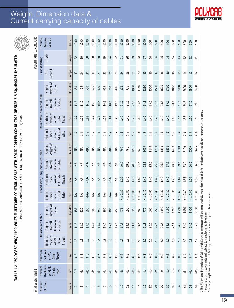
19
Weight, Dimension data & Current carrying capacity of cables
TABL
E-12
“PO
LYCA
B” 6
50/1
100
vOLT
S M
ULT
ICOR
E CO
NTR
OL C
ABLE
WIT
H S
OLID
COP
PER
CON
DUCT
OR O
F SI
ZE 2
.5 S
q.M
MXL
PE I
NSU
LATE
DUNARMOURED,ARMOUREDCABLECONFORMINGTOIS7098PART-1/1988
Solid
& S
trand
ed $
W
EIGH
T AN
D DI
MEN
SION
S
Num
ber
of C
ores
Nom
inal
Th
ickn
ess
of X
LPE
Insu
la-
tion
Min
imum
Th
ickn
ess
of P
VC
Inne
r Sh
eath
Unar
mou
red
Cabl
eFormedWire/StripArmouredCable
Roun
d W
ire A
rmou
red
Cabl
eCu
rrent
Rat
ing.
*Nor
mal
De
liver
y Le
ngth
. No
min
al
Thic
knes
s of
PVC
Ou
ter
Shea
th
Appr
ox.
Over
all
Diam
eter
of
Cab
le.
Appr
ox.
Wei
ght o
f Ca
ble.
Nom
inal
Di
men
-sio
n of
GI
Fla
t St
rip.
Min
imum
Th
ick-
ness
of
PVC
Oute
r Sh
eath
Appr
ox.
Over
all
Diam
eter
of
Cab
le.
Appr
ox.
Wei
ght o
f Ca
ble.
Nom
inal
Di
men
-sio
n of
GI
Rou
nd
Wire
.
Min
imum
Th
ickn
ess
of P
VC
Oute
r Sh
eath
Appr
ox.
Over
all
Diam
eter
of
Cab
le.
Appr
ox.
Wei
ght o
f Ca
ble.
In
Grou
nd.
In A
ir
No. s
mm
mm
mm
mm
Kgs./Km
mm
mm
mm
Kgs./Km
mm
mm
mm
Kgs./Km
Amps
.Am
ps.
Mtr
s.
20.
70.
31.
811
.518
5-N
A--N
A--N
A--N
A-1.
41.
2413
.538
039
3210
00
3-d
o-0.
31.
812
.022
0-N
A--N
A--N
A--N
A-1.
41.
2414
.042
534
3010
00
4-d
o-0.
31.
813
.026
0-N
A--N
A--N
A--N
A-1.
41.
2414
.550
034
3010
00
5-d
o-0.
31.
814
.030
0-N
A--N
A--N
A--N
A-1.
41.
2415
.552
531
2810
00
6-d
o-0.
31.
815
.034
0-N
A--N
A--N
A--N
A-1.
41.
2416
.560
029
2610
00
7-d
o-0.
31.
815
.036
0-N
A--N
A--N
A--N
A-1.
41.
2416
.562
527
2510
00
8-d
o-0.
31.
816
.040
0-N
A--N
A--N
A--N
A-1.
41.
2418
.070
026
2410
00
9-d
o-0.
31.
816
.545
0-N
A--N
A--N
A--N
A-1.
41.
4019
.580
025
2210
00
10-d
o-0.
31.
817
.547
54
x 0.
801.
2419
.070
01.
61.
4021
.087
524
2110
00
12-d
o-0.
31.
818
.055
04
x 0.
801.
4019
.576
01.
61.
4021
.597
522
2010
00
14-d
o-0.
31.
819
.062
54
x 0.
801.
4020
.085
01.
61.
4022
.010
5021
1910
00
16-d
o-0.
32.
020
.568
04
x 0.
801.
4021
.592
01.
61.
4023
.511
6020
1810
00
19-d
o-0.
32.
021
.577
04
x 0.
801.
4022
.510
251.
61.
4024
.512
5019
1710
00
21-d
o-0.
32.
022
.586
04
x 0.
801.
4023
.511
401.
61.
4025
.513
5018
1650
0
24-d
o-0.
32.
024
.595
04
x 0.
801.
4025
.512
501.
61.
4027
.515
0017
1650
0
27-d
o-0.
32.
025
.510
504
x 0.
801.
4026
.513
501.
61.
4028
.516
2516
1650
0
30-d
o-0.
32.
026
.011
504
x 0.
801.
4027
.515
501.
61.
4029
.017
6016
1450
0
33-d
o-0.
32.
027
.012
504
x 0.
801.
4028
.516
301.
61.
5630
.519
5015
1450
0
37-d
o-0.
32.
028
.013
504
x 0.
801.
4029
.517
101.
61.
5631
.520
8015
1350
0
44-d
o-0.
42.
232
.016
504
x 0.
801.
5633
.021
002.
01.
5635
.526
0014
1250
0
52-d
o-0.
42.
233
.519
504
x 0.
801.
5634
.523
502.
01.
5637
.529
0013
1250
0
61-d
o-0.
42.
235
.021
504
x 0.
801.
5636
.026
252.
01.
5639
.034
0012
1150
0
$ Th
e W
eigh
t and
Dim
ensio
ns o
f Cab
les
with
Stra
nded
con
duct
or w
ill b
e co
mpa
rativ
ely
mor
e th
an th
at o
f Sol
id c
ondu
ctor
,whe
reas
all
othe
r par
amet
ers
are
sam
e..
Theabovedataisapproximateandsubjecttomanufacturingtolerance.
* De
liver
y Le
ngth
tole
ranc
e is
± 5
%. L
engt
h m
ore
than
nor
mal
as
per c
usto
mer
requ
est.
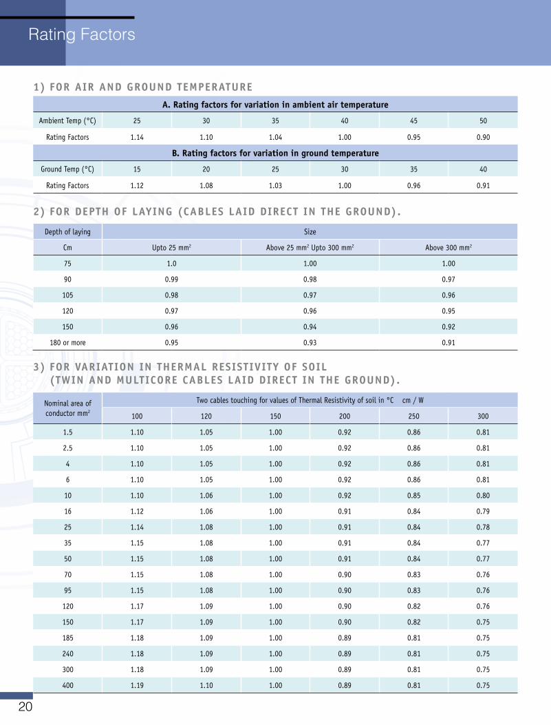
20
1) FOR AIR AND gROUND TEMPERATURE
A. Rating factors for variation in ambient air temperature
Ambient Temp (°C) 25 30 35 40 45 50
Rating Factors 1.14 1.10 1.04 1.00 0.95 0.90
B. Rating factors for variation in ground temperature
Ground Temp (°C) 15 20 25 30 35 40
Rating Factors 1.12 1.08 1.03 1.00 0.96 0.91
2) FOR DEPTH OF LAYINg (CABLES LAID DIRECT IN THE gROUND).
Depth of laying Size
Cm Upto 25 mm2 Above 25 mm2 Upto 300 mm2 Above 300 mm2
75 1.0 1.00 1.00
90 0.99 0.98 0.97
105 0.98 0.97 0.96
120 0.97 0.96 0.95
150 0.96 0.94 0.92
180 or more 0.95 0.93 0.91
3) FOR vARIATION IN THERMAL RESISTIvITY OF SOIL (TWIN AND MULTICORE CABLES LAID DIRECT IN THE gROUND).
Nominal area of conductor mm2
TwocablestouchingforvaluesofThermalResistivityofsoilin°Ccm/W
100 120 150 200 250 300
1.5 1.10 1.05 1.00 0.92 0.86 0.81
2.5 1.10 1.05 1.00 0.92 0.86 0.81
4 1.10 1.05 1.00 0.92 0.86 0.81
6 1.10 1.05 1.00 0.92 0.86 0.81
10 1.10 1.06 1.00 0.92 0.85 0.80
16 1.12 1.06 1.00 0.91 0.84 0.79
25 1.14 1.08 1.00 0.91 0.84 0.78
35 1.15 1.08 1.00 0.91 0.84 0.77
50 1.15 1.08 1.00 0.91 0.84 0.77
70 1.15 1.08 1.00 0.90 0.83 0.76
95 1.15 1.08 1.00 0.90 0.83 0.76
120 1.17 1.09 1.00 0.90 0.82 0.76
150 1.17 1.09 1.00 0.90 0.82 0.75
185 1.18 1.09 1.00 0.89 0.81 0.75
240 1.18 1.09 1.00 0.89 0.81 0.75
300 1.18 1.09 1.00 0.89 0.81 0.75
400 1.19 1.10 1.00 0.89 0.81 0.75
Rating Factors
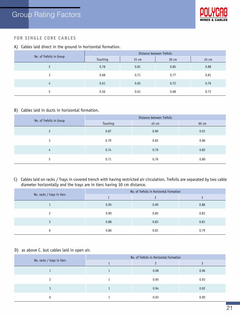
21
Group Rating Factors
FOR SINgLE CORE CABLES
A) Cables laid direct in the ground in horizontal formation.
No. of Trefoils in GroupDistance between Trefoils
Touching 15 cm 30 cm 45 cm
2 0.78 0.81 0.85 0.88
3 0.68 0.71 0.77 0.81
4 0.61 0.65 0.72 0.76
5 0.56 0.61 0.68 0.73
No. of Trefoils in GroupDistance between Trefoils
Touching 45 cm 60 cm
2 0.87 0.90 0.91
3 0.79 0.83 0.86
4 0.74 0.79 0.82
5 0.71 0.76 0.80
B) Cables laid in ducts in horizontal formation.
C) Cableslaidonracks/Traysincoveredtrenchwithhavingrestrictedaircirculation,Trefoilsareseparatedbytwocablediameter horizontally and the trays are in tiers having 30 cm distance.
No.racks/traysintiersNo. of Trefoils in Horizontal Formation
1 2 3
1 0.95 0.90 0.88
2 0.90 0.85 0.83
3 0.88 0.83 0.81
6 0.86 0.81 0.79
D) as above C. but cables laid in open air.
No.racks/traysintiersNo. of Trefoils in Horizontal Formation
1 2 3
1 1 0.98 0.96
2 1 0.95 0.93
3 1 0.94 0.92
6 1 0.93 0.90
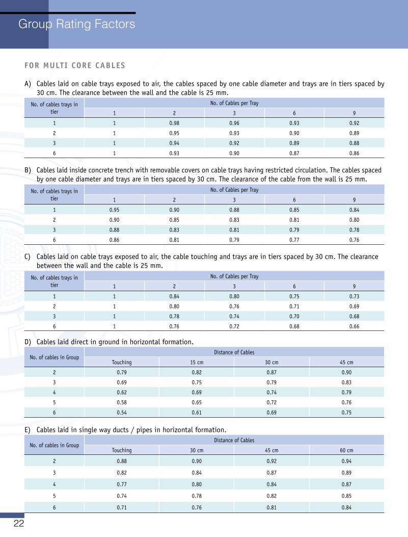
22
FOR MULTI CORE CABLES
A) Cables laid on cable trays exposed to air, the cables spaced by one cable diameter and trays are in tiers spaced by 30 cm. The clearance between the wall and the cable is 25 mm.
No. of cables trays in tier
No. of Cables per Tray
1 2 3 6 9
1 1 0.98 0.96 0.93 0.92
2 1 0.95 0.93 0.90 0.89
3 1 0.94 0.92 0.89 0.88
6 1 0.93 0.90 0.87 0.86
B) Cables laid inside concrete trench with removable covers on cable trays having restricted circulation. The cables spaced by one cable diameter and trays are in tiers spaced by 30 cm. The clearance of the cable from the wall is 25 mm.
No. of cables trays in tier
No. of Cables per Tray
1 2 3 6 9
1 0.95 0.90 0.88 0.85 0.84
2 0.90 0.85 0.83 0.81 0.80
3 0.88 0.83 0.81 0.79 0.78
6 0.86 0.81 0.79 0.77 0.76
C) Cables laid on cable trays exposed to air, the cable touching and trays are in tiers spaced by 30 cm. The clearance between the wall and the cable is 25 mm.
No. of cables trays in tier
No. of Cables per Tray
1 2 3 6 9
1 1 0.84 0.80 0.75 0.73
2 1 0.80 0.76 0.71 0.69
3 1 0.78 0.74 0.70 0.68
6 1 0.76 0.72 0.68 0.66
E) Cables laid in single way ducts/pipesinhorizontalformation.
No. of cables in GroupDistance of Cables
Touching 30 cm 45 cm 60 cm
2 0.88 0.90 0.92 0.94
3 0.82 0.84 0.87 0.89
4 0.77 0.80 0.84 0.87
5 0.74 0.78 0.82 0.85
6 0.71 0.76 0.81 0.84
D) Cables laid direct in ground in horizontal formation.
No. of cables in GroupDistance of Cables
Touching 15 cm 30 cm 45 cm
2 0.79 0.82 0.87 0.90
3 0.69 0.75 0.79 0.83
4 0.62 0.69 0.74 0.79
5 0.58 0.65 0.72 0.76
6 0.54 0.61 0.69 0.75
Group Rating Factors
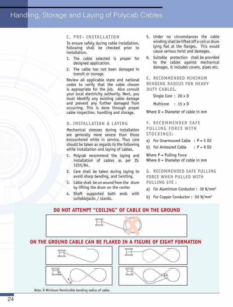
24
DO NOT ATTEMPT “COILINg” OF CABLE ON THE gROUND
ON THE gROUND CABLE CAN BE FLAKED IN A FIgURE OF EIgHT FORMATION
Note: R Minimum Permissible bending radius of cable.
Handling, Storage and Laying of Polycab Cables
C. PRE- INSTALLATIONTo ensure safety during cable installation, following shall be checked prior to installation.1. The cable selected is proper for
designed application.2. The cable has not been damaged in
transit or storage. Review all applicable state and national codes to verify that the cable chosen is appropriate for the job. Also consultyour local electricity authority. Next, you must identify any existing cable damage and prevent any further damaged from occurring. This is done through proper cable inspection, handling and storage.
D. INSTALLATION & LAYINg Mechanical stresses during installation are generally more severe than those encountered while in service. Thus care should be taken as regards to the following while installation and laying of cables.1. Polycab recommend the laying and
installation of cables as per IS: 1255/84.
2. Care shall be taken during laying to avoid sharp bending, and twisting.
3. Cable shall be un wound from the drum by lifting the drum on the center
4. Shaft supported both ends with suitablejacks/stands.
5. Under no circumstances the cable winding shall be lifted off a coil or drum lying flat at the flanges. This would cause serious twist and damages.
6. Suitable protection shall be provided to the cables against mechanical damages, it includes covers, pipes etc.
E. RECOMMENDED MINIMUM BENDINg RADIUS FOR HEAvY DUTY CABLES. Single Core : 20 x D
Multicore : 15 x D
Where D = Diameter of cable in mm
F. RECOMMENDED SAFE PULLINg FORCE WITH STOCKINgS:a) For Unarmoured Cable : P = 5 D2
b) For Armoured Cable : P = 9 D2
Where P = Pulling Force Where D = Diameter of cable in mm
g. RECOMMENDED SAFE PULLINg FORCE WHEN PULLED WITH PULLINg EYE :a) ForAluminiumConductor:30N/mm2
b) ForCopperConductor:50N/mm2