desktop thermal printer user’s manual 2722 2742 3742natmar-nsc.com/titan/s30.pdfuser’s manual...
TRANSCRIPT
User’s Manual No. 980344-001 Rev. A
©2001 Zebra Technologies Corporation
272227423742
DesktopThermal PrinterUser’s Manual
COPYRIGHT NOTICE
This document contains information proprietary to Zebra Technologies Corporation. This docu-ment and the information contained within is copyrighted by Zebra Technologies Corporation andmay not be duplicated in full or in part by any person without written approval from Zebra Technol-ogies Corporation. While every effort has been made to keep the information contained within cur-rent and accurate as of the date of publication, no guarantee is given or implied that the documentis error-free or that it is accurate with regard to any specification. Zebra Technologies Corporationreserves the right to make changes, for the purpose of product improvement, at any time.
TRADEMARKS
LP2722, TLP2722, LP2742, TLP2742 and TLP3742 are service marks and Zebra is a trademarkof Zebra Technologies Corporation. Windows and MS-DOS are registered trademarks of MicrosoftCorp. All other marks are trademarks or registered trademarks of their respective holders.
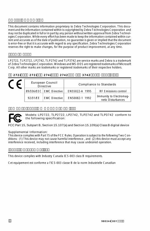
LP2722, TLP2722, LP2742, TLP2742 and TLP3742 Thermal Printers
European CouncilDirective Compliance to Standards
89/336/EEC EMC Directive EN55022-A 1995 RF Emissions control
92/31/EE EMC Directive EN50082-1 1992 Immunity to Electromag-netic Disturbances
FCC - DECLARATION OF CONFORMITY:
Models: LP2722, TLP2722, LP2742, TLP2742 and TLP3742 conform tothe following specification:
FCC Part 15, Subpart B, Section 15.107(a) and Section 15.109(a) Class B digital device
Supplemental Information:This device complies with Part 15 of the FCC Rules. Operation is subject to the following Two Con-ditions: (1) This device may not cause harmful interference , and (2) this device must accept anyinterference received, including interference that may cause undesired operation.
Industry Canada Notice:
This device complies with Industry Canada ICS-003 class B requirements.
Cet equipement est conforme a l’ICS-003 classe B de la norm Industrielle Canadian
ii 980344-001 Rev.A
TABLE OF CONTENTS
Installation and OperationUnpacking Your Printer . . . . . . . . . . . . . . . . . . . . 2Getting To Know Your Printer . . . . . . . . . . . . . . . . . 3Installation . . . . . . . . . . . . . . . . . . . . . . . . . . . 4Attach Power . . . . . . . . . . . . . . . . . . . . . . . . . 4Attach Interface Cable . . . . . . . . . . . . . . . . . . . . . 5Load Media . . . . . . . . . . . . . . . . . . . . . . . . . . 6Before You Load Media in the Printer . . . . . . . . . . . . . 7AutoSense . . . . . . . . . . . . . . . . . . . . . . . . . . . 13Install Software . . . . . . . . . . . . . . . . . . . . . . . . 13Using Fan-Fold Media . . . . . . . . . . . . . . . . . . . . . 14Label Dispenser . . . . . . . . . . . . . . . . . . . . . . . . 15Thermal Transfer Ribbon Loading . . . . . . . . . . . . . . . 18
Appendix A - Troubleshooting . . . . . . . . . . . . . . . . 21Printer Maintenance . . . . . . . . . . . . . . . . . . . . . . 22Printer Configuration Settings . . . . . . . . . . . . . . . . . 23Serial Interface Communication Configuration. . . . . . . . . 24RS-232 Serial Interface Cable Wiring . . . . . . . . . . . . . 24Parallel Interface Cable Wiring . . . . . . . . . . . . . . . . . 25
980344-001 Rev.A iii
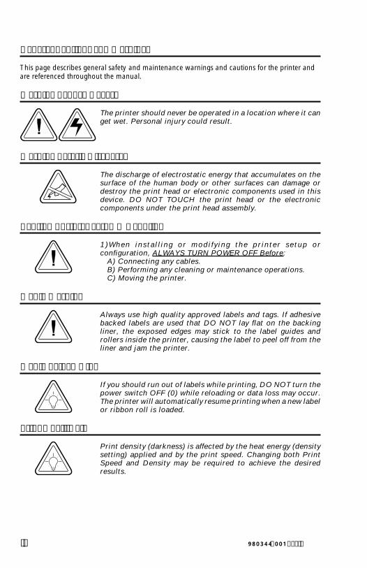
General Cautions and Warnings
This page describes general safety and maintenance warnings and cautions for the printer andare referenced throughout the manual.
Warning - Shock Hazard
The printer should never be operated in a location where it canget wet. Personal injury could result.
Warning - Static Discharge
The discharge of electrostatic energy that accumulates on thesurface of the human body or other surfaces can damage ordestroy the print head or electronic components used in thisdevice. DO NOT TOUCH the print head or the electroniccomponents under the print head assembly.
Caution - Printer Setup & Handling
1)When installing or modifying the printer setup orconfiguration, ALWAYS TURN POWER OFF Before:
A) Connecting any cables.B) Performing any cleaning or maintenance operations.C) Moving the printer.
Media Warning
Always use high quality approved labels and tags. If adhesivebacked labels are used that DO NOT lay flat on the backingliner, the exposed edges may stick to the label guides androllers inside the printer, causing the label to peel off from theliner and jam the printer.
Media Reload Hint
If you should run out of labels while printing, DO NOT turn thepower switch OFF (0) while reloading or data loss may occur.The printer will automatically resume printing when a new labelor ribbon roll is loaded.
Print Quality Tip
Print density (darkness) is affected by the heat energy (densitysetting) applied and by the print speed. Changing both PrintSpeed and Density may be required to achieve the desiredresults.
iv 980344-001 Rev.A

1Installation and Operation
This section provides information on the instal-lation and operation of the printer.
The printer is a low cost, desktop thermal barcode printer. LP models are direct thermal. TLPmodes are thermal transfer and direct thermalprinters. This family of printers is specifically de-signed for printing labels, tags or continuous re-ceipts (with or without bar codes) from aDOS™, Windows™or ASCII-based compatiblecomputer.
980344-001 Rev.A 1
Installation and Operation

Unpacking Your Printer
Installation and Operation
2 980344-001 Rev.A
ForWin
Bar Code
Label Printers
Software and Documentation
105551-006
©2001 Zebra Technologies Corporation
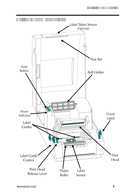
Getting To Know Your Printer
980344-001 Rev.A 3
Installation and Operation
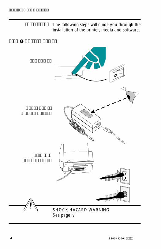
Installation The following steps will guide you through theinstallation of the printer, media and software.
Step � - Attach Power
SHOCK HAZARD WARNINGSee page iv
Installation and Operation
4 980344-001 Rev.A
OXXXXXXXXXXXXXX
XXXXXXXX
XXXXXXXXX
Power OFF
Check PowerModule Voltage
Plug IntoPower Module
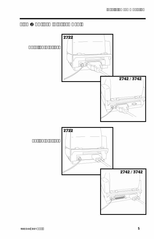
Step � - Attach Interface Cable
980344-001 Rev.A 5
Installation and Operation
Parallel Interface
Serial Interface
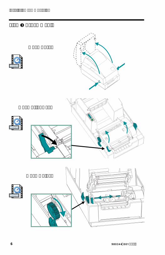
Step � - Load Media
Installation and Operation
6 980344-001 Rev.A
Open Cover
Open Print Head
Open Guides
MOVIE
MOVIE
MOVIE
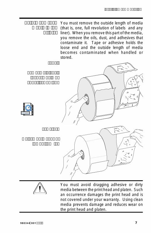
Before You LoadMedia in the
Printer
You must remove the outside length of media(that is, one, full revolution of labels and anyliner). When you remove this part of the media,you remove the oils, dust, and adhesives thatcontaminate it. Tape or adhesive holds theloose end and the outside length of mediabecomes contaminated when handled orstored.
You must avoid dragging adhesive or dirtymedia between the print head and platen. Suchan occurrence damages the print head and isnot covered under your warranty. Using cleanmedia prevents damage and reduces wear onthe print head and platen.
980344-001 Rev.A 7
Installation and Operation
Labels
Remove all labelsthat are held by
adhesives or tape
Tag Stock
Detach both ends ofthe bottom tag
MOVIE
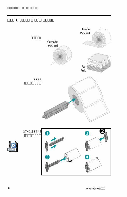
Step � - Load Media (cont.)
Installation and Operation
8 980344-001 Rev.A
2722Install Roll
Media
OUT
OUT
OUT
OUT
OUT
OUT
OUT
OUT
2742 / 3742Install Roll
MOVIE
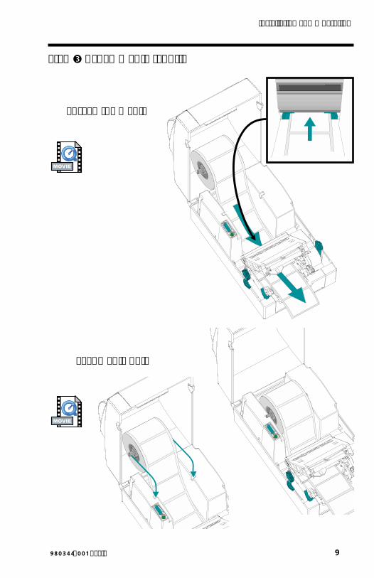
Step � - Load Media (cont.)
980344-001 Rev.A 9
Installation and Operation
Thread the Media
MOVIE
MOVIE
Seat Media Roll
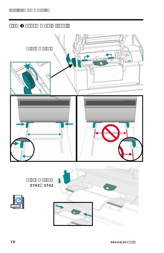
Step � - Load Media (cont.)
Installation and Operation
10 980344-001 Rev.A
Close Guides
Close Guides2742 / 3742
MOVIE
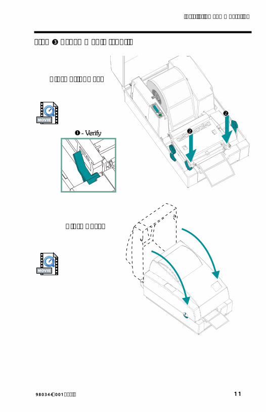
Step � - Load Media (cont.)
980344-001 Rev.A 11
Installation and Operation
Close Cover
MOVIE
MOVIE
Close Print Head
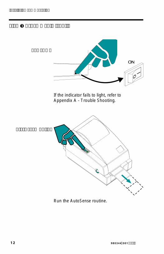
Step � - Load Media (cont.)
If the indicator fails to light, refer toAppendix A - Trouble Shooting.
Run the AutoSense routine.
Installation and Operation
12 980344-001 Rev.A
Press FEED ButtonO
Power ON
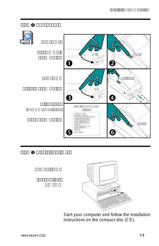
Step � - AutoSense
Step � - Install Software
Start your computer and follow the installationinstructions on the compact disc (CD).
980344-001 Rev.A 13
Installation and Operation
OO
2 UKQ1813 4.00
Serial port : 96,N,8,1
Image buffer size:245K
Fmem:000,0K,019.9K avl
Gmem:000K,0241K avl
E
I8,0,001 rY
S8 D12 R032,000 ZT UN
q0450 Q0800,034
Option:D
11 12 13
now in DUMP
mem:000K,0241K avl
Sample: DUMP ModePrintout
OFF HOLD
RELEASE
PRESS
ON
Power OFF
Press & HoldFEED Button
Power ON
Release FEED Button
Print Status(Dump Mode Printout)
Press FEED Button
Computer ON
Insert PrinterCD ROM
MOVIE
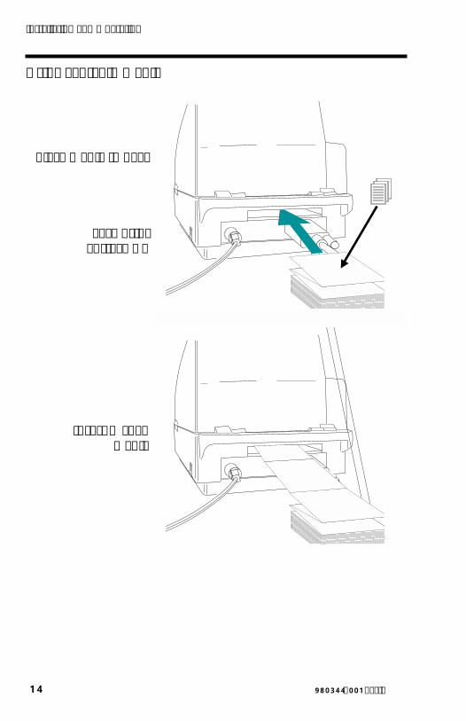
Using Fan-Fold Media
Installation and Operation
14 980344-001 Rev.A
Place Media In Rear
Face PrintSurface UP
Insert & LoadMedia

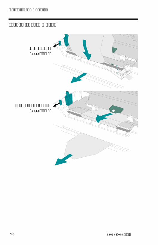
Label Dispenser Printers with an optional label taken sensor candispense a single peeled label. Remove the labelto automatically print the next label.
980344-001 Rev.A 15
Installation and Operation
Expose15CM of Labels
(2722 Shown)
PeelExposed Labels
Cut End ofExposed Liner
(2722 Shown)
Pull Print HeadRelease Lever
(2722 Shown)
Insert LinerUnder Peel Bar
MOVIE
Label Dispense Option
Installation and Operation
16 980344-001 Rev.A
TLP2722
Insert Liner(2742 Shown)
Pull Liner Through(2742 Shown)
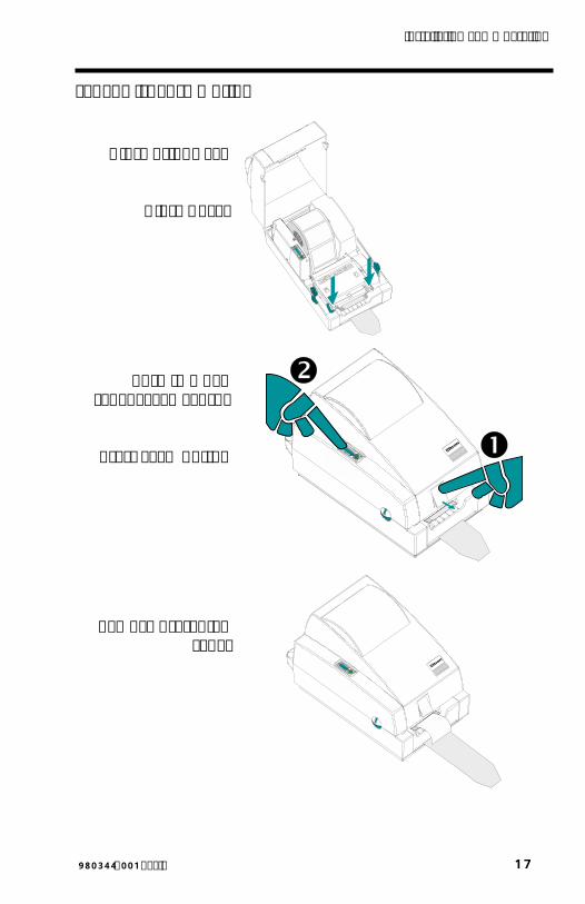
Label Dispense Option
980344-001 Rev.A 17
Installation and Operation
Close Print Head
Close Cover
TLP2722
Push to OpenLabel Taken Sensor
Press FEED Button
TLP2722
Remove PresentedLabel
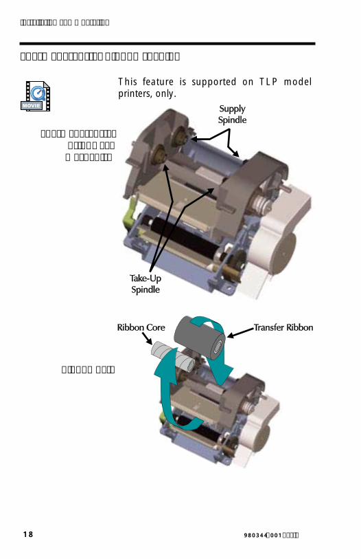
Thermal Transfer Ribbon Loading
This feature is supported on TLP modelprinters, only.
Installation and Operation
18 980344-001 Rev.A
Thermal TransferPrint HeadMechanism
MOVIE
Ribbon Path
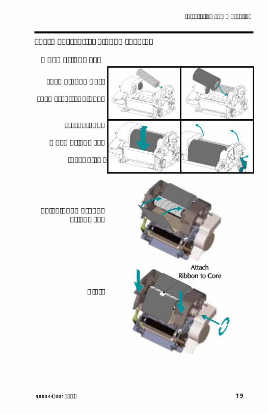
Thermal Transfer Ribbon Loading
Open Print Head
980344-001 Rev.A 19
Installation and Operation
Load Ribbon Core
Load Transfer Ribbon
Start Ribbon
Open Print Head
(Rear View)
Pull Ribbon AroundPrint Head
Close

Installation and Operation
20 980344-001 Rev.A
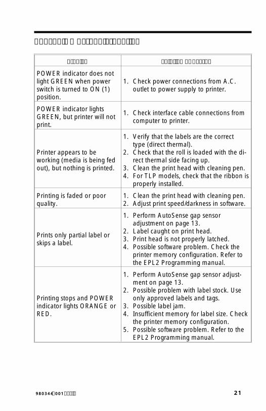
Appendix A - Troubleshooting
Problem Solution or Reason
POWER indicator does notlight GREEN when powerswitch is turned to ON (1)position.
1. Check power connections from A.C.outlet to power supply to printer.
POWER indicator lightsGREEN, but printer will notprint.
1. Check interface cable connections fromcomputer to printer.
Printer appears to beworking (media is being fedout), but nothing is printed.
1. Verify that the labels are the correcttype (direct thermal).
2. Check that the roll is loaded with the di-rect thermal side facing up.
3. Clean the print head with cleaning pen.4. For TLP models, check that the ribbon is
properly installed.
Printing is faded or poorquality.
1. Clean the print head with cleaning pen.2. Adjust print speed/darkness in software.
Prints only partial label orskips a label.
1. Perform AutoSense gap sensoradjustment on page 13.
2. Label caught on print head.3. Print head is not properly latched.4. Possible software problem. Check the
printer memory configuration. Refer tothe EPL2 Programming manual.
Printing stops and POWERindicator lights ORANGE orRED.
1. Perform AutoSense gap sensor adjust-ment on page 13.
2. Possible problem with label stock. Useonly approved labels and tags.
3. Possible label jam.4. Insufficient memory for label size. Check
the printer memory configuration.5. Possible software problem. Refer to the
EPL2 Programming manual.
980344-001 Rev.A 21
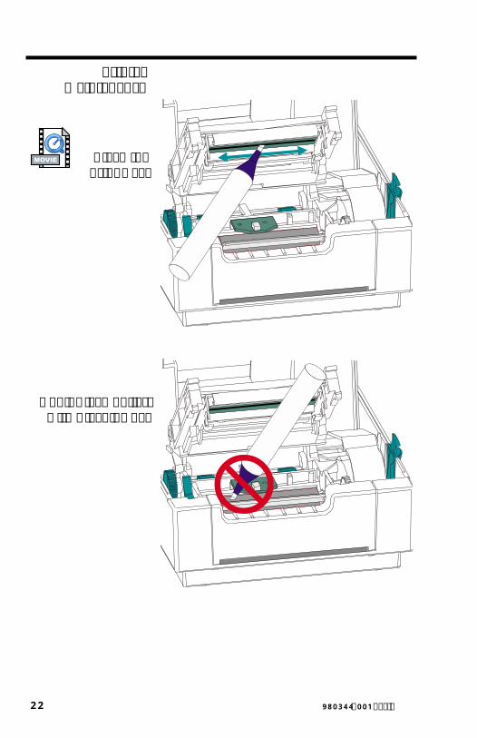
PrinterMaintenance
22 980344-001 Rev.A
Clean thePrint Head
Don’t Clean Rollerswith Cleaning Pen
MOVIE
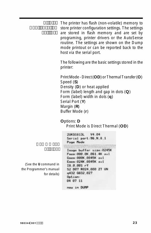
PrinterConfiguration
Settings
The printer has flash (non-volatile) memory tostore printer configuration settings. The settingsare stored in flash memory and are set byprograming, printer drivers or the AutoSenseroutine. The settings are shown on the Dumpmode printout or can be reported back to thehost via the serial port.
The following are the basic settings stored in theprinter:
Print Mode - Direct (OD) or Thermal Transfer (O)Speed (S)Density (D) or heat appliedForm (label) length and gap in dots (Q)Form (label) width in dots (q)Serial Port (Y)Margin (R)Buffer Mode (r)
Options: DPrint Mode is Direct Thermal (OD)
980344-001 Rev.A 23
Dump ModePrintout
(See the U command inthe Programmer’s manual
for details)
Serial InterfaceCommunication
Configuration
The printer’s serial port is configured with theY command for the printer. The printer supportsinterface data rates from 1200 to 38,400 baud.See the programmer's manual for details.
The printer’s serial port default configuration is:9600 baud8 bit data1 stop bitNo parity
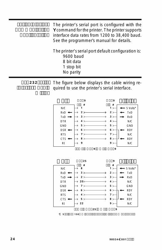
RS-232 SerialInterface Cable
Wiring
The figure below displays the cable wiring re-quired to use the printer’s serial interface.
24 980344-001 Rev.A
N/CRxDTxDDTRGNDDSRRTS
RICTS
PrinterHost112233445566778899
DB-9Pin #
DB-9Pin #
Female DB-9 to Male DB-9
N/CRxDTxDDTRGNDDSRRTS
RICTS
PrinterHost18233242057667485922
DB-25Pin #
DB-9Pin #
Female DB-25 to Male DB-9*+5 volts at 150 mA for external device (e.g. KDU or scanner)
+5 Volts*TxDRxDN/CGNDRDYN/C
N/CRDY
+5 Volts*TxDRxDN/CGNDRDYN/C
N/CRDY
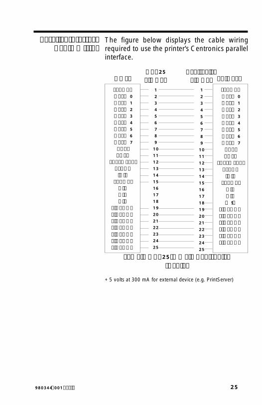
Parallel InterfaceCable Wiring
The figure below displays the cable wiringrequired to use the printer's Centronics parallelinterface.
+5 volts at 300 mA for external device (e.g. PrintServer)
980344-001 Rev.A 25
PRINTERDB-25Pin No.
CentronicsPin No.
Female DB-25 to Male Centronics(Cable)
HOST
STROBEDATA 0DATA 1DATA 2DATA 3DATA 4DATA 5DATA 6DATA 7
ACK/BUSY
PAPER ERR.READY
INITERROR/
N/AN/AN/A
SIG. GNDSIG. GNDSIG. GNDSIG. GNDSIG. GNDSIG. GNDSIG. GND
STROBEDATA 0DATA 1DATA 2DATA 3DATA 4DATA 5DATA 6DATA 7
ACK/BUSY
PAPER ERR.READY
INITERROR/
N/AN/A+5V
SIG. GNDSIG. GNDSIG. GNDSIG. GNDSIG. GNDSIG. GND
123456789
10111213141516171819202122232425
123456789
10111213141516171819202122232425

26 980344-001 Rev.A