designed for residential application kitpl600/pl1000 · sliding gate opener. ... make sure the gate...
TRANSCRIPT

Flashing Light Photocells Transmitter Key Selector Push Button
DESIGNED FOR RESIDENTIAL APPLICATION
KIT PL600/PL1000SLIDING GATE OPENERSPL600/PL1000 electro-mechanical sliding gate openers are designed for residential application.Stylish appearance of the gear motors with innovative design of motor release by the key in case of power failure.Magnetic limit switch and spring limit switch are available for customer’s choice.Over-current function with adjustable setting provides various choices for the gate installation.
The strongest solution for sliding gates
KIT PL600/PL1000
Gear MotorPL600
Gear MotorPL1000
RackPRK-1
SLIDING GATE OPENER


INSTRUCTIONS PL600/PL1000 1
Index
1. Warnings 2
2. Product Description and Applications 32.1 Applications...........................................32.2 Description of The Automation...............32.3 Description of Devices............................32.3.1 PL600/PL1000 Electromechanical Gearmotor..............................................42.3.2 Release Keys.........................................42.3.2.1 Release Gearmotors……………............42.3.3 PH-1 Photocells......................................52.3.4 PR-1 Radio Transmitter..........................52.3.5 PF-1 Flashing Light................................52.3.6 PKS-1 Key selector................................52.3.7 PPB-1 Push Button…….........................5
3. Installation 63.1 Notes of Motors in Operation.................63.1.1 Tools in Installing....................................63.1.2 Motors, Components and Its Installation in Illustration...........................................63.2 Power Connection..................................63.2.1 Notes for Power Connection..................63.3 Preparation for Motor Installation...........73.3.1 Installation of The Gearmotor.................93.3.1.1 Installing on Gates without Rack............93.3.1.2 Installing on Gates with Rack…...........113.3.2 PH-1 Photocells....................................123.3.3 PF-1 Flashing Light..............................133.3.4 PKS-1 Key selector..............................143.3.5 PPB-1 Push Button…...........................153.4 Power Supply Connections..................15
4. Final Checks and Start Up 164.1 Initial Checks........................................164.1.1 Design of PL600/PL1000 control unit...164.1.2 Recognition of LED Indication…….......174.1.3 Checking the Gate Movements…….....174.2 Programmable Functions List..............174.2.1 Programmable Functions of LED Display..........................................194.2.2 Operations for Function Settings……...20
5. Testing 20
6. Maintenance and Disposal 216.1 Maintenance.........................................216.2 Disposal................................................21
7. Additional Information 217.1 Adding or Removing Device.................21
8. Technical Characteristics 218.1 PL600/PL1000......................................218.2 PH-1 Photocells....................................218.3 PR-1 Transmitter...................................228.4 PF-1 Flashing Light...............................228.5 PKS-1 Key Selector..............................228.6 PRB-1 Push Button..............................22
CE Declaration of Conformity 23

INSTRUCTIONS PL600/PL10002
1) Warnings
Please read this instruction manual carefully before the installation of gate-automated system.
This manual is exclusively for qualified installation personnel. Powertech Electronics Inc. is not responsible for improper installation and failure to comply with local electrical and building regulations.
Keep all the components of PL600/PL1000 system and this manual for further consultation.
In this manual, please pay extra attention to the contents marked by the symbol:
Be aware of the hazards that may exist in the procedures of installation and operation of the gate-automated system. Besides, the installation must be carried out in conformity with local standards and regulations.
If the system is correctly installed and used following all the standards and regulations, it will ensure a high degree of safety.
Make sure that the gates works properly before installing the gate-automated system and confirm the gates are appropriate for the application.
Do not let children operate or play with the gate-automated system.
Do not cross the path of the gate-automated system when operating.
Please keep all the control devices and any other pulse generator away from children to avoid the gate-automated system being activated accidentally.
Do not make any modifications to any components except that it is mentioned in this manual.
Do not try to manually open or close the gates before you release the gear motor.
If there is a failure that cannot be solved and is not mentioned in this manual, please contact qualified installation personnel.
Do not use the gate-automated system before all the procedures and instructions have been carried out and thoroughly read.
Test the gate-automated system weekly and have qualified installation personnel to check and maintain the system at least every 6-month.
Install warning signs (if necessary) on the both sides of the gate to warn the people in the area of potential hazards.

INSTRUCTIONS PL600/PL1000 3
2.1 Applications
2.2 Description of the Automation
PL600/PL1000 is applied for residential automation of sliding gates. PL600/PL1000 has to be operated with electricity and it’s forbidden to be operated by back-up batteries for normal use. Back-up batteries (optional) are only allowed for emergent operation when there is a power failure, and the gearmotor can be released by the key to move the gate manually.
The following diagram of PL600/PL1000 typical installation describes some terms live in whereever you are and whenever you are and accessories of a gate automation system:
2.3 Description of Devices
HI
G F C C E
H
516
A
A
B C
D E
PL600/PL1000 may include the accessories shown in Figure 2. Please check the accessories the same as the package provided.Attention: Some accessories of PL600/PL1000 are not included due to local regulations or customized order.
A) 1 PL600/PL1000 electromechanically gearmotor including control unitB) 2 release keysC) 1 pair of PH-1 photocellsD) 2 PR-1 radio transmittersE) 1 PF- flashing lightF) 1 PKS-1 key selector with two keys G) 1 PPB-1 push buttonH) 2 limit switch bracketsI) Various small parts: screws, nuts, etc. (see table1)J) 4 PRK-1 Rack
Figure 2
Bent bins / Washers / Nut 2 pcs / 6 pcs / 4 pcsFoundation Plate 1 pceScrews with no head 4 pcsLimit Switch 2 sets
Table 1: List of small parts for PL600 & PL1000
Figure 1
2) Product Description and Applications
F GH
I J

INSTRUCTIONS PL600/PL10004
2.3.1 PL600/ PL1000 Electromechanical GearmotorPL600/PL1000 consists of an electronic control unit and connector for the optional radio control receiver. The gearmotor could be released manually by special release keys when there is power failure. Besides, it has a back-up battery (optional) which can be used during the power failure as well.
2.3.2 Release KeysThe two keys enable the gearmotor to be released when there is power failure.
Figure 3
Figure 4516
Fuse knob
Terminals for devices
RF leaning button
Digital led display
Function setting buttons
Back-up batteries(optional)
A
B
E
D
C
F
2.3.2.1 Release Gearmotor
1) Slide the lock cover disc. 2) Insert and turn the key clockwise.
3) Pull the release handle. 4) Move the leaf manually.

INSTRUCTIONS PL600/PL1000 5
3*20 Screw 3 pcsNylon screw anchor 3 pcs
Table 2: List of small parts for PPB-1 Quantity
3*20 Screw 3 pcsNylon screw anchor 3 pcs
Table 4: List of small parts for PPB-1 Quantity
3*20 Screw 3 pcsNylon screw anchor 3 pcsKeys 3 pcs
Table 3: List of small parts for PKS-1 Quantity
Figure 5
Figure 6
Figure 7
Figure 8
Figure 9
2.3.3 PH-1 PhotocellsThe pair of PH-1 photocells has to be installed on the wall and connected to the control panel. The function of the photocells is to detect the obstacles found on the optical axis between the transmitter (TX) and the receiver (RX).
2.3.4 PR-1 Radio TransmitterPR-1 radio transmitter is used for the remote control of the gate movement. To use the transmitter, press and hold the button for 1 second. There are two buttons on the transmitter and (A) button is “open-stop-close mode” and (B) button is “pedestrian mode”.
2.3.5 PF-1 Flashing LightPF-1 flashing light is controlled by PL600/1000 control unit and blinks when the gate is moving or blinks 3 seconds before the gate moves. The flashing light stops blinking when the gates
2.3.6 PKS-1 Key selectorThe PKS-1 key selector is used for opening the gate outdoors without the radio transmitter. PKS-1 key selector is supplied with two keys
2.3.7 PPB-1 Push ButtonThe PPB-1 push button is used for opening the gate indoors without the radio transmitter.
TX RX

INSTRUCTIONS PL600/PL10006
Figure 10
3.1 Notes of Motors in Operation
3.1.1 Tools in Installing
The PL600/PL1000 gate openers are applicable to per gate leaf of 600/1000 kg in weight for residential use; where the performance shall be influenced by the factors such as gate dimension, weight and climate that the driven torque is necessarily to be adjusted properly.
Please make sure all tools and cables are ready and conform to the industrial safety standard before installation. Please refer to Figure 10.
The installation procedure of PL600/PL1000 may be changed due to various accessories and quantities installed. No wiring cables for accessories are supplied with KIT PL600/PL1000.
3) Installation:
3.1.2 Motors, Components and Its Installation in Illustration
The users are advised to read the installation manual carefully before going for it. After getting to know all accessories and their positions, suggest starting from cable conduit arrangement to prevent the cables from being broken or damaged.
3.2 Power Connection
1).The installation of power supply cable to the motor should be implemented by a qualified professional electrician.2).The power supply cable of the motor should be equipped with short circuit protection and leakage protection. Please make sure to shut off the power before going installation or maintenance.
3.2.1 Notes for Power Connection

INSTRUCTIONS PL600/PL1000 7
Check the following items before going for installation:
Figure 11
Figure 12
3.3 Preparation for Motor InstallationPL600/PL1000 is not applicable to a gate which is inefficient or unsafe, neither to solve the defects due to incorrect installation nor poor maintenance.
9). The installed at the left side and at the right site as below: Gate without rack: the distances indicated in Figure 12.
332mm
287m
m
91m
m
216mm
Check the dimensions of the motors as below:
SX DX
50mm 50m
m
50mm
50mm
1). Make sure the weight and dimensions of the gate conform to the operation range of PL600/PL1000. Don’t use PL600/PL1000 if the gate specifications do not meet the requirements.
2). Make sure the gate structure conform to the criteria of automatic operation and force regulations.
3). Make sure there is no serious friction existing in the opening or closing travel of the gate.
4). Make sure the gate is at horizontal level that the gate will not move aside at any position.
5). Make sure the gate can bear the impact of the motor torque when it is installed on the plate which the surface is sufficiently sturdy.
6). Make sure that the installation area is not easy to be invaded by flood. If necessary, mount the raised from the ground.
7). Make sure the photo sensors (optional) are installed on flat surfaces to ensure the two ends of receiving and transmitting corresponded to each other.
8). Make sure the installation area is suitable to the size of and the area is safe and easy to release the gearmotor.

INSTRUCTIONS PL600/PL10008
Figure 13
Figure 14 (Left opening)
Figure 15 (Right opening).
Figure 16
Gate with rack: the distances indicated in Figure 13.
10) To install the limit switch brackets, the rack must project from the axis of the pinion by distances indicated in Figure 14 (Left opening) and Figure 15 (Right opening).
11) If the rack is already installed on the gate, make sure the position of the rack is fitted for the size limits indicated in Figure16.
DXSX
50mm50mm 10m
m10m
m
170mm
200mm
170mm
200mm
86-8
8mm

INSTRUCTIONS PL600/PL1000 9
BA
Figure 17
Figure 19Figure 20
Figure 18
3.3.1 Installation of the Gearmotor
3.3.1.1 Installing on Gates without Rack
The PL600/PL1000 can be installed in two situations:1). Installing on gates without rack; in this condition must be installed first, followed by PRK-1 rack.2). Installing on a gate with rack; in this condition must be connected to the existing rack.
1). Dig the foundations based on “Preparation for Motor Installation” and please notice the distances indicated in Figure 12.2). Lay the conduits for the power cables and leave 30-50 cm longer as Figure 17.3). Fit the two bent bins (as below part in Figure 18) into the foundation and fix them above and below with two nuts (as below part in Figure 18); make sure the outstanding part does not exceed the maximum height as Figure 18.
4). Put the foundation plate and make sure the gate keeping the distances shown as Figure 12.5). Fit the conduits through the hole of the foundation plate.6). Pour the concrete.7). Sink the plate into the concrete and make sure it is parallel to the leaf. 8). After the concrete is dry enough, remove the two upper nuts form the plate and cut the cable conduits above the plate if the conduits are too long.9). Remove the two caps beside the left and right sides of the gearmotor as shown in Figure 19.10). Put gearmotor on the plate and then screw the two nuts and washers as Figure 20.
A
B
25~3
5mm

INSTRUCTIONS PL600/PL100010
E
Figure 21
Figure 23
Figure 22
11). Release the gearmotor by using the release key if necessary.12). Fully open the gate and place the first piece of the rack on the pinion so that it projects from the axis of the pinion by distance followed as Figure 14 or Figure 15, which means, the space reserved for the limit switch brackets.13). To keep the rack level with the pinion, mark the hole for fixing when the slot matches the axis of the pinion. Repeat this operation for each fixing point Figure 21.14). Keep 1~2 mm space as Figure 22 between the rack and pinion so that the gate does not weigh on the gearmotor. Continually install the other pieces of the rack until the racks are sufficient for work.
15). After fixing the last piece, cut away the unnecessary parts of racks by a hacksaw if necessary.16). Open and close the gate several times manually and make sure that the rack goes with the pinion smoothly within a maximum tolerance of 5mm.17). Fix the two limit switch brackets with the relative dowels as the part in Figure 23. Slide the gate in the open position keeping at least 2~3 cm from the mechanical stop. And then slide the bracket along the rack in the opening direction until the limit switch cuts-in. The brackets should be located at a sufficient distance from mechanical stops in order to keep the gate from crashing. Operate the same steps for the limit switch in the closed position.
18). For electrically connections of the various devices, please see “4.1.1 Design of PL600/PL1000 control unit”.
1~2m
m
E

INSTRUCTIONS PL600/PL1000 11
10). Put the gearmotor onto the plate and underneath the rack. This step of installation can be operated by tilting the gearmotor so that the pinion can be easily under the rack. Make sure the gearmotor lies ideally parallel with the gate. Then fix it by fastening the two nuts and washers. (as the & parts in Figure 28)11). If necessary, adjust the height of the gearmotor (Max. 10mm) with the 4 dowels. It is better to fix the gearmotor without dowels as it is fastened firmly and securely on the plate.
1). Dig the foundations based on “Preparation for Motor Installation” and please notice the distances indicated in Figure 12.2). Lay the conduits for the power cables and leave 30-50 cm longer as Figure 24.3). Fit the two bent bins (as below part in Figure 25) into the foundation and fix them above and below with two nuts (as the part in Figure 25); make sure the outstanding part does not exceed the maximum height 25~35 mm as Figure 25.
B
C D
A
Figure 24
Figure 26 Figure 27
Figure 28
Figure 25
3.3.1.2 Installing on Gates with Rack
4). Put the foundation plate and make sure the gate keeping the distances shown as Figure 12.5). Fit the conduits through the hole of the foundation plate.6). Pour the concrete.7). Sink the plate into the concrete and make sure it is parallel to the leaf as below Figure 26.8). After the concrete is dry enough, remove the two upper nuts (which will no longer be used) form the plate and cut the cable conduits above the plate if the conduits are too long.9). Open the cap by the rear of the gearmotor as shown in Figure 27.
A
B
25~3
5mm
C
D
INSTRUCTIONS PL600/PL100012
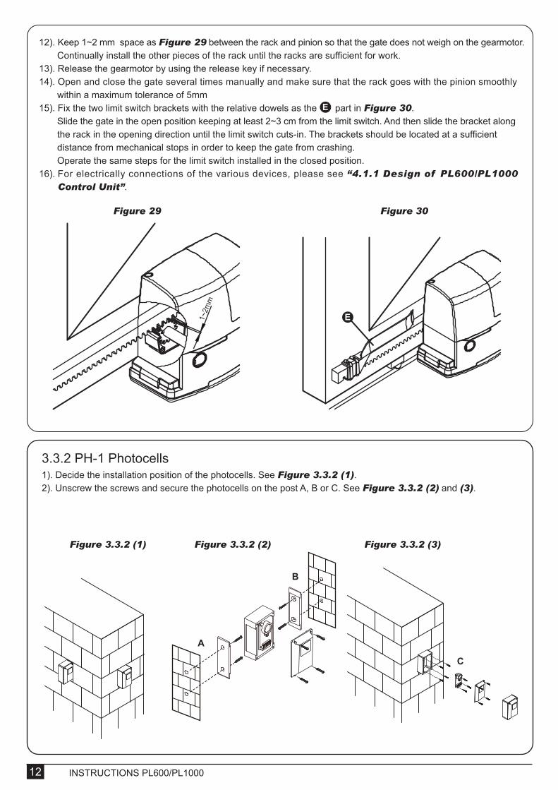
3.3.2 PH-1 Photocells1). Decide the installation position of the photocells. See Figure 3.3.2 (1).2). Unscrew the screws and secure the photocells on the post A, B or C. See Figure 3.3.2 (2) and (3).
E
12). Keep 1~2 mm space as Figure 29 between the rack and pinion so that the gate does not weigh on the gearmotor. Continually install the other pieces of the rack until the racks are sufficient for work. 13). Release the gearmotor by using the release key if necessary.14). Open and close the gate several times manually and make sure that the rack goes with the pinion smoothly within a maximum tolerance of 5mm15). Fix the two limit switch brackets with the relative dowels as the part in Figure 30. Slide the gate in the open position keeping at least 2~3 cm from the limit switch. And then slide the bracket along the rack in the opening direction until the limit switch cuts-in. The brackets should be located at a sufficient distance from mechanical stops in order to keep the gate from crashing. Operate the same steps for the limit switch installed in the closed position.16). For electrically connections of the various devices, please see “4.1.1 Design of PL600/PL1000 Control Unit”.
Figure 29 Figure 301~
2mm
E
Figure 3.3.2 (1) Figure 3.3.2 (2) Figure 3.3.2 (3)
A
B
C

INSTRUCTIONS PL600/PL1000 13
3.3.3 PF-1 Flashing Light1). Decide the installation position of the flashing light. The flashing light has to be installed near the gate and easy to be seen by users and passersby. The flashing light can be installed horizontally or vertically. See Figure 3.3.3 (1).2). Unscrew the four screws on the light base and separate the base with the bottom as shown in Figure 3.3.3 (2).3.) Connect the wires and penetrate the wires into the hole of the base. See Figure 3.3.3 (3).4.) Drill the holes in the wall and fix the bottom to the wall by three screws. See Figure 3.3.3 (4).
3). Wiring connection: TX: Connect the (1) and (2) terminals on the transmitter with the terminals +12V and GND on the PL600/ 1000 PCB. RX: Connect the (1), (2) and (4) NC terminals on the receiver with the terminals+12V、GND and PH1 on the PCB600/1000 PCB. And use an extra wire to connect terminal (2) and (5) on the receiver as bridge. See Figure 3.3.2 (4) Figure 3.3.2 (5).
Figure 3.3.2 (4)
Figure 3.3.3 (1) Figure 3.3.3 (2) Figure 3.3.3 (3) Figure 3.3.3 (4)
Figure 3.3.2 (5)
CACC
NA: Normal OpenNC: Normal Close : DC(+) Input Voltage : DC(-) Input Voltage
C: CommonCA: AC(12~24)CC: DC(12~24)VERT:VerticalORIZ:Horizontal
ORIZ
NA NC C
1 2 3 4 5
Power LED: Green
Transmitter
Vertical AdjustmentHorizontal Adjustment
LED:Red(Beam Alignment)
CACC
NA NC C1 2 3 4 5
ORIZ
VERT
Receiver
CACC
NA NC C1 2 3 4 5
ORIZ
VERT

INSTRUCTIONS PL600/PL100014
3.3.4 PKS-1 Key Selector1). PKS-1 key selector is installed outside and close to the gate at the height of about 100cm, so that it could be used by most people. Decide the installation position of PKS-1 first. See Figure 3.3.4 (1).2). Remove the round cover (A) by prizing it out with a screwdriver. See Figure 3.3.4 (2).3). Unscrew the two screws beside the lock body. See Figure 3.3.4 (3).4). Turn the key and separate the bottom of the shell with the lock body. See Figure 3.3.4 (4).
5). Connect the four wires of the light and the antenna to the PCB terminals and place the wires into the conduit if necessary. See Figure 3.3.3 (5).6). Tighten the four screws back on the light base. Figure 3.3.3 (6)7). Replacing the bulb set. See Figure 3.3.3 (7) 7.1) Unscrew the flashing light wires from the PCB terminals and make sure the power of the light is off. 7.2) Release the three screws (A)、(B)、(C) of the flashing light cover. 7.3) Separate the flashing light cover and replace the bulb set with a new one. 7.4) Tighten the three screws (A)、(B)、(C) of the flashing light cover.
Figure 3.3.3 (5) Figure 3.3.3 (6) Figure 3.3.3 (7)
Figure 3.3.4 (1) Figure 3.3.4 (2)
Figure 3.3.4 (3) Figure 3.3.4 (4)
A
BC
1000
mm
A

INSTRUCTIONS PL600/PL1000 15
3.3.5 PPB-1 Push Button1). PPB-1 push button is installed indoors at the height of about 100cm, so that it could be used by most people. 2). Remove the round cover (A) by prizing it out with a screwdriver. See Figure 3.3.5 (1). 3). Unscrew the two screws beside the button.4). Separate the upper shell with the bottom. See Figure 3.3.5 (2). 5). Breach the three holes at the bottom and mark the points by the holes as reference.6). Drill the holes in the wall and fix the bottom to the wall by three screws. See Figure 3.3.5 (3).
5). Breach the three holes at the bottom and mark the points by the holes as reference.6). Drill the holes in the wall and fix the bottom to the wall by three screws. See Figure 3.3.4 (5).7). Connect the electric wires to the terminals as shown in Figure 3.3.4(6), and it’s not required to distinguish any polarity. The terminals can be removed for connecting the wires easily.8). Turn the key and insert the shell on the bottom. Turn the key back to the center position and the shell will be fixed to the bottom.9). Tighten the lock body with the two screws and insert the round cover by pressing it to attach to the whole unit.
3.4 Power Supply ConnectionsPlease kindly notice that the operation of power connection should be carried out by a qualified electrician with following steps:
1). Make sure the gearmotor is not connected to the power supply before the installation is done.2). Make sure all the wires are firmly connected.3). Supply the gearmotor with the power.
Figure 3.3.4 (5)
Figure 3.3.5 (1) Figure 3.3.5 (2)
Figure 3.3.5 (3)
Figure 3.3.4 (6)
A

INSTRUCTIONS PL600/PL100016
4) Final Checks and Start Up
4.1 Initial Checks4.1.1 Design of PL600/PL1000 control unit
If the Led display is in normal performing refer to “4.2.1”, you can control the gate by either transmitters or the button on the board: “UP”-clockwise moving, “SET”- stop and “DOWN”- Counterclockwise moving.
Notice 1: Reset function- In any condition of gate moving and stop, press SW3 and SW5 (clockwise moving and counterclockwise moving) for 3 secs, then the LED will display “CLR” meaning “reset successfully”. All functions including system learning will return to the factory setting and the status before system learning.
LED1 PhotocellsLED2 PhotocellsLED3 RF Learning
ANTGND
RF Learn (SW1)
LED Display
UP (SW3)
SET (SW4)
DOWN (SW5)
SW2
ON OFF
Jumper4
3
1 2 3 4 5 6 7 8 9
6
6 73 4
9 6 8 9
9 6 9
10
10
11
11 12 13 14
2 1
RF LEARN
UP
SET
DOWN
ON/OFF

INSTRUCTIONS PL600/PL1000 17
2 channel transmitter
4 channel transmitter
(A)Button: “Open- Stop- Close- Stop”(B)Button: Long Press for other device turn-on, like garage door system
(A) Button: “Open- Stop- Close- Stop”(B) Button: Long Press for other device turn-on, like garage door system(C) Button: “Pedestrian mode”Or(D) Button: “Pedestrian mode”
(A)Button: “Open- Stop- Close- Stop”(B)Button: “Pedestrian mode”
(A) Button: “Open- Stop- Close- Stop”(B) Button: “Pedestrian mode”(C) Button: Long Press for other device turn-on, like garage door systemOr(D) Button: Long Press for other device turn-on, like garage door system
Channel/Functions SW2 switch on SW2 switch off
1). The transmitter Reaction
LED1 Photocells
LED2 Photocells
LED3 RF Learning
LED1 will be on when the first pair of the photocells are activated.
LED2 will be on when the second pair of the photocells are activated.
LED3 will be on when RF-learn button is pressed.
LED Indication Descriptions
F1
F2
Options of Gate Opening directionAutomatic Closing
F1-0F1-1F2-0F2-1F2-2F2-3F2-4F2-5F2-6F2-7F2-8
Clockwise OpeningCounterclockwise OpeningNo automatic closing 5 seconds15 seconds30 seconds45 seconds60 seconds80 seconds120 seconds180 seconds
1. The function can adjust the direction of gate opening. 2. The factory setting is "F1-1".1. This function can cause the gate to close automatically after the paused time. 2. The factory setting is "F2-2”: 15secs as the pause time.
LED Display Definition Function Value Description
4.1.2 Recognition of LED
4.1.3 Checking the Gate Movements1). Release the gearmotor with the release key and move the gate to the middle so that it is free to move in both opening and closing directions; then lock the gearmotor.2). Perform the gate opening and closing several times and make sure the gates reaches the limit switch at least 2~3 centimeters before the mechanical stop.
4.2 Programmable Functions Lists
Important notice: (1) Jumper 4: ② and ③ in place: remote control button (C) usable ; Jumper 4: ① and ② in place: remote control button (D) usable.(2) Pedestrian mode follows function “F6-0~F6-5” settings.
3 2 1 3 2 1
Button (C) Usable Button (D) Usable
2). Transmitter Memorizing and Erasing Process(1) Transmitter Memoring: Press “RF LEARN” button for 2 seconds, and the LED3 is on; then press the transmitter (A) button; the LED3 will blink twice and then be off. The system learning is complete.(2) Transmitter Memory Erasing: Press “RF LEARN” button for 5~6 seconds as LED 3 is on, then wait for LED3 off.
INSTRUCTIONS PL600/PL100018
F3
F4
F5
F6
F7
F8
F9
F4-1F4-2F4-3F4-4
F5-1
F5-2
F5-3
F5-4
F5-5
F5-6
F5-7
F5-8
F5-9
F6-0F6-1F6-2F6-3F6-4F6-5F7-0
F7-1
F8-0F8-1F8-2F8-3F8-4F9-1F9-2
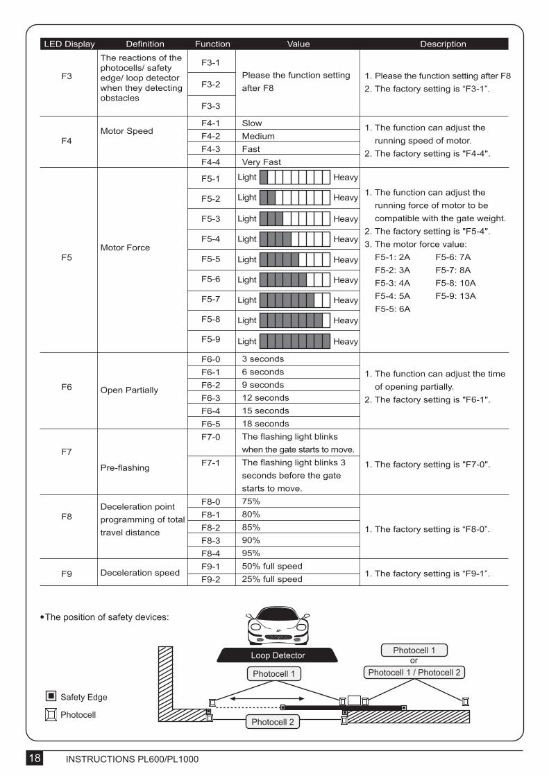
LED Display Definition Function Value DescriptionThe reactions of the photocells/ safety edge/ loop detector when they detecting obstacles
Motor Speed
Motor Force
Open Partially
Pre-flashing
Deceleration point programming of total travel distance
Deceleration speed
SlowMediumFastVery Fast
3 seconds6 seconds9 seconds12 seconds15 seconds18 secondsThe flashing light blinks when the gate starts to move.The flashing light blinks 3 seconds before the gate starts to move.75%80%85%90%95%50% full speed 25% full speed
Please the function setting after F8
F3-1
F3-2
F3-3
Light Heavy
Light Heavy
Light Heavy
Light Heavy
Light Heavy
Light Heavy
Light Heavy
Light Heavy
Light Heavy
1. Please the function setting after F82. The factory setting is “F3-1”.
1. The function can adjust the running speed of motor. 2. The factory setting is "F4-4".
1. The function can adjust the running force of motor to be compatible with the gate weight. 2. The factory setting is "F5-4". 3. The motor force value: F5-1: 2A F5-6: 7A F5-2: 3A F5-7: 8A F5-3: 4A F5-8: 10A F5-4: 5A F5-9: 13A F5-5: 6A
1. The function can adjust the time of opening partially. 2. The factory setting is "F6-1".
1. The factory setting is "F7-0".
1. The factory setting is “F8-0”.
1. The factory setting is “F9-1”.
● The position of safety devices:
Photocell 1 / Photocell 2
Photocell
Safety Edge
Photocell 1or
Photocell 1
Loop Detector
Photocell 2

INSTRUCTIONS PL600/PL1000 19
4.2.1 Programmable Functions of LED Display
Gate StatusClosedOpen Stop during movingClosingOpening
Photocell 2Stop opening
No effectStop opening
No effectCloses the leaf
Photocell 1No effect
OpenNo effect
Reloads automatic closing timeReloads automatic closing time
Photocell 1/ Photocell 2Stop opening
Locks and, on release, reverses to openLocks and, on release, continues opening
Logic F3-1 The reactions of the photocells when detecting obstacles
Gate StatusClosedOpen Stop during movingClosingOpening
Safety EdgeStop opening
Stop opening/ closingReverses to open for 2 secondsReverses to close for 2 seconds
Photocell 1No effect
Reloads automatic closing timeOpen
No effect
Reloads automatic closing time
Logic F3-2 The reactions of the safety edge/ photocell when detecting obstacles
Gate StatusClosedOpen Stop during movingClosingOpening
Loop DetectorOpen
OpenOpenOpen
Photocell 1No effect
Reloads automatic closing timeOpen
No effect
Reloads automatic closing time
Logic F3-3 The reactions of the loop detector/ photocell when detecting obstacles
LED Display Programmable Functions
“N-L”: The PL600 system learning is not done.
“RUN”: The PL600 system is in normal performing.
“LEA”: Enter learning mode and then wait for learning instructions. The operation of gate learning:(1). Press “SET” one time; then press “SET” + “DOWN” for 3seconds, and the LED display shows “LEA” ; and then press the transmitter (A) button one time. After 1~3seconds, the LED display shows “ARN”
“ARN”: The system learning is in progress.The Auto-learning process of gate moving: “Gate open to the end- stop close to the end- stop.
● F3 function settings:

INSTRUCTIONS PL600/PL100020
For exmple: How to set the function “F1-0”; the steps are following:
(1) Press the “SET” button for 3seconds then releases it, and the system enters the first option. The LED will display “F1” (*) as the right hand-side picture.
(*) If you would like to enter “F2” function or others as the first option, please press the “UP” button to adjust F2~F8 until you get “F2”.
1.
4.2.2 Operations for Function Settings
5) Testing
Step Operations LED Display after the Step
(2) After completing the operation (1), then press the “SET” button again, you will enter the second option as the right hand-side picture. And you will see the third number for the second option.
(3) Continually press the “Down” button until you search the function “0” (**) of F1 as the right hand-side picture. “F1-0” is set completely.
(**) If you would like to set one of functions “0 ~ 8” as the second option, please press the “UP” or “Down” button to adjust it.
(4) If you would continue setting up the next functions, please press “SET” to return the first option, like F1 or F2 or F3…or F8.
For example, after complete “F1-0” setting. You would continue setting “F2-5”, please press “SET” to return the formal option. The LED display shows the first two numbers as as the first option as the right hand-side picture, “F1”. And then follow the operation (*) and (2) ~ (3) until you get “F2-5” as the right hand-side picture. “F2-5” is set completely.
After setting all functions you need, then wait for 10seconds, the LED will display “RUN”. And you can use transmitter to operate the gate.
2.
3.
Make sure the notices included in chapter 1 “WARNINGS” have been carefully observed.● Release the gearmotor with the proper release key.● Make sure the gate can be moved manually during opening and closing phases with a force of max. 390N (40 kg approx.)● Lock the gearmotor. ● Using the Key selector switch, push button device or the radio transmitter, test the opening, closing and stopping of the gate and make sure that the gate is in the intended direction.● Check the devices one by one (photocells, flashing light, key selector, etc.) and confirm the control unit recognizes each device.● Measure the impact force according to EN 12445 standard. If “motor force” control is used to support the system for the reduction of the impact force, try to find the adjustment which offers the best results.

INSTRUCTIONS PL600/PL1000 21
6) Maintenance and Disposal
The maintenance operations must be performed in strict compliance with the safety directions provided in the manual and according to the applicable legislation and standard.In order to have good and safety performances, test the gate-automated system weekly and have qualified installation personnel to check and maintain the system at least every 6-month.
6.1 Maintenance
Some electronic components and the batteries may contain polluting materials; do not pollute the environment. Make sure the recycling or disposal systems available under the regulations locally in fore.PL600/PL1000 are consist of different types of materials; some of them can be recycled such as aluminum, plastic, electric cables while some need to be disposed, such as electronic boards.
6.2 Disposal
7) Additional Information
After you have added or removed any devices, the automation system must be tested again according to the operation mentioned in paragraph 5 “Testing”.
7.1 Adding or Removing Device
8) Technical Characteristics
8.1 PL600/ PL1000
Motor Gear type Peak thrust Nominal thrust Power supply Nominal input power Maximum operating current Maximum gate weight Maximum gate length Duty cycle Operating Temperature Dimension Weight Main power supply Back-up battery Transformer Receiver board
24Vdc motor with mechanical release Worm gear 6500N 6000N 24Vdc 2.5A 5.5A for maximum 10 seconds. 600 kg per leaf 8 meters 20% -20℃~+50℃ 333mm*216mm*287mm10.2 kg 230Vac/50Hz, 110Vac/50Hz 2pcs of batteries for emergency operation, 1.2A each, 1.1kg6A, 24V 433.92MHz; 200 transmitters memory
24Vdc motor with mechanical release Worm gear 10500N 10000N 24Vdc 2.5A 5.5A for maximum 10 seconds. 1000 kg per leaf 12 meters 20% -20℃~+50℃ 333mm*216mm*287mm10.4 kg 230Vac/50 Hz , 110Vac/50Hz2pcs of batteries for emergency operation, 1.2A each, 1.1kg11.4A, 22V 433.92MHz; 200 transmitters memory
PL600 PL1000
8.2 PH-1 Photocells
Detection typeOperating distanceResponse timeInput voltageOperating TemperatureProtection classDimension
Through beam30 meters100msAC/DC 12~24V-20℃~+60℃IP6659mm * 87mm * 38mm

INSTRUCTIONS PL600/PL100022
8.3 PR-1 Radio Transmitter
ApplicationFrequencyCodingButtonsPower SupplyOperating TemperatureDimension
Radio transmitter for remote control of PL600/PL1000433.92MhzRolling code2, for single-gate or dual-gate operation3V with one CR2032 button type lithium battery-20℃~+50℃71.5mm * 33mm * 14mm
8.4 PF-1 Flashing Light
ApplicationLampOperating TemperatureInstallationDimension
For warning purpose during leaves movement24Vdc Halogens bulb-20℃~+50℃horizontally or vertically installed205mm * 80mm * 75mm
8.5 PKS-1 Key Selector
ApplicationInstallationOperating TemperatureDimension
For outdoor useWall mounted vertically-20℃~+50℃85mm*60.5mm*40.5mm
8.6 PPB-1 Push Button
ApplicationInstallationOperating TemperatureDimension
For outdoor useWall mounted vertically-20℃~+50℃85mm*60.5mm*40.0mm

INSTRUCTIONS PL600/PL1000 23
Applicant: Powertech Electronics Inc.Manufacturer: Timotion Technology Co., Ltd.Address: Shiyong Minying Industrial Zone, Hengli Town, DongGuan City, GuangDong, China
Model: PL600; PL1000; PR-1
1. Certificate of conformity of a product with the essential requirements art. 3.2 of the R&TTE Directive 1999/5/EC.2. The above product has been tested with the listed standards and in compliance with the European Directive LVD 2006/95/EC.3. The submitted sample of the above product has been tasted for CE marking according to the following European Directives: 2006/42/EC Machinery Directive.
Comply with the following Standards:
EN 301489-1 V1.8.1: 2008EN 301489-3 V1.4.1: 2002EN 300220-1 V2.1.1: 2006EN 300220-2 V2.1.2: 2007
EN 60335-1: 2002+A11:2004+A1:2004+A12:2006+A2:2006+A13:2008EN 60335-2-103: 2003EN 62233: 2008
EN 12445: 2001EN 12453: 2001
And also declare that the machinery may not be put into service until the machine, which will be integrated or become one of the components, and announced to comply with the provisions as the required.
David Lan
(Deputy Managing Director)
Taiwan, November 20, 2011
Declaration of Conformity


Worm gear provides durability and silence in motor operation.Slowdown during the ends of opening and closing phases.
DESIGNED FOR RESIDENTIAL APPLICATION
KIT PL600/PL1000SLIDING GATE OPENERS
THE STRONGEST SOLUTION FOR SLIDING GATES
PL600 Gear MotorPL600 maximum gate weight : 600kg.24V DC electro-mechanical gear motors for residential use.Worm gear provides durability and silence in motor operation.Slowdown during the ends of opening and closing phases.Magnetic limit switch and spring limit switch are available forcustomer’s choice.
PL1000 Gear MotorPL1000 maximum gate weight : 1000kg.24V DC electro-mechanical gear motors for residential use.Worm gear provides durability and silence in motor operation.Slowdown during the ends of opening and closing phases.Magnetic limit switch and spring limit switch are available for customer’s choice.
LCD display panel provides easy programming.2 back-up batteries for power failure operation.Incorporated radio receiver matched with 200 transmitters.Safe design to prevent PCB burned for wrong wiring connection.7 settings of motor torque adjustment.
PC600/1000
Over- current function meets European safety requirements.Modern appearance and easy installation.9 modes of gate auto-closed setting.3 Digit LED Display provides user-friendly system programming.
Flashing LightConvenient horizontal and vertical installations.Stylish shape and fashionable appearance.24V halogen bulb offers excellent illumination and long lifetime.
Eye-catching appearance for outdoor installation.Two keys attached with the key selector to open the gate without the transmitter.
IP66 water proof for outdoor environment use.Long sensing distance for 30 meters.AC/DC 12~24V application.
Rolling code 433MHZ transmitter.30 meters transmitting distance.Two buttons for single-gate or dual-gate operation.
Easy opening for inddor use.Novel design of the appearance for opening the gate without the transmitter.
Rack of 1m long and 1cm thick.PH-1
PKS-1
PF-1
PRK-1
PPB-1
PR-1
Photocells
Key Selector
Control Board
Powertech Electronics Inc.TEL: +886-2-8667-5222 Address: 14F., No.105, Minquan Rd., Xindian Dist., New Taipei City, 23141, Taiwan (R.O.C.)E-mail: [email protected]
FAX: +886-2-8667-5223
http://www.gateopener.tw