design study of superconducting sextupole magnet using hts coated conductor for neutron-focusing...
TRANSCRIPT
www.elsevier.com/locate/physc
Physica C 445–448 (2006) 1095–1098
Design study of superconducting sextupole magnet using HTScoated conductor for neutron-focusing device
T. Tosaka a,*, K. Koyanagi a, M. Ono a, T. Kuriyama a, I. Watanabe a, K. Tsuchiya b,J. Suzuki c, T. Adachi d, H.M. Shimizu d
a TOSHIBA Corporation, 2-4 Suehiro, Tsurumi, Yokohama 230-0045, Japanb KEK, Tsukuba, Ibaraki 305-0801, Japanc JAEA, Tokai, Ibaraki 319-1195, Japan
d RIKEN, Wako, Saitama 351-0198, Japan
Available online 4 August 2006
Abstract
We performed a design study of sextupole magnet using high temperature superconducting (HTS) wires. The sextupole magnet is usedas a focusing lens for neutron-focusing devices. A neutron-focusing device is desired to have a large aperture and a high magnetic fieldgradient of G, where G = 2B/r2, B is the magnetic field and r is a distance from the sextupole magnet axis. Superconducting magnets offerpromising prospects to meet the demands of a neutron-focusing device. Recently NbTi coils of low temperature superconducting(LTS) have been developed for a sextupole magnet with a 46.8 mm aperture. The maximum magnetic field gradient G of this magnetis 9480 T/m2 at 4.2 K and 12,800 T/m2at 1.8 K.
On the other hand, rapid progress on second generation HTS wire has been made in increasing the performance of critical current andin demonstrating a long length. The second generation HTS wire is referred to as coated conductor. It consists of tape-shaped base uponwhich a thin coating of superconductor, usually YBCO, is deposited or grown. This paper describes a design study of sextupole magnetusing coated conductors.� 2006 Published by Elsevier B.V.
PACS: 03.75.Be
Keywords: Sextupole magnet; Neutron lens; Coated conductor; YBCO
1. Introduction
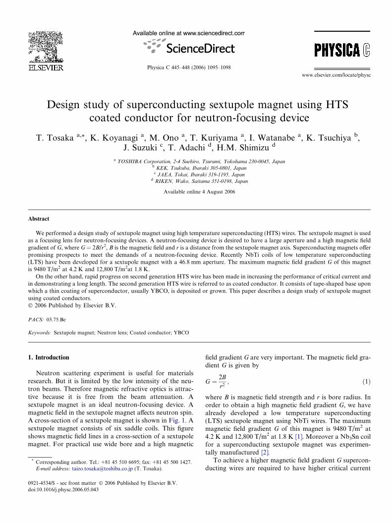
Neutron scattering experiment is useful for materialsresearch. But it is limited by the low intensity of the neu-tron beams. Therefore magnetic refractive optics is attrac-tive because it is free from the beam attenuation. Asextupole magnet is an ideal neutron-focusing device. Amagnetic field in the sextupole magnet affects neutron spin.A cross-section of a sextupole magnet is shown in Fig. 1. Asextupole magnet consists of six saddle coils. This figureshows magnetic field lines in a cross-section of a sextupolemagnet. For practical use wide bore and a high magnetic
0921-4534/$ - see front matter � 2006 Published by Elsevier B.V.
doi:10.1016/j.physc.2006.05.043
* Corresponding author. Tel.: +81 45 510 6695; fax: +81 45 500 1427.E-mail address: [email protected] (T. Tosaka).
field gradient G are very important. The magnetic field gra-dient G is given by
G ¼ 2Br2; ð1Þ
where B is magnetic field strength and r is bore radius. Inorder to obtain a high magnetic field gradient G, we havealready developed a low temperature superconducting(LTS) sextupole magnet using NbTi wires. The maximummagnetic field gradient G of this magnet is 9480 T/m2 at4.2 K and 12,800 T/m2 at 1.8 K [1]. Moreover a Nb3Sn coilfor a superconducting sextupole magnet was experimen-tally manufactured [2].
To achieve a higher magnetic field gradient G supercon-ducting wires are required to have higher critical current
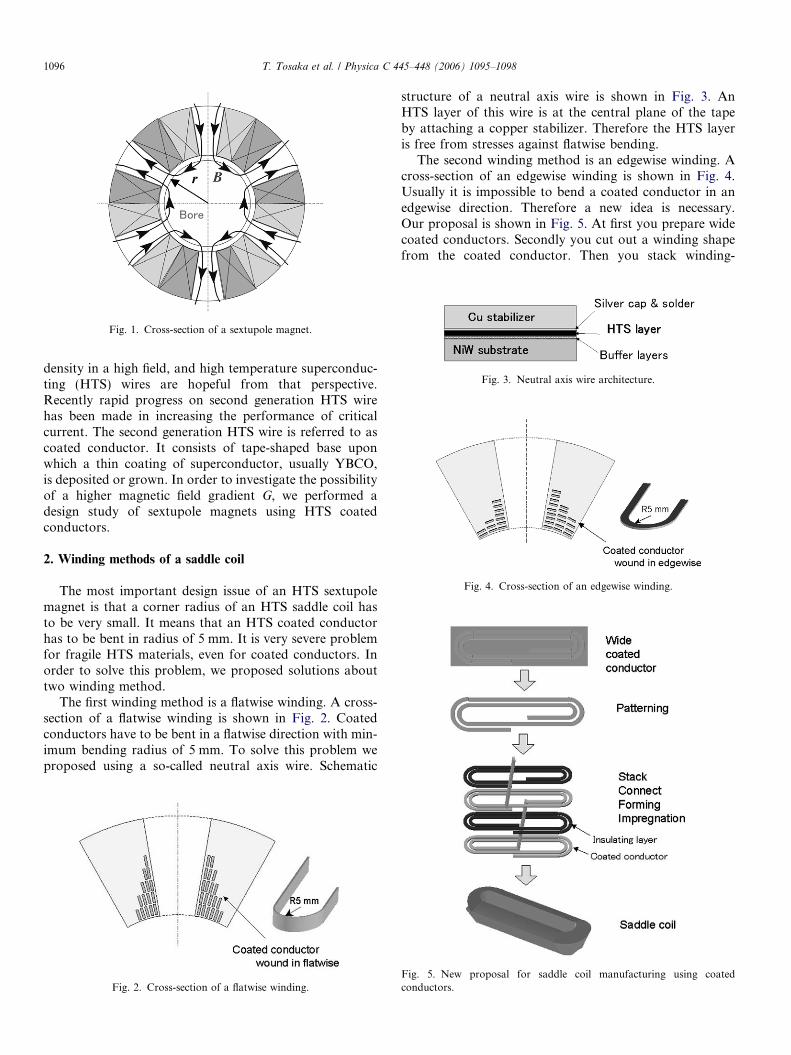
Fig. 3. Neutral axis wire architecture.
Fig. 4. Cross-section of an edgewise winding.
Fig. 1. Cross-section of a sextupole magnet.
1096 T. Tosaka et al. / Physica C 445–448 (2006) 1095–1098
density in a high field, and high temperature superconduc-ting (HTS) wires are hopeful from that perspective.Recently rapid progress on second generation HTS wirehas been made in increasing the performance of criticalcurrent. The second generation HTS wire is referred to ascoated conductor. It consists of tape-shaped base uponwhich a thin coating of superconductor, usually YBCO,is deposited or grown. In order to investigate the possibilityof a higher magnetic field gradient G, we performed adesign study of sextupole magnets using HTS coatedconductors.
2. Winding methods of a saddle coil
The most important design issue of an HTS sextupolemagnet is that a corner radius of an HTS saddle coil hasto be very small. It means that an HTS coated conductorhas to be bent in radius of 5 mm. It is very severe problemfor fragile HTS materials, even for coated conductors. Inorder to solve this problem, we proposed solutions abouttwo winding method.
The first winding method is a flatwise winding. A cross-section of a flatwise winding is shown in Fig. 2. Coatedconductors have to be bent in a flatwise direction with min-imum bending radius of 5 mm. To solve this problem weproposed using a so-called neutral axis wire. Schematic
Fig. 2. Cross-section of a flatwise winding.
structure of a neutral axis wire is shown in Fig. 3. AnHTS layer of this wire is at the central plane of the tapeby attaching a copper stabilizer. Therefore the HTS layeris free from stresses against flatwise bending.
The second winding method is an edgewise winding. Across-section of an edgewise winding is shown in Fig. 4.Usually it is impossible to bend a coated conductor in anedgewise direction. Therefore a new idea is necessary.Our proposal is shown in Fig. 5. At first you prepare widecoated conductors. Secondly you cut out a winding shapefrom the coated conductor. Then you stack winding-
Fig. 5. New proposal for saddle coil manufacturing using coatedconductors.
T. Tosaka et al. / Physica C 445–448 (2006) 1095–1098 1097
shaped coated conductors with insulating layers and con-nect the coated conductors each other. After forming andimpregnation processes, finally you can obtain a HTS sad-dle shape coil. This winding method has two advantages.The first is easy to manufacture a saddle shape coil havingsmall corner radius. The second is unnecessary to use neu-tral axis wires. A neutral axis wire is improved on mechan-ical properties but critical current density is reduced byhalf.
3. Performance of a coated conductor
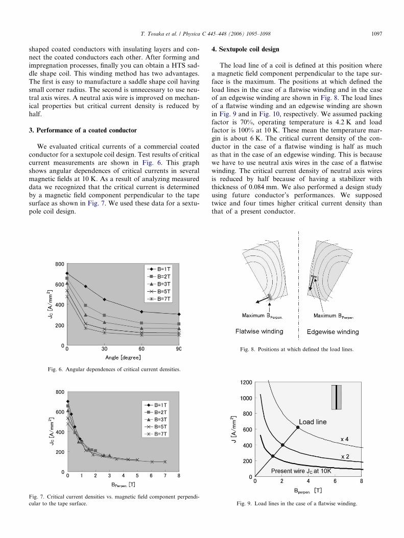
We evaluated critical currents of a commercial coatedconductor for a sextupole coil design. Test results of criticalcurrent measurements are shown in Fig. 6. This graphshows angular dependences of critical currents in severalmagnetic fields at 10 K. As a result of analyzing measureddata we recognized that the critical current is determinedby a magnetic field component perpendicular to the tapesurface as shown in Fig. 7. We used these data for a sextu-pole coil design.
Fig. 6. Angular dependences of critical current densities.
Fig. 7. Critical current densities vs. magnetic field component perpendi-cular to the tape surface.
4. Sextupole coil design
The load line of a coil is defined at this position wherea magnetic field component perpendicular to the tape sur-face is the maximum. The positions at which defined theload lines in the case of a flatwise winding and in the caseof an edgewise winding are shown in Fig. 8. The load linesof a flatwise winding and an edgewise winding are shownin Fig. 9 and in Fig. 10, respectively. We assumed packingfactor is 70%, operating temperature is 4.2 K and loadfactor is 100% at 10 K. These mean the temperature mar-gin is about 6 K. The critical current density of the con-ductor in the case of a flatwise winding is half as muchas that in the case of an edgewise winding. This is becausewe have to use neutral axis wires in the case of a flatwisewinding. The critical current density of neutral axis wiresis reduced by half because of having a stabilizer withthickness of 0.084 mm. We also performed a design studyusing future conductor’s performances. We supposedtwice and four times higher critical current density thanthat of a present conductor.
Fig. 8. Positions at which defined the load lines.
Fig. 9. Load lines in the case of a flatwise winding.
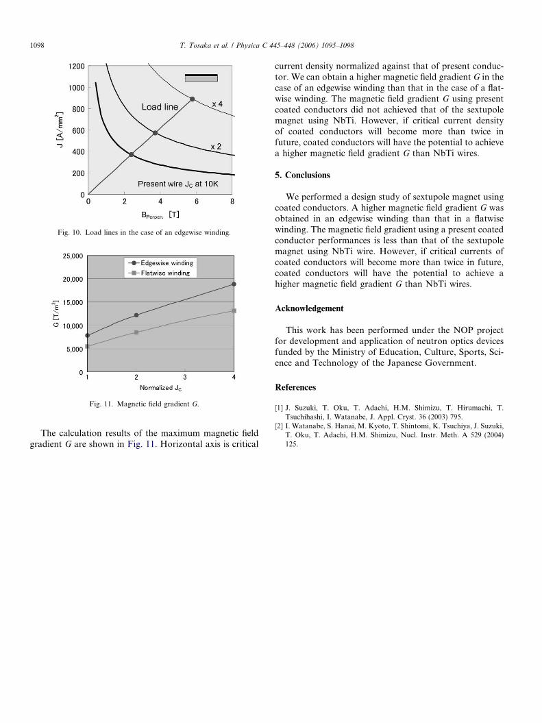
Fig. 11. Magnetic field gradient G.
Fig. 10. Load lines in the case of an edgewise winding.
1098 T. Tosaka et al. / Physica C 445–448 (2006) 1095–1098
The calculation results of the maximum magnetic fieldgradient G are shown in Fig. 11. Horizontal axis is critical
current density normalized against that of present conduc-tor. We can obtain a higher magnetic field gradient G in thecase of an edgewise winding than that in the case of a flat-wise winding. The magnetic field gradient G using presentcoated conductors did not achieved that of the sextupolemagnet using NbTi. However, if critical current densityof coated conductors will become more than twice infuture, coated conductors will have the potential to achievea higher magnetic field gradient G than NbTi wires.
5. Conclusions
We performed a design study of sextupole magnet usingcoated conductors. A higher magnetic field gradient G wasobtained in an edgewise winding than that in a flatwisewinding. The magnetic field gradient using a present coatedconductor performances is less than that of the sextupolemagnet using NbTi wire. However, if critical currents ofcoated conductors will become more than twice in future,coated conductors will have the potential to achieve ahigher magnetic field gradient G than NbTi wires.
Acknowledgement
This work has been performed under the NOP projectfor development and application of neutron optics devicesfunded by the Ministry of Education, Culture, Sports, Sci-ence and Technology of the Japanese Government.
References
[1] J. Suzuki, T. Oku, T. Adachi, H.M. Shimizu, T. Hirumachi, T.Tsuchihashi, I. Watanabe, J. Appl. Cryst. 36 (2003) 795.
[2] I. Watanabe, S. Hanai, M. Kyoto, T. Shintomi, K. Tsuchiya, J. Suzuki,T. Oku, T. Adachi, H.M. Shimizu, Nucl. Instr. Meth. A 529 (2004)125.