design standards no. 3 water conveyance facilities, fish ... · pdf filewater conveyance...
TRANSCRIPT
U.S. Department of the Interior Bureau of Reclamation April 2014
Design Standards No. 3
Water Conveyance Facilities, Fish Facilities, and Roads and Bridges
Chapter 4: Tunnels, Shafts, and Caverns Phase 4 (Final)
Mission Statements
The U.S. Department of the Interior protects America’s natural
resources and heritage, honors our cultures and tribal communities,
and supplies the energy to power our future.
The mission of the Bureau of Reclamation is to manage, develop,
and protect water and related resources in an environmentally and
economically sound manner in the interest of the American public.
Design Standards Signature Sheet
Design Standards No. 3
Water Conveyance Facilities, Fish Facilities, and Roads and Bridges DS-3(4)-3: Phase 4 (Final) April 2014
Chapter 4: Tunnels, Shafts, and Caverns

Foreword
Purpose
The Bureau of Reclamation (Reclamation) design standards present technical requirements and
processes to enable design professionals to prepare design documents and reports necessary to
manage, develop, and protect water and related resources in an environmentally and
economically sound manner in the interest of the American public. Compliance with these
design standards assists in the development and improvement of Reclamation facilities in a way
that protects the public's health, safety, and welfare; recognizes needs of all stakeholders; and
achieves lasting value and functionality necessary for Reclamation facilities. Responsible
designers accomplish this goal through compliance with these design standards and all other
applicable technical codes, as well as incorporation of the stakeholders’ vision and values, that
are then reflected in the constructed facilities.
Application of Design Standards Reclamation design activities, whether performed by Reclamation or by a non-Reclamation
entity, must be performed in accordance with established Reclamation design criteria and
standards, and approved national design standards, if applicable. Exceptions to this requirement
shall be in accordance with provisions of Reclamation Manual Policy, Performing Design and
Construction Activities, FAC P03.
In addition to these design standards, designers shall integrate sound engineering judgment,
applicable national codes and design standards, site-specific technical considerations, and
project-specific considerations to ensure suitable designs are produced that protect the public's
investment and safety. Designers shall use the most current edition of national codes and design
standards consistent with Reclamation design standards. Reclamation design standards may
include exceptions to requirements of national codes and design standards.
Proposed Revisions
Reclamation designers should inform the Technical Service Center (TSC), via Reclamation’s
Design Standards Website notification procedure, of any recommended updates or changes to
Reclamation design standards to meet current and/or improved design practices.

Chapter Signature Sheet Bureau of Reclamation Technical Service Center
Design Standards No. 3
Water Conveyance Facilities, Fish Facilities, and Roads and Bridges Chapter 4: Tunnels, Shafts, and Caverns
DS-3(4)-3:1 Phase 4 (Final)
April 2014
Chapter 4 – Tunnels, Shafts, and Caverns is an existing chapter within Design
Standards No. 3 and was revised to include the addition of:
Added requirement for Geotechnical Baseline Report
Added range of design rugosities for lined and unlined tunnels
Added typical velocities based on tunnel function and lined and unlined
tunnels
Updated safety requirement on use of timber
Added design guidance on tunnels in squeezing ground
Expanded horizontal curve requirements
Redefined terms “deviation” and “tolerances” to match current definitions
Updated design code references
1 DS-3(4)-3 refers to Design Standards No. 3, chapter 4, revision 3.
Expanded seismic requirements for tunnel design
Added list of typical construction methods and initial support for shafts
Decreased acceptable station marker spacing
Expanded and updated estimated average daily advance rates of hard rock
tunneling, shaft sinking and raise bore.
Expanded and updated excavation methods capabilities
Added description and figure of American lake tap method
Added criteria for filling and draining tunnels.

DS-3(4)-3 April 2014 4-i
Contents
Page
Chapter 4: Tunnels, Shafts, and Caverns
4.1 Introduction .............................................................................................. 4-1 4.1.1 Purpose ..................................................................................... 4-1 4.1.2 Scope ........................................................................................ 4-1 4.1.3 Deviations from Standards ....................................................... 4-1 4.1.4 Revisions of Standards ............................................................. 4-1
4.1.5 Applicability ............................................................................ 4-2 4.1.6 General ..................................................................................... 4-2
4.2 Design Data and Interpretation ................................................................ 4-2
4.2.1 Data Collection ........................................................................ 4-2 4.2.2 Geotechnical Baseline Report .................................................. 4-3
4.3 Functional Design .................................................................................... 4-3 4.3.1 Portals and Intakes ................................................................... 4-3
4.3.2 Transitions................................................................................ 4-4 4.3.3 Tunnel Hydraulics .................................................................... 4-4
4.3.4 Control Structures .................................................................... 4-8 4.3.5 Water Measurements ............................................................... 4-8 4.3.6 Ventilation................................................................................ 4-9
4.3.7 Lighting .................................................................................... 4-9 4.3.8 Safety ..................................................................................... 4-10
4.3.8.1 General ................................................................. 4-10
4.3.8.2 Timber .................................................................. 4-10
4.4 General Design Considerations.............................................................. 4-10 4.4.1 Geometric Design .................................................................. 4-10
4.4.1.1 Shape .................................................................... 4-10 4.4.1.2 Size ....................................................................... 4-14 4.4.1.3 Gradient................................................................ 4-16
4.4.1.4 Horizontal Curves ................................................ 4-17 4.4.1.5 Typical Sections ................................................... 4-17 4.4.1.6 Deviations and Tolerances ................................... 4-17
4.4.2 Ground Cover Requirements ................................................. 4-18 4.4.3 Ground Settlement ................................................................. 4-18 4.4.4 Portals .................................................................................... 4-19
4.5 Codes and Manuals for Design .............................................................. 4-19 4.6 Design Loads ......................................................................................... 4-20
4.6.1 General ................................................................................... 4-20 4.6.2 Ground Classification Systems .............................................. 4-20
4.6.3 Rock Tunnels ......................................................................... 4-20 4.6.4 Soil Tunnels ........................................................................... 4-20 4.6.5 Seismic Considerations .......................................................... 4-21 4.6.6 Shafts...................................................................................... 4-24 4.6.7 Caverns .................................................................................. 4-25 4.6.8 Intersections ........................................................................... 4-26
4-ii DS-3(4)-3 April 2014
Contents (continued) Page
4.6.9 Adjacent Tunnels ................................................................... 4-26 4.7 Support Systems..................................................................................... 4-26
4.7.1 Initial Support and Ground Control ....................................... 4-27 4.7.1.1 Structural Steel Supports...................................... 4-27
4.7.1.2 Rock Reinforcing ................................................. 4-29 4.7.1.3 Shotcreting ........................................................... 4-31 4.7.1.4 Grouting ............................................................... 4-31 4.7.1.5 Freezing................................................................ 4-31 4.7.1.6 New Austrian Tunneling Method ........................ 4-31
4.7.2 Final Lining ............................................................................ 4-31 4.7.2.1 General ................................................................. 4-31
4.7.2.2 Minimum Thickness ............................................ 4-32 4.7.2.3 Loadings ............................................................... 4-32
4.7.2.4 Water Tightness Design ....................................... 4-33 4.7.2.5 Cracking of Concrete Tunnel Lining ................... 4-34
4.7.3 Pressure Tunnels .................................................................... 4-34 4.7.3.1 General ................................................................. 4-34 4.7.3.2 Lining ................................................................... 4-35
4.7.3.3 Confinement ......................................................... 4-37 4.7.3.4 Design for Internal Pressure (Reinforced
Concrete Lining) ............................................... 4-38
4.7.3.5 Design for Internal Pressure (Steel Liner) ........... 4-39
4.7.3.6 Design for External Pressure (Steel Liner) .......... 4-43 4.7.4 Water Control......................................................................... 4-46
4.7.4.1 General Concepts ................................................. 4-46 4.7.4.2 Drainage ............................................................... 4-46
4.7.5 Grouting ................................................................................. 4-47
4.7.6 Bifurcation and Manifold ....................................................... 4-49
4.7.7 Special Features ..................................................................... 4-49 4.7.7.1 Staging Area......................................................... 4-49 4.7.7.2 Station Markers .................................................... 4-49 4.7.7.3 Instrumentation .................................................... 4-49
4.7.8 Construction Schedules .......................................................... 4-49
4.7.9 Excavation Methods............................................................... 4-51 4.7.9.1 Drill and Blast ...................................................... 4-51
4.7.9.2 Tunnel Boring Machines...................................... 4-51 4.7.9.3 Roadheaders ......................................................... 4-53 4.7.9.4 Compressed Air ................................................... 4-53 4.7.9.5 Tunnel Jacking ..................................................... 4-54 4.7.9.6 Other Methods of Tunnel Construction ............... 4-54
4.7.9.7 Shaft Excavation .................................................. 4-54 4.7.9.8 Cavern Excavation ............................................... 4-55 4.7.9.9 Lake Taps ............................................................. 4-55
DS-3(4)-3 April 2014 4-iii
Contents (continued) Page
4.7.9.10 Material Handling ................................................ 4-56 4.7.10 Filling Rate............................................................................. 4-56
4.7.11 Draining Rate ......................................................................... 4-57
4.8 References .............................................................................................. 4-59
Tables
Table Page
4.3.3-1 Tunnel design rugosities .......................................................... 4-7 4.6.5-1 Maximum strain value for various types of waves ................ 4-22
Figures
Figure Page
4.4.1.1-1 Horseshoe section geometry. ................................................. 4-12 4.7.1.1.6-1 Lagging and blocking details. ................................................ 4-28
4.7.1.1.6-2 Typical foot blocks detail....................................................... 4-29 4.7.1.2-1 Rock reinforcement details. ................................................... 4-29
4.7.3.2-1 Steel-lined tunnel – sections. ................................................. 4-36 4.7.3.2-2 Pressure grouting detail.......................................................... 4-36 4.7.3.2-3 Stiffened steel liner. ............................................................... 4-37
4.7.3.2-4 Steel-lined tunnel – transition reach. ..................................... 4-38 4.7.3.5-1 Load sharing between steel liner, backfill concrete, and
surrounding rock. ................................................................ 4-41 4.7.5-1 Backfill grout pipe detail. ...................................................... 4-48
4.7.5-2 Grout pipe connection details for steel liner. ......................... 4-48 4.7.9.1-1 Drill and blast excavation using spiles................................... 4-51 4.7.9.9-1 Lake tap. ................................................................................. 4-56

DS-3(4)-3 April 2014 4-1
Chapter 4
Tunnels, Shafts, and Caverns
4.1 Introduction
4.1.1 Purpose
These design standards outline preferred design practices, methods of analysis,
loadings, factors of safety, and structural and equipment types for projects and/or
construction designed by the Bureau of Reclamation (Reclamation). All
Reclamation design work, whether performed by the Technical Service Center,
another Reclamation office, or an architectural/engineering firm, should conform
insofar as practicable to these design standards. This chapter covers Reclamation
underground structures. References in these design standards to specific products
or services do not imply that those are the sole or best products or services.
These design standards are not intended to provide cookbook solutions to
complex engineering problems. Strict adherence to a handbook procedure is not
a substitute for sound engineering judgment. The designer should be aware of
and use state-of-the-art procedures.
4.1.2 Scope
This chapter provides considerations for civil engineering designs. While it does
discuss other subjects as they pertain to civil engineering, it does not purport to be
standards for those fields.
4.1.3 Deviations from Standards
Whenever a design engineer deviates from these standards, the designer should
note the deviation, and the rationale for it should be approved and documented.
The designer should initiate action to inform the Water Conveyance Group of the
deviations that are required if these design standards no longer reflect current
design practices.
4.1.4 Revisions of Standards
Send your comments on this chapter to the Water Conveyance Group. These
standards will be revised periodically as appropriate.
Design Standards No. 3: Water Conveyance Systems
4-2 DS-3(4)-3 April 2014
4.1.5 Applicability
Apply the guidelines in this chapter to all Reclamation underground structures
(tunnels, shafts, and caverns) and their appurtenances.
4.1.6 General
Underground structures are located in rock, soil, or any combination thereof. The
inherent peculiarities of in situ materials hinder determining their properties and
time-dependent behaviors. The design of underground structures is not as precise
as the design of aboveground structures, which will be constructed with manmade
materials having known properties. Very often, lacking precise design
parameters, underground structural design is based on previous experiences
and/or judgment.
Restrictive access in underground construction, maintenance, and operation
makes underground work labor, time, and cost intensive. Selecting an
underground structure, rather than a surface structure, should be carefully
evaluated.
Underground structures are preferred in many situations. These situations include
when:
Construction requires deep cuts or involves unstable slopes
Effects of vandalism or sabotage of structures above ground have high
replacement and service interruption costs
Protection is required against variations in temperatures
Reduction of visual and environmental impacts is required
4.2 Design Data and Interpretation
4.2.1 Data Collection
Reclamation Manual, Directives and Standards, FAC 03-03 addresses design data
collection. The Reclamation Manual can be found at http://www.usbr.gov/
recman/. Recommended data to be collected for the preparation of appraisal
investigations, feasibility designs and specifications (final) designs are
addressed in Chapters 2, 3, and 4, respectively, of Design Data Collection
Guidelines (September 2007). These guidelines can be found at
http://intra.do.usbr.gov/~tsc/guidance/design/designdata.html.
Chapter 4: Tunnels, Shafts, and Caverns
DS-3(4)-3 April 2014 4-3
Site and subsurface investigations are important and costly. The U.S. National
Committee on Tunneling Technology recommends that the typical total length of
boreholes equal 1.5 times the tunnel length, and a typical geotechnical
investigation expenditure of 3 percent of the estimated project cost [1].
The U.S. National Committee on Tunneling Technology recommendation is
presented as a general guide for planning a geologic investigation program.
Additional expenditures to achieve closer borehole spacing may be warranted
where the geology is complex or the tunnel will be excavated beneath a dense
urban setting. The design team should weigh the cost of gaining data against the
cost of solving possible design and construction problems.
Data collection for design of caverns or deep tunnels should include
determination of magnitude and directions of the principal stresses of the in situ
rock.
4.2.2 Geotechnical Baseline Report
A Geotechnical Baseline Report (GBR) [2] shall be prepared for all final designs.
The GBR interprets anticipated or assumed geotechnical conditions to be
encountered underground. These contractual statements (baselines) are to be
included in the contract documents. The GBR should be a collaborative effort
between the project’s geotechnical engineer, geologist, and tunnel designer.
4.3 Functional Design
4.3.1 Portals and Intakes
Tunnel intakes in reservoir designs must consider cleaning debris from the
trashracks and isolating the tunnel from the reservoir to allow draining the tunnel
for inspection and maintenance. Stoplogs, bulkheads, or gates in the intake may
be used to isolate the tunnel from the reservoir. Stoplogs or bulkheads should not
be used to isolate tunnel reaches longer than 820 feet (ft) (250 meters [m]).
Intakes should be designed to protect fish and other wildlife. Unprotected reaches
should be as short as possible. Design trashracks, fish screens, and bypass
devices in consultation with the appropriate technical service providers.
The intake design should consider vortex formation, cross circulation, stagnant or
eddy zones, and high velocity zones. Submerge intakes of pressure tunnels a
minimum of 0.25 ft (76 millimeters [mm]) plus 1.5*Hv (Hv = velocity head).
Consult with engineers experienced in sedimentation and river hydraulics about
any possible sedimentation problems.
Design Standards No. 3: Water Conveyance Systems
4-4 DS-3(4)-3 April 2014
Fish have difficulty swimming vertically. Design submerged intakes to draw
water in horizontally, not vertically. At times, physical modeling may be
necessary.
If future measurement of a tunnel’s hydraulic losses may be needed, each water
tunnel portal should have a stilling well and piping, or pressure tap, to find water
surface height, or pressure. Highway tunnel entrance portals may need to have
their surfaces painted to aid the motorist’s eyes in adapting to the sudden lack of
light upon entering the tunnel. Pedestrian tunnel portals may require canopies to
protect pedestrians from falling rocks or drainage.
4.3.2 Transitions
A transition section is normally used in tunnels conveying water at changes in
cross section. Transitions reduce flow losses and are usually at the inlet or outlet
portals and wherever the tunnel cross section changes shape. Although transitions
are beneficial, they pose concrete-forming difficulties and may require hand
mining or special blasting. Transitions should be situated in areas that do not
require special excavating or blasting whenever possible. Transitions are
normally two tunnel diameters (or widths) long.
The design of the stretch of road leading to a highway tunnel should take into
consideration the perspective of motorists. Drivers must be able to see into the
tunnel to detect obstacles without reducing their speed (see Section 4.3.7,
“Lighting”).
4.3.3 Tunnel Hydraulics
A complete discussion on hydraulic design and head-loss calculations is covered
in reference [3].
Sudden changes in tunnel cross section may create undesirable eddy currents,
turbulent flows, or transient wave reflections; therefore, design any convergence
and divergence to create minimal hydraulic impacts. Hydraulically, long radius
bends are preferable over short radius bends. Transitions, bends, grade changes,
bifurcations, and manifolds for dividing flows should achieve a smooth change in
velocity, an absence of swirls and vortices, and a minimum head loss.
Consider performing laboratory model testing when designing bifurcating or
manifolding tunnels. The term “manifolding” can be either: (1) the splitting of a
single tunnel into multiple tunnels or (2) the combining of multiple tunnels into a
single tunnel. The term “bifurcating” specifically refers to dividing a single
tunnel into two tunnels.
Chapter 4: Tunnels, Shafts, and Caverns
DS-3(4)-3 April 2014 4-5
The freeboard for free-flow water tunnels is based on a flow depth equal to
0.82 times the internal tunnel diameter; however, the freeboard should never be
less than l.5 ft (0.46 m). The distances between the water surface and electrical
cables or other items hung in the crown shall be 0.75 ft (0.23 m) or greater.
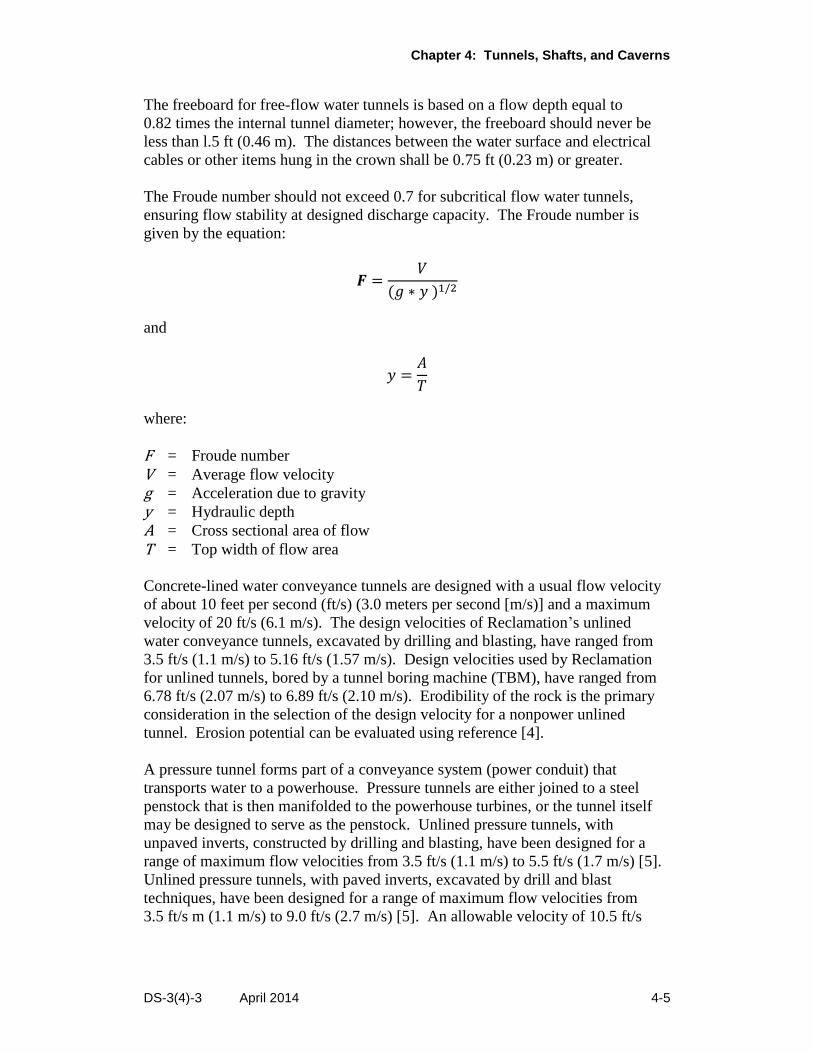
The Froude number should not exceed 0.7 for subcritical flow water tunnels,
ensuring flow stability at designed discharge capacity. The Froude number is
given by the equation:
𝑭 =𝑉
(𝑔 ∗ 𝑦 )1/2
and
𝑦 =𝐴
𝑇
where:
F = Froude number
V = Average flow velocity
g = Acceleration due to gravity
y = Hydraulic depth
A = Cross sectional area of flow
T = Top width of flow area
Concrete-lined water conveyance tunnels are designed with a usual flow velocity
of about 10 feet per second (ft/s) (3.0 meters per second [m/s)] and a maximum
velocity of 20 ft/s (6.1 m/s). The design velocities of Reclamation’s unlined
water conveyance tunnels, excavated by drilling and blasting, have ranged from
3.5 ft/s (1.1 m/s) to 5.16 ft/s (1.57 m/s). Design velocities used by Reclamation
for unlined tunnels, bored by a tunnel boring machine (TBM), have ranged from
6.78 ft/s (2.07 m/s) to 6.89 ft/s (2.10 m/s). Erodibility of the rock is the primary
consideration in the selection of the design velocity for a nonpower unlined
tunnel. Erosion potential can be evaluated using reference [4].
A pressure tunnel forms part of a conveyance system (power conduit) that
transports water to a powerhouse. Pressure tunnels are either joined to a steel
penstock that is then manifolded to the powerhouse turbines, or the tunnel itself
may be designed to serve as the penstock. Unlined pressure tunnels, with
unpaved inverts, constructed by drilling and blasting, have been designed for a
range of maximum flow velocities from 3.5 ft/s (1.1 m/s) to 5.5 ft/s (1.7 m/s) [5].
Unlined pressure tunnels, with paved inverts, excavated by drill and blast
techniques, have been designed for a range of maximum flow velocities from
3.5 ft/s m (1.1 m/s) to 9.0 ft/s (2.7 m/s) [5]. An allowable velocity of 10.5 ft/s
Design Standards No. 3: Water Conveyance Systems
4-6 DS-3(4)-3 April 2014
(3.20 m/s) was selected for design of an unlined tunnel constructed by a TBM [6].
Both erodibility of the rock and the cost of power are primary considerations in
the selection of design velocity for an unlined pressure tunnel.
Design Standard No. 14, Appurtenant Structures for Dams (Spillways and Outlet
Works) [7], gives design velocities for Reclamation spillway and outlet works
tunnels. Tunnels conveying water containing sand or gravel have high potential
for invert erosion [8]. Smooth flowing clear water will not damage good quality
concrete, even at high velocities, unless the velocity or direction of velocity is
abruptly changed or when surface irregularities or misalignment of joints reduce
the pressure in flowing water to its vapor pressure [8].
Cavitation damage may occur when flowing water contacts rough surfaces [9].
For example, at sea level, with a depth of flow of 8.0 foot (2.4 m), and a ¼-inch
(6.4 mm) offset, incipient cavitation would occur at an average velocity of
approximately 36 ft/s (11 m/s) [10].
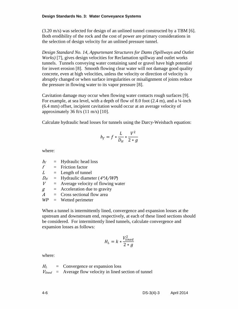
Calculate hydraulic head losses for tunnels using the Darcy-Weisbach equation:
ℎ𝑓 = 𝑓 ∗𝐿
𝐷𝐻∗
𝑉2
2 ∗ 𝑔
where:
hf = Hydraulic head loss
f = Friction factor
L = Length of tunnel
DH = Hydraulic diameter (4*A/WP)
V = Average velocity of flowing water
g = Acceleration due to gravity
A = Cross sectional flow area
WP = Wetted perimeter
When a tunnel is intermittently lined, convergence and expansion losses at the
upstream and downstream end, respectively, at each of these lined sections should
be considered. For intermittently lined tunnels, calculate convergence and
expansion losses as follows:
𝐻𝐿 = 𝑘 ∗𝑉𝑙𝑖𝑛𝑒𝑑
2
2 ∗ 𝑔
where:
HL = Convergence or expansion loss
Vlined = Average flow velocity in lined section of tunnel
Chapter 4: Tunnels, Shafts, and Caverns
DS-3(4)-3 April 2014 4-7
k = Coefficient of contraction or coefficient of expansion as appropriate
g = Acceleration due to gravity
The coefficient of contraction can be taken as varying linearly between 0.11,
for an angle between the tunnel axis and the upstream taper of the tunnel of
5.75 degrees (°), and 0.78, for a 45° angle (page. 3-20 in reference [11]) where
k = 1/C2 -1.
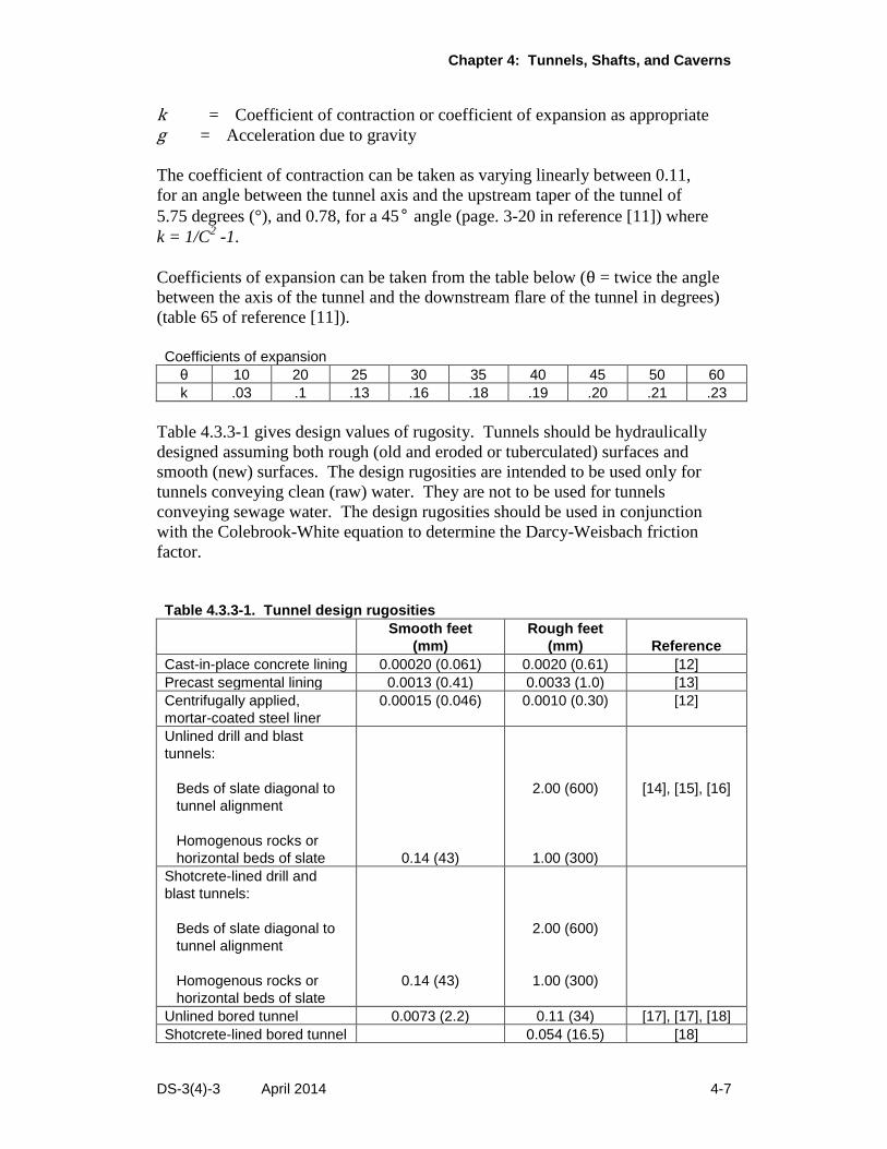
Coefficients of expansion can be taken from the table below (θ = twice the angle
between the axis of the tunnel and the downstream flare of the tunnel in degrees)
(table 65 of reference [11]).
Coefficients of expansion
θ 10 20 25 30 35 40 45 50 60
k .03 .1 .13 .16 .18 .19 .20 .21 .23
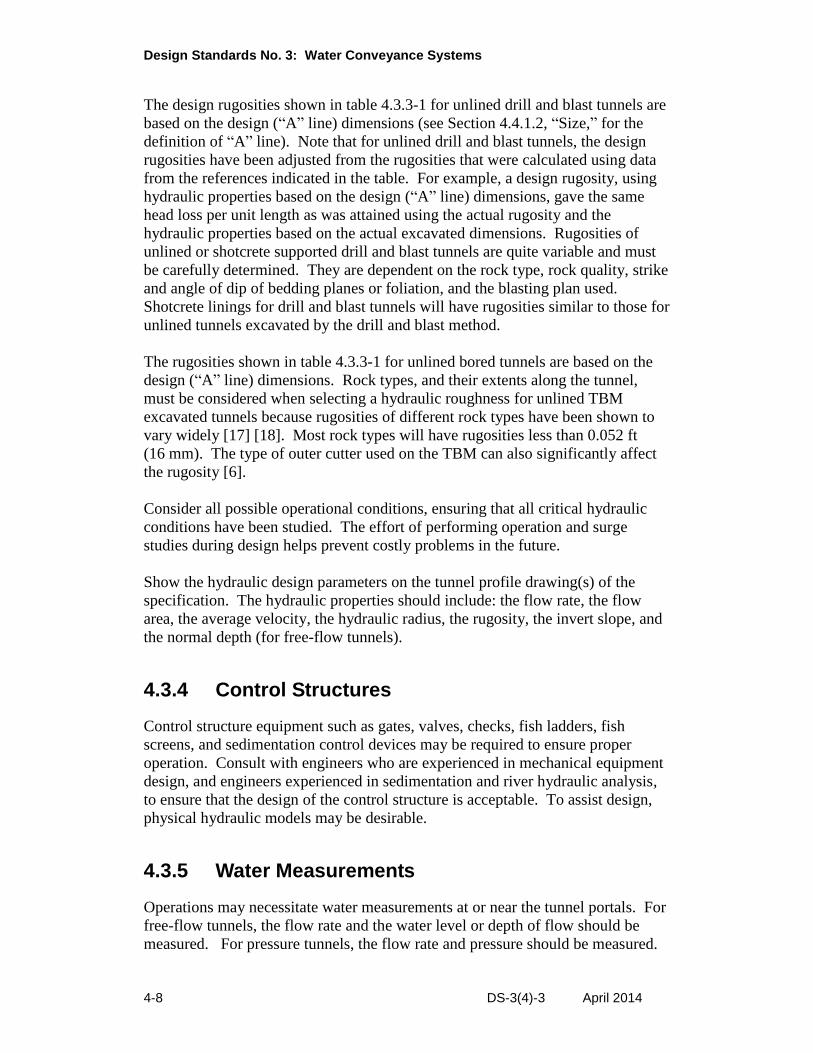
Table 4.3.3-1 gives design values of rugosity. Tunnels should be hydraulically
designed assuming both rough (old and eroded or tuberculated) surfaces and
smooth (new) surfaces. The design rugosities are intended to be used only for
tunnels conveying clean (raw) water. They are not to be used for tunnels
conveying sewage water. The design rugosities should be used in conjunction
with the Colebrook-White equation to determine the Darcy-Weisbach friction
factor.
Table 4.3.3-1. Tunnel design rugosities
Smooth feet
(mm)
Rough feet
(mm) Reference
Cast-in-place concrete lining 0.00020 (0.061) 0.0020 (0.61) [12]
Precast segmental lining 0.0013 (0.41) 0.0033 (1.0) [13]
Centrifugally applied,
mortar-coated steel liner
0.00015 (0.046) 0.0010 (0.30) [12]
Unlined drill and blast
tunnels:
Beds of slate diagonal to
tunnel alignment
Homogenous rocks or
horizontal beds of slate
0.14 (43)
2.00 (600)
1.00 (300)
[14], [15], [16]
Shotcrete-lined drill and
blast tunnels:
Beds of slate diagonal to
tunnel alignment
Homogenous rocks or
horizontal beds of slate
0.14 (43)
2.00 (600)
1.00 (300)
Unlined bored tunnel 0.0073 (2.2) 0.11 (34) [17], [17], [18]
Shotcrete-lined bored tunnel 0.054 (16.5) [18]
Design Standards No. 3: Water Conveyance Systems
4-8 DS-3(4)-3 April 2014
The design rugosities shown in table 4.3.3-1 for unlined drill and blast tunnels are
based on the design (“A” line) dimensions (see Section 4.4.1.2, “Size,” for the
definition of “A” line). Note that for unlined drill and blast tunnels, the design
rugosities have been adjusted from the rugosities that were calculated using data
from the references indicated in the table. For example, a design rugosity, using
hydraulic properties based on the design (“A” line) dimensions, gave the same
head loss per unit length as was attained using the actual rugosity and the
hydraulic properties based on the actual excavated dimensions. Rugosities of
unlined or shotcrete supported drill and blast tunnels are quite variable and must
be carefully determined. They are dependent on the rock type, rock quality, strike
and angle of dip of bedding planes or foliation, and the blasting plan used.
Shotcrete linings for drill and blast tunnels will have rugosities similar to those for
unlined tunnels excavated by the drill and blast method.
The rugosities shown in table 4.3.3-1 for unlined bored tunnels are based on the
design (“A” line) dimensions. Rock types, and their extents along the tunnel,
must be considered when selecting a hydraulic roughness for unlined TBM
excavated tunnels because rugosities of different rock types have been shown to
vary widely [17] [18]. Most rock types will have rugosities less than 0.052 ft
(16 mm). The type of outer cutter used on the TBM can also significantly affect
the rugosity [6].
Consider all possible operational conditions, ensuring that all critical hydraulic
conditions have been studied. The effort of performing operation and surge
studies during design helps prevent costly problems in the future.
Show the hydraulic design parameters on the tunnel profile drawing(s) of the
specification. The hydraulic properties should include: the flow rate, the flow
area, the average velocity, the hydraulic radius, the rugosity, the invert slope, and
the normal depth (for free-flow tunnels).
4.3.4 Control Structures
Control structure equipment such as gates, valves, checks, fish ladders, fish
screens, and sedimentation control devices may be required to ensure proper
operation. Consult with engineers who are experienced in mechanical equipment
design, and engineers experienced in sedimentation and river hydraulic analysis,
to ensure that the design of the control structure is acceptable. To assist design,
physical hydraulic models may be desirable.
4.3.5 Water Measurements
Operations may necessitate water measurements at or near the tunnel portals. For
free-flow tunnels, the flow rate and the water level or depth of flow should be
measured. For pressure tunnels, the flow rate and pressure should be measured.
Chapter 4: Tunnels, Shafts, and Caverns
DS-3(4)-3 April 2014 4-9
The flow rates of water encountered during construction must be frequently
measured and recorded. The quality of the water collected from a tunnel under
construction should be checked, and the water should be treated as required prior
to being discharged into the surrounding environment. Equipment design should
be coordinated with the appropriate specialty organization.
4.3.6 Ventilation
Ventilation includes heating, air-conditioning, filtration, and fire protection and is
governed by local codes and other applicable regulations. Current issues of
the American Society of Heating, Refrigeration and Air Conditioning Engineer’s
Handbooks (HVAC Applications, Fundamentals, Refrigeration and
HVAC Systems & Equipment) provide a complete reference on the subject.
The contractor is responsible for ventilation during construction and is governed
by Reclamation Safety and Health Standards [19].
Designs must provide ventilation for normal inspection and maintenance.
Tunnels, shafts, and caverns, not mechanically ventilated, are considered
confined spaces and must be treated as such. Where a tunnel, shaft, or cavern is
infrequently entered, the cost of permanent mechanical ventilation can be
weighed against the cost and inconvenience of temporarily ventilating a confined
space.
Consult mechanical engineers who are experienced in designing permanent
ventilation systems. The ventilation system is designed to comply with the Office
of Safety and Health Administration’s (OSHA) Standard 29 Code of Federal
Regulations (CFR) 1926.800. When designing these systems, a minimum of
200 cubic feet per minute of fresh outside air, per expected employee, must be
delivered to the space, although more may be required based on the application.
4.3.7 Lighting
Adequate lighting during construction must comply with Reclamation Safety and
Health Standards [23] and is the responsibility of the contractor. Water tunnels do
not require permanent lighting. Other structures, such as access adits, do require
permanent lighting. The Illuminating Engineering Society of North America gives
the lighting requirements for tunnels designed for various purposes [20].
Highway tunnel lighting requirements depend on several factors such as length,
geographic orientation, geometric design, traffic volume, vehicular speed, light
source, and modes of light application.
Consult electrical engineers who are experienced in the design of lighting
systems.
Design Standards No. 3: Water Conveyance Systems
4-10 DS-3(4)-3 April 2014
4.3.8 Safety
4.3.8.1 General
Design Standards No. 3 - Water Conveyance Facilities, Fish Facilities, and
Roads and Bridges, Chapter 13, “Safety Requirements,” addresses functional
design safety requirements for underground structures. Contractors are
responsible for safety during construction. Area offices are responsible for safety
during operation and maintenance, and they should ensure conformance with the
applicable Reclamation criteria.
4.3.8.2 Timber
Use of timber supports and/or wood lagging is currently prohibited by
Section 23.10.7 of Reclamation Safety and Health Standards [19]. A waiver of
Section 23.10.7 must be obtained where use of timber supports and/or lagging
is anticipated. All timber should be treated with fire retardant unless an
approved fire prevention or suppression system is provided. OSHA (Standard
No. 1926.800 (m) (12)) requires that all underground structures be constructed of
materials with a fire resistance rating of at least 1 hour.
4.4 General Design Considerations
4.4.1 Geometric Design
4.4.1.1 Shape
The most common shapes for Reclamation tunnels are circular, horseshoe, and
modified horseshoe. Other shapes, such as elliptical and rectangular, are not
common, but may be used if justified. Justification must include consideration
of possible increased concrete forming costs. Shafts are typically circular or
rectangular in shape.
Underground structures’ shapes are usually influenced by the intended function,
geology, geotechnical properties of the in situ ground, and the construction
method.
Considerations based on intended function include:
Free-flow water tunnels may be designed using any of the three common
shapes. The circular shape is best for pressure flow or power tunnels.
Access tunnels require a flat invert or floor; therefore, the modified
horseshoe shape is most appropriate. Other shapes with curved inverts can
be used but require building up the invert to level or providing a walkway.
Chapter 4: Tunnels, Shafts, and Caverns
DS-3(4)-3 April 2014 4-11
Highway and road tunnels require a relatively flat invert or road bed;
therefore, the modified horseshoe shape is most appropriate. Long highway
tunnels may require ventilation, lighting, and maintenance spaces that may
be accommodated better by other shapes, (e.g., circular).
Considerations based on geology and geotechnical properties include:
A benefit of the circular shape and the horseshoe shape is that loadings from
the ground or groundwater place the lining in compression. A circular
shape is usually the best shape to resist squeezing and swelling ground
loads, as well as external hydrostatic pressures.
Moments from ground and external hydrostatic loads can result in the
allowable tensile capacity of the concrete in the sidewall and the invert of
the lining of a modified horseshoe shape being exceeded, requiring concrete
reinforcement.
Considerations based on construction method include:
It is easier to drill, blast, and muck a horseshoe or modified horseshoe shape
than a circular shape.
Tunnel boring machines are limited to circular shapes. Similarly, bored
shafts are circular.
Roadheaders can excavate most shapes; however, it is easier to work on
flatter inverts.
Both unreinforced and reinforced concrete may be used to line all shapes of
tunnels. Precast concrete segments are generally used for circular tunnels
constructed by TBMs.
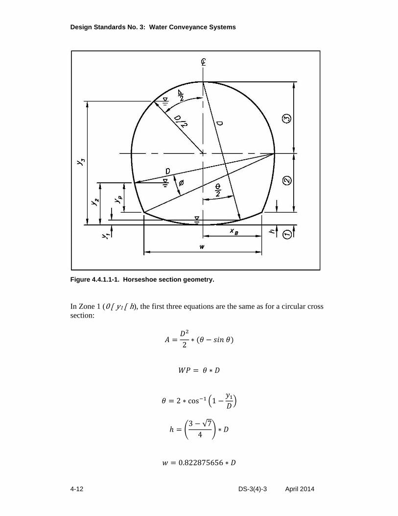
Computing hydraulic properties of circular sections and modified horseshoe
sections is straightforward. This is not true for the horseshoe cross section
(figure 4.4.1.1-1). The equations used to calculate the area and wetted perimeter
depend on the location of the water surface relative to the tunnel cross section.
The horseshoe section is divided into three zones. The region bounded by the
wetted perimeter of the tunnel and a water surface in the invert is defined as
Zone 1. The region bounded by the wetted perimeter of the tunnel and a water
surface above the invert and below or at the springline is defined as Zone 2. The
region bounded by the wetted perimeter of the tunnel and a water surface above
the springline is defined as Zone 3. As used above, “invert” is defined as the
curved floor of a tunnel [21], and “spring line” is defined as the meeting of the
roof arch and the sides of a tunnel [28].
Design Standards No. 3: Water Conveyance Systems
4-12 DS-3(4)-3 April 2014
Figure 4.4.1.1-1. Horseshoe section geometry.
In Zone 1 (0 y1 h), the first three equations are the same as for a circular cross
section:
𝐴 =𝐷2
2∗ (𝜃 − 𝑠𝑖𝑛 𝜃)
𝑊𝑃 = 𝜃 ∗ 𝐷
𝜃 = 2 ∗ cos−1 (1 −𝑦1
𝐷)
ℎ = (3 − √7
4) ∗ 𝐷
𝑤 = 0.822875656 ∗ 𝐷
Chapter 4: Tunnels, Shafts, and Caverns
DS-3(4)-3 April 2014 4-13
where:
y1 = The depth of flow when water surface is in Zone 1
D = As shown on figure 4.4.1.1-1
A = Area of flow
WP = Wetted perimeter
Θ = Angle as shown on figure 4.4.1.1-1, in radians
h = Height as shown on figure 4.4.1.1-1
w = Width as shown on figure 4.4.1.1-1
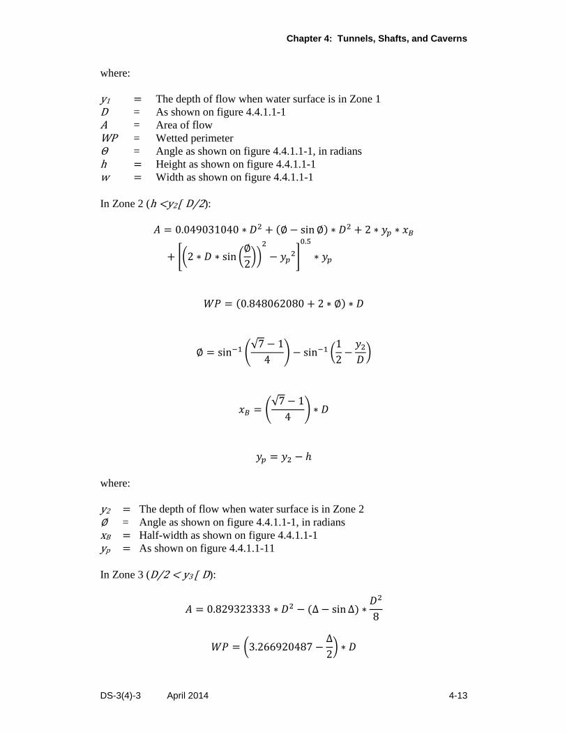
In Zone 2 (h <y2 D/2):
𝐴 = 0.049031040 ∗ 𝐷2 + (∅ − sin ∅) ∗ 𝐷2 + 2 ∗ 𝑦𝑝 ∗ 𝑥𝐵
+ [(2 ∗ 𝐷 ∗ sin (∅
2))
2
− 𝑦𝑝2]
0.5
∗ 𝑦𝑝
𝑊𝑃 = (0.848062080 + 2 ∗ ∅) ∗ 𝐷
∅ = sin−1 (√7 − 1
4) − sin−1 (
1
2−
𝑦2
𝐷)
𝑥𝐵 = (√7 − 1
4) ∗ 𝐷
𝑦𝑝 = 𝑦2 − ℎ
where:
y2 = The depth of flow when water surface is in Zone 2
∅ = Angle as shown on figure 4.4.1.1-1, in radians
xB = Half-width as shown on figure 4.4.1.1-1
yp = As shown on figure 4.4.1.1-11
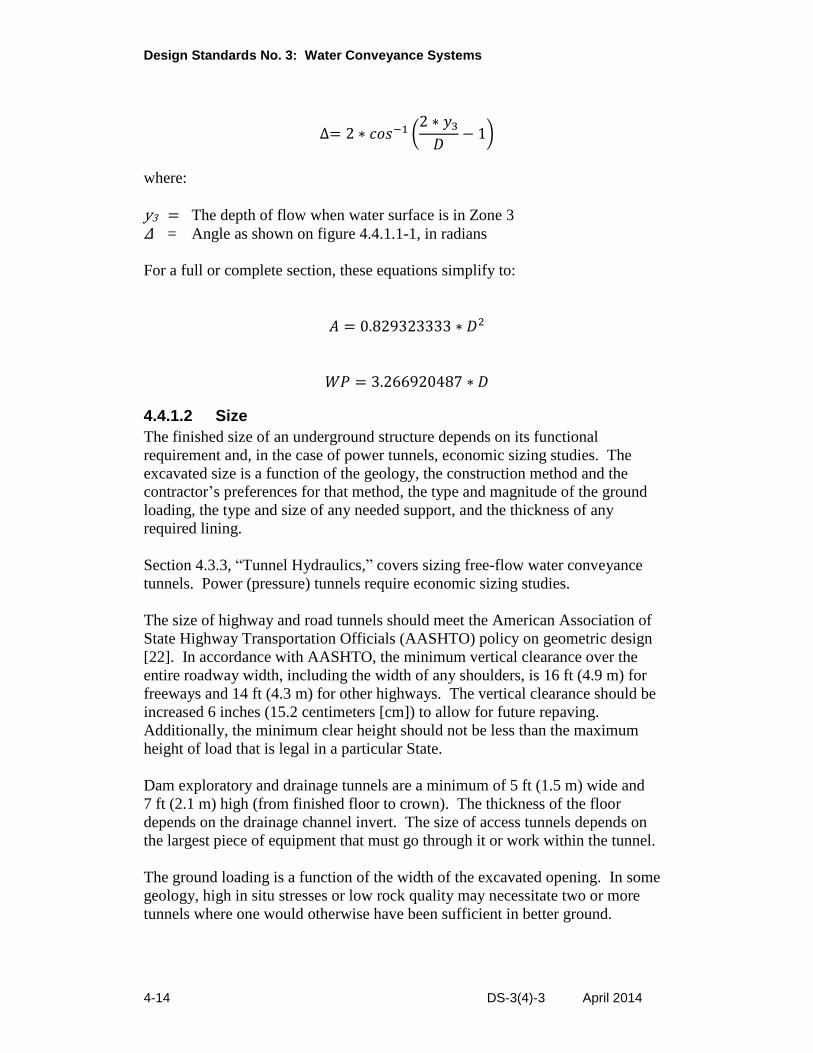
In Zone 3 (D/2 < y3 D):
𝐴 = 0.829323333 ∗ 𝐷2 − (∆ − sin ∆) ∗𝐷2
8
𝑊𝑃 = (3.266920487 −∆
2) ∗ 𝐷
Design Standards No. 3: Water Conveyance Systems
4-14 DS-3(4)-3 April 2014
∆= 2 ∗ 𝑐𝑜𝑠−1 (2 ∗ 𝑦3
𝐷− 1)
where:
y3 = The depth of flow when water surface is in Zone 3
Δ = Angle as shown on figure 4.4.1.1-1, in radians
For a full or complete section, these equations simplify to:
𝐴 = 0.829323333 ∗ 𝐷2
𝑊𝑃 = 3.266920487 ∗ 𝐷
4.4.1.2 Size
The finished size of an underground structure depends on its functional
requirement and, in the case of power tunnels, economic sizing studies. The
excavated size is a function of the geology, the construction method and the
contractor’s preferences for that method, the type and magnitude of the ground
loading, the type and size of any needed support, and the thickness of any
required lining.
Section 4.3.3, “Tunnel Hydraulics,” covers sizing free-flow water conveyance
tunnels. Power (pressure) tunnels require economic sizing studies.
The size of highway and road tunnels should meet the American Association of
State Highway Transportation Officials (AASHTO) policy on geometric design
[22]. In accordance with AASHTO, the minimum vertical clearance over the
entire roadway width, including the width of any shoulders, is 16 ft (4.9 m) for
freeways and 14 ft (4.3 m) for other highways. The vertical clearance should be
increased 6 inches (15.2 centimeters [cm]) to allow for future repaving.
Additionally, the minimum clear height should not be less than the maximum
height of load that is legal in a particular State.
Dam exploratory and drainage tunnels are a minimum of 5 ft (1.5 m) wide and
7 ft (2.1 m) high (from finished floor to crown). The thickness of the floor
depends on the drainage channel invert. The size of access tunnels depends on
the largest piece of equipment that must go through it or work within the tunnel.
The ground loading is a function of the width of the excavated opening. In some
geology, high in situ stresses or low rock quality may necessitate two or more
tunnels where one would otherwise have been sufficient in better ground.
Chapter 4: Tunnels, Shafts, and Caverns
DS-3(4)-3 April 2014 4-15
When tunneling through squeezing or swelling ground, excavation dimensions
are given special attention and are determined on a case-by-case basis. For
guidance on drill and blast mining through squeezing or swelling ground, see
reference [23]. For considerations on TBM tunneling through squeezing or
swelling ground, see reference [24]. When unexpected squeezing or swelling
ground is encountered during construction, the cross section of a tunnel excavated
by drilling and blasting can be increased to allow for inward deformation of
the ground, unlike the diameter of the bore excavated by a TBM, which is
predetermined. If a significant length of a tunnel to be excavated by a TBM is
expected to be in squeezing or swelling ground, then selecting a larger diameter
bore could be considered.
The maximum width of hand-mined soil tunnels is about 63 ft (19.2 m). Caverns
with a 203-ft (62-m) span have been excavated in rock. To date, the largest
size tunnel excavated by a soft ground TBM is 57.5 ft (17.5 m). The present
maximum size of a tunnel excavated by a rock TBM is 47.2 ft (14.4 m). Tunnels
as small as approximately 6.6 ft (2 m) can be excavated in rock or soft ground by
TBMs. Small boring machines between 4.5 ft (1.4 m) and 6.5 ft (2.0 m) can
excavate limited distances. Pipes as small as 20 inches (50 cm) in diameter can
be installed limited distances by the microtunneling method.
Designers should consider allowing, at the contractor’s option, a larger finished
tunnel size than is functionally required, but at no additional cost to the
Government. Tunnels that are larger than originally specified in the design must
meet all the required criteria of the designed tunnel. The designer should consider
probable sizes during design and may state the maximum sizes allowed in the
specifications.
The size of the excavation must accommodate the thickness of the lining and any
needed support system beyond the finished dimensions.
The finished dimension of unlined tunnels should be 8 ft 0 inch (2.4 m) or larger,
and lined tunnels should be 7 ft 0 inch (2.1 m) or larger.
The “A” line dimension defines the minimum limits of an excavation, as
discussed in Section 4.7.2.2, “Minimum Thickness.” The “B” line is the payline
when tunnel excavation is paid for by the cubic yard. The “A” line to “B” line
dimension is predicated on providing sufficient space for the expected support
system (including lagging where steel sets are specified) and allowing for
reasonable overbreak beyond the minimum excavation theoretically required for
the installed support system.
The procedure for determining the dimension between the “A” line and “B” line
was previously quite elaborate. It was a function of “A” line diameter, tunnel
shape, installed support, and excavation method. Basing the dimension on so
many factors led designers to believe that it was a precise and important
Design Standards No. 3: Water Conveyance Systems
4-16 DS-3(4)-3 April 2014
dimension, which it is not. Although based on historical data [25], the predicted
amount of overbreak is limited to the specific geology and rock quality of the
tunnels studied, and it only provides an estimate for tunnels constructed in other
geology and rock quality. Additionally, the contractor typically chooses to
excavate the ground to other than the “B” line (payline).
Unit price bidding gave the contractor incentive to submit an unbalanced bid and
to install structural steel supports where they were clearly not required to support
the ground. Paying for the excavation and support of the tunnel by the linear foot
of tunnel (for a given rock classification) and simplifying the method for
determining the “B” line alleviate these problems. When per linear foot bidding
is used, the “B” line only serves to provide reasonable quantities of excavation for
estimating purposes and can otherwise be eliminated from the specifications.
Establishment of a per linear foot pay option should be a team decision. A
common “B” line throughout a tunnel may also be an option.
Roadheader or drill and blast excavated tunnels with finished diameters between
7 ft and 20 ft (2 m and 6 m) have “A” line to “B” line dimensions of 16 inches
(40.6 cm). Tunnels with finished diameters between 20 ft and 50 ft (6 m and
15 m) have “A” line to “B” line dimensions of 18 inches (45.7 cm).
The minimum bore (excavated) diameter for unsupported or rock-bolted TBM
tunnels is the “A” line dimension plus 8 inches (200 mm). For rib-supported
TBM tunnels, it is the “A” line dimension plus 12 inches (300 mm).
4.4.1.3 Gradient
Reclamation water tunnels usually have very gentle, constant slopes. The
minimum tunnel slope is 0.0001, based on drainage. Tunnel reaches less than
100 ft (30 m) long may be flat. The minimum slope for free-flow tunnels is
usually based on hydraulics but should never be less than 0.0001. The
maximum slope for free-flow tunnels is based on Froude number as explained
in Section 4.3.3, “Tunnel Hydraulics.”
Permanent access tunnel grades should never be greater than 10%. Construction
adit grades may be up to 18%. Steep grades usually reduce access tunnel length
but greatly increase unit construction costs.
The practical limit of grade for muck handling depends on equipment and is
3% for steel rail equipment, 10% for rubber-tired equipment, and 36% for belt
conveyors. A slusher (cable-assisted box-type scraper) can be used for grades to
about 58% when excavating upslope and with no limitation of grade when
excavating downslope. Grades around 100% and steeper are considered self-
mucking.
Chapter 4: Tunnels, Shafts, and Caverns
DS-3(4)-3 April 2014 4-17
4.4.1.4 Horizontal Curves
Straight tunnel alignment is preferred, but bends are sometimes required. To
ensure the movement of locomotives and cars with long wheel bases, along
curves with widely spaced rails, without binding, the centerline radius of curves
should not be less than 50 ft (15 m). The minimum bend radius of a tunnel
conveying water is three times (four times preferred) the finished diameter of the
tunnel. The minimum radius for open shield driven tunnels is 600 ft (183 m) (see
Chapter 6 of reference [26]). The minimum radius required for tunnels excavated
by a TBM varies slightly with the size of the TBM. For example, a minimum
radius of 500 ft (152 m) would be required for a 10-ft- (3.0-m-) diameter TBM,
while a minimum radius of 600 ft (183 m) would be required for a 20-ft- (6.1-m)
diameter TBM. For tunnels that use a continuous belt conveyor system to remove
the muck, a minimum radius of 900 ft (274 m) would be required. If it is assumed
that a continuous belt conveyor system will be used, then in order to minimize
energy consumption, any required curve(s) in the tunnel alignment should be
located as far away from the portal (where the tunnel muck will be removed) as
practical.
4.4.1.5 Typical Sections
The “A” line is the line (shown on the typical tunnel sections of the specification
drawings) within which no unexcavated material of any kind (i.e., timbering,
metallic, or other support elements) shall be permitted to remain. However,
structural steel rib supports, steel pipe spreaders, and tie rods may extend within
the “A” line if allowed by the designer.
If the bidding schedule unit for excavation in tunnel quantities is cubic yards, then
the “B” line is the payline for excavation. As such, the measurement for payment
for excavation of the tunnel will always be made to the “B” line, regardless of
whether the actual extents of the excavation fall inside or outside the “B” line and
regardless of the size of steel supports used.
If the bidding schedule unit for excavation in tunnel quantities is linear feet, then
the “B” line serves only as the average line of excavation used for estimating
material quantities, and the need to show it on the typical tunnel sections of the
drawings is at the designer’s discretion.
4.4.1.6 Deviations and Tolerances
For concrete-lined tunnels, the limits of departure (deviation) from established
alignment (centerline) should be +1 inch (25 mm). The limits of departure from
finished grade for short tunnels (length not exceeding 1,000 ft [300 m]) should be
+ 1/2 inch (12 mm). The limits of departure from finished grade for long tunnels
(length exceeding 1,000 ft [300 m]) should be +1 inch (25 mm). The limits of
variation of the specified inside dimension are +0.5 percent, provided that the
thickness of lining at any point is never less than that specified.
Design Standards No. 3: Water Conveyance Systems
4-18 DS-3(4)-3 April 2014
The invert of a cast-in-place tunnel lining is typically placed prior to the rest of
the lining. For tunnels conveying water, a cast-in-place invert should have a
U3 (steel troweled) finish with a corresponding T3 surface irregularity tolerance.
For tunnels that do not convey water, a cast-in-place invert should have a
U2 (floated) finish with a corresponding T3 surface irregularity tolerance (see
chapter VI of Reclamation’s Concrete Manual [27] for description of U2 and
U3 surfaces of concrete).
4.4.2 Ground Cover Requirements
For excavation purposes, the minimum cover over the tunnel is a function of the
rock quality. For very good rock quality, the cover should not be less than the
largest cross-sectional dimension of the tunnel. Portals of tunnels excavated in
rock of lesser quality should have increased cover. An open cut is usually more
economical where cover is less than two diameters in rock and three diameters
in soil. Caverns should have cover equal to or greater than the largest
cross-sectional dimension. Section 4.7.3.3, “Confinement,” discusses cover
related to pressure tunnels.
4.4.3 Ground Settlement
Subsidence of the ground surface must be considered and avoided when
excavating under existing structures. The amount of settlement is influenced
by the size and depth of the opening, soil properties, groundwater conditions,
method and speed of excavation, and method and timing of support installation.
Settlement is increased by large-sized openings, noncohesive soils, permanent
lowering of the groundwater table, slow rates of advance of the tunnel, slow or
delayed installation of supports, and loss of ground at the heading.
Based on elastic theory, the maximum settlement of the ground surface (in ft)
above a shield-driven tunnel in clay is given by the following equation (See
Eq. 7.9 in reference [28]):
𝑆𝑚𝑎𝑥 = (1 − 𝜈2) ∗ (𝑃 𝐸⁄ ) ∗ (4 ∗ 𝑟2 ∗ ℎ)/(ℎ2 − 𝑟2)
where:
Smax = Maximum settlement of the ground surface
ν = Poisson’s ratio of soil
P = External pressure on tunnel lining
E = Modulus of elasticity of soil
r = Radius of opening
h = Cover measured from tunnel springline
Chapter 4: Tunnels, Shafts, and Caverns
DS-3(4)-3 April 2014 4-19
If a tunnel is driven where there are no structures, then based solely on construction costs, the volume of the settlement trough per unit length of tunnel
should not exceed 50 percent of the excavated volume of the tunnel per unit length [29]. The risk of ground caving all the way (daylighting) to the surface should also be considered.
Numerical methods can also be used to predict settlement. Where practical, the use of earth pressure balance or slurry TBMs will minimize settlement.
4.4.4 Portals
Portals are entrance or exit sections of a tunnel that need special design considerations. Tunnel portals are designed to: (1) sustain the existing
overburden (frequently of highly weathered material), (2) prevent outside drainage water from entering the tunnel, and (3) create an acceptable visual effect.
Portals need to be supported and to have a canopy during construction ( see section 23.10.1 of reference[19]).
For portals excavated in hard and intact rock, a minimum of one tunnel diameter of cover can be considered. Typically, for portals excavated in rock of lesser quality, a minimum of two to three diameters of cover is necessary to develop the
ground arch. Economy usually dictates that the cover over the portals be at least 20 ft (6 m) or, preferably, two times the tunnel diameter in rock and 30 ft (9 m) or three times the tunnel diameter in soil. Ten-ft- (3-m-) wide benches that provide
for stages of construction for slope stability, and to retain rockfall and raveling material, are required every 30 ft (10 m) vertically at portals. Very wide portals require a transition section between the portal and the tunnel. The transition
design should be hydraulically efficient and structurally safe.
4.5 Codes and Manuals for Design
Except as noted, the following codes and manuals will be used for design:
The design of steel will conform to the American Institute of Steel
Construction (AISC) [30], except for the design of structural steel sets for initial support (see section 4.7.1.1.1) and the design of steel liners (see sections 4.7.3.5 and 4.7.3.6).
The design of reinforced concrete will conform to American Concrete
Institute (ACI) 350-06 [31].
The design of unreinforced concrete will conform to ACI 318-08 [32].
The design of prestressed concrete will conform to ACI 350-06 [31].
Design Standards No. 3: Water Conveyance Systems
4-20 DS-3(4)-3 April 2014
4.6 Design Loads
4.6.1 General
Ground and groundwater loads acting on initial support and final lining shall be
based on the “B” line.
Internal hydraulic loads acting on linings shall be based on:
The finished face for unreinforced linings
The “A” line for reinforced linings
The location of the impermeable membrane for such linings
4.6.2 Ground Classification Systems
Several ground classification systems are available to predict the support loading
or the required total support system. Ground classification systems for rock
are different from those for soil. Some rock classification systems used by
Reclamation are: Rock Quality Designation (RQD) [33], Rock Mass Rating
(RMR) [34], Rock Structure Rating (RSR) [35], Q [36], and Terzaghi’s [23]
classification systems. For soft ground tunneling, the Terzaghi soil classification
system [37] is used by Reclamation. Employ at least two classification systems
where possible. Compare their results to any analytical or numerical analysis
used.
4.6.3 Rock Tunnels
Rock tunnel initial support design falls into one of the two following categories:
(1) the initial support resists the total load, or (2) the initial support and rock
together share the total rock load as a composite system. The rock loading may
be due to loosening (gravitational), swelling, or squeezing loads.
4.6.4 Soil Tunnels
Shallow tunnels (cover between 1.0 (B + Ht) to 1.5 (B + Ht)) in cohesionless soil
are designed such that the supports resist the load from the full depth of cover:
𝑃𝑣 = 𝛾 ∗ 𝐻𝑑
where:
B = Excavated width of the tunnel
Ht = Excavated height of the tunnel (except Ht = 0 for a circular tunnel)
Chapter 4: Tunnels, Shafts, and Caverns
DS-3(4)-3 April 2014 4-21
Pv = Vertical pressure from overburden
γ = Average unit weight of soil above the roof of the tunnel
Hd = Height of soil above the roof of the tunnel
For deep tunnels (cover more than 1.5 (B + Ht)) in cohesionless soils, the value of
Hd (see table 7-2, reference [29]) in the above equation is taken as the lesser of
the actual cover or the effective height (between 0.3 (B + Ht) and 2.0 (B + Ht))
which is dependent on the characteristics of the soil, whether the tunnel is
above or below the groundwater table, and the dimensions and shape of the
tunnel.
Pressures increases from the swelling of clay have been estimated at
50,000 pounds force per square foot [23]. Tests should be performed on such
soils to obtain a competent value.
For cohesive soils, the stability number (N) is defined as:
𝑁 = (𝑃𝑧 − 𝑃𝑎)/𝑆𝑢
where:
Pz = Overburden pressure at tunnel centerline
Pa = Compressed air pressure above atmospheric pressure
Su = Undrained shear strength of the cohesive soil (usually one-half of
unconfined compressive strength of the clay)
If N is less than 4, no unusual tunneling difficulties would be expected; if N is
greater than 5, hand mining would become difficult; and if N is greater than 7,
steering a shield would become difficult (see chapter 5, reference [38]), and
compressed air tunneling methods may be required. Compressed air tunneling is
expensive, time consuming, and hazardous. In such cases, consider using special
ground stabilization techniques such as freezing or jet grouting.
Use of an earth pressure-balance (EPB) TBM or a slurry TBM should be
considered for either cohesive or cohesionless soil types, respectively.
4.6.5 Seismic Considerations
For tunnels in rock or reasonably stiff soils, the tunnels are constrained by and
move with the surrounding ground. Tunnels are not subject to significant
vibratory amplification as are surface structures. Tunnels have generally
performed better than above-ground structures during seismic events. For tunnels
in rock, no damage was found where the peak acceleration at the surface was less
than 0.19 g [39] (where “g” is the acceleration due to gravity), and no further
seismic analysis is typically required.
Design Standards No. 3: Water Conveyance Systems
4-22 DS-3(4)-3 April 2014
Design of typical water conveyance tunnels, shafts, and caverns should be based
on an earthquake with a 10-percent probability of exceedance in an exposure time
of 50 years (approximately a 475-year frequency). Tunnels associated with dams
or highways may require higher return periods because of the importance of the
structure.
The peak ground acceleration can be calculated using the “Java Ground
Motion Parameter Calculator” application found on the U.S. Geological Survey
Web site: <http://earthquake.usgs.gov/hazards/designmaps/javacalc.php>. For
tunnels in soil that are less than 100 ft deep, site adjustment of the peak ground
acceleration, similar to those found in AASHTO Load and Resistance Factor
Design (LRFD) [40], should be made. Other seismically related data, such as
peak ground particle velocity, effective wave propagation velocity (for shear
[S-wave], compressional [P-wave], and Rayleigh waves), and an accelogram,
should be included in the design data.
The analysis of underground structures should be based on the displacement/
deformation of the lining imposed by the ground or interaction of the ground and
structure. Tunnels shall be analyzed for axial (longitudinal), curvature, and
ovaling deformations.
Where the structure is flexible relative to the surrounding ground, such as tunnels
in rock or stiff soil, the axial and curvature strain can be analyzed by assuming the
structure experiences the same strains as the surrounding ground. The most
critical angle between the axis of the tunnel alignment and the direction of wave
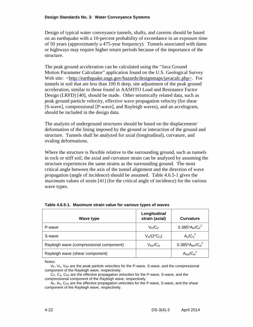
propagation (angle of incidence) should be assumed. Table 4.6.5-1 gives the
maximum values of strain [41] (for the critical angle of incidence) for the various
wave types.
Table 4.6.5-1. Maximum strain value for various types of waves
Wave type
Longitudinal
strain (axial) Curvature
P-wave VP/CP 0.385*AP/CP2
S-wave VS/(2*CS) As/CS2
Rayleigh wave (compressional component) VRP/CR 0.385*ARP/CR2
Rayleigh wave (shear component) ARS/CR2
Notes: VP, VS, VRP are the peak particle velocities for the P-wave, S-wave, and the compressional
component of the Rayleigh wave, respectively. CP, CS, CRP are the effective propagation velocities for the P-wave, S-wave, and the
compressional component of the Rayleigh wave, respectively. AP, AS, CRS are the effective propagation velocities for the P-wave, S-wave, and the shear
component of the Rayleigh wave, respectively.
Chapter 4: Tunnels, Shafts, and Caverns
DS-3(4)-3 April 2014 4-23
The allowable combined axial (longitudinal) and curvature strain of a linear
tunnel or underground structure should be less than a compressive strain of 0.002.
Tension cracks are acceptable when they do not adversely affect the tunnel’s
function or shorten the life of the structure.
Where a linear structure is located in soft soil, the structure will be relatively
stiffer (in the longitudinal direction) than the surrounding soil, and ground
deformations will be resisted by the lining. When a linear structure is located in
soft soil, making the assumption that the structure will have strains equal to those
of the surrounding ground, will produce unreasonable results. The internal
moments, shears, and axial forces for this case can be solved using numerical
methods [42], [43]. A simplified procedure [44] based on tunnel ground
interaction is recommended as a check of the numerical modeling.
Shear waves cause deformation of circular linings in the transverse direction
(ovaling). Analytical procedures by numerical methods can be used to determine
the diametric strain. The maximum allowable diametric strain, where the lining
has little stiffness relative to the ground, is given by the following equation:
∆𝐷
𝐷= ±2 ∗ 𝛾 ∗ (1 − 𝜇𝑚)
where:
ΔD = Maximum diametral deformation of the lining
D = Diameter of the tunnel
γ = Maximum free field shear strain (radians)
µm = Poisson’s ratio of the ground
and
𝛾 =𝑉𝑆
𝐶𝑆
where:
VS = Peak particle velocity
CS = Effective shear wave propagation velocity
When the lining has a stiffness equal to or greater than the ground, the maximum
allowable diametric strain is given by the following equation:
∆𝐷
𝐷= ±
𝛾
2
Design Standards No. 3: Water Conveyance Systems
4-24 DS-3(4)-3 April 2014
The numerical solution for diametric strain can be checked by the following
equation [44]:
𝜀𝑡𝑜𝑡𝑎𝑙 = 𝑉𝑠
𝐶𝑠∗ [3 ∗ (1 − 𝜇𝑚) ∗
𝑡
𝑅+
1
2∗
𝑅
𝑡∗
𝐸𝑚 ∗ (1 − 𝜇𝐿2)
𝐸𝐿 ∗ (1 + 𝜇𝑚)]
where:
εtotal = Maximum combined bending strain and thrust compression strain
μm = Poisson’s ratio of the ground (medium)
μL = Poisson’s ratio of lining material
t = Thickness of tunnel lining
R = Radius of tunnel
Em = Modulus of elasticity of the ground (medium)
EL = Modulus of elasticity of the tunnel lining
The potential for seismically related damage increases where: (1) an underground
structure passes through active fault zones, (2) a shallow tunnel is located in
rugged terrain or landslide areas, (3) a deep tunnel is in a highly pressurized rock
zone, or (4) ground or structure characteristics dramatically change, such as at the
portals. These situations should be carefully evaluated regardless of the
magnitude of the peak ground acceleration.
Seismic events can create ground shaking and ground failure. Types of ground
failure are faulting, landslides, liquefaction, and tectonic uplift and subsidence.
While attempts may be made to design for large fault movements, it is highly
recommended that tunnel alignments through active faults be avoided where
possible. While preventive measures against large-scale ground failure are
impractical, some preventive measures are possible against small-scale ground
failure. It is usually possible to design to accommodate ground shaking.
Protection against liquefaction should be provided for underground structures and
portals in soils vulnerable to severe strength loss as a result of ground shaking.
Protective measures against liquefaction are extremely sensitive to site conditions.
For controlling liquefaction, investigate densification, removal and replacement
of existing soil with clay-rich soil, or installation of drainage systems. In near-
surface underground structures, existing soil can be made denser by dynamic
compaction. For deep underground structures, consider applying compaction
grouting or chemical grouting to control liquefaction.
4.6.6 Shafts
Shaft design must include provisions for stability of the opening against both
horizontal and vertical movements. Selecting the proper construction method,
initial support and final lining for a shaft is dependent on the ground
Chapter 4: Tunnels, Shafts, and Caverns
DS-3(4)-3 April 2014 4-25
characteristics, the groundwater, as well as the shape, size and depth of the shaft.
Vertical stability of the lining may be achieved by supporting it on pillars or
foundation blocks, by hanging it from a collar (ring) beam on the surface, or
keying or anchoring it to the ground. Construction methods and initial support
of shafts excavated in soft ground include:
Soldier piles and lagging or steel plates
Liner plate with horizontal steel sets
Horizontal steel sets and vertical lagging
Sheet piles with horizontal steel sets
Corrugated metal or steel casing used with drilled shafts
Secant piles
Cutter soil mixing
Slurry walls
Freezing
Cast in place concrete caisson
Precast segmental concrete caisson
Initial support of shafts excavated in hard rock includes:
Steel sets with liner plate
Steel sets with lagging
Rock bolts with wire mesh
Shotcrete
Cassions can also be used in hard rock conditions
4.6.7 Caverns
Exploration adits are usually necessary for conducting geotechnical investigations
to determine the magnitudes and orientations of the principal stresses, and to
explore for anomalies that are not otherwise detectable. For deep exploration,
Design Standards No. 3: Water Conveyance Systems
4-26 DS-3(4)-3 April 2014
where construction of an adit is not practical, rock stress can be estimated using a
method of hydraulic fracturing or strain gages down a borehole. Thorough
exploration is critical for cavern design, as undetected anomalies can negate an
otherwise good design. Designers never know for sure what rock is present until
it is encountered. Careful geologic evaluation during excavation is important.
Caverns should be located in favorable geology. If the magnitudes of the
horizontal in situ principal stresses differ significantly, the cavern should be
oriented so that its longest dimension is parallel to the direction of the larger
horizontal in situ principal stress, if possible. Orienting the longest cavern
dimension parallel to the direction of the larger horizontal principal stress
minimizes the loading on the supports. The designer must weigh the problems
such an orientation alleviates against higher design and construction costs.
Three-dimensional analyses, such as analytical, numerical, photoelastic, or model
simulation, are normally used in cavern design.
4.6.8 Intersections
Analyses of intersections are conducive to numerical design methods.
Finite element analyses are useful for geometrically intricate intersections.
Alternatively, although more expensive and time consuming than numerical
methods, model analyses and photoelastic analyses (currently less common) could
be used. Other methods may be used where appropriate.
In finite element analyses, the model dimensions should not be less than three
times the largest cross-sectional dimension of the opening in any direction from
the intersection.
4.6.9 Adjacent Tunnels
Excavation of an underground opening may result in increased stresses (expressed
by stress concentration factors) around existing adjacent openings. It has been
found [45] that if a pillar between two adjacent openings is equal to or greater
than the sum of the diameters of the adjacent openings, there are usually no
increases in stresses or deformation compared to those of a single opening.
4.7 Support Systems
The selection and design of the support and lining are dependent on the in situ
pressures and stresses, geological and engineering characteristics of rock or soil,
standup time, and selected excavation methods. For competent rock, no support
is required from a structural point of view. Rock reinforcement, structural steel,
shotcrete, steel liner plates, and precast concrete segments are commonly used for
initial support.
Chapter 4: Tunnels, Shafts, and Caverns
DS-3(4)-3 April 2014 4-27
Historically, the final lining for Reclamation water conveyance tunnels has
usually been a cast-in-place concrete lining, although precast concrete segmental
linings have also been used in tunnels constructed by tunnel boring machines.
Precast concrete segments can sometimes serve as both initial support and final
lining (one-pass system), and eliminate the need for an additional cast-in-place
lining (two-pass system), which can result in significant cost savings. Steel
linings may be required in the reaches of a power tunnel near the portals and in
pressurized portions of outlet works tunnels downstream of the gate chamber near
the dam axis. Lining may not be required in competent rock.
4.7.1 Initial Support and Ground Control
4.7.1.1 Structural Steel Supports
4.7.1.1.1 Steel
The design of structural steel used as initial support shall be based on American
Society for Testing of Materials (ASTM) A 36 steel. A 992 steel meeting the
requirements of A 36 steel may be substituted when A 36 is not practically
available; however, the design will still be based on A 36 steel. The allowable
section is the wide flange section (AISC W shape). The allowable axial and
bending stresses for initial support structural steel sections are 0.75 Fy, where Fy is
the yield strength of the steel. The allowable shear stress for initial support steel
sections is 0.4 Fy.
4.7.1.1.2 Spacing
The standard spacing of structural steel supports for reaches of tunnels with light
rock loads is 5 ft (1.5 m) to 6 ft (1.8 m), with moderate rock loads is 4 ft (1.2 m),
and with heavy rock loads is 2 ft (0.6 m) to 3 ft (0.9 m). The minimum spacing
for structural steel supports in all tunnels is 1 ft (300 mm) between flanges. The
usual practice is to pick a spacing and design a shape that resists the loads.
Structural steel support spacing is usually a function of the rock quality and
associated rock loads, the steel shape size, and the maximum size of the steel
shape that can be bent to the required radius. Both the cost of the steel supports
and the cost of the lagging between these supports must be considered to
determine the most economical spacing.
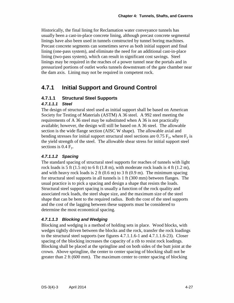
4.7.1.1.3 Blocking and Wedging
Blocking and wedging is a method of holding sets in place. Wood blocks, with
wedges tightly driven between the blocks and the rock, transfer the rock loadings
to the structural steel supports (see figures 4.7.1.1.6-1 and 4.7.1.1.6-23). Closer
spacing of the blocking increases the capacity of a rib to resist rock loadings.
Blocking shall be placed at the springline and on both sides of the butt joint at the
crown. Above springline, the center to center spacing of blocking shall not be
greater than 2 ft (600 mm). The maximum center to center spacing of blocking
Design Standards No. 3: Water Conveyance Systems
4-28 DS-3(4)-3 April 2014
shall be 1 ft (300 mm) before using jump sets. Blocking is not required with
expanded ribs, provided that the ribs contact the rock at least every 2 ft (600 mm).
4.7.1.1.4 Bend Radius of Cold Formed Steel Ribs
The minimum radius that 4-inch- and 6-inch-deep structural steel shapes can be
cold bent is eight times the depth of the section. The minimum radius that larger
structural steel shapes can be cold bent varies from 10 to 14 times the depth of the
section.
4.7.1.1.5 Spreaders and Tie Rods
Spreaders and tie rods are used to stabilize the structural steel support about its
minor axis. Their spacing should be determined by design. The maximum
spacing is 60 times the radius of gyration about the minor axis 23].
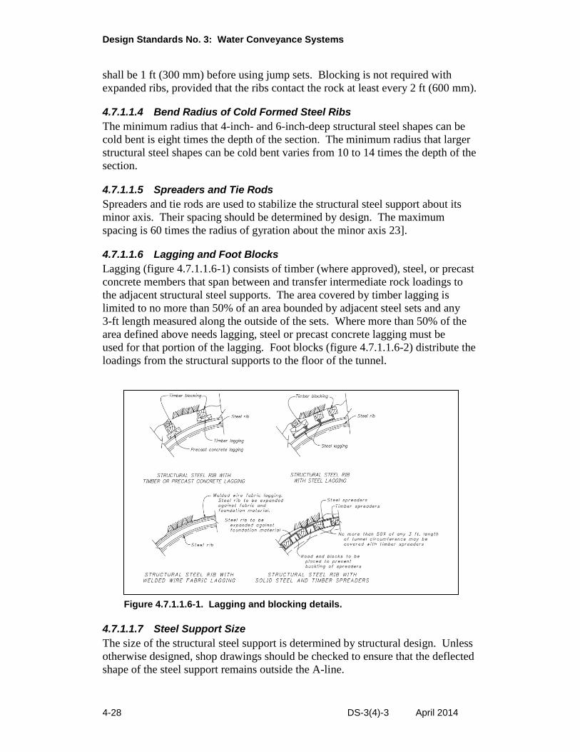
4.7.1.1.6 Lagging and Foot Blocks
Lagging (figure 4.7.1.1.6-1) consists of timber (where approved), steel, or precast
concrete members that span between and transfer intermediate rock loadings to
the adjacent structural steel supports. The area covered by timber lagging is
limited to no more than 50% of an area bounded by adjacent steel sets and any
3-ft length measured along the outside of the sets. Where more than 50% of the
area defined above needs lagging, steel or precast concrete lagging must be
used for that portion of the lagging. Foot blocks (figure 4.7.1.1.6-2) distribute the
loadings from the structural supports to the floor of the tunnel.
Figure 4.7.1.1.6-1. Lagging and blocking details.
4.7.1.1.7 Steel Support Size
The size of the structural steel support is determined by structural design. Unless
otherwise designed, shop drawings should be checked to ensure that the deflected
shape of the steel support remains outside the A-line.
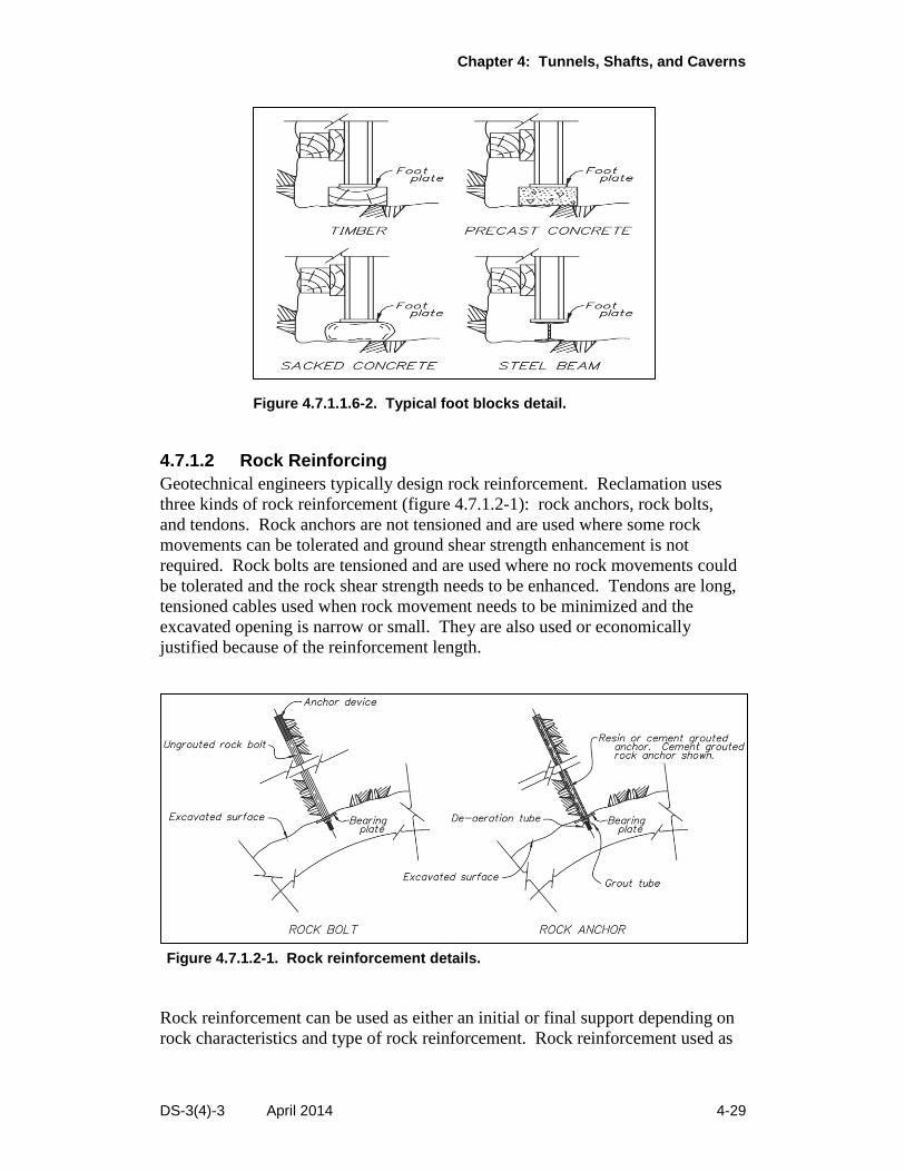
Chapter 4: Tunnels, Shafts, and Caverns
DS-3(4)-3 April 2014 4-29
Figure 4.7.1.1.6-2. Typical foot blocks detail.
4.7.1.2 Rock Reinforcing
Geotechnical engineers typically design rock reinforcement. Reclamation uses
three kinds of rock reinforcement (figure 4.7.1.2-1): rock anchors, rock bolts,
and tendons. Rock anchors are not tensioned and are used where some rock
movements can be tolerated and ground shear strength enhancement is not
required. Rock bolts are tensioned and are used where no rock movements could
be tolerated and the rock shear strength needs to be enhanced. Tendons are long,
tensioned cables used when rock movement needs to be minimized and the
excavated opening is narrow or small. They are also used or economically
justified because of the reinforcement length.
Figure 4.7.1.2-1. Rock reinforcement details.
Rock reinforcement can be used as either an initial or final support depending on
rock characteristics and type of rock reinforcement. Rock reinforcement used as
Design Standards No. 3: Water Conveyance Systems
4-30 DS-3(4)-3 April 2014
final support must have a projected life at least as long as the life of the project.
Fully grouted reinforcement will usually provide this life. Epoxy-coated steel or
fiberglass rock bolts may be used in corrosive environments.
Spot or pattern rock reinforcement can be used by itself or in combination with
metal straps (mine roof mats), chain link fabric, welded-wire fabric, and shotcrete.
Typical reinforcing patterns range from 2-ft by 2-ft (0.6-m by 0.6-m) to 6-ft by
6-ft (1.8-m by 1.8-m). Reinforcement should be placed to span over prominent
joints.
Solid or groutable hollow rock bolts or anchors, and rock stabilizers (e.g., Split
Sets® or Swellex®) can be designed to sustain the load using principles of
(1) suspension, (2) arching, or (3) beam theory [46].
In suspension theory, the weight of a critical (key block) and potentially unstable
rock block is carried by a single bolt or multiple bolts with a usual factor of safety
of 2. In arching theory, at an indeterminate height above an opening, an arch
forms as a result of stress redistribution following excavation of the opening. Any
loosened rock between the crown or roof of the opening and this natural arch must
be supported. For heavily jointed rock, by using rock bolts in conjunction with
shotcrete or mesh, an artificial arch near the crown or roof of the opening carries
the loosened rock loading. In beam theory, the rock and the bolts form a
laminated beam which carries the rock load. Rock bolts increase the shear
capacity of the laminated rock beam.
The minimum length of rock reinforcement for arch theory is the greatest of the
following:
1. Two times the bolt spacing.
2. Three times the width of critical and potentially unstable rock blocks.
3. One-half of the span of the opening for openings up to 20 ft (6 m).
4. One-fourth of the span for openings between 60 ft (18 m) and 100 ft
(30 m).
5. One-half to one-fourth of the span for openings between 20 ft ( 6 m) and
60 ft (18 m), respectively.
Maximum spacing of rock reinforcement is the least of the following:
1. One-half the length of bolt.
2. One and one-half times the width of critical and potentially unstable rock
blocks.
Chapter 4: Tunnels, Shafts, and Caverns
DS-3(4)-3 April 2014 4-31
3. Six ft (1.8 m).
The minimum spacing of rock reinforcement is 2 ft (0.6 m).
4.7.1.3 Shotcreting
Shotcrete can be used as either an initial or a final support. A 1.5-inch-thick layer
(38 mm) of shotcrete may be specified as a protective coating to preserve rock
surfaces subject to slaking and is considered not to carry any load. Support
shotcrete must be 3 inches (76 mm) thick or greater.
The usual Reclamation specified compressive strength is 3,000 pounds per square
inch (lb/in2) (21 megapascals [MPa]); however, the designer may specify higher
strengths. Current industry standard strengths are 4,000 lb/in2 tested at 28 days.
Testing for shotcrete strengths is typically done using test panels instead of cast
cylinders.
4.7.1.4 Grouting
Cement, microsilica, pozzolan, and foam grouts can be used for ordinary,
consolidation, compaction, jet, and pressure grouting. Chemical grout is used for
special purposes such as stabilizing soil or cutting off water. Grout life is highly
dependent on geological and hydrogeological factors. Some chemical grouts are
short lived. Cement grouts should not be used in a low pH (4 or less)
environment.
4.7.1.5 Freezing
Freezing is a costly method of ground stabilization that is most appropriate where
the dewatering or grouting of a cohesionless soil is not feasible. When freezing is
planned as a method for tunnel, shaft, or cavern excavation, the amount of heave
that is likely to occur should be properly controlled. Ground freezing in areas
containing steam, water, or sewage lines should be avoided, as insulating these
utility lines significantly increases the costs.
4.7.1.6 New Austrian Tunneling Method
The New Austrian Tunneling Method (NATM) has not been specified by
Reclamation; thus, no standards exist. Some of its elements such as shotcreting,
rock bolting, and observation by use of closure points have been incorporated into
Reclamation designs.
4.7.2 Final Lining
4.7.2.1 General
The functions of final (permanent) tunnel linings can be one or more of the
following:
Design Standards No. 3: Water Conveyance Systems
4-32 DS-3(4)-3 April 2014
Maintain the long-term (design life) structural integrity of the tunnel for
external or internal loadings
Provide a smoother hydraulic surface than that of an unlined tunnel
Prevent decomposition of erosive rock
Minimize water loss through exfiltration
Limit infiltration of deleterious water and contaminant
Provide a roadbed for vehicular travel
4.7.2.2 Minimum Thickness
The minimum thickness of an unreinforced concrete lining is measured from the
inside face of the concrete lining to the “A” line and is dependent on the method
of excavation. For drill and blast excavated tunnels, the minimum lining
thickness should equal 3/8 inch (10 mm) to 1/2 inch (13 mm) per foot of internal
tunnel diameter but not less than 4 inches (100 mm). For roadheader excavated
tunnels, the minimum lining thickness is 1 inch (25 mm) more than if the tunnel
were excavated by drill and blast methods. The minimum lining thickness for
TBM excavated tunnels is the same as for roadheader excavated tunnels but not
less than 6 inches (150 mm) if expanded ribs are used. The smaller minimum
lining thickness for the drill and blast method of excavation is allowed because
greater overbreak is anticipated with only isolated points of rock protruding to the
“A” line.
Ordinarily, because of a dam’s importance, the minimum thickness of concrete
linings associated with dam tunnels (e.g., diversion, spillway, and outlet works
tunnels) is twice (3/4 inch to 1 inch per foot of internal diameter) that of other
drill and blast excavated tunnels and should not be less than 6 inches [47]. Tunnel
linings associated with dams are frequently reinforced.
For reinforced concrete lining, the minimum cover over the reinforcement on the
ground side is 3 inches (75 mm). The minimum cover over the reinforcement on
the opening side is 2 inches (50 mm) for No. 8 or smaller bars, and 3 inches
(75 mm) for No. 9 or larger bars. Temperature and shrinkage reinforcement is
based on the “B” line or minimum bore diameter.
4.7.2.3 Loadings
Lining calculations must account for existing geological conditions including
anomalies such as shear zones intercepting the tunnel alignment at a skew angle,
ground loads, internal and external hydrostatic pressures, loadings from backfill
and ring grouting, tensile strength of concrete for unreinforced linings, and
reinforcement. Final lining structural design should ignore the strength
Chapter 4: Tunnels, Shafts, and Caverns
DS-3(4)-3 April 2014 4-33
contribution of initial supports. Final lining loading and design are based on
“A” line dimensions. Initial support loadings and design are based on “B” line
dimensions.
Segmental linings support the ground during and after construction. Segmental
lining design must include consideration of the following: loads from storage
(stacking) of the segments, loads from handling and installation (lifting) of the
segments, single shield TBM thrust forces during the mining cycle, grouting
pressures, and ground loads.
It is important to ensure that the rock above the crown of the tunnel will not
loosen and to avoid point loadings on the lining. Backfill grouting (see
figure 4.7.5-1) at 15 to 30 lb/in2 (100 to 210 kilopascals [kPa]) above existing
external water pressure is used to fill any voids above the crown not filled during
placement of the lining concrete. Filling these voids ensures uniform distribution
of the ground loading. Unless unusual grouting procedures are specified, lining
should be designed to withstand the grout pressure of 30 lb/in2 (210 kPa) over the
upper 90º of tunnel lining applied at the “A” line.
4.7.2.4 Water Tightness Design
Tunnels may or may not be designed for water tightness. Most water tunnels
designed to convey irrigation water are designed assuming that water leaks into
and out of the tunnel. Potable water tunnels must not allow any infiltration.
Waterproofing requirements of highway and access tunnels depend on their
particular use.
Water can infiltrate or exfiltrate through lining joints. Steel liner joints are
welded and watertight. Joint water tightness is ensured through nondestructive
testing or pressure testing. There are several joint types in a concrete lining:
construction, contraction, control, and expansion. These joints can be sources of
infiltration or exfiltration. The joints can be made waterproof to some degree. In
some cases, with proper design and construction control, 100% water tightness
can be obtained.
A lining can be waterproofed externally or internally. External waterproofing
uses an impervious membrane, preferably a thermoplastic seal, which is installed
at the lining-ground interface. In the internal method of waterproofing the lining,
the impervious membrane is installed at the innermost face of the lining or is
sandwiched between the outer and inner lining layers. Any sealing method must
be tested in place.
Individual joints in a concrete lining are waterproofed using waterstops, gaskets,
sealants, or caulking compounds. Waterstop joints can be sources and locations
of long-term deterioration and should be avoided if possible. The proper
embedment of water stops (at least 3 inches [75 mm]) ensures effective
performance.
Design Standards No. 3: Water Conveyance Systems
4-34 DS-3(4)-3 April 2014
4.7.2.5 Cracking of Concrete Tunnel Lining
Allowable crack widths depend on the functional requirements of the tunnel, the
geology, and the environmental exposure. In addition to a loss of conveyed
water, seepage through cracks in the lining of a pressure tunnel can result in lining
instability, slope stability failures, and hydrofracturing. A crack width of
0.01 inch (0.25 mm) can pipe silt and sand into the tunnel under 2 lb/in2
(0.014 MPa) of pressure [48].
Use of steel reinforcement in concrete will not stop cracking of the concrete;
however, well distributed reinforcement, within the area of maximum tensile
stress, will result in more cracks of reduced width instead of a few large cracks
[49]. Where a concrete lining of a pressure tunnel is to be reinforced to resist
tensile hoop stresses, the crack width and accompanying leakage are minimized
by use of reduced reinforcement stresses (see section 4.7.3.4.). Where absolute
water tightness is required, a steel lining or other impermeable lining should be
used. To determine the distribution of reinforcement, where a concrete lining is
designed to resist flexural stresses, the maximum allowable stress in the
reinforcement at service loads will be selected according to the appropriate
environmental exposure condition. ACI 350 [31] defines normal environmental
exposure as exposure to liquids with a pH greater than 5, or exposure to sulfate
solutions of 1,000 parts per million or less. Severe environmental exposures are
conditions that exceed these limits. The environmental exposure should consider
both the quality of the water conveyed and the quality of the groundwater
encompassing the tunnel.
The area and distribution of shrinkage and temperature reinforcement shall be in
accordance with section 7.12 of ACI 350. The thickness of the concrete section
for design shall be the distance from the finished surface of the lining to the
“B” line (see Section 4.4.1.2, “Size”) for the definition of “B” line.
4.7.3 Pressure Tunnels
4.7.3.1 General
Pressure tunnels are tunnels that convey water with a hydraulic gradeline above
the tunnel crown. Power (penstock) tunnels (conduits), outlet works tunnels or
portions thereof, and some spillway tunnels and water tunnels require pressure
tunnel design.
A pressure tunnel lining must not leak when the tunnel passes through or under an
embankment dam or in other situations where seepage through the tunnel lining
may create instability or internal erosion of the surrounding materials. In such
cases, the lining must be made watertight by using a steel liner or impermeable
membranes such as high density polyethylene (HDPE) or steel sheets.
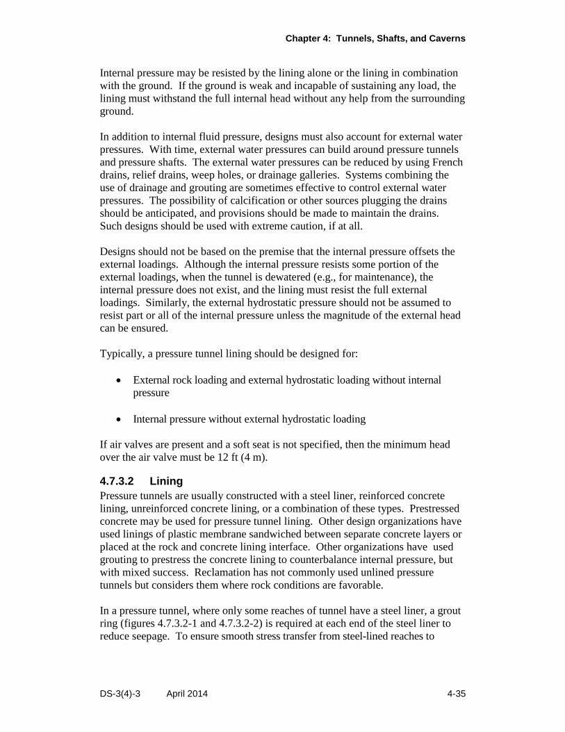
Chapter 4: Tunnels, Shafts, and Caverns
DS-3(4)-3 April 2014 4-35
Internal pressure may be resisted by the lining alone or the lining in combination
with the ground. If the ground is weak and incapable of sustaining any load, the
lining must withstand the full internal head without any help from the surrounding
ground.
In addition to internal fluid pressure, designs must also account for external water
pressures. With time, external water pressures can build around pressure tunnels
and pressure shafts. The external water pressures can be reduced by using French
drains, relief drains, weep holes, or drainage galleries. Systems combining the
use of drainage and grouting are sometimes effective to control external water
pressures. The possibility of calcification or other sources plugging the drains
should be anticipated, and provisions should be made to maintain the drains.
Such designs should be used with extreme caution, if at all.
Designs should not be based on the premise that the internal pressure offsets the
external loadings. Although the internal pressure resists some portion of the
external loadings, when the tunnel is dewatered (e.g., for maintenance), the
internal pressure does not exist, and the lining must resist the full external
loadings. Similarly, the external hydrostatic pressure should not be assumed to
resist part or all of the internal pressure unless the magnitude of the external head
can be ensured.
Typically, a pressure tunnel lining should be designed for:
External rock loading and external hydrostatic loading without internal
pressure
Internal pressure without external hydrostatic loading
If air valves are present and a soft seat is not specified, then the minimum head
over the air valve must be 12 ft (4 m).
4.7.3.2 Lining
Pressure tunnels are usually constructed with a steel liner, reinforced concrete
lining, unreinforced concrete lining, or a combination of these types. Prestressed
concrete may be used for pressure tunnel lining. Other design organizations have
used linings of plastic membrane sandwiched between separate concrete layers or
placed at the rock and concrete lining interface. Other organizations have used
grouting to prestress the concrete lining to counterbalance internal pressure, but
with mixed success. Reclamation has not commonly used unlined pressure
tunnels but considers them where rock conditions are favorable.
In a pressure tunnel, where only some reaches of tunnel have a steel liner, a grout
ring (figures 4.7.3.2-1 and 4.7.3.2-2) is required at each end of the steel liner to
reduce seepage. To ensure smooth stress transfer from steel-lined reaches to
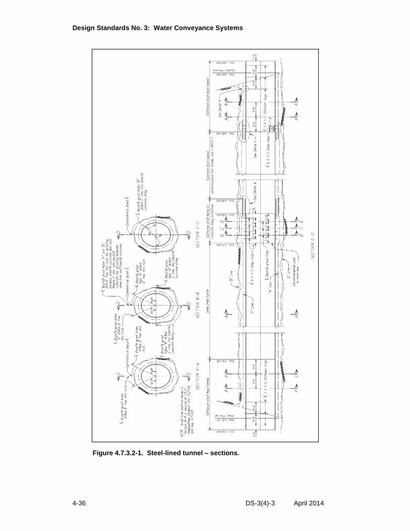
Design Standards No. 3: Water Conveyance Systems
4-36 DS-3(4)-3 April 2014
Figure 4.7.3.2-1. Steel-lined tunnel – sections.
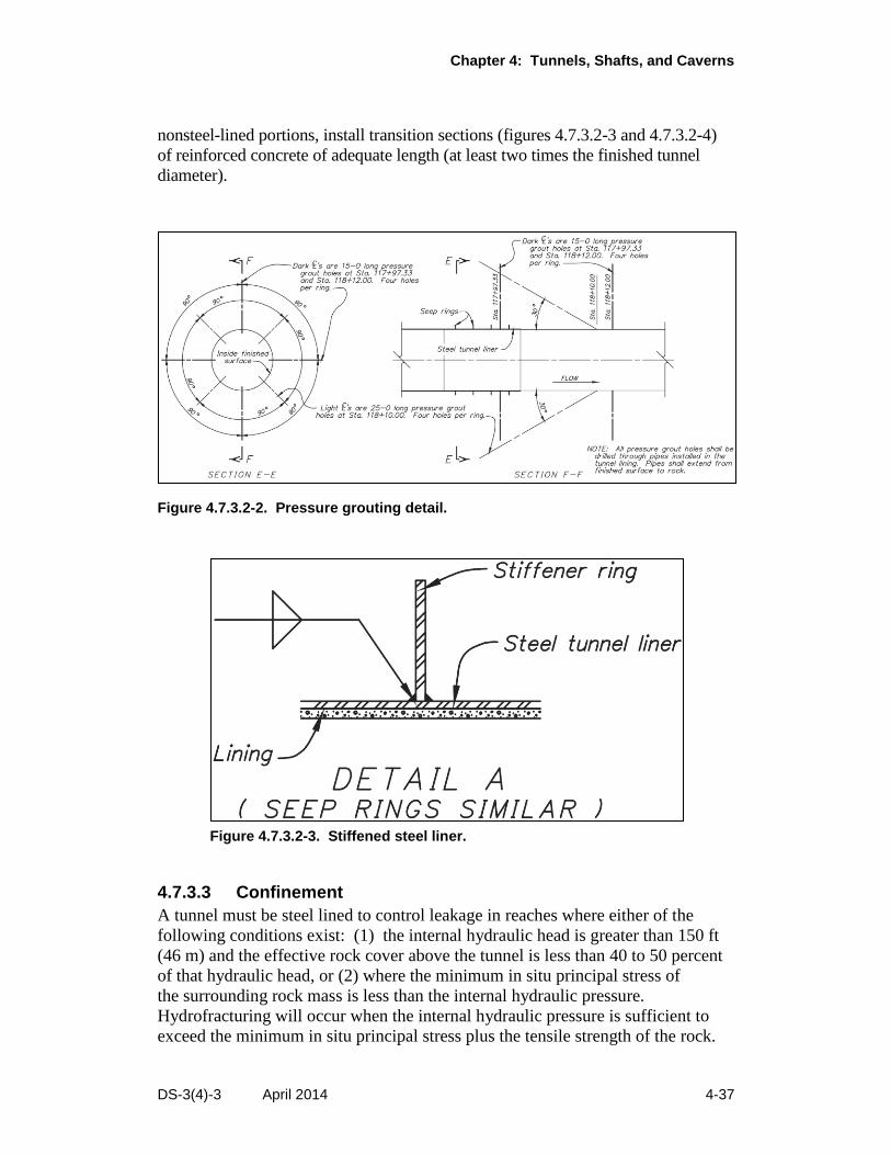
Chapter 4: Tunnels, Shafts, and Caverns
DS-3(4)-3 April 2014 4-37
nonsteel-lined portions, install transition sections (figures 4.7.3.2-3 and 4.7.3.2-4)
of reinforced concrete of adequate length (at least two times the finished tunnel
diameter).
Figure 4.7.3.2-2. Pressure grouting detail.
Figure 4.7.3.2-3. Stiffened steel liner.
4.7.3.3 Confinement
A tunnel must be steel lined to control leakage in reaches where either of the
following conditions exist: (1) the internal hydraulic head is greater than 150 ft
(46 m) and the effective rock cover above the tunnel is less than 40 to 50 percent
of that hydraulic head, or (2) where the minimum in situ principal stress of
the surrounding rock mass is less than the internal hydraulic pressure.
Hydrofracturing will occur when the internal hydraulic pressure is sufficient to
exceed the minimum in situ principal stress plus the tensile strength of the rock.
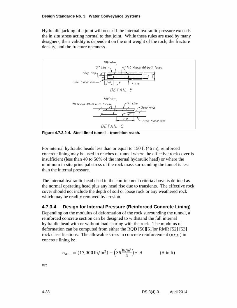
Design Standards No. 3: Water Conveyance Systems
4-38 DS-3(4)-3 April 2014
Hydraulic jacking of a joint will occur if the internal hydraulic pressure exceeds
the in situ stress acting normal to that joint. While these rules are used by many
designers, their validity is dependent on the unit weight of the rock, the fracture
density, and the fracture openness.
Figure 4.7.3.2-4. Steel-lined tunnel – transition reach.
For internal hydraulic heads less than or equal to 150 ft (46 m), reinforced
concrete lining may be used in reaches of tunnel where the effective rock cover is
insufficient (less than 40 to 50% of the internal hydraulic head) or where the
minimum in situ principal stress of the rock mass surrounding the tunnel is less
than the internal pressure.
The internal hydraulic head used in the confinement criteria above is defined as
the normal operating head plus any head rise due to transients. The effective rock
cover should not include the depth of soil or loose rock or any weathered rock
which may be readily removed by erosion.
4.7.3.4 Design for Internal Pressure (Reinforced Concrete Lining)
Depending on the modulus of deformation of the rock surrounding the tunnel, a
reinforced concrete section can be designed to withstand the full internal
hydraulic head with or without load sharing with the rock. The modulus of
deformation can be computed from either the RQD [50][51]or RMR [52] [53]
rock classifications. The allowable stress in concrete reinforcement (σALL ) in
concrete lining is:
σALL = (17,000 lb in2⁄ ) − (35lb/in2
ft) ∗ H (H in ft)
or:
Chapter 4: Tunnels, Shafts, and Caverns
DS-3(4)-3 April 2014 4-39
σALL = (117 MPa) − (0.79 MPa
m) ∗ H (H in m)
but not less than 12,000 lb/in2 (83 MPa)
where:
H = Hydraulic head (includes head rise from transients)
The maximum circumferential or longitudinal reinforcement spacing shall not be
greater than 12 inches (30.5 cm).
4.7.3.5 Design for Internal Pressure (Steel Liner)
For massive rock with very few joints, the backfill concrete and surrounding rock
can be considered to share part of the internal pressure load where the tension in
the rock at a depth of 33 ft (10 m) below the ground surface is less than the
compression stress at this location [54]. For lesser quality rock and wider joints,
there is no accepted design approach. The designer should evaluate each instance
and take a conservative approach (requiring more cover before assuming load
sharing).
Where load sharing is not assured, the steel liner is designed to resist the full load
from internal pressure without any consideration of load transfer to the backfill
concrete and surrounding rock. The allowable tensile stress of the steel is 50% of
the yield stress.
Where the backfill concrete and the surrounding rock can be considered to share
part of the internal pressure load, two conditions are checked: (1) the internal
pressure is assumed to be resisted by the steel liner alone, with an allowable
tensile stress of 75% of the yield stress of the steel and (2) the load from the
internal pressure is distributed (use load-sharing formulas) to the backfill concrete
and surrounding rock where the allowable tensile stress of the steel is of 50% of
the yield stress.
The hydraulic head used to design the steel liner is the normal operating head
plus any head rise due to transients. It is permissible to use stiffeners (see
figure 4.7.3.2-3), although this is discouraged because of construction difficulties,
or drain pipes to reduce the wall thickness of a steel liner.
The thickness for a steel liner by bursting analysis is given by the equation:
𝑡𝑆𝐿 =𝑃𝑖𝑅𝑆
𝜎
Design Standards No. 3: Water Conveyance Systems
4-40 DS-3(4)-3 April 2014
where:
tSL = Thickness of steel liner
Pi = Internal pressure
Rs = Radius of steel liner
σ = Allowable stress
For a liner with a diameter less than or equal to 6.6 ft (2.0 m), the minimum
thickness for handling (tmin) is given by the equation:
𝑡𝑚𝑖𝑛 =𝐷 + 20
400
where:
tmin = Minimum thickness in inches
D = Diameter in inches
or:
𝑡𝑚𝑖𝑛 =𝐷 + 508
400
where: tmin = Minimum thickness in mm D = Diameter in mm When the diameter of the liner is greater than 6.6 ft (2.0 m), use the appropriate curve [55] for the specified strength of steel to select the minimum thickness for handling. When a steel liner is encased in backfill concrete, an annular gap (figure 4.7.3.5-1) may form near the interface of the steel liner and backfill concrete. The gap is caused by a combination of drying shrinkage of the concrete and the difference between the maximum temperature of the concrete reached during curing and the lowest temperature of the conveyed water during operation. The formation of an annular gap is dependent on the temperature variation and is given by equation:
∆𝐺= 𝛼 ∗ ∆𝑇 ∗ 𝑅𝑆 where: ΔG = Gap thickness α = Coefficient of thermal expansion of steel ΔT = Range of temperature variation RS = Outside radius of steel liner
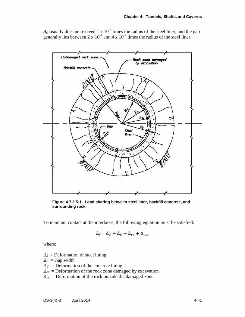
Chapter 4: Tunnels, Shafts, and Caverns
DS-3(4)-3 April 2014 4-41
ΔG usually does not exceed 1 x 10⁻³
times the radius of the steel liner, and the gap generally lies between 2 x 10
-4 and 4 x 10
-4 times the radius of the steel liner.
Figure 4.7.3.5-1. Load sharing between steel liner, backfill concrete, and surrounding rock.
To maintain contact at the interfaces, the following equation must be satisfied:
∆𝑆= ∆𝐺 + ∆𝐶 + ∆𝑐𝑟 + ∆𝑢𝑐𝑟 where: ΔS = Deformation of steel lining ΔG = Gap width ΔC = Deformation of the concrete lining Δcr = Deformation of the rock zone damaged by excavation Δucr = Deformation of the rock outside the damaged zone
Design Standards No. 3: Water Conveyance Systems
4-42 DS-3(4)-3 April 2014
Considering steel liner to act as a thin cylinder, but the concrete lining and rock to
act as thick cylinders of elastic media and plane strain conditions, the pressure
taken by steel liner, PS is given by the formula [42]:
{𝛼 ∗ ∆𝑇 ∗ 𝑅𝑆 + 0.5 ∗ 𝑃𝑖 ∗ [(1 − 𝑣𝐶
2
𝐸𝑐) ∗
1
𝑅𝐶∗ (𝑅𝐶
2 − 𝑅𝐺2) +
𝑅𝐺
𝑅𝑢𝑐𝑟 ∗ 𝑅𝑐∗
(1 − 𝑣𝑐𝑟2 )
𝐸𝑐𝑟∗ (𝑅𝑢𝑐𝑟
2 − 𝑅𝐶2) + 2 ∗ (
1 + 𝑣𝑢𝑐𝑟
𝐸𝑢𝑐𝑟) ∗ 𝑅𝐺]}
PS = _________________________________________________________________________________
{𝑅𝑆2 ∗
(1 − 𝑣𝑠2)
𝑡𝑆𝐿 ∗ 𝐸𝑠+ 0.5 ∗ [
(1 − 𝑣𝑐2)
𝐸𝑐∗
1
𝑅𝐶∗ (𝑅𝐶
2 − 𝑅𝐺2) +
(RG
Rucr ∗ RC) ∗ (
1 − 𝑣cr2
Ecr) ∗ (Rucr
2 − RC2) + 2 ∗ (
1 + 𝑣ucr
Eucr) ∗ RG]}
where the new terms are:
Ec = Modulus of elasticity of concrete
Es = Modulus of elasticity of steel
Ecr = Modulus of deformation of the rock damaged by excavation
Eucr = Modulus of deformation of the rock outside of the damaged zone
vc = Poisson’s ratio of concrete
vs = Poisson’s ratio of steel
vcr = Poisson’s ratio of the rock damaged by excavation
vucr = Poisson’s ratio of the rock outside the damaged zone
RD = Radius to the inside of the steel liner
RS = Radius to the outside (gap side) of the steel liner
RG = Radius to the outside of gap
RC = Radius to the contact between the backfill concrete and the rock
Rucr = Radius to the rock undamaged by excavation
tSL = Thickness of steel lining
ΔT = Change in temperature between constructed and operating conditions
α = Coefficient of thermal expansion
Pi = Internal hydrostatic pressure plus pressure rise due to hydraulic transients
Ps = Pressure taken by steel liner
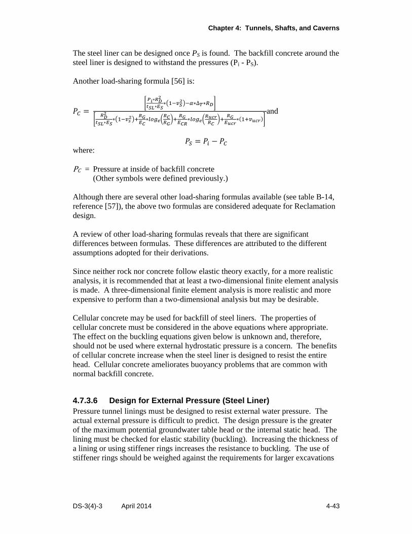
Chapter 4: Tunnels, Shafts, and Caverns
DS-3(4)-3 April 2014 4-43
The steel liner can be designed once PS is found. The backfill concrete around the
steel liner is designed to withstand the pressures (Pi - PS).
Another load-sharing formula [56] is:
𝑃𝐶 = [𝑃𝑖∗𝑅𝐷
2
𝑡𝑆𝐿∗𝐸𝑆∗(1−𝑣𝑆
2)−𝛼∗∆𝑇∗𝑅𝐷]
[𝑅𝐷
2
𝑡𝑆𝐿∗𝐸𝑆∗(1−𝑣𝑠
2)+𝑅𝐺𝐸𝐶
∗𝑙𝑜𝑔𝑒(𝑅𝐶𝑅𝐺
)+𝑅𝐺𝐸𝐶𝑅
∗𝑙𝑜𝑔𝑒(𝑅𝑢𝑐𝑟𝑅𝐶
)+𝑅𝐺
𝐸𝑢𝑐𝑟∗(1+𝑣𝑢𝑐𝑟)]
and
𝑃𝑆 = 𝑃𝑖 − 𝑃𝐶 where:
PC = Pressure at inside of backfill concrete
(Other symbols were defined previously.)
Although there are several other load-sharing formulas available (see table B-14,
reference [57]), the above two formulas are considered adequate for Reclamation
design.
A review of other load-sharing formulas reveals that there are significant
differences between formulas. These differences are attributed to the different
assumptions adopted for their derivations.
Since neither rock nor concrete follow elastic theory exactly, for a more realistic
analysis, it is recommended that at least a two-dimensional finite element analysis
is made. A three-dimensional finite element analysis is more realistic and more
expensive to perform than a two-dimensional analysis but may be desirable.
Cellular concrete may be used for backfill of steel liners. The properties of
cellular concrete must be considered in the above equations where appropriate.
The effect on the buckling equations given below is unknown and, therefore,
should not be used where external hydrostatic pressure is a concern. The benefits
of cellular concrete increase when the steel liner is designed to resist the entire
head. Cellular concrete ameliorates buoyancy problems that are common with
normal backfill concrete.
4.7.3.6 Design for External Pressure (Steel Liner)
Pressure tunnel linings must be designed to resist external water pressure. The
actual external pressure is difficult to predict. The design pressure is the greater
of the maximum potential groundwater table head or the internal static head. The
lining must be checked for elastic stability (buckling). Increasing the thickness of
a lining or using stiffener rings increases the resistance to buckling. The use of
stiffener rings should be weighed against the requirements for larger excavations
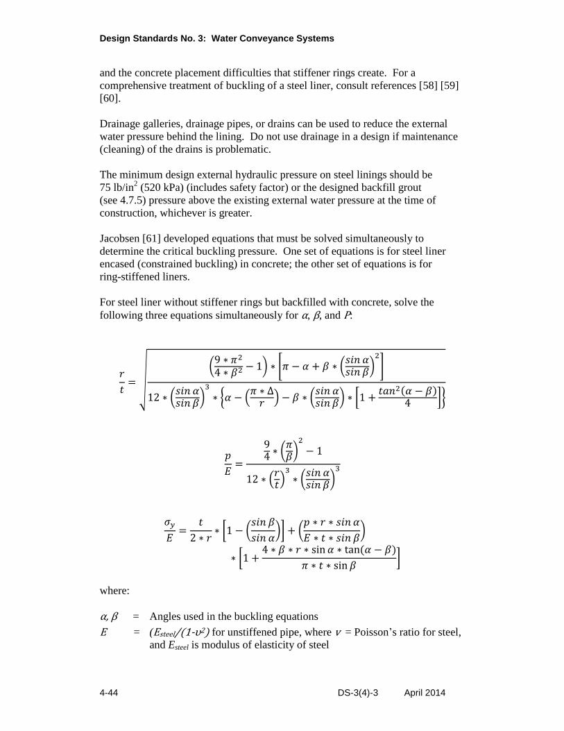
Design Standards No. 3: Water Conveyance Systems
4-44 DS-3(4)-3 April 2014
and the concrete placement difficulties that stiffener rings create. For a
comprehensive treatment of buckling of a steel liner, consult references [58] [59]
[60].
Drainage galleries, drainage pipes, or drains can be used to reduce the external
water pressure behind the lining. Do not use drainage in a design if maintenance
(cleaning) of the drains is problematic.
The minimum design external hydraulic pressure on steel linings should be
75 lb/in2 (520 kPa) (includes safety factor) or the designed backfill grout
(see 4.7.5) pressure above the existing external water pressure at the time of
construction, whichever is greater.
Jacobsen [61] developed equations that must be solved simultaneously to
determine the critical buckling pressure. One set of equations is for steel liner
encased (constrained buckling) in concrete; the other set of equations is for
ring-stiffened liners.
For steel liner without stiffener rings but backfilled with concrete, solve the
following three equations simultaneously for α, β, and P:
𝑟
𝑡= √
(9 ∗ 𝜋2
4 ∗ 𝛽2 − 1) ∗ [𝜋 − 𝛼 + 𝛽 ∗ (𝑠𝑖𝑛 𝛼𝑠𝑖𝑛 𝛽
)2
]
12 ∗ (𝑠𝑖𝑛 𝛼𝑠𝑖𝑛 𝛽
)3
∗ {𝛼 − (𝜋 ∗ ∆
𝑟 ) − 𝛽 ∗ (𝑠𝑖𝑛 𝛼𝑠𝑖𝑛 𝛽
) ∗ [1 +𝑡𝑎𝑛2(𝛼 − 𝛽)
4 ]}
𝑝
𝐸=
94 ∗ (
𝜋𝛽)2
− 1
12 ∗ (𝑟𝑡)
3
∗ (𝑠𝑖𝑛 𝛼𝑠𝑖𝑛 𝛽
)3
𝜎𝑦
𝐸=
𝑡
2 ∗ 𝑟∗ [1 − (
𝑠𝑖𝑛 𝛽
𝑠𝑖𝑛 𝛼)] + (
𝑝 ∗ 𝑟 ∗ 𝑠𝑖𝑛 𝛼
𝐸 ∗ 𝑡 ∗ 𝑠𝑖𝑛 𝛽)
∗ [1 +4 ∗ 𝛽 ∗ 𝑟 ∗ sin 𝛼 ∗ tan(𝛼 − 𝛽)
𝜋 ∗ 𝑡 ∗ sin 𝛽]
where:
α, β = Angles used in the buckling equations
E = (Esteel/(1-υ2) for unstiffened pipe, where v = Poisson’s ratio for steel,
and Esteel is modulus of elasticity of steel
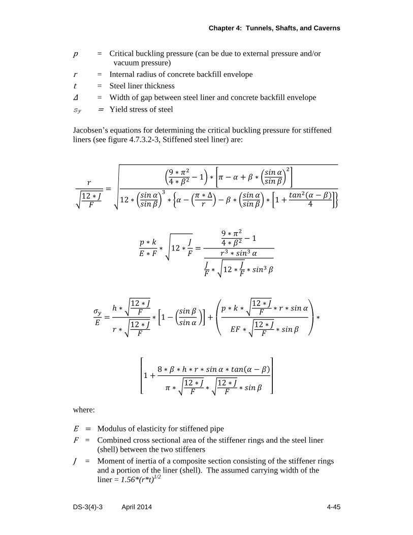
Chapter 4: Tunnels, Shafts, and Caverns
DS-3(4)-3 April 2014 4-45
p = Critical buckling pressure (can be due to external pressure and/or
vacuum pressure)
r = Internal radius of concrete backfill envelope
t = Steel liner thickness
Δ = Width of gap between steel liner and concrete backfill envelope
sy = Yield stress of steel
Jacobsen’s equations for determining the critical buckling pressure for stiffened
liners (see figure 4.7.3.2-3, Stiffened steel liner) are:
𝑟
√12 ∗ 𝐽𝐹
= √
(9 ∗ 𝜋2
4 ∗ 𝛽2 − 1) ∗ [𝜋 − 𝛼 + 𝛽 ∗ (𝑠𝑖𝑛 𝛼𝑠𝑖𝑛 𝛽
)2
]
12 ∗ (𝑠𝑖𝑛 𝛼𝑠𝑖𝑛 𝛽
)3
∗ {𝛼 − (𝜋 ∗ ∆
𝑟 ) − 𝛽 ∗ (𝑠𝑖𝑛 𝛼𝑠𝑖𝑛 𝛽
) ∗ [1 +𝑡𝑎𝑛2(𝛼 − 𝛽)
4 ]}
𝑝 ∗ 𝑘
𝐸 ∗ 𝐹∗ √12 ∗
𝐽
𝐹=
9 ∗ 𝜋2
4 ∗ 𝛽2 − 1
𝑟3 ∗ 𝑠𝑖𝑛3 𝛼
𝐽𝐹 ∗ √12 ∗
𝐽𝐹 ∗ 𝑠𝑖𝑛3 𝛽
𝜎𝑦
𝐸=
ℎ ∗ √12 ∗ 𝐽𝐹
𝑟 ∗ √12 ∗ 𝐽𝐹
∗ [1 − (𝑠𝑖𝑛 𝛽
𝑠𝑖𝑛 𝛼 )] +
(
𝑝 ∗ 𝑘 ∗ √12 ∗ 𝐽
𝐹 ∗ 𝑟 ∗ 𝑠𝑖𝑛 𝛼
𝐸𝐹 ∗ √12 ∗ 𝐽𝐹 ∗ 𝑠𝑖𝑛 𝛽 )
∗
[
1 +8 ∗ 𝛽 ∗ ℎ ∗ 𝑟 ∗ 𝑠𝑖𝑛 𝛼 ∗ 𝑡𝑎𝑛(𝛼 − 𝛽)
𝜋 ∗ √12 ∗ 𝐽𝐹 ∗ √12 ∗ 𝐽
𝐹 ∗ 𝑠𝑖𝑛 𝛽 ]
where:
E = Modulus of elasticity for stiffened pipe
F = Combined cross sectional area of the stiffener rings and the steel liner
(shell) between the two stiffeners
J = Moment of inertia of a composite section consisting of the stiffener rings
and a portion of the liner (shell). The assumed carrying width of the
liner = 1.56*(r*t)1/2
Design Standards No. 3: Water Conveyance Systems
4-46 DS-3(4)-3 April 2014
h = Distance to the outer fiber of the stiffener ring from the neutral axis of the
composite section
k = Distance between stiffener rings
4.7.4 Water Control
4.7.4.1 General Concepts
Water may infiltrate or exfiltrate a tunnel during or after construction. Inflowing
water can carry finer materials into the tunnel, resulting in voids behind the lining
and the potential for lining instability. Infiltrating waters can also carry dissolved
gases, such as hydrogen sulfide, which can potentially create a toxic work
environment. Acidic waters can corrode a lining.
Infiltrating water will lower the water table and may result in increased settlement
beneath surface structures about the tunnel. Wells influenced by the groundwater
drawdown will incur higher pumping costs. Infiltrating water may also carry
heavy metals and other deleterious substances that can contaminate the quality of
the tunnel water. Infiltrating clean water at small flow rates is usually acceptable.
Exfiltrating water effects, particularly for a pressure tunnel, should be evaluated.
Such flows can result in hydraulic jacking or slope stability failures at locations of
low cover. Exfiltration may result in contractual water deliveries not being met if
conveyance system losses have not been adequately predicted.
There are two philosophical methods of water control: exclusion and extraction.
Exclusion methods prevent water entry and exit by building some kind of
impermeable barrier, such as a steel liner. Barriers can also be formed by
pressure grouting the rock surrounding the tunnel, filling joints with caulking
compounds, water stops, or by installing plastic sheets having thermoplastic
splices.
Extraction methods that drain water away during construction may include
pumping, well-point ejectors, sump pumps, and panning. Drainage following
construction is by weep holes.
The principal geologist estimates the rate of infiltration to establish a water
control unit bid cost during construction. Detailed analysis is required when
water inflow is critical to the design.
4.7.4.2 Drainage
While small circular tunnels may be economically designed to withstand
considerable external water pressure without drainage relief, the design of
concrete linings of larger tunnels, especially noncircular shaped tunnels, should
consider the use of weep holes or drainage holes to reduce external hydrostatic
pressure on the concrete lining. Weep holes are not appropriate where: (1) a
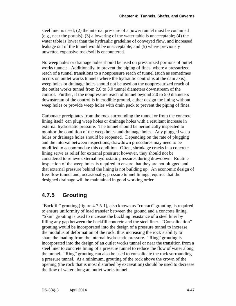
Chapter 4: Tunnels, Shafts, and Caverns
DS-3(4)-3 April 2014 4-47
steel liner is used; (2) the internal pressure of a power tunnel must be contained
(e.g., near the portals); (3) a lowering of the water table is unacceptable; (4) the
water table is lower than the hydraulic gradeline of conveyed flow, and increased
leakage out of the tunnel would be unacceptable; and (5) where previously
unwetted expansive rock/soil is encountered.
No weep holes or drainage holes should be used on pressurized portions of outlet
works tunnels. Additionally, to prevent the piping of fines, where a pressurized
reach of a tunnel transitions to a nonpressure reach of tunnel (such as sometimes
occurs on outlet works tunnels where the hydraulic control is at the dam axis),
weep holes or drainage holes should not be used on the nonpressurized reach of
the outlet works tunnel from 2.0 to 5.0 tunnel diameters downstream of the
control. Further, if the nonpressure reach of tunnel beyond 2.0 to 5.0 diameters
downstream of the control is in erodible ground, either design the lining without
weep holes or provide weep holes with drain pack to prevent the piping of fines.
Carbonate precipitates from the rock surrounding the tunnel or from the concrete
lining itself can plug weep holes or drainage holes with a resultant increase in
external hydrostatic pressure. The tunnel should be periodically inspected to
monitor the condition of the weep holes and drainage holes. Any plugged weep
holes or drainage holes should be reopened. Depending on the rate of plugging
and the interval between inspections, drawdown procedures may need to be
modified to accommodate this condition. Often, shrinkage cracks in a concrete
lining serve as relief for external pressure; however, they should not be
considered to relieve external hydrostatic pressures during drawdown. Routine
inspection of the weep holes is required to ensure that they are not plugged and
that external pressure behind the lining is not building up. An economic design of
free-flow tunnel and, occasionally, pressure tunnel linings requires that the
designed drainage will be maintained in good working order.
4.7.5 Grouting
“Backfill” grouting (figure 4.7.5-1), also known as “contact” grouting, is required
to ensure uniformity of load transfer between the ground and a concrete lining.
“Skin” grouting is used to increase the buckling resistance of a steel liner by
filling any gap between the backfill concrete and the steel liner. “Consolidation”
grouting would be incorporated into the design of a pressure tunnel to increase
the modulus of deformation of the rock, thus increasing the rock’s ability to
share the loading from the internal hydrostatic pressure. “Ring” grouting is
incorporated into the design of an outlet works tunnel or near the transition from a
steel liner to concrete lining of a pressure tunnel to reduce the flow of water along
the tunnel. “Ring” grouting can also be used to consolidate the rock surrounding
a pressure tunnel. At a minimum, grouting of the rock above the crown of the
opening (the rock that is most disturbed by excavation) should be used to decrease
the flow of water along an outlet works tunnel.
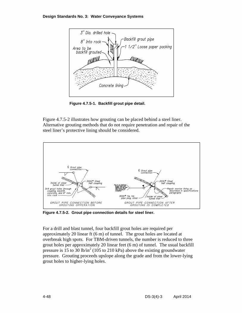
Design Standards No. 3: Water Conveyance Systems
4-48 DS-3(4)-3 April 2014
Figure 4.7.5-1. Backfill grout pipe detail.
Figure 4.7.5-2 illustrates how grouting can be placed behind a steel liner.
Alternative grouting methods that do not require penetration and repair of the
steel liner’s protective lining should be considered.
Figure 4.7.5-2. Grout pipe connection details for steel liner.
For a drill and blast tunnel, four backfill grout holes are required per
approximately 20 linear ft (6 m) of tunnel. The grout holes are located at
overbreak high spots. For TBM-driven tunnels, the number is reduced to three
grout holes per approximately 20 linear feet (6 m) of tunnel. The usual backfill
pressure is 15 to 30 lb/in2 (105 to 210 kPa) above the existing groundwater
pressure. Grouting proceeds upslope along the grade and from the lower-lying
grout holes to higher-lying holes.
Chapter 4: Tunnels, Shafts, and Caverns
DS-3(4)-3 April 2014 4-49
4.7.6 Bifurcation and Manifold
Consult mechanical engineers who are experienced in designing bifurcations and
manifolds.
4.7.7 Special Features
4.7.7.1 Staging Area
The staging areas must provide sufficient work space for the contractor and the
Government. The staging area’s size and shape depend on the selected method
of construction, the contractor’s space requirements, and the terrain. Terrain
constraints such as steep grades, proximity to steep slopes, or narrow valleys tend
to require an elongated staging area.
Normally, a 500-ft by 300-ft (150-m by 90-m) area adequately serves as a staging
area. An additional 150-ft by 100-ft (45-m by 30-m) area is required for treating
water recovered during tunneling before it enters the natural drainage.
The staging area must be accessible; otherwise, an access road is required. If
required, the Government must obtain right-of-way for the staging area and other
facilities before the start of actual construction.
4.7.7.2 Station Markers
Permanent station markers should be installed in tunnels to facilitate maintenance
and inspections. Station marker spacing should not exceed 1,000 ft or 500 m.
Closer spacing of either 200 ft or 100 m may be warranted to ensure that workers
are always within a standard survey tape length (100 ft or 50 m) of a station
marker.
4.7.7.3 Instrumentation
The instrumentation plans, objectives, and justifications should be prepared by a
knowledgeable design engineer and coordinated with appropriate field personnel,
the cost estimator, specification writer, construction management personnel, and
the personnel responsible for instrumentation. Extensometers are used to monitor
deformations of underground openings or tunnel linings. Such convergence
measurements are typically required for outlet works tunnels and should be
considered for water conveyance tunnels where squeezing or swelling ground is
anticipated or encountered.
4.7.8 Construction Schedules
Construction schedules shall be made whenever an accurate construction duration
is required. The critical path shall be found. All expected submittals, holidays,
Design Standards No. 3: Water Conveyance Systems
4-50 DS-3(4)-3 April 2014
and seasons of the year shall be taken into account. For excavating and lining, the
schedule should be based on 24 hours a days, 7 days a week. This allows for
maintenance and surveying during the weekends.
Based on working days, the estimated average daily advance for hard rock
tunneling should not be greater than:
2.1 times the “B” line width for drill and blast excavation of supported
tunnels less than 18 ft (5.5 m) in width; the lessor of 1.2 times the “B” line
width, and 26 ft (8 m) for drill and blast excavation of supported tunnels
between 18 ft (5.5 m) and 23 ft (7 m) in width.
154 ft (47 m) for TBM excavating. The penetration rate is dependent on the
strength of the rock, the amount of fracturing, the angle of the bedding, the
tensile versus compressive properties of the rock, and the machine design.
The advance rate is a function of the penetration rate, the time to reset the
machine, the time to erect a ring of segments, and the percent of time the
TBM is used.
35 ft (11 m) per day for roadheader excavation of supported tunnels. The
cutting rate is dependent on the compressive strength of the rock joint
spacing, anistrophy, clay content, and machine design. The advance rate is
a function of the cutting rate, the cross sectional area being excavated, and
the percent of time the roadheader is being used.
Based on working days, the average daily advance used for shaft excavating
should be no greater than:
14.8 ft (4.5 m) for drill and blast. The advance rate is dependent on the
diameter and depth of the shaft.
65 ft (20 m) for raise bore. The advance rate is dependent on rock strength
and highly dependent on mucking rates. The drilling of the pilot hole
precedes the reaming, and its average daily advance should be no greater
than 225 ft (69 m) for this operation.
Based on working days, the estimated average daily advance for soft ground
tunneling should not be greater than:
75 ft (23 m) for TBM excavating.
Allow 10 to 11 months to manufacture a 20-ft (6-m) diameter or smaller TBM
and 13 months to 15 months to manufacture a 39-ft to 49-ft (12-m to 15-m)
diameter TBM. Delivery time is an additional 4 to 5 weeks. Onsite assembly
requires 2 to 3 months.
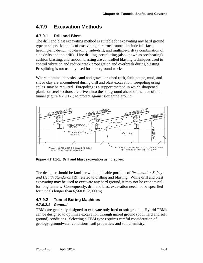
Chapter 4: Tunnels, Shafts, and Caverns
DS-3(4)-3 April 2014 4-51
4.7.9 Excavation Methods
4.7.9.1 Drill and Blast
The drill and blast excavating method is suitable for excavating any hard ground
type or shape. Methods of excavating hard rock tunnels include full-face,
heading-and-bench, top-heading, side-drift, and multiple-drift (a combination of
side drifts and top drift). Line drilling, presplitting (also known as preshearing),
cushion blasting, and smooth blasting are controlled blasting techniques used to
control vibration and reduce crack propagation and overbreak during blasting.
Presplitting is not usually used for underground works.
Where morainal deposits, sand and gravel, crushed rock, fault gouge, mud, and
silt or clay are encountered during drill and blast excavation, forepoling using
spiles may be required. Forepoling is a support method in which sharpened
planks or steel sections are driven into the soft ground ahead of the face of the
tunnel (figure 4.7.9.1-1) to protect against sloughing ground.
Figure 4.7.9.1-1. Drill and blast excavation using spiles.
The designer should be familiar with applicable portions of Reclamation Safety
and Health Standards [19] related to drilling and blasting. While drill and blast
excavating may be used to excavate any hard ground, it may not be economical
for long tunnels. Consequently, drill and blast excavation need not be specified
for tunnels longer than 6,560 ft (2,000 m).
4.7.9.2 Tunnel Boring Machines
4.7.9.2.1 General
TBMs are generally designed to excavate only hard or soft ground. Hybrid TBMs
can be designed to optimize excavation through mixed ground (both hard and soft
ground) conditions. Selecting a TBM type requires careful consideration of
geology, groundwater conditions, soil properties, and soil chemistry.
Design Standards No. 3: Water Conveyance Systems
4-52 DS-3(4)-3 April 2014
Reclamation specifications that allow the use of TBMs should include
contingency plans to complete the excavation if the selected TBM fails to advance
the tunnel face in a manner or at a rate acceptable to Reclamation.
4.7.9.2.2 Hard Rock
The three types of hard rock tunnel boring machines are the main-beam,
single-shield and the double-shield. The main-beam TBM does not have a shield,
and its use is advantageous where the rock is stable with minimal underground
water. In reaches of tunnel where the rock is not competent to stand unsupported,
the design of a main-beam TBM can be modified to provide continuous support
concurrent with its mining (excavation) cycle. Either a single-shield or double-
shield TBM can be used in ground requiring the safety of a shield to erect a
segmental lining. The advantages of using a single shield TBM (compared to a
double-shield TBM) are: (1) its short shield length minimizes the shield’s surface
exposure to squeezing or swelling ground forces that could entrap the shield,
and (2) the short shield length enables the TBM to turn a smaller radius. The
disadvantage of using a single-shield TBM is that the mining cycle must be
suspended while a segmental lining is erected within the shield. The advantage of
using the longer double-shield TBM is that the mining cycle is concurrent with
the erection of a ring of precast concrete segments within the tail shield, which
enables a larger advance rate (progress rate).
The size of hard rock TBMs ranges from about 6 ft to about 47.2 ft (2 m to
14.4 m) in diameter. The average progress rate can range anywhere from 17.4 ft
to 154 ft per working day (5 m to 47 m per day) with maximum daily progress
rates of 98 ft to 565.5 ft (30 m to 172.4 m) [62].
The advantages of TBMs include high daily footage of excavation, minimum
damage to the rock surrounding the tunnel, minimum volume of overbreak, and,
therefore, minimum amount of concrete lining. A disadvantage of TBMs is
that they require a long lead time for machine delivery (see Section 4.7.8,
“Construction Schedules”).
Generally, a new TBM requires at least a 10,000-ft (3,000-m) tunnel to be
economically competitive with the drill and blast method. However, an
increasing supply of used but proven machines of adaptable size may be available
for shorter length tunnels and be competitive with the drill and blast method.
Designers should consider designing for a TBM option when the tunnel length is
longer than 3,280 ft (1000 m.
TBMs, in general, should have the following requirements specified:
Be capable of drilling probe holes to determine water and rock conditions
ahead of the tunnel face
Be capable of drilling holes for ground consolidation
Chapter 4: Tunnels, Shafts, and Caverns
DS-3(4)-3 April 2014 4-53
Have methane and other gas detectors
Shut down automatically if the lower explosive limit for methane or other
flammable gases or vapors is detected
Have explosion-proof components as required
Have an automatic fire suppression system
Be capable of successful operation (including muck handling) in water
(inflow or construction water)
Main-beam TBMs should have the capability of roof drills and ring beam erectors
to install support if needed.
4.7.9.2.3 Soft Ground
Slurry shields and earth pressure balance (EPB) shields are used for soft ground
tunneling. The tunnel face is stabilized, and settlement of the ground surface
above the tunnel is minimized, by maintaining a steady positive pressure on the
face. Disc cutters can be added if hard ground is anticipated. The EPB method is
usually considered more efficient in cohesive soils. A slurry shield can typically
be used up to 7 bars of hydrostatic pressure, while an EPB can be used up to
3.5 bars. A fully shielded TBM has been designed for 17 bars (247 lb/in2) of
hydrostatic pressure. A 57.5-ft (17.5-m) diameter earth pressure balance TBM is
the largest built to date.
4.7.9.3 Roadheaders
Roadheaders are boom-type (arm-type) mechanical excavators. Machine weight
currently ranges from approximately 7 tons (6 tonnes) to 149 tons (135 tonnes).
Heavier roadheaders are required to excavate harder rock. Water-jet assisted
roadheaders can also be used for harder rocks. Roadheaders have excavated rock
with compressive strengths of 22,000 lb/in2 (150 MPa); however, they are
generally most effective excavating rock that is less than 5,000 lb/in2 (30 MPa).
The practicality of using a roadheader for tunnel excavation is dependent not
only on the compressive strength of the rock, but also on the joint spacing,
anistrophy, clay content, and quartz content, as well as the size (weight) of
roadheader that will fit within the tunnel.
Roadheaders are economical for tunnel lengths similar to those of drill and blast
excavating (see Section 4.7.9.1, “Drill and Blast”).
4.7.9.4 Compressed Air
Reclamation has never used the compressed-air method of excavation; thus, no
Reclamation standards exist.
Design Standards No. 3: Water Conveyance Systems
4-54 DS-3(4)-3 April 2014
4.7.9.5 Tunnel Jacking
The tunnel jacking process consists of pushing one pipe or pipe-like section of
tunnel after another by hydraulically operated jacks while excavation is taking
place at the tunnel face within a shield. Open face excavation can be done
manually, with an excavator (back-actor) or a cutter boom. Excavation that
requires a closed face can be accomplished using a compressed air shield. In
addition, closed face excavation of pipes can be accomplished by using a
microtunnel boring machine (MTBM). The two basic types of microtunnel
boring machines are the slurry type and the auger type. A reaction frame or thrust
block with proper anchorage is constructed before the start of tunnel jacking to
provide necessary reaction for hydraulically operated jacks.
Where tunnel jacking is specified, an alternative method, such as shield tunneling
with liner plate, should be included in the specifications.
4.7.9.6 Other Methods of Tunnel Construction
Soft ground (earth) tunnels can be excavated using an open shield or be hand
mined using unitary excavation with steel liner plate. The cut-and-cover method
is sometimes used to construct transportation tunnels in urban settings.
Tunneling under reservoirs, rivers, or large canals is hazardous work. Such
projects should be approached with caution. Canal reaches should be drained if
practical.
4.7.9.7 Shaft Excavation
A shaft can be excavated in rock by the following methods:
Drill and blast sinking
Raise boring (drilling a pilot hole down followed by reaming up)
Raise boring plus slashing
Down boring ( drilling a pilot hole up followed by reaming down)
Blind boring
Shaft boring machines (SBM) or V-mole.
A crane with a clamshell bucket is typically used to excavate shafts in soil. The
economical minimum “A” line diameter for drill and blast excavation is 15 ft
(4.6 m). The current largest diameter by raise boring is 23.3 ft (7.1 m). V-moles
have been used to bore shafts up to 27.9 ft (8.5 m) in diameter.
Chapter 4: Tunnels, Shafts, and Caverns
DS-3(4)-3 April 2014 4-55
4.7.9.8 Cavern Excavation
Access tunnels or shafts to a cavern, such as for an underground powerhouse or a
gate chamber, must be excavated first. The cavern is then excavated using drill
and blast methods, roadheaders, or other mechanical excavators. Usually, the
cavern is excavated and supported in sections until the full excavation is
completed.
Completed caverns that are occupied full time should have at least two accesses.
4.7.9.9 Lake Taps
Large lake taps can be accomplished by the American lake tap method [63]. The
American lake tap method (figure 4.7.9.9-1) involves the following steps:
1. Excavation of the tunnel (running tunnel) only to a safe distance from the
lake
2. Excavation of an underwater bench
3. Excavation of the shaft
4. Lowering a steel liner into the shaft
5. Filling the annulus between the shaft and rock with mortar
6. Placing low-strength concrete into the debris chamber using a tremie
7. Placing a bulkhead, with piping through it, on top of the shaft
8. Dewatering the shaft through the piping
9. Excavation of the remaining length of tunnel (connecting tunnel) into the
tremie concrete
10. Lining the tunnel and debris chamber as required
11. Filling the tunnel and shaft through the piping
12. Removing the bulkhead
13. Installing the intake structure on the top of the shaft
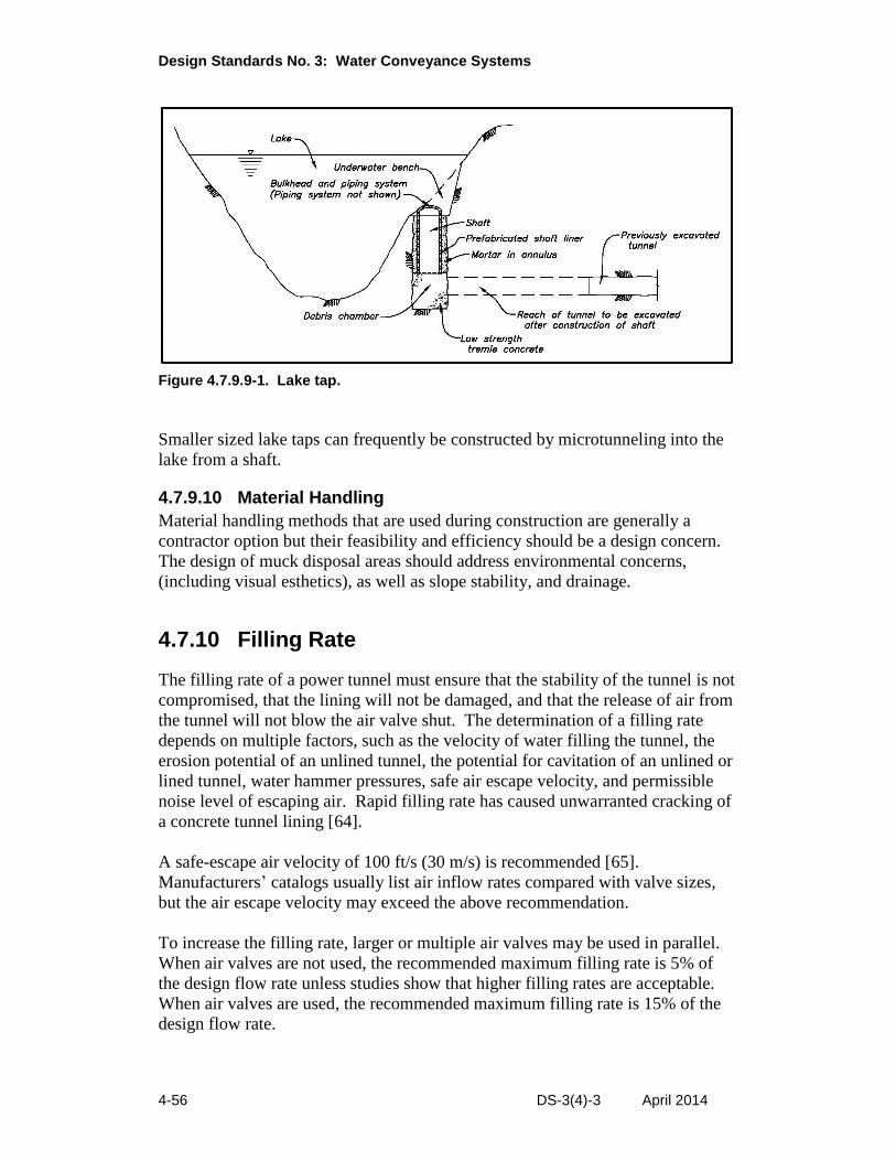
Design Standards No. 3: Water Conveyance Systems
4-56 DS-3(4)-3 April 2014
Smaller sized lake taps can frequently be constructed by microtunneling into the
lake from a shaft.
Figure 4.7.9.9-1. Lake tap.
4.7.9.10 Material Handling
Material handling methods that are used during construction are generally a
contractor option but their feasibility and efficiency should be a design concern.
The design of muck disposal areas should address environmental concerns,
(including visual esthetics), as well as slope stability, and drainage.
4.7.10 Filling Rate
The filling rate of a power tunnel must ensure that the stability of the tunnel is not
compromised, that the lining will not be damaged, and that the release of air from
the tunnel will not blow the air valve shut. The determination of a filling rate
depends on multiple factors, such as the velocity of water filling the tunnel, the
erosion potential of an unlined tunnel, the potential for cavitation of an unlined or
lined tunnel, water hammer pressures, safe air escape velocity, and permissible
noise level of escaping air. Rapid filling rate has caused unwarranted cracking of
a concrete tunnel lining [64].
A safe-escape air velocity of 100 ft/s (30 m/s) is recommended [65].
Manufacturers’ catalogs usually list air inflow rates compared with valve sizes,
but the air escape velocity may exceed the above recommendation.
To increase the filling rate, larger or multiple air valves may be used in parallel.
When air valves are not used, the recommended maximum filling rate is 5% of
the design flow rate unless studies show that higher filling rates are acceptable.
When air valves are used, the recommended maximum filling rate is 15% of the
design flow rate.
Chapter 4: Tunnels, Shafts, and Caverns
DS-3(4)-3 April 2014 4-57
4.7.11 Draining Rate
A pressure tunnel should be drained at a rate that does not allow the vacuum
pressure to fall below 7 lb/in2 absolute. When weep holes have been incorporated
into the design of a pressure tunnel, the location of the phreatic surface above the
tunnel and if maintenance of the weep holes has been performed should be
considered when determining the drainage rate. If the weep holes have become
plugged, rapid draining may subject the lining to more external head than it was
designed for.

Chapter 4: Tunnels, Shafts, and Caverns
DS-3(4)-3 April 2014 4-59
4.8 References
[1] United States National Committee on Tunneling Technology,
Subcommittee on Geotechnical Site Investigation, Geotechnical Site
Investigations for Underground Projects, Vol. I, National Academy of
Sciences, 1984.
[2] Essex, Randall J., Committee Chairman, Technical Committee on
Geotechnical Reports of the Underground Technology Research Council,
Geotechnical Baseline Reports for Construction, Suggested Guidelines,
American Society of Civil Engineers, 2007.
[3] Bureau of Reclamation, Design Standards No. 3, Water Conveyance
Facilities, Fish Facilities, and Roads and Bridges, Chapter 11, “General
Hydraulic Considerations,” published draft, Denver, CO, not published.
[4] Annandale, G.W., R.J. Wittler, J.F. Ruff, and T.M. Lewis, “Prototype
Validation of Erodibility Index for Scour in Fractured Rock Media,”
Water Resources Engineering ‘98, Proceedings of the International
Water Resources Engineering Conference, Memphis, TN, August 3-7,
1998, pp. 1096–1101.
[5] Brekke, Tor L., and Bruce D. Ripley, Design Strategies for Pressure Tunnels
and Shafts, Electric Power Research Institute, Contract No. RP-1745-17,
Final Report, The University of California, Berkeley, August 1986.
[6] Stutsman, Richard D., “TBM Tunnel Friction Values for the Kerckhoff 2
Project,” Waterpower ‘87, Proceedings of the International Conference
on Hydropower, Portland, OR, August 19-21, 1987.
[7] Bureau of Reclamation, Design Standards 14, “Appurtenant Structures
(Spillways and Outlet Works),” not published.
[8] Bureau of Reclamation, Erosion of Concrete by Cavitation and Solids in
Flowing Water, Materials Laboratories Report No. C-342, Denver, CO,
1947.
[9] Bureau of Reclamation, Cavitation in Chutes and Spillways, Engineering
Monograph No. 42, Denver, CO, 1990.
[10] Bail, J.W., “Cavitation From Surface Irregularities in High Velocity,”
Proceedings of ASCE, Journal of the Hydraulic Division, Vol. 102,
HY 9, September 1976.
Design Standards No. 3: Water Conveyance Systems
4-60 DS-3(4)-3 April 2014
[11] King, Horace Williams, revised by Ernest F. Brater, Handbook of
Hydraulics; for the Solution of Hydraulic Problems, 4th edition, 1954.
[12] Bureau of Reclamation, Friction Factors for Large Conduits Flowing Full,
Engineering Monograph No. 7, Division of Research, Office of Chief
Engineer, Denver, CO.
[13] Pitt, J.D., and P. Ackers, Hydraulic Roughness of Segmentally Lined
Tunnels, CIRIA Report 96, 1982.
[14] Rahm, Lennart, “Friction Losses in Swedish Rock Tunnels,” Water Power,
December 1958.
[15] Elder, Rex A., “Friction Measurements in Appalachia Tunnel,” Proceedings
of the American Society of Civil Engineers, Journal of the Hydraulics
Division, Vol. 82, HY 3, paper 1007, June 1956.
[16] Colebrook, Cyril Frank, “The Flow of Water in Unlined, Lined, and Partly
Lined Rock Tunnels,” Proceedings, The Institution of Civil Engineers,
Vol. 11, September 1958.
[17] Reynolds, Patrick, “Looking at Tunnel Roughness,” International Water
Power & Dam Construction, April 3, 2008.
[18] Hakonardottir, K.M., G.G. Tomasson, Joe Kaelin, and Bjorn Stefansson,
“The hydraulic roughness of unlined and shotcreted TBM-bored tunnels
in volcanic rock: In situ observations and measurements at Karahnjukar
Iceland,” Tunnelling and Underground Space Technology, 2009.
[19] Bureau of Reclamation, Reclamation Safety and Health Standards, 2009,
(revised 2013).
[20] Illuminating Engineering Society of North America, American National
Standard Practice for Tunnel Lighting, IESNA RP-22-10, 2010.
[21] Thrush, Paul W., U.S. Department of the Interior, A Dictionary of Mining,
Mineral, and Related Terms, 1968.
[22] American Association of State Highway and Transportation Officials, A
Policy on Geometric Design of Highways and Streets, 2004.
[23] Proctor, R.V., and T.L. White, Rock Tunneling With Steel Supports, The
Commercial Shearing & Stamping Co., Youngstown, OH, 1946.
Chapter 4: Tunnels, Shafts, and Caverns
DS-3(4)-3 April 2014 4-61
[24] Ramoni, Marco, and Georg Anagnostou, “TBM Drives in Squeezing
Ground – Shield-Rock Interaction,” AFTES International Congress
Monaco, Grimaldi Forum, Monte Carlo, Monaco, October 6-8, 2008.
[25] Bureau of Reclamation, Tunnel Supports, Provisions for Payment, Report of
the Task Force on Tunnel Support, January 13, 1967 (revised June 19,
1967).
[26] Bickel, John O., and T.R. Kuesel, Tunnel Engineering Handbook,
Van Nostrand Reinhold Company, 1982.
[27] Bureau of Reclamation, Concrete Manual, 8th Edition, Denver, CO, 1981.
[28] Szechy, Karoly, The Art of Tunnelling, Akademiai Kiado, Budapest, 1966.
[29] Proctor, R.V., and T.L. White, Earth Tunneling With Steel Supports, The
Commercial Shearing & Stamping Co., Youngstown, OH, 1977.
[30] American Institute of Steel Construction, Inc., Steel Construction Manual,
13th edition, 2005.
[31] American Concrete Institute, Code Requirements for Environmental
Engineering Concrete Structures and Commentary (ACI 350-06), 2006.
[32] American Concrete Institute, Building Code Requirements for Structural
Concrete (ACI 318-08) and Commentary, Farmington Hills, MI, 2008.
[33] Deere, D.U., R.B. Peck, J.E. Monsees, and B. Schmidt, Design of Tunnel
Liners and Support Systems, report by the University of Illinois to
U.S. Department of Transportation, NTFS No. PB 183799, 1969.
[34] Bieniawski, Z.T., “Geomechanics Classification of Rock Mass and its
Application in Tunneling,” Proceedings 3rd International Congress on
Rock Mechanics, Volume IIA, Denver, CO, 1974.
[35] Wickham, G.E., H.R. Tiedman, and E.H. Skinner, “Support Determination
Based on Geological Predictions,” Proceedings, Rapid Excavation and
Tunneling Conference, AIME, New York, NY, Vol. I, , pp. 43–64,
1972.
[36] Barton, N., R. Lien, and J. Lunde, Publication No. 106, Norwegian
Geotekniske Institute, 1974.
[37] Terzaghi, K., “Geological Aspects of Soft Ground Tunnelling,” Applied
Sedimentation, P.D. Trask (editor), John Wiley and Sons, New York,
NY, 1950.
Design Standards No. 3: Water Conveyance Systems
4-62 DS-3(4)-3 April 2014
[38] Bickel, J.O., and T.R. Kuesel, Tunnel Engineering Handbook,
Van Nostrand Reinhold Company, New York, NY, 1982.
[39] Dowding, C.H., and A. Rozen, “Damage to Rock Tunnels from Earthquake
Shaking,” ASCE, Vol. 104, Journal of the Geotechnical Engineering
Division, No. GT2, February 1978.
[40] American Association of State Highway and Transportation Officials,
AASHTO LRFD Bridge Design Specifications, 5th edition, 2010.
[41] St. John, C.M., and T.F. Zahrah, Aseismic Design of Underground
Structures, Agbabian Associates, June 1985.
[42] Sinha, R.S. (editor), Underground Structures, Design and Instrumentation,
Elsevier Science Publishers B.V., 1989.
[43] Bathe, K.J., Finite Elements Procedures in Engineering Analysis, Prentice
Hall, Inc., pp. 162-165, 1982.
[44] Wang, Jaw-Nan (Joe), Seismic Design of Tunnels, Monograph 7, Parsons
Brinckerhoff, 1991.
[45] Barla, G. and M. Ottoviani, “Stresses and Displacements Around Two
Adjacent Circular Openings Near to Ground Surface,” Proceedings 3rd
Congress, ISRM, Vol. 2, Part B, pp. 975-980, 1974.
[46] U.S. Army Corps of Engineers, Rock Reinforcement, EM 1110-1-2907,
February 1980.
[47] Bureau of Reclamation, Design of Small Dams, 2nd edition, pp. 486, 1973.
[48] Swaffar, K.M. and H.R. Price, “Tunnel Saved by Fly Ash,” Civil
Engineering, pp. 68-70, September 1987.
[49] Gergely, Peter and Leroy A. Lutz, “Maximum Crack Width in Reinforced
Concrete Flexural Members,” Causes, Mechanism, and Control of
Cracking in Concrete, ACI Publication SP-20, American Concrete
Institute, Detroit, MI, 1966.
[50] Deere, D.U., A.J. Hendron, Jr., F.D. Patton, and E.J. Cording, “Design of
Surface and Near-Surface Construction in Rock,” Failure and Breakage
of Rock, Proceedings of the Eighth Symposium on Rock Mechanics,
September 15-17, 1966, University of Minnesota, pp. 237-302.
Chapter 4: Tunnels, Shafts, and Caverns
DS-3(4)-3 April 2014 4-63
[51] Coon, R.F., and A.H. Merritt, “Determination of the In Situ Modulus of
Deformation of Rock, Predicting In Situ Modulus of Deformation Using
Rock Quality Indexes, ASTM Special Technical Publication 477,
American Society for Testing and Materials, February 2-7, 1969, Denver,
CO, pp. 154-173.
[52] Bieniawski, Z.T., “Determining Rock Mass Deformability: Experience from
Case Histories,” International Journal of Rock Mechanics Mining
Sciences, Vol. 15, 1978, pp. 237-248.
[53] Bieniawski, Z.T., Engineering Rock Mass Classifications, A Complete
Manual for Engineers and Geologists in Mining, Civil, and Petroleum
Engineering, John Wiley & Sons, 1989.
[54] Jacobsen, S., “Pressure Distribution in Steel-Lined Rock Tunnels and
Shafts,” Water Power and Dam Construction, December 1977.
[55] Parmakian, J., “Minimum Thickness for Handling Steel Pipes,” Water Power
& Dam Construction, June 1982, pp. 18-19.
[56] ASCE Task Committee on Manual of Practice for Steel Penstocks, Steel
Penstocks, ASCE Manuals and Reports on Engineering Practice No. 79,
American Society of Civil Engineers, 1993.
[57] Brekke, Tor L., and Bruce D. Ripley, Design Strategies for Pressure
Tunnels and Shafts, Electric Power Research Institute Contract
No. RP-1745-17, University of California, Berkeley, August 1986.
[58] Amstutz, E., Steel Plate Fabrications Association, “Critical External
Pressure,” Steel Plate Engineering Data, Vol. 4, 1984.
[59] Widenburg, D.F. and C. Trilling, “Collapse by Instability of Thin
Cylindrical Shells Under External Pressure,” Collected Papers 1927-
1959, Pressure Vessel and Piping Design, American Society of
Mechanical Engineers, 1960.
[60] American Iron Steel Institute, Steel Penstocks and Tunnel Liners, Steel Plate
Engineering Data, Vol. 4, 1982.
[61] Jacobsen, S., “Buckling of Circular Rings and Cylindrical Tubes Under
External Pressure,” Water Power, pp. 400-407, December 1974.
[62] Bureau of Reclamation, Construction and Engineering Data, Water
Conveyance Tunnels, Gravity and Pressure, 2nd Edition, Denver, CO,
1989.
Design Standards No. 3: Water Conveyance Systems
4-64 DS-3(4)-3 April 2014
[63] Rising, R.R., and G.A. Erickson, Design of Underground Pumping
Chambers at Lake Mead, Meeting Preprint No. 1338, American Society
of Civil Engineers, pp. 1-25, Phoenix, AZ, January 11-15, 1971.
[64] Kulasinghee A.N.S. and G.N. Tandon, “Canyon Tunnel-Cracks in Concrete
Lining in Soft Zone,” Transactions for Institution of Engineers,
Sri Lanka, p. 18-24, October 25-31, 1984.
[65] U.S. Department of the Interior, Water and Power Resources Service,
Air-Water Flow in Hydraulic Structures, Engineering Monograph
No. 41, Denver, CO, 1980.