design procedures for hydraulic structures - tn.gov · page 1 design procedures for hydraulic...
TRANSCRIPT
DESIGN PROCEDURES
FOR
HYDRAULIC STRUCTURES
2012

TABLE OF CONTENT Page 1 Design Procedures for Hydraulic Structures
TENNESSEE HYDRAULICS MEMORANDA SEC. NO. Title 01 Definitions For Cast-In-Place & Precast Concrete and Corrugated
Metal Structures 02 Hydrology 03 Design of Waterway Openings 04 Index Of Flood Studies By TVA, Corps of Engineers, and USGS 05 Approval Of Bridge Plans By Outside Agencies 06 Improved Inlets and Energy Dissipaters for Culverts and Box or
Slab Bridges 07 Drainage Of Bridge Decks 08 Scour and Fill At Bridge Waterways 09 Rip-Rap For Bridge Waterways, Open Channels, and Grade
Crossings 10 On Site Inspection Report

1/9
10/5/12
DESIGN PROCEDURES FOR HYDRAULIC STRUCTURES
Tennessee Department of Transportation
1. Determine the drainage area of the site, in mi
2 (km
2).
2. Determine the hydraulic design responsibility. See below for details. 3. Check for previous hydraulic studies at or near the site:
A. Corps of Engineers, TVA and F.E.M.A. Flood Insurance Study and Maps. See Tennessee Hydraulics Memorandum 04, “Index of Local Flood Studies by TVA, Corps of Engineers and F.E.M.A. Flood Insurance Studies”.
B. USGS flood studies. C. Previous TDOT projects, bridge inspection reports, and TPR’s
4. Check for stream gage data at or near the site. Gage should be within 50 % of the site's
drainage area. 5. All designs are to be in English units (except where metric is specifically called for). 6. Determine the flood frequencies for the site, in ft
3/s (m
3/s). Discharges are to be determined as
shown below. Methods are shown in order of decreasing preference. See Tennessee Hydraulic Memorandum – 2 for additional information.
Method 1: Existing FEMA Flood Insurance Study (FIS). Method 2: Analysis of gage data within the watershed. Method 3: Regression equations from the following USGS publications.
For rural drainage basins: “Flood-Frequency Prediction Methods for Unregulated Streams of Tennessee, 2000” WRIR 03-4176
For urbanized drainage basins: “Synthesized Flood Frequency for Small Urban Streams in Tennessee” WRIR 84-4182.
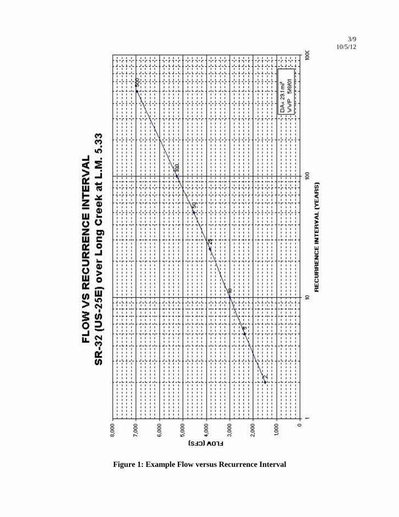
7. Plot discharge vs. recurrence interval curve as shown in Figure 1. 8. Determine the average flood energy grade slope for a reach upstream and downstream of the
site. This slope is usually approximately equal to the average streambed slope for that same reach. Using multiple methods such as USGS quadrangle maps, site survey, and flood insurance studies to determine this slope is recommended.
9. The skew of the culvert or the skew of the bridge substructures should be in alignment with the
direction of design flood flow downstream of the proposed structure. This will generally be with the flood plain skew or the channel skew whichever is more site appropriate.
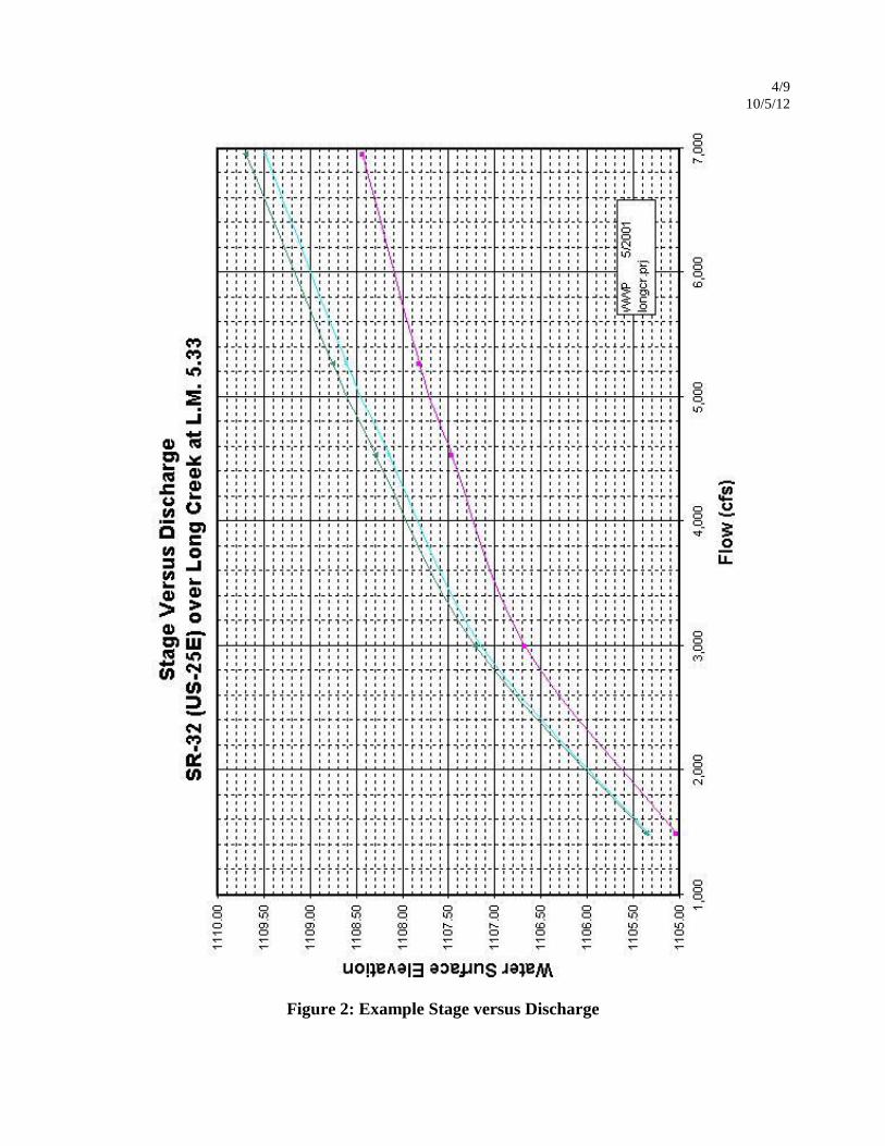
10. Run a water surface profile model in HEC-RAS to determine the normal water surface profiles, the existing bridge water surface profiles and the proposed bridge water surface profiles along with any alternatives for the 2, 10, 50, 100, and 500 year events. If the bridge location is within a FEMA designated floodway and an existing HEC-2 model is available from FEMA, TVA, or the Corps of Engineers, then import the HEC-2 model into HEC-RAS. Create a stage vs. discharge curve as shown in Figure 2. This curve should show all three water surface profiles and any alternatives at the upstream cross-section with highest proposed backwater.
2/9
10/5/12
11. See Tennessee Hydraulics Memorandum - 01 “Box and Slab Culverts and Bridges” for
determination of the type of structure required at the design site.
12. For guidelines on selecting an acceptable structure size, refer to the following Tennessee Hydraulics Memorandums: A. “Design of Waterway Openings” - 03 B. “Improved Inlets and Energy Dissipaters for Culverts and Box or Slab Bridges” -06 C. “Scour and Fill at Bridge Waterways” - 08
13. Proper drainage of rainfall on the bridge deck shall be provided. See Tennessee Hydraulics
Memorandum - 07 “Drainage of Bridge Decks”.
14. Where Rip-Rap is required for slope protection, refer to Tennessee Hydraulics Memorandum - 09 “Rip-Rap for Bridge Waterways, Open Channels and Grade Crossings”.
15. The proposed bridge plans may be subject to approval by various other agencies. See Tennessee Hydraulics Memorandum - 05 “Approval of Bridge Plans by Outside Agencies”.
16. An on site visual inspection should be made of the existing hydraulic conditions. See
Tennessee Hydraulics Memorandum - 10 “On Site Inspection Report” for specific details of the inspection.
17. Compile the hydraulic design file. 18. The roadway designer should submit roadway plans to the Environmental Division in order to
determine permit requirements and for permit application. See Roadway Design Guidelines and Tennessee Hydraulics Memorandum - 05 "Approval of Bridge Plans by Outside Agencies" for details.
3/9
10/5/12
Figure 1: Example Flow versus Recurrence Interval
4/9
10/5/12
Figure 2: Example Stage versus Discharge

5/9
10/5/12
Hydraulic Design Responsibility
The Hydraulic Design and Permitting Section will be responsible for the hydraulic design of stream
encroachments (bridges, culverts, channels, etc.) where the Q50 is greater than 500 ft3/s (14 m
3/s)
(by the USGS regression equations) at the downstream most portion of the encroachment.
Additionally, replacement or rehabilitation of any existing structure 20 feet (6 m) long or longer or
structures on streams with a detailed FEMA Flood Insurance Study will be reviewed by the
Hydraulic Design Section and a determination of hydraulic design responsibility will be made.
The roadway designer will submit to this office preliminary plans (typical sections, present and
proposed layout, and profile, cross sections, etc.), location map, and survey information as indicated
in the Drainage Surveys Section of the Survey Manual for all stream encroachments (bridges,
culverts, channels, etc.) whose Q50 is greater than 500 ft3/s (14 m
3s) (by the USGS regression
equations) at the downstream most portion of the encroachment and for replacement or
rehabilitation of any existing structure 20 feet (6 m) long or longer.
The Design Division will be notified by the scheduled grade approval date or within 30 days of
receipt of a complete grade approval request (whichever is longer) of the finished grade
requirements for the stream encroachment.
For the replacement or rehabilitation of any existing structure 20 feet (6 m) long or longer or
structures on streams with a detailed FEMA Flood Insurance Study, the Design Division will be
notified whether the hydraulic design will be completed in this office or if they should proceed with
replacement under their hydraulic design criteria.
Where removal of a portion of an existing structure is required for stage construction, the plans
should be forwarded to the appropriate Manager 2 in the Structural Design Section of the Structures
Division for review and a request for stage construction details that will affect roadway design
should be made.
The final hydraulic data and any additional drawings required to complete plans for the stream
encroachment will be forwarded to the Design Division no later than the scheduled complete
hydraulics due date. At this time a Hydraulic Preliminary Layout should be forwarded to the
Director of Structures Division for structural design assignment.
6/9
10/5/12
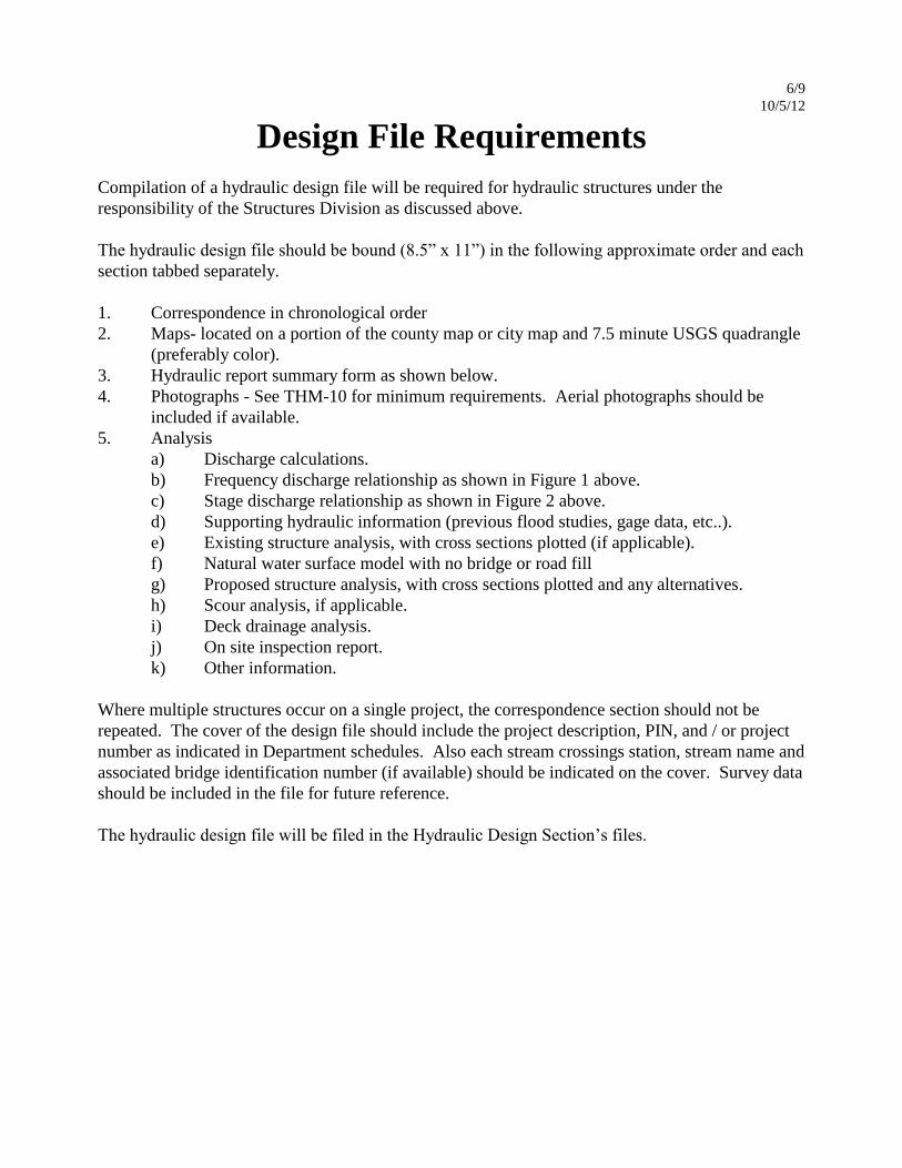
Design File Requirements
Compilation of a hydraulic design file will be required for hydraulic structures under the
responsibility of the Structures Division as discussed above.
The hydraulic design file should be bound (8.5” x 11”) in the following approximate order and each
section tabbed separately.
1. Correspondence in chronological order
2. Maps- located on a portion of the county map or city map and 7.5 minute USGS quadrangle
(preferably color).
3. Hydraulic report summary form as shown below.
4. Photographs - See THM-10 for minimum requirements. Aerial photographs should be
included if available.
5. Analysis
a) Discharge calculations.
b) Frequency discharge relationship as shown in Figure 1 above.
c) Stage discharge relationship as shown in Figure 2 above.
d) Supporting hydraulic information (previous flood studies, gage data, etc..).
e) Existing structure analysis, with cross sections plotted (if applicable).
f) Natural water surface model with no bridge or road fill
g) Proposed structure analysis, with cross sections plotted and any alternatives.
h) Scour analysis, if applicable.
i) Deck drainage analysis.
j) On site inspection report.
k) Other information.
Where multiple structures occur on a single project, the correspondence section should not be
repeated. The cover of the design file should include the project description, PIN, and / or project
number as indicated in Department schedules. Also each stream crossings station, stream name and
associated bridge identification number (if available) should be indicated on the cover. Survey data
should be included in the file for future reference.
The hydraulic design file will be filed in the Hydraulic Design Section’s files.

7/9
10/5/12
STATE OF TENNESSEE
DEPARTMENT OF TRANSPORTATION - DIVISION OF STRUCTURES
HYDRAULIC REPORT
Date: Designer:_______________
A. SITE DATA
1. LOCATION
a. Name of Stream: _______________________ Channel Mile: ______________________
b. Route Name: _______________________ P.E. No.: ______________________
c. Route No.: _______________________ Project No.: ______________________
d. County: _______________________ USGS Quad #: ______________________
e. City: _______________________ Name: ______________________
2. VICINITY
a. See attached location map or bridge survey.
b. Nature of Stream Bed:
c. Bank subject to Erosion: Severe = 10 Stable = 0
d. Should Drift be a consideration: Extreme = 10 No = 0
3. EXISTING BRIDGE DATA
a. Bridge Location No.: ______________________ ______________________
b. Bridge Selection No.: ______________________ ______________________
b. Drawing No.: ______________________ ______________________
c. Bridge Length: ft. ft.
d. Bridge Width: ft. ft.
e. Bridge Type: _______________ _______________
f. Bridge Skew: ° °
g. Drainage Area: mi2. mi
2.
h. Design Discharge: ft3/s ft
3/s
i. Design Frequency: Year Year
j. Design Water Area: ft.2 ft.
2
k. Design Elevation: ft. ft.
l. Design Backwater: ft. ft.
m. Design Velocity: ft/s ft/s
n. Overtopping El.: ft. ft.
4. EXISTING WATER STAGES AT PROPOSED BRIDGE SITE
a. Maximum High Water El.: Date: / /
Frequency: year Source:
b. Year High Water Elevation: ft.
c. Datum Elevation: ft. Ordinary High Water Elevation: ft.
d. In Reservoir (Y/N): _ Reservoir Name: ___________________
Normal Pool Elevation: ft. Minimum Pool Elevation: ft.
e. Backwater Elevation: ft. From: __________

8/9
10/5/12
B. HYDROLOGICAL ANALYSIS
1. FLOOD RECORDS
a. Floods in Tennessee - Magnitude and Frequency - 2003 [ ] U.S.G.S. [ ]
Corps of Engineers [ ] TVA [ ] Other [ ] ____________________
b. Stream Gage No.: At Site [ ] In Vicinity [ ]
c. None Available [ ]
2. DRAINAGE AREA
a. ____________ sq. mi. Calculated: _____ Published: ___
3. DISCHARGE
a. Magnitude: _______ _______ ________ ______ ________ ________ _______
Frequency: 2 yr 5 yr 10 yr 25 yr 50 yr 100 yr 500 yr
b. Proposed Overtopping: Frequency year & Discharge cfs
c. Source: _________ Floods in Tennessee - Magnitude and Frequency – 2003
_________ Corps of Engineers
_________ TVA
_________ Federal Insurance Study __________ County or City
_________ Other
4. STREAM SLOPE
a. From U.S.G.S. Quad Map: ft./ft.
b. From Site Survey Data: ft./ft.
c. From Flood Flow Profiles: _____________________
C. HYDRAULIC ANALYSIS OF PROPOSED BRIDGE
1. PROPOSED STRUCTURE
a. Station: Drainage Area: mi.2.
Design Frequency: year Design Discharge: ft3/s
Design Velocity: ft/s Design Bridge Backwater: ft.
Design Bridge Backwater El: ft. Roadway Overtopping Elevation: ft.
Design Waterway Area: ft.2 below elev. ft.
b. Is Bridge Backwater a consideration? (Y/N) :
Year Bridge Backwater: ft.
Year Bridge Backwater Elevation: ft.
Describe Control: _________________________________________________________________________
c. Are Spur Dikes Needed (Y/N) : _
Describe Reason: _________________________________________________________________________
d. Is Channel Transitioning Involved (Y/N) : See attached detail.
e. Is Channel Change Involved (Y/N) : See attached detail.
f. Is Bank Protection Needed (Y/N) : See attached detail.
g. Final Layout: See Drawing No. ________________
9/9
5/5/97
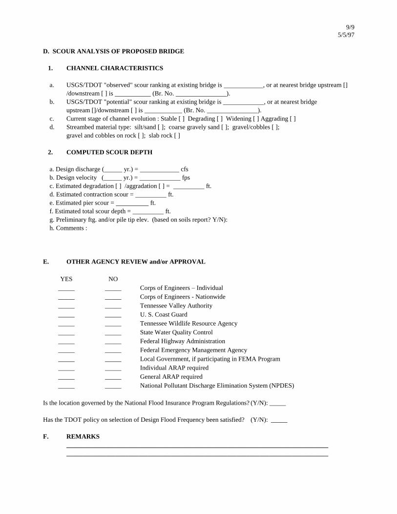
D. SCOUR ANALYSIS OF PROPOSED BRIDGE
1. CHANNEL CHARACTERISTICS
a. USGS/TDOT "observed" scour ranking at existing bridge is , or at nearest bridge upstream []
/downstream [ ] is (Br. No. ).
b. USGS/TDOT "potential" scour ranking at existing bridge is , or at nearest bridge
upstream []/downstream [ ] is (Br. No. ).
c. Current stage of channel evolution : Stable [ ] Degrading [ ] Widening [ ] Aggrading [ ]
d. Streambed material type: silt/sand [ ]; coarse gravely sand [ ]; gravel/cobbles [ ];
gravel and cobbles on rock [ ]; slab rock [ ]
2. COMPUTED SCOUR DEPTH
a. Design discharge ( yr.) = cfs
b. Design velocity ( yr.) = fps
c. Estimated degradation [ ] /aggradation [ ] = ft.
d. Estimated contraction scour = ft.
e. Estimated pier scour = ft.
f. Estimated total scour depth = ft.
g. Preliminary ftg. and/or pile tip elev. (based on soils report? Y/N):
h. Comments :
E. OTHER AGENCY REVIEW and/or APPROVAL
YES NO
_____ _____ Corps of Engineers – Individual
_____ _____ Corps of Engineers - Nationwide
_____ _____ Tennessee Valley Authority
_____ _____ U. S. Coast Guard
_____ _____ Tennessee Wildlife Resource Agency
_____ _____ State Water Quality Control
_____ _____ Federal Highway Administration
_____ _____ Federal Emergency Management Agency
_____ _____ Local Government, if participating in FEMA Program
_____ _____ Individual ARAP required
_____ _____ General ARAP required
_____ _____ National Pollutant Discharge Elimination System (NPDES)
Is the location governed by the National Flood Insurance Program Regulations? (Y/N): _____
Has the TDOT policy on selection of Design Flood Frequency been satisfied? (Y/N): _____
F. REMARKS
________________________________________________________________________________
________________________________________________________________________________

THM-01 1/4
11/16/12
TENNESSEE HYDRAULICS MEMORANDUM - 01
Box and Slab Culverts and Bridges
Distribution: Office, Consultants
Definitions for Cast-In-Place & Precast Concrete and Corrugated Metal Structures
Box Culvert - A box type structure consisting of a single box or multiple boxes with a bottom slab, having a length
measured along the centerline of the roadway of less than 20 feet (6.1 m) between the extreme ends of the openings.
Slab Culvert - A structure consisting of a single box or multiple boxes without a bottom slab, having a length measured
along the centerline of the roadway of less than 20 feet (6.1 m) between the extreme ends of the openings.
Box Bridge - A box culvert type structure consisting of a single box or multiple boxes with a bottom slab, having a
length measured along the centerline of the roadway of more than 20 feet (6.1 m) between the extreme ends of the
openings.
Slab Bridge - A structure consisting of a single box or multiple boxes without a bottom slab, having a length measured
along the centerline of the roadway of more than 20 feet (6.1 m) between the extreme ends of the openings.
Girder Bridge - A structure erected over a stream, watercourse, highway, railroad or opening, for carrying traffic,
having a length measured along the centerline of the roadway of more than 20 feet (6.1 m) between the faces of the end
supports and consisting of a distinct superstructure and substructure.
Precast Concrete Arch – A precast arch structure of varying shape consisting of one or more barrels that can be
constructed on precast or cast in place strip footings, pile supported strip footings or a concrete bottom as required by
site conditions.
Corrugated Metal Arch - A steel or aluminum arch structure of varying shape consisting of one or more barrels that can
be constructed on precast or cast in place strip footings, pile supported strip footings or a concrete bottom as required
by site conditions.
The distinction between Culverts, Box Bridges and Girder Bridges is important in that separate bid items for concrete
and reinforcing are provided for each. See SMO13-04 and Tennessee Standard Specifications Articles 101.07, 101.08
and 604.32. Pre-cast concrete or metal structures are often bid lump sum.
The distinction between slabs and boxes is important in that it establishes whether or not the structure has a bottom
slab. When the foundation for the structure is capable of providing sufficient bearing resistance and is a non-erodible
material such as suitable bedrock then the bottom slab is replaced by a small footing to support the walls of the
structure forming a three sided structure. When the foundation material is erodible, the bottom slab serves as the
structure foundation and is a complete four sided structure.
In cases where a box is specified and suitable rock is within three feet of the streambed, the field engineer may
substitute a slab structure and vice versa when rock is not available as anticipated. Leveling concrete may be used for
uneven bedrock in some situations.
Precast concrete arch or metal arch structures should be considered for use when environmental impacts dictate
spanning a stream that is not necessarily large enough to warrant a girder bridge but prohibits the use of a box or slab
bridge, aesthetic issues such as high visibility to a neighborhood, public park, or historic area, and/or time of
construction is an issue and can be improved over a cast in place structure.

THM-01 2/4
11/16/12
Available Standards
Box and Slab Culverts and Bridges are primarily used to provide roadway crossings for small streams. They are also
used as cattle and machinery passes. Openings are sized to suit their intended use. Stream crossings are sized based on
the hydraulic design as described in THM-03. A large selection of standard box and slab culverts, improved inlets, and
energy dissipaters has been developed and are on file in the Division of Structures. An index of all available box and
slab standard drawings is maintained by the Division of Structures on the TDOT website.
Standards are available for a wide variety of barrel heights and widths, number of barrels, skews and fill heights.
Barrel widths of 6 feet to 18 feet increasing in 2 feet intervals are available in single, double and triple barrels. The
barrel heights vary from 4 feet up to a height equal to a single barrel width increasing in increments of 1 foot. These
combinations provide a size range from a single 6' x 4' to a three at 18' x 18' with corresponding single openings
ranging from 24 square feet to 324 square feet respectively. More than three barrels at any one crossing should be
avoided for debris accumulation and cost issues unless site conditions specifically call for more than three barrels. The
hydraulic characteristics for a culvert may be improved with special inlet details. See THM-06 for details on improved
culvert inlets.
Culvert end skews are available for 45°, 60°, 75° and 90°. Although the field engineer will construct the box to the
exact skew (the angle between the centerline of the culvert and the centerline of the road) of the crossings the design
and details of the closest available culvert end skew may be used for estimations.
Standard details also vary depending on the amount of fill to be placed on the box. Fill height shown on the standard
drawings is measured from the bottom of the top slab to the top of the fill. When the fill height is less than one foot the
"No Fill" section shown on the standard drawings may be used. Details are available for fill heights of 3 feet, 5 feet,
and 10 feet to 60 feet (increasing in increments of 10 feet).
Use of old standards for extensions of box or slab culverts or bridges that are no longer standard sizes such as 15’x15’
or where the height is larger than the span, should be avoided where possible and limited in all cases to fill heights less
than 10 feet. Current standards may be used with 1:1 transitions to the height and span.
The proper way to designate a box is to list, in order, the number of barrels, barrel width, height, skew and fill height.
For instance, a 3 @ 10' x 8' @ 45° and 30 feet of fill would be three barrels each 10 feet wide and 8 feet high skewed
45° and designed for a 30 feet high fill.
Other standards will be developed as necessary to provide skews, openings or fill heights not available on the current
list of standards.
Quantities and Cost Estimates
The quantities shown on the standards are given per foot of box length for each combination of culvert height and fill
section. Quantities for wings, cut-off walls, debris deflection walls, and edge beams are shown on separate drawings.
See Structures Memorandum 013 for instructions regarding cost estimates for boxes and slabs.
Contract Drawings and Specifications
Roadway plans in the contract drawings show the location, skew, elevation, size, fill height and Standard Drawings
applicable for the construction of each box or slab. The location is shown on the roadway plan and profile. The length,
elevations and fill height are shown in a roadway cross section. The project engineer has some flexibility in adjusting
the location to fit field conditions unless otherwise noted on the plans.
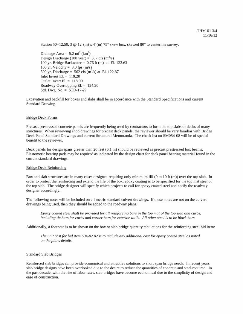
All hydraulic data for Bridges and Culverts shall be shown on the roadway plan profile sheet as follows:
THM-01 3/4
11/16/12
Station 50+12.50, 3 @ 12' (m) x 4' (m) 75° skew box, skewed 80° to centerline survey.
Drainage Area = 5.2 mi2 (km
2)
Design Discharge (100 year) = 387 cfs (m3/s)
100 yr. Bridge Backwater = 0.76 ft (m) at El. 122.63
100 yr. Velocity = 3.0 fps (m/s)
500 yr. Discharge = 562 cfs (m3/s) at El. 122.87
Inlet Invert El. = 119.20
Outlet Invert El. = 118.90
Roadway Overtopping El. = 124.20
Std. Dwg. No. = STD-17-??
Excavation and backfill for boxes and slabs shall be in accordance with the Standard Specifications and current
Standard Drawing.
Bridge Deck Forms
Precast, prestressed concrete panels are frequently being used by contractors to form the top slabs or decks of many
structures. When reviewing shop drawings for precast deck panels, the reviewer should be very familiar with Bridge
Deck Panel Standard Drawings and current Structural Memoranda. The check list on SM054-08 will be of special
benefit to the reviewer.
Deck panels for design spans greater than 20 feet (6.1 m) should be reviewed as precast prestressed box beams.
Elastomeric bearing pads may be required as indicated by the design chart for deck panel bearing material found in the
current standard drawings.
Bridge Deck Reinforcing
Box and slab structures are in many cases designed requiring only minimum fill (0 to 10 ft (m)) over the top slab. In
order to protect the reinforcing and extend the life of the box, epoxy coating is to be specified for the top mat steel of
the top slab. The bridge designer will specify which projects to call for epoxy coated steel and notify the roadway
designer accordingly.
The following notes will be included on all metric standard culvert drawings. If these notes are not on the culvert
drawings being used, then they should be added to the roadway plans.
Epoxy coated steel shall be provided for all reinforcing bars in the top mat of the top slab and curbs,
including tie bars for curbs and corner bars for exterior walls. All other steel is to be black bars.
Additionally, a footnote is to be shown on the box or slab bridge quantity tabulations for the reinforcing steel bid item:
The unit cost for bid item 604-02.02 is to include any additional cost for epoxy coated steel as noted
on the plans details.
Standard Slab Bridges
Reinforced slab bridges can provide economical and attractive solutions to short span bridge needs. In recent years
slab bridge designs have been overlooked due to the desire to reduce the quantities of concrete and steel required. In
the past decade, with the rise of labor rates, slab bridges have become economical due to the simplicity of design and
ease of construction.

THM-01 4/4
11/16/12
There is also an environmental benefit to having a natural bottom in the culvert as three sided structures have gained
favor with the permitting agencies.
Slab bridges also allow much shallower superstructure depths requiring less approach fill. Slab bridges are
economically competitive for spans up to 54 feet (16 m).
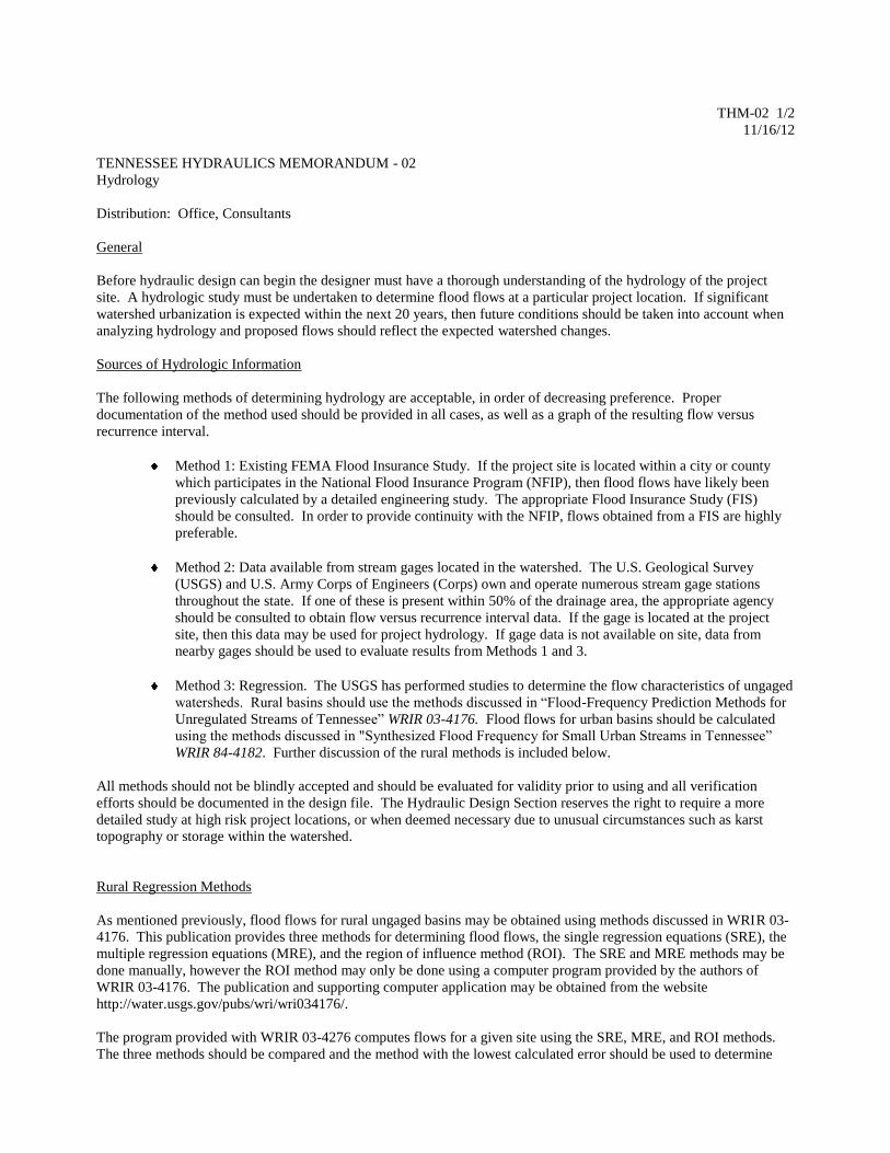
THM-02 1/2
11/16/12
TENNESSEE HYDRAULICS MEMORANDUM - 02
Hydrology
Distribution: Office, Consultants
General
Before hydraulic design can begin the designer must have a thorough understanding of the hydrology of the project
site. A hydrologic study must be undertaken to determine flood flows at a particular project location. If significant
watershed urbanization is expected within the next 20 years, then future conditions should be taken into account when
analyzing hydrology and proposed flows should reflect the expected watershed changes.
Sources of Hydrologic Information
The following methods of determining hydrology are acceptable, in order of decreasing preference. Proper
documentation of the method used should be provided in all cases, as well as a graph of the resulting flow versus
recurrence interval.
Method 1: Existing FEMA Flood Insurance Study. If the project site is located within a city or county
which participates in the National Flood Insurance Program (NFIP), then flood flows have likely been
previously calculated by a detailed engineering study. The appropriate Flood Insurance Study (FIS)
should be consulted. In order to provide continuity with the NFIP, flows obtained from a FIS are highly
preferable.
Method 2: Data available from stream gages located in the watershed. The U.S. Geological Survey
(USGS) and U.S. Army Corps of Engineers (Corps) own and operate numerous stream gage stations
throughout the state. If one of these is present within 50% of the drainage area, the appropriate agency
should be consulted to obtain flow versus recurrence interval data. If the gage is located at the project
site, then this data may be used for project hydrology. If gage data is not available on site, data from
nearby gages should be used to evaluate results from Methods 1 and 3.
Method 3: Regression. The USGS has performed studies to determine the flow characteristics of ungaged
watersheds. Rural basins should use the methods discussed in “Flood-Frequency Prediction Methods for
Unregulated Streams of Tennessee” WRIR 03-4176. Flood flows for urban basins should be calculated
using the methods discussed in "Synthesized Flood Frequency for Small Urban Streams in Tennessee”
WRIR 84-4182. Further discussion of the rural methods is included below.
All methods should not be blindly accepted and should be evaluated for validity prior to using and all verification
efforts should be documented in the design file. The Hydraulic Design Section reserves the right to require a more
detailed study at high risk project locations, or when deemed necessary due to unusual circumstances such as karst
topography or storage within the watershed.
Rural Regression Methods
As mentioned previously, flood flows for rural ungaged basins may be obtained using methods discussed in WRIR 03-
4176. This publication provides three methods for determining flood flows, the single regression equations (SRE), the
multiple regression equations (MRE), and the region of influence method (ROI). The SRE and MRE methods may be
done manually, however the ROI method may only be done using a computer program provided by the authors of
WRIR 03-4176. The publication and supporting computer application may be obtained from the website
http://water.usgs.gov/pubs/wri/wri034176/.
The program provided with WRIR 03-4276 computes flows for a given site using the SRE, MRE, and ROI methods.
The three methods should be compared and the method with the lowest calculated error should be used to determine

THM-02 2/2
11/16/12
flood flows for the structure. In certain cases, the program calculates outlier flows which it then corrects using a linear
interpolation method (see WRIR 03-4276 for further detail). We do not recommend using this method for design. In
certain high risk situations where conservative design is warranted the method resulting in the highest flows may be
used rather than the method resulting in the lowest errors.
The USGS Streamstats web based program provides the drainage area, hydrologic area, watershed slope and flows for
the MRE method. The SRE method flows are given where gaps in the MRE exist. This application may be used for
most locations in Tennessee if the site is large enough to be included in the state GIS hydrology dataset. Exceptions are
in the Mississippi River flood plain and in karst areas where the information should be checked by other sources.
THM-03 1/5
10/5/12
TENNESSEE HYDRAULICS MEMORANDUM - 03
Design of Waterway Openings
Distribution: Office, Consultants
General
Bridges and culverts should provide waterway openings which will not produce excessive backwater or scouring
velocities. The minimum structure length should be that which will bridge the natural or man-made stream channel.
The structure should be designed so that the accumulation of debris on the structure is minimized.
Design Frequency Criteria
The minimum "design flood" magnitude for stream crossings on State Routes is the 10 year frequency runoff and for
Interstates and other 4 or more lane routes it is the 100 year frequency runoff. An analysis using the design condition is
made of the flood risk to the highway, and the effect of the proposed crossing on the possible damages to surrounding
property, the stream stability and the environment. Drainage facilities for Off-System and/or low traffic volume
systems may be based on lesser floods if the conditions of the site warrant lower standards. The selection of the
"design flood" includes consideration of construction cost analysis, probable property damage, the cost of traffic
delays, the availability of alternate routes, emergency supply and evacuation routes, the potential loss of life and
budgetary constraints.
The interstates were originally designed for a 50 year flood frequency. That should now be upgraded to the 100 year
frequency as with other 4 or more lane routes when economically feasible and constructible. The Design Division
should be consulted to help determine this feasibility and applicability to the project.
When hydraulic structures are required on existing routes, the existing roadway grade may not be suited to being raised
to desired design frequency. In this case a design exception would be required. See ADDENDUM of THM-03.
The hydraulic design for bridge crossings and/or encroachments shall be consistent with standards established by the
Federal Emergency Management Agency and local governments for the administration of the National Flood Insurance
Program.
Peak discharges should be reduced when floodwater retarding structures and/or reservoir systems are "existing"
upstream from the bridge crossing, or can be expected to be in service upon completion of the highway construction.
The appropriate Flood Control Agency should be contacted for computation of the reduced discharge.
Bridge Openings
Waterway openings should be designed to keep scour in the main channel and the overbanks within reasonable limits
for which the bridge may be designed to withstand. It should be able to pass the 500 year flood without causing
structural failure.
Backwater computations must be made to determine backwater caused by the bridge constriction. Generally, for the
design flood event, the bridge opening should not create more than a one foot (0.3 m) differential in water levels
between the normal water surface elevation, with no roadway fill or structure present, and the proposed water surface
elevation, with the proposed roadway fill and structure present. Land development at the site or other topography may
fix the allowable headwater elevations. Surrounding bridges will also influence the structure location and waterway
area selected and in some cases analysis of these surrounding bridges may be required in addition to the project bridge.
Roadway grades shall provide a minimum clearance of 1 feet (0.3 m) between the design flood and low girder
elevations, except in cases where cost constraints or vertical geometry controls dictate a lower profile.
In addition to the above flood design criteria, structure clearances must satisfy any requirements set by the U. S. Coast
Guard, the Corps of Engineers, or the Tennessee Valley Authority where the site falls within the jurisdiction of any of
THM-03 2/5
10/5/12
these agencies. The Tennessee Valley Authority and the Corps of Engineers will exercise their reviewing authority in
some locations where flood control measures have been taken, or, are in the planning stage.
Culvert Openings
The selection of opening size for box bridges and culverts is normally based on the following guidelines:
1. The culvert shall not create more than one foot (0.3 m) differential in water levels between the normal water
surface elevation, with no roadway fill or structure present, and the proposed water surface elevation, with the
proposed roadway fill and structure present, unless flood damage due to the increased water level is
insignificant.
2. If outlet velocities exceed what the natural streambed can withstand, then a larger culvert opening may be
required. If increased culvert size is not feasible, then streambed protection shall be provided. Energy
dissipaters may be required when outlet velocities exceed 15 fps.
Hydraulic Data Requirements
Hydraulic data will be required to be shown for every hydraulic structure. This hydraulic data is to be located on the
roadway profile sheet for culverts and on the bridge layout sheet for bridges. The Hydraulic Data is as follows:
1. Culverts: (See THM-01)
2. Bridges:
A. Single Bridge Crossing:
Drainage Area = 7.8 mi2 (km
2)
Design Discharge (100 year) = 568 cfs (m3/s)
Water Area Provided Below El. 125.28 = 43.4 ft2
(m2)
100 Year Velocity = 1.3 fps (m/s)
100 Year Bridge Backwater = 0.14 ft (m) @ El. 125.47
500 Year Discharge = 769 cfs (m3/s) @ El. 125.80
Roadway Overtopping El. = 127.30
B. Multi Bridge Crossing:
Drainage Area = 7.8 mi2 (km
2)
Design Discharge (100 year)
Total = 113.4 cfs (m3/s)
Thru this Bridge = 568 cfs (m3/s
Water Area Provided Below El. 125.28 = 43.4 ft2 (m
2)
100 Year Velocity = 1.3 fps (m/s)
100 Year Bridge Backwater = 0.14 ft (m) @ El. 125.47
500 Year Discharge (Total) = 769 cfs (m3/s) @ El. 125.80
Roadway Overtopping El. = 127.30
Temporary Run-Arounds
Temporary run-arounds should be designed to pass a 2 year flood without substantial flood damage or without
overtopping the run-around. Site conditions may merit a higher frequency design. Requests from the Environmental or
Construction Divisions should be made to justify a higher design.

THM-03 3/5
10/5/12
References
For more specific information regarding other hydraulic design and details refer to Tennessee Hydraulics
Memorandums - 04, 05, 06, 07, 08 and 09.
See also Federal Highway Manuals - Hydraulic Engineering Circular No. 17 (HEC-17), Hydraulic Design Series No. 5
(HDS-5), HEC-18, HEC-20 and Hydraulics of Bridge Waterways.
THM-03 4/5
10/5/12
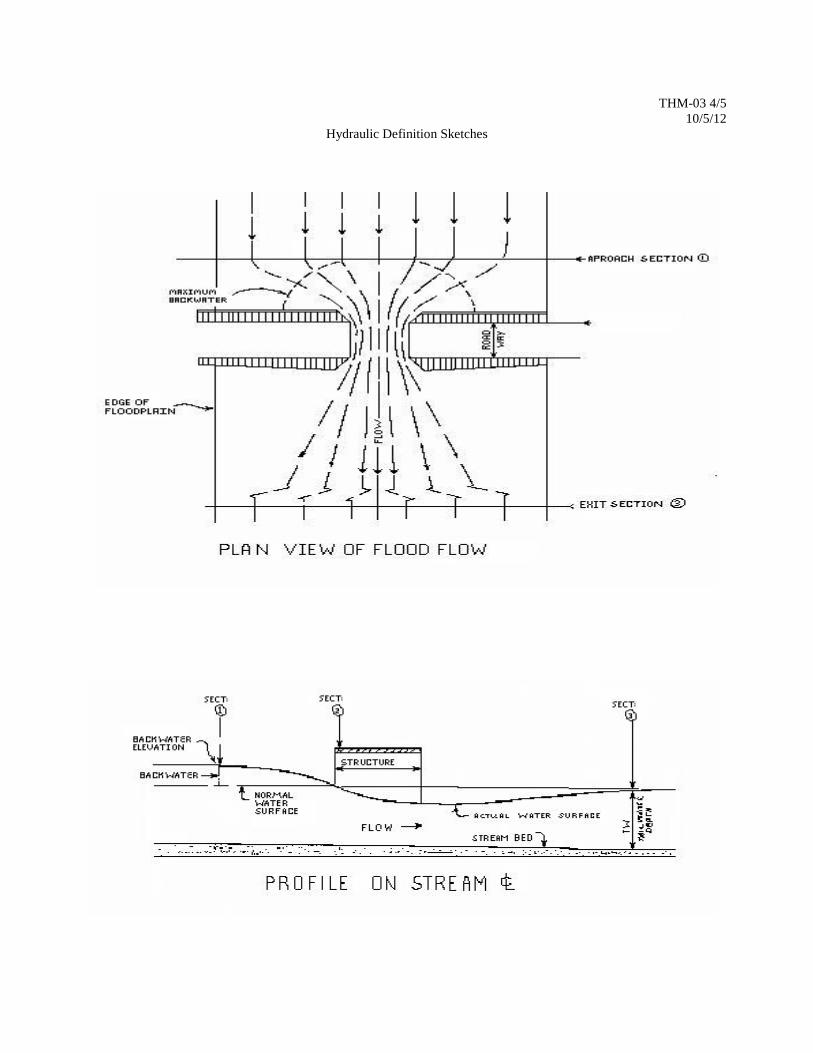
Hydraulic Definition Sketches

THM-03 5/5
10/5/12
ADDENDUM
Flood Design Policies for Roads & Bridges
Tennessee Department of Transportation
The following conditions may be considered as exceptions to State Route Design Frequency as identified on page 1 of
THM-03.
1. A bridge and approach project located in a wide flood plain (e.g. West Tennessee) at which the present road
profile is subject to frequent overtopping. Raising the present grade would drastically increase the length
and cost of the project.
2. A bridge replacement design involving a frequently flooded (more often than 10-year intervals) route and
land developments located at the site in a flood-prone area. Raising the road level to suit a 10-year high
water frequency would increase potential damage to the property owner.
3. The proposed project intersects another route in which both are frequently flooded by less than a 10-year
occurrence. Land developments in a flood-prone area are impacted.
4. The present road is frequently flooded at the bridge to be replaced as well as various other locations along
the route. No betterment for the route is anticipated in the foreseeable future. Higher type road service at
one location only would not improve the road operation.
5. A project to widen or rehabilitate an existing structure at a location where the waterway opening and/or
overtopping elevation is not suitable to provide for a 10-year flood frequency.
General Guidelines:
Exceptions to the minimum design for the 10-year flood is only justified under unusual site conditions which are
defined above and in which careful consideration has been given to traffic volume, available detour in case of high
water, cost increase above replacement-in-kind, expected maintenance and the increased hazard to the driver at the
location.

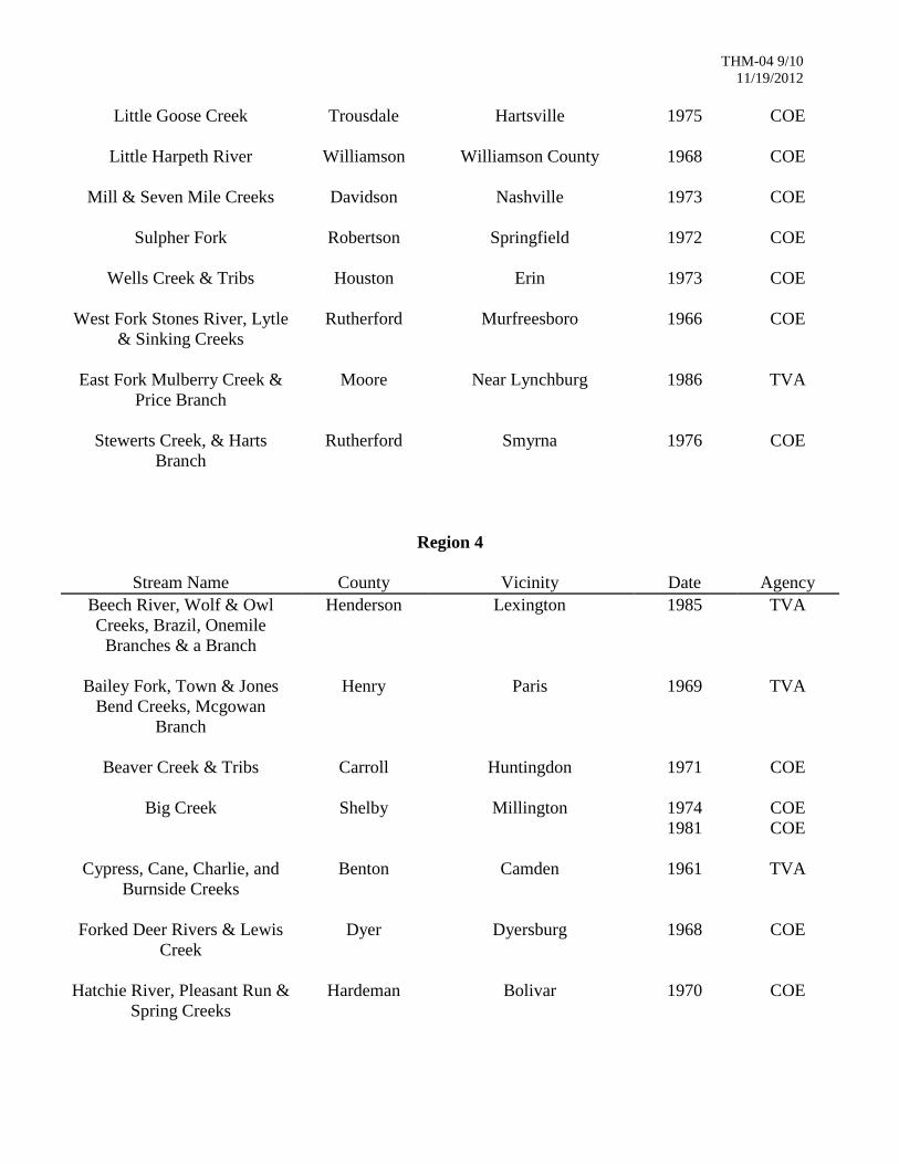
THM-04 1/10
11/19/2012
TENNESSEE HYDRAULICS MEMORANDUM - 04
Index of Local Flood Studies by TVA, Corps of Engineers, USGS and FEMA Flood Insurance Studies
Distribution: Office, Consultants
The attached index of flood reports lists those reports that are kept in our hydraulic library and are available to the
public through the authoring agency. Additional studies will be added to the list as they become available.
NOTE: The Division files are for the use of Department personnel only. The Division is not to be considered a library
for public use. The following lists are for general information purposes. Data from these reports should be requested
through the respective agency and used for historical purposes only.
A paper copy of many of the TRB NCHRP publications is kept in the hydraulic library on various hydraulic design and
maintenance related topics. They are available to the public through the TRB website often in PDF format.
Paper copies of the FEMA Flood Insurance Studies (FIS) and Flood Insurance Rate Maps (FIRMs) are housed in the
Hydraulic Design Section however the most up to date and some historical maps and studies can be found on the
FEMA website at the Map Service Center link. Paper copies of the FIS and FIRMs may also be obtained from the
applicable city or county or the Tennessee Department of Economic and Community Development (TECD). The state
also maintains the FIRMs in GIS format. Requests for GIS data can be made through the TDOT IT Division.

THM-04 2/10
11/19/2012
Flood Studies by Various Agencies
Region 1
Stream Name County Vicinity Date Agency
Brush Creek
Washington Johnson City 1959 TVA
Doe River & Tributary Creeks
Carter Roane Mountain
1961 TVA
French Broad & Pigeon River
Cocke Newport
1958 TVA
Little Limestone Creek Washington Jonesboro
1970 TVA
Little Pigeon River & Dudley
Creek
Sevier Gatlinburg
1974 TVA
Nolichucky River and North
and South Indian Creeks
Unicoi Erwin
1967 TVA
Streams
Carter Near Elizabethton
1967 TVA
Sweetwater Creek
Monroe Sweetwater
1958 TVA
Tellico River & Hunt Branch
Monroe Tellico Plains
1966 TVA
Town, Goose, and Furnace
Creeks
Johnson Mountain City
1967 TVA
Watauga and Doe Rivers
Carter Elizabethton
1957 TVA
Large Springs
-- Valley & Ridge Province
1990 USGS
Streams
Unicoi Erwin
1966 TVA
French Broad, Little, &
Hiawassee Rivers
-- Upper River Basins
1965 TVA
Love Creek Drainage Knox Knoxville
1983 UTK
West Prong Little Pigeon
River, Roaring, Baskins, and
Leconte Creeks
Sevier Gatlinburg
1982 TVA
Ten Mile & Sinking Creeks
Knox Knox County
1973 TVA
First Creek
Knox Knoxville
1967 COE

THM-04 3/10
11/19/2012
Beaver Creek
Sullivan Bristol, VA - TN
1956
1959
TVA
TVA
Big Creek
Campbell LaFollette
1958 TVA
Bull Run & Hinds Creek
Anderson Anderson County 1965 TVA
Clinch River Anderson Clinton 1955
1956
TVA
TVA
Clinch River Anderson Oak Ridge 1957 TVA
Clinch River & Blackwater
Creek
Hancock Sneedville
1969 TVA
Clinch River & East Fork
Popular Creek
Anderson Oak Ridge
1959
1968
TVA
TVA
Coal Creek Anderson Briceville & Lake City
1962 COE
Coal Creek & Tributaries Anderson Lake City
1968 TVA
Dog Creek Campbell Jacksboro
1971 TVA
Holston River, Big Creek, and
Caney Creek
Hawkins Rogersville
1961 TVA
Holston River Hawkins Surgoinsville & Church
Hill
1961 TVA
Little Pigeon & West Fork
Little Pigeon Rivers
Sevier Sevierville
1958 TVA
Mossey Creek
Jefferson Jefferson City
1965 TVA
North Fork Bull Run Creek
Union Maynardville
1966 TVA
Reedy Creek
Sullivan Kingsport
1955
1956
1957
1960
TVA
TVA
TVA
TVA
Russell Creek
Claiborne Tazwell- New Tazwell
1968 TVA
South Fork Holston River @
Long Island
Sullivan Kingsport
1955
1956
1960
TVA
TVA
TVA
Streams
Hamblen Near Morristown
1957 TVA
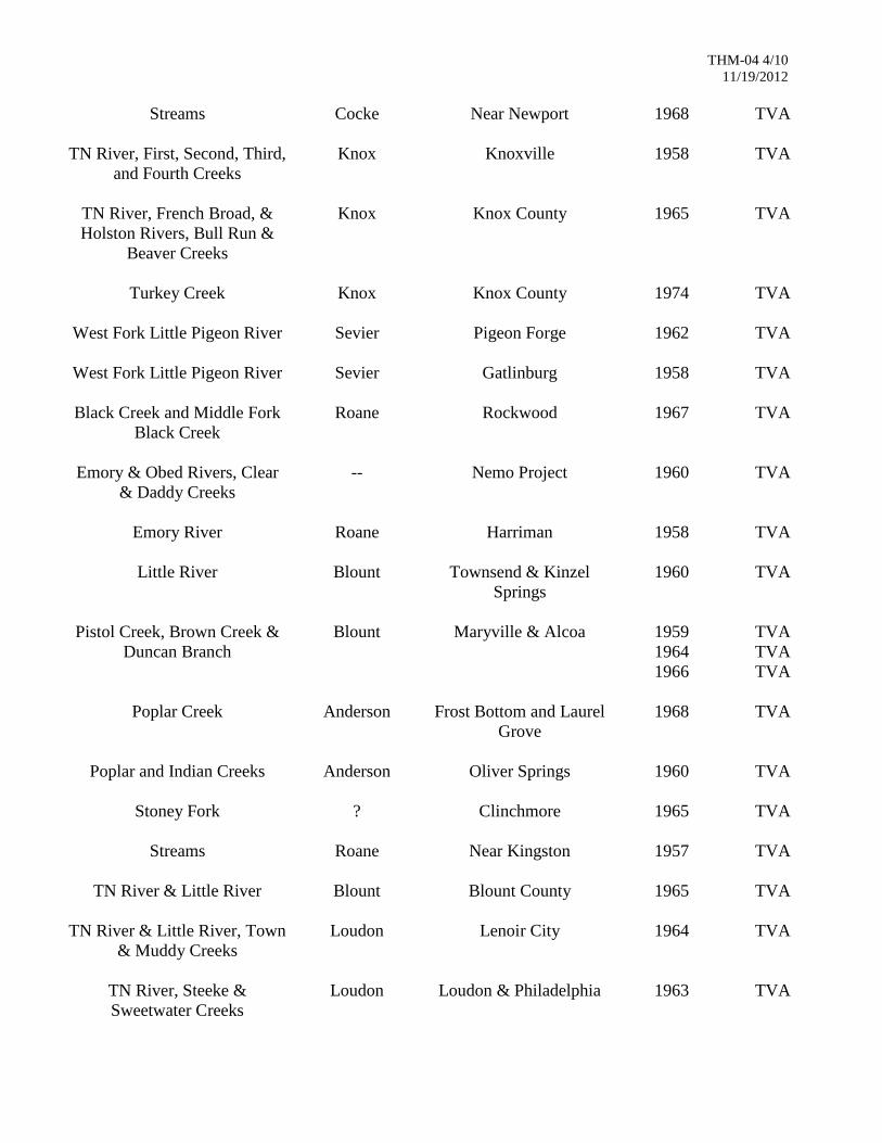
THM-04 4/10
11/19/2012
Streams
Cocke Near Newport
1968 TVA
TN River, First, Second, Third,
and Fourth Creeks
Knox Knoxville
1958 TVA
TN River, French Broad, &
Holston Rivers, Bull Run &
Beaver Creeks
Knox Knox County
1965 TVA
Turkey Creek
Knox Knox County
1974 TVA
West Fork Little Pigeon River
Sevier Pigeon Forge
1962 TVA
West Fork Little Pigeon River
Sevier Gatlinburg
1958 TVA
Black Creek and Middle Fork
Black Creek
Roane Rockwood
1967 TVA
Emory & Obed Rivers, Clear
& Daddy Creeks
-- Nemo Project
1960 TVA
Emory River
Roane Harriman
1958 TVA
Little River
Blount Townsend & Kinzel
Springs
1960 TVA
Pistol Creek, Brown Creek &
Duncan Branch
Blount Maryville & Alcoa
1959
1964
1966
TVA
TVA
TVA
Poplar Creek
Anderson Frost Bottom and Laurel
Grove
1968 TVA
Poplar and Indian Creeks
Anderson Oliver Springs
1960 TVA
Stoney Fork
? Clinchmore
1965 TVA
Streams
Roane Near Kingston
1957 TVA
TN River & Little River
Blount Blount County
1965 TVA
TN River & Little River, Town
& Muddy Creeks
Loudon Lenoir City
1964 TVA
TN River, Steeke &
Sweetwater Creeks
Loudon Loudon & Philadelphia
1963 TVA
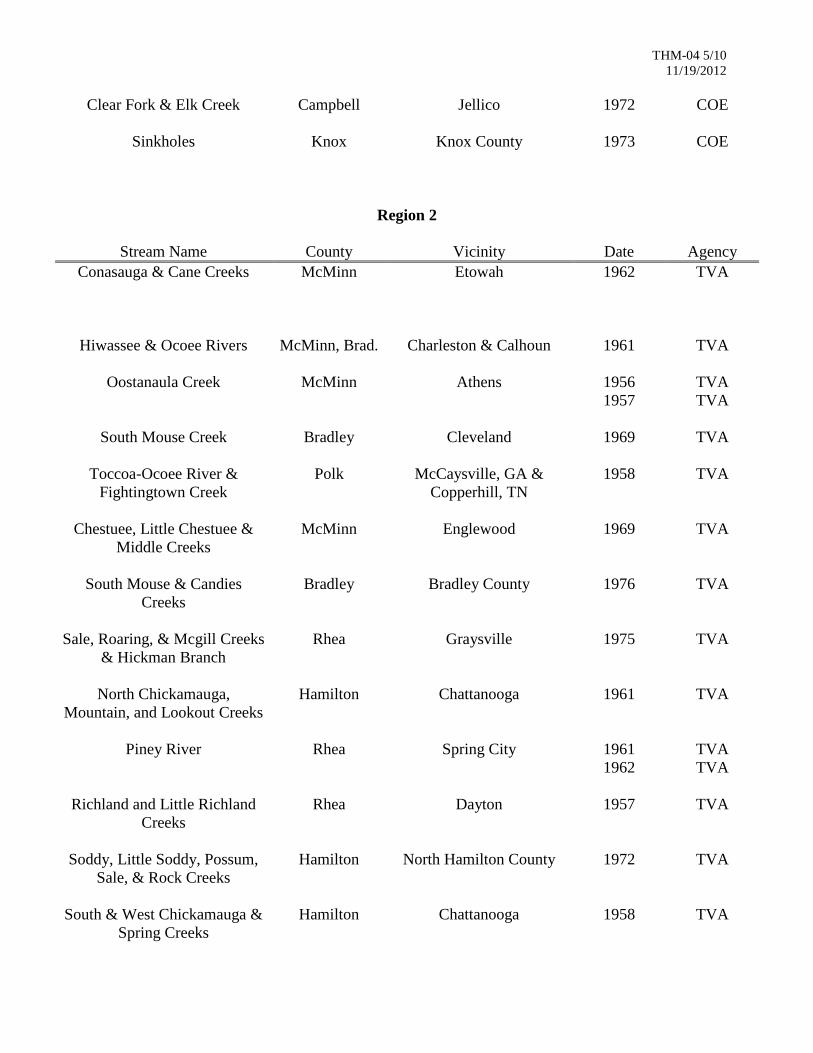
THM-04 5/10
11/19/2012
Clear Fork & Elk Creek
Campbell Jellico
1972 COE
Sinkholes
Knox Knox County
1973 COE
Region 2
Stream Name County Vicinity Date Agency
Conasauga & Cane Creeks
McMinn Etowah
1962 TVA
Hiwassee & Ocoee Rivers
McMinn, Brad. Charleston & Calhoun 1961 TVA
Oostanaula Creek
McMinn Athens 1956
1957
TVA
TVA
South Mouse Creek
Bradley Cleveland
1969 TVA
Toccoa-Ocoee River &
Fightingtown Creek
Polk McCaysville, GA &
Copperhill, TN
1958 TVA
Chestuee, Little Chestuee &
Middle Creeks
McMinn Englewood
1969 TVA
South Mouse & Candies
Creeks
Bradley Bradley County
1976 TVA
Sale, Roaring, & Mcgill Creeks
& Hickman Branch
Rhea Graysville
1975 TVA
North Chickamauga,
Mountain, and Lookout Creeks
Hamilton Chattanooga
1961 TVA
Piney River
Rhea Spring City
1961
1962
TVA
TVA
Richland and Little Richland
Creeks
Rhea Dayton
1957 TVA
Soddy, Little Soddy, Possum,
Sale, & Rock Creeks
Hamilton North Hamilton County
1972 TVA
South & West Chickamauga &
Spring Creeks
Hamilton Chattanooga
1958 TVA
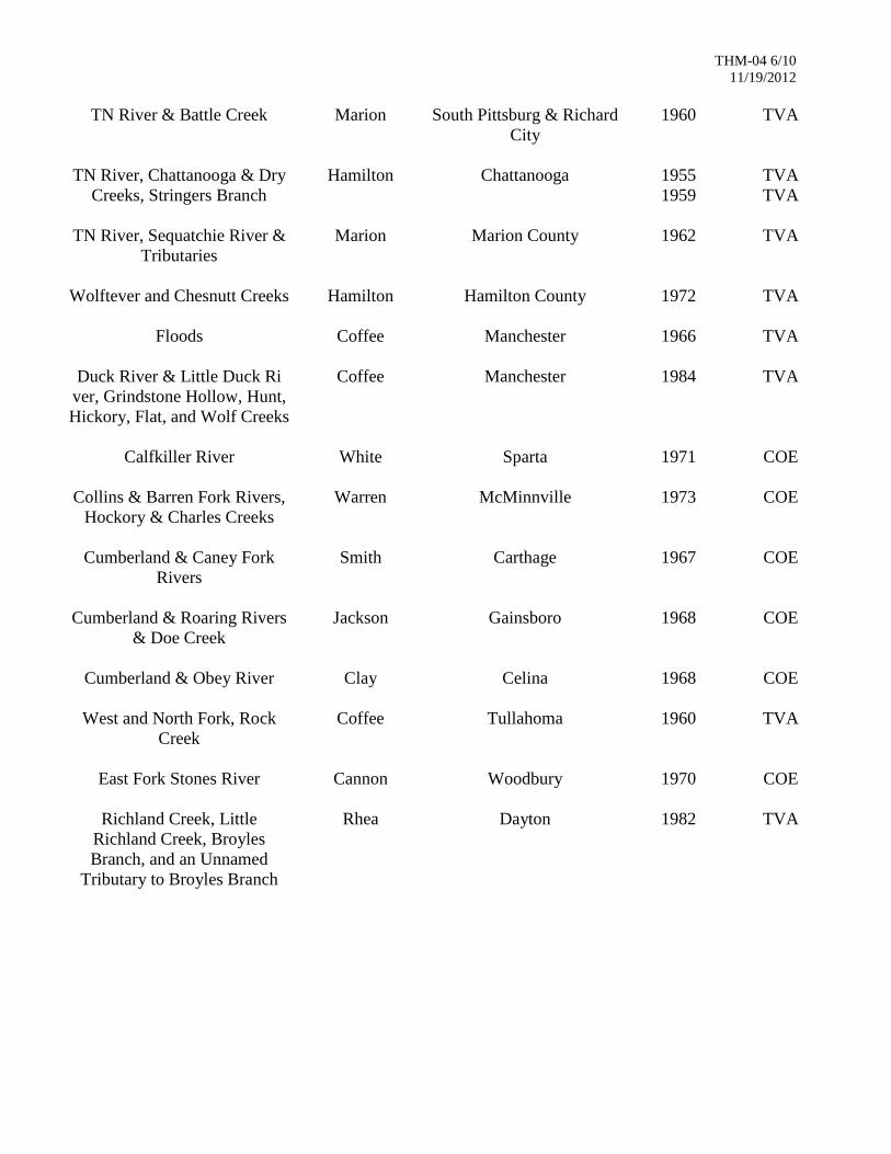
THM-04 6/10
11/19/2012
TN River & Battle Creek
Marion South Pittsburg & Richard
City
1960 TVA
TN River, Chattanooga & Dry
Creeks, Stringers Branch
Hamilton Chattanooga
1955
1959
TVA
TVA
TN River, Sequatchie River &
Tributaries
Marion Marion County
1962 TVA
Wolftever and Chesnutt Creeks
Hamilton Hamilton County
1972 TVA
Floods
Coffee Manchester
1966 TVA
Duck River & Little Duck Ri
ver, Grindstone Hollow, Hunt,
Hickory, Flat, and Wolf Creeks
Coffee Manchester
1984 TVA
Calfkiller River
White Sparta
1971 COE
Collins & Barren Fork Rivers,
Hockory & Charles Creeks
Warren McMinnville
1973 COE
Cumberland & Caney Fork
Rivers
Smith Carthage
1967 COE
Cumberland & Roaring Rivers
& Doe Creek
Jackson Gainsboro
1968 COE
Cumberland & Obey River
Clay Celina
1968 COE
West and North Fork, Rock
Creek
Coffee Tullahoma
1960 TVA
East Fork Stones River
Cannon Woodbury
1970 COE
Richland Creek, Little
Richland Creek, Broyles
Branch, and an Unnamed
Tributary to Broyles Branch
Rhea Dayton
1982 TVA
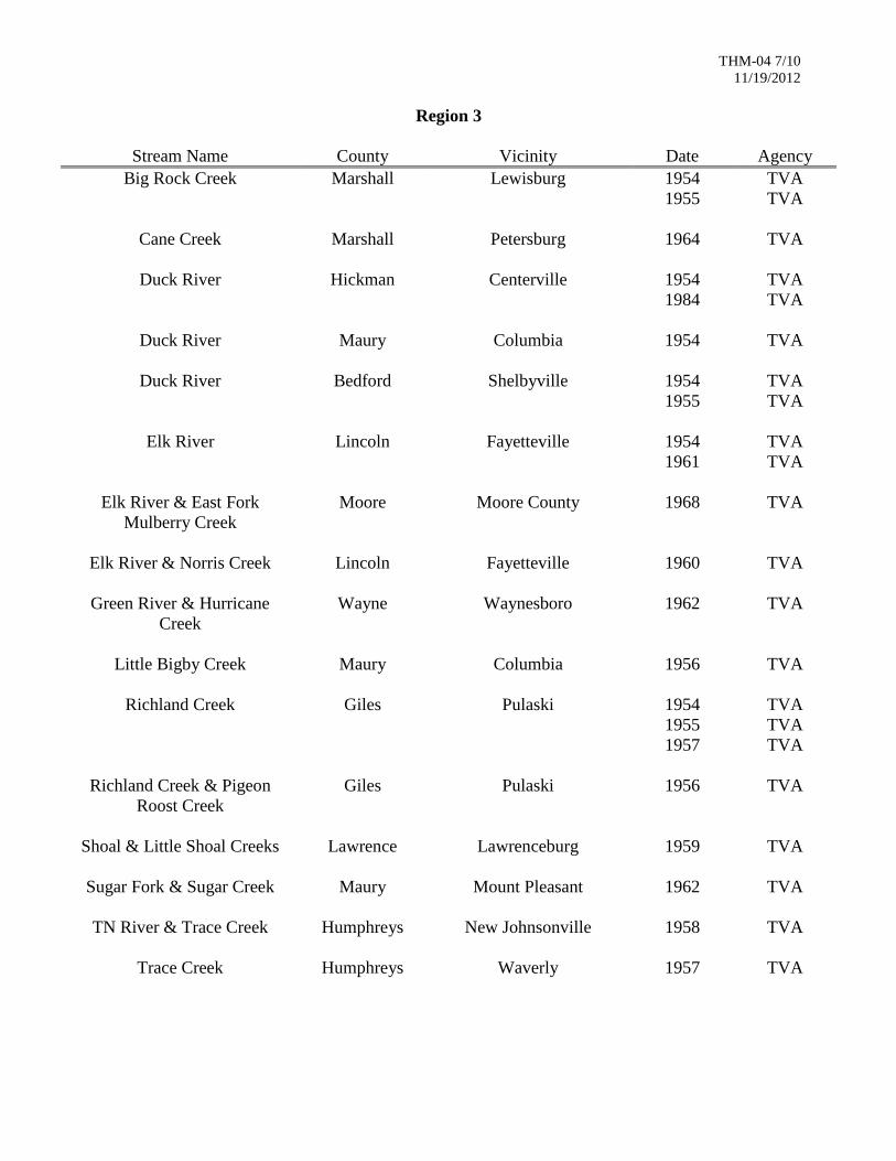
THM-04 7/10
11/19/2012
Region 3
Stream Name County Vicinity Date Agency
Big Rock Creek
Marshall Lewisburg
1954
1955
TVA
TVA
Cane Creek
Marshall Petersburg
1964 TVA
Duck River
Hickman Centerville
1954
1984
TVA
TVA
Duck River
Maury Columbia
1954
TVA
Duck River
Bedford Shelbyville
1954
1955
TVA
TVA
Elk River
Lincoln Fayetteville
1954
1961
TVA
TVA
Elk River & East Fork
Mulberry Creek
Moore Moore County
1968 TVA
Elk River & Norris Creek
Lincoln Fayetteville
1960 TVA
Green River & Hurricane
Creek
Wayne Waynesboro
1962 TVA
Little Bigby Creek
Maury Columbia
1956 TVA
Richland Creek
Giles Pulaski
1954
1955
1957
TVA
TVA
TVA
Richland Creek & Pigeon
Roost Creek
Giles Pulaski
1956 TVA
Shoal & Little Shoal Creeks
Lawrence Lawrenceburg
1959 TVA
Sugar Fork & Sugar Creek
Maury Mount Pleasant
1962 TVA
TN River & Trace Creek
Humphreys New Johnsonville
1958 TVA
Trace Creek
Humphreys Waverly
1957 TVA
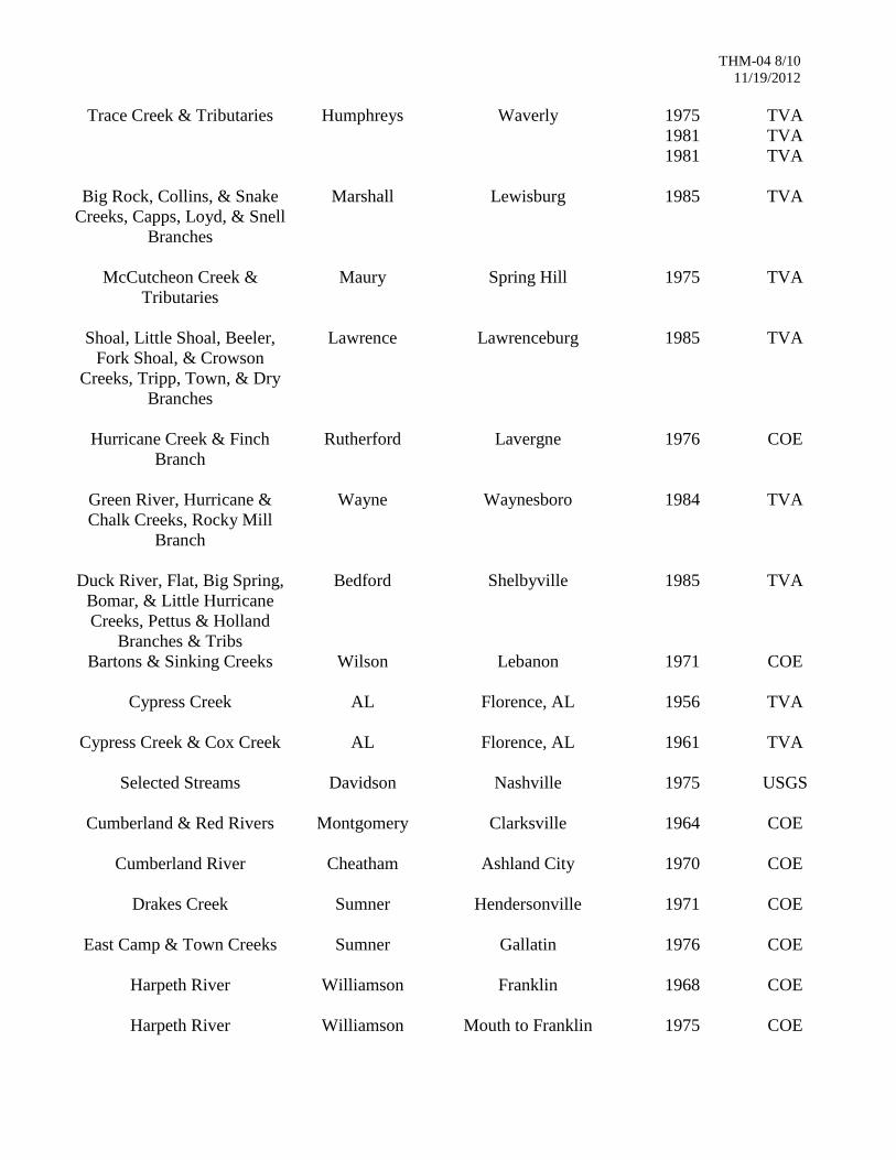
THM-04 8/10
11/19/2012
Trace Creek & Tributaries
Humphreys Waverly 1975
1981
1981
TVA
TVA
TVA
Big Rock, Collins, & Snake
Creeks, Capps, Loyd, & Snell
Branches
Marshall Lewisburg
1985 TVA
McCutcheon Creek &
Tributaries
Maury Spring Hill 1975 TVA
Shoal, Little Shoal, Beeler,
Fork Shoal, & Crowson
Creeks, Tripp, Town, & Dry
Branches
Lawrence Lawrenceburg
1985 TVA
Hurricane Creek & Finch
Branch
Rutherford Lavergne
1976 COE
Green River, Hurricane &
Chalk Creeks, Rocky Mill
Branch
Wayne Waynesboro
1984 TVA
Duck River, Flat, Big Spring,
Bomar, & Little Hurricane
Creeks, Pettus & Holland
Branches & Tribs
Bedford Shelbyville
1985 TVA
Bartons & Sinking Creeks
Wilson Lebanon
1971 COE
Cypress Creek
AL Florence, AL
1956 TVA
Cypress Creek & Cox Creek
AL Florence, AL
1961 TVA
Selected Streams
Davidson Nashville
1975 USGS
Cumberland & Red Rivers
Montgomery Clarksville
1964 COE
Cumberland River
Cheatham Ashland City
1970 COE
Drakes Creek
Sumner Hendersonville
1971 COE
East Camp & Town Creeks
Sumner Gallatin
1976 COE
Harpeth River
Williamson Franklin
1968 COE
Harpeth River
Williamson Mouth to Franklin
1975 COE
THM-04 9/10
11/19/2012
Little Goose Creek
Trousdale Hartsville
1975 COE
Little Harpeth River
Williamson Williamson County
1968 COE
Mill & Seven Mile Creeks
Davidson Nashville
1973 COE
Sulpher Fork
Robertson Springfield
1972 COE
Wells Creek & Tribs
Houston Erin
1973 COE
West Fork Stones River, Lytle
& Sinking Creeks
Rutherford Murfreesboro
1966 COE
East Fork Mulberry Creek &
Price Branch
Moore Near Lynchburg
1986 TVA
Stewerts Creek, & Harts
Branch
Rutherford Smyrna
1976 COE
Region 4
Stream Name County Vicinity Date Agency
Beech River, Wolf & Owl
Creeks, Brazil, Onemile
Branches & a Branch
Henderson Lexington 1985 TVA
Bailey Fork, Town & Jones
Bend Creeks, Mcgowan
Branch
Henry Paris 1969 TVA
Beaver Creek & Tribs
Carroll Huntingdon
1971 COE
Big Creek
Shelby Millington 1974
1981
COE
COE
Cypress, Cane, Charlie, and
Burnside Creeks
Benton Camden
1961 TVA
Forked Deer Rivers & Lewis
Creek
Dyer Dyersburg
1968 COE
Hatchie River, Pleasant Run &
Spring Creeks
Hardeman Bolivar
1970 COE

THM-04 10/10
11/19/2012
Loosahatchie River
Shelby Shelby County
1970 COE
Middle Fork Forked Deer
River & Tribs
Gibson Humboldt
1970 COE
Nonconnah Creek
Shelby Shelby County
1974 COE
Nonconnah Creek
Shelby Shelby County
1987
1990
COE-GDM
COE-GDM
North Fork Forked Deer River
& Cane Creek
Gibson Trenton
1962 COE
North Fork Obion River,
Hoosier & Grove Creeks
Obion Union City
1968 COE
South Fork Forked Deer River
& Sugar Creek
Chester Henderson
1968 COE
South Fork Forked Deer River,
North Fork Drainage Canal,
Bond Creek
Madison Jackson 1967 COE
Sugar Creek & Little Nixon
Creek
Haywood Brownsville 1973 COE
Harrington Creek
Madison Bartlett
1975 COE
Grays & Marys Creeks
Shelby Shelby County
1970 COE
Rutherford Fork Obion River
Gibson Milan
1974 COE
Cane Creek & Tribs
Lauderdale Ripley
1977 COE
Mud Creek & Laterals A, B, C,
& D
Weakley Dresden
1976 COE
Wolf & Loosahatchie Rivers
Shelby Shelby County
1971 COE
Harris Fork Creek & South
Fulton Branch
Obion South Fulton
1971 COE
Harris Fork Creek Obion South Fulton 1983 COE-GDM

THM-05 1/3
11/16/12
TENNESSEE HYDRAULICS MEMORANDUM - 05
Approval of Bridge Plans by Outside Agencies
Distribution: Office, Consultants
Preliminary and/or final bridge plans must be submitted to various agencies for review. The degree of review varies
with each agency, depending on their project involvement and legal responsibilities. Some reviews are only for the
purpose of coordinating plans, while others are based on the legal authority of the agency to review and dictate design
considerations.
The various departments and agencies involved in T DOT work are listed below with a brief description of their review
responsibility. Submittal to these agencies for work prepared by consultants shall be through the T. DOT
Environmental Division, unless instructed differently.
1 - Design Division
Prior to submitting preliminary plans to the FHWA (see 4 below) or commencing final design on other work, a
preliminary layout shall be submitted to the appropriate Engineering Manager - Design Division, to insure
agreement with the design criteria established for the roadway. .
2 - Environmental Division
The Environmental Division is responsible for obtaining approval for construction of TDOT projects from all
environmental regulatory agencies including the Tennessee Valley Authority, Tennessee Department of
Environment and Conservation, Tennessee Wildlife Resources Agency, and the U.S. Army Corps of Engineers.
The Environmental Division will also coordinate with commenting agencies such as the U.S. Fish and Wildlife
Service, Environmental Protection Agency, National Park Service, and others as required. The Environmental
Division should be provided with roadway plans and bridge preliminary layouts when available for permit
assessment and technical studies.
3 - Utilities
All bridges may be used to accommodate utility lines provided they are not injurious to the structure, do not
restrict hydraulic capacity or are not visible to the normal view of the public. Proposals regarding utilities are
submitted through the Manager - Utilities Section. See Structures Memorandum 036.
4 - Railroads
Four (4) sets of prints of the preliminary layout and related roadway plans for all structures involving railroads
must be submitted through the Manager - Utilities Section to the railroad for approval. The preliminary layout
shall be prepared in accordance with Structures Memorandum 010.
5 – Federal Highway Administration (FHWA)
Preliminary plans for the following structures shall be submitted to FHWA for approval:
a) Bridges that are a part of an Interstate Highway Project.
b) Bridges in Non-Interstate Highway Projects that cross the Interstate Highway System (for clearance approval
only).
The Division office of FHWA has requested to have the opportunity to review bridges on and over National
Highway System (NHS) routes and any bridges receiving Federal Funds, with an estimated cost of $10,000,000
or more. (The $10,000,000 cost applies to Single structures or dual bridge crossings).
THM-05 2/3
11/16/12
The submittal should consist of one print of bridge preliminaries and one print of roadway plans with: Title Sheet,
Typical Cross Sections, pertinent R.O.W. and Plan & Profile Sheets showing bridge sites involved.
6 - Tennessee Valley Authority (TVA)
Navigational clearance requirements shall be coordinated with TVA and the Hydraulic Design Section. In some
cases approval of plans will be necessary under the authority of Section 26a of the TVA Act of 1933. Permit
submittal requirements will be provided by the Environmental Division. Impacts to TVA property or structures
will be coordinated by the Right of Way Division.
Projects requiring placement of fill in TVA reservoirs in excess of the TVA reservoir fill limits shall be
coordinated by the Hydraulic Design Section with the Environmental Division Permits Section. The Hydraulic
Design Section will create a fill offset plan according to the standard template and coordinate it with TVA River
Operations prior to supplying it to the Environmental Division Permits Section for the permit application.
7 - U.S. Army Corps of Engineers (USACE)
Construction on waterways deemed navigable by the USACE requires a Section 10 permit and shall be
coordinated during bridge design by the Hydraulic Design Section with the Environmental Division Permits
Section. Construction in any waters of the United States requires approval of the USACE under the authority of
the Clean Water Act, Section 404. Section 404 requirements will be supplied by the Environmental Division.
Projects requiring placement of any fill in USACE reservoirs shall be coordinated by the Hydraulic Design
Section during the design process with the Environmental Division Permits Section, Design Division Manager,
Region Construction Office, USACE Floodplain Manager, and the appropriate USACE Reservoir Manager. The
Hydraulic Design Section will coordinate a fill offset plan to best meet the requirements of each of the above
listed offices, so the Design Division Manager can develop the details to appear in the final construction plans.
The plans will be coordinated with the USACE prior to supplying it to the Environmental Division Permits
Section for the permit application. Flowage easement impacts will be coordinated with the Right Of Way
Division.
8 - U. S. Coast Guard (USCG)
The Hydraulic Design Section will be responsible for coordinating applications to the Eighth Coast Guard District
for Permits for new bridge construction over navigable waterways of the United States as identified in
"Applications for Coast Guard Bridge Permits" published by the Eighth Coast Guard District, St. Louis, MO.
Applications will be for commercially navigable waterways only. The Hydraulic Design Section will be
responsible for distributing the USCG bridge permits as well. Once the bridge is under construction the contractor
will be responsible for amending the permit as needed and supplying the USCG with schedules of all activities
and equipment in the navigable waterway before the activities begin. TVA and the USACE may have navigation
requirements for other waterways and tributaries that must be followed but will be coordinated with each of those
agencies during the bridge design and permitting processes. Most bridge repair projects are the contractor’s
responsibility to contact the USCG and coordinate activities and equipment as required.
9 – Federal Emergency Management Agency (FEMA)
The Hydraulic Design Section will be responsible for coordination with FEMA and the appropriate local
government agencies when bridge or roadway projects impact streams with detailed FEMA Flood Insurance
Studies. Coordination with the Design Division will be done to minimize or avoid flood plain and/or floodway
impacts. No rise certifications or CLOMR applications will be provided when required with copies to the
Environmental Division Permits Section.

THM-05 3/3
11/16/12
10 - U. S. Natural Resource Conservation Service (NRCS)
This agency will be contacted, where stream crossings are involved with completed or active NRCS stream
restoration or stream bank stabilization projects, for information purposes and/or co-ordination of design. The
Division of Structures will maintain liaison with the NRCS according to instructions given in Structures
Memorandum 024.

THM-06 1/3
11/16/12
TENNESSEE HYDRAULICS MEMORANDUM - 06
Improved Inlets and Energy Dissipaters for Culverts and Box or Slab Bridges
Distribution: Office, Consultants
Culvert capacity is based on either culvert entrance conditions (inlet control) or barrel resistance (outlet control). For
inlet control, the culvert's capacity is based only on entrance configuration and headwater depth, in which case the
culvert barrel could handle more flow than the inlet. Therefore, for culverts operating in inlet control the use of
improved inlets would maximize the barrel capacity.
Culverts in inlet control usually lie on steep slopes and flow only partly full. Entrance improvements can result in a
reduction in barrel size and a proportional reduction in project cost. The amount of reduction depends on site
conditions and engineering judgment regarding the dependability of flood estimates and limiting headwater elevations,
as well as outlet velocities to avoid damages.
Improved inlets may be constructed on existing culverts with inadequate capacity. This may avoid the replacement of
the entire structure or the addition of a new parallel culvert.
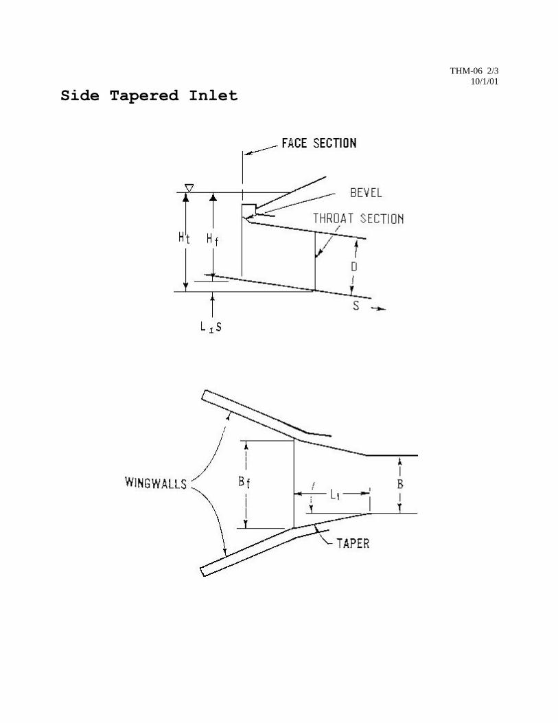
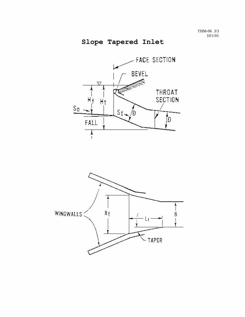
Three types of inlet improvements should be considered. These are bevel-edged, side-tapered and slope-tapered inlets.
Bevel-edged inlets are utilized on all TDOT standard culvert drawings.
Side-tapered inlets have an enlarged face area with tapering sidewalls to transition to the culvert barrel (see Figure 1).
They can provide as much as 40 percent increase in flow capacity over that of conventional inlets. Slope-tapered inlets
provide a depression or fall in conjunction with a taper at the inlet (see Figure 2). In some cases they can provide over
100 percent greater capacity than a conventional inlet. Cost of excavation and sediment potential are prime
considerations for these designs.
Culvert and inlet designs should be based on procedures outlined in F.H.W.A. publications "Hydraulic Design of
Highway Culverts”, HDS-5 and "Hydraulic Design of Improved Inlets for Culverts”, HEC-13.
Pre-cast concrete alternatives may be used with approval of the Hydraulic Design Section or Design Division Manager
as required by the hydraulic design responsibility of the crossing.
Energy dissipaters may be required for culverts with high outlet velocities in excess of 15 fps (4.6 m/s). There are many
types of energy dissipaters ranging from riprap basins to large concrete structures with complicated geometries and
hydraulics. Two main classes are internal and external dissipaters. Standard drawings are available for the tumbling
flow internal dissipater and the USBR Type VI external dissipater from the Structures Division and a standard riprap
basin drawing is available from the Design Division. Drawings are available for different dissipaters that have been
constructed on various projects if needed for reference.
All energy dissipater design should be done according to “Hydraulic Design of Energy Dissipaters for Culverts and
Channels”, HEC-14.
THM-06 2/3
10/1/01
Side Tapered Inlet
THM-06 3/3
10/1/01
Slope Tapered Inlet
THM-07 1/2 5/3/13
TENNESSEE HYDRAULICS MEMORANDUM - 07 Drainage of Bridge Decks Distribution: Office, Consultants General Drainage Requirements Bridge Deck Drains and End of Bridge Drains shall not be used unless necessary to prevent flooding of the traveled way or to prevent erosion around abutment wingwalls. The Rational Method shall be used for computing runoff with rainfall intensity for the site selected from the National Weather Service Rainfall - Frequency Atlas 14 (available on NWS website) for the site using 5 minute duration (minimum). The Design Storm will be a 10-year frequency storm, except that a 50-year frequency storm shall be used for bridges in which the low point of a sag vertical curve would occur on the bridge or approach pavements. Interstate bridges will have a 50 year design for all cases. The methods described in Hydraulic Engineering Circular No. 21 (HEC 21), Design of Bridge Deck Drainage, published by the Federal Highway Administration (FHWA) shall be utilized in the analysis and design of bridge deck drainage. A modified Manning's equation will be used in the analysis of the triangular flow along the gutter line. Bridges constructed on 0.00 % grades are undesirable and should be avoided. However, cases do arise where a 0.00% grade is required. In these cases the methods described in HEC 21 should be used. Bridge Deck Drains and End of Bridge Drains shall be spaced so that no more than the shoulder area would be flooded during the design storm where possible. At locations with a Design Speed of less than 45 mile/h (70 km/h) and minimum shoulder widths of 2 to 4 feet (0.6 to 1.2 meters), it may be acceptable to allow limited spread into the lane adjacent to the shoulder. In no case will the usable roadway width in the inundated lane be reduced to less than 6 feet (1.8 m). Chapter 4 of the FHWA HEC 22 manual has more detailed suggested minimum design frequency and spread guidelines. Additionally, an open bridge rail (STD-7-1) is desirable in these locations and may negate the need for drainage appurtenances. Where bike lanes are available next to the shoulder, this width may be used for spread since bicycle travel at a design rainfall event would be very unlikely. Bridge Rail Selection Criteria Girder bridges on all systems are to be fitted with the appropriate concrete rail. Three standard designs for bridge rails are available.
• STD-1-1SS: This is the standard reinforced concrete closed parapet rail. • STD-7-1: This is an open concrete post and rail which allows drainage to flow unimpeded off of the
bridge deck. The open rail may not be used on Interstates or primary State Routes. It may be used on local roads or secondary State Routes with a design speed less than 45 miles per hour (70 km per hour). It is best used in situations where flood flow frequently overtops the road, where sight distance considerations prohibit the use of STD-1-1SS, or when roadway geometry prohibits draining the bridge deck with standard deck drains.
• STD-11-1: This is a straight faced concrete parapet with structural tubing. This rail is used on all
bridges with a sidewalk. Use of the STD-7-1 open rail should be carefully considered even at sites that meet the above criteria if there are unusual mitigating factors such as high traffic volume, unusual roadway geometry, or a long drop to natural ground or water feature. The use of any rail other than the three standard rails must be approved by the Director of the Structures Division.
THM-07 2/2 5/3/13
The criteria for the use of Bridge Deck Drains are as follows: At locations where a sag vertical curve occurs on a bridge, flanking inlets will be required in addition to a drain at the sag location. Additionally, where end of bridge drains are required, deck drains may be required so that the end of bridge drains can intercept the required bridge deck drainage (See End of Bridge Drain Requirements). Special consideration will be given to drain spacing on structures with reverse horizontal curves occurring on the bridge. Sufficient drain openings will be provided to minimize "cross flow" onto traffic lanes at super elevation transition areas. In the event deck drains are used, drainage should not be allowed to fall onto bridge piers and girders, railroad beds, roadways or other sensitive features. Additionally, it is undesirable to allow drainage to fall onto abutment berms and roadway shoulders. Berms and bridge slopes are acceptable if class A-1 or larger riprap is present. An under deck collection and discharge system may be required in certain cases. The design of under deck collection and discharge systems shall conform to the methods described in HEC 21. See STD-1-2 for standard parapet openings and standard grate type openings. Parapet openings are the drain of choice due to cost considerations and should be utilized where possible. In cases where grate type openings may be required (e.g., curb & gutter sections, adjacent to median barriers, super elevation cross over sites, special conditions, etc...), the grate opening inlet on STD-1-2 should be used. The grate inlet is considerably more efficient in most cases and may solve excessive spread problems. However the grate type inlet is generally more expensive. Deck drain downspouts should not be used where the downspout will exit the bridge deck outside exterior beam lines of a bridge (i.e. under an overhang). Where grate type deck drains are required outside beam lines, STD-1-2 Grate Inlet Type 1 should be utilized. Where a grate type drain with a downspout is required, the downspout shall terminate 3 inches (0.08 m) below the bottom face of adjacent beam lines. All clearance requirements both horizontal and vertical shall remain in effect. Every attempt possible shall be made to avoid the use of deck drains on structures utilizing Weathering Steel beams. Where deck drains are required, a drain utilizing a downspout shall be required subject to approval by the Director of the Structures Division. Conditions do arise where deck drains detailed in STD-1-2 do not conform to site conditions. In these cases a site specific drain will be developed subject to review by the Director of the Structures Division. The criteria for the use of End of Bridge Drains are as follows: End of Bridge Drains will be required in all cases with the following exceptions;
1.) When using an open type bridgerail (STD-7-1, etc...). 2.) When Rip-Rap is brought up to the edge of shoulder and the discharge around the wing is not
excessive. 3.) In curb and gutter sections where flow cannot exit the roadway and erode fill slopes, End of Bridge
Drains may not be required. If spread requirements can be met, roadway drains should be used instead of End of Bridge Drains. The location of roadway drains should be coordinated with the roadway designer in order to determine if spread requirements can be met.
When End of Bridge Drains are required, the 2 ft X 8 ft 7in (610 mm X 2620 mm) drains are preferred due to cost. The 4 ft X 8 ft 7in (1220 mm X 2620 mm) should be used for wide shoulders when bypass flows are excessive and need to be intercepted and when extra deck drains cannot be added reasonably to minimize those flows for a 2 ft wide EOB drain to work. In no case shall the end of bridge or deck drain grate be used when it may protrude into the traffic lane.

THM-08 1/3
11/16/12
TENNESSEE HYDRAULICS MEMORANDUM - 08
Scour and Fill at Bridge Waterways
Distribution: Office, Consultants
General
All structures should be evaluated for scour potential. A scour analysis will be required for all bridges and any other
crossing without footings or piles on competent rock. Inlet and outlet protection for standard box and slab bridges will
be evaluated during hydraulic design and treated according to guidance provided in the TDOT Drainage Manual. The
Federal Highway Administration's Hydraulic Engineering Circular No. 18 (HEC-18) entitled "Evaluating Scour at
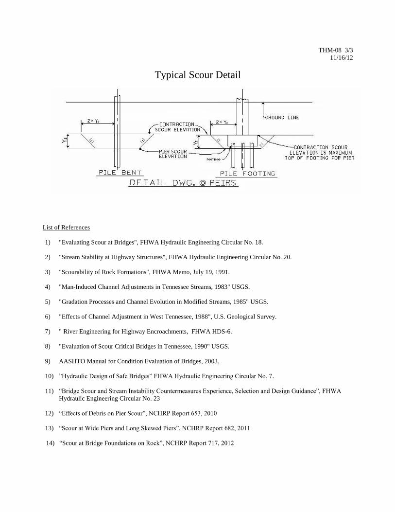
Bridges" will be used to determine design scour elevations for all girder bridge substructures. See the typical scour
detail below for a sketch on how to show scour on the profile view of the bridge layout sheets.
Channel migration in meandering streams, bank failure studies, debris assessments, and effects of aggradation or
degradation on side slopes are other key factors that should be determined using U.S. Geologic Survey (USGS)
techniques provided in reference materials or latest FHWA or NCHRP guidance as appropriate.
Procedures/Guidelines
Predicted scour depths will be calculated at a minimum for the 100 and 500 year flood flows and additionally for the
road overtopping flow, if applicable. For existing crossings, predicted scour depths will be calculated for the 2, 10, 50,
100, and 500 year flood flows at a minimum. The worst of these predicted depths will be sketched onto the profile view
of the bridge layout similar to the typical scour detail below and be used for foundation design or scour countermeasure
protection design. In the case of multiple bridge openings, the predicted scour depths should be calculated for all flood
profiles analyzed at all the crossings to determine if a replacement bridge will worsen the scour condition of any
remaining existing bridges and countermeasures should be designed accordingly.
Bank stability analysis will be included in TDOT soils and foundation reports. Scour values calculated during the
preliminary layout design, prior to receipt of soil borings, are considered tentative and must be confirmed using TDOT
approved geotechnical reports prior to development of final bridge plans.
Top of footings for channel piers will be placed at the predicted scour elevation or a minimum of 6 feet (1.8 m) below
the stream bed elevation, considering degradation, if applicable. Footings for overbank piers adjacent to channel banks
will be set similar to channel piers to account for possible bank slope failure, channel widening, or lateral migration of
the channel. Footings for overbank piers not adjacent to channel banks will be placed at the predicted overbank scour
elevation or a minimum of 6 feet (1.8 m) below the local ground elevation whichever is less.
Pile penetration of at least 15 feet (4.5 m) is to be provided in all cases below the computed scour elevations for the
combination of all components of scour for the flood that produces the greatest amount of scour up to a 500 year flow.
Spread footings on soil or erodible rock shall be placed below the computed scour line. Sufficient subsurface
investigations will be made for shallow foundations to identify weathering and rock discontinuities in establishing
footing elevations. NCHRP studies are available to predict elevations for scour at bridge foundations on rock.
All countermeasures to protect the structure against effects of scour are to be developed during the hydraulic study
phase for each project. Typical designs and remedies include rip-rap and gabion basket or mattress slope protection,
retaining walls and cut-off walls, deep foundations, flood relief flow over the approaches, overflow bridges, excavation
under bridges and guide banks. Other countermeasures can be found in FHWA Hydraulic Engineering Circulars and
NCHRP research reports.
The USGS has completed a study to identify scour potential for streams in Tennessee and scour critical bridge
locations. This report may be reviewed for the site under study for use as historical bridge information. The report is
on file in the Hydraulic Design Section of the TDOT Structures Division.

THM-08 2/3
11/16/12
The FHWA has published phase I and II of the Bottomless Culvert Scour Study on scour prediction for three sided pre-
cast and metal arch structures. The preferred foundation design for these structures is to have footings placed on
competent rock or provide a concrete bottom and cut off wall similar to standard box bridges. If an alternate design of
piles below the footing or a footing placed on erodible material with riprap or other non-permanent scour protection is
desired, then a predicted scour depth and riprap sizing analysis using the procedures provided by the FHWA must be
used for the foundation design and approved by the Hydraulics Section.
THM-08 3/3
11/16/12
Typical Scour Detail
List of References
1) "Evaluating Scour at Bridges", FHWA Hydraulic Engineering Circular No. 18.
2) "Stream Stability at Highway Structures", FHWA Hydraulic Engineering Circular No. 20.
3) "Scourability of Rock Formations", FHWA Memo, July 19, 1991.
4) "Man-Induced Channel Adjustments in Tennessee Streams, 1983" USGS.
5) "Gradation Processes and Channel Evolution in Modified Streams, 1985" USGS.
6) "Effects of Channel Adjustment in West Tennessee, 1988", U.S. Geological Survey.
7) " River Engineering for Highway Encroachments, FHWA HDS-6.
8) "Evaluation of Scour Critical Bridges in Tennessee, 1990" USGS.
9) AASHTO Manual for Condition Evaluation of Bridges, 2003.
10) ”Hydraulic Design of Safe Bridges” FHWA Hydraulic Engineering Circular No. 7.
11) “Bridge Scour and Stream Instability Countermeasures Experience, Selection and Design Guidance”, FHWA
Hydraulic Engineering Circular No. 23
12) “Effects of Debris on Pier Scour”, NCHRP Report 653, 2010
13) “Scour at Wide Piers and Long Skewed Piers”, NCHRP Report 682, 2011
14) “Scour at Bridge Foundations on Rock”, NCHRP Report 717, 2012

THM-09 1/4
10/8/12
TENNESSEE HYDRAULICS MEMORANDUM - 09
Rip-Rap For Bridge Waterways, Open Channels And Grade Crossings
Distribution: Office, Consultants
PART I - Rip-Rap for Bridge Waterways and Open Channels
General Guidelines
Slope stabilization should be used at all structures over streams where earth fill material is placed below the 500 year
flood stage or on channels where the vegetation has been removed such as occurs at a channel widening or relocation.
This also applies to box bridge locations in select cases.
See the sketch below for slope protection at bridge abutments. The rip-rap should be carried along the roadway
embankment beyond the abutment wingwalls for 25 feet (7 m). This Rip-Rap sketch is also valid for bank protection.
Figure 1: Rip Rap Sketch For Bridge And Bank Slopes
Class of Rip-Rap “B” at right angle
to abut.
“T”
Rip-Rap
thickness
Assumed d50
for design
General
velocity range
for use
A 4 ft (1.2 m) 1.5 ft (0.45 m) 0.75 ft (0.23 m) 0-5 fps
B 6 ft(1.8 m) 2.5 ft (0.75 m) 1.25 ft (0.38 m) 5-10 fps
C 8 ft (2.4 m) 3.5 ft (1.10 m) 1.75 ft (0.53 m) 10-15 fps

THM-09 2/4
10/8/12
Rip-rap protection may be needed to protect undisturbed earth if velocities through a structure are increased enough to
require bank or channel protection more substantial than could be resisted by the natural conditions.
Formulas for calculating rip-rap stone size, thickness requirements, need for filter blanket and safety factor can be
found in Chapter 4 of HEC-23, “Bridge Scour and Stream Instability Countermeasures”, Reference 10.
Most accepted methods for calculating rip-rap stone size give formulas for the D50 stone size. The term D50 is defined
as the sieve diameter of the rock for which 50 percent of the material by weight is finer. The maximum stone size for a
specific design has a diameter twice that of the D50. The minimum layer thickness is equal to the maximum stone size
diameter. If the rip-rap is expected to be subjected to strong wave action, the minimum thickness should be increased
by 50 percent.
Design Alternatives
Rip-rap for bridge waterway openings and open channels shall be designed and selected on a project by project basis.
The rip-rap specified shall be either Machined Rip-Rap (Class A-1), Machined Rip-Rap (Class A-2 with hand placed
rubble stone alternate), Machined Rip-Rap (Class B), Machined Rip-Rap (Class C) or Rubble Stone Rip-Rap (plain).
All machined rip-rap and rubble stone rip-rap shall be in accordance with Section 709 of the Standard
Specifications except as modified by Special Provision 709.
Rubble Stone Rip-Rap
When Rubble Stone Rip-Rap is called for specifically on the plans (i.e., it is not an alternate to Machined Rip-Rap,
Class A-2), specify the thickness if the thickness is other than 12 inches (0.3 m) and eliminate any reference to Special
Provision 709.
Filter Blanket
A filter blanket may be required to prevent the fines from the embankment from being drawn out through the voids in
the rip-rap stone, as occurs with fill material having a high sand content. The filter blanket may be either crushed
stone, gravel or an approved manufactured filter cloth, or gravel with filter cloth, if embankment material is extremely
fine grained. If a filter cloth is used, construction procedures shall be utilized which ill insure that the cloth is not
damaged during placement of the rip-rap stone. If a crushed stone filter blanket is used, the thickness of the layer of
stone shall be 4 to 6 inches (0.10 to 0.15 m) and the size shall be specified on the plans. The filter blanket will be
included in the rip-rap bid item with the rip-rap quantity increased by the thickness of the filter blanket.
Measurement and Payment
If rip-rap is required specifically for protection of bridge substructures or fills, the rip-rap quantities shall be included
under bridge pay items. If rip-rap is required to protect roadway slopes or channel improvement, it will be bid and paid
for under roadway items. Measurement and payment shall be in accordance with Section 709 of the Standard
Specifications except as modified by Special Provision 709.
Notes For Plans
Machined Rip-Rap shall be Class _____ in accordance with Special Provision 709 of the standard
specifications and shall be paid for as a roadway item.
Rubble Stone Rip-Rap shall be hand placed in accordance with Subsection 709.06 of the Standard
Specifications and shall be paid for as a roadway item.
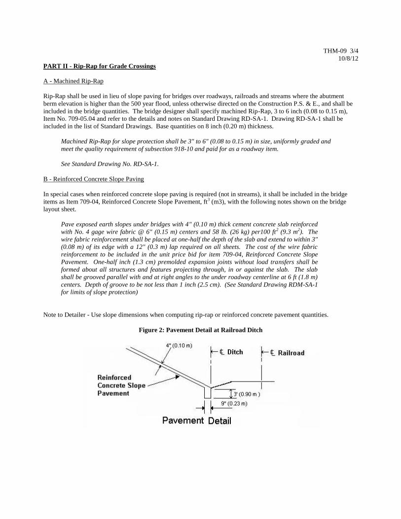
THM-09 3/4
10/8/12
PART II - Rip-Rap for Grade Crossings
A - Machined Rip-Rap
Rip-Rap shall be used in lieu of slope paving for bridges over roadways, railroads and streams where the abutment
berm elevation is higher than the 500 year flood, unless otherwise directed on the Construction P.S. & E., and shall be
included in the bridge quantities. The bridge designer shall specify machined Rip-Rap, 3 to 6 inch (0.08 to 0.15 m),
Item No. 709-05.04 and refer to the details and notes on Standard Drawing RD-SA-1. Drawing RD-SA-1 shall be
included in the list of Standard Drawings. Base quantities on 8 inch (0.20 m) thickness.
Machined Rip-Rap for slope protection shall be 3" to 6" (0.08 to 0.15 m) in size, uniformly graded and
meet the quality requirement of subsection 918-10 and paid for as a roadway item.
See Standard Drawing No. RD-SA-1.
B - Reinforced Concrete Slope Paving
In special cases when reinforced concrete slope paving is required (not in streams), it shall be included in the bridge
items as Item 709-04, Reinforced Concrete Slope Pavement, ft3 (m3), with the following notes shown on the bridge
layout sheet.
Pave exposed earth slopes under bridges with 4" (0.10 m) thick cement concrete slab reinforced
with No. 4 gage wire fabric @ 6" (0.15 m) centers and 58 lb. (26 kg) per100 ft2 (9.3 m
2). The
wire fabric reinforcement shall be placed at one-half the depth of the slab and extend to within 3"
(0.08 m) of its edge with a 12" (0.3 m) lap required on all sheets. The cost of the wire fabric
reinforcement to be included in the unit price bid for item 709-04, Reinforced Concrete Slope
Pavement. One-half inch (1.3 cm) premolded expansion joints without load transfers shall be
formed about all structures and features projecting through, in or against the slab. The slab
shall be grooved parallel with and at right angles to the under roadway centerline at 6 ft (1.8 m)
centers. Depth of groove to be not less than 1 inch (2.5 cm). (See Standard Drawing RDM-SA-1
for limits of slope protection)
Note to Detailer - Use slope dimensions when computing rip-rap or reinforced concrete pavement quantities.
Figure 2: Pavement Detail at Railroad Ditch

THM-09 4/4
10/8/12
List of References
1. HDS-6, “River Engineering for Highway Encroachments”, FHWA .
2. HEC-16, Addendum to "Highways in the River Environment", FHWA.
3. HEC-15, Design of Stable Channels with Flexible Linings, FHWA.
4. Tentative Design Procedure for Rip-Rap Lined Channels, Highway Research Board 1970.
5. Highway Drainage Guidelines, AASHTO.
6. HEC-11, ”Design of Riprap Revetment”, FHWA1989.
7. Countermeasures for Hydraulic Problems at Bridges FHWA, September 1978 Final Report.
8. HEC-18, "Evaluating Scour at Bridges", FHWA.
9. HEC-20, "Stream Stability at Highway Structures", FHWA.
10. HEC-23, “Bridge Scour and Stream Instability Countermeasures”, FHWA.
THM-10 1/2
10/8/12
TENNESSEE HYDRAULICS MEMORANDUM - 09
On Site Inspection Report
Distribution: Office, Consultants
A visual inspection should be made of the proposed structure site. The form below, which serves as an inspection
guide, should be filled out and included in the hydraulic design notes.
Items to be observed on the field inspection may include but not be limited to stream bank condition, stream
degradation or aggradation, debris issues, scour issues, bridges up or down stream and their condition, buildings in the
floodplain and their approximate first floor elevations, presence and continuity of levees, utility crossings in the stream,
and any other pertinent information to the design of the proposed structure.
Photographs should be taken of the structure site. The following is the minimum photograph requirement:
1. An elevation view of the existing structure opening and/or the proposed structure location.
2. A view of the upstream channel.
3. A view of the downstream channel.
4. Views of the upstream left and right floodplain.
5. Views of the downstream left and right floodplain.
6. A view looking forward on centerline survey.
7. A view looking back on centerline survey.
8. Any other pictures that would be helpful in the hydraulic analysis.

THM-10 2/2
10/1/01
ON SITE INSPECTION REPORT FOR STREAM CROSSINGS
INSPECTION MADE BY: _________________ BRIDGE NO.: _____________________ COUNTY: _______________
DATE: _________ ROUTE NAME: ______________________________ STREAM NAME: ________________________________
CHANNEL Approx. depth and width of channel: Hor. _______ Vert. _______
Depth of normal flow: ___________ In Reservoir: [ ] Yes [ ] No
Depth of Ordinary H.W.: _________
Type of material in stream bed: ________________________________
Type of vegetation on banks: _________________________________
" N " factor of the channel: _______________
Are channel banks stable: ________________
If the streambed is gravel: D50 = __________ D85 = _________
Skew of the channel with the roadway: _____________
FLOOD PLAIN
Is the skew same as the channel ? _________________
Is it symmetrical about the channel ? _______________
Type of vegetation in the floodplain and "N" factors
Left U.S.: __________________ Right U.S.: ____________________
Left D.S.: __________________ Right D.S.: ____________________
Are roadway approaches lower than the structure ? _________________
Are there any buildings in the floodplain ? ________________________
Approx. floor elevations: ______________________________________
Flood information from local residents:
(elevations & dates) _________________________________________
Channel Shape Sketch
Floodplain Sketch
EXISTING STRUCTURE
Length: _____ No. of spans: _____ Structure type: _____________________________ No. of lanes: ____ Skew: ______
Width (out to out): ________ Width (curb to curb): _______________ Approach: [ ] paved [ ] graveled
Sidewalks (left, right): ____________ Bridgerail type: ________________________ Bridgerail height = _________
Superstructure depth: Finished Grade to low girder = _____________ Girder depth = ______________
Are any substructures in the channel ? ______________________________________ Area of opening = __________
Indications of overtopping: _____________________________________________________
High water marks: _____________________________________________________________
Local scour: _________________________________ ________________________________
Any signs of stream [ ] aggradation or [ ] degradation ? ____________________________
Any drift or drift potential ? _______________________________________________________________________________
Any obstructions (pipes, stock fences, etc.) ? __________________________________________________________________
PROPOSED STRUCTURE
[ ] Replacement [ ] Rehabilitate [ ] Widening [ ] New location
Bridge length: ________ Bridge type: _________________________ Span arrangement: ______________ Skew: ______
Bridge width: __________ Sidewalks: ________________ Design speed: _________ ADT ( ) = _______
Proposed grade:_________________________ Proposed alignment: ____________________________________________
Method of maintaining traffic: [ ] Stage construction [ ] On site detour [ ] Close road [ ] Shift centerline _____ m
Cost of proposed structure: _________ per m2 ______________ length/width , Cost = _____________
Cost of bridge removal: _________ per m2 ______________ length/width , Cost = _____________
Detour structure: Type and size = __________________________________ , Cost = _____________
Total Structure Cost = _____