design optimization of electromechanical exoskeleton
TRANSCRIPT

DESIGN OPTIMIZATION OF
ELECTRO-MECHANICAL
EXOSKELETON Group 3
Ayushi Srivastava, USC ID: 9664835920 Joel Agrawal, USC ID: 4108114994
Mahadevan Ramachandran, USC ID: 1378622539 VVenkata Vinaya Krishna Leeladhar Piratla, USC ID: 2831670672

ABSTRACT
This project aims to optimize the design of an electro-mechanical exoskeleton to support a
disabled person's legs and allow him/her to walk. The optimization focuses on the
optimization of the material that members of the frame is made from and the optimum angle
through which the motors at the hip and knee joints rotate as well as the rotational velocity
in order to minimize power consumption from a standard battery pack.
NOMENCLATURE
Mpthigh Mass of average human thigh Mpcalf Mass of average human calf Mpankle Mass of average human ankle Methigh Mass of the thigh member of the exoskeleton Mecalf Mass of the calf member of the exoskeleton Meankle Mass of the ankle member of the exoskeleton Mthigh Total mass of thigh Mcalf Total mass of calf Mankle Total mass of ankle Θ1 Angle of rotation of motor 1 Θ2 Angle of rotation of motor 2 Θ3 Angle of rotation of motor 3 Θ4 Angle of rotation of motor 4 t1 Time taken by motor 1 to rotate by θ1
t2 Time taken by motor 2 to rotate by θ2
x(1) Θ1 x(2) Θ2 x(3) Θ3 x(4) Θ4 x(5) t1 x(6) t2

Table of Contents 1. Introduction .......................................................................................................................................... 4
2.1 Design project definition phase ........................................................................................................ 5
2.1(b). Societal need ................................................................................................................................. 5
2.1(c). Functional Requirements ............................................................................................................... 5
2.1(d). Design Constraints ......................................................................................................................... 6
2.1(e). Sketch History ............................................................................................................................ 7
2.1(f) Design Matrix ............................................................................................................................ 11
2.1(g). Geometry Management Strategy ................................................................................................ 12
2.1(h). Discipline Analysis Models........................................................................................................... 12
2.2 NUMERICAL IMPLEMENTATION PHASE .......................................................................................... 13
2.2(a). Discipline Analysis Models and N2 diagram: ............................................................................... 13
2.2(b). Block diagram of analysis modules.............................................................................................. 14
2.2(c). Starting point values for design parameters ............................................................................... 15
2.2(d). Design of Experiment .................................................................................................................. 16
2.3 Optimization phase ......................................................................................................................... 17
2.3(a). Gradient-based algorithm ........................................................................................................... 17
2.3(b). Formal Optimization problem statement ................................................................................... 18
Minimization of mass of exoskeleton frame to using CES EDUPACK: .............................................. 19
2.3(c). Optimizer convergence and better results: ................................................................................. 28
2.3(d). Sensitivity Analysis....................................................................................................................... 29
2.3(e). Active Constraints ........................................................................................................................ 30
2.3(f). Scaling in design problem ............................................................................................................. 31
2.3(g). Heuristic technique ...................................................................................................................... 32
2.3(h). Comparison of results with gradient-based approach ................................................................ 34
2.3(i). Multiple objective Optimization formulation ............................................................................... 34
2.3(j). Pareto Front .................................................................................................................................. 35
2.3(k). 3 View drawing ............................................................................................................................ 35
Calculation of exoskeleton and total mass ................................................................................................. 36
Motor Power calculation ............................................................................................................................. 37
Power of Motor 1 (Hip joint)................................................................................................................... 37
Power of Motor 2 (Knee joint) ................................................................................................................ 37
Power of Motor 3 (Hip joint)................................................................................................................... 37

Power of Motor 4 (Knee joint) ................................................................................................................ 37

1. Introduction
The marriage of man and machine has long been a touchstone of sci-fi and now real life. Video
games like, Mech Warrior, BattleTech etc. have had relationships maxing out on mechanical
muscle.
Innovations are being made in the field of exoskeleton technology for advancing robotic-
assisted prospects not in service of soldiers, but in service of the disabled. Earlier robotic-
assistance was focused on military applications, now there is a new wave in the medical field to
help those in the need of support to walk, stand, and carry heavy objects and to treat ailments
such as paralysis, general fatigue, etc.
Exoskeleton can be described as a device that is worn by a user to perform specific tasks:
assisting walking, supporting heavy loads, etc. The mechanical exoskeleton is gaining much
attention as a method of providing walking assistance for paraplegic patients, since these
devices provides the disabled a similar experience like human walking and gives full mobility to
their body. Many paraplegic patients who are unable to walk have a dream of walking again
and exoskeleton-type walking assistive devices helps them to walk, whereas wheelchairs can
only make them move.
Notable studies have been made recently on exoskeleton for disabled. For example,
researchers at Harvard recently developed an exoskeleton to increase the strength of the
wearer. Stanford researchers are working on technology that mimics the processes of the
human brain, this could drastically change the way humans interact with prosthetic limbs. An
Israeli company, Argo Medical Technology, has recently developed an exoskeleton to support
the lower limb called ReWalk. There are many more examples of innovation being made in this
field.
Our aim in this project is to optimize the power consumption and reduce the total mass of the
exoskeleton by selecting an appropriate material.

2.1 Design project definition phase
2.1(b). Societal need As mentioned above, there exists a need for an alternate mode of enabling disabled people to
move that doesn’t confine them to a wheelchair. The exoskeleton that was initially developed
to aid in military applications can be modified for this purpose and many prototypes are
currently available. As the device is to offer maximum mobility for the user, it is imperative that
it is not limited to a power source that is immobile like a power outlet. This implies the use of a
battery on board the device (if electrical actuators are considered or pressurized fluid tanks if
hydraulic/pneumatic actuators are considered). In order to maximize the efficacy of the device,
the battery must be able to power it for the longest duration possible, which can be
accomplished either by increasing the battery capacity or by reducing the power consumed by
the actuators. Increasing battery capacity might not always be feasible since the energy density
for a specific battery is almost a constant and to increase the capacity, the battery needs to be
made larger which might hinder the design. The alternate i.e. decreasing the power
consumption by decreasing overall mass and optimizing motor torques might be the best way
to improve performance. Another added benefit is the reduced cost of the device owing to the
lighter mass and the need of a smaller battery.
2.1(c). Functional Requirements
Figure 1: Functional requirements for the Mechanical Exoskeleton
The above figure represents all the functional requirements that the mechanical exoskeleton
must possess in order to be a feasible concept that can be prototyped. However, the functional
requirements of ‘supporting body weight’ and the power required for ‘movement of the
exoskeleton’ are selected to be optimized using different optimization techniques since they
can be optimized numerically. Functional requirements such as ‘attach to the body’ can be
done using a simple harness, ‘shock absorption’ needs a simple spring/damper system and the
Mechanical Exoskeleton
Support for Leg
Support Body Weight
Attach to the body
Power Unit
Movement of Exoskeleton
Auxillary Power
Movement Control Unit
Control the Actuators
Motion of joints
Balance Control
Shock Absorption

‘movement control unit’ will be a computer program which cannot be optimized numerically.
While design parameters are generated for all functional requirements, the motors used at the
joints and the frame/load bearing members are the primary focus of this project.
2.1(d). Design Constraints The exoskeleton design is subject to a number of constraints based on feasibility, cost, necessity
etc. The major constraints that impact the design are:
Dimensions of the exoskeleton members: For an average human being, the lengths of the
thighs, calves and feet and the width of the waist are constant and the frame that attaches to
them must also have similar lengths in order to work efficiently. These dimensions form the
basic constraints that must be met for any design. Based on an average human leg, the
following dimensions are obtained for the exoskeleton frame:
Table 1: Exoskeleton member lengths
Dimension (mm) Dimension (in)
Lwaist1 450 17.7165
Lwaist2 250 9.8425
Lhip 100 3.937
Lthigh 420 16.5354
Lcalf 480 18.8976
Lfoot 60 2.3622
Support load: The exoskeleton must be able to withstand the weight of a full grown human
being in addition to its own mass and the mass of the battery. It must also be able to bear
impact loads during walking without any deformation or failure of any of the members. This
load can be minimized by reducing the mass of the exoskeleton which is done by optimizing the
material. The minimum load to be borne by the exoskeleton is:
Mass of exoskeleton + mass of battery + mass of an average human being
Where the mass of an average human being is taken as 80kg (176.84lbs). The mass of the
exoskeleton is calculated at a later stage when the material is chosen.
Battery capacity: The chosen battery must have sufficient capacity to power the exoskeleton for
a fixed duration. The duration of walking isn’t discussed in this project and hence the battery
capacity isn’t quantified. However, the size, mass and type of battery will play a major role in
the complete design of exoskeletons where trade-offs between the mass and capacity will need
to be performed.
Range of motion: Each joint in the exoskeleton (2 hip and 2 knee joints) possess one D.O.F
(rotation about an axis perpendicular to the plane of motion of the members). Hence the hip
joints and rotate between 240o and 315o while the knee joints can rotate between 230o and

300o. These angles have been approximated by observation of an actual human gait and
indicate the final positions of the thigh and calf over half a cycle.
Figure 2: Range of motion - Constraints
2.1(e). Sketch History
For the initial design we started with the following kinematic model. Using this design, we
found out the dimensions for the different parts of the exoskeleton depending upon the
average height of the person. Then using Solidworks we made the final design and did the final
calculations based on that model. A circular pipe shape has been selected for the links due its
advantage of lightness, since the shape has high area inertia of moment compared with the
other cross sectional shapes in all directions, meaning better strength in shear and bending
moment for the unit mass.
Initially we were considering many design parameters to satisfy the functional requirements
discussed earlier in section 2.1 (c), but due to the different optimization goals we decided on
dropping some of the design parameters. Parameters like, springs for shock absorption,
gyroscope for balance control, and different sensors were not considered in the further analysis
as they have negligible effect on the total power which is being consumed by the motors.
Design parameters which were being initially considered:
Frame
Harnesses
Primary battery
Secondary battery
Processor

Sensor
Motors
Springs
Design parameters which we decided on dropping as they have no effect on the total power of to run the motor, which we are planning to optimize:
Secondary Battery
Processor
Sensor
Springs
Design Parameters that were not considered at all:
Hydraulics
Pneumatics (These were not considered as the components are very heavy and will increase the overall mass of the exoskeleton.)
Design Parameters that can be considered in the future:
Neural controls
Climbing and jumping applications

Figure 3: Initial Kinematic Model
Table 2: Dimensions of different parts of the exoskeleton (for initial model)

Figure 4: Final design of the frame

2.1(f) Design Matrix
The following design matrix is made by considering all the Functional Requirements and Design
Parameters.
Frame Harnesses Primary battery
Secondary battery Processor Sensor Motors Springs
Support for body weight 1 1 0 0 0 0 0 1
Attachment to the body 1 1 0 0 0 0 0 0
Movement of exoskeleton 1 0 1 0 1 1 1 1
Auxiliary power 0 0 0 1 0 0 0 0
Control of actuators 0 0 1 0 1 1 1 0
Balance controls 0 0 1 0 1 1 1 0
Motion of joints 1 0 1 0 0 0 1 0
Shock absorption 0 0 0 0 0 0 0 1
The design matrix we got was highly coupled. Now as we proceeded with the analysis we
removed some of the design parameter as they were not affecting the total power which is
being consumed by the motors. Thus the final matrix we got is the following:
Frame Primary battery Motors
Support for body weight 1 0 0
Movement of exoskeleton 1 1 1
Motion of joints 1 1 1
Only these parameters are being used for the analysis as only they have an effect on power.

2.1(g). Geometry Management Strategy
Geometry management for our system is based on a “Real Physics” and ‘’Low fidelity’’ model.
This is due to fact that our functional requirements and parameterization are done on the basis
of observations as per the physical behavior of the model and not by actual experimentation.
Also, we do not have a large number of variables in our design which accounts for the low
fidelity. The dimensions of our design as well as material property indices of stiffness and
fracture toughness were used for calculating the mass of the exoskeleton frame. The maximum
and minimum values of the angular rotations were assumed as per general observations and
then a physical model was developed to minimize power.
For our design motion, actual walking patterns were observed and the range of values were
obtained for different angular rotations were assumed to create a design motion cycle.
2.1(h). Discipline Analysis Models
MATLAB: To optimize the power consumption required to operate the exoskeleton for various
input values of angular velocities and angular rotations, MATLAB is used. The motor torque
values will be used to generate the range of angles using an optimization code. The Sequential
Quadratic Programming algorithm was used to generate the optimum values for the angular
rotations for which the power would be minimized. Genetic Algorithm was also used to
optimize the power consumption so as to compare with the SQP algorithm and choose the best
result.
CES EDUPACK: Since minimization of mass is an important objective for our design, material
selection of the support structure was done using this software. Material indices for stiffness
and fracture toughness were used in penalty functions to determine the best candidate
material.
SOLIDWORKS: We used this analysis tool to parameterize the design and finalize the design
model.
The selected analysis tools are sufficient to model our design efficiently. The team had prior
experience in these tools due to past projects and research which helped in the design process.
Our assumptions are sufficient and satisfactory to optimize the power requirement and
minimize the mass of the entire system.
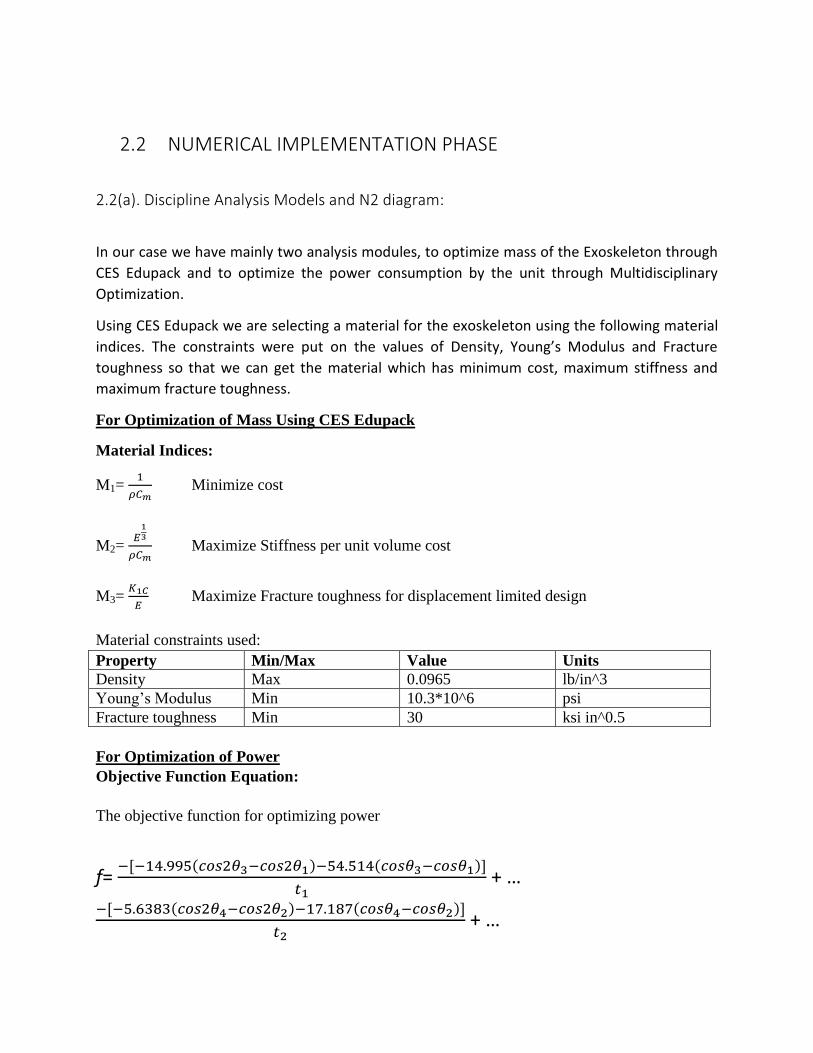
2.2 NUMERICAL IMPLEMENTATION PHASE
2.2(a). Discipline Analysis Models and N2 diagram:
In our case we have mainly two analysis modules, to optimize mass of the Exoskeleton through
CES Edupack and to optimize the power consumption by the unit through Multidisciplinary
Optimization.
Using CES Edupack we are selecting a material for the exoskeleton using the following material
indices. The constraints were put on the values of Density, Young’s Modulus and Fracture
toughness so that we can get the material which has minimum cost, maximum stiffness and
maximum fracture toughness.
For Optimization of Mass Using CES Edupack
Material Indices:
M1=
Minimize cost
M2=
Maximize Stiffness per unit volume cost
M3=
Maximize Fracture toughness for displacement limited design
Material constraints used:
Property Min/Max Value Units
Density Max 0.0965 lb/in^3
Young’s Modulus Min 10.3*10^6 psi
Fracture toughness Min 30 ksi in^0.5
For Optimization of Power
Objective Function Equation:
The objective function for optimizing power
f=
+ …
+ …

+ …
N2 Diagram:
Figure 5: N2 diagram
2.2(b). Block diagram of analysis modules Module 1:
CES EduPack is used to screen the best candidate material.
Solidworks is used to generate the shape of the exoskeleton.
Cost is used as a constraint.
Shape, l, b, w, Weight it has to support
Support for leg
Maximize Stiffness(E)
Maximize Fracture Toughness (K1c)
Minimize mass (m)

Module 2:
Found the optimum values of theta (1-4), t1 and t2 according to the different parameter values of
the frame.
Module 3:
2.2(c). Starting point values for design parameters
Starting point values for our design were based upon human observations and taking prior
designs into considerations. The average height and mass of a human being were assumed and
accordingly estimated. Similarly, the dimensions of the exoskeleton structure were based upon
the average dimensions of a human’s limb.
These starting point values were sufficient to determine the mass of the system and also
formulate the physical equations required to calculate the power requirement for each of the
four motors. These values helped to keep the design calculations in a feasible range as per the
functional requirements mentioned.
The starting set taken for to calculate the objective function is as follows:
x0 = [ 5.1 ; 5 ; 4.3 ; 4.1 ; 0.7 ; 1.3 ];
Power = 138.14W
l, b, w Movement
Control unit
Angles of motion(Theta 1-4 )
Time : t1, t2
Angles of motion(Theta 1-4 )
Time : t1, t2 Power Unit
Minimize total power
consumption

2.2(d). Design of Experiment
For the design of experiments, we chose to go with the full factorial approach. For our project,
we decided to take all the possible combinations of the design parameters of Θ1, Θ2, Θ3, Θ4, t1, t2
since we did not have a very large number of parameters to solve and through this method we
could also cover a bigger design space. The individual powers required for each motor were
calculated and the final total power was plotted in the form of a scatter plot.
The following code was used in MATLAB to model the full factorial experiment:
Figure 6: Design of Experiment – full factorial code

Figure 7: Design of Experiment – scatter plot
2.3 Optimization phase
2.3(a). Gradient-based algorithm
The gradient-based algorithm chosen for our optimizer was the Sequential Quadratic
Programming (SQP) algorithm. We used the FMINCON in-built function from MATLAB to find
the minimum value of the power required after formulating our objective function. This
function was used since we had a combination of inequality and equality constraints in out
design and the hessian would have taken a long time to compute if other gradient based
methods had been selected.
The code used to implement SQP in MATLAB is as follows:
Figure 8: Gradient based algorithm – main function using Fmincon

Figure 9: Gradient based algorithm – objective function
Figure 10: Gradient based algorithm – constraints function
2.3(b). Formal Optimization problem statement
Design variables ] = [ ]
The objective function ->
min [ ] =
+ …
+ …

+ …
subject to:
The six parameters which have been considered here are directly linked with the functional
requirements. The angular rotation values are responsible for the motion of the joints and the
four motors provide the torque to lift the knee and leg to provide a motion cycle.
Additional Objective:
We considered an additional objective to minimize the mass of the frame of the exoskeleton by
performing a material selection analysis to get the best candidate material for our design
model.
The following procedure was used:
Minimization of mass of exoskeleton frame to using CES EDUPACK:
Selection Criteria
Aluminum alloys are generally used when properties like density, stiffness and fracture
toughness are of importance for material selection. Aluminum 6022 T43 alloy is the most
commonly used alloy used for these property related applications. The values of these three
properties below of Aluminum 6022T43 are taken as constraint values and are given as
selection criteria in the software to filter materials to select the best candidate material.
Material Density: Less than Aluminum 6022 T43
Young’s Modulus: More than Aluminum 6022 T43
Fracture Toughness: More than or equal to Aluminum 6022 T43

Function Exoskeleton frame
Constraints Material Density Young’s Modulus Fracture toughness All dimensions are specified Corrosion resistant
Objectives Minimize mass Maximize Stiffness Minimize cost
Free variable Choice of material
Translation
Property Min/Max Value Units
Density Max 0.0965 lb/in^3
Young’s Modulus Min 10.3*10^6 psi
Fracture toughness Min 30 ksi in^0.5
Material indices used
Cost can be minimized by minimizing the overall mass of the material used.
M1=
Minimize cost
M2=
Maximize Stiffness per unit volume cost
M3=
Maximize Fracture toughness for displacement limited design
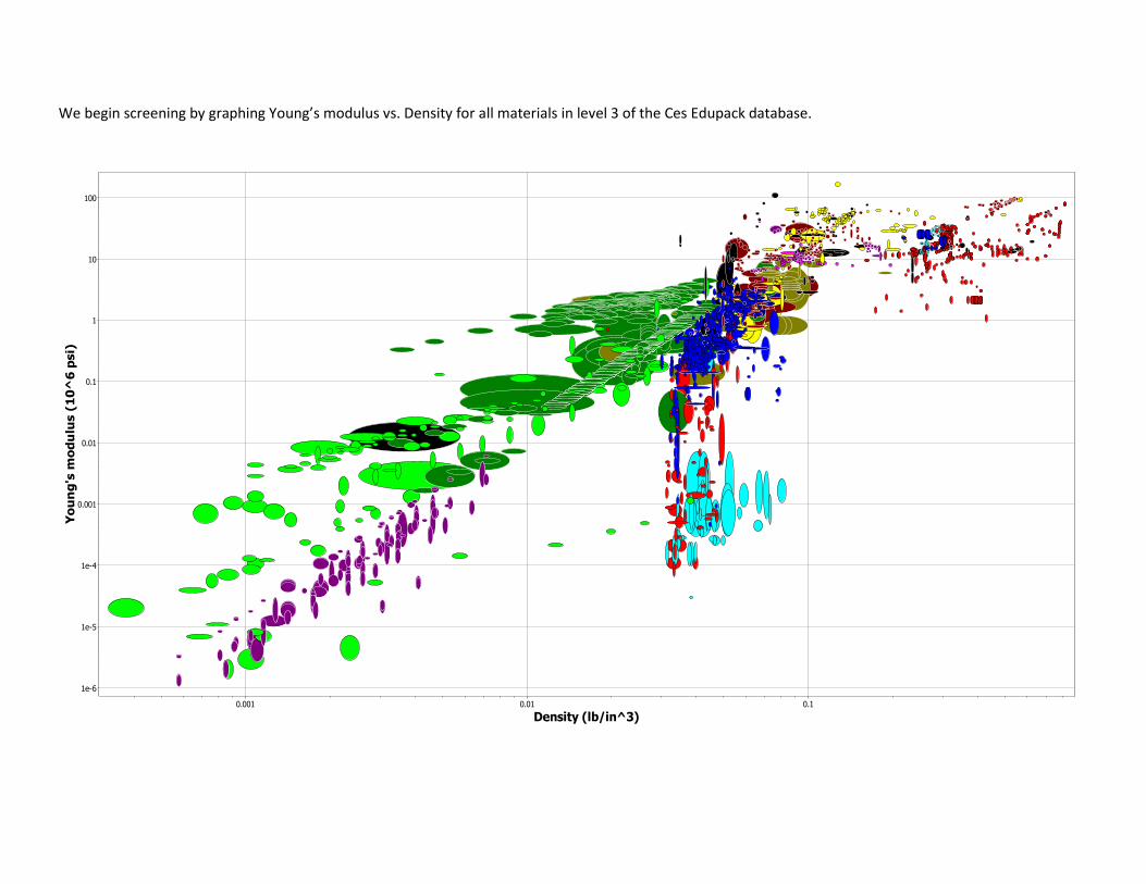
We begin screening by graphing Young’s modulus vs. Density for all materials in level 3 of the Ces Edupack database.
Density (lb/in^3)0.001 0.01 0.1
Yo
un
g's
mo
du
lus (
10
^6
psi)
1e-6
1e-5
1e-4
0.001
0.01
0.1
1
10
100

Screening out the materials that do not satisfy initial requirements for Density and Young’s Modulus of Aluminum 6022 T43 and eliminating failed part records
This graph still contains many possible materials, and hence needs to be refined further
Eliminating the materials that do not meet the thermal expansion and Fracture toughness criteria.
Density (lb/in^3)0.035 0.04 0.045 0.05 0.055 0.06 0.065 0.07 0.075 0.08 0.085 0.09 0.095 0.1 0.105 0.11 0.115
Yo
un
g's
mo
du
lus (
10
^6
psi)
2
5
10
20
50
100

Zooming in and adding guidelines corresponding to
We are left with mainly with carbon fiber composites, two ceramics and a few Aluminum alloys.
Graphing Fracture toughness vs. Young’s Modulus
Density (lb/in^3)0.044 0.046 0.048 0.05 0.052 0.054 0.056 0.058 0.06 0.062 0.064 0.066 0.068 0.07 0.072 0.074 0.076 0.078 0.08 0.082 0.084 0.086 0.088 0.09 0.092 0.094 0.096 0.098 0.1 0.102 0.1040.1060.108 0.11 0.112
Yo
un
g's
mo
du
lus (
10
^6
psi)
10
20
50
Cyanate ester/HM carbon fiber, UD composite, quasi-isotropic laminate
PEEK/IM carbon fiber, UD composite, 0° lamina
Epoxy/HS carbon fiber, UD composite, 0° lamina
BMI/HS carbon fiber, UD composite, 0° lamina
Epoxy/aramid fiber, UD composite, 0° lamina
Aluminum, A356.0, sand cast, T6
Aluminum, 443.0, sand cast, F
Aluminum, 2297, wrought, T87
Aluminum, 8091, wrought, T6
Aluminum, 8090, wrought, T851
Alumino silicate/Nextel 720. 45Vf - quasi-isotropic laminate
Alumino silicate/Nextel 720, 45Vf - woven fabric
Epoxy SMC (carbon fiber)
Cyanate ester/HM carbon fiber, UD composite, 0° lamina
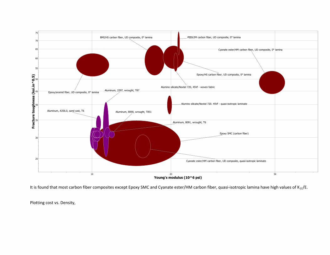
It is found that most carbon fiber composites except Epoxy SMC and Cyanate ester/HM carbon fiber, quasi-isotropic lamina have high values of K1C/E.
Plotting cost vs. Density,
Young's modulus (10^6 psi)10 20 50
Fra
ctu
re t
ou
gh
ne
ss (
ksi.
in^
0.5
)
25
30
35
40
45
50
55
60
65
70
75
Epoxy/HS carbon fiber, UD composite, 0° lamina
Cyanate ester/HM carbon fiber, UD composite, quasi-isotropic laminate
Alumino silicate/Nextel 720. 45Vf - quasi-isotropic laminate
Aluminum, 8091, wrought, T6
Aluminum, 8090, wrought, T851Aluminum, A356.0, sand cast, T6
Aluminum, 2297, wrought, T87
BMI/HS carbon fiber, UD composite, 0° lamina
Alumino silicate/Nextel 720, 45Vf - woven fabric
PEEK/IM carbon fiber, UD composite, 0° lamina
Cyanate ester/HM carbon fiber, UD composite, 0° lamina
Epoxy SMC (carbon fiber)
Epoxy/aramid fiber, UD composite, 0° lamina

Restricting cost of the material to $30/lb, we can eliminate BMI/HS carbon fiber, PEEK/IM carbon fiber, Cyanate ester/HM carbon fiber and Alumino
Silicate/Nextel 720.
Density (lb/in^3)0.05 0.055 0.06 0.065 0.07 0.075 0.08 0.085 0.09 0.095 0.1 0.105 0.11 0.115 0.12 0.125 0.13 0.135 0.14
Pri
ce
(U
SD
/lb
)
1
10
100
1000
Aluminum, 5754, wrought, O
Aluminum, 2297, wrought, T87
Aluminum, 8091, wrought, T6
Aluminum, 8090, wrought, T851
Alumino silicate/Nextel 720. 45Vf - quasi-isotropic laminate
PEEK/IM carbon fiber, UD composite, 0° lamina
BMI/HS carbon fiber, UD composite, 0° lamina
Cyanate ester/HM carbon fiber, UD composite, quasi-isotropic laminate
Epoxy/aramid fiber, UD composite, 0° lamina
Epoxy/HS carbon fiber, UD composite, 0° lamina
Epoxy SMC (carbon fiber)

As can be seen from the graphs, the aluminum alloys are heavier for the same mechanical
properties. However, some of them are cheaper and offer only slightly reduced property values.
Hence to determine the choice of material we consider a penalty function and consider the
following five materials:
Table 3: Material Properties
Material Price (USD/lb) Density (lb/in^3) Young’s modulus (10^6 psi)
Fracture toughness (ksi in^0.5)
Epoxy SMC (Carbon fiber)
11 0.056 16 30
Aluminum 8090 T851
6.45 0.092 11.9 31
Epoxy/HS carbon fiber, UD composite, 0° lamina
18 0.0565 20.55 60.85
Epoxy/aramid fiber, UD composite, 0° lamina
28.7 0.0499 10.15 56.9
Aluminum, 8091, wrought, T6
6.5 0.0934 11.45 31.4
The table represents the properties of five of the possible materials that look the best.
Table 4: Material Index Values
Epoxy SMC (Carbon fiber)
Aluminum 8090 T851
Epoxy/HS carbon fiber, UD composite, 0° lamina
Epoxy/aramid fiber, UD composite, 0° lamina
Aluminum, 8091, wrought, T6
M1 1.623 1.6852 0.9833 0.6983 1.6472
M2 4.091 3.847 2.693 1.512 3.713
M3 1.875 2.605 2.961 5.606 2.742
Another consideration is the resistance to corrosion due to exposure to the environment.
Epoxy/aramid fiber, UD composite, 0° lamina is fairly durable against UV radiation while the
others are much better. Since the exoskeleton could be exposed to outdoor environment,
better durability against UV radiation is preferred and hence Epoxy/aramid fiber, UD
composite, 0° lamina is not a very good choice.

The choice among these is evaluated using a penalty function which serves as a mean to
aggregate the various objectives into a single objective function, formulated such that its
minimum defines the most preferable solution.
Z= C1M1 + C2M2 + C3M3
The exchange constants are defined as follows:
C1=10: Mass and cost are the primary parameters that are being considered for the design as
the lightest material will reduce the load on the person to use the exoskeleton
C2=5: Stiffness is the next important parameter as the frame needs to maintain its shape to
ensure the person does not fall down while walking.
C3=1: The fracture toughness although important is not as important as the other parameters
as the exoskeleton not be subjected to very high stresses.
Table 5: Penalty Function values
Epoxy SMC (Carbon fiber)
Aluminum 8090 T851
Epoxy/HS carbon fiber, UD composite, 0° lamina
Epoxy/aramid fiber, UD composite, 0° lamina
Aluminum, 8091, wrought, T6
Z values 38.56 38.692 26.259 20.149 37.779
Aluminum 8090 T851 has the highest Z values and can be regarded as a good material for the
application. However, Aluminum 8090 and Aluminum 8091 are no longer being produced and
they have been replaced by newer alloys.
The material with the next highest value is considered.
Hence, Epoxy SMC (Carbon Fiber) is the chosen material for the exoskeleton. Frame made from
this material will be the lightest and stiffest material with respect to cost considerations.
After finding the best candidate the functional requirement for the frame of the exoskeleton is
solved by minimization of the mass of the exoskeleton frame by choosing the appropriate
density of the material.
Total mass of the exoskeleton frame = 3.992 lb ~ 4lb

2.3(c). Optimizer convergence and better results:
The following results were obtained from the SQP optimizer program:
>> main_sqp
Local minimum found that satisfies the constraints.
Optimization completed because the objective function is non-decreasing in feasible
directions, to within the default value of the optimality tolerance and constraints are satisfied
to within the default value of the constraint tolerance.
<stopping criteria details>
x =
5.4950
5.2300
4.0200
4.1800
0.5000
0.5000
fval =
-364.4690
theta =
315.0122
300.0007
240.0006
230.0082

t =
0.5000
0.5000
Hence the minimum optimized power found is -364.469 W.
The value obtained is much better than the starting power value obtained. The power obtained from the
initial assumption of variables was lower but the constraints were violated which could not be seen as a
feasible design.
The values obtained seems to be the global minimum since we didn’t get better results for multiple
iterations with different starting points. The obtained value also satisfies all constraints and hence can
be viewed as global minimum.
2.3(d). Sensitivity Analysis
The objective function is defined as:
f=
+ …
+ …
+ …
Calculating the differential values with respect to the individual parameters:
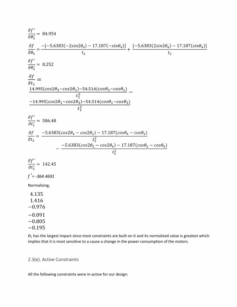
f *= -364.4691
Normalizing,
Θ1 has the largest impact since most constraints are built on it and its normalized value is greatest which
implies that it is most sensitive to a cause a change in the power consumption of the motors.
2.3(e). Active Constraints
All the following constraints were in-active for our design:
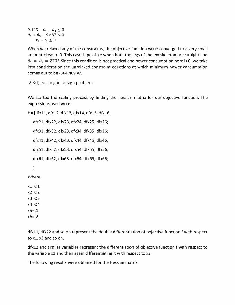
When we relaxed any of the constraints, the objective function value converged to a very small
amount close to 0. This case is possible when both the legs of the exoskeleton are straight and
Since this condition is not practical and power consumption here is 0, we take
into consideration the unrelaxed constraint equations at which minimum power consumption
comes out to be -364.469 W.
2.3(f). Scaling in design problem
We started the scaling process by finding the hessian matrix for our objective function. The
expressions used were:
H= [dfx11, dfx12, dfx13, dfx14, dfx15, dfx16;
dfx21, dfx22, dfx23, dfx24, dfx25, dfx26;
dfx31, dfx32, dfx33, dfx34, dfx35, dfx36;
dfx41, dfx42, dfx43, dfx44, dfx45, dfx46;
dfx51, dfx52, dfx53, dfx54, dfx55, dfx56;
dfx61, dfx62, dfx63, dfx64, dfx65, dfx66;
]
Where,
x1=Θ1
x2=Θ2
x3=Θ3
x4=Θ4
x5=t1
x6=t2
dfx11, dfx22 and so on represent the double differentiation of objective function f with respect
to x1, x2 and so on.
dfx12 and similar variables represent the differentiation of objective function f with respect to
the variable x1 and then again differentiating it with respect to x2.
The following results were obtained for the Hessian matrix:

H= 1.0e+03 * [
0.1543 0 0 0 0.5482 0
0 -0.0107 0 0 0 0.1972
0 0 0.2290 0 -0.1699 0
0 0 0 0.0599 0 -0.0165
0.5482 0 -0.1699 0 -2.3461 0
0 0.1972 0 -0.0165 0 -0.5696]
On finding the Eigen values for the above matrix we got the following results:
λ1 =-247.1288598848391
λ2 = 291.5159004076417
λ3 = 216.07269844075182
λ4 = 62.58174522541338
λ5 = -632.5308318048131
λ6 = 49.549086579399635
From these values we found that the Hessian condition number = λmax/λmin = -0.461
Since this value is not very high hence our design variables were not scaled and the new
optimum function value was not required to be found.
2.3(g). Heuristic technique For our design problem, we chose to use the genetic algorithm optimizer. This was due to the
fact that Particle Swarm Optimization was difficult to implement with 6 variables. Also, from
the genetic algorithm, the iteration history along with max fitness values can be plotted easily.
Genetic Algorithm provides various options like mutation, crossover rate to be tuned for better
efficiency of result.
The following results were obtained from the Genetic Algorithm code:

Figure 11: Genetic Algorithm – Generation history plot
Figure 12: Genetic Algorithm - Average fitness plot

The optimizer produced the following results:
The minimum power required: -317.995 W
2.3(h). Comparison of results with gradient-based approach
The gradient based approach produced the following result for power consumption:
364.469 W
The value obtained from the heuristic technique is:
317.995 W
We can see the values obtained are close to each other. In this case, the heuristic approach
produced better results than the gradient based approach.
Genetic Algorithm tuned parameter set:
Table 6: Parameter Tune for GA code
Probability of crossing over
Probability of mutation Fitness
0.5 0.06 672.715 0.7 0.1 317.995
0.75 0.15 377.122 0.8 0.2 543.85
0.6 0.3 405.64
0.8 0.4 344.456
We can see that the fitness function has minimum value for the combination:
Probability of crossing over = 0.7; Probability of mutation = 0.1
2.3(i). Multiple objective Optimization formulation
For our design problem, there was only one problem to optimize i.e the power consumption.
Our mass was minimized by choosing the best density material, thereby reducing the mass as
much as possible. Optimizing the mass using a numerical technique wasn’t feasible since the list
of densities, moduli, etc. could not be imported into MATLAB.

Hence, our design model is the lightest and consumes the least power.
2.3(j). Pareto Front
Since our design model is based on a single objective function, hence the Pareto front
estimation was not found.
2.3(k). 3 View drawing
Figure 14: Side view of Exoskeleton
Figure 134: Front View of Exoskeleton
Figure 15: Top View of Exoskeleton

Appendix Calculation of exoskeleton and total mass
Density of material (Epoxy SMC/Carbon fiber) based on material optimization using CESEdupack:
ρ = 0.056 lb/in3
Radius of the members r = 10mm ~ 0.4in
Lthigh = 420mm = 16.65in
Lcalf = 480mm = 18.89in
Mass of thigh member Methigh = πr2Lthighρ
= π*0.42*16.5*0.056
= 0.464 lb
Mass of calf member Mecalf = πr2Lcalfρ
= π*0.42*18.89*0.056
= 0.532 lb
The ankle support and the base of the exoskeleton is considered to be made of steel instead of Epoxy
SMC/Carbon fiber since forming the composite into the complex shape of the foot will be difficult. The
mass of the ankle and its attachments is assumed to be 1lb per foot.
Meankle = 1lb
The total mass that the motors will need to move is calculated by adding the mass of the human leg to
the exoskeleton mass. To find the mass of the leg, we consider the following mass percentages of the
thigh, calf and foot compared to the total mass of the body:
Segment Average percentage Mass for an 80kg person
Thigh 14.47 28.65
Calf 4.57 9.05
Foot 1.33 2.65
Adding the masses of the members to the above mass,
Mthigh = 29.114 lb
Mcalf = 9.582 lb
Mankle = 3.65 lb

Motor Power calculation
Power of Motor 1 (Hip joint) P1 = Power consumed by motor 1
T1 = Torque for motor 1
ω1 = Angular velocity of motor 1
P1 = T1 * ω1
P1 =
Power of Motor 2 (Knee joint) P2 = Power consumed by motor 2
T2 = Torque for motor 2
ω2 = Angular velocity of motor 2
P2 = T2 * ω2
P2 =
Power of Motor 3 (Hip joint) P3 = Power consumed by motor 3
T3 = Torque for motor 3
ω3 = Angular velocity of motor 3
P3 = T3 * ω3
P3 =
Power of Motor 4 (Knee joint) P4 = Power consumed by motor 4
T4 = Torque for motor 4
ω4 = Angular velocity of motor 4

P4 = T4 * ω4
P4 =