design optimization of drone propeller - · pdf filedesign optimization of drone propeller ......
TRANSCRIPT
1
PROJECT TITLE
Design Optimization Of
Drone Propeller
PROJECT NO: SDPE-AM-G8
SCHOOL OF ENGINEERING
2
COURSE: WSQ SPECIALIST DIPLOMA IN PRECISION ENGINEERING
(ADDITIVE MANUFACTURING)
PROJECT TITLE: _Design Optimization of Drone Propeller_______________
PROJECT NO: SDPE-AM-G8_______________
PROJECT DURATION: 10 AUG 2016 TO 19 OCT 2016
PROJECT MEMBER(S):
NAME ADMIN. NO. ELECTIVE
LAI MUN HONG 15C010U EAM506
SIM CHOO HUAT 15C021C EAM506
SUPERVISORS: Mr. SNEHARAJ MALANKAD
Proposed by:
SEG (M): [ √ ]
DATE OF SUBMISSION: 19 OCT 2016
SCHOOL OF ENGINEERING
3
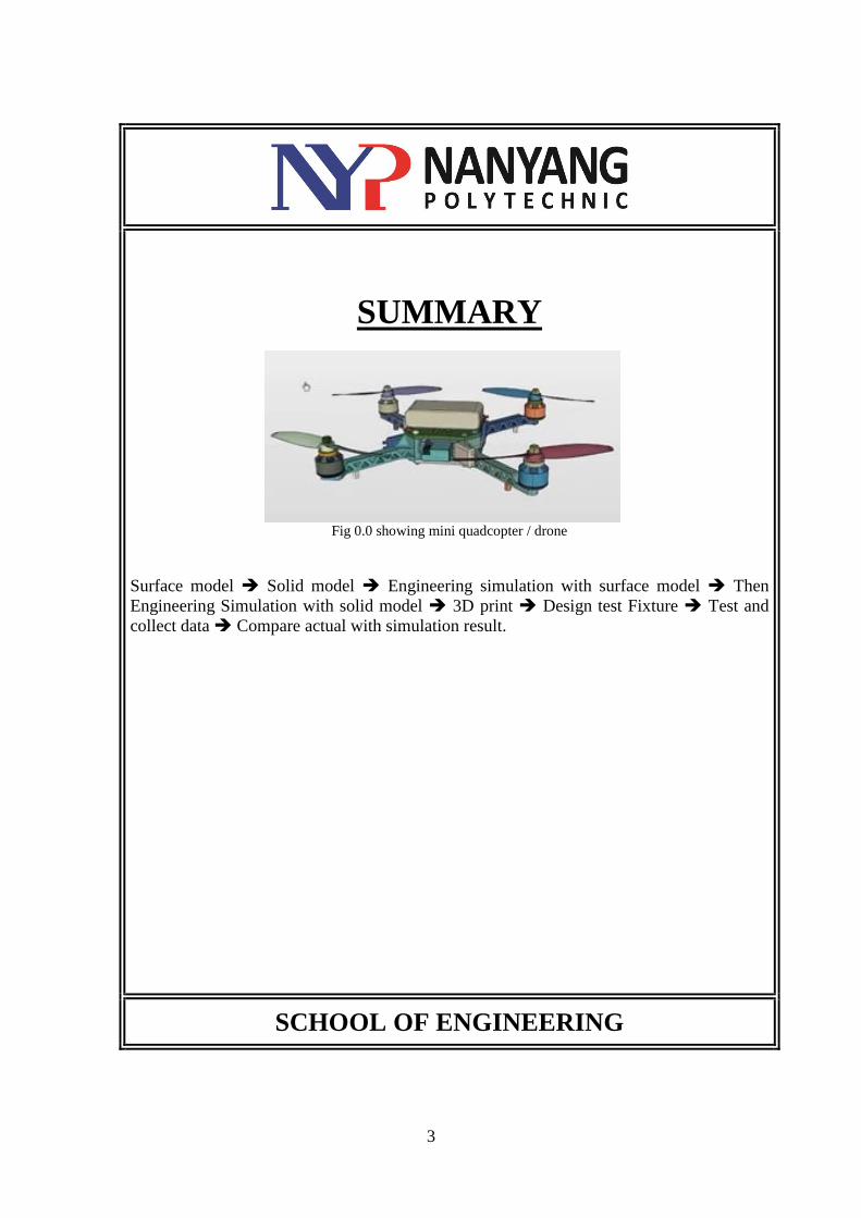
SUMMARY
Fig 0.0 showing mini quadcopter / drone
Surface model Solid model Engineering simulation with surface model Then
Engineering Simulation with solid model 3D print Design test Fixture Test and
collect data Compare actual with simulation result.
SCHOOL OF ENGINEERING
4
ACKNOWLEDGEMENTS
Anna Flessner
Engineer, Community Manager at SimScale GmbH
Sneharaj Malankad
Senior Lecturer, at Nanyang Polytechnic
SCHOOL OF ENGINEERING
5
TABLE OF CONTENTS
Summary 3
Acknowledgements 4
Chapter 1 Aerodynamic of Drone 6
Chapter 2 Design Consideration for Propeller 7
Chapter 3 Design and CAD Model 8-10
Chapter 4 Mesh & Simulation Setup 11-13
Chapter 5 Simulation Result 14-16
Chapter 6 Test Plan 17-18
Conclusion 19
Appendix 20
Gantt Chart 21
References 22
SCHOOL OF ENGINEERING
6
CHAPTER 1
1.0 AERODYNAMIC OF DRONE
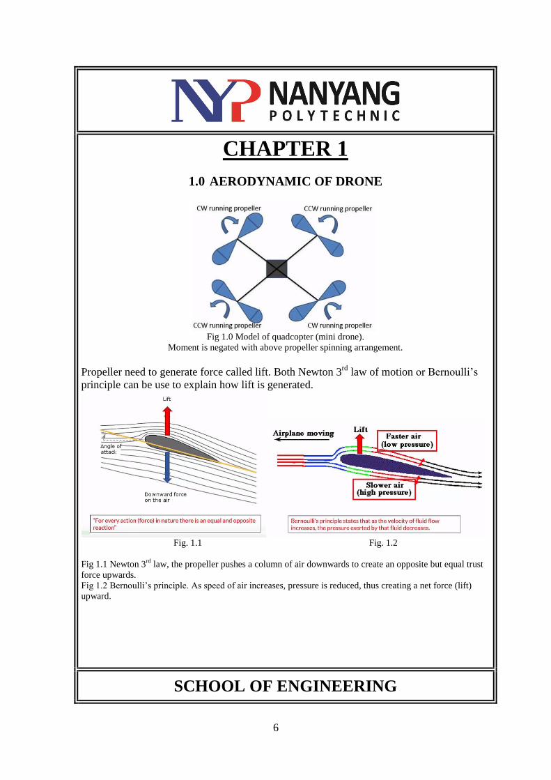
Fig 1.0 Model of quadcopter (mini drone).
Moment is negated with above propeller spinning arrangement.
Propeller need to generate force called lift. Both Newton 3rd
law of motion or Bernoulli’s
principle can be use to explain how lift is generated.
Fig. 1.1 Fig. 1.2
Fig 1.1 Newton 3rd
law, the propeller pushes a column of air downwards to create an opposite but equal trust
force upwards.
Fig 1.2 Bernoulli’s principle. As speed of air increases, pressure is reduced, thus creating a net force (lift)
upward.
SCHOOL OF ENGINEERING
7
CHAPTER 2
2.0 DESIGN CONSIDERATION FOR PROPELLER
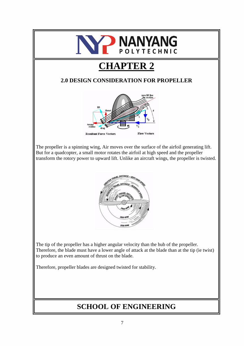
The propeller is a spinning wing, Air moves over the surface of the airfoil generating lift.
But for a quadcopter, a small motor rotates the airfoil at high speed and the propeller
transform the rotory power to upward lift. Unlike an aircraft wings, the propeller is twisted.
The tip of the propeller has a higher angular velocity than the hub of the propeller.
Therefore, the blade must have a lower angle of attack at the blade than at the tip (ie twist)
to produce an even amount of thrust on the blade.
Therefore, propeller blades are designed twisted for stability.
SCHOOL OF ENGINEERING
8
CHAPTER 3
3 DESIGN AND CAD MODEL
Software: Solidworks and OnShape
Propeller Design
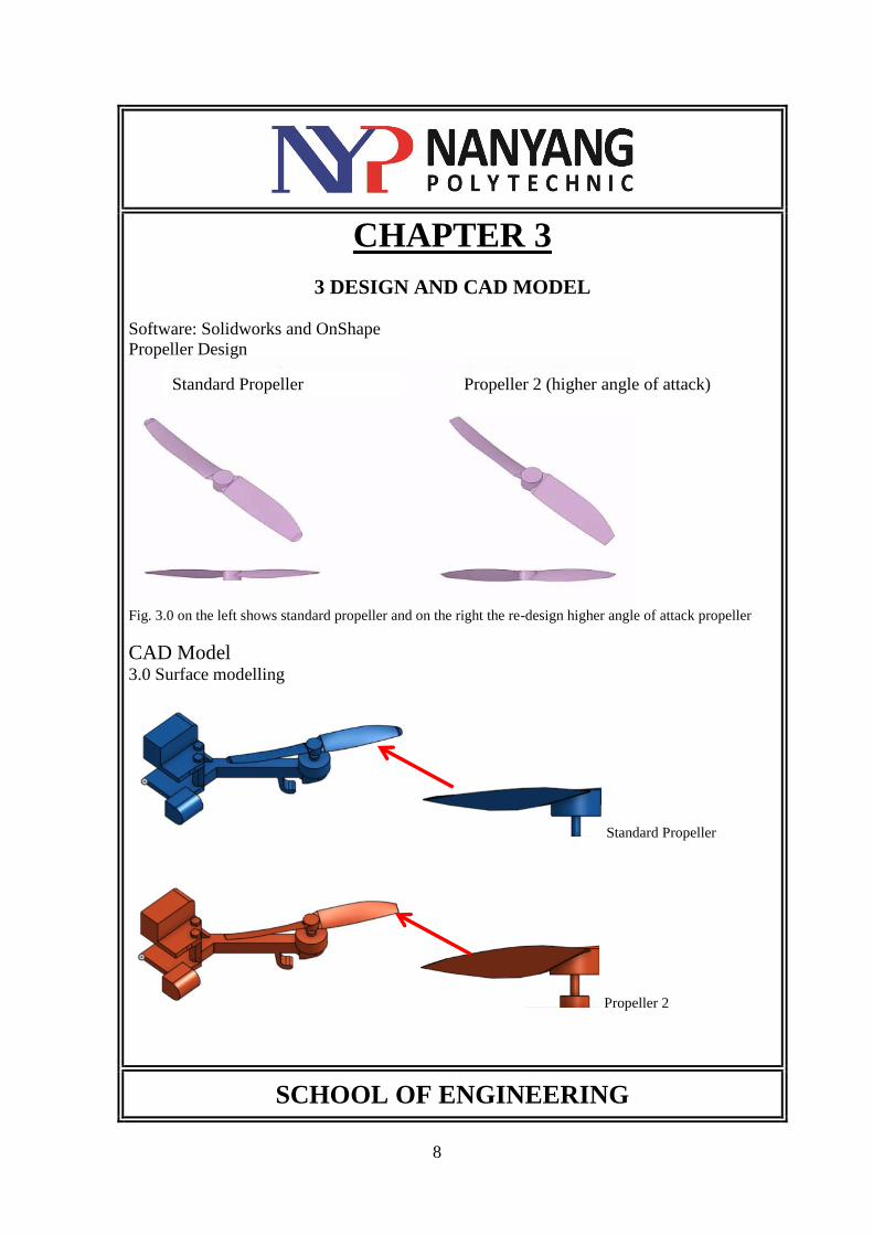
Fig. 3.0 on the left shows standard propeller and on the right the re-design higher angle of attack propeller
CAD Model 3.0 Surface modelling
Standard Propeller
Propeller 2
SCHOOL OF ENGINEERING
Standard Propeller Propeller 2 (higher angle of attack)
9
CHAPTER 3
3 DESIGN AND CAD MODEL
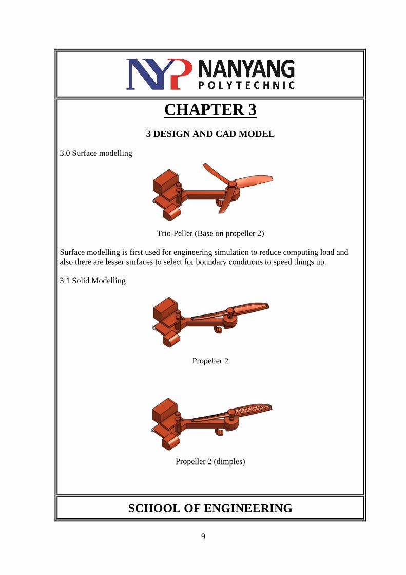
3.0 Surface modelling
Trio-Peller (Base on propeller 2)
Surface modelling is first used for engineering simulation to reduce computing load and
also there are lesser surfaces to select for boundary conditions to speed things up.
3.1 Solid Modelling
Propeller 2
Propeller 2 (dimples)
SCHOOL OF ENGINEERING
10
CHAPTER 3
3 DESIGN AND CAD MODEL
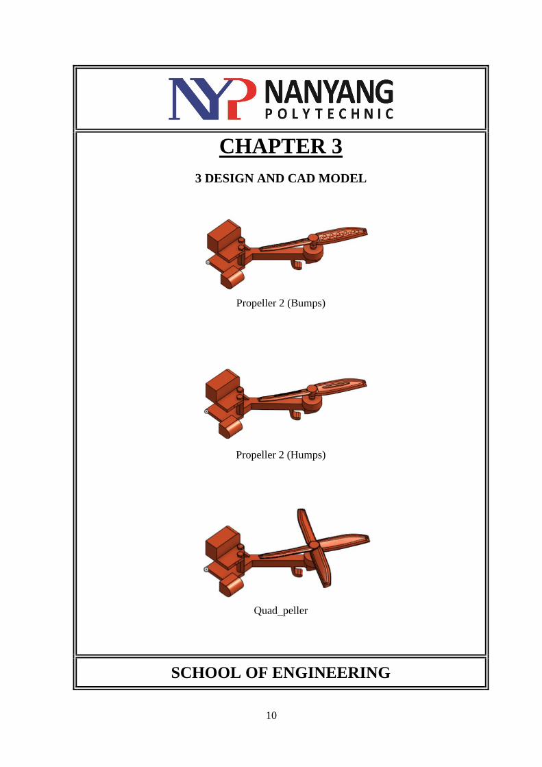
Propeller 2 (Bumps)
Propeller 2 (Humps)
Quad_peller
SCHOOL OF ENGINEERING
11
CHAPTER 4
4. MESH & SIMULATION SETUP
Software: Simscale and Solidworks
4.0 Create project in Simscale
4.1 Upload CAD (step file)
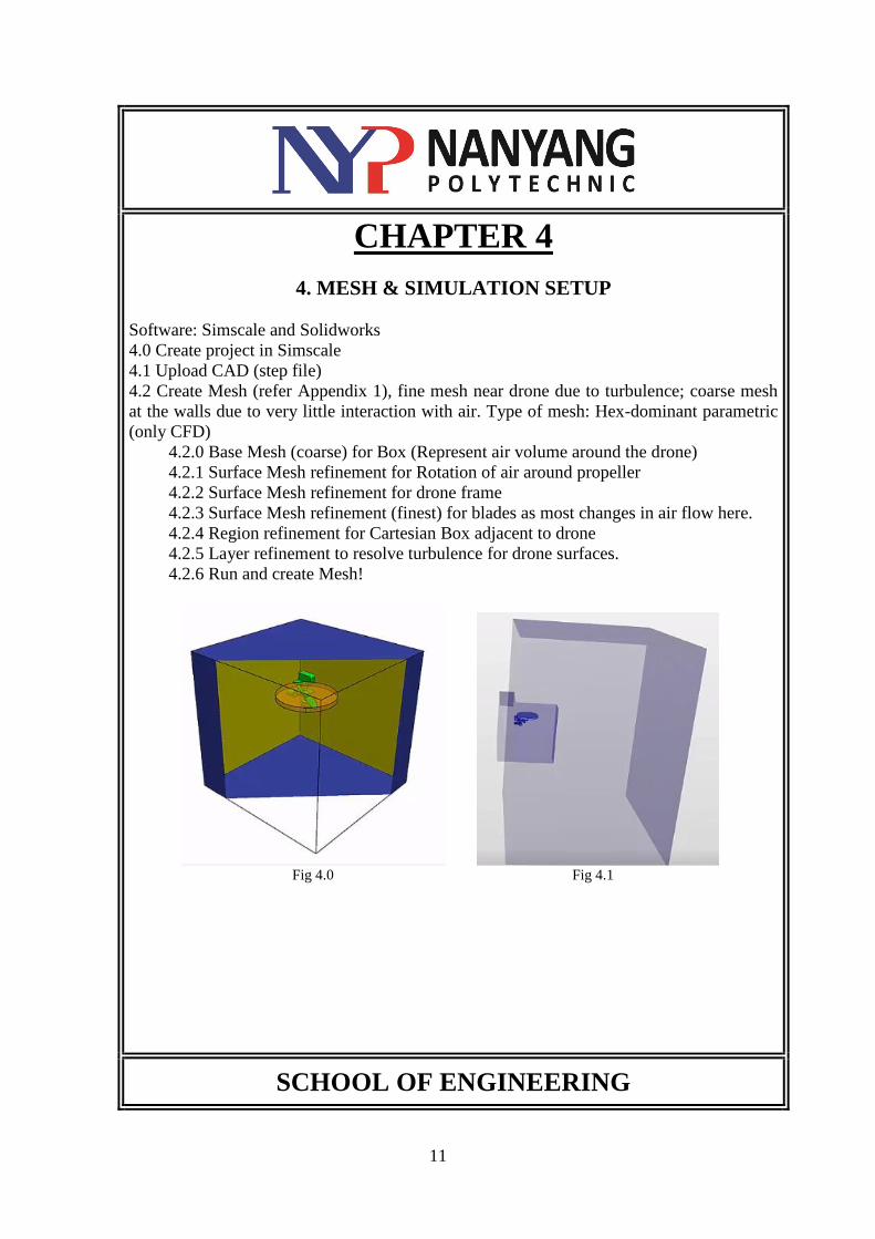
4.2 Create Mesh (refer Appendix 1), fine mesh near drone due to turbulence; coarse mesh
at the walls due to very little interaction with air. Type of mesh: Hex-dominant parametric
(only CFD)
4.2.0 Base Mesh (coarse) for Box (Represent air volume around the drone)
4.2.1 Surface Mesh refinement for Rotation of air around propeller
4.2.2 Surface Mesh refinement for drone frame
4.2.3 Surface Mesh refinement (finest) for blades as most changes in air flow here.
4.2.4 Region refinement for Cartesian Box adjacent to drone
4.2.5 Layer refinement to resolve turbulence for drone surfaces.
4.2.6 Run and create Mesh!
Fig 4.0 Fig 4.1
SCHOOL OF ENGINEERING
12
CHAPTER 4
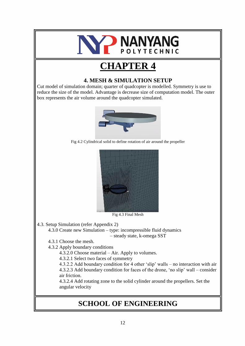
4. MESH & SIMULATION SETUP Cut model of simulation domain; quarter of quadcopter is modelled. Symmetry is use to
reduce the size of the model. Advantage is decrease size of computation model. The outer
box represents the air volume around the quadcopter simulated.
Fig 4.2 Cylindrical solid to define rotation of air around the propeller
Fig 4.3 Final Mesh
4.3. Setup Simulation (refer Appendix 2)
4.3.0 Create new Simulation – type: incompressible fluid dynamics
– steady state, k-omega SST
4.3.1 Choose the mesh.
4.3.2 Apply boundary conditions
4.3.2.0 Choose material – Air. Apply to volumes.
4.3.2.1 Select two faces of symmetry
4.3.2.2 Add boundary condition for 4 other ‘slip’ walls – no interaction with air
4.3.2.3 Add boundary condition for faces of the drone, ‘no slip’ wall – consider
air friction.
4.3.2.4 Add rotating zone to the solid cylinder around the propellers. Set the
angular velocity
SCHOOL OF ENGINEERING
13
CHAPTER 4
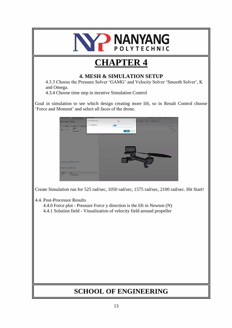
4. MESH & SIMULATION SETUP 4.3.3 Choose the Pressure Solver ‘GAMG’ and Velocity Solver ‘Smooth Solver’, K
and Omega.
4.3.4 Choose time step in iterative Simulation Control
Goal in simulation to see which design creating more lift, so in Result Control choose
‘Force and Moment’ and select all faces of the drone.
Create Simulation run for 525 rad/sec, 1050 rad/sec, 1575 rad/sec, 2100 rad/sec. Hit Start!
4.4. Post-Processor Results
4.4.0 Force plot - Pressure Force y direction is the lift in Newton (N)
4.4.1 Solution field - Visualization of velocity field around propeller
SCHOOL OF ENGINEERING
14
CHAPTER 5
5. SIMULATION RESULTS
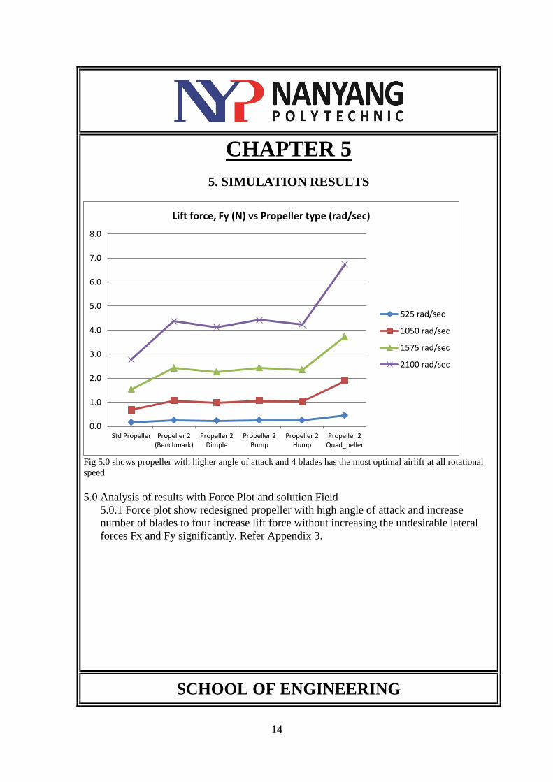
Fig 5.0 shows propeller with higher angle of attack and 4 blades has the most optimal airlift at all rotational
speed
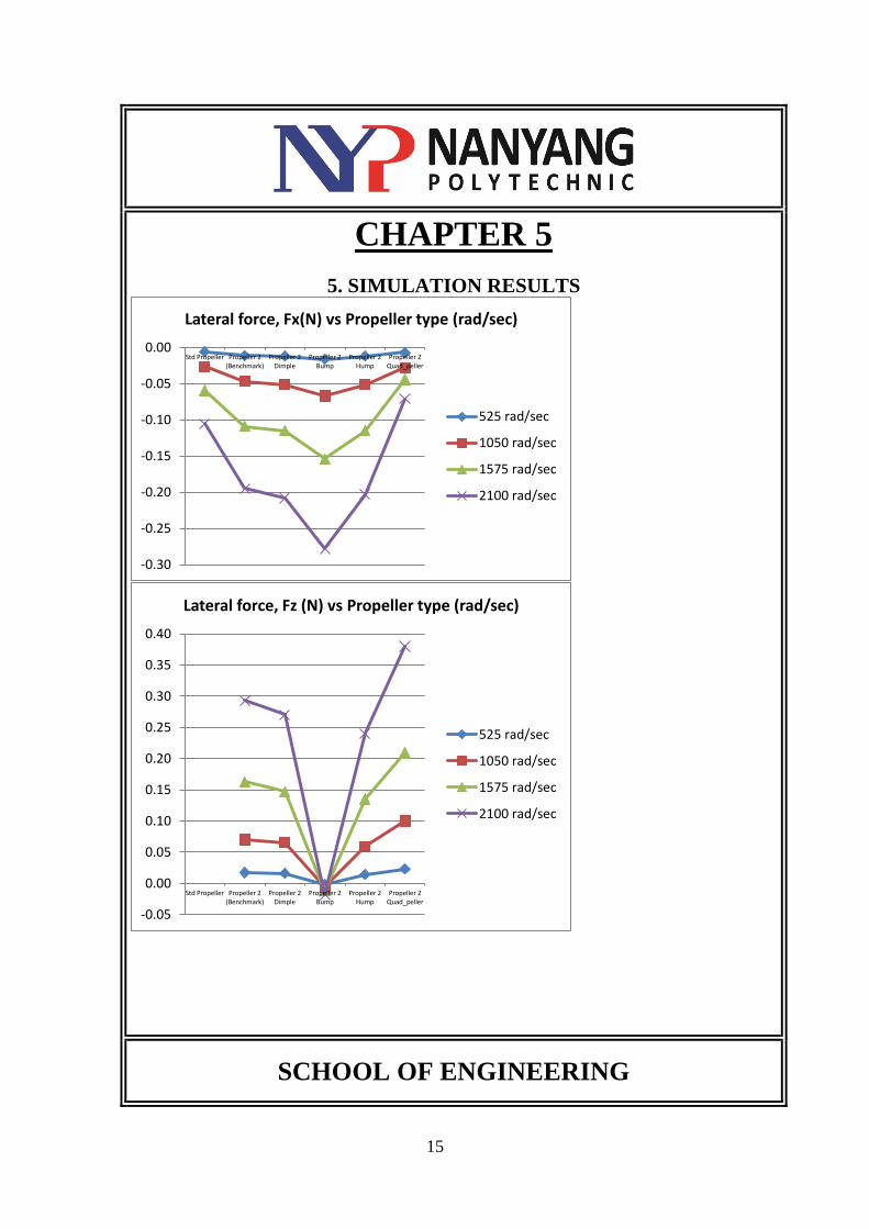
5.0 Analysis of results with Force Plot and solution Field
5.0.1 Force plot show redesigned propeller with high angle of attack and increase
number of blades to four increase lift force without increasing the undesirable lateral
forces Fx and Fy significantly. Refer Appendix 3.
SCHOOL OF ENGINEERING
0.0
1.0
2.0
3.0
4.0
5.0
6.0
7.0
8.0
Std Propeller Propeller 2(Benchmark)
Propeller 2Dimple
Propeller 2Bump
Propeller 2Hump
Propeller 2Quad_peller
Lift force, Fy (N) vs Propeller type (rad/sec)
525 rad/sec
1050 rad/sec
1575 rad/sec
2100 rad/sec
15
CHAPTER 5
5. SIMULATION RESULTS
SCHOOL OF ENGINEERING
-0.30
-0.25
-0.20
-0.15
-0.10
-0.05
0.00Std Propeller Propeller 2
(Benchmark)Propeller 2
DimplePropeller 2
BumpPropeller 2
HumpPropeller 2
Quad_peller
Lateral force, Fx(N) vs Propeller type (rad/sec)
525 rad/sec
1050 rad/sec
1575 rad/sec
2100 rad/sec
-0.05
0.00
0.05
0.10
0.15
0.20
0.25
0.30
0.35
0.40
Std Propeller Propeller 2(Benchmark)
Propeller 2Dimple
Propeller 2Bump
Propeller 2Hump
Propeller 2Quad_peller
Lateral force, Fz (N) vs Propeller type (rad/sec)
525 rad/sec
1050 rad/sec
1575 rad/sec
2100 rad/sec
16
CHAPTER 5
5. SIMULATION RESULTS
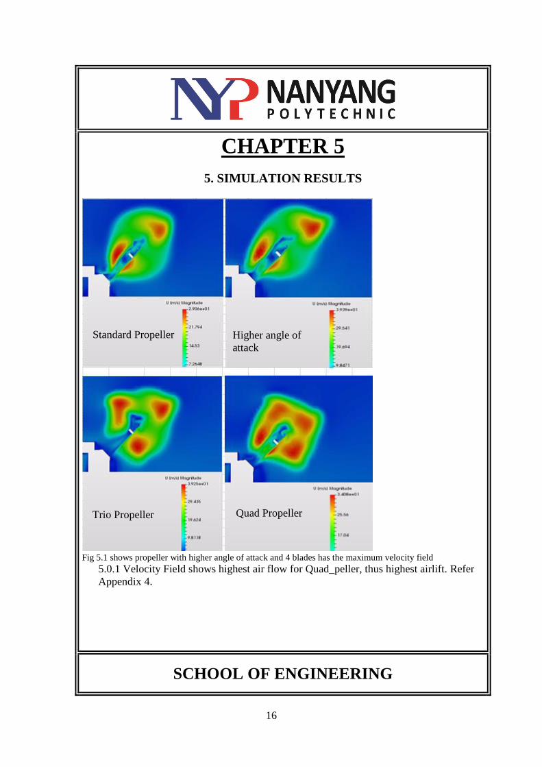
Fig 5.1 shows propeller with higher angle of attack and 4 blades has the maximum velocity field
5.0.1 Velocity Field shows highest air flow for Quad_peller, thus highest airlift. Refer
Appendix 4.
SCHOOL OF ENGINEERING
Standard Propeller Higher angle of
attack
Trio Propeller Quad Propeller
17
CHAPTER 6
6. TEST PLAN
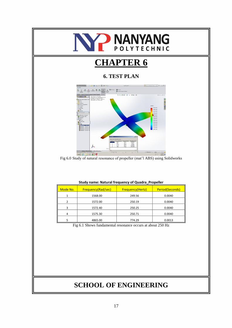
Fig 6.0 Study of natural resonance of propeller (mat’l ABS) using Solidworks
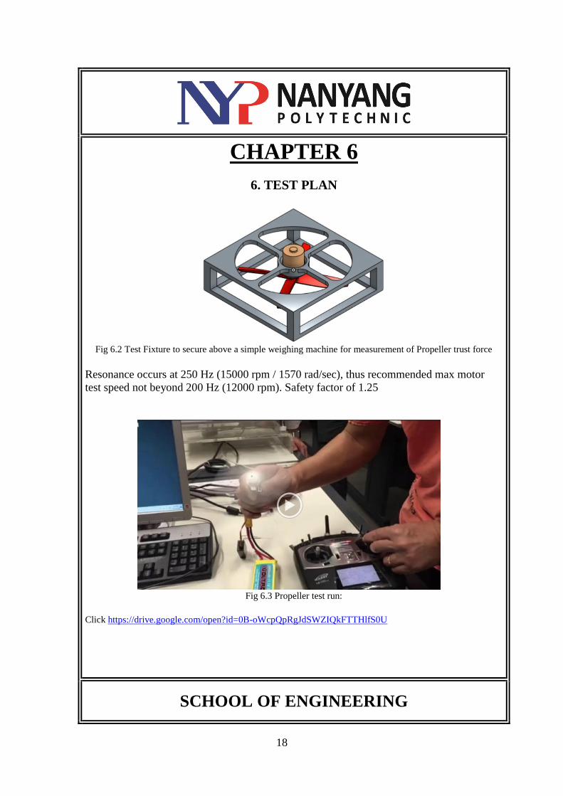
Study name: Natural frequency of Quadra_Propeller
Mode No. Frequency(Rad/sec) Frequency(Hertz) Period(Seconds)
1 1568.00 249.56 0.0040
2 1572.00 250.19 0.0040
3 1572.40 250.25 0.0040
4 1575.30 250.71 0.0040
5 4865.00 774.29 0.0013
Fig 6.1 Shows fundamental resonance occurs at about 250 Hz
SCHOOL OF ENGINEERING
18
CHAPTER 6
6. TEST PLAN
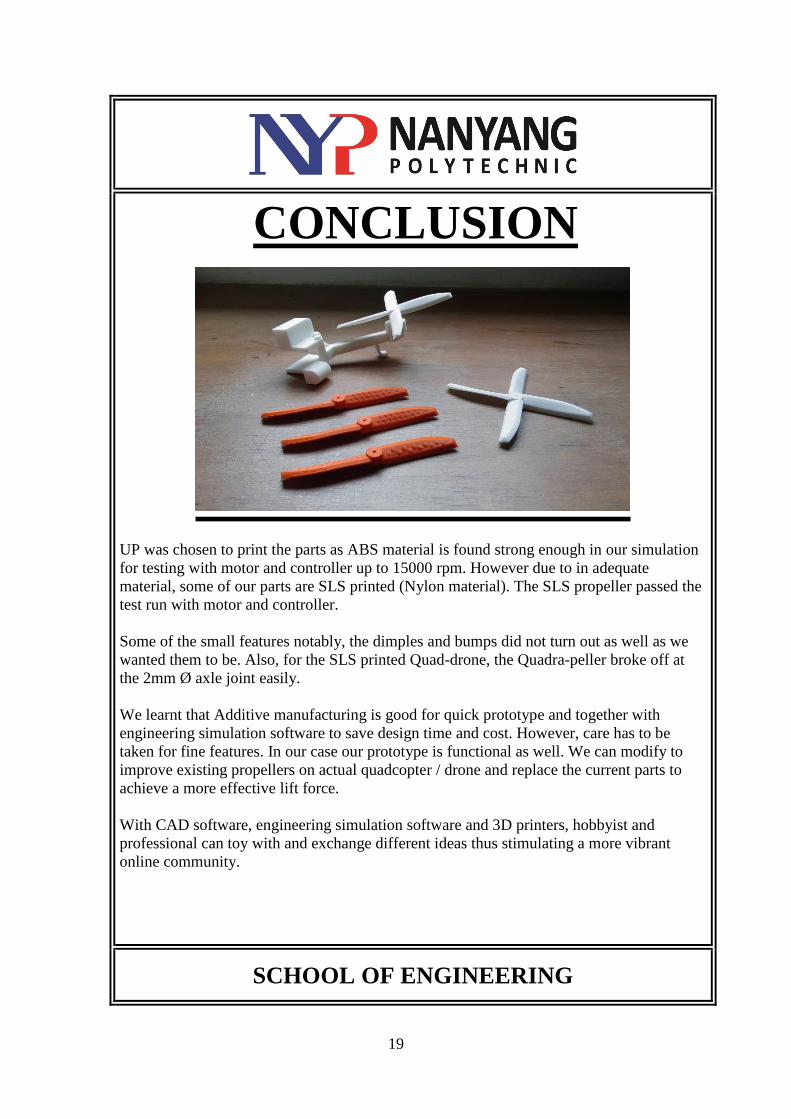
Fig 6.2 Test Fixture to secure above a simple weighing machine for measurement of Propeller trust force
Resonance occurs at 250 Hz (15000 rpm / 1570 rad/sec), thus recommended max motor
test speed not beyond 200 Hz (12000 rpm). Safety factor of 1.25
Fig 6.3 Propeller test run:
Click https://drive.google.com/open?id=0B-oWcpQpRgJdSWZIQkFTTHlfS0U
SCHOOL OF ENGINEERING
19
CONCLUSION
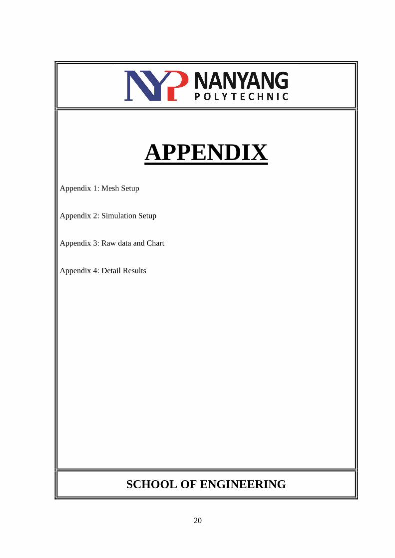
UP was chosen to print the parts as ABS material is found strong enough in our simulation
for testing with motor and controller up to 15000 rpm. However due to in adequate
material, some of our parts are SLS printed (Nylon material). The SLS propeller passed the
test run with motor and controller.
Some of the small features notably, the dimples and bumps did not turn out as well as we
wanted them to be. Also, for the SLS printed Quad-drone, the Quadra-peller broke off at
the 2mm Ø axle joint easily.
We learnt that Additive manufacturing is good for quick prototype and together with
engineering simulation software to save design time and cost. However, care has to be
taken for fine features. In our case our prototype is functional as well. We can modify to
improve existing propellers on actual quadcopter / drone and replace the current parts to
achieve a more effective lift force.
With CAD software, engineering simulation software and 3D printers, hobbyist and
professional can toy with and exchange different ideas thus stimulating a more vibrant
online community.
SCHOOL OF ENGINEERING
20
APPENDIX
Appendix 1: Mesh Setup
Appendix 2: Simulation Setup
Appendix 3: Raw data and Chart
Appendix 4: Detail Results
SCHOOL OF ENGINEERING
21
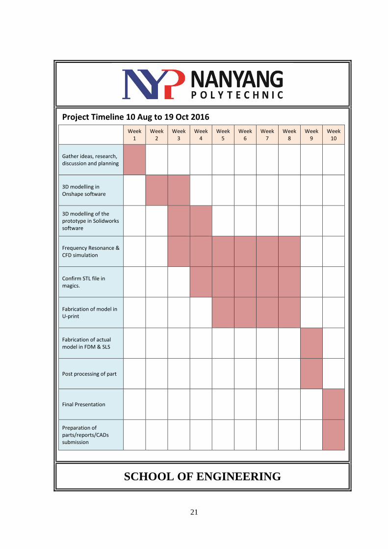
Project Timeline 10 Aug to 19 Oct 2016
Week 1
Week 2
Week 3
Week 4
Week 5
Week 6
Week 7
Week 8
Week 9
Week 10
Gather ideas, research, discussion and planning
3D modelling in Onshape software
3D modelling of the prototype in Solidworks software
Frequency Resonance & CFD simulation
Confirm STL file in magics.
Fabrication of model in U-print
Fabrication of actual model in FDM & SLS
Post processing of part
Final Presentation
Preparation of parts/reports/CADs submission
SCHOOL OF ENGINEERING
22
REFERENCES
1. Udemy, Engineering Simulation with SimScale: Drone Aerodynamics
https://www.udemy.com/engineering-simulation-with-simscale-drone-
aerodynamics
SCHOOL OF ENGINEERING