design optimization and analysis on flexible … · design optimization and analysis on flexible...
TRANSCRIPT
DESIGN OPTIMIZATION AND ANALYSIS ON FLEXIBLE
MANUFACTURING SYSTEM
MOHD KHAIRUL FADZLY BIN ABU BAKAR I
A thesis submitted in
fulfilment of the award of the
Degree of Master of Mechanical Engineering I
Faculty of Mechanical and Manufacturing Engineering
Universiti Tun Hussein Onn Malaysia
JULY 2013
CONTENTS
TITLE
DECLARATION
DEDICATION
ACKNOLEDGEMENT
CONTENTS
LIST OF TABLES
LIST OF FIGURES
LIST OF APPENDICES
ABSTRAK
ABSTRACT
CHAPTER 1: INTRODUCTION
1.1 Problem statement
1.2 Project introduction
1.3 Project objective
1.4 Project scope
1.5 Significian of the research
CHAPTER 2: LITERATURE REVIEW
2.1 Introduction
2.2 Simulation
2.2.1 Simulation process
2.2.2 Simulation benefits
2.2.3 Disadvantages of simulation
2.2.4 Future of simulation
2.2.5 Application Areas
2.2.5.1 Production and manufacturing
v
i
ii
iii
iv
v
viii
ix
xi
xii
xii
1
3
3
4
2.2.5.2 Other area
2.3 Arena
2.3 Overview of flexible manufacturing
system at automation and robotic laboratory universiti malaysia perlis
2.3.1 Automatic Material Handling System
2.3.2 Material Pallet
2.3.3 Material storage rack (ASRS)
2.3.4 ABB robots
2.3.5 Citect Scada System
2.3.6 Integrated system controller mitsubishi
programmable logic controller
CHAPTER 3: METHODOLOGY
3.1 Introduction
3.2 FMS layout design
3.2.1 FMS planning problems
3.2.2 FMS scheduling problems t
3.2.3 Using layout simulation as project methodology
3.3 FMS control problems
3.4 Introduction to simulation
3.5 Arena
3.5.1 Arena tools and features
3.5.2 Arena integration and customization
3.6 FMS modeling and simulation
3.7 Using arena simulation software to simulate FMS layout
3.8 Simulation structure
3.8.1 Entities
3.8.2 Attributes
3.8.3 Activity and events
3.8.4 Resources
3.8.5 Animation
3.8.6 Model development

3.8.7 Selection rule sub model
CHAPTER 4: RESULT AND ANALYSIS
CHAPTER 5: DISCUSSION AND CONCLUSSION
REFFERENCES
APPENDICES
LIST OF TABLES
1 Key Performance Indicator based on Cost
for all types of FMS Layout
2 Entity Detail Summary Time
for all types of FMS Layout
3 Entity Detail Summary Cost for
all types of FMS Layout
LIST OF FIGURES
Layout of FMS at Automation and Robotics
Laboratory UNIMAP
Four section of automatic material handling system for FMS
Material handling system for pallet
Pallet ID identification for FMS
Material storage rack for FMS
ABB robot for FMS
SCADA main screen for FMS. i
PLC unit for FMS
The life cycle of a simulation study by Balci (1990)
Entities for FMS Layout Simulation
Resource for FMS Layout Simulation
FMS Loop Layout Simulation
Animation of FMS Loop Layout Simulation
Key Performance indicator for FMS Loop Layout Simulation
Entity Detail Summary for FMS Loop Layout Simulation
FMS Ladder Layout Simulation
Animation of FMS Ladder Layout Simulation
Key Performance indicator for FMS Ladder Layout Simulation
ix
Entity Detail Summary for FMS Ladder Layout Simulation
FMS In-Line Layout Simulation
Animation of FMS In-Line Layout Simulation
Key Performance indicator for FMS In-Line Layout Simulation
Entity Detail Summary for FMS In-Line Layout Simulation
FMS Robot Centre Cell Layout Simulation
Animation of FMS Robot Centre Cell Layout Simulation I
Key Performance indicator for FMS Robot Centre Cell
Layout Simulation
Entity Detail Summary for FMS Robot Centre Cell
Layout Simulation
LIST OF APPENDICES
APPENDIX TITLE PAGE
A FMS Loop Layout Simulation Result I 5 8
B FMS Ladder Layout Simulation Result 6 1
C FMS In-Line Layout Simulation Result 64
D FMS Robot Centre Cell Layout Simulation Result 67
ABSTRAK
Sistem pembuatan fleksibel (FMS) adalah ditakrifkan sebagai kumpulan yang sangat
automatik teknologi sel mesin, yang terdiri daripada sekumpulan stesen pemprosesan I
saling oleh pengendalian bahan automatik dan sistem penyimpanan, dan dikawal oleh
sistem komputer bersepadu. FMS boleh menghasilkan bahagian atau produk pada
pertengahan kelantangan, pertengahan pelbagai pelbagai pengeluaran. Sistem susun atur
di FMS adalah satu kriteria penting untuk mereka bentuk sistem FMS untuk
menghasilkan bahagian atau produk. Ini susun atur kemudahan daripada FMS i
melibatkan kedudukan sel-sel dalam sempadan yang diberikan, untuk mengurangkan
masa perjalanan keseluruhan diunjurkan antara sel-sel. Penentuan susun atur
termasuklah penetapan koordinat spatial setiap sel, orientasi sama ada secara melintang
atau menegak, dan lokasi muatannya atau titik dipunggah. Terdapat banyak jenis susun
atur FMS seperti In-line, tangga gelung dan robot susun atur sel berpusat. Kajian ini
memberi tumpuan kepada reka bentuk dan pengoptimuman FMS susun atur.
Kesimpulan akhir boleh dirumuskan bahawa objektif untuk mereka bentuk dan
mengoptimumkan susun atur FMS untuk kajian ini adalah berjaya kerana FMS susun
atur dalam talian adalah susun atur yang terbaik berdasarkan masa yang berkesan dan
kos menggunakan perisian simulasi ARENA.
ABSTRACT
Flexible manufacturing system (FMS) was defined as highly automated group
technology machine cell, consisting of a group of processing stations interconnected by I
an automated material handling and storage system, and controlled by an integrated
computer system. FMS can produce parts or products are in the mid-volume, mid-
variety production range. The layout system in FMS is an importance criterion to design
the FMS system to produce a part or product. This facility layout of a FMS involves the
positioning of cells within given boundaries, so as to minimize the total projected travel i
time between cells. Defining the layout includes specifying the spatial coordinates of
each cell, its orientation in either a horizontal or vertical position, and the location of its
load or unloads point. There are many type of FMS layout such as In-line, loop ladder
and robot centered cell layout. The research is concentrate on design and optimization
FMS layout. The final conclusion can be summarized that the objective to design and
optimize of FMS layout for this study is successful because FMS In-line layout is the
best layout based on effective time and cost using ARENA simulation software.
CHAPTER 1
INTRODUCTION
A flexible manufacturing system (FMS) is an arrangement of machines
interconnected by a transport system. The transporter carries work to the machines I
on pallets or other interface units so that work-machine registration is accurate, rapid
and automatic. A central computer controls both machines and transport system.
FMS technology can be apply when the plant presently either produces parts in
batches or uses manned group technology cells and management wants to automate
the cells. It must be possible to group a portion of the parts made in the plant into C
part families and the part similarities allow them to be processed on the FMS
workstations. FMS can produce parts or products are in the mid-volume, mid-variety
production range.
For this project FMS for educational propose is to be study. Flexible
Manufacturing System (FMS) typically possesses multiple automated stations and is
capable of variable routings among stations. Human resource development,
equipment operator skills, manufacture of processing tools, products, processes &
machinery, research and development are some of the issues resulting from higher
level of technology implementation. Industry needs universities to respond with
increase emphasis on design and manufacturing skills. With FMS teaching and
training in the university laboratories, the increasing capability of engineers provides
a distinct advantage for future industries.
The FMS is technologically more sophisticated for the industries and the
human resources who must make it work. Flexible Manufacturing Systems (FMS), as
they were called, became a great focus of attention in industry and in academic
research for a number of years. The advantages of a well-run FMS were clear; short
lead-times, low inventory and a step towards the factory of the future.
Human resource development, equipment operator skills, manufacture of
processing tools, products, processes & machinery, research and development are
some of the issues resulting fiom higher level of technology implementation. In this 1
situation, a contingency strategy for training engineers and other specialists with
FMS should be considered in university learning with engineering education. These
evolving trends in industry must be applied back into the engineering curriculum.
Industry needs universities to respond with increase emphasis on design and
manufacturing skills. I
The Educational Flexible manufacturing system (FMS) is a actual-size of
automatic manufacturing system, which consist of a actual-size automatic storage
and retrieval system, a actual-size product line, robotic arm and some CNC machines
such as CNC milling machine and CNC lathe machine. The FMS is an open
architecture platform, suitable for teaching and training in the fields of automatic
control, CNC, manufacturing and mechatronics, robot system, material handling
technology, sensors and many more. The FMS is based on Industrial grade
components, design according to real industrial production and using most common
parts in industrial facilities. Manufacturing management needs to be equipped with new
and effective tools due to the rapidly changing and highly competitive nature of today's
global markets. New generation hardware and software, tailored into specific
applications are being developed each and everyday, however a success in reducing
costs, increasing efficiency and improving quality is not easy until an application based
integration of these components is attained. As mentioned by (Yiicel, 2004) "Modern
Flexible Manufacturing System (FMS) with a concrete system model design and the use
of information technologies answers these requirements".
1.1 Problem statement
The design and use of flexible manufacturing systems layouts involve some intricate
operations research problems. FMS design problems include, for example, I
determining the appropriate number of machine tools of each type, the capacity of
the material handling system, and the size of buffers. FMS planning problems
include the determination of which parts should be simultaneously machined, the
optimal partition of machine tools into groups, allocations of pallets and fixtures to
part types, and the assignment of operations and associfted cutting tools among the
limited-capacity tool magazines of the machine tools. FMS scheduling problems
include determining the optimal input sequence of parts and an optimal sequence at
each machine tool given the current part mix. FMS control problems are those
concerned is monitoring the system to be sure that requirements for storage and
retrival system for FMS.
1.2 Project introduction
The studies are concentrating on design layout of FMS and focus on monitoring and
control system for educational flexible manufacturing system (FMS). There are many
type of FMS layout such as In-line, loop ladder, open field and robot centered cell
layout. The research is based on design and optimization FMS layout. Every layouts
will be analyze using modeling software (Arena Simulation Software) to determine
the most practical layout for the FMS.
1.3 Project objective
Optimization of Flexible Manufacturing System (FMs). layouts for
educational purpose.
To simulate several FMS layouts using modeling software
To propose the most practical layout to be used. I
1.4 Project scope
Study about Flexible Manufacturing System for educational purpose and
focused on FMS's layout. I
Simulate the FMS layout using modeling software.
To analyze the FMS based on layout using modeling software and determine
the efficiency.
1.5 Significiance of the research
It is importance to study about Flexible Manufacturing System Layout using
modeling software to determine the practical layout to be use as a real system.
Through modeling software the setup cost for the real system can be reduced because
the most practical layout can be simply setup without wasting the time. From this
researce is shown that FMS In-Line layout is the best layout and practically be used
for FMS educational proposes at Universiti Malaysia Perlis
4
CHAPTER 2
LITERATURE REVIEW
2.1 Introduction
Flexible manufacturing systems (FMSs), being someWhat similar and yet
different from conventional manufacturing systems, provide new and different
problems and FMS have promised many benefits but there is evidence that the
implementation of FMS is often fraught with difficulty. One result is that the
implementation rate of FMS is much lower than has been expected. The aim of this
research is to review the approaches that can be usbd to design an FMS and
monitoring system. A review is given of the work done to date on the design of FMS
in the areas of facilities design, material handling system design, control system
design, and scheduling. Through examining the tools and approaches that are used to
design these four phases it is apparent that no integrated design methodology exists
for FMS. The tools available are not specifically tailored for FMS and their unique
integrated form. Because of the lack of integration, an FMS must be designed by
examining the four phases independently even though the design decisions from each
area affect the efficiency of the other areas.
The design process for FMS can be broken down into the following phases
such as facilities design - including the choice of machines and the layout of the
FMS, material handling system design, which includes the choice of the material
handling equipment and control system design - including the choice of the control
scheme and methodologies to be used.
2.2 Simulation
As defined by Robert E. Shannon (1975) "The process of designing a model of a
real or imaginary system and conducting experiments with this model for the purpose
either of understanding the behavior of the system or of evaluating various strategies I
(within the limits imposed by a criterion or set of criteria) for the operation of the
system." The first sentence of the definition mentions the types of systems that
simulation studies can be conducted on. The systems can be "real" or "imaginary",
which means that there can exist a physical facility or a process to be modeled, or the
model can be a modification of the existing system or it can be totally imaginary. I
The imaginary systems refer to the ones that are planned as alternatives to existing
systems and entirely original systems.
2.11 Simulation process
As Shannon states simulation is a continuous "process" rather than a one time create-
and-use application. Especially computer simulation is an iterative method that
includes several stages as Kelton et al (2004) identifies. A simulation study starts
with efforts on understanding the system in addition with the identification of the
goals of the study. The next step is creating the formulation of the model
representation usually in terms of mathematical models or flowcharts. Subsequently,
the created formulation needs to be transferred into modeling software using
programming languages or with specific software tailored into the needs of a
6
simulation study. Once a program is created, it is necessary to verify the program, in
the sense that right things occur with expected inputs. The following stage is to
validate the program with someone familiar to the represented system so that the
program works in accordance with the conceptual model faithfully, supporting the
validation work with statistical tests can be of critical importance at this stage.
Experimentation on the developed model is the following phase, which includes
designing experiments to identify the critical performance measures to be used with
adequate confidence and running these designed experiments by using the computers I
effectively. The last stages take account of analyzing the results, getting insight of
the results to evaluate the outcomes of the results and to assess the potential benefits.
Finally, documentation is necessary for the inheritance of the work done for other
simulation staff and also to clearly transfer the findings and recommendations to
related management levels with precision and confidence. i
The life cycle of a simulation study has also been identified in detail by Balci
(1990). This life cycle has been divided into 10 processes, 10 phases and 13
credibility assessment stages. Figure 9 provides the details of those identifications
and the precedence and succession relations between them. All those stages
mentioned seem troublesome and time consuming, however success in simulation is
difficult to attain without following these steps. It is necessary to identify what
success is at this stage. According to (Sadowski 1999) a successful simulation project
is the one that delivers useful information at the appropriate time to support a
meaningful decision, which implies that there are three key elements of success in
simulation; decision, timing and information.
2.1.2 Simulation benefits
Simulation has many benefits for the users as outlined by J. Banks (2000). First of
all, it lets users choose correctly among the possible alternatives, provides time
compression and expansion according to the type of the simulated event, equips the
managers with the tools to understand "why?" certain phenomena *occur in a real
system, allows the user to explore possibilities of new policies, operating procedures
or methods. With simulation, one can diagnose problems of complex systems that are
almost impossible to deal within the real environment, identi& constraints that act as
a bottleneck for operations, visualize the plan using the animation capabilities of the
s o h a r e used that results in a more presentable design. Simulation is also beneficial
to build consensus among the members of the decision makers and to prepare for
changes by considering the possible "what if' scenarios. Virtual Reality (VR)
support creates training environments for production team, it can also be used to
specify requirements for capabilities of equipment and carry out wise investments
using all those properties.
2.1.3 Disadvantages of Simulation
There are things one should consider carefully on carrying out simulation studies. It
is a probability that simulation may not be the perfect tool for all types of system
analysis. Banks (2000) underlines four main disadvantages of simulation. The first
disadvantage is that model building requires special training and it is highly unlikely
that models generated by different modelers about the same system will be the same.
The second disadvantage is about the simulation results' being difficult to interpret.
As most simulation outputs are essentially random variables based on random inputs,
8
it may be hard to determine whether an observation is a result of system
interrelationships or randomness. The third disadvantage is that simulation modeling
and analysis can be time consuming and expensive especially when enough resource
is not allocated for modeling and analysis, resulting in a simulation model andlor
analysis that are not sufficient to the task. A final disadvantage is that simulation may
be used inappropriately, especially in some cases when an analytical solution is
possible or even preferable.
I
2.1.4 Future of Simulation
The future of simulation is believed to be different from the past. According to J.
Carson and D. Brunner (2000) there will be an increase in simulation becoming
embedded in other larger software applications and simulation will be more widely
used for real-time decision making rather than the tradi~onal off-line methods. The
general literature suggests that the interoperability of simulation software with other
software is crucial. The data formats of the simulation software used to model and
predict the behavior of manufacturing systems and the applications about design,
manufacturing engineering, and production management need to be the same.
Neutral interface specifications that would permit quick and easy integration of
commercial off-the-shelf software should be developed.
One other important prediction about the future of the simulation is about the
development of new simulation interface standards that would help the deployment
of simulation technology. Currently, the simulation model development process is
labor intensive, perhaps more of an art than science, an approach that leaves
considerable work and creative responsibility to the simulation analyst.

One of the promising ideas for expanding simulation to a broader set of users
is the concept of having pre-built models or model components that can be plugged
together to form a model of the system to be modeled. The idea is to select the
components from a library and use them directly. The goal is to build each model
component once, verify its operation, and the make it available in a library to be used
in many different applications.
2.1.5 Application Areas I
Simulation has found a great deal of application areas both in the academic and
industrial fields of work. The field of application of simulation includes but is not
limited to manufacturing facilities, bank or similar other personal-service operations,
transportation, logistics and distribution operation, hospital facilities, computer
network, fieeway system, business process, criminal justice system, chemical plants,
fast-food restaurants, supermarkets, theme parks, emergency response systems, etc.
The following sections give examples from the literature about several applications
of simulation. The topic is studied under two main headings, dividing the
applications as manufacturing and production and others. Although this study is in
the field of manufacturing and production, other applications in different fields
provide insight for different aspects of simulation.
2.1.5.1 Production and Manufacturing
One of the largest application areas for simulation modeling is that of manufacturing
systems, with the first uses dating back to at least the early 1960's. Since then, it has
been used effectively in the design and analysis of manufacturing systems. Law
10
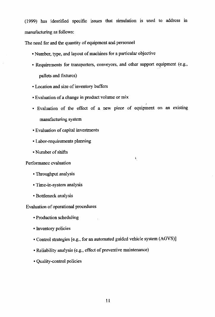
(1999) has identified specific issues that simulation is used to address in
manufacturing as follows:
The need for and the quantity of equipment and personnel
Number, type, and layout of machines for a particular objective
Requirements for transporters, conveyors, and other support equipment (e.g.,
pallets and fixtures)
Location and size of inventory buffers
Evaluation of a change in product volume or mix I
Evaluation of the effect of a new piece of equipment on an existing
manufacturing system
Evaluation of capital investments
Labor-requirements planning
Number of shifts
Performance evaluation
Throughput analysis
Time-in-system analysis
Bottleneck analysis
Evaluation of operational procedures
Production scheduling
Inventory policies
Control strategies [e.g., for an automated guided vehicle system (AGVS)]
Reliability analysis (e.g., effect of preventive maintenance)
Quality-control policies
As seen from the above discussion, manufacturing and production offers a
huge number of issues to deal with. Some of the recent applications of simulation
and modeling in this area are given below. It should be noted that there are thousands
of studies in this field, but the following are important as they mostly make examples
@ of using ARENA in simulation.
The work of Williams (2002) is important as it presents the usefulness of
simulation in studying the impacts of system failures and delays on the output and
cycle time of finished parts. Also, the similarity of the robotic work cell used as the I
modeling medium to our environment is worth mentioning. The case study illustrates
a modeling approach with system verification and validation revealing fwndamental
system design flaws.
Pate1 et a1 (2002) have used discrete event simulation for analyzing the issues
of first time success rate, repair and service routing logic, process layout, operator I
staffing, capacity of testing equipment and random equipment breakdown in
automobile manufacturing processes. They offer concepts and methods for discrete
manufacturing processes especially for the Final Process System for optimizing
resources and identifying constraints.
The studies in literature include the auxiliary programs for simulation, as
@ well. Rogers (2002) has used OptQuest for ARENA for applying optimum-seeking
simulation tools to manufacturing system design and control problems. The author
describes the software as a tool that can be broadly applied to find optimal values of
controllable parameters for systems being analyzed via simulation.
Altinkilic (2004) has presented a use of simulation to improve shop floor
performance. The performance of the existing system is evaluated by using
@ ARENA . Due to the motivation for redesigning the shop flow, manufacturing cells
are performed and the performance of the new system is evaluated and compared
with that of the current system. As a result, based on a simulation analysis, several
recommendations are made to the management of the mentioned job shop production
system.
2.1.5.2 Other Areas
The example studies given below provide a reflection of the usage areas of I
simulation apart from manufacturing and production, and of typical results those can
be attained. It is known for sure that both the number and range of the point at issue
is almost unlimited, but these studies are important to provide a basic understanding
of simulation applications.
Chen (2002) has used simulation to come up with an application to provide a i
critical decision support tool in a chemical plant for logistics activities. Using the
simulation model, the authors have determined capital equipment requirements and
assessed alternative strategies for logistics operations, such as the number and size of
storage silos for the chemical plant. Although the authors do not propose a new
concept, the object oriented approach they have used and their discrete event model
to simulate continuous production flow is worth mentioning.
One of the mentioned application areas was policy. Simulation has been
widely used to help public policy makers evaluate decisions on subjects such as
traffic, emergency planning and health management. An application of simulation
involves the discussion of traffic management for Istanbul district and advises on the
future of the city taking marine traffic into consideration (Kose 2003). Land traffic
and air traffic has also been subject to individual symposiums and editorials in
several journals.
In their studies Hill (2001) and Standridge (1999) have studied the
applications of simulation in the fields of military problems and health care
applications, respectively. Both studies address wide ranging issues in their
respective areas with sample applications to come up with invaluable comments and
results about simulation studies in general. Graves and Higgins (2002) has combined
logistics and military requirements in a single simulation study. With the applications
described in the study, the potential impact that simulation can have on army
logistical systems have been illustrated in the fields of supply, transportation and
maintenance.
The work of Nsakanda and Turcotte (2004) illustrates the use of simulation
for evaluating and analyzing air cargo operations at one of the new state-of-the-art i
cargo facilities at Toronto Pearson Airport. A brief description of the airline's cargo
operations has been described as well as the simulation modeling approach. They
have showed that the simulation-based tool they have proposed could be effectively
used in its current level of development to quantitatively evaluate and compare
different policies, business practices and procedures within a given set of operational
and business constraints.
Q 2.2 ARENA
@ The ARENA modeling system from Systems Modeling Corporation is a flexible
and powerful tool that allows analysts to create animated simulation models that
Q accurately represent virtually any system. First released in 1993, ARENA employs
an object-oriented design for entirely graphical model development. Simulation
analysts place graphical objects, called modules, on a layout in order to define
system components such as machines, operators, and material handling devices.
@ ARENA is built on the SIMAN simulation language. After creating a simulation
@ model graphically, ARENA automatically generates the underlying SIMAN model
used to perform simulation runs (Takus, 1997). This brief description provided by a
senior software developer of the program owning company, emphasizes the graphical
Q interface, and ease of programming that arises as a result. The ARENA product
suite is designed for use throughout an enterprise, from strategic business decisions,
such as locating capacity in a supply chain planning initiative, down to operational
planning improvements, such as establishing production line operating rates (Bapat,
2000). To achieve enterprise wide top-down scalability and ease of use by all levels
@ of an enterprise, ARENA has many unique properties, hhich are described in brief
@ below. ARENA has a natural and consistent modeling methodology due to its
flowchart style model building regardless of detail or complexity. Even the
@ flowcharts of systems created by Microsoft Visio can be imported and used directly.
It is extendable and customizable, which results in a re-creatable, reusable and
distributable templates tailored to specific applications. The scalable architecture of
Q ARENA provides a modeling medium that is easy enough to suit the needs of the
beginner, and powerful enough to satisfy the demands of the most advanced users.
This makes it a perfect tool for continuously improving modeling studies as the
modeler's capability and experience increase as the study progresses. One other
Q advantage of ARENA is that it is open to interaction with many applications such as
Microsoft Access and Excel with its built-in spreadsheet data interface. Furthermore,
@ with Visual Basic for Applications (VBA ) support there is virtually no limit on
@ creating interfaces and programs. With those mentioned advantages ARENA has
become the academic standard, which is thought in most Industrial Engineering
schools worldwide, which also encouraged the Integrated Manufacturing
Technologies Research Group to obtain an academic license of the program.
2.3 Overview of Flexible Manufacturing System at Automation and Robotic
laboratory Universiti Malaysia Perlis I
Definition according to the Computer and Automated Systems Association of the
Society of Manufacturing Engineers: "CIM is the integration of total manufacturing
enterprise by using integrated systems and data communication coupled with new
managerial philosophies that improve organizational and personnel efficiency."
Accordingly the CAD/CAM technology, related to the 2se of computer systems for
design and production, was developed. CAD (computeraided design) was created to
assist in the creation, modification, analysis, and optimization of design. CAM
(computer-aided manufacturing) was designed to help with the planning, control, and
management of production operations. CADICAM technology, since the 1970s, has
been applied in many industries, including machined components, electronics
products, equipment design and fabrication for chemical processing. Total CIM
systems can handle order entry, cost accounting, customer billing and employee time
records and payroll. The scope of CIM technology includes all activities that are
concerned with production. Therefore in many ways CIM represents the highest level
of automation in manufacturing. UNIMAP CIM system consists of an computer
integrated manufacturing system with the following major components such as an
automatic material handling system as material transportation and tracking module,
16
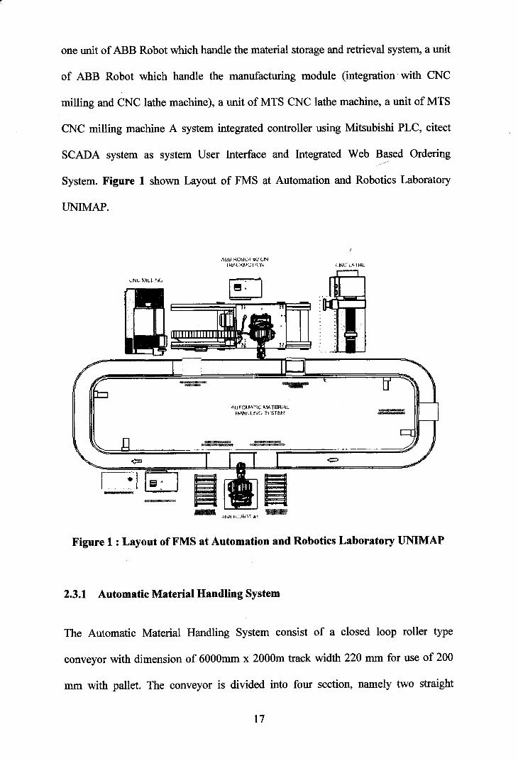
one unit of ABB Robot which handle the material storage and retrieval system, a unit
of ABB Robot which handle the manufacturing module (integration with CNC
milling and CNC lathe machine), a unit of MTS CNC lathe machine, a unit of MTS
CNC milling machine A system integrated controller using Mitsubishi PLC, citect
SCADA system as system User Interface and Integrated Web Based Ordering
System. Figure 1 shown Layout of FMS at Automation and Robotics Laboratory
UNIMAP.
Figure 1 : Layout of FMS at Automation and Robotics Laboratory UNIMAP
2.3.1 Automatic Material Handling System
The Automatic Material Handling System consist of a closed loop roller type
conveyor with dimension of 6000mm x 2000m track width 220 mrn for use of 200
mrn with pallet. The conveyor is divided into four section, namely two straight
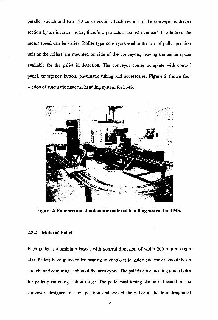
parallel stretch and two 180 curve section. Each section of the conveyor is driven
section by an inverter motor, therefore protected against overload. In addition, the
motor speed can be varies. Roller type conveyors enable the use of pallet position
unit as the rollers are mounted on side of the conveyors, leaving the center space
available for the pallet id detection. The conveyor comes complete with control
panel, emergency button, pneumatic tubing and accessories. Figure 2 shown four
section of automatic material handling system for FMS.
Figure 2: Four section of automatic material handling system for FMS.
2.3.2 Material Pallet
Each pallet is aluminium based, with general dimesion of width 200 mrn x length
200. Pallets have guide roller bearing to enable it to guide and move smoothly on
straight and cornering section of the conveyors. The pallets have locating guide holes
for pallet positioning station usage. The pallet positioning station is located on the
conveyor, designed to stop, position and locked the pallet at the four designated
18
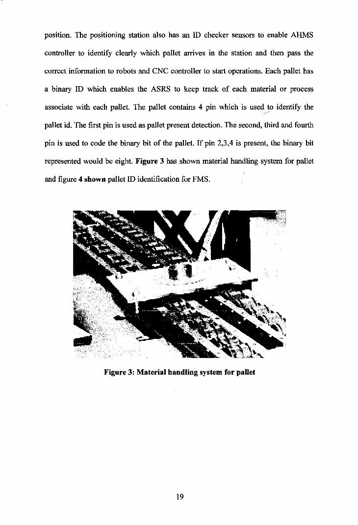
position. The positioning station also has an ID checker sensors to enable AHMS
controller to identify clearly which pallet arrives in the station and then pass the
correct information to robots and CNC controller to start operations. Each pallet has
a binary ID which enables the ASRS to keep track of each material or process
associate with each pallet. The pallet contains 4 pin which is used to identifjr the
pallet id. The first pin is used as pallet present detection. The second, third and fourth
pin is used to code the binary bit of the pallet. If pin 2,3,4 is present, the binary bit
represented would be eight. Figure 3 has shown material handling system for pallet I
and figure 4 shown pallet ID identification for FMS.
Figure 3: Material handling system for pallet
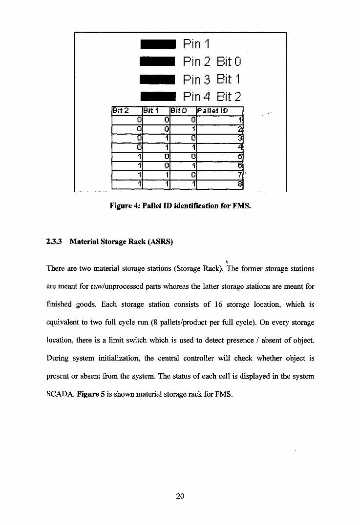
Pin 1 Pin 2 Bit O Pin 3 Bit 1 Pin4 Bit 2
Figure 4: Pallet ID identification for FMS.
2.3.3 Material Storage Rack (ASRS)
I
There are two material storage stations (Storage Rack). The former storage stations
are meant for raw/unprocessed parts whereas the latter storage stations are meant for
finished goods. Each storage station consists of 16 storage location, which is
equivalent to two full cycle run (8 pallets/product per full cycle). On every storage
location, there is a limit switch which is used to detect presence / absent of object.
During system initialization, the central controller will check whether object is
present or absent from the system. The status of each cell is displayed in the system
SCADA. Figure 5 is shown material storage rack for FMS.
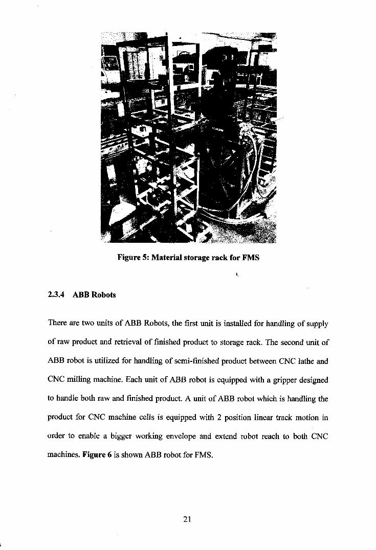
Figure 5: Material storage rack for FMS
h
2.3.4 ABB Robots
There are two units of ABB Robots, the first unit is installed for handling of supply
of raw product and retrieval of finished product to storage rack. The second unit of
ABB robot is utilized for handling of semi-finished product between CNC lathe and
CNC milling machine. Each unit of ABB robot is equipped with a gripper designed
to handle both raw and finished product. A unit of ABB robot which is handling the
product for CNC machine cells is equipped with 2 position linear track motion in
order to enable a bigger working envelope and extend robot reach to both CNC
machines. Figure 6 is shown ABB robot for FMS.
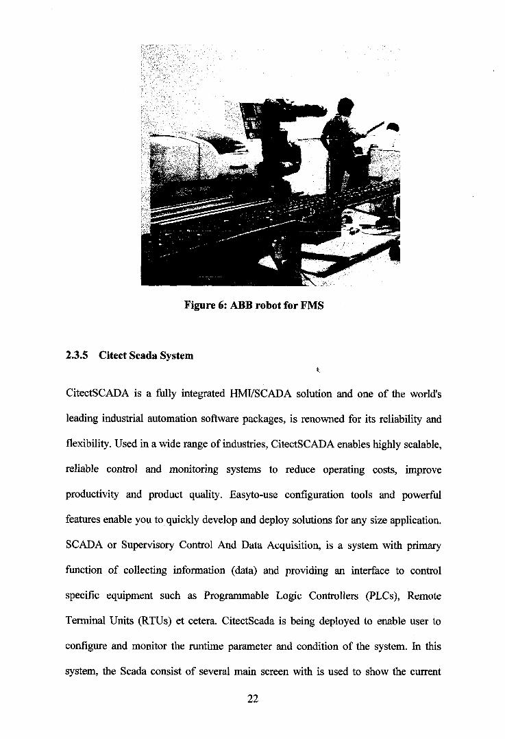
Figure 6: ABB robot for FMS
2.3.5 Citect Scada System C
CitectSCADA is a fully integrated HMVSCADA solution and one of the world's
leading industrial automation software packages, is renowned for its reliability and
flexibility. Used in a wide range of industries, CitectSCADA enables highly scalable,
reliable control and monitoring systems to reduce operating costs, improve
productivity and product quality. Easyto-use configuration tools and powerful
features enable you to quickly develop and deploy solutions for any size application.
SCADA or Supervisory Control And Data Acquisition, is a system with primary
function of collecting information (data) and providing an interface to control
specific equipment such as Programmable Logic Controllers (PLCs), Remote
Terminal Units (RTUs) et cetera. CitectScada is being deployed to enable user to
configure and monitor the runtime parameter and condition of the system. In this
system, the Scada consist of several main screen with is used to show the current
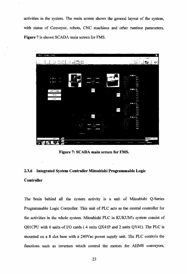
activities in the system. The main screen shows the general layout of the system,
with status of Conveyor, robots, CNC machines and other runtime parameters.
Figure 7 is shown SCADA main screen for FMS.
Figure 7: SCADA main screen for FMS.
2.3.6 Integrated System Controller Mitsubishi Programmable Logic
Controller
The brain behind all the system activity is a unit of Mitsubishi Q-Series
Programmable Logic Controller. This unit of PLC acts as the central controller for
the activities in the whole system. Mitsubishi PLC in KUKUM's system consist of
QO 1 CPU with 6 units of 110 cards ( 4 units QX4 1P and 2 units QY4 1). The PLC is
mounted on a 8 slot base with a 240Vac power supply unit. The PLC controls the
functions such as inverters which control the motors for AHMS conveyors,
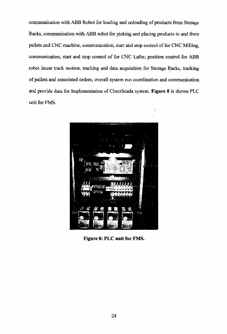
communication with ABB Robot for loading and unloading of products from Storage
Racks, communication with ABB robot for picking and placing products to and fkom
pallets and CNC machine, communication, start and stop control of for CNC Milling,
communication, start and stop control of for CNC Lathe, position control for ABB
robot linear track motion, tracking and data acquisition for Storage Racks, tracking
of pallets and associated orders, overall system run coordination and communication
and provide data for Implementation of CitectScada system. Figure 8 is shown PLC
unit for FMS. 1
Figure 8: PLC unit for FMS.
REFFERENCES
Altinkilic, M., (2004), "Simulation-based layout planning of a production plant",
Proceedings of the 2004 Winter Simulation Conference, pp 1079-1084
Balci, O., (1990), "Guidelines for successful simulation studies", Proceedings of the
1990 Winter Simulation Conference, pp 25-32.
Banks, J., (2000), "Introduction to simulation", ~ roceed in~ i of the 2000 Winter
Simulation Conference, pp 9- 16. Q
Bapat,V., Swets, N., "The Arena product family: enterprise modeling solutions",
Proceedings of the 2000 Winter Simulation Conference ,2000, pp 163- 1 69.
Chen, J.E., Lee, Y.M., Selikson, P.L.(2002), "A simulation study of logistics
activities in a chemical plant", Simulation Modelling Practice and Theory,
V01.10, No.3-4, pp 235-245. i
Graves, G. H., Higgins, J. L., (2002), 7'Applications of simulation in logistics combat
developments", Proceedings of the 2002 Winter Simulation Conference, pp
Hill, R. R., Miller, J. O., McIntyre, G. A., (2001), "Applications of discrete event
simulation modeling to military problems", Proceedings of the 2001 Winter
Simulation Conference, pp 780-788
Kelton, W. D. , Sadowski R.P., and Sturnock, D. T., (2004), Simulation with Arena, rd
3 International Edition, McGraw - Hill, New York
Kose,E., Basar, E., Demirci, E., Giineroglu A, Erkebay, $., (2003), "Simulation of
marine traffic in Istanbul Strait", Simulation Modelling Practice and Theory,
Vol. 1 1, No.7-8, pp 597-608.
Law, A.M., McComas, M.G.,(1999) "Simulation of manufacturing systems",
Proceedings of the 1999 Winter Simulation Conference, pp 56-59.
Luggen, W. W,, 1991, Flexible Manufacturing Cells and Systems, Prentice Hall, p.
19-378
Nsakanda, A. L., Turcotte, M., (2004), "Air cargo operations evaluation and analysis
through simulation", Proceedings of the 2004 Winter Simulation Conference,
pp 1790-1798
Patel, V., Ashby, J., Ma, J., (2002) "Discrete event simulation in automotive final
process system", Proceedings of the 2002 Winter Simulation Conference, pp
1030-1034.
Rogers, P., (2002), "Optimum-seeking simulation in the design and control of
manufacturing systems: experience with OptQuest for ARENA", Proceedings
of the 2002 Winter Simulation Conference, pp 1 142-1 150.
Sadowski, D. A., Grabau, M. R.,(1999), "Tips for successful practice of simulation",
Proceedings of the 1999 Winter Simulation Conference, pp 60-66
Shannon, R.E. (1975), "Systems Simulation: The Art and science", Prentice-Hall.
Standridge, C. R., (1999), "A tutorial on simulation in health care: Applications and
issues", Proceedings of the 1999 Winter Simulation Conference, pp 49-55
Stecke, K.E. (1 98 I), "Production planning problems for flexible manufacturing
Systems", Ph.D. Dissertation, Purdue University, West Lafayette, 198 1. Q
Takus, D.A, Profozich, D.M., "Arena software tutorial", Proceedings of the 1997 I
Winter Simulation Conference , Sewickley, Pennsylvania, USA, 1997, pp
54 1-543.
Van Looveren, A.J., Gelders, L.F. and Van Wassenhove, L.N., A review of FMS
planning models in modeling and design of FMS, edited by A. Kusiak, pp3-
3 1, Elsevier, Amsterdam, 1986
Williams, C.R., Chompuming, P., (2002) "A simulation study of robotic welding
system with parallel and serial processes in the metal fabrication industry",
Proceedings of the 2002 Winter Simulation Conference, pp 10 1 8- 1 025.
Yiicel, N.D., $en, D.T., &hq, S.E., (2004), "Integrating an agent based flexible
manufacturing cell framework with simulation: A pilot implementation",
Proceedings of The Eleventh International Conference on Machine Design
and Production, pp 653-662