design of pressure vessel
TRANSCRIPT

DESIGN OF PRESSURE VESSEL

PROJECT REPORT
Submitted by\
MIJO JOSEPH

VIPIN .M
VISHNU
VIJAY
ABSTRACT
This project work deals with a detailed study and design procedure of pressure
vessel. A detailed study of various parts of pressure vessels like shell, closure,
support, flanges, nozzles etc. Design is carried according to rules of ASME code
section VIII, Division I.
The first chapter deals with detailed study of pressure vessel i.e. the various materials
used in pressure construction and temperature are mentioned .It also deals with the
study of various parts like flanges, support etc. Various methods of fabrication and
testing are also included.
The second chapter includes design criteria .This is followed by procedure of design,
which include design shell and its components, nozzles, reinforcements etc.
LIST OF FIGURES
FIGURE PAGE

3.9.1 TYPES OF FLANGES 14
3.11.1 TYPES OF SKIRT 17
MODEL OF AMINE ABSORBER 29
5.1 TOP AND BOTTOM HEAD 32
5.2.1 TOP SECTION OF SHELL 35
5.2.2 BOTTOM SECTION OF SHELL 36
5.3 DESIGN OF NOZZLE 59
5.4 DESIGN OF REINFORCEMENT AREAS 72
LIST OF TABLES
DESIGN DATA 28
7 RESULT AND DISCUSSION 87

NOMENCLATURE
T : design temperature, °C
C : corrosion allowance, mm
Di : inside diameter of the vessel, mm
Do : outside diameter of the vessel, mm
Ri : inside radius of the vessel, mm
Ro : outside radius of the vessel, mm
S : maximum allowable stress, kg/cmA2
E : Joint efficiency, %
T : required the thickness, mm
tn : minimum thickness provided for the nozzle, mm
5

P : design pressure, kg/cmA2
trn : selected thickness for the nozzle, mm
fr : strength reduction factor
Mt : moment at the skirt to head joint, kg-mm W :
weight of the vessel H : height of center of gravity
Fe : seismic coefficient
N : Number of bolts
Ab : area with in the bolt circles, mmA2
Cb : circumference of bolt circle, mm
Ba : required area of one bolt, mm
As : area within the skirt, mmA2
Cs : circumference on outer diameter of skirt, mm
6

Dso outer diameter of the skirt, mm
7

P : design pressure, kg/cmA2
Dsi: inside diameter of the skirt, mm
Fb : safe bearing load on the concrete, kg/cmA2
I : width of the base plate, mm
The equations may be written in the following forms
t = PRi/(SE-0.6P) = Pro / (SE-0.4P)
t = minimum required thickness of the shell exclusively of
Corrosion allowance
8
Where, t

P= design pressure, or maximum an allowable working
9

Pressure
welded -joint efficiency
10

S maximum allowable stress
11

Ri inside radius of the shell
12

Ro=outside radius of the shell

If the thickness of the Shell exceeds 50% of the inside radius, or when the
pressure exceeds 0.385SE, the lame equation should be used to calculate the vessel-
shell thickness. The following forms of the lame equation are given by the code.
With the pressure p known.
t = Ri(Vz-l) = Ro (Vz-1)/Vz
Where, z = S.E+P/(S.E-P)
The equation for ellipsoidal head thickness is given by
t = PDi/ (2SE+0.2P) =PDo/ (2SE+1.8P) Where, t = minimum
required thickness of the ellipsoidal head exclusive of corrosion
allowance
P = design pressure, or maximum allowable working pressure.
E = welded - joint efficiency.
S = Maximum allowable stress.
Di = inside diameter of the shell
Do=outside diameter of the shell
CHAPTER
. 1
14

INTRODU
CTION
Chemical engineering involves the application of sciences to the process industries,
which are primarily concerned, with the conversion of one material into another by
ahemical or physical means. These processes require the handling or storing of large
quantities of materials in containers of varied constructions, depending upon the
existing state of the material, it's physical and chemical properties and the required
operations, which are to be performed. For handling such liquids and gases, a
container or vessel is used. It is called a pressure vessel, when they are containers for
fluids subjected to pressure. They are leak proof containers. They may be of any shape
ranging from types of processing equipment. Most process equipment units may be
considered as vessels with various modifications necessary to enable the units to
perform certain required functions, e.g. an autoclave may be considered as high-
pressure vessel equipped with agitation and heating sources.
Pressure vessels are in accordance with ASME code. The code gives for thickness
and stress of basic components, it is up to the designer to select appropriate analytical
as procedure for determining stress due to other loadings. The designer must
familiarize himself with the various types of stresses and loadings in order to
accurately apply the results of analysis. Designer must also consider some adequate
stress or failure theory in order to confine stress and set allowable stress limits.
15

The methods of design are primarily based on elastic analysis. There are also
other criteria such as stresses in plastic region, fatigue, creep, etc. which need
consideration in certain cases. Elastic analysis is developed on the assumption that the
material is isotropic and homogeneous and that it is loaded in the elastic region. This
analysis is not applicable in the plastic range. Under cyclic variation of load causing
plastic flow, the material to hardens and the behavior of material becomes purely
elastic. This is a phenomenon called shakedown or cessation of plastic deformation
under cyclic loading.
Elastic analysis is therefore in most important method of designing pressure
vessel shells and components beyond the elastic limit, the material yields and the
plastic region (spreads with increased value of load. The load for which this occurs is
called collapse load rusting pressure.
Limit analysis is concerned with calculating the load or pressure at which flow of
jfitructure material occurs due to yielding. However, this method is not usually applied
to Resign of pressure vessels. When vessels are subjected to cyclic loading, it is
necessary to consider requirements for elastic cycling of the material and the effects of
this on component behavior. In the case of a discontinuity of shape, load may give rise
to plastic cycling. Under these conditions, shakedown with occur. Maximum
shakedown load is twice the first yield load. Therefore, an elastic analysis is valid up
to the range of load, under cyclic loading conditions. A factor of safety on the stress or
a factor of safety of twenty is applied on the numbers cycles. Design stress is accepted
as the lower value.
16
CHAPTER.2 SCOPE
OF THE PROJECT
--In sophisticated pressure vessels encountered in engineering construction; high
pressure, extremes of temperature and severity of functional performance
requirements pose exciting design problems. The word "DESIGN" does not mean
only the calculation of the detailed dimensions of a member, but rather is an all-
inclusive term, incorporating:
1. The reasoning that established the most likely mode of damage or failure;
2. The method of stress analysis employed and significance of
results;
... 3. The selection of materials type and its environmental behaviour.
I The ever-increasing use of vessel has given special emphasis to analytical and
experimental methods for determining their emphasis to analytical and experimental
methods for determining their operating stresses. Of equal importance is the
appraising the significance of these stresses. This appraisal entails the means of
determining the values and extent of the stresses and strains, establishing the
behaviour of the material ■involved, and evaluating the compatibility of these two
factors in the media or environment to which they are subjected. Knowledge of
material behaviour is required not only to avoid failures, but also equally to permit
maximum economy of material choice and amount used.
CHAPTER.3
17

■
DESIGN CRITERIA
3.1 FACTORS INFLUENCING THE DESIGN
[Regardless of the nature of application of the vessels, a number of factors usually
must be considered in designing the unit. The most important consideration often is
the selection of the type of vessel that performs the required services in the most
satisfactory manner. In developing the design, a number of other criteria must be
considered such as the properties of material used, the induced stresses, the elastic
stability, and the aesthetic appearance of the unit. The cost of fabricated vessel is also
important in relation to its service and useful life.
3.2 DESIGN OF PRESSURE VESSELS TO CODE SPECIFICATION
American, Indian, British, Japanese, German and many other codes are available
for design of pressure vessels. However the internationally accepted for design of
pressure vessel code is American Society of Mechanical Engineering (ASME).
Various codes governing the procedures for the design, fabrication, inspection,
testing and operation of pressure vessels have been developed; partly as safety
measure. These procedures furnish standards by which, any state can be assured of the
safety of pressure vessels installed within its boundaries. The code used for unfired
pressure vessels is Section VIII of the ASME boiler and pressure vessel code. It is
usually necessary that the pressure vessel equipment be designed to a specific code in
18

order to obtain insurance on the plant in which the vessel is to be used. Regardless of
the method of design, pressure vessels with in the limits of the ASME code
specification are usually checked against these specifications.
3.3 DEVELOPMENT AND SCOPE OF ASME CODE
In 1911, American Society of Mechanical Engineering established a committee to
formulate standard specifications for the construction of steam boilers and other
pressure vessels. This committee reviewed the existing Massachusetts and Ohio rules
and eonducted an extensive survey among superintendents of inspection departments,
Engineers, fabricators, and boiler operators. A number of preliminary reports were
issued and revised. A final draft was prepared in 1914 and was approved as a code and
copy righted in 1915.
The introduction to the code stated that public hearings on the code should be held
every two years. In 1918, a revised edition of the ASME code was issued. In 1924, the
code was revised with the addition of a new section VIII, which represented a new
code for unfired pressure vessels.
3.4 THE API-ASME CODE
In 1931, a joint API-ASME committee on unfired pressure vessels was appointed
to prepare a code for safe practice in the design, construction, inspection and repair of
unfired pressure vessels.
3.5 SELECTION OF THE TYPE OF VESSEL
19

The first step in the design of any vessel is the selection of the type best suited for
the particular service in question. The primary factors influencing this choice are,
. i. The operating temperature and pressure.
ii. Function and location of the vessel.
iii. Nature of fluid.
■ iv. Necessary volume for storage or capacity for processing.
It is possible to indicate some generalities in the existing uses of the common
types of vessels. For storage of fluids at atmospheric pressure, cylindrical tanks with
flat bottoms and conical roofs commonly used. Spheres or spheroids are employed for
pressure storage where the volume required is large. For smaller volume under
pressure, cylindrical tanks with formed heads are more economical.
3.6 TYPES OF PRESSURE VESSELS
3.6.1 OPEN VESSELS
Open vessels are commonly used as surge tanks between operations, as vats for
batch operations where materials be mixed and blended as setting tanks, decarters,
chemical reactors, reservoirs and so on. Obviously, this type of vessels is cheaper than
covered or closed vessel of the same capacity and construction. The decision as to
20

whether or not open vessels may be used depends up on the fluid to be handled and
the operation.
3.6.2 CLOSED VESSELS
1 Combustible fluids, fluids emitting toxic or obnoxious fumes and gases must be
stored in closed vessels. Dangerous chemicals, such as acid or caustic, are less
hazardous if stored in closed vessels. The combustible nature of petroleum and its
products associates the use of closed vessels and tanks throughout the petroleum and
petrochemical industries. Tanks used for the storage of crude oils and petroleum
products and generally designed and constructed as per API specification for welded
oil storage tanks.
[3.6.3 CYLINDRICAL VESSELS WITH FLAT BOTTOMS AND CONICAL
OR DOMED ROOFS.
The most economical design for a closed vessel operating at atmospheric
pressure is the vertical cylindrical tank with a conical roof and a flat bottom resting
directly on the bearing soil of a foundation composed of sand, gravel or crushed rock.
In cases where it is desirable to use a gravity feed, the tank is raised above the ground,
and columns and wooden joints or steel beams support the flat bottoms.
3.6.4 CYLINDRICAL VESSELS WITH FORMED ENDS
Closed cylindrical vessels with formed heads on both ends used where the
vapour pressure of the stored liquid may dictate a stronger design, codes are 21

developed through the efforts of the American petroleum Institute and the American
Society of Mechanical Engineering to govern the design of such vessels. These
vessels are usually less than 12 feet in diameter. If a large quantity of liquid is to be
stored, a battery of vessels may be used.
3.6.5 SPHERICAL AND MODIFIED SPEHRICAL VESSELS
Storage containers for large volume under moderate pressure are usually
fabricated in the shape of a sphere or spheroid. Capacities and pressures used in these
types of yessels vary greatly for a given mass; the spherical type of tank is more
economical for large volume, low-pressure storage operation.
3.6.6 VERTICAL AND HORIZONTAL VESSELS
In general, functional requirements determine whether the vessel shall be vertical
or jjiorizontal. Eg. Distilling columns, a packed tower, which utilizes gravity, require
vertical installation.
22

Heat exchanges and storage vessels are either horizontal or vertical. If the vessel to be
installed outdoor, wind loads etc, are to be calculated to prevent overturning, thus jhorizontal is
more economical. However, floor space, ground area and maintenance requirements should be
considered.
3.6.7 VESSELS OPERATING AT LOW TEMPERATURE RANGES
Pressure vessels constructed in such a manner that, a sudden change of section
producing a notch effect is present, are usually not recommended for low temperature range
operations. The reason is that, they may create a state of stress such that the material will be
incapable of relaxing high-localized stresses by plastic deformation, therefore, the materials
used for low temperature operations are tested for notch ductility.
Carbon steels can be used down to 60 degree C. Notch ductility is controlled in such as
materials through proper composition steel making practice, fabrication practice and heat
treatment. They have an increased manganese carbon ratio. Aluminium is usually added to
promote fine grain size and improve notch ductility.

Ductility of certain materials including carbon and low alloy steels is considerably
diminished when the operating temperature is reduced below certain critical value is usually
described as the transition temperature, depends upon the material, method of manufacture,
previous treatment and stress system present. Below transition temperature, fracture may take
place in a brittle manner with little or no deformation. Whereas, at temperatures above the
transition temperature, fracture occurs only after considerable plastic strain or deformation.
3.6.8 VESSELS OPERATING AT ELEVATED TEMPERATURE.
Embrittlement of carbon and alloy steel may occur due to service at elevated temperature.
In most instances, brittleness is manifest only when the material is cooled to jK>om
temperature. This inhibited by addition of molybdenum and also improve tensile and creep
properties. Two main criteria in selecting the steel elevated temperature are metallurgical
strength and stability. Carbon steels are reduced in their strength properties due to rise in
temperature and are liable to creep. Therefore, the use of carbon steel is generally limited to
500dege C.
The SA-283 steels cannot be used in applications with temperatures over 340degreC.
The SA-285 steels cannot be used for services with temperature over 482degreC. However,
both SA-285 and SA-285 SA-212 steels have very low allowable stress, at higher temperature.
3.7 MATERIAL SPECIFICATION

Plain carbon and low alloy steels plates are usually and where service condition permit
because of the lesser cost and greater availability of these steels. Such steels may me fabricated
by fusion welding and oxygen cutting if the carbon content does not exceed 0.35%.vessels may
be fabricated.
Vessel may be fabricated of plate steels meeting the specification of SA-7, SA-113, Grade A,
B, C&D, provided that,
1. operating temperature is between -28degreeC&360degreeC
2. The plate thickness does not exceed 1.5cm
3. The vessels does not contain lethal liquids and gases
4. The steel is manufactured by the electric furnace or open hearth process
5. The material is not used for unfired steam boilers
One of the most widely used steel for general purpose in the construction of
■ressure vessel is SA-283, Grade C. This steel has good ductility and forms welds and
machines easily. It is also one of the most economical steel suitable for pressure vessels.
[However, its use is limited to vessels with plate thickness not exceeding 1.5cm.
For vessels having shells of grater thickness. SA-285 Grade C is most widely used Hi
moderate pressure applications. In case of high pressure or large diameter vessels, high
strength steel may be used to advantage to reduce the wall thickness. SA-212, GradeB is well
suit for such application and requires a shell thickness of only 79% of that required by SA-285,
Grade C. This steel also is fabricated but is more expensive than other steels.

Now, many new series of materials like low alloy, high alloy steels, high temperature
and low temperature materials are available which can be selected to suit the requirement of
every individual need of process industry.
The important materials generally accepted for construction of pressure vessels are
indicated here. Metals used are generally divided into three groups as.
1. Low costCast iron, Cast carbon and low alloy steel, wrought
carbon and low alloy steel.
2. Medium cost - High alloy steel (12%chromium and above), Aluminum,
Nickel, Copper and their alloys, Lead.
3. High cost - platinum, Tantalum, Zirconium, Titanium silver.
Materials mentioned (2 & 3) groups are some times used in the form of cladding or
bonding for materials in group (1). Also, use non-metallic lining such as rubber, plastics, etc.
Vessels with formed heads are commonly fabricated from low carbon steel wherever
corrosion and temperature considerations will permit its use because of the low cost, high
strength, ease of fabrication and general availability of mild steel. Low and high alloy steel and
non-ferrous metals are used for special service.
Steels commonly used fall into two general classifications.
1. Steels specified by ASME code.

2. Structural grade steels, some of which permitted by ASME.
3.8 CLOSURES FOR PRESSURE VESSELS
All formed heads are fabricated form single circular flat plate by spinning by drawing
with dies in a press. Although the cost of heads formed from flat plates involves additional cost
of forming, the use of formed heads as closures usually more economical than the use of flat
plates as closures except for small diameters.
A variety of formed heads is used for closing the ends of cylindrical vessels. These
include flanged only heads, flanged and shallow dished, torispherical, elliptical, hemispherical
and conical shaped heads. For special purposes, flat plates are used to close a vessel opening.
However flat heads are rarely used for large vessels.
For pressures not covered by the ASME code, the vessels are often equipped with
standard dished heads, whereas vessels that require code construction are usually equipped
with either the ASME - dished or elliptical dished heads. The most common shape for the
closure of pressure vessels is the elliptical dish. Most chemical and petrochemical processing
equipment such as distilling columns, desorbers, absorbers, scrubbers, heat exchangers,
pressure surge tanks and separators are essentially cylindrical closed vessels with formed ends
of one type or another.

As mentioned above, the most common types of closures for vessels under internal
pressure are the elliptical dished head (ellipsoidal head) with a major to minor axis ratio equal
to 2.0 : 1.0 and the torispherical head in which the knuckle radius is equal to 6% or more of the
inside crown radius (ASME standard dished head).
3.9 FLANGES AND FLANGED FITTINGS
A variety of attachments and accessories are essential to vessels. These include flanges
for closures, nozzles, manholes and hand holes and flanges for 2- piece vessels, supports
platforms, etc,.
Flanges may be used on the shell of a vessel to permit disassembly and removal, for
cleaning of internal parts. Flanges are also used for making connections for piping and for
nozzle attachments of opening.
A great variety of type and sizes of 'standard' flanges are available for various pressure
services. The flanges designated as "American Standards Association (ASME) B 16.5 - 1953"
are used for most steel pipelines over 3.8 cm nominal pipe sizes. These flanges are called
'companion flanges', because they are usually used in pairs. Forged steel flanges are
manufactured in the following standards types for all pressure ratings.

3.9.1 TYPES OF FLANGES
3.9.1.1 WELDING- NECK FLANGES
A sectional view of a welding - neck flange is shown. Welding neck flanges differ from
other flanges in that, they have a long, tapered hub, between the flange ring and the welded
joint. This hub provides a more gradual transition from the flange ring thickness fo the pipe -
wall thickness, thereby decreasing the discontinuity stresses and consequently increasing the
strength of the flange. These flanges are recommended for the handling of costly, flammable or
explosive fluids, where failure or leakage of the flange joint might disastrous consequences.
3.9.1.2 SLIP-ON FLANGES
The slip-on types of flanges are widely used because of its greater ease of aligned in
welding assembly and because of its low initial cost. The strength of this flange as calculated
from internal pressure considerations is approximately 2/3rd that of a corresponding welding-
neck type of flange. The use of this type of flange should be ' limited to moderate services,
where pressure fluctuations, temperature fluctuations, vibrations and shock are not expected to
be severing. The fatigue life of this flange is approximately l/3rd that of welding - neck flange.
3.9.1.3 LAP JOINT FLANGES

Lap joint flanges are usually used with a lap-joint stab. These flanges have about the
same ability to withstand pressure without leakages as the slip in flange, which is less fhan that
of the welding neck flanges. In addition, these flanges have the disadvantages of having only
about 10% of the fatigue life of welding neck flanges. For these reasons, these flanges should
not be used for connections where, severe bending stresses exist.
The principal advantage of these flanges is that the bold holes are easily aligned and
this simplifies the erection of vessels of large diameter and usually stiff piping. Theses flanges
are also useful in cases where, frequent dismantling for cleaning or inspection is required, or
where it is necessary to rotate the pipe by swiveling the flange..
3.9.1.4 SCREWED FLANGES
Screwed flanges can be fastened to the openings by screwing. It can be connected
instantly without welding. The only disadvantage is that possibility of leakage.
3.9.1.5 BLIND FLANGES
They are used extensively to blank off pressure vessel openings and hand holes, block
off pipes and valves. In this application, a valve followed by blind flange is frequently used at
the end of line to permit addition of line while it is 'on stream'.

LAPPED FLANGE BLIND FLANGE
SLIP ON FLANGES
D-----------~—:---------------~J
Figure: types of flanges

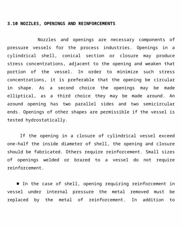
3.10 NOZZLES, OPENINGS AND REINFORCEMENTS
Nozzles and openings are necessary components of pressure vessels for the
process industries. Openings in a cylindrical shell, conical section or closure may produce
stress concentrations, adjacent to the opening and weaken that portion of the vessel. In order to
minimize such stress concentrations, it is preferable that the opening be circular in shape. As a
second choice the openings may be made elliptical, as a third choice they may be made around.
An around opening has two parallel sides and two semicircular ends. Openings of other shapes
are permissible if the vessel is tested hydrostatically.
If the opening in a closure of cylindrical vessel exceed one-half the inside diameter of
shell, the opening and closure should be fabricated. Others require reinforcement. Small sizes
of openings welded or brazed to a vessel do not require reinforcement.
■ In the case of shell, opening requiring reinforcement in vessel under internal pressure
the metal removed must be replaced by the metal of reinforcement. In addition to providing the
area of reinforcement, adequate welds must be provided to attach the metal of reinforcement
and the induced stresses must be evaluated.
Materials used for reinforcement shall have an allowable stress value equal to or greater
than of the material in this vessel wall except that, when such material is not available, lower
strength material may be used; provided, the reinforcement is increased in inversed proportion
to the ratio of the allowable stress values of the two materials to the ratio of the two materials

to compensate for the lower allowable stress value of any reinforcement having a higher
allowable stress value than that of the vessel wall.
3.11 SUPPORTS FOR VESSELS
Cylindrical and other types of vessels have to be supported by different methods. Vertical
vessels are supported by brackets, column, skirt, or stool supports, while saddles support
horizontal vessels. The choice of type of support depends on the height and diameter of the
vessel, available floor space, convenience of location, operating variables, the size of jjhe
vessel, the operating temperature and pressure and the materials of construction.
Brackets of lugs offer many advantages over other types of supports. They are
inexpensive, can absorb diametrical expansions by sliding over greased or bronze plates, jfcre
easily attached to the vessel by minimum amounts of welding, and easily leveled or shimmed
in the field. Lug supports are ideal for thick-walled vessels, but in thin-walled vessels, this type
of support is not convenient unless the proper reinforcements are used or many lugs are welded
to the vessel.
It is also necessary to ensure that, the attachment of the support to the vessel, which is
usually by fillet welds should be able to transfer the load safely from vessel to support and
that, the support should be strong enough to withstand the load of the vessel.
3.11.1 SKIRT

Vertical vessels are normally supported by means of suitable structure resting on a
reinforced concrete foundation. This support structure between the vessel and the j&undation
may consist of a cylindrical shell termed as skirt. The skirt is usually welded to the vessel
because the skirts are not required to withstand the pressure in the vessel; the selection of
material is not limited to codes. The skirt may be welded directly to the bottom dished head,
flush with the shell or to the outside of shell. There will be no stress from internal and external
pressure for the skirt, unlike for the shell, but the stresses from dead weight and from wind or
seismic bending moments will be maximum.


3.12ANCHOR BOLT
The bottom of skirt of vessel must be securely anchored to the concrete !foundations by
means of anchor bolts embedded in the concrete to prevent over turning from bending
moments induced by seismic and wind loads.
The concrete foundation is poured with adequate reinforcing steel to carry tensile loads.
The anchor bolts may be formed from steel rounds threaded at one end and usually with a
curved or hooked end embedded in the concrete will bond to the embedded surface of the
steel.
3.13METHODS OF FABRICATION
Process equipment is fabricated by a number of well-established methods such as
fcsion welding, casting, forging, machining, brazing and soldering and sheet metal forming.
Each method has certain advantages for particular types of equipment. However, fusion
welding is the most important method. The size, shape, service and material properties of the
equipment all may influence the selection of the fabrication method.
Gray iron casting have been widely used for the mass production of small pipe fittings
and are used to a considerable extent for large items such as cast iron pipe, heat exchanger
shells and evaporator bodies because of the superior corrosion resistance of cast iron as
compared with steel. Large diameter vessels cannot be easily cast, and the strength of gray
iron is not reliable for pressure vessels service. Cast steel may be used £>r small diameter
thick walled vessels. Further more, because of its higher strength and greater reliability as
compared with cast iron; it is more suitable for high-pressure service where metal porosity is
36

not a problem. The vessel diameter is still limiting because of a problem in casting. Alloy cast
steel vessels can be used for high-temperature and high-pressure installation.
: Forging is a method of shaping metal that is commonly used for certain vessel jparts
such as closures, flanges and fittings. Vessels with wall thickness greater than 10cm ire often
forged. Other special methods of shaping metal such as pressing, spinning and rolling of plates
are used for forming closures for vessel shells.
Riveting was widely used prior to the improvement of modern welding !fcchniques, for
many different kinds of vessels, such as storage tanks, boilers and a verity |tf pressure vessels.
It is still used for fabrication of non-ferrous vessels such as copper and aluminium. However,
welding techniques have become so advanced, that even these materials are often welded
today.
I. Machining is the only method other than cold forming that can be used to exact tecure
tolerances. Close tolerances are required for the mating parts of the equipment. Flange faces,
bushings, and bearing surfaces are usually machined in order to provide satisfactory
alignment. Laboratory and pilot plant equipment for very high-pressure service is sometimes
machined for solid stock, pierced ingots and forgings.
3.13.1 FUSION WELDING
It is the most widely used method of fabrication for the construction of steel vessels.
This method of construction is virtually unlimited with regard to size and is extensively used
for the fabrication and erection of large size product equipment in the field. There are two
types of fusion welding that are extensively used for fabrication of welds. These are,

1. The gas welding process in which a combustible, mixture of acetylene and
oxygen supply the necessary heat for fusion
2. The electric arc welding process, in which the heat of fusion is supplied by an
electric arc. Arc welding is preferred because of the reduction of heat in the
weld material, reduces the oxidation and better control of deposited weld metal.
3.14 PRESSURE TESTING OF CODE VESSELS
All pressure vessels designed to code specification except those exempted because of
small size must be tested hydrostatically, pneumatically or by means of ."PROOF TEST".
In the case of hydrostatic test, the vessel must be subjected to a hydrostatic test
pressure at least equal to one and a half times the maximum allowable pressure at the test
temperature. Following the application of the test pressure, all joints and connections snust be
inspected with the vessel under a pressure not less than 2/3'd of the test pressure. [Although
water is used in this test, any non-hazardous liquid may be used below its boiling temperature.
If the vessels are designed so that they camiot safely be filled with water (as in the case
of tall vertical towers design to handle vapours pneumatically), testing may be used. The
pneumatic test pressure should be at least 1.25 times the maximum allowable pressure at the
test temperature. In conducting pneumatic test, the pressure in the vessel should be gradually
increased to not more than half the test pressure. There after the test pressure should be raised
in increments of 1/10th of test pressure until the test pressure is reached. Following these, the
pressure should be reduced to maximum allowable pressure and held there for a sufficient
length of time to permit inspection of vessel.
The "proof test" can be used to establish the allowable working pressure in Vessels that
have parts, which the stress cannot be computed with satisfactory accuracy. In one procedure
38
of this test, all areas of probable high stress concentration are painted with a wash of lines or
another brittle coating. The pressure is raised and the vessel is inspected for signs of yielding
indicated by flaking or strain lines in the wash. The vessel is first observed.
Strain gauge measurements may be used in non destructive testing .In this case the
pressure is increased in increments of 1/10th the test pressure, each increment
I followed by relaxation of the pressure, until a permanent strain of 0.2% is reached. The
Vessel rating at the test temperature is equal to one-half the pressure producing this
jpennanent strain. A modification of the strain gauge measurement procedure is also kennitted
by the code. This method involves the use of measuring gauges at diametrically opposed
reference points in symmetrical structure.
In another version of the proof test, a sample used is tested to destruction and I
identical vessels are rated at the test temperature at l/5th the pressure at which the tested vessels
is failed.
CHAPTER.4 DESIGN PROCEDURE 4.1 DESIGN
OF SHELL AND ITS COMPONENTS
iijhe pressure vessel considered here is a single unit when fabricated. However, for the
Jonvenience of design, it is divided into the following parts. J (1) Shell; (2)head or cover; (3)
nozzles; (4) support;
Most of the components are fabricated from plates or sheets. Seamless or welded
pipes can also be used. Parts of vessels formed are connected by welded or riveted joints.

In designing these parts and connections between them, it is essential to take r into
account, the efficiency of joints. For welded joints, the efficiency may be taken
as 100% if the joint is fully checked by a radiograph and taken as 85%, eve if it is
checked at only a few points. If the radiographic test is not carried out 50 to 80%, I
efficiency is taken. Efficiencies vary between 70 to 85% in the case of riveted joints.
All these are made for pressure vessels operating at pressures less than 200kg/kmA2.
Design procedure is primarily based on fabrication by welding.
4.1.1 DESIGN OF CYLINDRICAL SHELLS UNDER PRESSURE
The equation for determining the thickness of cylindrical shells of vessels under
internal pressure are based upon a modified membrane-theory equation. The modification
empirically shifts the thin wall equation to approximate the "Lame" equation for thick-
walled vessel's shown above.
'4.2 WELDING STANDARDS
r
The success of fabrication by welding is dependent upon the control of the welding
variables such as experience and training of the welder, the use of proper materials, and
welding procedures. An inexperienced welder or welder using inferior materials, incorrect
procedures can fabricate a vessel that has a good appearance but has unsound joints, which
may fail in service. Thus, it is essential that the welding variables be controlled in order to
produce sound joints in the equipment. A number of codes and standards have been published
for the puipose.
The American welding society (AWS) established the basic standards for quantifying
operators and procedures. These standards of qualification form the basis of most of the
40

standards in various codes. For practical purposes, therefore the rules for qualifying welders
and welding procedures are essentially the same in the various codes and standards.
Each fabrication shop should establish welding procedures best suited to its need and its
equipment. To meet the welding standards previously mentioned, it is not necessary that,
regardless of the procedures used, the welded joints must pass the qualification tests for
welding procedures. To meet welding standards, welded joints must be tested to determine
tensile strength, ductility, and soundness. The required tests for the welding procedures
specified by API standard 12C involved the following. A. For Groove Welds:
1. reduced section -section-tension test ( for tensile strength )
2. Free bend test ( for ductility)
I 3. root bend test( For soundness )
4. face bend test( for soundness)
5. Side bend test ( for soundness)
i B. For fillet welds:
1. transverse -shear test( for shear strength)
I 2. free bend test( for ductility)
3. Fillet weld - soundness test
The minimum results required by the tests such as those listed above
are described in detail in the various codes. A few representative
requirements are:
a. The tensile strength in the reduced section tension test shall not be
less
than 95% of the minimum tensile strength of the material being welded

b. The minimum permissible elongation in the free bend test is 20%
c. The shearing strength of the welds in the transverse shear test shall
not
be less than 87% if the minimum tensile strength of the material being
welded.
d. In the various soundness tests, the convex surface of the specimen is
examined for the appearance of cracks or other defects. If any cracks
exceeds
0.3cm, in any direction, the joint is considered to have failed.
42

H2.1 TYPES OF WELDED JOINTS
A variety of welded joints are used in the fabrication of vessels. The selection of the
type of joint depends upon the service, the thickness of the metal fabrication procedure and
code requirements. The following figure is a diagram from the API-ASME code for unified
pressure vessels which illustrates some of the types of welded joints used in the welding of
steel plates for the fabrication of pressure vessels.
4.2.2 WELDED JOINTS EFFICIENCIES
The use of welded joints may result in reduction in the strength of the part at or near
the world. This may be result of metallurgical discontinuities and residual stress. The code
rules make allowance for these factors by specifying joint efficiencies for various types of
welds with and with out stress relief and radiographing. The designs are permitted some option
in the selection of the kind of weld joint to be and in whether or not, the welded joints must be
radio graphed.
All vessel shells having a thickness greater than 1 1/4 inch or greater than ld+50)120
{where, d=inside diameter or 20 inches which ever is greater: must be thennally stress
received.
fVessels of any thickness can be fabricated from the following steels must be stress
relieved, SA-301.Grade B; SA-302; SA-270, Grades WC-5; SA-357; SA-387;Grades B,C,D
and E and chrome-molybdenum steel having a chrome content greater than 0.7%. In addition,
vessels having a shell thickness greater than 1.4 cm must be thermally stress relieved if they
are fabricated of the following steels: SA-202; SA-203; SA-204; SA-225; SA-299; SA-301,
Grade A, and any steel having specified molybdenum content of 0.4 to 0, 65% and a chrome
content not greater thanvO.7%. In addition, steel greater than 2.5 cm in thickness must be
stress relieved if they meet the Verification of the following: SA-212; SA-105, Grade II: SA-
181, Grade II; SA-266, Grade II SA-94; & SA-216, Grade WCB.
43

If high alloy steels are used, stress relieving is not required in the case of austenitic
chromium nickel steels. The increase in joint efficiency may be used if these steels are heat
treated at over 480 x C. if the vessel are constructed of ferrites chromium stainless steels,
stress relieving is required in al vessel thickness except in the case of type 415 welded with
electrodes, a process producing austenitic weld. The code gives the temperature and describes
the procedures to be used in thermal stress relieving.
Radiography examination is required for double welded butt joints. If the plastic
thickness is greater than 2.5 cm complete radio graphing of each welded joints is required, if
the vessel is fabricated of SA-202; SA-203; SA-204; SA-225; SA-299; SA-301 or SA-302.
Vessels of thickness that are fabricated if SA-353, SA-357 or SA-387. must be radio graphed.
Also vessels constructed of high alloy steels such as type 405 jwelded with straight chromium
electrodes and type -410 &430 welded with any electrodes must be radio graphed in all
thickness except when carbon content does not exceed 0,08%, the plate thickness does not
exceeded 3.8 cm and austenitic welds are used.
k.23 JOINT EFFICIENCIES AND CORROSION ALLOWANCES
In vessels for atmospheric storage, the welded joints are seldom stress relieved or radio
graphed. The welded seams may not be as strong as the adjacent rolled steel plate ■ the shell.
It has been found from experience that, an allowance may be made for such Weakness by
introducing a "joint efficiency factor E" in the equations. This factor is llways less than unity
and is specified for a given type of welded construction in the prarious codes.
The thickness of the metal, C allowed for any anticipated corrosion is then added to the
calculated required thickness, and the final thickness value rounded off to the nearest nominal
plate size of equal or greater thickness.
4.3 DESIGN TEMPERATURE
The temperature used in design shall not be less than the mean metal temperature
except operating conditions for parts considered. If necessary, the metal temperature shall be
determined by computation using accepted heat transfer procedures or by measurement from
1 44

equipment in service, under equivalent operating conditions. In no case, shall the temperature
of surface of metal exceed the maximum temperature listed in the stress tables for materials
not exceed the maximum temperature limitation specified elsewhere in ASME section VIII.
div 1.
4.4 NOZZLE NECK THICKNESS
Except for opening for inspection only, the wall thickness of a nozzle neck or other
connection shall not be less than the greater of the following.
1. The thickness computed for the applicable loadings in UG -22 plus the thickness added
for corrosion allowance in the connections.
1. Smaller of the following.
For vessels under internal pressure only, the thickness required for pressure for the
shell at the location. Where the nozzle neck attached to the vessel, but on no case less
than the minimum thickness specified for the material in UG - 16.
4.5 DESIGN OF NOZZLE REINFORCEMENT
As per UG -37 of ASME sec. VIII, div 1.
Reinforcement is provided in amount and distribution such that the area requirements
for reinforcement are satisfied for all planes through the centre of opening and normal to
vessel surface. For a circular opening in a cylindrical shell, the plane containing the axis of
shell is the plane of greatest loading due to pressure. Not less than half the required
reinforcement shall be on each side of the centre line of single openings. Reinforcement is
provided for openings having diameter greater than 50mm.
4.6 DESIGN OF SKIRT SUPPORT
45
Skirt is the most frequently used and the most satisfactory support for vertical :
vessels. It is attached by continuous welding to the head and usually the required size of | this
welding determines the thickness of the skirt.
In calculation of the required weld size, the value of the joint efficiency is given by the
code UW -12 may be used.
DESIGN DATA
[Code ASME SECTION VIII DIVISION 1, 2004Fluid handled DEASpecific gravity of fuel 1.051Operating pressure 30 Kg/cm2
Operating temperature 40°CDesign pressure 35 Kg/cm2
Design temperature 70°CJoint efficiency 1Corrosion allowance 3 mmHydraulic test pressure 45.5 Kg/cm2
Pneumatic test pressure N/A
1 46

I.JHUHJ----------U90KD
Pig: model of amine absorber pressure vessel
47

48
CHAPTER.5
DESIGN CALCULATIONS
5.1 DESIGN OF HEAD
5.1.1 TOP HEAD

Equipment
Code
Material
Max Allowable Stress, S
Design Pressure, P
Design Temperature, T
Top Head
ASME Section VIII Div 1
SA516 Gr60 118 MPa
3.434 MPa 343 K
49

| A 2:1 ellipsoidal top head is selected. According to
UG 31 of ASME Section VIII Div 1, Minimum
thickness required, tr = P.D +C,
2SE - 0.2 P
where D =intemal diameter
E= joint efficiency=1.0
C= corrosion allowance= 3mm
50

tr:
3.434 x 1000
2xH8xl-0.2x 3.434
51

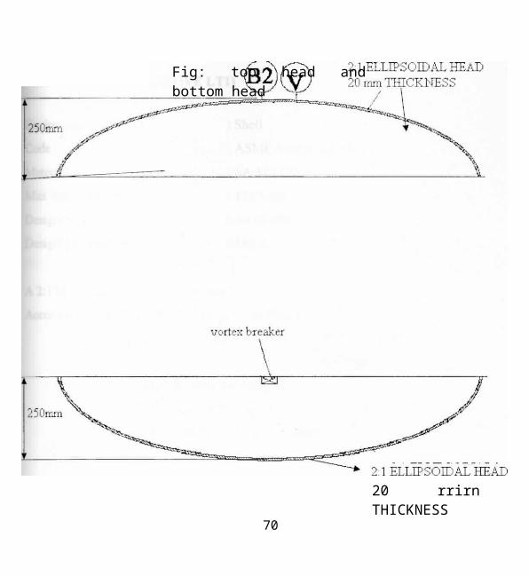
Nominal thickness, t = 20mm
Height of ellipsoidal head, h = D/4= 250mm
t,= 17.59mm
52

Ll.2 BOTTOM HEAD
fcquipment
Code
Material
Max Allowable Stress, S
besign Pressure, P Design
Temperature, T
Bottom Head
ASME Section VIII Div 1
SA516Gr 60
118MPa
3.455 MPa
343 K
53

A 2:1 ellipsoidal bottom head is selected. According
to UG 31 of ASME Section VIII Div 1, Minimum
thickness required, tr = P.D
54

2SE-0.2P

E= joint efficiency=1.0 C=
corrosion allowance= 3mm tr =
3.455x1000 2xH8xl-
0.2x3.455
56

t = 17.68mm
Nominal thickness, t = 20mm
Height of ellipsoidal head, h = D/4= 250mm
57

20 rrirn THICKNESS
Fig: top head and bottom head
58

5.2 DESIGN OF SHELL
5.2.1 TOP SECTION (ABOVE LT1)
59

Equipment
Code
Material
Max Allowable Stress, S
Design Pressure, P
Design Temperature, T
Shell
ASME Section VIII Div
SA516Gr 60 118 MPa
3.434 MPa 343 K
60

A 2:1 ellipsoidal top head is selected. According to
UG 27 of ASME Section VIII Div 1, Minimum
thickness required, tr = P.R
61

SE-0.6P-
where R =internal radius E= joint
efficiency= 1.0 C= corrosion
allowance= 3mm

tr3.434x500
118x1-0.6x3.434
+ 3
63

t,= 17.81mm
64

Nominal thickness, t 20mm
65

5.2.2 BOTTOM SECTION (BELOW LT1)
66

Equipment Code Material
Max Allowable Stress, S
Design Pressure, P
Design Temperature, T
Shell
ASME Section VIII Div 1
SA516 Gr60 118 MPa
3.452 MPa 343 K
67

[A 2:1 ellipsoidal top head is selected. : According to
UG 27 of ASME Section VIII Div 1, Minimum
thickness required, tr = P.R +
SE-0.6P
where R =internal radius
E= joint efficiency=1.0
C= corrosion allowance= 3mm
3.432x500 .118xl-.6x3.432
t, = 17.89mm
Nominal thickness, t = 20mm
68

L T I
.20 mm thick
L T 2
70
1000 i

Figure: top shell section and bottom head section
71

5.3 DESIGN OF NOZZLES
Nozzle Mark
Equipment
SizeNB
Code
Material
Max Allowable Stress, S
Design Pressure, P Design
Temperature, T
: V
: Vent with valve : 50 mm
: ASME Section VIII
Div : SA 106 GrB : 118
MPa : 3.434 MPa : 343 K
From ANSI 3.36.10,
Outside diameter D0 = 60.3 mm Ro = 30.15
mm
72

A' P.Ro
SE + 0.4P
+ C
73

3.434x30.15
118x1+0.4x35
+ 3
74

3.87 mm
B' = head thickness + C
- 2 0 + 3
= 23 mm
75

From pipe tables, Standard wall thickness = 3.91 mm C =
(std. wall thickness x .875) + C
= (3.91 x .875)+ 3
= 6.421 mm D' = lesser of (B' and C) =
6.421 mm E' = greater of (A' and D') = 6.421
mm
76

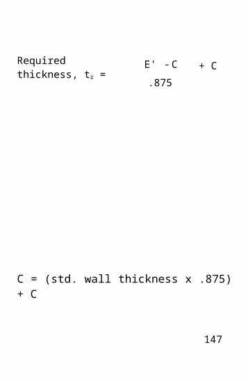
Required thickness, tr = E ' - C
.875
+ C
From pipe tables, Standard wall thickness = 11.91 mm
77

6.421-3
.875 -
+ 3
78

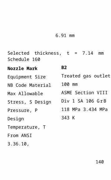
6.91 mm
Selected thickness, t = 7.14 mm Schedule 160
From pipe tables, Standard wall thickness = 11.91 mm
79

Nozzle Mark
Equipment Size NB
(Code Material
Max Allowable Stress, S
Design Pressure, P
Design Temperature, T
Ml
Manhole
600 mm
ASME Section VIII D
SA 106 G r B 118 MPa
3.452 MPa 343 K
80

From ANSI 3.36.10,
Outside diameter, D0 = 609.6 mm
Ro = 304.8 mm
From pipe tables, Standard wall thickness = 11.91 mm
81

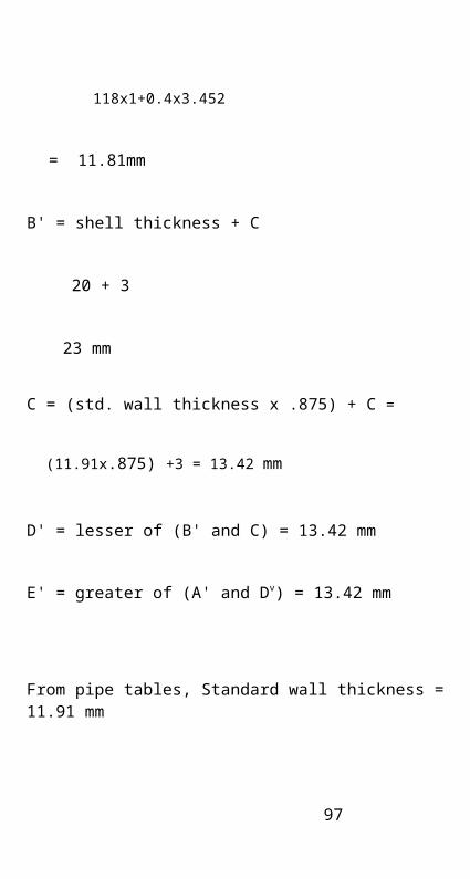
A' P.Ro + C ■= 11.81 mm
82

L§E + 0.4P
From pipe tables, Standard wall thickness = 11.91 mm
83

3.452x304.8 +3
84

118x1+0.4x3.452
= 11.81mm
B' = shell thickness + C
20 + 3
23 mm
C = (std. wall thickness x .875) + C = (11.91x.875) +3 = 13.42
mm
D' = lesser of (B' and C) = 13.42 mm
E' = greater of (A' and Dv) = 13.42 mm
From pipe tables, Standard wall thickness = 11.91 mm
85

Required thickness, t, = E' - C
.875
+ C
86

13.42-3
.875
+3
From pipe tables, Standard wall thickness = 11.91 mm
87

14.91 mm
Selected thickness, t = 15.88 mm
88

Nozzle Mark Equipment
Size NB Code Material
Max Allowable Stress, S
Design Pressure, P
Design Temperature, T
M2
Manhole
600 mm
ASME Section VIII Div 1
SA 106 G r B 118 MPa
3.434 MPa 343 K
From pipe tables, Standard wall thickness = 11.91 mm
89

From ANSI 3.36.10,
Outside diameter, D0 = 609.6 mm
Ro = 304.8 mm
90

A' P.Ro .
SE + 0.4P-
+ C
From pipe tables, Standard wall thickness = 11.91 mm
91

3.434x304.8
118x1+0.4x3.434
+ 3
92

11.76 mm
B' = shell thickness + C
20 + 3
23 mm
C = (std. wall thickness x .875) + C - = (ll.91x.875) +3 I; F 13.42
mm
D' = lesser of (B' and C) = 13.42 mm E' = greater of (A' and D') =
13.42 mm
From pipe tables, Standard wall thickness = 11.91 mm
93

iRequired thickness, tr = E ' - C
.875
+ C
94

13.42-3
.875
+3
From pipe tables, Standard wall thickness = 11.91 mm
95
= 14.91 mm
Selected thickness, t = 15.88 mm
96
[Nozzle Mark
Equipment Size NB
[Code
! Material
Max Allowable Stress, S
Design Pressure, P Design
Temperature, T From ANSI
3.36.10,
Outside diameter, D0 = 60.3mm Ro
= 30.15mm
From pipe tables, Standard wall thickness = 3.91 mm
97
: LT1
Level Transmitter 50 mm
ASME Section VIII Div 1
SA 106 G r B 118 MPa
3.434 MPa 343 K

A' P.Ro + C
98

SE + 0.4P-
From pipe tables, Standard wall thickness = 3.91 mm
99

3.434 x 30.15
118x1+0.4x3.434
+ 3
100

- 3.87 mm
B' = shell thickness + C
= 20 + 3
= 23 mm
From pipe tables, Standard wall thickness = 3.91 mm
101

102
fc' = (std. wall thickness x .875) + C
(3.91x.875) + 3
6.421 mm
W = lesser of (B' and C) = 6.421 mm
p' = greater of (A' and D') = 6.421 mm

Required thickness, t, E' - C
.875
+ C
From pipe tables, Standard wall thickness = 3.91 mm
103

6.421 -3
.875 .
+ 3
104

6.91 mm
Selected thickness, t = 7.14 mm Schedule 160
From pipe tables, Standard wall thickness = 3.91 mm
105

[Nozzle Mark
Equipment
Size NB
Code
Material
Max Allowable Stress, S
Design Pressure, P
Design Temperature, T I From ANSI 3.36.10,
LT2
Level Transmitter 50 mm
ASME Section VIII Div
SA 106 G r B 118 MPa
3.452 MPa 343 K
106

Outside diameter, D0 = 60.3 mm
R0 = 30.15 mm
From pipe tables, Standard wall thickness = 3.91 mm
107

A' P.Ro - C
108

SE + 0.4P
From pipe tables, Standard wall thickness = 3.91 mm
109
3.452 x 30.15
18x1+0.4x3.452
+ 3
110

3.87 mm
B' = shell thickness + C
= 20 + 3
23 mm
C = (std. wall thickness x .875) + C . =(3.91x.875) + 3
= 6.421 m m . M = lesser of (B' and C) = 6.421 mm
I' = greater of (A' and D') = 6.421 mm
From pipe tables, Standard wall thickness = 3.91 mm
111

Required thickness, t, = E' - C
.875
+ C
112

6.421-3
.875 .
+ 3
From pipe tables, Standard wall thickness = 3.91 mm
113

= 6.91 mm
Selected thickness, t = 7.14 mm Schedule 160
Nozzle Mark
Equipment Size NB
Code Material
Max Allowable
Stress, S Design
Pressure, P Design
Temperature, T
From ANSI
3.36.10,
Outside diameter, D0 = 60.3
mm R0 =
30.15
mm
114
SP1
Standpipe
50 mm
ASME Section VIII Div 1
SA 106 G r B .118 MPa
3.452 MPa 343 K

A' P.Ro + C
C = (std. wall thickness x .875) + C
115

SE + 0.4P
116

3.452 x 30.15
118x1+0.4x3.452
+ 3
C = (std. wall thickness x .875) + C
117

3.87 mm
B' = shell thickness + C
= 20 + 3
= 23 mm
From pipe tables, Standard wall thickness = 3.91 mm
= (3.91*.875) + 3 f =6.421
mm
D' = lesser of (B' and C) = 6.421 mm I E' =
greater of (A' and D') = 6.421 mm
118

[Required thickness, tr = E ' - C
.875
+ C
C = (std. wall thickness x .875) + C
119

6.421-3
.875 .
+ 3
120

6.91 mm
Selected thickness, t = 7.14 mm Schedule 160
Nozzle Mark
Equipment Size NB
Code . Material
Max Allowable Stress,
S Design Pressure, P
Design Temperature, T
iFrom ANSI 3.36.10,
Outside diameter, D0 = 60.3
mm
C = (std. wall thickness x .875) + C
121
SP2
Standpipe
50 mm
ASME Section VIII Div 1
SA 106 G r B 118 MPa
3.434 MPa 343 K

R0 = 30.15 mm
122

A ' = P-Rn
LSE + 0.4P.
+ C
C = (std. wall thickness x .875) + C
123

' 3.434 x 30.15
118x1+0.4x3.452
+ 3
124

= 3.87 mm
B' = shell thickness + C
20 + 3
23 mm
From pipe tables, Standard wall thickness = 3.91 mm
= (3.91x.875) + 3 = 6.421 mm D' = lesser of (B' and C) =
6.421 mm I
E' = greater of (A' and D') = 6.421 mm
C = (std. wall thickness x .875) + C
125

Required thickness, tr = E ' - C
.875
+ C

6 . 4 2 1 -
3 .875
+ 3
C = (std. wall thickness x .875) + C
127

6.91 mm
Selected thickness, t = 7.14 mm Schedule 160
Nozzle Mark
Equipment Size NB
Code Material
Max Allowable Stress,
S Design Pressure, P
Design Temperature, T
From ANSI 3.36.10,
Outside
diameter, D0 = 114.3 mm R0 =
57.15 mm
128
B2
Treated gas outlet 100 mm
ASME Section VIII Div 1
SA 106 G r B 118 MPa
3.434 MPa 343 K

A' P.R0 + C =4.64 mm
C = (std. wall thickness x .875) + C
129

SE + 0.4P
130

3.434x57.15 + 3
C = (std. wall thickness x .875) + C
131

118x1+0.4x3.434
4.64 mm
B' = head thickness + C
= 20 + 3
= 23 mm
From pipe tables, Standard wall thickness = 4.78 mm
= (4.78*.875) + 3 5
= 7 . 1 8 mm
D' = lesser of (B' and C ) = 7.18 mm 1 E' =
greater of (A' and D') = 7.18 mm ■
132

Required thickness, tr = E' - C
.875
+ C
C = (std. wall thickness x .875) + C
133

7.18-
3 .875
- 3
134

7.78 mm
Selected thickness, t = 7.92 mm Schedule 40
Nozzle Mark Equipment
Size NB Code Material
Max Allowable Stress,
S Design Pressure, P
Design Temperature, T
From ANSI 3.36.10,
Outside
diameter, D0
= 114.3 mm Ro = 57.15 mm
C = (std. wall thickness x .875) + C
135
Al
Recycle gas inlet 100
mm
ASME Section VIII D
SA 106 G r B 118 MPa
3.434 MPa 343 K

A' = P-RQ
SE + 0.4P-
+ C
136

3.434x57.15 U
18x1+0.4x3.434-
+ 3
C = (std. wall thickness x .875) + C
137

= 4.64 mm
B' = head thickness + C
20 + 3
= 23 mm
From pipe tables, Standard wall thickness = 4.78 mm
(4.78x.875) + 3
7.18 mm
D' = lesser of (B' and C ) = 7.18 mm E' = greater of (A' and
D') = 7.18 mm *
138

[Required thickness, tr = E ' - C
.875
+ C
C = (std. wall thickness x .875) + C
139
7.18-
3 .875
+ 3
140

= 7.78 m m
Selected thickness, t = 7.92 mm Schedule 40
Nozzle Mark Equipment
Size NB Code Material
j Max Allowable Stress, S
Design Pressure, P
Design
Temperature, T
C = (std. wall thickness x .875) + C
141
Bl
RDEA outlet 80 mm
ASME Section VIII Di
SA 106 G r B 118 MPa
3.455 MPa 343 K

[From ANSI
3.36.10,
Outside diameter, D0 = 88.9
mm R0 =
44.45
m m
142

: A ' = P-PvQ
SE + 0.4P
+ C
143

3,455x44.45
118x1+0.4x3.455
+ 3
144

4.29 mm
,B' = head thickness + C =
20 + 3 = 23 mm
From pipe tables, Standard wall thickness = 4.37 mm C =
(std. wall thickness x .875) + C
= (4.37*.875) + 3
= 6.82 mm
D' = lesser of (B' and C ) = 6.82 mm
E' = greater of (A' and D ' ) = 6.82 mm
145

Required thickness, tr F - C
.875
+ C
146
6 . 8 2 - 3
- .875
+ 3
C = (std. wall thickness x .875) + C
147

7.37 mm
Selected thickness, t = 7.62 mm Schedule 80
Nozzle Mark
Equipment Size NB
Code Material
Max Allowable
Stress, S Design
Pressure, P Design
Temperature, T
From ANSI
3.36.10,
148
A2
LDEA outlet 80 mm
ASME Section VIII Div
SA 106 G r B 118 MPa
3.434 MPa 343 K

Outside diameter, D0 = 88.9
mm
R0 = 44.45 mm
C = (std. wall thickness x .875) + C
149

A' P-RQ SE
+ 0.4P.
+ C
150

3.434x44.45 ll
18x1+0.4x3.434-
+ 3
C = (std. wall thickness x .875) + C
151

= 4.28 mm
B' = head thickness + C
20 + 3
23 mm
From pipe tables, Standard wall thickness = 4.37 mm
(4.37x.875) +3
6.82 mm
D' = lesser of (B' and C) = 6.82 mm E' =
greater of (A' and D') = 6.82 mm
152

Required thickness, tr = E' - C
.875
+ C
C = (std. wall thickness x .875) + C
153

6 . 8 2 - 3
.875
+ 3
154

7.37 mm
Selected thickness, t — 7.62 mm Schedule 80
C = (std. wall thickness x .875) + C
155


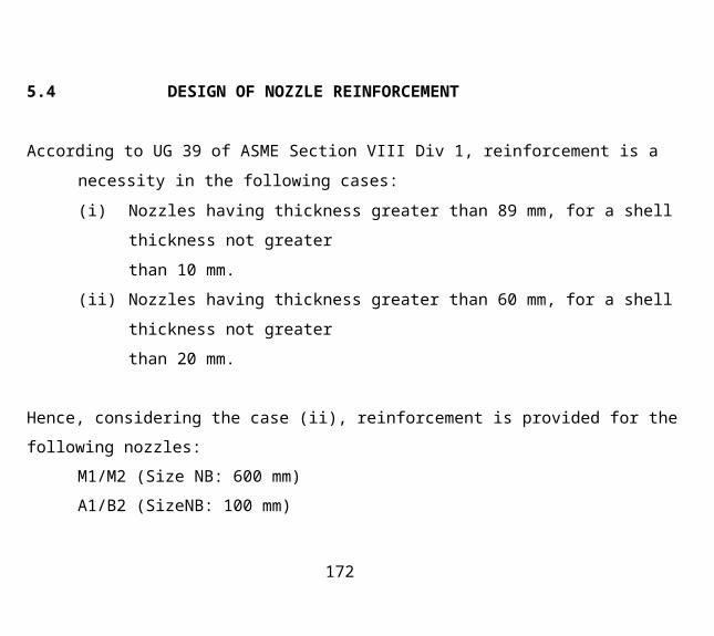
5.4 DESIGN OF NOZZLE REINFORCEMENT
According to UG 39 of ASME Section VIII Div 1, reinforcement is a necessity in the following
cases:
(i) Nozzles having thickness greater than 89 mm, for a shell thickness not greater
than 10 mm.
(ii) Nozzles having thickness greater than 60 mm, for a shell thickness not greater
than 20 mm.
Hence, considering the case (ii), reinforcement is provided for the following nozzles:
M1/M2 (Size NB: 600 mm)
A1/B2 (SizeNB: 100 mm)
B1/A2 (Size NB: 80 mm)
Limits of reinforcement:
(i) Parallel to vessel walls:
157

Greater of [(nozzle inside diameter) & (nozzle inside radius+ shell
thickness + nozzle thickness)]
(ii) Normal to vessel walls:
Lesser of [(2.5 times shell thickness) & {(2.5 times nozzle thickness)
+ (reinforcement plate thickness)}]
158
Nozzle Mark
Size NB
Code
Materials
Max. Allowable Stresses
Design Pressure
Ml
600 mm
ASME Section VIII Div
Shell
Nozzle
Reinforcement 118 MPa
3.452 MPa
S A 5 1 6 G r
60 SA 106
G r B S A 5 1 6
Gr 60
159

Outside diameter of nozzle, do
Inside diameter of nozzle, di
Inside radius of nozzle, ri Required
thickness of seamless nozzle, trn Nominal
thickness of nozzle, tn Required thickness
of shell, tr Nominal thickness of vessel wall,
t Thickness of reinforcement plate, tp Inside
radius of vessel, Ri
= 609.6 mm
= (do - 2 x nozzle thickness)
= (609.6-2x15.88)
= 577.84 mm
= 288.92 mm
= 14.91 mm
= 15.88 mm
= 17.89 mm
= 20 mm
= 20 mm (assumed) = 301.5
mm
160

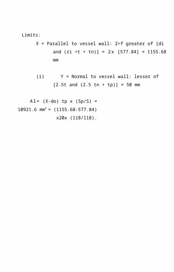
Limits:
X = Parallel to vessel wall: 2>f greater of [di and (ri +t + tn)] = 2 x
[577.84] = 1155.68 mm
(i) Y = Normal to vessel wall: lesser of [2.5t and (2.5 tn + tp)] = 50
mm
A l = (X-do) tp x (Sp/S) = 10921.6 mm2 =
(1155.68-577.84) x20x (118/118).

= 11565.6 mm2 Area of shell
available, AT = (t-tr) di
= (20-17.89) x 577.84 =
1219.24 m m 2
A2" = 2(t- tr) x (t+tn) =151.41 mm2 = 2*
(20-17.89)x(20+15.88) = 151.41 mm2
A2= greater of (A2' and A2") = 1219.24 mm2
Area of nozzle available, A3 = 2(tn-trn) Y (Sn/S)
= 2x(15.88-14.91)x50x( l 18/118) = 97
mm2
Total available area, AA= A l +A2+A3= 12237.84 mm2
= 11565.6+1219.24+97 =
12881.84 mm2
Required areas for reinforcement:
A'= di x tr
= 577.84 x 17.89
= 10337.56 mm2
A"=2xtrx(ro-ri)(l-Sn/S)
= 2xl7.89x(304.8-288.92)x( l - ( l 18/118) = 0
mm2

RA = A'+A" = 10337.56 mm2 Available area (AA) is greater than the required area (RA);
hence selected thickness, tp=20 mm is secure.

Nozzle Mark
Size NB
Code
Materials
Max. allowable Stresses
Design Pressure
M2
600 mm
ASME Section VIII Div 1
Shell
Nozzle
Reinforcement : 118 MPa :
3.434 MPa
S A 5 1 6 G r
60 SA 106 Gr
B S A 5 1 6 Gr
60

Outside diameter of nozzle, do
Inside diameter of nozzle, di
Inside radius of nozzle, ri Required
thickness of seamless nozzle, trn Nominal
thickness of nozzle, tn Required thickness of
shell, tr Nominal thickness of vessel wall, t
Thickness of reinforcement plate, tp Inside
radius of vessel, Ri
= 609.6 mm = (do - 2
x nozzle thickness) = (609.6-
2x15.88) = 577.84 mm =
288.92 mm = 14.91 mm =
15.88 mm = 17.81 mm = 20
mm
= 20 mm (assumed) = 301.5
mm

Limits:
X = parallel to vessel wall: 2 =
2 x [577.84] =
1155.68 mm
(ii) Y = Normal to vessel wall: lesser of [2.5t and (2.5 tn + tp)] = 50
mm
A l = (X-do)tp x (Sp/S) = 10921.6 mm2
= (1155.68-577.84)x20x(l 18/118)
- 11565.6 mm2
Area of shell available, A2' = (t-tr) x di
= (20-17.81) x 577.84 = 1265.47 mm2
A2" = 2(t- tr) x (t+tn)
= 2 x (20-17.81) x (20+15.88) = 157.15 mm2
A2= greater of (A2' and A2") = 1265.47 mm2
Area of nozzle available, A3 = 2 x (tn-trn) xYx (Sn/S)
= 2 x (15.88-14.91) x50x (118/11 = 97 mm2
Total available area, AA= A1+A2+A3
greater of [di and (ri +t +

= 11565.6+1265.47+97 = 12928.07
mm2
Required areas for reinforcement: A'= di x tr
= 577.84x17.81
= 10291.33 mm2
A"=2xtrx(ro-ri)(l-Sn/S)
= 2 x 17.81 x(304.8-288.92)x(l-( 118/118)) = 0 mm2


RA = A'+A"
= 10291.33 mm2
Available area (AA) is greater than the required area
(RA); hence selected thickness, tp=20 mm is secure.
Nozzle Mark
Size NB
Code
Materials
Max. allowable Stresses
Design Pressure
A1/B2
100 mm
ASME Section VIII Div 1
Shell
Nozzle
Reinforcement 118 MPa
3.452 MPa
S A 5 1 6 G r
60 SA 106
G r B
S A 5 1 6 G r
60
169

Outside diameter of nozzle, do
Inside diameter of nozzle, di
Inside radius of nozzle, ri Required
thickness of seamless nozzle, tm Nominal
thickness of nozzle, tn Required thickness of
shell, tr Nominal thickness of vessel wall, t
Thickness of reinforcement plate, tp Inside
radius of vessel, Ri
114.3 mm
(do - 2 x nozzle thickness)
(114.3-2x7.92)
98.46 mm
49.23 mm
7.78 mm
7.92 mm
17.81 mm
20 mm
20 mm (assumed) 301.5 mm
170

Limits:
X = parallel to vessel wall: 2
= 2x98.46 = 196.92
mm
greater of [di and (ri +t + tn)]
172

RA = A'+A"
= 10291.33 mm2
Available area (AA) is greater than the required area
(RA); hence selected thickness, tp=20 mm is secure.
Y = Normal to vessel wall: lesser of [2.5t and (2.5 tn + tp)] = 39.8
mm
A l = ( X - d o ) t p x ( S p / S )
= (196.92-114.3) x20x (118/118)'
= 1652.4 mm2
Area of shell available, A2' = (t-tr) di
= (20-17.81) x 98.46 = 215.63 mm2
A2" =2(t- tr) x (t+tn)
= 2x (20-17.81)x(20+7.92) = 122.29 mm2
A2= greater of (A2' and A2") = 215.63 mm2
Area of nozzle available, A3 = 2(tn-trn) Y (Sn/S)
= 2x (7.92-7.78)x39.8x( l 18/118) =11.14 mm2
Total available area, AA= A1+A2+A3
= 1652.4+215.63+ 11.14 = 1879.17 nun2
173

Required areas for reinforcement: A'= di x tr =
98.46x17.81 = 1753.57 mm2
A"= 2(trxro-ri) (1-Sn/S)
= 2xl7.81x (57.15-49.23) x (1-(118/118)) = 0 mm2
174

RA = A'+A"
= 1753.57 mm2
Available area (AA) is greater than the required area
(RA); hence selected thickness,. tp=20 mm is secure.
Nozzle Mark
Size NB
Code
Materials
Max. allowable Stresses
Design Pressure
A2/B1
80 mm
ASME Section VIII Div 1
Shell Nozzle
Reinforcement : 118 MPa :
3.452 MPa
S A 5 1 6 G r 6
0 SA 106 Gr
B S A 5 1 6 G r
60
176

Outside diameter of nozzle, do
Inside diameter of nozzle, di
Inside radius of nozzle, ri Required
thickness of seamless nozzle, trn Nominal
thickness of nozzle, tn Required thickness
of shell, tr Nominal thickness of vessel wall,
t Thickness of reinforcement plate, tp Inside
radius of vessel, Ri
88.9 mm
(do - 2 x nozzle thickness)
88.9-(2x7.62)
73.66 mm
36.83 mm
7.37 mm
7.62 mm
17.89 mm
20 mm
20 mm (assumed) 301.5
mm
177

Limits: _
X = Parallel to vessel wall: 2 x greater of [di and (ri +t +tn)] =
2x73.66 = 147.32 mm
Y = Normal to vessel wall: lesser of [2.5t and (2.5 tn + tp)] = 39.05
mm
A l = ( X - d o ) t p x ( S p / S )
= (147.32-88.9) x20x (118/118)
= 1168.4 mm2
Area of shell available, A2' = (t-tr) di
= (20-17.89) X73.66
155.43 mm2
A2" =2(t- tr) x (t+tn)
= 2x (20-17.89) x (20+7.62) = 116.56 mm2
A2= greater of (A2' and A2")
155.43 mm2
Area of nozzle available, A3 = 2(tn-trn) Y (Sn/S)
= 2 x (7.62-7.37) x39.05x (118/118)
19.53 mm2
Total available area, AA= A1+A2+A3
\ = 1168.4+155.43+19.53

= 1324.36 mm2
Required areas for reinforcement: A'= di x tr
= 73.66x17.89
= 1317.78 mm2
A"= 2(trxro-ri)(l-Sn/S)
= 2xl7.89x(44.45-36.83)x( l -(118/118) = 0 mm2

RA = A'+A"
= 1317.78 mm2

181


fig limits of nozzle reinforcement
183

5.5 ESTIMATION OF LOADS
ERECTION
Shell
Top Head7i/4[(Do2-Di2) x h x p] = 5030.946 kg 1/3 x
4/3 x 7i [(Ro3-Ri3) x h] = 44.478 kg

Bottom Head
Ladder
Demister
1/3 x 4/3 x 7i [(Ro -Rf) x h] = 44.478 kg
1250 kg (assumed) 35 kg (assumed)

Nozzles:
i) Nozzle Mark: V
Pipe mass: 7i/4[(do2-di2) x h x p] = 2.012 kg Type
of flange: 300# Mass of flange: 4.1 kg Total
mass = 6.112 kg
ii) Nozzle Mark: M1/M2
Pipe mass: 7c/4[(do2-di2) x h x p ] = 192.95 kg
Type of flange: 300#
Mass of flange: 247 kg
Total mass = 439.95 kg x 2 = 879.91 kg
iii) Nozzle Mark: LT1/LT2
Pipe mass: 7t/4[(do2-di2) x h x p] = 6.741 kg
Type of flange: 300#
Mass of flange: 4.49 kg
Total mass = 11.23 kg x 2 = 22.46 kg

iv) Nozzle Mark: SP1/SP2
Pipe mass: 7i/4[(do2-di2) x h x p] = 6.741 kg
Type of flange: 300#
Mass of flange: 4.49 kg
Total mass = 11.23 kg x 2 = 22.46 kg
v) Nozzle Mark: A1/B2
Pipe mass: 7i/4[(do2-di2) x h x p] = 4.215 kg
Type of flange: 300#
Mass of flange: 11.82 kg
Total mass = 16.04 kg x 2 = 32.08 kg
vi) Nozzle Mark: A2/B1
Pipe mass: T:/4[(do2-di2) x h x p] = 3.293 kg
Type of flange: 300#
Mass of flange: 7.12 kg
Total mass = 10.413 kg x 2 = 20.83 kg

Total mass of nozzles : 983.843 kg
Trays : 10 x 0.8 x n/4 x Di2 x h x p = 246.614kg

Total Weight 7635.36 kg
189

HYDRO TEST

Mass of water
Total mass
: (Volume of water) x p = 7866.164 kg :
15523.524 kg
191
OPERATION

Mass of water column
Mass of liquid hold up on trays
Total mass
: (Volume of water up to LT1) x p =
1610.06 kg
: 10 x 0.8 x TI/4 x Di2 x h x p = 125.66 k t
: 7635.36 kg + 1610.06 kg + 125.66 kg =
9371.082 kg
193

SHUT DOWN
7c/4[(Do2-(Di+2C)2) x h x p] = 4288.88 kg 1/3 x 4/3 x 7i [(Ro3-
(Ri+2C)3) x h] = 38.238 kg 1/3 x 4/3 x 7i [(Ro3-(Ri+2C)3) x h] =
38.238 kg
Nozzles:
i) Nozzle Mark: V
Pipe mass: 7t/4[(do2-(di+2C)2) x h x p] = 1.632 kg Type
of flange: 300# Mass of flange: 4.1 kg Total mass =
5.73 kg
ii) Nozzle Mark: M1/M2
Pipe mass: 7t/4[(do2-(di+2C)2) x h x p] = 78.162 kg
Type of flange: 300# Mass of flange: 247 kg
anen
Top Head
Bottom
Head

Total mass = 325.162 kg x 2 = 650.32 kg
iii) Nozzle Mark: LT1/LT2
Pipe mass: 7i/4[(do2-(di+2C)2) x h x p] = 3.66 kg
Type of flange: 300#
Mass of flange: 4.49 kg
Total mass = 8.15 kg x 2 = 16.3 kg
iv) Nozzle Mark: SP1/SP2
Pipe mass: 7t/4[(do2-(di+2C)2) x h x p] = 6.741 kg
Type of flange: 300#
Mass of flange: 4.49 kg
Total mass = 8.15 kg x 2 = 16.3 kg
v) Nozzle Mark: A1/B2
Pipe mass: 7t/4[(do2-(di+2C)2) x h x p] = 3.465 kg
Type of flange: 300#
Mass of flange: 11.82 kg
Total mass = 15.28 kg x 2 = 30.56 kg
vi) Nozzle Mark: A2/B1
Pipe mass: 7t/4[(do2-(di+2C)2) x h x p] = 2.69 kg
Type of flange: 300#
Mass of flange: 7.12 kg
Total mass = 9.81 kg x 2 = 19.62 kg
195

Total mass of nozzles : 738.83 kg
Total Weight :5104.196 kg
196

5.6 CALCULATION OF MOMENT
DUE TO WIND LOAD
197

Basic wind speed, Vb = 39 m/s from IS 875 Part 3
IS 1893
198

Design wind speed, Vz = Vb x k l x k2 x k3,
199

kl = risk factor = 1.062
IS 1893
200

k2= terrain roughness factor = 0.8 from IS 875
Part 3
201

k3= topography factor = 1.0
IS 1893
202

Vz = 3 9 x 1.062 x . 8 x 1
33.134 m/s
203

Design wind pressure, Pz =0.6 x Vz2/9.81 = 67.148 kg/m2
Wind Force, Fw = Cf x Pz x Ae x Kp = 80.133 kgf = 786.104 N
Moment due to wind load at W.L. = Fw x h i = 786.104 x 10.2
= 8.018 kNm
Moment due to wind load at T.L = Fw x h2 = 786.104 x 10.25
= 8.057 kNm
Moment due to wind load at base. = Fw x h3 = 786.104 x 11.25
= 8.843 kNm
IS 1893
204

DUE TO SEISMIC LOAD
Fundamental time period, T = 0.085 H 075 = 0.085 x (11.25)075 = 0.522 s T < 0.7
therefore, force due to vibration = 0 N
ERECTION
205

Base shear force, V = (ZIC/Rw) x W kg = 16.23 kN, where, Z =
seismic zone factor = 0.3
I = occupancy importance coefficient = 1.0
C = 1 . 2 5 s/ (T)(2/3) =2.89, s = 1.5 Rw =
Numerical Coefficient = 4 W = 7635.359 kg
Moment due to seismic load, Ms = V x 2H/3
= 16.23 x 1 0 0 0 x 2 x 11.25/3 =
1.218 x l 0 5 N m
IS 1893
IS 1893
206

OPERATION
Mass below LT1, W l =3237.481 kg
Mass above LT1, W2 =6007.938 kg
H I = 2 x 2 . 8 / 3 = 1 . 8 7 m
H2 = 2 x 8.45/3 + 2.8 = 5.633 + 2.8 = 8.43 m
H = (Wl x H I + W2 x H2)/(W1 + W2) = 6.13 m
Base shear force, V = (ZIC/Rw) x W kg = 19.93 kN,
where, Z = seismic zone factor = 0.3 —
I = occupancy importance coefficient = 1 . 0 C
=1.25 s/(T)(2/3) =2.89, s = 1.5 Rw = Numerical
Coefficient = 4
W = 9371.082 kg Moment due to seismic load, Ms = V x H = 19.93
x 1000 x 6.13
= 1.221 x 10⁵ Nm
SHUT DOWN
Mass below LT1, W l =1366.063 kg
Mass above LT1, W2 =3738.133 kg
H I = 2 x 2 . 8 / 3 = 1.87 m
H2 = 2 x 8.45/3 + 2.8 = 5.633 + 2.8 = 8.43 m
207

H = (Wl x H I + W2 x m)l (Wl + W2) = 6.67 m Base shear force, V =
(ZIC/Rw) x W kg = 10.85 kN,
where, Z = seismic zone factor = 0.3
I = occupancy importance coefficient = 1 . 0 IS 1893 C = 1 . 2 5 s / ( T ) (2/3) =2.89,
s = 1.5 Rw = Numerical Coefficient = 4 W = 5104.196 kg Moment due to seismic
load, Ms = V x H = 10.85 x 1000 x 6.67
= 0723 x 105Nm
IS 1893
208

5.7 DESIGN OF SKIRT SUP]
Equipment
Code
Material
Max Allowable Stress, S Design
Temperature, T
Inside diameter of skirt, D
Efficiency of butt weld joint, E
Moment acting on the skirt ,Ms
Weight during operation, W
Skirt Support (Flared type)
ASME Section VIII Div 1
S A 5 1 6 G r 7 0 118 MPa
343 K
1400 mm
1.0
1.2 2 1 x l 0 5 N r a 9371.082
Kg
209

Required thickness, t = 12Ms + W
7tR2SE TtDSE
= 12xl.221xl05 + 9371.082
7tx7002xll8xl 7txl400xll8xl = 8.21
mm
210

5.8 DESIGN OF ANCHOR BOLTS
211

FOR SEISMIC LOAD
Equipment
Code
Material
Max Allowable Stress, S
Design Temperature, T
Anchor Bolt
ASME Section VIII Div 1
SA 193 Gr B 7 130 MPa
343 K
212

No. of bolts, N = 12
Therefore, diameter of bolt circle, Db = 69 in = 1752.6 mm
Area within bolt circle, A = 7t/4(Db2) = 24.112 mm2
Circumference of bolt circle, C = n Db = 5505.95 mm
Selected base block : Type A
Max tensile force, T = (12Ms/A) - (W/C) = 607.497 x 10⁵ ,W= 9371.082 kg in
operation phase
Required area of one bolt = (T.CV(S.N) = 214.35 mm2 = 0.332 in2 which corresponds to 0.75" bolt
Adding a corrosion allowance of .12", bolt selected is of .87"
Hence, an M22 bolt is selected.
213

FOR WIND LOAD
214

Equipment
Code
Material
Max Allowable Stress, S
Design Temperature, T
Anchor Bolt
ASME Section VIII Div 1
S A 1 9 3 Gr B 7 130 MPa
343 K
Combined stress:
215

No. o f b o l t s , N = 12
Therefore, diameter of bolt circle, Db = 69 in = 1752.6 mm
Area within bolt circle, A = 7t/4(Db2) = 24.112 mm2
Circumference of bolt circle, C = n Db = 5505.95 mm
Selected base block : Type A
Max tensile force, T = (12Mw/A) - (W/C) = 43.842 x 10⁵ , W= 9371.082 kg
operation phase
Required area of one bolt = (T.C)/(S.N) = 15.47 mm2 which corresponds to 5/8" bolt
Hence, an M20 bolt is selected.
Considering both cases, selected bolt : M22
CHAPTER.6 ANALYSIS
216

6.1 WIND ANALYSIS ERECTION
Stress due to wind load, Sw = Mw x (Y/I) = 551811.975 N/m2 = .552 MPa, Where Y=Do/2
= .52 m
1 =7t/64(Do4-Di4) = 8.337 mm4
Stress due to internal pressure, Sp = Pd/4t = 42918750 N/m2 = 42.92 MPa
Stress due to erection load, SI = W/7tDi = 1.192 MPa
Combined stress:
(a) Windward side: S= Sw +Sp - SI = 44.664 MPa
(b) Leeward side: S=Sp-Sw-Sl = 41.176 MPa
OPERATION
Combined stress:
217

Stress due to wind load, Sw = Mw x (Y/I) = 551811.975 N/m2 = .552 MPa, where Y=Do/2
= .52 m,
I =?i/64(Do4-Di4) = 8.337 mm4
Stress due to internal pressure, Sp = Pd/4t = 42918750 N/m2 = 42.92 MPa
Stress due to erection load, SI = W/7tDi = 1.463 MPa
(a) Windward side: S= Sw +Sp - SI = 42.009 MPa
(b) Leeward side: S=Sp-Sw-Sl = 40.905 MPa SHUT DOWN
Stress due to wind load, Sw = Mw x (Y/I) = 551811.975 N/m2 = .552 MPa, where Y=Do/2
= .5m
I =7t/64(Do4-Di4) = 8.337 mm4
Stress due to internal pressure, Sp = Pd/4t = 42918750 N/m2 = 42.92 MPa
Stress due to erection load, SI = WAiDi = 0.797 MPa
Combined stress:
218

(a) Windward side: S= Sw +Sp - SI = 42.675 MPa
(b) Leeward side: S=Sp-Sw-Sl = 41.571 MPa
S < Allowed stress, hence the shell thickness selected is secure.
Combined stress:
219

6.2 SEISMIC ANALYSIS
ERECTION
Stress due to seismic load, Ss = Mw x (Y/I) = 74.52MPa,
where Y=Do/2 = .52 m,
I =7t/64(Do4-Di4) = 8.337 mm4
Stress due to internal pressure, Sp = Pd/4t = 42918750 N/m2 = 42.92 MPa
Stress due to erection load, SI = W/nDi = 1 . 1 9 2 MPa
Combined stress:
(c) Windward side: S= Ss +Sp - SI = 116.25 MPa
(d) Leeward side: S=Sp-Ss-Sl = -32.792 MPa
OPERATION
Stress due to seismic load, Ss = Mw x (Y/I) = 74.77MPa,
where Y=Do/2 = .52 m,
I =7t/64(Do4-Di4) = 8.337 mm4
Stress due to internal pressure, Sp = Pd/4t = 42918750 N/m2 = 42.92 MPa
220

Stress due to erection load, SI = W/nDi = 1.463 MPa
Combined stress:
(c) Windward side: S= Ss +Sp - SI = 116.23 MPa
(d) Leeward side: S=Sp-Ss-Sl = -33.313 MPa
SHUT DOWN
Stress due to wind load, Sw = Mw x (Y/I) = 44.24MPa,
where Y=Do/2 = .52 m,
I =7r/64(Do4-Di4) = 8.337 mm4 Stress due to
internal pressure, Sp = Pd/4t = 42918750 N/m2 = 42.92 MPa
Stress due to erection load, SI = W/rcDi = 0.797 MPa
Combined stress:
(c) Windward side: S= Sw +Sp - SI = 86.363 MPa
(d) Leeward side: S=Sp-Sw-Sl = -2.301 MPa
S < allowable stress, hence the shell thickness selected is secure
221

The nozzles that require reinforcement are M l , M2, B2, A l , A2 and B l . The nozzle
reinforcement thickness obtained from calculation is 20mm.
CHAPTER.7 RESULTS AND
DISCUSSION
7.1 ELLIPSOIDAL HEADS
SL NO NAME OF PART THICKNESS DIAMETER HEIGHTmm mm mm
1 Top Head - 20 1000 2502 Bottom Head 20 1000 250
7.2 CYLINDRICAL SHELLSSL NO NAME OF PART THICKNESS DIAMETER HEIGHT
mm mm mm1 Top Section 20 1000 68002 Bottom Section 20 1000 1800
7.3 NOZZLES
SL NO NOZZLE MARK DIAMETER (Do) THICKNESSmm mm
1 Vent with valve (V) 60.3 7.142 Manhole (MI/M2) 609.6 15.883 Level Transmitter (LT1/LT2) 60.3 7.144 Stand Pipe (SP1/SP2) 60.3 7.145 Treated gas outlet (B2) 114.3 7.926 RDEA outlet ( B l ) 88.9 7.627 LDEA inlet (A2) 88.9 7.628 Recycle gas inlet ( A l ) 114.3 7.92
7.4 NOZZLE REINFORCEMENT
222

7.5 SUPPORT
Skirt support is selected for this pressure vessel. The thickness of the skirt support obtained is
8.21mm.
7.6 ANCHOR BOLTS
Number of bolts required = 12
Bolt circle diameter obtained = 1752.6mm
By considering both wind load and seismic load selected bolt is M22.
7.7 ANALYSIS
In both wind analysis and seismic analysis, the combined stress of stress due to seismic load,
wind load, internal pressure and erection load is less than that of the allowable stress, so selected
thickness of shell is secure.
8. CONCLUSION
.
The column is successfully designed so that it with stand all the mechanical stresses acting
on it. The column is analyzed under various conditions of operation. All forces are carried
according to ASME codebook. The column also with stand the internal pressure of fluid at
working conditions. The various forces analyzed are pressure exerted by gas on the shell, weight
of the fluid, wind force, seismic force. The stresses in above-mentioned conditions are found out
and thickness of various parts is selected such that the stresses produced in each member are with
in the maximum allowable range. All the selected have been successfully verified and hence the
design of column is safe.
223

9. REFERENCES
■
1. ASME CODE BOOK 2004
2. K. Linghaiah: Machine Design Handbook (Vol .1),
3. Harvey John.H: Pressure Vessel Design
4. Chuse Robert: Pressure Vessel ASME CODE Simplified
5. R.W Nichole: Pressure Vessel Engineering Technology
224

6. Pressure Vessel Designing: Henry.H. Betner
7. Dennis. R. Mon: Pressure Design Manual
225